Displacement-based calculation method on soil-pile interaction of PHC...
31
Displacement-based calculation method on soil-pile interaction of PHC pipe-piles Dr. Huang Fuyun Fuzhou University 31 st May, 2017 Seattle, WA
Transcript of Displacement-based calculation method on soil-pile interaction of PHC...

Displacement-based calculation method
on soil-pile interaction of PHC pipe-piles
Dr. Huang Fuyun
Fuzhou University
31st May, 2017
Seattle, WA
Outline
Background
Testing introduction
Testing results
Simple calculation
Conclusions

1.Background
Pier
Deck slab
Abutment
Pile
Girder
Backfill
Pavement Approach slab
AbutmentBackfill
Girder
Pier
Abutment
Piles
Soil spring
Soil spring
Soil spring
Soil spring MN
F Friction
Approach slab
Pier
Deck slab
Abutment
Piles
Girder
Backfill
Pavement Approach slab
AbutmentBackfill
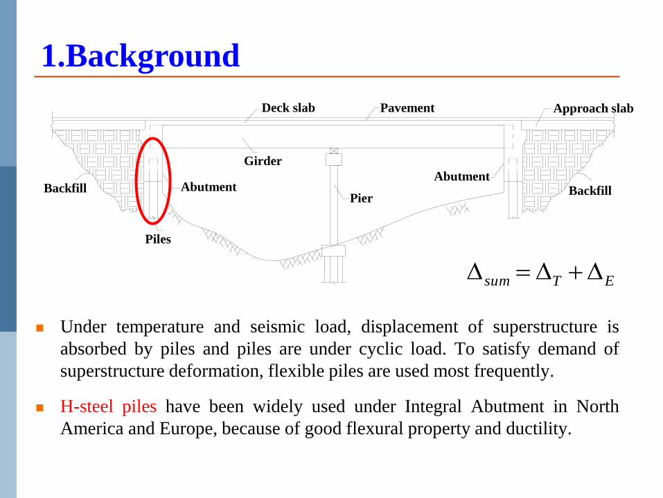
Under temperature and seismic load, displacement of superstructure is
absorbed by piles and piles are under cyclic load. To satisfy demand of
superstructure deformation, flexible piles are used most frequently.
H-steel piles have been widely used under Integral Abutment in North
America and Europe, because of good flexural property and ductility.
1.Background
ETsum
Pier
Deck slab
Abutment
Piles
Girder
Backfill
Pavement Approach slab
AbutmentBackfill
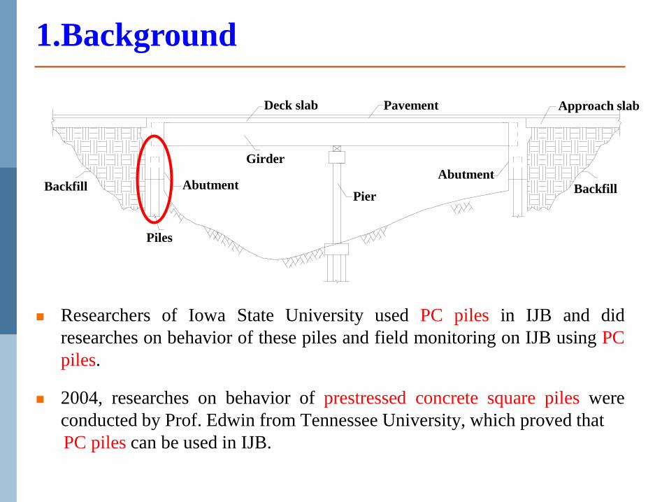
Researchers of Iowa State University used PC piles in IJB and did
researches on behavior of these piles and field monitoring on IJB using PC
piles.
2004, researches on behavior of prestressed concrete square piles were
conducted by Prof. Edwin from Tennessee University, which proved that
PC piles can be used in IJB.
1.Background

Pier
Deck slab
Abutment
Piles
Girder
Backfill
Pavement Approach slab
AbutmentBackfill
“m” method is linear and elastic with a limit 8-10mm in Chinese Code.
“p-y” method is complex or accurate enough for RC piles?
1.Background

t
PHC model piles C80 concrete (has a compressive strength of 82.1 MPa)
With a diameter of 155mm,length of 2.75m
7-wires prestressed steel strand with a diameter of 11.10mm
Labeled as PHC-1 to PHC-4
2. Testing introduction
NumberDiameter
(mm)
Pile
Length
(m)
Wall
Thickness
(mm)
Prestressed
Degree λ
Stirrup
Spacing
(mm)
Deformation
Coefficient
a
Calculate Pile
Length(m)
PHC-1
155 2.75
52.5 0.0 60 1.697 3.988
PHC-2 52.5 0.25 60 1.697 3.988
PHC-3 52.5 0.50 60 1.697 3.988
PHC-4 40.0 0.57 60 1.715 4.031
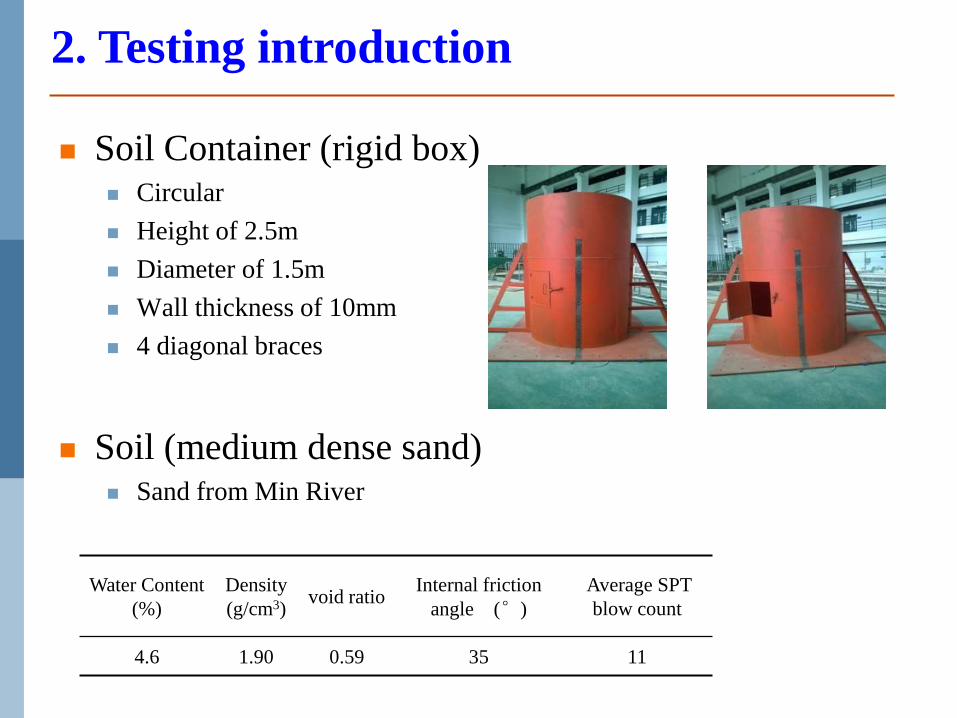
Soil Container (rigid box) Circular
Height of 2.5m
Diameter of 1.5m
Wall thickness of 10mm
4 diagonal braces
Soil (medium dense sand) Sand from Min River
Water Content
(%)
Density
(g/cm3)void ratio
Internal friction
angle (°)
Average SPT
blow count
4.6 1.90 0.59 35 11
2. Testing introduction

Sensor arrangement Strain gages
14 strain gages were installed on piles
with an equal spacing of 350mm,
labeled as S1 to S14.
24
50
10
02
50
35
03
50
35
03
50
35
03
50
S1 S8
S2
S3
S4
S5
S6
S7
S9
S10
S11
S12
S13
S14
Soil surface
2. Testing introduction

Sensor arrangement Earth pressure cells
12 earth pressure cells were
installed on piles with an equal
spacing of 350mm, labeled as T1 to
T12.
10
04
25
35
03
50
35
03
50
35
01
75
T1
T2
T3
T4
T5
T6
T7
T8
T9
T10
T11
T12
Soil surface
2. Testing introduction

Sensor arrangement Displacement meters
8 displacement meters were installed,
labeled as D1 to D8.
D1
D2
D3
D4
D5
D6
D7
D8
10
02
50
35
03
50
35
03
50
35
03
50
40
0Soil surface
2. Testing introduction
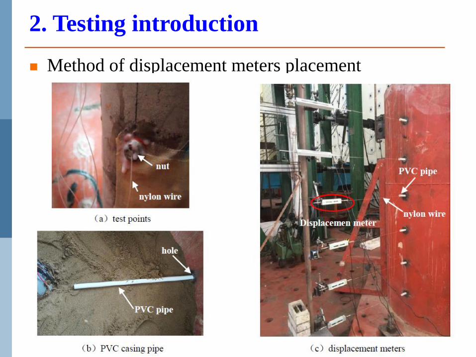
Method of displacement meters placement
2. Testing introduction
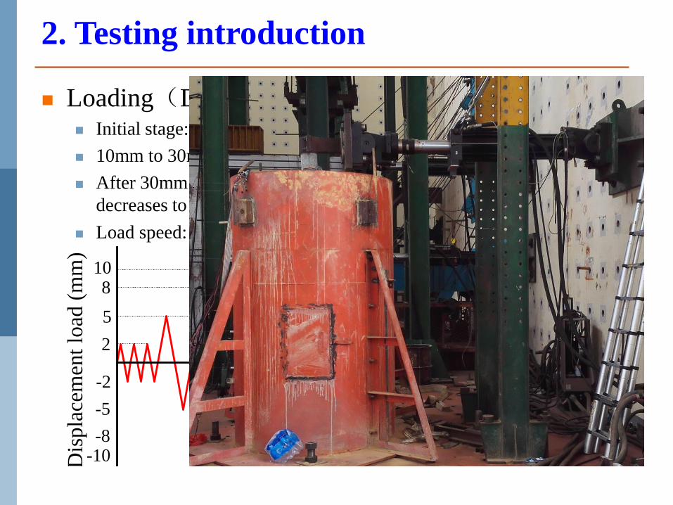
Loading(Displacement loading method) Initial stage: 2 mm, 5mm, 8mm and 10mm.
10mm to 30mm: increase by 5mm.
After 30mm: increase by 10 mm, and the test end until the lateral force
decreases to 85% of peak value.
Load speed: 1.0mm/s. 3 cycles every load grade。
Dis
pla
cem
ent
load
(m
m)
..
-10-8
-5
-2
..
108
5
2
2. Testing introduction

3.1 Failure modes
3. Testing Results
PHC-2 PHC-4
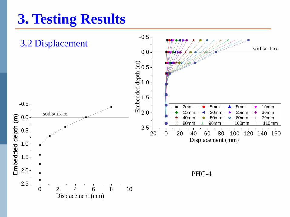
3.2 Displacement
-20 0 20 40 60 80 100 120 140 1602.5
2.0
1.5
1.0
0.5
0.0
-0.5
soil surface
Em
bed
ded
dep
th (
m)
Displacement (mm)
2mm 5mm 8mm 10mm
15mm 20mm 25mm 30mm
40mm 50mm 60mm 70mm
80mm 90mm 100mm 110mm
0 2 4 6 8 102.5
2.0
1.5
1.0
0.5
0.0
-0.5
soil surface
Em
bedded d
epth
(m
)
Displacement (mm)
3. Testing Results
PHC-4

3.3 Hysteretic curve and skeleton curve
-150 -100 -50 0 50 100 150-20
-15
-10
-5
0
5
10
15
20
Displacement mm
Load
kN
-150 -100 -50 0 50 100 150-20
-15
-10
-5
0
5
10
15
20
Load
kN
Displacement mm
-150 -100 -50 0 50 100 150-20
-15
-10
-5
0
5
10
15
20
Load
kN
Displacement mm
-Pu=-12.4kN
-yu=-109.6mm -P
cr=-5.5kN
-ycr=-9.9mm
Pcr=5.4kN
ycr=10.0mm P
u=11.5kN
yu=110.0mm
-150 -100 -50 0 50 100 150-20
-15
-10
-5
0
5
10
15
20
Lo
ad k
N
Displacement mm
-Pu=-16.3kN
-Yu=-119.1mm
-Pcr=-5.1kN
-Ycr=-9.2mm
Pcr=5.3kN
Ycr=9.9mm
Pu=15.9kN
Yu=119.4mm
PHC-2PHC-4
PHC-2PHC-4
3. Testing Results

3.4 Strain distribution and strain history
-400 -300 -200 -100 0 100 200
2.5
2.0
1.5
1.0
0.5
0.0
-0.5
soil surface
Em
bed
de
d d
epth
(m
)
strain ×10-6
2mm
5mm
8mm
10mm
15mm
0 5 10 15 20 25 300
30
60
90
120
150
180
210
theoretic crack strain value
Ten
sile
str
ain
×1
0-6
Displacement load (mm)
0.35m depth
0.70m depth
1.05m depth
1.40m depth
0 10 20 30 40 50 60 70 80 900
-250
-500
-750
-1000
Displacement load (mm)
0.35m depth
0.70m depth
1.05m depth
1.40m depth
Co
mp
ress
ive
stra
in ×
10
-6
-400 -300 -200 -100 0 100 200
2.5
2.0
1.5
1.0
0.5
0.0
-0.5
soil surface
Em
bed
de
d d
epth
(m
)
strain ×10-6
2mm
5mm
8mm
10mm
15mm
0 5 10 15 20 25 300
30
60
90
120
150
180
210
240
Displacement load (mm)
theoretic crack strain value
0.35m depth
0.70m depth
1.05m depth
1.40m depth
Ten
sile
str
ain
×1
0-6
0 10 20 30 40 50 60 70 80 900
-250
-500
-750
-1000
Co
mp
ress
ive
stra
in ×
10
-6Displacement load (mm)
0.35m depth
0.70m depth
1.05m depth
1.40m depth
PHC-2 PHC-2 PHC-2
PHC-4 PHC-4 PHC-4
3. Testing Results

3. Testing Results
0 10 20 30 40 50 60 70 80
0
20
40
60
80
100
120
Ea
rth
Pre
ssu
re (
kPa
)
Displacement Loads (mm)
T1
T2
T3
T4
T5
T6
-10 0 10 20 30 40 50 602.5
2.0
1.5
1.0
0.5
0.0
-0.5
Earth Surface
Em
bed
de
d D
epth
(m
)
Earth Pressure (kPa)
2mm
5mm
8mm
10mm
15mm
-5 0 5 10 15 20 25-5
0
5
10
15
20
25
30
35
Eart
h P
ress
ure
(k
Pa)
Displacement Loads (mm)
T1
T2
T3
T4
T5
T6
-5 0 5 10 15 20 25 302.5
2.0
1.5
1.0
0.5
0.0
-0.5
Em
bed
ded
Dep
th (
m)
Earth Pressure (kPa)
2mm
5mm
8mm
10mm
15mm
3.5 Pile soil pressure
PHC-2
PHC-2
PHC-4
PHC-4

4. Calculation on pile-soil interaction
zCzCdzCP ssu 321 ,)/(min API
)tantan1(
)tan(
tan
cos)tan(
sintan[ a
D
z
aD
zKzAP ssu
])tansin(tantan as KaD
zK
Reese LFP
Broms 3u s pP K Dz
nn
prsu azDKSP )( 0
22 Guo
zyzmP u“m”
4.1 Soil pressure calculate

4. Calculation on pile-soil interaction
0 15 30 45 602.5
2.0
1.5
1.0
0.5
0.0
-0.5
Em
bed
ded
Dep
th (
m)
Earth Pressure (kPa)
API 1993
Reese
Broms
Guo
Test
0 20 40 60 802.5
2.0
1.5
1.0
0.5
0.0
-0.5
Em
bed
ded
Dep
th (
m)
Soil pressure
API 1993
Reese
Broms
Guo
Test
0 25 50 75 1002.5
2.0
1.5
1.0
0.5
0.0
-0.5
Em
bed
ded
Dep
th (
m)
Earth Pressure (kPa)
API 1993
Reese
Broms
Guo
Test
0 25 50 75 100 1252.5
2.0
1.5
1.0
0.5
0.0
-0.5
Em
bed
ded
Dep
th (
m)
Soil pressure
API 1993
Reese
Broms
Guo
Test
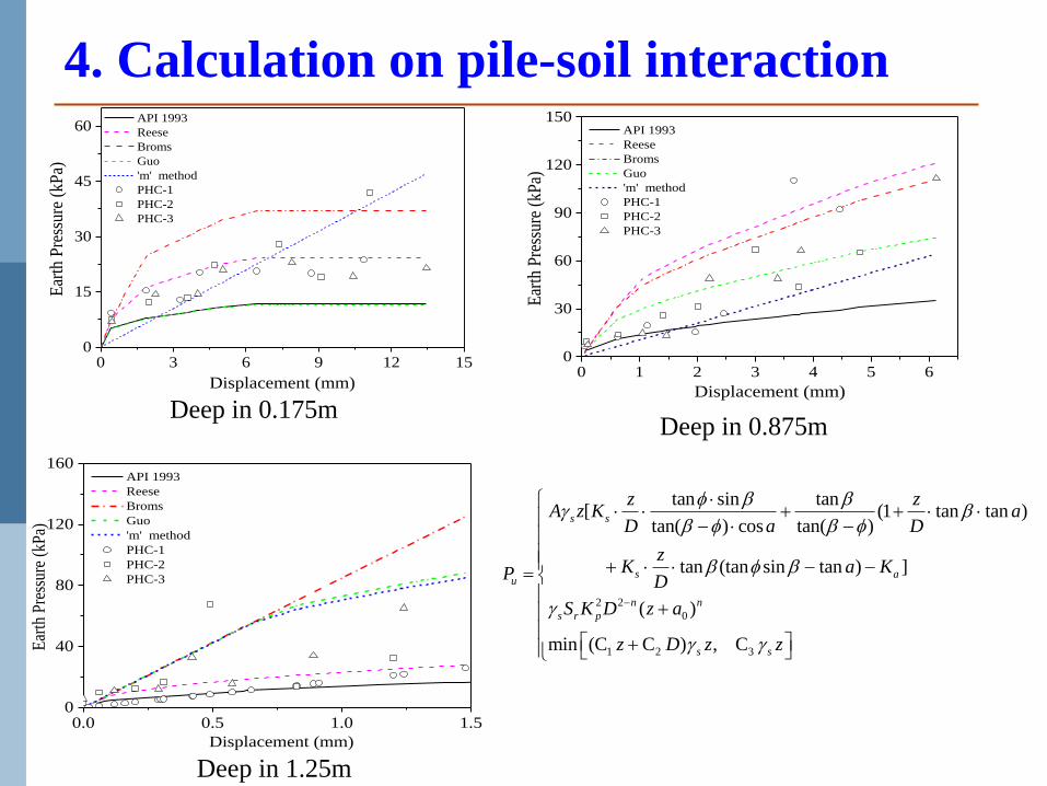
4. Calculation on pile-soil interaction
0 3 6 9 12 150
15
30
45
60
Ear
th P
ress
ure
(kP
a)
Displacement (mm)
API 1993
Reese
Broms
Guo
'm' method
PHC-1
PHC-2
PHC-3
0 1 2 3 4 5 60
30
60
90
120
150
Ear
th P
ress
ure
(kP
a)
Displacement (mm)
API 1993
Reese
Broms
Guo
'm' method
PHC-1
PHC-2
PHC-3
0.0 0.5 1.0 1.50
40
80
120
160
Ear
th P
ress
ure
(kP
a)
Displacement (mm)
API 1993
Reese
Broms
Guo
'm' method
PHC-1
PHC-2
PHC-3
2 2
0
1 2 3
tan sin tan[ (1 tan tan )
tan( ) cos tan( )
tan (tan sin 15 1
5
tan ) ] (
( ) ( 21
min (C C ) , C 3(15
s s
s au
n n
s r p
s s
z zA z K a
D a D
zK a KP D
S K D z a
z D z z
)
)
)
Deep in 0.175m Deep in 0.875m
Deep in 1.25m

4.2 Bending moment
Strain Bending moment of pile
EIM
D
When the pile is elastic
2 2/EI
M EId y d zD
Get displacement by quadratic integral of bending curvature
4. Calculation on pile-soil interaction
-1 0 1 2 3 4 5 6
2.5
2.0
1.5
1.0
0.5
0.0
-0.5
soil surface
Bending moment (kN·m)
Em
be
dd
ed
de
pth
(m
)
2mm
5mm
8mm
10mm
15mm
20mm
25mm
-1 0 1 2 3 4 5 6
2.5
2.0
1.5
1.0
0.5
0.0
-0.5
soil surface
Bending moment (kN·m)
Em
bedded d
epth
(m
) 2mm
5mm
8mm
10mm
15mm
20mm
25mm
PHC-2 PHC-4
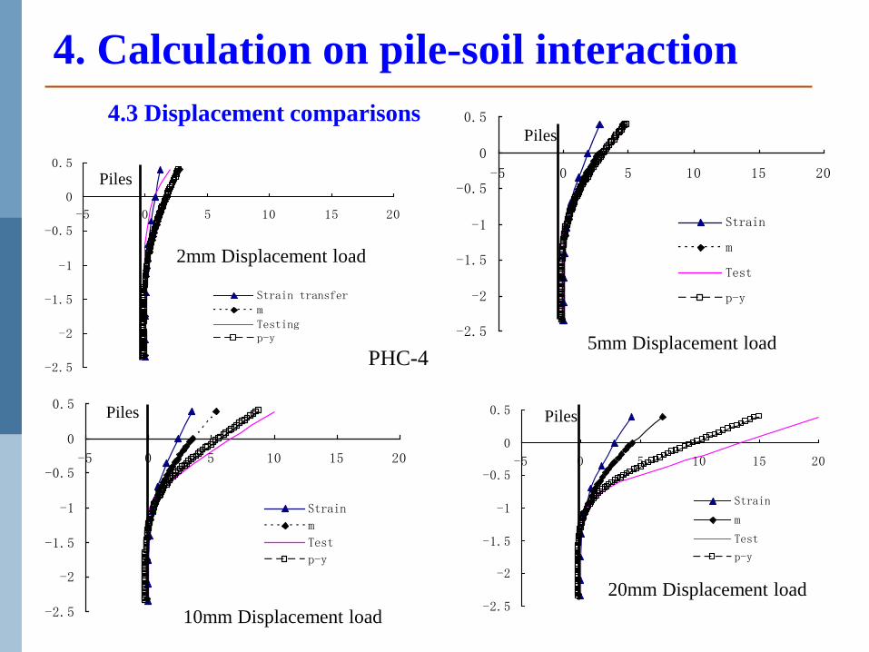
4. Calculation on pile-soil interaction
-2.5
-2
-1.5
-1
-0.5
0
0.5
-5 0 5 10 15 20
Strain transfermTestingp-y -2.5
-2
-1.5
-1
-0.5
0
0.5
-5 0 5 10 15 20
Strain
m
Test
p-y
-2.5
-2
-1.5
-1
-0.5
0
0.5
-5 0 5 10 15 20
Strain
m
Test
p-y
-2.5
-2
-1.5
-1
-0.5
0
0.5
-5 0 5 10 15 20
Strain
m
Test
p-y
Piles
Piles
Piles Piles
PHC-4
2mm Displacement load
5mm Displacement load
10mm Displacement load
20mm Displacement load
4.3 Displacement comparisons

4. Calculation on pile-soil interaction
0 10 20 30 40 502.5
2.0
1.5
1.0
0.5
0.0
-0.5
Earth Surface
Em
bed
ded
Dep
th (
m)
Displacement (mm)
Equation (7)
Test Value
0 10 20 30 40 502.5
2.0
1.5
1.0
0.5
0.0
-0.5
Earth Surface
Em
be
dd
ed
De
pth
(m
)
Displacement (mm)
Equation (7)
Test Value
0 10 20 30 40 502.5
2.0
1.5
1.0
0.5
0.0
-0.5
Earth Surface
Em
bed
de
d D
epth
(m
)
Displacement (mm)
Equation (7)
Test Value
0 10 20 30 40 502.5
2.0
1.5
1.0
0.5
0.0
-0.5
Earth Surface
Em
bedd
ed D
epth
(m
)
Displacement (mm)
Equation (7)
Test Value
(a)10mm Displacement load
(b)15mm Displacement load
(c)20mm Displacement load (d)30mm Displacement load
PHC-4
4.2 New displacement method

4. Calculation on pile-soil interaction
6
1i
iTF
iii bPT Z
(0.9 ) 1.25n
ib y D
F
yu
ym
ykP=Pm(y/ym)1
n
PuPm
Pk
b0/60 3b0/80
n
m
my
ypp /1
i )(
mu
muummu
yy
ypypyppp
)()(i
D
zykp khk
Pi
y
4.3 Simple calculation on pile-soil interaction

4. Calculation on pile-soil interaction
0 30 60 90 120 1500
5
10
15
Fo
rce
(kN
)
Displacement (mm)
simple calculation method
'p-y' curves method
'm' method
Test
0 30 60 90 120 1500
5
10
15
Fo
rce
(kN
)
Displacement (mm)
simple calculation method
'p-y' curves method
'm' method
Test
0 30 60 90 120 1500
5
10
15
For
ce (
kN)
Displacement (mm)
simple calculation method
'p-y' curves method
'm' method
Test
0 30 60 90 120 1500
5
10
15
20
simple calculation method
'p-y' curves method
'm' method
Test
For
ce (
kN)
Displacement (mm)
(a)PHC-1
(b)PHC-2
(c)PHC-3 (d)PHC-4
4.4 Results comparisons

4. Calculation on pile-soil interaction
0 2 4 6 8 103.0
2.5
2.0
1.5
1.0
0.5
0.0
Buri
ed D
epth
(m
)
Displacement (mm)
Test
Calculation
0 5 10 15 20 253
2
1
0
Displacement(mm)
Bur
ied
Dep
th(
m)
Calculation
Test
0 8 16 24 32 403
2
1
0
Bur
ied
Dep
th(
m)
Displacement(mm)
Calculation
Test0 10 20 30 40 50
3
2
1
0
Bur
ied
Dep
th(
m)
Displacement(mm)
Calculation
Test
(a) 10mm Displacement Loading
(b) 25mm Displacement Loading
(c) 40mm Displacement Loading (d) 55mm Displacement Loading
Fan(2014)

4. Calculation on pile-soil interaction
(b) 10mm Displacement Load
-0.5 0.0 0.5 1.0 1.53.0
2.5
2.0
1.5
1.0
0.5
0.0
Bur
ial
Dep
th (
m)
bending moment (kN·m)
Calculation
Test
-0.5 0.0 0.5 1.0 1.53.0
2.5
2.0
1.5
1.0
0.5
0.0
Bur
ial
Dep
th (
m)
bending moment (kN·m)
Calculation
Test
(a) 5mm Displacement load
0 15 30 45 600
5
10
15
For
ce (
kN)
Displacement (mm)
simple calculation method
'p-y' curves method
'm' method
Test
Fan(2014)

Maximal bending moment locates at 5.0D to 6.0D embedded depth,
concrete of pile cracks around this area primarily.
Degree of prestress and reinforcement ratio has a significant influence
on failure mode of PHC piles.
There are four stages for PHC piles: (1) elastic stage when the
displacement of pile head below 8mm~10mm. (2) Concrete of tensile
zone cracked, which means soil-pile system become elastic-plastic. (3)
Reaching 40mm displacement load, concrete of compressive zone are
out of work, stiffness of pile decreases gradually. After that, soil-pile
separation has a significant influence. (4) failure stage: lateral bearing
capacity drops dramatically.
The test indicate that the distribution law of soil pressure is that with
the change of pile depth, the side earth pressure of pile increased first
and then decreased, and reversed in a certain depth.
5. Conclusion
PHC piles performs a good plastic property and deformation ability
considering soil-pile interaction, which is a suitable type used in IJB.
With the increase of displacement loads, the pressure of shallow soil
grows faster and its maximum is close to the limit passive earth
pressure, while that of the deep soil is relatively slow or even increase
reversely.
It can be seen that the transformation method and the 'm' method to
calculate the horizontal deformation of pile are not accurate for
nonlinear elastic and larger deformation. Although the 'p-y' curves
method takes the non-linear effects of soil into account , there still
exists a large error in calculating the large deformation value.
The horizontal displacement calculation method of pile-soil interaction
that obtained by tests can calculate precisely and accurately the pile
displacement.
5. Conclusion

Thanks for your attention!
THE 3RD INTERNATIONAL JOINTLESS BRIDGES
WORKSHOP


![Internal - Luciano Chinellato · AnyOne® Internal è -P_[\YL 3L]LS 7YVZ[OLZPZ EZ Post Milling Abutment Angled Abutment CCM Abutment Temporary Abutment [Titanium] Temporary Abutment](https://static.fdocuments.us/doc/165x107/5c038f7909d3f2156d8cd7fd/internal-luciano-anyone-internal-e-pyl-3lls-7yvzolzpz-ez-post-milling.jpg)