Disk Library for mainframe Physical Planning Guide … distribution cabling — DLm8100 26 Customer...
58
Disk Library for mainframe Version 4.5.0 Physical Planning Guide for DLm8100 and DLm2100 302-003-496 REV 03
Transcript of Disk Library for mainframe Physical Planning Guide … distribution cabling — DLm8100 26 Customer...

Disk Library for mainframeVersion 4.5.0
Physical Planning Guide for DLm8100 and DLm2100302-003-496
REV 03

Copyright © 2017 Dell Inc. or its subsidiaries. All rights reserved.
Published August 2017
Dell believes the information in this publication is accurate as of its publication date. The information is subject to change without notice.
THE INFORMATION IN THIS PUBLICATION IS PROVIDED “AS-IS.“ DELL MAKES NO REPRESENTATIONS OR WARRANTIES OF ANY KIND
WITH RESPECT TO THE INFORMATION IN THIS PUBLICATION, AND SPECIFICALLY DISCLAIMS IMPLIED WARRANTIES OF
MERCHANTABILITY OR FITNESS FOR A PARTICULAR PURPOSE. USE, COPYING, AND DISTRIBUTION OF ANY DELL SOFTWARE DESCRIBED
IN THIS PUBLICATION REQUIRES AN APPLICABLE SOFTWARE LICENSE.
Dell, EMC, and other trademarks are trademarks of Dell Inc. or its subsidiaries. Other trademarks may be the property of their respective owners.
Published in the USA.
EMC CorporationHopkinton, Massachusetts 01748-91031-508-435-1000 In North America 1-866-464-7381www.EMC.com
2 Disk Library for mainframe 4.5.0 Physical Planning Guide for DLm8100 and DLm2100

5
7
Physical Planning Overview 9Planning overview....................................................................................... 10DLm system presite considerations.............................................................10
Physical specifications.................................................................... 11General considerations....................................................................11Transportation and delivery guidelines............................................ 11
Pre-installation considerations.....................................................................11Environmental specifications..........................................................12System host cabling requirements................................................. 12Layout and space recommendations.............................................. 12Remote support............................................................................. 12EMC Secure Remote Support........................................................ 12Establishing SSH trust................................................................... 13Planning for upgrades.................................................................... 13
Configuration and host connectivity 15Network software ports needed to support DLm operations....................... 16Network software ports needed to support DLm Disaster Recovery Testing....................................................................................................................17Installation information................................................................................17
DLm8100 with VNX and Data Domain Physical Planning 19DLm8100 with VNX and DD Physical Planning Overview............................ 20
VTEC cabinet................................................................................ 20VNX cabinet.................................................................................. 20VNX storage cabinet...................................................................... 21Data Domain cabinet...................................................................... 21DAE................................................................................................21Modems.........................................................................................22
DLm8100 VNX and DD Configuration and Host Connectivity......................22Network software ports needed to support DLm Replicationoperations......................................................................................22Network software ports needed to support DLm debuggingoperations......................................................................................23
DLm8100 Physical Data Requirements....................................................... 24DLm power requirements........................................................................... 25
Power and cooling data................................................................. 26External network and phone line requirements........................................... 27
DLm8100 with VNX and Data Domain............................................ 27
DLm8100 with VMAX Physical Planning 29DLm8100 VMAX Physical Planning Overview............................................. 30
VTEC cabinet................................................................................ 30
Figures
Tables
Chapter 1
Chapter 2
Chapter 3
Chapter 4
CONTENTS
Disk Library for mainframe 4.5.0 Physical Planning Guide for DLm8100 and DLm2100 3

VNX VG8 Cabinet.......................................................................... 30VMAX system cabinet and storage cabinets..................................30Modems......................................................................................... 31
DLm8100 VMAX Physical and Environmental Specifications....................... 31Physical data..................................................................................31External network and phone line requirements in DLm8100........... 32DLm power requirements...............................................................33
DLm2100 with Data Domain or CloudArray Physical Planning 35Overview of DLm2100................................................................................ 36
DLm2100 with Data Domain...........................................................36DLm2100 with CloudArray............................................................. 36
DLm2100 Physical specifications................................................................36Physical data................................................................................. 36External network and phone line requirements.............................. 37Shipping dimensions...................................................................... 37System placement......................................................................... 37
Power requirements for DLm2100.............................................................. 37Power and cooling data..................................................................37
Environmental specifications and regulatory compliance 39Environmental specifications......................................................................40
Air flow.......................................................................................... 40Environment acclimation............................................................... 40
Regulatory compliance................................................................................41DLm touch current compliance...................................................................42Choosing a UPS..........................................................................................42
DLm8100 System Service Area and Removal 45Dimensions and service area.......................................................................46Shipping dimensions and clearance requirements.......................................46System placement......................................................................................48
DLm8100 configuration floor cutouts.............................................48Anti-tip and anti-move brackets.................................................... 49
Package Removal....................................................................................... 50Inspect the system shipment......................................................... 51Unpacking procedure..................................................................... 51
Inspecting and Unpacking the DLm2100 DD System 55Inspect the system shipment......................................................................56Unpacking procedure................................................................................. 56DLm2100 configuration floor cutout........................................................... 56
Chapter 5
Chapter 6
Appendix A
Appendix B
CONTENTS
4 Disk Library for mainframe 4.5.0 Physical Planning Guide for DLm8100 and DLm2100

Power distribution cabling — DLm8100......................................................................26Customer (external) connections for DLm8100.......................................................... 27DLm8100 dual VG8 cabinet.........................................................................................33Power distribution cabling — DLm8100......................................................................34DLm8100 cabinet dimensions and access area............................................................46Shipping dimensions................................................................................................... 47Unloading the pallet....................................................................................................48DLm8100 configuration floor cutout........................................................................... 49Rack measurements for anti-tip brackets...................................................................50Rack measurements for anti-move brackets.............................................................. 50Cutting the tape and straps........................................................................................52Removing the packing material of the cabinet............................................................ 52DLm2100 configuration floor cutout........................................................................... 57
12345678910111213
FIGURES
Disk Library for mainframe 4.5.0 Physical Planning Guide for DLm8100 and DLm2100 5

FIGURES
6 Disk Library for mainframe 4.5.0 Physical Planning Guide for DLm8100 and DLm2100

Pre-installation responsibility summary....................................................................... 10Required Network Ports for DLm Operations ............................................................. 16Required Network Port for Disaster Recovery Testing................................................17External dependencies................................................................................................ 17Required Network Port for DLm8100 DD Replication................................................. 22Required Network Ports for DLm8100 VNX Replication............................................. 22Required Network Ports for DLm8100 with VNX Extreme Debugging........................ 23DLm physical specification for a single cabinet...........................................................24North American, single-phase, electrical specifications.............................................. 25DLm8100 power consumption and heat dissipation.....................................................26DLm8100 customer network cable requirements........................................................ 27DLm8100 phone line requirements..............................................................................28DLm8100 replication cable requirements.................................................................... 28Physical specification of the VTEC and VG8 cabinets................................................. 31DLm8100 external network and phone line requirements............................................32North American, single-phase, electrical specifications ............................................. 33DLm8100 power consumption and heat dissipation.....................................................34Power Requirements.................................................................................................. 37DLm environmental data.............................................................................................40Environmental requirements for shipping and storage................................................ 40Environmental acclimation..........................................................................................40
123456789101112131415161718192021
TABLES
Disk Library for mainframe 4.5.0 Physical Planning Guide for DLm8100 and DLm2100 7

TABLES
8 Disk Library for mainframe 4.5.0 Physical Planning Guide for DLm8100 and DLm2100

CHAPTER 1
Physical Planning Overview
This chapter provides an overview of the planning requirements for EMC® DiskLibrary for mainframe (DLm) installation.
l Planning overview...............................................................................................10l DLm system presite considerations.................................................................... 10l Pre-installation considerations............................................................................ 11
Physical Planning Overview 9

Planning overviewThis section provides an overview of the planning requirements for EMC® Disk Libraryfor mainframe (DLm) installation. It reviews EMC responsibilities and outlines yourresponsibilities as a DLm user for the following DLm systems:
l DLm8100 with VNX, Data Domain, and/or CloudArray
l DLm8100 with VMAX and/or CloudArray
Note
This document contains information about the VTEC cabinet and the VNX VG8cabinet of a DLm8100. Refer to the EMC VMAX 20K/VMAX Series Physical PlanningGuide [P/N 300-008-601] for information about the VMAX.
l DLm2100 with Data Domain and/or Cloud Array (CA)
Note
Inform EMC of any labor union-based restrictions or security clearance requirementsprior to delivery.
The DLm systems must be installed in a properly equipped computer room withcontrolled temperature and humidity, proper airflow and ventilation, proper power andgrounding, system cable routing facilities, fire equipment, and so on. A raised floor isrecommended, although it is not required. One or more planning sessions with yourSystems Engineer and Customer Support Representative will be necessary to close allthe details related to installation. The table below lists the responsibility summary atthe first planning session.
Table 1 Pre-installation responsibility summary
EMC You
Provide all details necessary for site planningand preparation.
Provide an environment that supports safeinstallation of the DLm system and promotesits reliable long-term operation.
Complete and process the InstallationPlanning Task Sheet and Presite Survey.
Provide appropriate modem phone line,power, cooling and ventilation, humiditycontrol, floor load capability, and serviceclearances as required.
Arrange for shipment and delivery through anappropriate method.
Participate in planning sessions as required toensure a smooth and uncomplicatedinstallation.
Install a properly working system.
DLm system presite considerationsWhen planning the installation site for your DLm system, meet with your EMCrepresentative to complete the presite plan.
Physical Planning Overview
10 Disk Library for mainframe 4.5.0 Physical Planning Guide for DLm8100 and DLm2100

Physical specificationsThe physical and environmental specifications section provides overall systemdimensions for the following DLm systems:
l DLm8100 VNX, DD, and/or CA
l DLm8100 VMAX and/or CA
l DLm2100 DD and/or CA
General considerationsBefore installing the DLm system at your site, consider these factors:
l Weight capacities of the service elevator if delivery is to another floor
l Availability of an equipment ramp if the receiving floor is not on the same level asthe computer room floor.
Note
All portions of the cabinet should clear ramp and threshold slopes up to 1:10 (riseto run ratio), per Code of Federal Regulations – ADA Standards for AccessibleDesign, 28 CFR Part 36.
l Weight capacities of the loading dock
l Weight capacities of the tailgate
Other requirements are:
l Appropriate floor covering for protection
l Direct dial-up phone line (for remote support) within 6 ft (two meters) of the unit
l Hardware power requirements
l Power requirements for the DLm cabinets
Transportation and delivery guidelinesMode of transport guidelines:
l For all DLm systems delivered within the United States or Canada, EMCrecommends an air-ride truck.
l All DLm systems are wrapped in custom-designed shipping material. The DLmsystem may also be crated and palletized.
l For all DLm systems delivered internationally, EMC recommends shipment by airfreight. Unless otherwise instructed, the EMC Traffic Department arranges fordelivery directly to the computer room.
To ensure successful delivery of DLm systems, EMC has formed partnerships withspecially selected moving companies. These companies have moving professionalstrained to properly handle large, sensitive systems. These companies provide theappropriate personnel, floor layouts, and any ancillary moving equipment required tofacilitate delivery.
Pre-installation considerationsInstall the DLm in a properly equipped and well-ventilated computer room.
Physical Planning Overview
Physical specifications 11

Environmental specificationsDLm requires the environmental specifications outlined in each chapter for thespecific DLm model. Ensure that the site meets or exceeds the specifications listed forboth raised and non-raised floor environments.
System host cabling requirementsThe Presite Survey, completed with the EMC Systems Engineer, reports the Fibreconnection (FICON) cable length required for each host connection to the DLm. Froma physical planning perspective, review the routing paths from the hosts to the DLmsystem. Resolve any physical access issues before the installation day.
Layout and space recommendationsLayout and space considerations are described in the chapter for the spcific DLmmodel.
CAUTION
When moving the DLm cabinets down an incline, the rear of the cabinet must gofirst and when moving up an incline, the rear of the cabinet must go last.
Remote supportRemote support is an important and integral part of the EMC customer service andsupport strategy. Communication between the EMC Customer Support Center andthe DLm occurs either through IP connections to the local area network, or throughthe external serial modem connected to the DLm, which requires that you provide onededicated phone line for the modem. You can move phone lines between modemsconnected to the Management VTEs and Control Stations as needed.
For the following models:
l DLm8100 supports one modem in each of its Management VTEs and ControlStations. Modems section provides more information about the modems DLm8100supports.
l DLm2100 supports: one modem in each of its Management VTEs and ControlStations. External network and phone line requirements provides more informationabout the modems DLm2100 supports.
Note
If you decide on a modem connection instead of an IP/LAN connection, then EMCrecommends that you provide one dedicated phone line for the DLm system toenable ConnectEMC call-homes.
EMC Secure Remote SupportDLm supports EMC Secure Remote Support (ESRS) Gateway that provides a secure,IP-based, distributed remote service support solution giving you command, control,and visibility of remote support access.
Contact EMC Customer Support to configure ESRS. This is an optional feature.
Physical Planning Overview
12 Disk Library for mainframe 4.5.0 Physical Planning Guide for DLm8100 and DLm2100

Establishing SSH trustDLm features such as DLm health monitoring, DDRL, command processors,configuration, and setup tools must run commands and operations on the backendstorage systems (VNX, DD, and so on) remotely. For this to work, SSH trust must beestablished between DLm VTEs and the backend storage systems. SSH trust ensuresthat applications on the DLm can run commands on the storage system without apassword. SSH trust is established when DLm is installed, or when new storagesystems or VTEs are added to the DLm.
Planning for upgradesWhen planning for upgrades, consider space, power, and environmental concerns.
Physical Planning Overview
Establishing SSH trust 13
Physical Planning Overview
14 Disk Library for mainframe 4.5.0 Physical Planning Guide for DLm8100 and DLm2100

CHAPTER 2
Configuration and host connectivity
This section describes the configuration and host connectivity requirements commonto all DLm modules.
l Network software ports needed to support DLm operations.............................. 16l Network software ports needed to support DLm Disaster Recovery Testing...... 17l Installation information....................................................................................... 17
Configuration and host connectivity 15

Network software ports needed to support DLm operationsDLm software makes use of many protocols and standard network ports to supportvarious monitoring and configuration services. If your network configuration requiresthat firewalls exist between DLm systems, ensure that the networking environmentinto which you introduce DLm systems provides access to these networking ports andprotocols. Common uses for these network ports are for access:
l Between the DLm and the ESRS gateways
l To user interfaces such as:
n DLm Console
n Data Domain system manager
n CloudArray
The following table provides a list of required network software ports and protocols,along with indications as to what services make use of them.
Table 2 Required Network Ports for DLm Operations
PortNumber
Port Type Protocol(s)
Traffic User Direction ofTraffic
Notes
20 TCP FTP Data Outbound To/FromESRS
21 TCP FTP Command/Control
Inbound/Outbound
To/FromESRS
22 TCP SSH/SCP Secure Shell/Secure Copy
Inbound/Outbound
To/FromESRS
25 TCP SMTP E-mail Outbound Data DomainandConnectEMC
53 UDP DNS BIND/DomainName Service
Outbound N/A
80 TCP HTTP Web Server Inbound/Outbound
Redirects to443 (secureHTTP)
123 UDP NTP Network TimeService
Outbound N/A
161 UDP SNMP Receiver ofSNMP Traps
Outbound N/A
162 UDP SNMPTRAP Sender ofSNMP Traps
Outbound N/A
389 TCP/UDP LDAP LightweightDirectoryAccess
Inbound/Outbound
Userinterfaces
443 TCP HTTPS Webinterfaces
Inbound/Outbound
Userinterfaces
Configuration and host connectivity
16 Disk Library for mainframe 4.5.0 Physical Planning Guide for DLm8100 and DLm2100

Table 2 Required Network Ports for DLm Operations (continued)
PortNumber
Port Type Protocol(s)
Traffic User Direction ofTraffic
Notes
636 TCP/UDP LDAP Secure LDAP Inbound/Outbound
N/A
Network software ports needed to support DLm DisasterRecovery Testing
To perform DLm Disaster Recovery testing on a mainframe and to allow the mainframeto write data to the back-end storage, you must configure your firewalls to allowtraffic on particular network ports that are different for each back-end storagesystem type.
The following table lists the special port for Disaster Recovery testing for the variousDLm models.
Table 3 Required Network Port for Disaster Recovery Testing
DLmModel
Port Number Port Type TrafficUser
Directionof Traffic
Notes
DLm8100with VNXand DD
9876 TCP DLm SPDefault
Outbound DR Testingto maintain
DLm2100 2051 TCP Replication Inbound/Outbound
Proprietaryprotocol
DLm8100with VMAX
9095 TCP DLMDRC/DLm disasterrecovery
Outbound DR tomaintain
Installation informationDiscuss and obtain the following site profile information from the EMC SalesRepresentative. The following table lists the external dependencies that need to beconsidered for configuring DLm systems.
Table 4 External dependencies
Requirements Specifications
Mainframe software l Operating system and version number
l JES2 or JES3
Channel information l Channel type
l Number of channels
l Type of channels: FICON
Configuration and host connectivity
Network software ports needed to support DLm Disaster Recovery Testing 17

Table 4 External dependencies (continued)
Requirements Specifications
Configuration information l LPARs which will use DLm
l Physical Control Unit Address (CUADD)
l Physical Device Addresses (UNITADD)
l Device type
l Device name— logical device name forVTE display
l Tape volume prefix
Tape management system information l Tape management system
l Version
l Scratch reports used
Tape volume information l Volume serial number range for VTEtapesa
l Quantity of tape volumes
Purpose of DLm l Number of physical drives that will bereplaced by virtual tapes
l Mainframe applications that will accessthe virtual tapes
l Backup software that will be used on theVTE
a. DLm can support many such VOLSER ranges.
Configuration and host connectivity
18 Disk Library for mainframe 4.5.0 Physical Planning Guide for DLm8100 and DLm2100

CHAPTER 3
DLm8100 with VNX and Data Domain PhysicalPlanning
This chapter covers the tasks to be completed when planning an installation of theDLm8100 with VNX and Data Domain (DD) system at the customer site.
l DLm8100 with VNX and DD Physical Planning Overview....................................20l DLm8100 VNX and DD Configuration and Host Connectivity............................. 22l DLm8100 Physical Data Requirements............................................................... 24l DLm power requirements................................................................................... 25l External network and phone line requirements...................................................27
DLm8100 with VNX and Data Domain Physical Planning 19

DLm8100 with VNX and DD Physical Planning OverviewA DLm8100 configuration is composed of:
l A VTEC cabinet including an optional CloudArray server
l Up to two VNX cabinets
l Up to two Data Domain (DD) cabinets (DD9500, DD7200, DD990)
l Up to 10 VNX storage cabinets
DLm supports DAEs with 2, 3, or 4 TB drives.
CAUTION
The DLm8100 VTEC, VNX, Data Domain, and VNX storage cabinet equipmentenclosures and power systems are designed to support DLm8100 systemequipment only. EMC does not support any other components in these cabinets,and recommends that you do not install any additional equipment in the DLm8100cabinets.
VTEC cabinetThe DLm8100 VTEC cabinet contains:
l One to eight VTEs including one or two management VTEs
l Two 10 GbE switches
l Two 1 GbE switches
The DLm VTEC cabinet has two power zones with independent power cables—one foreach side, capable of powering the fully configured cabinet.
Note
Channel extenders are not supported.
VNX cabinetThe DLm8100 VNX cabinet contains:
l One storage system (VNX7500 or VNX7600) and integrated storage arrays with:
n Two to eight storage controllers (Data Movers)
n Two Control Stations
n Two storage processors—SPA and SPB
n Dual standby power supplies
n Up to nine DAEs
l One storage system (VNX5400) and integrated storage arrays with:
n Two to four storage controllers (Data Movers)
n Two Control Stations
n Two storage processors—SPA and SPB
n Dual standby power supplies
n Up to ten DAEs
DLm8100 with VNX and Data Domain Physical Planning
20 Disk Library for mainframe 4.5.0 Physical Planning Guide for DLm8100 and DLm2100
Note
If you need two VNX back-end systems, you must choose one of the followingconfigurations:
l two VNX5400 systems
l two VNX7500 systems
l two VNX7600 systems
The DLm8100 VNX cabinet has four power zones with independent power cables—two for each side, capable of powering a fully configured cabinet.
VNX storage cabinetThe DLm8100 VNX storage cabinet is configured with up to 13 storage DAEs.
The storage cabinet has two power zones with independent power cables—one foreach side, capable of powering a fully configured cabinet.
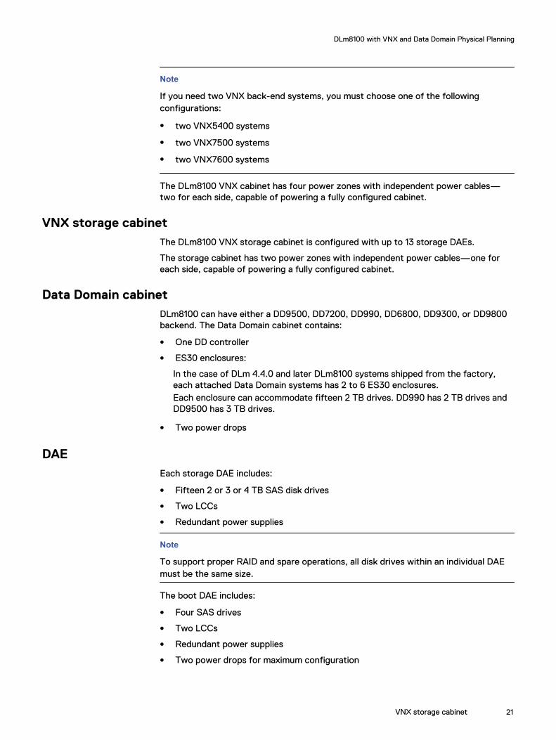
Data Domain cabinetDLm8100 can have either a DD9500, DD7200, DD990, DD6800, DD9300, or DD9800backend. The Data Domain cabinet contains:
l One DD controller
l ES30 enclosures:
In the case of DLm 4.4.0 and later DLm8100 systems shipped from the factory,each attached Data Domain systems has 2 to 6 ES30 enclosures.Each enclosure can accommodate fifteen 2 TB drives. DD990 has 2 TB drives andDD9500 has 3 TB drives.
l Two power drops
DAEEach storage DAE includes:
l Fifteen 2 or 3 or 4 TB SAS disk drives
l Two LCCs
l Redundant power supplies
Note
To support proper RAID and spare operations, all disk drives within an individual DAEmust be the same size.
The boot DAE includes:
l Four SAS drives
l Two LCCs
l Redundant power supplies
l Two power drops for maximum configuration
DLm8100 with VNX and Data Domain Physical Planning
VNX storage cabinet 21

ModemsDLm8100 is shipped with a minimum of two modems. Each Management VTE supportsa modem.
In addition, DLm8100 systems with VNX back-end systems can support two or fourmore modems depending on the number of VNX7500/VNX7600 storage subsystemsattached. Each VNX storage subsystem supports two Control Stations and eachControl Station supports a modem; thus, a DLm8100 system with two VNX7500/VNX7600 storage subsystems supports six modems.
Data Domain systems do not need a modem and is therefore not shipped with one.
DLm8100 VNX and DD Configuration and Host ConnectivityThis section covers the configuration and host connectivity details of the DLm8100with VNX and DD system.
Network software ports needed to support DLm Replication operationsTo support DLm replication operations between backend storage systems, you mustconfigure your firewalls to allow traffic on particular network ports that are differentfor each backend storage system type.
The following table lists the special port for DLm8100 with Data Domain Replication:
Table 5 Required Network Port for DLm8100 DD Replication
Port Number Port Type Traffic User Direction ofTraffic
Notes
2051 TCP Data DomainReplication
Inbound/Outbound
ProprietaryProtocol
The following table lists the special ports for DLm8100 with VNX Replication:
Table 6 Required Network Ports for DLm8100 VNX Replication
Port Number Port Type Traffic User Direction ofTraffic
Notes
5081 TCP VNXReplicatorV2
Inbound/Outbound
Control Traffic(DIC)
5083 TCP VNXReplicatorV2
Inbound/Outbound
Control Traffic(DIC)
5084 TCP VNXReplicatorV2
Inbound/Outbound
Control Traffic(DIC)
5085 TCP VNXReplicatorV2
Inbound/Outbound
Control Traffic(DIC)
8887 TCP VNXReplicatorV2
Inbound/Outbound
Data Transfer
8888 TCP VNXReplicatorV2
Inbound/Outbound
Re-sync
DLm8100 with VNX and Data Domain Physical Planning
22 Disk Library for mainframe 4.5.0 Physical Planning Guide for DLm8100 and DLm2100

Network software ports needed to support DLm debugging operationsUses for these network ports are for access:
l Between the DLm and the ESRS gateways
l To user interfaces such as:
n Unisphere
n USM
Note
If you need to resolve errors, before continuing, you must contact EMC Support forassistance to determine which port to open.
The following table provides a list of required ports along with indications for extremedebugging.
Table 7 Required Network Ports for DLm8100 with VNX Extreme Debugging
Port Number Port Type Traffic User Direction ofTraffic
Notes
2162 TCP NaviSecureCLI(USM)
Inbound/Outbound
ESRS Access
2163 TCP NaviSecureCLI(USM)
Inbound/Outbound
ESRS Access
9219 TCP RemotelyAnywhere
Inbound/Outbound
Navi-SPA/SPB,only neededduring diagnosticoperations
6391 Proprietary RemoteDiagnostic Agent
Inbound/Outbound
Navi-SPA/SPB(ESRS), onlyneeded duringdiagnosticoperations
6392 Proprietary RemoteDiagnostic Agent
Inbound/Outbound
Navi-SPA/SPB(ESRS), onlyneeded duringdiagnosticoperations
8000 TCP VNX Replicator/Unisphere
Inbound/Outbound
Management(ESRS), onlyneeded duringdiagnosticoperations
13456 Proprietary Remote KTrace/KTCONS
Inbound/Outbound
Navi-SPA/SPB,only neededduring diagnosticoperations
13457 Proprietary Remote/ KTrace Inbound/Outbound
Navi-SPA/SPB,only needed
DLm8100 with VNX and Data Domain Physical Planning
Network software ports needed to support DLm debugging operations 23

Table 7 Required Network Ports for DLm8100 with VNX Extreme Debugging (continued)
Port Number Port Type Traffic User Direction ofTraffic
Notes
during diagnosticoperations
60020 Proprietary RemoteDiagnostic Agent
Inbound/Outbound
Navi-SPA/SPB,only neededduring diagnosticoperations
DLm8100 Physical Data RequirementsDLm8100 has a maximum configuration of one VTEC cabinet, two VNX cabinets, 10VNX storage cabinets for VNX7600 and 2 VNX storage cabinets for VNX5400, andtwo DD990, DD7200, or DD9500 cabinets.When fully configured, the weight of each cabinet is:
l VTEC cabinet— 1,060 lb (480.81kg)
l VNX7500/VNX7600 cabinet— 1,414 lb (641.38 kg)
l VNX5400 cabinet— 1,274lb (577.87kg)
l VNX storage cabinet— 1,320 lb (598.74 kg)
l Data Domain cabinet— 1,366 lb (619.61 kg)
l DD storage cabinet — 1225lb (556.82 kg)
Despite the differences in weight, the physical dimensions of all the cabinets are thesame.
Note
All weight values are calculated for a fully loaded configuration. Contact your EMCSales Representative for specific supported configurations.
The following table lists the physical specifications for DLm cabinets.
Table 8 DLm physical specification for a single cabinet
Description Measurements
Height 76.66 in (194.7 cm)a
Width 24.02 in (61.0 cm)
Depth 41.88 in (106.4 cm)
Clearance for service and airflow
Front 42 in (106.7 cm)
Rear 42 in (106.7 cm)
Top 18 in (45.7 cm)
a. With trim kit (optional) attached.
DLm8100 with VNX and Data Domain Physical Planning
24 Disk Library for mainframe 4.5.0 Physical Planning Guide for DLm8100 and DLm2100
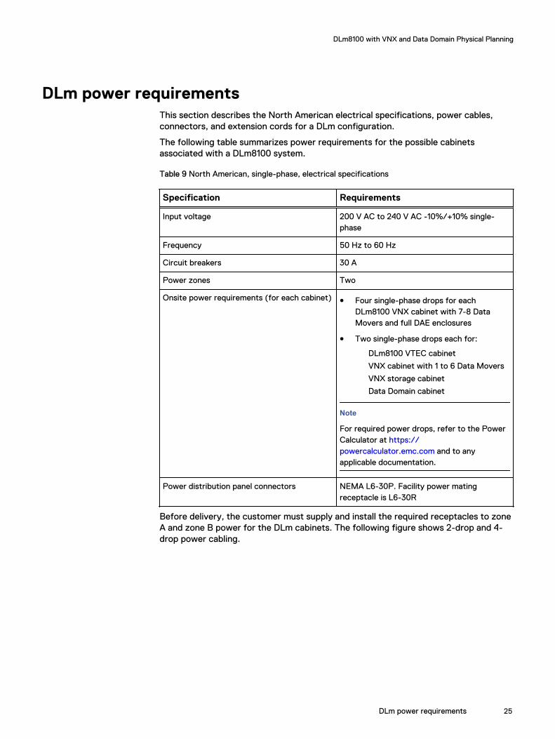
DLm power requirementsThis section describes the North American electrical specifications, power cables,connectors, and extension cords for a DLm configuration.
The following table summarizes power requirements for the possible cabinetsassociated with a DLm8100 system.
Table 9 North American, single-phase, electrical specifications
Specification Requirements
Input voltage 200 V AC to 240 V AC -10%/+10% single-phase
Frequency 50 Hz to 60 Hz
Circuit breakers 30 A
Power zones Two
Onsite power requirements (for each cabinet) l Four single-phase drops for eachDLm8100 VNX cabinet with 7-8 DataMovers and full DAE enclosures
l Two single-phase drops each for:
DLm8100 VTEC cabinet
VNX cabinet with 1 to 6 Data Movers
VNX storage cabinet
Data Domain cabinet
Note
For required power drops, refer to the PowerCalculator at https://powercalculator.emc.com and to anyapplicable documentation.
Power distribution panel connectors NEMA L6-30P. Facility power matingreceptacle is L6-30R
Before delivery, the customer must supply and install the required receptacles to zoneA and zone B power for the DLm cabinets. The following figure shows 2-drop and 4-drop power cabling.
DLm8100 with VNX and Data Domain Physical Planning
DLm power requirements 25

Figure 1 Power distribution cabling — DLm8100
Power and cooling dataThe following table provides details of power consumption and heat dissipation forDLm8100 systems.
Table 10 DLm8100 power consumption and heat dissipation
System configurationdescriptiona
Total power consumption(kVA)
Heat dissipation(Btu/Hr)
VTEC cabinet 3.70 12,300
VNX7500/7600 cabinet 5.15 15,800
VNX5400 cabinet 4.62 14,400
VNX storage cabinet 3.47 10,800
DD990 cabinet 4.76 15,000
DD7200 4.16 12,100
DD storage cabinet 3.36 9600
a. All cabinet values are calculated for a fully loaded configuration. Contact your EMC SalesRepresentative for specific supported configurations.
DLm8100 with VNX and Data Domain Physical Planning
26 Disk Library for mainframe 4.5.0 Physical Planning Guide for DLm8100 and DLm2100

External network and phone line requirementsThe following diagram shows the customer (external) connections for DLm8100 withVNX and Data Domain.
DLm8100 with VNX and Data DomainFigure 2 Customer (external) connections for DLm8100
DLm8100 has at least one management VTE (the first VTE). If a second VTE isconfigured it will be the second management VTE. Each Management VTE has two 1GbE ports (for redundancy) which should be connected to your organization network.It is recommended that one port from each Management VTE is connected to onenetwork switch and the other two ports are connected to another network switch.This ensures that failure of one switch does not affect Management VTE connectivity.
The cables to connect these ports to your network are not supplied with DLm.Therefore, you should provide four network cables to connect the Management VTEto your network.
The following table lists the external customer network requirements for DLm8100.
Table 11 DLm8100 customer network cable requirements
DLm8100 1 GbE cables (Copper)
VTE1 (Management) 2
VTE2 (Management) 2
Modem connectionsDLm8100 provides modems as an optional mechanism for calling home and remoteaccess. (The preferred mechanism is to use ConnectEMC/ESRS.) DLm8100 has onemodem for the first VTE. A second modem is provided for the second VTE ifconfigured. You will need to provide phone lines for these modems. Each VNX also has
DLm8100 with VNX and Data Domain Physical Planning
External network and phone line requirements 27
two modems. If DLm8100 has one VNX, you might need to provide two additionalphone lines; if it has two VNX systems, you might need to provide four additionalphone lines.
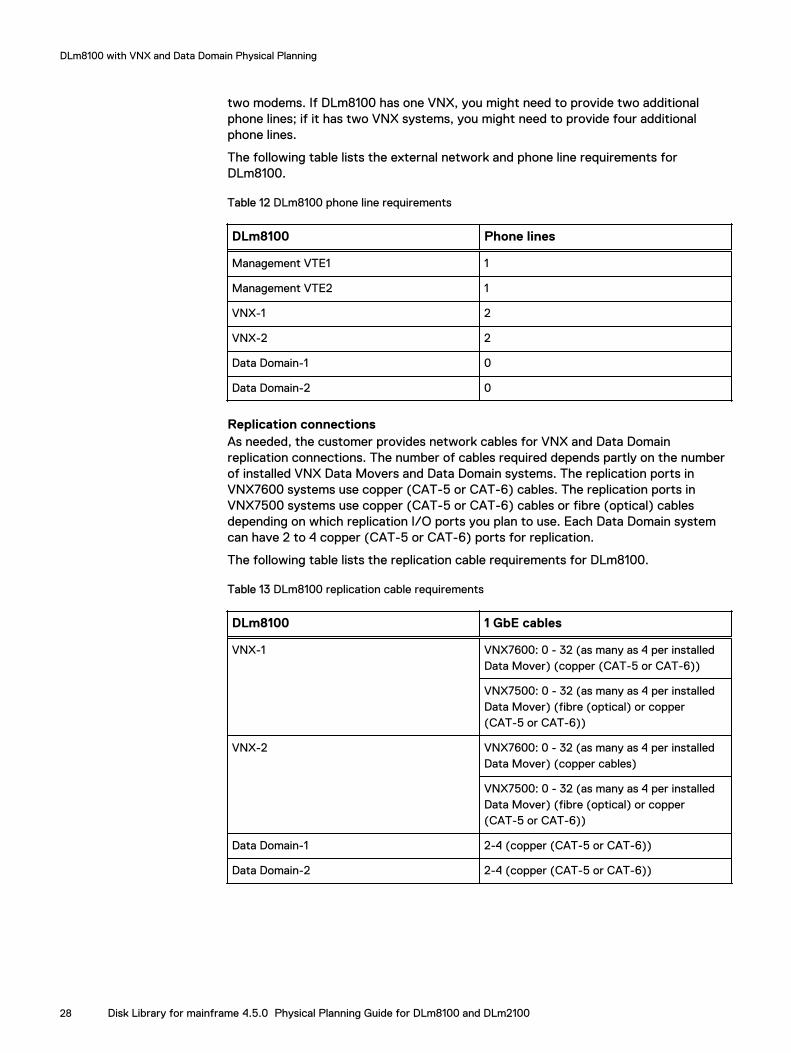
The following table lists the external network and phone line requirements forDLm8100.
Table 12 DLm8100 phone line requirements
DLm8100 Phone lines
Management VTE1 1
Management VTE2 1
VNX-1 2
VNX-2 2
Data Domain-1 0
Data Domain-2 0
Replication connectionsAs needed, the customer provides network cables for VNX and Data Domainreplication connections. The number of cables required depends partly on the numberof installed VNX Data Movers and Data Domain systems. The replication ports inVNX7600 systems use copper (CAT-5 or CAT-6) cables. The replication ports inVNX7500 systems use copper (CAT-5 or CAT-6) cables or fibre (optical) cablesdepending on which replication I/O ports you plan to use. Each Data Domain systemcan have 2 to 4 copper (CAT-5 or CAT-6) ports for replication.
The following table lists the replication cable requirements for DLm8100.
Table 13 DLm8100 replication cable requirements
DLm8100 1 GbE cables
VNX-1 VNX7600: 0 - 32 (as many as 4 per installedData Mover) (copper (CAT-5 or CAT-6))
VNX7500: 0 - 32 (as many as 4 per installedData Mover) (fibre (optical) or copper(CAT-5 or CAT-6))
VNX-2 VNX7600: 0 - 32 (as many as 4 per installedData Mover) (copper cables)
VNX7500: 0 - 32 (as many as 4 per installedData Mover) (fibre (optical) or copper(CAT-5 or CAT-6))
Data Domain-1 2-4 (copper (CAT-5 or CAT-6))
Data Domain-2 2-4 (copper (CAT-5 or CAT-6))
DLm8100 with VNX and Data Domain Physical Planning
28 Disk Library for mainframe 4.5.0 Physical Planning Guide for DLm8100 and DLm2100
CHAPTER 4
DLm8100 with VMAX Physical Planning
This chapter covers the tasks to be completed when planning an installation of theDLm8100 with VMAX system at the customer site.
l DLm8100 VMAX Physical Planning Overview.....................................................30l DLm8100 VMAX Physical and Environmental Specifications...............................31
DLm8100 with VMAX Physical Planning 29

DLm8100 VMAX Physical Planning OverviewA DLm8100 VMAX configuration is composed of a VTEC cabinet with tape emulationengines and VDX switches, one VNX VG8 gateway cabinet, one VMAX systemcabinet, and up to 10 VMAX storage cabinets.
CAUTION
The DLm8100 VTEC, VNX VG8, and VMAX cabinet equipment enclosures andpower systems are designed to support DLm8100 system equipment only. EMCdoes not support any other components in these cabinets, and recommends thatyou do not install any additional equipment in the DLm8100 cabinets.
Note
In addition to the DLm Release Notes and EMC DLm User guides, refer to the MCSymmetrix VMAX 20K/VMAX Series Physical Planning Guide for additional information.
VTEC cabinetThe DLm8100 VTEC cabinet contains:
l One to eight VTEs
l Two 10 GbE VDX6740 48 port switches
l Two 1GbE ATI 9924TL 24 port switches
VNX VG8 CabinetThe DLm8100 VNX VG8 cabinet contains:
l One or two storage systems (VG8s). Each VG8 contains -
n One to four Data Mover Enclosures
n Two to eight Storage Controllers (Data Movers)
n Two Control Stations
l Two DS-6510B Fibre Channel switches are shipped loose with the system. EMCrecommends they be installed in the VNX cabinet, just above the Control Stations.Switch1 should be installed in position 26U in the VNX cabinet and switch2 shouldbe installed in position 27U in the VNX cabinet.DLm 4.2.0 and later supports a second storage system (VNX VG8-2) in nas_rdfconfiguration comprising all the fixed and optional components as present in VNXVG8-1.
The DLm8100 VNX VG8 cabinet has four power zones with independent powercables—one for each side, capable of powering a fully configured cabinet.
For DLm8100 VMAX power requirements, see DLm power requirements on page 33.
VMAX system cabinet and storage cabinetsEMC Symmetrix VMAX20K/VMAX Series Physical Planning Guide [P/N 300-008-601]provides more information about the VMAX system cabinet and storage cabinets inthe DLm8100.
DLm8100 with VMAX Physical Planning
30 Disk Library for mainframe 4.5.0 Physical Planning Guide for DLm8100 and DLm2100

In case of difference between the DLm Physical Planning Guide and the above-mentioned VMAX Physical Planning Guide, please follow the VMAX Physical PlanningGuide.
ModemsDLm8100 ships with a minimum of two modems. Each Management VTE supports amodem.
In addition, DLm8100 systems with unified file storage can support two or four moremodems depending on the number of VNX VG8 systems attached. Each VNX VG8storage system supports two Control Stations and each Control Station supports amodem. So a DLm8100 system with two VNX VG8 storage system supports sixmodems.
DLm8100 VMAX Physical and Environmental SpecificationsThis section covers the physical and environmental specifications for DLm8100 VMAX.
Physical dataThis section provides the physical data requirements for DLm systems.
DLm8100DLm8100 has a maximum configuration of one VTEC cabinet, one VG8 cabinet, andone VMAX 20K comprised of a System Cabinet and up to 10 VMAX Storage Cabinets.
When fully configured, the weight of each cabinet is:
l VTEC cabinet—1077 lb (488.5 kg)
l VNX VG8 cabinet with one fully loaded VG8 (8 data movers) and two DS-6510BFC switches—766 lb (347.5 kg)
l VNX VG8 cabinet with two fully loaded VG8s (16 data movers) and two DS-6510BFC switches-1052 lb (477.2 kg)
l VMAX storage cabinet—TheEMC Symmetrix VMAX20K/VMAX Series PhysicalPlanning Guide [P/N 300-008-601] provides the currently accurate weight.
l VMAX system cabinet—TheEMC Symmetrix VMAX20K/VMAX Series PhysicalPlanning Guide [P/N 300-008-601] provides the currently accurate weight.
DLm physical specification for single cabinet
Table 14 on page 31 lists the physical specifications of the VTEC and VG8 cabinets.The EMC Symmetrix VMAX20K/VMAX Series Physical Planning Guide [P/N300-008-601] provides the specifications for the VMAX cabinets.
Table 14 Physical specification of the VTEC and VG8 cabinets
Description Measurements
Height 76.66 in (194.7 cm)a
Width 24.02 in (61.0 cm)
Depth 41.88 in (106.4 cm)
DLm8100 with VMAX Physical Planning
Modems 31
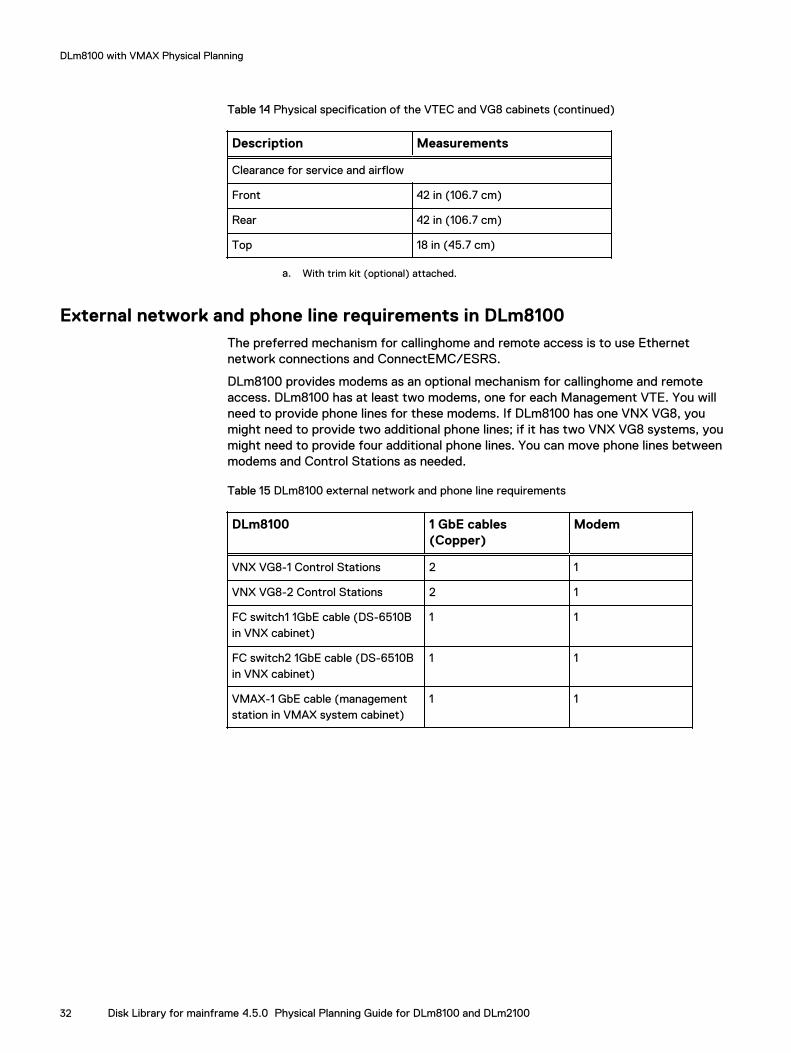
Table 14 Physical specification of the VTEC and VG8 cabinets (continued)
Description Measurements
Clearance for service and airflow
Front 42 in (106.7 cm)
Rear 42 in (106.7 cm)
Top 18 in (45.7 cm)
a. With trim kit (optional) attached.
External network and phone line requirements in DLm8100The preferred mechanism for callinghome and remote access is to use Ethernetnetwork connections and ConnectEMC/ESRS.
DLm8100 provides modems as an optional mechanism for callinghome and remoteaccess. DLm8100 has at least two modems, one for each Management VTE. You willneed to provide phone lines for these modems. If DLm8100 has one VNX VG8, youmight need to provide two additional phone lines; if it has two VNX VG8 systems, youmight need to provide four additional phone lines. You can move phone lines betweenmodems and Control Stations as needed.
Table 15 DLm8100 external network and phone line requirements
DLm8100 1 GbE cables(Copper)
Modem
VNX VG8-1 Control Stations 2 1
VNX VG8-2 Control Stations 2 1
FC switch1 1GbE cable (DS-6510Bin VNX cabinet)
1 1
FC switch2 1GbE cable (DS-6510Bin VNX cabinet)
1 1
VMAX-1 GbE cable (managementstation in VMAX system cabinet)
1 1
DLm8100 with VMAX Physical Planning
32 Disk Library for mainframe 4.5.0 Physical Planning Guide for DLm8100 and DLm2100

Figure 3 DLm8100 dual VG8 cabinet
Note
Refer to the EMC Symmetrix VMAX 20K/VMAX Series Physical Planning Guide [P/N300-008-601] for information about the VMAX cabinet.
DLm power requirementsThis section describes the North American electrical specifications, power cables,connectors, and extension cords for the VTEC and VG8 cabinets in a DLmconfiguration. The EMC VMAX 20K/VMAX Series Physical Planning Guide providesfurther information about power requirements for VMAX system and storage cabinets.
The table below summarizes the North American, single-phase, electricalspecifications power requirements specific to a single VTEC or VG8 cabinet.
Table 16 North American, single-phase, electrical specifications
Specification Requirements
Input voltage 200 V AC to 240 V AC -10%/+10% single-phase
Frequency 50 Hz to 60 Hz
Circuit breakers 30 A
Power zones Two
Power requirements at customer site (for eachcabinet)
Two single-phase drops each for: DLm8100 VTEC cabinetand VNX VG8 cabinet with up to one fully-loaded VG8 (8DMs)
Power distribution panel connectors NEMA L6-30P, and the Facility power mating receptacleis L6-30R
DLm8100 with VMAX Physical Planning
DLm power requirements 33
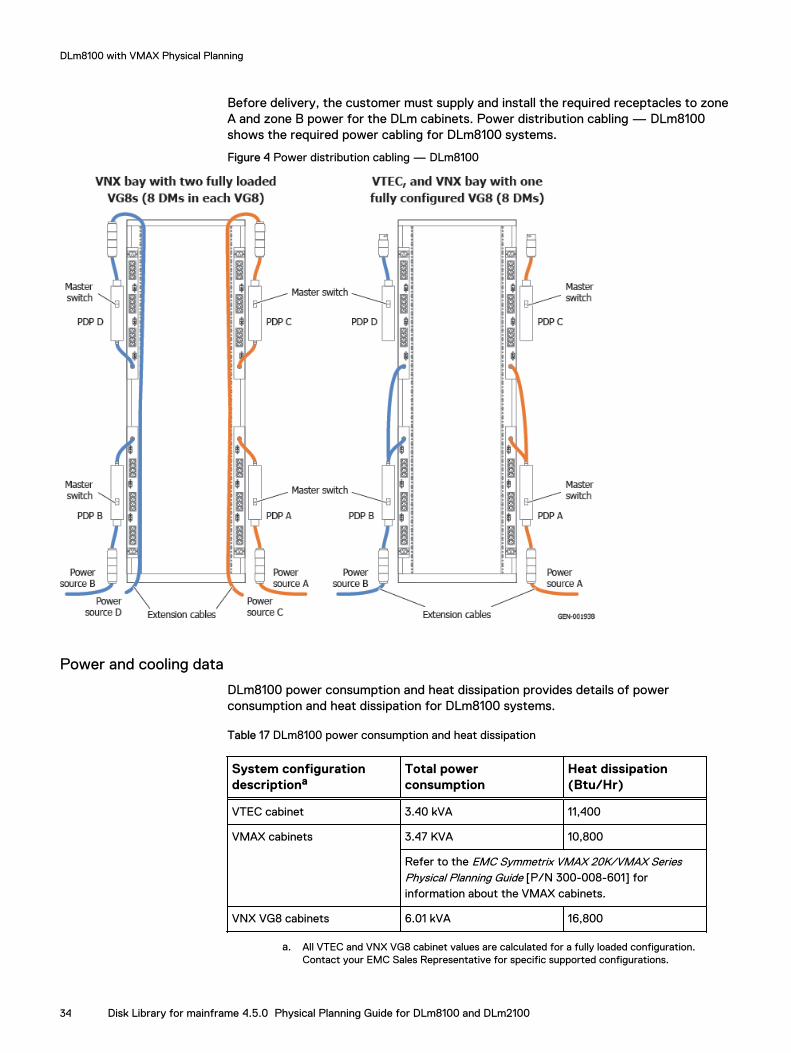
Before delivery, the customer must supply and install the required receptacles to zoneA and zone B power for the DLm cabinets. Power distribution cabling — DLm8100shows the required power cabling for DLm8100 systems.
Figure 4 Power distribution cabling — DLm8100
Power and cooling data
DLm8100 power consumption and heat dissipation provides details of powerconsumption and heat dissipation for DLm8100 systems.
Table 17 DLm8100 power consumption and heat dissipation
System configurationdescriptiona
Total powerconsumption
Heat dissipation(Btu/Hr)
VTEC cabinet 3.40 kVA 11,400
VMAX cabinets 3.47 KVA 10,800
Refer to the EMC Symmetrix VMAX 20K/VMAX SeriesPhysical Planning Guide [P/N 300-008-601] forinformation about the VMAX cabinets.
VNX VG8 cabinets 6.01 kVA 16,800
a. All VTEC and VNX VG8 cabinet values are calculated for a fully loaded configuration.Contact your EMC Sales Representative for specific supported configurations.
DLm8100 with VMAX Physical Planning
34 Disk Library for mainframe 4.5.0 Physical Planning Guide for DLm8100 and DLm2100
CHAPTER 5
DLm2100 with Data Domain or CloudArrayPhysical Planning
This chapter covers the tasks to be completed when planning an installation of theDLm2100 with Data Domain and/or CloudArray at the customer site.
l Overview of DLm2100........................................................................................36l DLm2100 Physical specifications....................................................................... 36l Power requirements for DLm2100......................................................................37
DLm2100 with Data Domain or CloudArray Physical Planning 35
Overview of DLm2100DLm2100 is a tape-on-disk controller. It emulates up to 256 drives. Data written to orread from these tape drives by the mainframe is stored and retrieved from a disksubsystem attached to the controller.
The tape data is stored in disk files that correspond to physical volumes of tape, with asingle file holding the data for one tape volume. The files are identified and correlatedto a volume by the tape Volume Serial Number (VOLSER), which is acquired from theLoad Display command sent from the host whenever it wants a tape volume to bemounted for reading or writing.
The DLm2100 consists of a single controller plus one or two storage options. Thestorage option may be shared with another DLm2100. The DLm2100 supports one ofthe following storage options:
l One Data Domain
l One CloudArray
l One Data Domain and one CloudArray
The Data Domain/CloudArray storage system may be one of several different systemscurrently supported. This planning guide only covers the DLm2100 controller.Information regarding the specific storage system must be obtained separately.
DLm2100 with Data DomainDLm combined with Data Domain offers deduplication features that deliver theaggregate throughput performance needed for enterprise data centers. This model'sin-line deduplication provides the most efficient solution for storing virtual tapes forbackup and archive applications. This results in lower storage costs and efficient useof replication links as only the unique data is transported between the sites.
DLm2100 with CloudArrayThe CloudArray appliance attached to a DLm provides a cloud gateway that makescloud storage look like NAS storage to the DLm VTE. A DLm2100 with CloudArrayallows you to schedule and maintain pointer-driven, in-cloud snapshots of your datafor greater protection.
DLm2100 Physical specificationsThis section cover the physical specifications for the DLm2100.
Physical dataThe DLm2100 is a 2U (3.5" high) rack-mountable system. The DLm is designed to beinstalled into an industry standard 19" RETMA cabinet. When fully configured, theweight of the DLm2100 system is 59 lb (27 kg). DLm2100 is shipped with a field installkit that includes rails. Identify the cabinet in which you will install the DLm, follow theinstructions that accompanied rail kit to mount rail into you cabinet, and then mountthe DLm onto the rails.
DLm2100 with Data Domain or CloudArray Physical Planning
36 Disk Library for mainframe 4.5.0 Physical Planning Guide for DLm8100 and DLm2100

External network and phone line requirementsDLm2100 has two 1 GbE ports, which should be connected to your organization'snetwork. The cables to connect these ports to your network are not supplied withDLm. Therefore, you should provide two network cables per DLm2100.
DLm2100 provides a modem as an optional mechanism for calling home and remoteaccess. (The EMC-recommended mechanism is to use ConnectEMC/ESRS.)
Each DLm2100 requires:
l Two 1 GbE network cables
l One phone line
Shipping dimensionsThe DLm2100 ships in a box with the dimensions of 37.8 in x 23.0 in x 11.7 in (96.0cm x58.5 cm x 29.8 cm).
System placementBoth the DLm2100 and the storage system are designed to install into an industrystandard 19" RETMA cabinet. Rack-mounting rails are provided with the DLm2100. If acabinet was not purchased with the DLm2100 or the storage system, you must provideone. A large system may consist of two cabinets which should be placed side by side.
You can install the system on a solid floor or a raised floor. Although not required, araised floor environment is preferred.
Power requirements for DLm2100This section describes the North American electrical specifications, power cables,connectors, and extension cords for a DLm configuration. The following tablesummarizes the power requirements.
Table 18 Power Requirements
Specification Requirements
Input voltage 90 - 264 V AC
Frequency 47 - 63 Hz
Power cords Two
Note
For required power drops, refer to the Power Calculator at https://powercalculator.emc.com and to any applicable documentation.
Power and cooling dataThe power consumption and heat dissipation for a single DLm2100 server (excludingthe attached storage system):
l Total power consumption is 0.36kVA
DLm2100 with Data Domain or CloudArray Physical Planning
External network and phone line requirements 37

l Heat dissipation is 1,100 Btu/Hr
The power consumption and heat dissipation for a single DLm2100 system, including aData Domain/CloudArray system varies greatly depending on which storage systemmodel is configured.
For example:
l Total power consumption of 2.29kVA (DLm2100 with DD2500) to 7.12kVA(DLm2100 with DD7200)
l Heat dissipation of 7,000 Btu/hr (DLm2100 with DD2500) to 20,900Btu/hr(DLm2100 with DD7200)
These values are calculated for a fully loaded configuration. Contact your EMC SalesRepresentative for specific supported configurations.
DLm2100 with Data Domain or CloudArray Physical Planning
38 Disk Library for mainframe 4.5.0 Physical Planning Guide for DLm8100 and DLm2100

CHAPTER 6
Environmental specifications and regulatorycompliance
This chapter discusses the environmental specifications and regulatory requirementscommon to all DLm models.
l Environmental specifications..............................................................................40l Regulatory compliance....................................................................................... 41l DLm touch current compliance.......................................................................... 42l Choosing a UPS................................................................................................. 42
Environmental specifications and regulatory compliance 39

Environmental specificationsThe following table provides the environmental specifications for the DLm system.
Table 19 DLm environmental data
Condition Limits
Operating temperature 50°F – 90°F (10°C to 32°C)
Operating altitude (at 32°) 7500 ft (2286 m)
Operating altitude (maximum) 10,000 ft (3048 m) 1.1° derating per 1000 ft
Operating humidity 20% to 80% non-condensing
Raised floor environment - for DLm8100 only Recommended but not required
Air flowThe following table lists the required environmental conditions during shipping andstorage of the DLm system.
Note
The air flow direction for cooling the systems should be from front to rear.
Table 20 Environmental requirements for shipping and storage
Condition Setting
Ambient temperature -40°F to 149°F (-40°C to 65°C)
Temperature gradient 43.2°F/hr (24°C/hr)
Relative humidity 10% to 90% non-condensing
Maximum altitude 35000 ft (10667.6 m)
Environment acclimationA DLm system requires time to get acclimated to a computer room environmentbefore and after you unpack it. Before unpacking the unit, allow it to stabilize for 16hours. After unpacking the unit, do not connect it to AC power for at least the numberof hours specified in the below table.
Table 21 Environmental acclimation
Transit / storage environment Hoursrequiredbeforeapplyingpower(minimum)
Condition (°F) (°C) %RH
Nominal 68–72 20–22 <30% 0 – 1
Environmental specifications and regulatory compliance
40 Disk Library for mainframe 4.5.0 Physical Planning Guide for DLm8100 and DLm2100

Table 21 Environmental acclimation (continued)
Transit / storage environment Hoursrequiredbeforeapplyingpower(minimum)
Condition (°F) (°C) %RH
Cool/Damp <68 <20 >30% 4
Cold/Dry <68 <20 <30% 4
Hot/Dry 72–149 22–65 <30% 4
Hot/Humid 72–149 22–65 30–45% 4
72–149 22–65 45–60% 8
72–149 22–65 60–90% 16
Note
The system's environment must have temperature and humidity values that preventcondensation from occurring on any system part. Altitude and atmospheric pressurespecifications are referenced to a standard day at 58.7°F (14.8°C). Maximum wetbulb temperature is 82°F (28°C).
Regulatory complianceDLm meets regulatory requirements as referenced by the following UL/IEC/EN 609503rd Edition:
5.1.7 Equipment with touch (leakage) current exceeding 3.5mA.
For Stationary Permanently Connected Equipment, or Stationary PluggableEquipment Type B, having a main protective earthing terminal, if the Touch (Leakage)Current measurements exceed 3.5mA r.m.s., following conditions apply:
l The r.m.s. Protective Conductor Current will not exceed five percent of the inputcurrent per line under normal operating conditions. If the load is unbalanced, thelargest of the single-phase currents shall be used for this calculation.
To measure the Protective Conductor Current, the procedure for measuringTouch Current is used, but the measuring instrument is replaced by an ammeter ofnegligible impedance.
l The cross-sectional area of the Protective Bonding Conductor will not be less than1.0 mm squared in the path of high Protective Conductor Current.
l A label with wording similar to the following shall be affixed adjacent to theequipment AC MAINS SUPPLY connection:
HIGH LEAKAGE CURRENT
Earth connection essential
before connecting supply
The DLm configurations are Stationary Pluggable Type B systems, and the applicationof the warning label, EMC P/N 046-000-309, are in English and French. The labellocation for the DLm configuration is on the inside of the front door.
Environmental specifications and regulatory compliance
Regulatory compliance 41
DLm touch current complianceDLm is designated as a fixed (stationary) electrical equipment with high earth-leakagemarkings. Connect the cabinets to the AC supply with the recommended rated currentbreakers and the attached cables. DLm power requirements on page 33 providesdetails of the recommended circuit breaker ratings. These recommended breakerratings are based on the maximum kW loading of the cabinet and not on the kVAfigures of a particular configuration. The kVA values listed in this manual are intendedfor air conditioning and utility loading purposes only. Power and cooling data on page26 contains detailed information.
CAUTION
Do not connect the DLm VTEC cabinet power supplies on separate Main andAuxiliary circuit panels to differential trip devices. These devices are typicallycalled Ground Fault Circuit Interrupter (GFCI), Ground Fault Interrupter (GFI),Earth Leakage Circuit Breaker (ELCB), or Residual Current Circuit Breakers.
Because DLm systems are high earth-leakage devices, differential trip devices(typically 30 mA) are not recommended due to random activation during utility feeddistortions and power line transients interacting with the cabinet noise filters. Thesedifferential devices have trip ratings of 5 mA to 500 mA and are mostly intended forconsumer goods rather than fixed devices.
If the DLm cabinet is correctly grounded to the AC power source, leakage current willnot produce a voltage leading to electrical shock. Serious insulation breakdowns willtrip the breakers feeding the cabinet or, preferably first clear fuses in individualinternal modules closest to the fault.
Choosing a UPSThe VTEC and Storage Controllers (Data Movers) are stateless, so no battery backupis required. In the event of a power failure, the Storage Processor writes contents ofthe write cache to disk, before shutdown. Although DLm does not require a batterybackup to ensure data integrity, to avoid potential downtime, purchase a UPS from aqualified vendor.
EMC neither offers nor recommends any specific UPS suppliers or product type to itscustomers. However, EMC uses preferred suppliers for UPS systems in their facilities.Therefore, if you, the customer, are implementing a UPS, EMC recommends thefollowing:
l When you are planning the UPS solution for a DLm and the host system ispresently (or will potentially be) protected with a UPS, the battery backup timeyou propose for the DLm UPS solution should match that of the host system.
l The DLm requires independent zone B and zone A power feeds for each cabinet.
l The UPS should be equipped with an internal output isolation transformer.
l The UPS should be installed as a separately derived AC source using neutral andground wiring to preserve the fault tolerance specification of the DLm powersystem.
l Depending on the power requirements for your DLm system operation, an isolationtransformer/stabilizer installed in front of the UPS could further buffer the AC
Environmental specifications and regulatory compliance
42 Disk Library for mainframe 4.5.0 Physical Planning Guide for DLm8100 and DLm2100
utility environmental factors from reaching DLm. To determine if an isolationtransformer/stabilizer is needed, consult a licensed electrician.
Environmental specifications and regulatory compliance
Choosing a UPS 43

Environmental specifications and regulatory compliance
44 Disk Library for mainframe 4.5.0 Physical Planning Guide for DLm8100 and DLm2100

APPENDIX A
DLm8100 System Service Area and Removal
This section provides service area dimensions, shipping information system placementand then removal.
l Dimensions and service area.............................................................................. 46l Shipping dimensions and clearance requirements.............................................. 46l System placement............................................................................................. 48l Package Removal...............................................................................................50
DLm8100 System Service Area and Removal 45

Dimensions and service areaBecause DLm cabinets ventilate through the rear, you must provide adequateclearance to service and cool the system, as illustrated in the next diagram.
Figure 5 DLm8100 cabinet dimensions and access area
GEN-001156
Height76.66 in.(194.7 cm)
Depth41.88 in.(106.4 cm)
Width24.02 in.(61.0 cm)
EMC Disk Library for mainframe cabinet
Rear access42.00 in.(106.7 cm)
Front access42.00 in.(106.7 cm)
EMCDisk Library for mainframecabinet
Top access18.0 in.(45.7 cm)
Shipping dimensions and clearance requirementsDLm8100 VTEC cabinets and VNX VG8 cabinets have the same dimensions. Thissection provides the dimensions, clearances, and placement of the VTEC and the VG8cabinets.
See EMC Symmetrix VMAX 20K/VMAX Series Physical Planning Guide for dimensions,clearances, and placement of the VMAX cabinets.
Note
Read the entire procedure before unpacking.
Ensure that your doorways and elevators are adequately wide and tall enough toaccommodate the shipping pallet and cabinet as shown in the below figure.
DLm8100 System Service Area and Removal
46 Disk Library for mainframe 4.5.0 Physical Planning Guide for DLm8100 and DLm2100
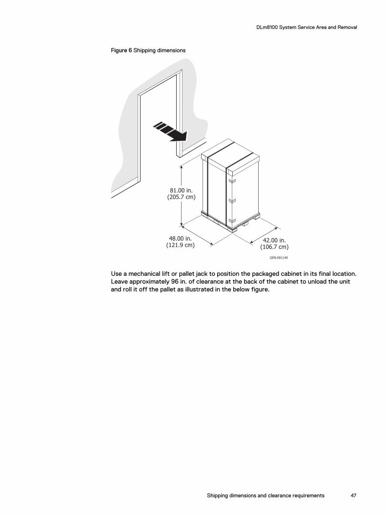
Figure 6 Shipping dimensions
48.00 in.(121.9 cm)
42.00 in.(106.7 cm)
81.00 in.(205.7 cm)
GEN-001140
Use a mechanical lift or pallet jack to position the packaged cabinet in its final location.Leave approximately 96 in. of clearance at the back of the cabinet to unload the unitand roll it off the pallet as illustrated in the below figure.
DLm8100 System Service Area and Removal
Shipping dimensions and clearance requirements 47

Figure 7 Unloading the pallet
System placementYou can install a DLm system on a solid floor or a raised floor.
Although not required, the raised floor environment is preferred.
DLm8100 configuration floor cutoutsDLm8100 supports a maximum of 15 cabinets with two fully configured VNX7500 orVNX7600 systems and two DD990, DD7200, or DD9500 systems. The following figureillustrates the configuration and the recommended floor tile cutouts for the DLm8100configuration. The illustrations assume that the floor tiles are 24 x 24 in. (61 x 61 cm).
DLm8100 System Service Area and Removal
48 Disk Library for mainframe 4.5.0 Physical Planning Guide for DLm8100 and DLm2100
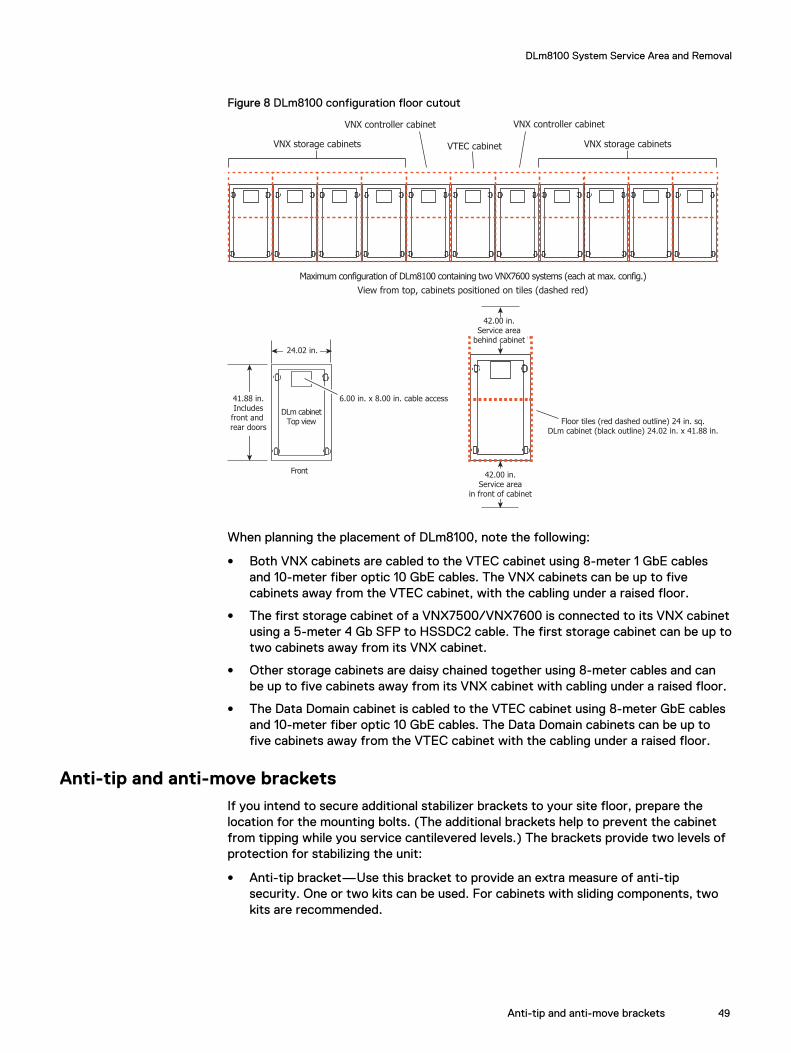
Figure 8 DLm8100 configuration floor cutout
Maximum configuration of DLm8100 containing two VNX7600 systems (each at max. config.)
View from top, cabinets positioned on tiles (dashed red)
VNX storage cabinetsVNX storage cabinets VTEC cabinet
VNX controller cabinet VNX controller cabinet
Floor tiles (red dashed outline) 24 in. sq.DLm cabinet (black outline) 24.02 in. x 41.88 in.
42.00 in.Service area
in front of cabinet
42.00 in.Service area
behind cabinet
24.02 in.
41.88 in.Includes
front and rear doors
Front
DLm cabinetTop view
6.00 in. x 8.00 in. cable access
When planning the placement of DLm8100, note the following:
l Both VNX cabinets are cabled to the VTEC cabinet using 8-meter 1 GbE cablesand 10-meter fiber optic 10 GbE cables. The VNX cabinets can be up to fivecabinets away from the VTEC cabinet, with the cabling under a raised floor.
l The first storage cabinet of a VNX7500/VNX7600 is connected to its VNX cabinetusing a 5-meter 4 Gb SFP to HSSDC2 cable. The first storage cabinet can be up totwo cabinets away from its VNX cabinet.
l Other storage cabinets are daisy chained together using 8-meter cables and canbe up to five cabinets away from its VNX cabinet with cabling under a raised floor.
l The Data Domain cabinet is cabled to the VTEC cabinet using 8-meter GbE cablesand 10-meter fiber optic 10 GbE cables. The Data Domain cabinets can be up tofive cabinets away from the VTEC cabinet with the cabling under a raised floor.
Anti-tip and anti-move bracketsIf you intend to secure additional stabilizer brackets to your site floor, prepare thelocation for the mounting bolts. (The additional brackets help to prevent the cabinetfrom tipping while you service cantilevered levels.) The brackets provide two levels ofprotection for stabilizing the unit:
l Anti-tip bracket—Use this bracket to provide an extra measure of anti-tipsecurity. One or two kits can be used. For cabinets with sliding components, twokits are recommended.
DLm8100 System Service Area and Removal
Anti-tip and anti-move brackets 49

Figure 9 Rack measurements for anti-tip brackets
EMC2853
61.00
42.56 7.00
17.25
21.25
2.78
3.39
.438
7.00
All m easurem ents are in inches.
Front
Rear
1.56
l Anti-move bracket —Use this bracket to permanently fasten the unit to the floor.
Figure 10 Rack measurements for anti-move brackets
42.88
40.88
16.92
21.258.46
.502.00
3.55
.438
EMC2854
Front
Rear
All m easurem ents are in inches.
If your system will be secured by one or more of these anti-tip brackets, ensure thatthe cabinet is in its final location before attaching them. Use the supplied bolts andmounting holes to fasten the bracket to the cabinet and floor. (The additional bracketshelp to prevent the cabinet from tipping while you service devices on slide rails.)
The 40U-C Cabinet Unpacking and Setup Guide provides information about installing theanti-tip and anti-move brackets.
Package RemovalThis section describes the procedures for inspecting and then unpacking the DLm8100cabinets.
DLm8100 System Service Area and Removal
50 Disk Library for mainframe 4.5.0 Physical Planning Guide for DLm8100 and DLm2100
Inspect the system shipmentInspect the outer packaging for signs of possible shipping damage. If you notice visibledamage:
Procedure
1. Note the damage on the waybill.
2. Photograph the damage.
3. Notify the EMC Traffic department and Customer Support management.
4. File a freight claim with the carrier.
Unpacking procedureBefore unpacking the unit, allow it to stabilize for 16 hours.
CAUTION
Before moving the unit over a raised floor, ensure that the floor meets therequirements listed under System placement on page 48.
Follow these steps to unload and unpack the cabinets:
Procedure
1. Use a mechanical lift or pallet jack to position the packaged cabinet in its finallocation.
Note
Before placing the cabinets, note the correct placement (based on the overallsystem configuration) and the floor tile cutouts to place each cabinet.
Leave approximately 96 in. of clearance at the back of the cabinet to unload thecabinet and roll it off the pallet.
2. Remove the shipping material:
a. Cut the tape and straps that hold the cardboard carton together asillustrated in the next diagram.
DLm8100 System Service Area and Removal
Inspect the system shipment 51

Figure 11 Cutting the tape and straps
EMC2838
b. Remove the cardboard packing hood and wraparound sleeve as illustrated inthe next diagram.
Figure 12 Removing the packing material of the cabinet
SYM-000862
c. Cut the wrap strap that secures the plastic shipping bag around the cabinet.
DLm8100 System Service Area and Removal
52 Disk Library for mainframe 4.5.0 Physical Planning Guide for DLm8100 and DLm2100
The 40U-C Cabinet Unpacking and Setup Guide provides information aboutunpacking and setting up the DLm hardware.
Note
After unpacking the unit, allow it to stabilize in the new environment asspecified in Environment acclimation on page 40. EMC recommends that youopen both the front and the rear doors to facilitate environmental acclimation.
DLm8100 System Service Area and Removal
Unpacking procedure 53

DLm8100 System Service Area and Removal
54 Disk Library for mainframe 4.5.0 Physical Planning Guide for DLm8100 and DLm2100
APPENDIX B
Inspecting and Unpacking the DLm2100 DDSystem
This section describes the procedures for inspecting, unpacking and positioning theDLm2100 DD system.
l Inspect the system shipment............................................................................. 56l Unpacking procedure......................................................................................... 56l DLm2100 configuration floor cutout...................................................................56
Inspecting and Unpacking the DLm2100 DD System 55
Inspect the system shipmentInspect the outer packaging for signs of possible shipping damage. If you notice visibledamage:
Procedure
1. Note the damage on the waybill.
2. Photograph the damage.
3. Notify the EMC Traffic department and Customer Support management.
4. File a freight claim with the carrier.
Unpacking procedure
Note
Before unpacking the DLm2100, allow it to stabilize for 16 hours.
CAUTION
Lifting the DLm2100 from the box requires two people.
Follow these steps to unpack the box.
Procedure
1. Locate the box in close proximity to the cabinet in which the DLm2100 will bemounted.
2. Remove the server from the shipping box.
a. Cut the tape that holds the top flaps of the box together.
b. Open the box and remove the large flat cardboard box on top.
c. Remove the foam packing material.
d. Fold over the cardboard flaps to create two hand-holds on each side of theDLm2100.
e. You need the help of another person to lift the DLm2100 from the box. Witheach person holding two handholds, lift the DLm2100 out of the box shippingbox.
3. After removing the DLm2100 from its shipping box, mount it in a cabinet.
DLm2100 configuration floor cutoutThe following Figure illustrates the configuration and the recommended floor tilecutouts for the DLm2100 configuration. The illustrations assume that the floor tiles are24 x 24 in. (61 x 61 cm).
Inspecting and Unpacking the DLm2100 DD System
56 Disk Library for mainframe 4.5.0 Physical Planning Guide for DLm8100 and DLm2100

Figure 13 DLm2100 configuration floor cutout
GEN-001149
41.88 in.Includesfront and rear doors
8.00 in.
6.00 in.
24.02 in.
42.00 in.Service area
42.00 in.Service area
Inspecting and Unpacking the DLm2100 DD System
DLm2100 configuration floor cutout 57

Inspecting and Unpacking the DLm2100 DD System
58 Disk Library for mainframe 4.5.0 Physical Planning Guide for DLm8100 and DLm2100