Discussion on regional radar network and radar exchange€¦ · WMO/ASEAN Training Workshop on...
76
WMO/ASEAN Training Workshop on Weather Radar Data Quality and Standardization Japan Radio Co., Ltd Bangkok, Thailand, 5-13 February 2018 6th February 2018 Shuichi Inoue General Manager Business Development Department Japan Radio Co., Ltd. Discussion on regional radar network and radar exchange (Weather Radar Maintenance)
Transcript of Discussion on regional radar network and radar exchange€¦ · WMO/ASEAN Training Workshop on...

WMO/ASEAN Training Workshop on Weather Radar Data Quality and Standardization
Japan Radio Co., Ltd Bangkok, Thailand, 5-13 February 2018
6th February 2018
Shuichi InoueGeneral Manager
Business Development DepartmentJapan Radio Co., Ltd.
Discussion on regional radar network and radar exchange
(Weather Radar Maintenance)

WMO/ASEAN Training Workshop on Weather Radar Data Quality and Standardization
Japan Radio Co., Ltd Bangkok, Thailand, 5-13 February 2018
Operation and Maintenance of the Meteorological Radar
1. Relation of maintenance and radar equation Radar equation considering Z-R relation ReflecƟon intensity(dBZ) → PrecipitaƟon intensity (mm/h)
Conversion
2. Various maintenance items for the radar equipment The Purpose of Periodic Maintenance and Calibration Periodic Maintenance for Each Equipment (Daily, Weekly, Monthly,
6 Monthly)
3. Caution point Basic precautions Caution for using the test instruments Precautions for handling special tubes Cleaning and Check
2

WMO/ASEAN Training Workshop on Weather Radar Data Quality and Standardization
Japan Radio Co., Ltd Bangkok, Thailand, 5-13 February 2018
What is radar?
MeasurementΔt, AZ, EL, Pr, fd
RADAR: Radio Detection And RangingTarget:Precipitation drops
Radar site
Transmitted pulse
reflected pulserain
○ Pr : receivedpower
Radar equation Pr =( Rc・Z / r2)・10-0.2・kg・r
Z : radar reflectivity factorRc : radar constant
Z-R relationZ = B・Rβ rain rate
○ fd : doppler frequencyV= fd・λ/ 2V : Doppler velocityλ:wave length
air flow withinprecipitation area
○ Δt : time of each pulse propagation
Δt=2r / cc: light velocity
r = cΔt / 2 distance betweenradar and target
distribution of the precipitation
○ AZ, EL, r Direction and height of the target
3

WMO/ASEAN Training Workshop on Weather Radar Data Quality and Standardization
Japan Radio Co., Ltd Bangkok, Thailand, 5-13 February 2018
Periodic Maintenance Items● Antenna and Antenna Controller Specifications
(1) Type 4 m in Diameter Parabolic Dish Antenna(2) Gain More than 42 dB(3) Beam Width less than 1.2 degrees(4) Polarization Horizontal(5) Rotation Speed 4 rpm +/- 5 %(6) EL Angle Range -2 to +45 degreesLower 1st limit: -3 degreesLower 2nd limit: -5 degreesUpper 1st limit: +46 degreesUpper 2nd limit: +48 degrees
4
2
112
02t
10
3
21 GhP
2log2 Rc
ε
εφθ
λ
π
e

WMO/ASEAN Training Workshop on Weather Radar Data Quality and Standardization
Japan Radio Co., Ltd Bangkok, Thailand, 5-13 February 2018
dBZ・mm/h
In Japan, B = 200 and β = 1.6 are adopted.
(Z: mm6/m3, R: mm/h)
- Precipitation intensity(mm/h) → ReflecƟon intensity (dBZ) Conversion
- Reflection intensity(dBZ) → PrecipitaƟon intensity (mm/h) Conversion
mm/h)intensity( ionPrecipitat16log23mm/h)intensity( ionPrecipitat16log)200(10log
mm/h)intensity( ionPrecipitat20010log
)(log10log10 dBz)intensity Reflection
10
1010
1.610
1010
RBZ ・(
1623-dBz)intensity( Reflection
10mm/h)intensity( ionPrecipitat
RBZ
5

WMO/ASEAN Training Workshop on Weather Radar Data Quality and Standardization
Japan Radio Co., Ltd Bangkok, Thailand, 5-13 February 2018
Z – R Relation
Ⅰ: Scattered but somewhat heavy portion of thunderstorm echo, or high, isolated, convective echo in dry atmospheric air (water drops evaporate considerably). Ⅱ: Center portion where thunderstorm echo is dominant, or strong, massive echo with slightly scattered shape.Ⅲ: Breaking out or growing stage of the convective cells.Ⅳ: Small, solid-like, convective echoes scattered or aligned.Ⅴ: Stratiform echoes uniformly spread, or scattered weak echoes.Ⅵ: Final stage of thunderstorm completely scattered, or scattered portions.
Type of rain B β
JMA 200 1.6 0.50 1.0 4 16 64 256
Ⅱ 400 1.3 0.25 0.6 3.2 18 98 540
(Convective) 50% 59% 81% 111% 153% 211%
Ⅴ 130 1.7 0.67 1.3 4.8 18 65 238
(Stratiform) 134% 129% 119% 109% 101% 93%
Weak ← The strength of the rain [mm/h] → Strong
Comparison of rainfall when using B and β of JMA standard, Ⅱ, Ⅴ in the figure on the right.Showing percentages are comparison with JMA standard.
The relation between radar reflectivity factor Z andrain rate R [mm/h] is expressed statistically as follows :
Z = BRβ
(rain) B:80~1000 (snow) B:500~2000β:1.0~2.0 β:2.0
6

WMO/ASEAN Training Workshop on Weather Radar Data Quality and Standardization
Japan Radio Co., Ltd Bangkok, Thailand, 5-13 February 2018
To achieve a certain level of data quality
To keep to the regulations Quality of radio wave from radar is regulated by
the Radio Law and related regulations.
In order to prevent critical failure in radar system and equipment
The Purpose of Periodic Maintenance and Calibration
7Radar Failure Modes: Results from the WMO Weather Radar Survey showing the mainfailure modes of a radar (2010)

WMO/ASEAN Training Workshop on Weather Radar Data Quality and Standardization
Japan Radio Co., Ltd Bangkok, Thailand, 5-13 February 2018
Radar Calibration
2.Absolute calibration: Using measurements of AZ scan at 90°EL and disdrometer measurements at the radar sites.
3.System differential offsets of ZDR and φDP: Using measurements of an operational AZ scan at 90°EL.
1.Solar flux measurement:Monitoring the receiver sensitivity, differential offset of the receive path (ZDR), antennapointing accuracy, beam squint.
AZ Scan at 90°EL
The key assumption of the method is thatZDR is zero when looking at falling raindrops from below.
Disdrometer
The difference is that only range bins are considered where we have Zh > 20 dBZ and ρhv> 0.98.
650m
10m
One rangebin in the far-field
The ZDR offset is currently a static offset which has to beset manually. It is part of a list of processing parameters needed by the signal processor to compute ZDR.

WMO/ASEAN Training Workshop on Weather Radar Data Quality and Standardization
Japan Radio Co., Ltd Bangkok, Thailand, 5-13 February 2018
1. Periodic maintenance is really important not only keeping a good condition of the radar system but also keeping a good quality of the radar data.
2. Carrying out a periodic maintenance is very useful to understand the current condition of the radar system.
3. The radar system should be checked and maintained periodically as daily, weekly, monthly and 6 monthly.
4. For daily inspection, it is carried out through remote control from the central monitoring station.
5. For 6 monthly inspection, it is carried out in cooperation with a person in the radar management office and necessary to stop the regular observation for the monthly and 6 monthly check and maintenance
6. Results of the periodical maintenance must be recorded in the log book.
Periodic Maintenance of the Radar Equipment
9

WMO/ASEAN Training Workshop on Weather Radar Data Quality and Standardization
Japan Radio Co., Ltd Bangkok, Thailand, 5-13 February 2018
Daily Maintenance Items
Click
Check No RED Color Indicator

WMO/ASEAN Training Workshop on Weather Radar Data Quality and Standardization
Japan Radio Co., Ltd Bangkok, Thailand, 5-13 February 2018
Periodic Maintenance Items for Radome(1) Radome
Periodic Inspection and Maintenance Items Interval
Water Leaking (trace) in the radome 3
Panel surface
scratch, cracking, peeling, dirt 6
Panel joint caulking
peeling, cracking, dirt 6
Lightning rod and grounding cable 6
Aviation obstruction lights D
Panel surface cleaning 5 years
Interval= D: Daily, W: Weekly, 1: Monthly, 3: 3 Monthly, 6: 6 Monthly
11
Obstruction Light
Lightning Rod

WMO/ASEAN Training Workshop on Weather Radar Data Quality and Standardization
Japan Radio Co., Ltd Bangkok, Thailand, 5-13 February 2018
Periodic Maintenance Items for Antenna(2) Antenna (1/2)
Periodic Inspection and Maintenance Items Interval
Azimuth and elevation drive section
Motor, reducer, gear, brake 6
Motor brush, coupling or drive belt 6
Lubricant (grease, oil), leakage 6Slip-ring and brush
Contact surface of slip-ring and brush 1Brush powder, brush remaining 1
Rotary-joint and waveguide
Rotation sound, squeaking noise, rotation smoothness 6
Deformation, asperity, joint cracks, air leakage 6
Angle detector, Limit switch 6
Interval= D: Daily, W: Weekly, 1: Monthly, 3: 3 Monthly, 6: 6 Monthly
12

WMO/ASEAN Training Workshop on Weather Radar Data Quality and Standardization
Japan Radio Co., Ltd Bangkok, Thailand, 5-13 February 2018
Periodic Maintenance Items for Antenna(2) Antenna (2/2)
Periodic Inspection and Maintenance Items Interval
Operational status of azimuth and elevation section
Rotation sound, squeaking noise and rotation smoothness W
Rotation speed 6
Positioning accuracy MSafety function
Elevation limit operation 6Safety switch operation W
Calibration
Antenna level A
Antenna orientation A
Interval= D: Daily, W: Weekly, 1: Monthly, 3: 3 Monthly, 6: 6 Monthly, A: Annual
13

WMO/ASEAN Training Workshop on Weather Radar Data Quality and Standardization
Japan Radio Co., Ltd Bangkok, Thailand, 5-13 February 2018
Periodic Maintenance Items
Signal Flow between the Antenna and Antenna Control Unit
Elevation angle command signal
Emergency Stop
EL Angle detector
(Resolver)
EL drivemotor
ANT stopSW(Safety
switch)
EL angleconvertor
EL angledifferencedetection
EL motor driver(Servo Amp)
AntennaControl
Powersupply Power supply
ANTLimit SW
Antenna Controller
Limit signal
SW on
EL Overload
Feedback
Feedback
ElevationDrive
Section
14
Antenna
CurrentDetector
AZ angleconvertor
AZ angledifferencedetection
AZ motor driver(Servo Amp)
Power supply
CurrentDetector
Powersupply
Azimuth angle command signal
AZ Overload
AZ Angle detector
(Resolver)
AZ drivemotor
AzimuthDrive
Section

WMO/ASEAN Training Workshop on Weather Radar Data Quality and Standardization
Japan Radio Co., Ltd Bangkok, Thailand, 5-13 February 2018
Periodic Maintenance Items
Cross Section Of Reflecting Mirror
Drive Servo Motor
Angle detector(Resolver)
Wave Guide Wave Guide
Electric wire
Electric wire
Electric wire
Receiver Transmitter
ANTController
Transmission wave
Reception wave
Angle signal
Motor drive power
Transmission wave
Reception wave
Angle signalLimit signal
Motor drive power
Power and control signals are transmitted between the rotation-side slip ring and the fixed brush..
Slip-rings
Rotary-joint
Electromagnetic wave is transmitted to the rotating side from the fixed side.
ANTEL driver
15Rotary-joint and Slip-rings

WMO/ASEAN Training Workshop on Weather Radar Data Quality and Standardization
Japan Radio Co., Ltd Bangkok, Thailand, 5-13 February 2018
Periodic 1 month Maintenance Items
Slip ring
Brush
Clean the slip ring with dry soft cloth.
Open the Cover of the Slip ring & Brush (Front Side)

WMO/ASEAN Training Workshop on Weather Radar Data Quality and Standardization
Japan Radio Co., Ltd Bangkok, Thailand, 5-13 February 2018
EL oil outlet
AZ oil outlet AZ oil gaugePedestal AZ body
EL oil gauge
Oil gauge and Oil outlet
Periodic 6 month Maintenance Items
17
If oil level is low,
Reduction gear oil replacement
Grease Replenishment

WMO/ASEAN Training Workshop on Weather Radar Data Quality and Standardization
Japan Radio Co., Ltd Bangkok, Thailand, 5-13 February 2018
AZ drive belt
Azimuth and Elevation drive belt
EL drive belt
18
Periodic 6 month Maintenance Items

WMO/ASEAN Training Workshop on Weather Radar Data Quality and Standardization
Japan Radio Co., Ltd Bangkok, Thailand, 5-13 February 2018
Operation of Limit Switch
1st Limit Switch (lower)
1st Limit Switch (upper)2nd Limit Switch (lower)
2nd Limit Switch (upper)
EL Angle Detector
EL Axis
EL Angle Scale
19
Periodic 6 month Maintenance Items

WMO/ASEAN Training Workshop on Weather Radar Data Quality and Standardization
Japan Radio Co., Ltd Bangkok, Thailand, 5-13 February 2018
START STOP
Stopwatch(Smartphone)
Periodic 6 month Maintenance Items
Time measurement of one (1) rotation

WMO/ASEAN Training Workshop on Weather Radar Data Quality and Standardization
Japan Radio Co., Ltd Bangkok, Thailand, 5-13 February 2018
Periodic Maintenance Items for Antenna Controller
(3) Antenna Controller
Periodic Inspection and Maintenance Items Interval
Control function
Mode control 6
Position control 3
Rotation speed control 6Safety interlock and protection 6
Monitoring function
Antenna operating status, meter indication 1
Azimuth/elevation angle 1
Alarm information D
Interval= D: Daily, W: Weekly, 1: Monthly, 3: 3 Monthly, 6: 6 Monthly
21

WMO/ASEAN Training Workshop on Weather Radar Data Quality and Standardization
Japan Radio Co., Ltd Bangkok, Thailand, 5-13 February 2018
Daily Maintenance Items
Click
Check No RED Color Indicator

WMO/ASEAN Training Workshop on Weather Radar Data Quality and Standardization
Japan Radio Co., Ltd Bangkok, Thailand, 5-13 February 2018
Periodic Maintenance Items for Transmitter(4) Transmitter (1/2)
Periodic Inspection and Maintenance Items Interval
Transmitting operation
Peak power, frequency, spectrum, stability 1
Transmission pulse width, pulse repetition frequency 1
Transmission tube current, its waveform WModulator operating sound D
Monitoring function
Operating time indication of the transmission tube M
Modulator operating status, meter indication D
Alarm information D
Interval= D: Daily, W: Weekly, 1: Monthly, 3: 3 Monthly, 6: 6 Monthly
23

WMO/ASEAN Training Workshop on Weather Radar Data Quality and Standardization
Japan Radio Co., Ltd Bangkok, Thailand, 5-13 February 2018
Periodic Maintenance Items for Transmitter(4) Transmitter (2/2)
Periodic Inspection and Maintenance Items IntervalOperation
Operation mode control 6Temperature, cooling 3Safety interlock and protection 6
Parts condition
High voltage parts such as a coil, wiring inside in the modulator 6
Insulation oil level, insulation materials, bushes 6Air filter 3
Interval= D: Daily, W: Weekly, 1: Monthly, 3: 3 Monthly, 6: 6 Monthly
24

WMO/ASEAN Training Workshop on Weather Radar Data Quality and Standardization
Japan Radio Co., Ltd Bangkok, Thailand, 5-13 February 2018
Daily Maintenance Items
Click
Check No RED Color Indicator

WMO/ASEAN Training Workshop on Weather Radar Data Quality and Standardization
Japan Radio Co., Ltd Bangkok, Thailand, 5-13 February 2018
Transmitted frequency(One among from 5250 to 5370 MHz Wave length from 5.71 to 5.59 cm)
Pulse width (τ)2.5 μs
Peak power (Pt)250 kW
Pulse Repetition Frequency(number of pulses per 1 sec.): 260 Hz
(Review) Transmission Pulse of the Weather Radar(in case of Klystron, Magnetron type)
26
Pulse Interval(1/260Hz = 3846μs 576.9 km (round trip))
Pulse width (τ)2.5 μs
Peak power (Pt)250 kW

WMO/ASEAN Training Workshop on Weather Radar Data Quality and Standardization
Japan Radio Co., Ltd Bangkok, Thailand, 5-13 February 2018
Transmission Pulse of the Weather Radar(for SSPA type)
Chirp Pulse Chirp Pulse
Blind area (15km)
If it transmits a Long Pulse only

WMO/ASEAN Training Workshop on Weather Radar Data Quality and Standardization
Japan Radio Co., Ltd Bangkok, Thailand, 5-13 February 2018
Why does the Solid State Transmitter radiate a long pulse?
-Peak power : 500kw (Pulse width 2us)Minimum detectable rainfall precipitation : 1 mm/hr (at 450km)
Pulse width 2us 100us
- Solid State Type TransmitterPeak Power : 10kW
-Peak power : 10kw (Pulse width 2us)Minimum detectable rainfall precipitation : 12 mm/hr (at 450km)
-Peak power : 10kw (Pulse width 100us)Minimum detectable rainfall precipitation : 1 mm/hr (at 450km)
-Electronic Tube Type Transmitter Peak Power : 500kW
Problem!
Solution!
Pt ・h = 500kW・2us = 10kW・100us

WMO/ASEAN Training Workshop on Weather Radar Data Quality and Standardization
Japan Radio Co., Ltd Bangkok, Thailand, 5-13 February 2018
Periodic Maintenance Items● Transmitter Specifications (C-band, in Japan)
(1) Type Klystron tube (or Magnetron tube)(2) Transmission Frequency One among from 5250 to 5370 MHz(3) Transmission Peak Power 250 kW(4) Transmission Pulse WidthLong Range Mode: 2.5μs +20% -0%Doppler Mode: 1.0μs +20% -0%(5) Pulse Repetition Frequency Variable in 1500 Hz or lessLong Range Mode: 260 HzDoppler Mode: 330, 480, 600, 752 and 940 Hz(6) Modulator Solid-state type(not use the thyratron)
2
112
02t
10
3
21 GhP
2log2 Rc
ε
εφθ
λ
π
e
29

WMO/ASEAN Training Workshop on Weather Radar Data Quality and Standardization
Japan Radio Co., Ltd Bangkok, Thailand, 5-13 February 2018
Solid State Chirp Pulse Radar
■Receiver
+
Output
Delay
Multiplexer
Matched Filter
Frequency
Dela
yed
Tim
e
Time
Peak
Pow
er
Pulse CompressionChirp modulation pulse is transmitted.
■Transmitter
Transmitted pulse
Time
Freq
uenc
y
Modulated BW
Pulse Width
Chirp pulse
Linear Frequency Modulation(LFM)
WMO/ASEAN Training Workshop on Weather Radar Data Quality and Standardization
Japan Radio Co., Ltd Bangkok, Thailand, 5-13 February 2018
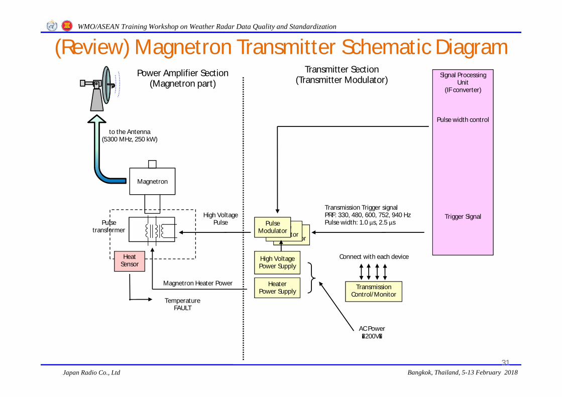
(Review) Magnetron Transmitter Schematic Diagram
31
Pulse Modulator
Transmission Trigger signalPRF: 330, 480, 600, 752, 940 HzPulse width: 1.0 μs, 2.5 μs
High Voltage Power Supply
AC Power(200V)
Transmission Control/Monitor
HeaterPower Supply
Heat Sensor
TemperatureFAULT
Transmitter Section(Transmitter Modulator)
to the Antenna(5300 MHz, 250 kW)
High Voltage Pulse
Magnetron Heater Power
Connect with each device
Magnetron
Power Amplifier Section(Magnetron part)
31
Signal Processing Unit
(IF converter)
Pulse width control
Trigger Signal
Pulse Modulator
Pulse Modulator
Pulsetransformer

WMO/ASEAN Training Workshop on Weather Radar Data Quality and Standardization
Japan Radio Co., Ltd Bangkok, Thailand, 5-13 February 2018
(Review) Klystron Transmitter Schematic Diagram
Mixer
STALO
StableOscillator(5330MHz)
Ion Pomp
Divider
to the Receiver
COHO
CoherentOscillator(30MHz)
DividerExciter
(Amplifier)
Transmission Signal(5300MHz)
Transmission Signal
(5300MHz)
5330 MHz - 30MHz
Pulse Modulator
Transmission Trigger signalPRF: 330, 480, 600, 752, 940 HzPulse width: 1.0 μs, 2.5 μs
High Voltage Power Supply
AC Power(200V)
Transmission Control/Monitor
HeaterPower Supply
Focus Coil Power Supply
Ion Pump Power Supply
Heat Sensor
TemperatureFAULT
Focus Coil
Pulsetransformer
Oil Tank
Transmitter Section(Transmitter Modulator)
to the Antenna(5300 MHz, 250 kW)
High Voltage Pulse
Klystron Heater Power
Connect with each device
Klystron
Power Amplifier Section(klystron part)
32
Signal Processing Unit
(IF converter)
Phase control Pulse width control
COHO signal
Trigger Signal
Pulse Modulator
Pulse Modulator

WMO/ASEAN Training Workshop on Weather Radar Data Quality and Standardization
Japan Radio Co., Ltd Bangkok, Thailand, 5-13 February 2018
Solid-state Transmitter Schematic Diagram(S-band)
DRSP

WMO/ASEAN Training Workshop on Weather Radar Data Quality and Standardization
Japan Radio Co., Ltd Bangkok, Thailand, 5-13 February 2018
Transmitting Frequency Measurement(in case of Magnetron, Klystron)
AttenuatorRF Pulse
FrequencyMeter
Transmittercable
* Connected to the terminal (monitor) TX RF MON of the transmission unit.
RF Pulse Frequency MeterTransmitter
Attenuator34

WMO/ASEAN Training Workshop on Weather Radar Data Quality and Standardization
Japan Radio Co., Ltd Bangkok, Thailand, 5-13 February 2018
Transmitting Frequency Measurement(In case of SSPA Type)
Spectrum Analyzer
TransmitterController
N cableTx RFRF IN 50Ω
Transmitting Frequency Measurement Connection DiagramSpectrum Analyzer
Short Pulse Long Pulse
Measurement of short pulse on the spectrum analyzer window
Adjust to the Center of this range

WMO/ASEAN Training Workshop on Weather Radar Data Quality and Standardization
Japan Radio Co., Ltd Bangkok, Thailand, 5-13 February 2018
RF detection waveformat 3 dB attenuation
The reference line(ex. Center line) -3dB
Average wave height
RF detection waveformat 0 dB attenuation
Find out the average wave height position visually
Defined at 3dB point decrease from the average wave height
Transmitting Pulse Width (τ)Measurement(In case of Klystron, Magnetron)
Ground Level
Pulse Width
36

WMO/ASEAN Training Workshop on Weather Radar Data Quality and Standardization
Japan Radio Co., Ltd Bangkok, Thailand, 5-13 February 2018
BNC adapter type T
Termination resistor forcrystal detector (50Ω)
Oscilloscope
Crystal detector[10dB]
[3dB]
Attenuator[10+20+3=33dB]
Transmitter Panel
[20dB]Cable with BNC-typeterminals (50Ω)
Trigger signal
37
Transmitting Pulse Width (τ)Measurement(In case of Klystron, Magnetron)

WMO/ASEAN Training Workshop on Weather Radar Data Quality and Standardization
Japan Radio Co., Ltd Bangkok, Thailand, 5-13 February 2018
【3 dB Attenuator】: Connect
Referenceline
1.12μS measurements
X2X1
Attenuator OscilloscopeTransmitter cable
* Connected to the terminal (monitor) TX RF MON of the transmitter.
detector
【3 dB Attenuator】: Disconnect
38
Transmitting Pulse Width (τ)Measurement(In case of Klystron, Magnetron)

WMO/ASEAN Training Workshop on Weather Radar Data Quality and Standardization
Japan Radio Co., Ltd Bangkok, Thailand, 5-13 February 2018
Transmitting Pulse Width (τ)Measurement(In case of SSPA Type)
Transmitting Pulse Width Measurement Connection Diagram
Connect another BNC cable between TX GATE monitor terminal of the controller and channel 2 of the oscilloscope.
Set the impedance of CH1 to 50Ω and CH2 to 1MΩ
Short Pulse
Short Pulse
(1)
Level A Level A
Pulse Width
POINT!!
Detector Waveform Shown on Oscilloscope (with 3db Attenuator)
Detector Waveform Shown on Oscilloscope (without 3db Attenuator)Detector waveform (CH-1) and TX GATE (trigger timing / CH-2)
will appear on the oscilloscope (Short Pulse)

WMO/ASEAN Training Workshop on Weather Radar Data Quality and Standardization
Japan Radio Co., Ltd Bangkok, Thailand, 5-13 February 2018
Transmitting Pulse Width (τ)Measurement(In case of SSPA Type)
Transmitting Pulse Width Measurement Connection Diagram
Detector waveform (CH-1) and TX GATE (trigger timing / CH-2) will appear on the oscilloscope (Long Pulse)
Adjust by “VER POSITION”
(1)
Level A Level A
Pulse Width
POINT!!
Remove the attenuator (3dB) and reconnect the crystal detector to TX RF monitor terminal of the controller.
As a result, the electric power will be increased by 3dB and the oscillation of the detector waveform will be amplified on the oscilloscope.

WMO/ASEAN Training Workshop on Weather Radar Data Quality and Standardization
Japan Radio Co., Ltd Bangkok, Thailand, 5-13 February 2018
Pulse Repetition Frequency (PRF) Measurement
Cycle time
Detecting waveform
41
(1)
v
v
v v
TPRF
“PRF-1”
Connecting diagram is same as measuring method for the pulse width (mentioned in the previous page).Measure the cycle time of crystal detecting waveform on the oscilloscope display.Then, calculate the PRF from cycle time.
PRF = 1 / cycle time
Detecting waveform< Using a oscilloscope >
PRF for SSPA PRF for Klystron, Magnetron
Transmitting Pulse Width Measurement Connection Diagram

WMO/ASEAN Training Workshop on Weather Radar Data Quality and Standardization
Japan Radio Co., Ltd Bangkok, Thailand, 5-13 February 2018
Transmitting Pulse Width Measurement Connection Diagram
For staggered mode (Doppler Mode), two (2) periods is displayed on the oscilloscope.
Measure both of them and then record it.
Schedule Name Rated Value
Intensity Mode 300Hz ±10% (270Hz – 330Hz)
Doppler Mode 670Hz ±10% (603Hz – 737Hz)
536Hz ±10% (482.4Hz – 589.6Hz)
PRF Rated Value (In case of S-band Doppler Radar)
Pulse Repetition Frequency (PRF) Measurement of Doppler Mode
(In case of SSPA Type)

WMO/ASEAN Training Workshop on Weather Radar Data Quality and Standardization
Japan Radio Co., Ltd Bangkok, Thailand, 5-13 February 2018
Transmission Average Power Measurement
Average power [dBm]* Connected to the TX RF monitor terminal of the transmitter.
43
Transmitting Power Measurement Connection Diagram
PT [dBm] = PAVG + LCUP - Du(dB)PT [W] = 10^(P
T[dBm]/10) / 1000
PAVG Average Power (Measured Value)LCUP Overall attenuation of directional coupler, cable and others
(TX RF loss)Du(dB) Duty cycle = 10× log ( PRF× τ(s) )h Pulse width (Short Pulse + Long Pulse)PRF Pulse Repetition Frequency
Intensity Mode: PRF-1Doppler Mode: Average of PRF-1 & PRF-2
In case of SSPA

WMO/ASEAN Training Workshop on Weather Radar Data Quality and Standardization
Japan Radio Co., Ltd Bangkok, Thailand, 5-13 February 2018
How to Get the Peak Power (C-band)Peak power Pt [dBm] = Average power P [dBm] + L [dB] - Du [dB]Measured average power (P) : -20.20 [dBm]Measurement loss (included D.C. coupling rate) (L) : 73.66 [dB]Measured pulse width (h) : 2.62 [μs]Measured pulse repetition frequency (PRF) : 330.03 [Hz]
Duty cycle Du = h · PRF = 2.62 × 10⁻⁶ [s] × 330.03 [Hz] = 0.000864679Du [dB] = 10log (0.000864679) = -30.63 [dB]Pt [dBm] = -20.20 [dBm] + 73.66 [dB] - (-30.63 [dB]) = 84.09 [dBm]
Conversion the power [mW] to [dBm] or the power [dBm] to [mW] are; Pt [dBm] = 10log (Pt [mW]), or Pt [mW] = 10( Pt [dBm] / 10 )
Then, Pt [mW] = 10 ^ (84.09 [dBm] / 10)
= 256,448,404 [mW] = 256,448 [W] = 256 (kW)
44

WMO/ASEAN Training Workshop on Weather Radar Data Quality and Standardization
Japan Radio Co., Ltd Bangkok, Thailand, 5-13 February 2018
Periodic Maintenance Items for Receiver(5) Receiver
Periodic Inspection and Maintenance Items Interval
Minimum discernible Signal (MDS) 6Receiver input / output characteristics
Digital RX: RF input – IF output 6
Analog RX: RF input – logarithmic video amplifier output 1Receiver dynamic range
Noise level and maximum output level 6Output signal level of the STALO unit and COHO unit 6
Operation time of the TR tube, measurement of its insertion loss M
Automatic / manual frequency control (only for the Magnetron radar) 1
Interval= D: Daily, W: Weekly, 1: Monthly, 3: 3 Monthly, 6: 6 Monthly
45

WMO/ASEAN Training Workshop on Weather Radar Data Quality and Standardization
Japan Radio Co., Ltd Bangkok, Thailand, 5-13 February 2018
Click
Check No RED Color Indicator
Daily Maintenance Items

WMO/ASEAN Training Workshop on Weather Radar Data Quality and Standardization
Japan Radio Co., Ltd Bangkok, Thailand, 5-13 February 2018
Periodic Maintenance Items
47
● Receiver Specifications (C-band, in Japan)
(1) Type Super-heterodyne(2) Noise Figure (NF) 3 dB or lessNF=(Signal_out/Noise_out)/(Signal_in/Noise_in)
(3) Minimum Sensitivity -97 dBm or less(4) Output Signal IF: 30 MHz +/- 0.1 MHz (5) Dynamic Range more than 80 dB
-110dBm: Reception strength of precipitation 1mm/h of 500km aheadReception strength of precipitation 0.008mm/h of 100km ahead-30dBm:Reception strength of precipitation 1300mm/h of 5km ahead
Radar equation Pr =( Rc・Z / r2)・10-0.2・kg・r
Z : radar reflectivity factorRc : radar constant

WMO/ASEAN Training Workshop on Weather Radar Data Quality and Standardization
Japan Radio Co., Ltd Bangkok, Thailand, 5-13 February 2018
DirectionalIntegrator
TRLimiter
Bandpass Filter (BPF)
Frequency Mixer(Mixer)
Intermediate Frequency Amplifier(IF AMP)
Matching Box
(Impedance match)
Local Oscillator (STALO)
DividerDummy
Load
(5330 MHz)
from TX5300 MHzPt:250 kW
RX: 5300 MHz
MIX(subtract)5330MHz - 5300MHz
IF (30 MHz)
to Signal Processing Unit (IF converter)
Circulator
Antenna
Signal Generator(TEST Signal)
Radio Frequency Amplifier (RF Amp)
To Transmitter
Reject image frequency signal
(5360MHz)
Mix and convert to intermediate frequency (IF)
(30MHz)
(Review) Receiver Schematic Diagram for Magnetron, Klystron
48

WMO/ASEAN Training Workshop on Weather Radar Data Quality and Standardization
Japan Radio Co., Ltd Bangkok, Thailand, 5-13 February 2018
Receiver Schematic Diagram of the Solid-state Type
Transmitter

WMO/ASEAN Training Workshop on Weather Radar Data Quality and Standardization
Japan Radio Co., Ltd Bangkok, Thailand, 5-13 February 2018
STALO Reception difference
When two frequency signals are combined, they create a frequency of difference.
(STALO:5330MHz、Reception:5300MHz、difference:30MHz)
(Review) Principle of the Mixer Operation
50

WMO/ASEAN Training Workshop on Weather Radar Data Quality and Standardization
Japan Radio Co., Ltd Bangkok, Thailand, 5-13 February 2018
- Connect the SG to radar receiver test input terminal, the equivalent output -40 dB (Consider the coupling loss).- Setting value of SG output level will be;
-2.38 [dBm] = -40.00 [dBm] - (Measurement system loss: -37.62dB )
Receiver In/Out Characteristic Measurement
Expansion
SG out: -2.38 [dBm]RX input: -40.00 [dBm]
Total Loss: 37.62 [dB]
51

WMO/ASEAN Training Workshop on Weather Radar Data Quality and Standardization
Japan Radio Co., Ltd Bangkok, Thailand, 5-13 February 2018
RF Cable Loss Measurement
J-J(N)
RF cable Loss [dB] = L0 [dBm] – L1 [dBm]
RF Cable to be measured
L0 [dBm]
L1 [dBm]
Power Sensor
Power MeterStandard Signal Generator: SG
52

WMO/ASEAN Training Workshop on Weather Radar Data Quality and Standardization
Japan Radio Co., Ltd Bangkok, Thailand, 5-13 February 2018
5300MHz-30 to -110dBm
Measure the IF output level from the Receiver
RX IFMONI
RF-IN
Receiver In/Out Characteristic Measurement
IF 30MHz
Signal ProcessorReceiverSG
Spectrum Analyzer
RF TEST IN
RF TEST IN RX IF MONI
Spectrum Analyzer
SG
53

WMO/ASEAN Training Workshop on Weather Radar Data Quality and Standardization
Japan Radio Co., Ltd Bangkok, Thailand, 5-13 February 2018
Receiver In/Out Characteristic Measurement
54

WMO/ASEAN Training Workshop on Weather Radar Data Quality and Standardization
Japan Radio Co., Ltd Bangkok, Thailand, 5-13 February 2018
(6) Waveguide and Dehydrator Check
Periodic Inspection and Maintenance Items Interval
Waveguide
Deformation, asperity, joint cracks, air leakage 6
Dehydrator
Indication of pressure gauge, operation counter 1
Alarm indication D
Silica gel condition 1
Operation sound of the compressor 1
Interval= D: Daily, W: Weekly, 1: Monthly, 3: 3 Monthly, 6: 6 Monthly
Periodic Maintenance Items for Waveguide and Dehydrator
55

WMO/ASEAN Training Workshop on Weather Radar Data Quality and Standardization
Japan Radio Co., Ltd Bangkok, Thailand, 5-13 February 2018
Rectangular waveguide (WRJ-5)・Cheaper than the circular type・Thickness is 5cm x 2.5cm
Circular waveguide (WC-5)・More expensive than the quadrel type・For Rotary Joints・Less decay than quadrel
Corrugated waveguide・Flexible・Can be curved without joint
attachments and shows little decay
サーキュレーター 導波管加圧装置
方向性結合器
Transmitter-Receiver
Azimuth Rotary JointElevation Rotary Joint
Horne
Primary Emission Device
Spurious filter
Bi-directionalCoupler
DehydratorCirculator
Antenna
Front
Electric Field
Magnetic Field
TE10 mode TM01 mode
(Review) Wave-guide
56
Silica Gels

WMO/ASEAN Training Workshop on Weather Radar Data Quality and Standardization
Japan Radio Co., Ltd Bangkok, Thailand, 5-13 February 2018
Periodic Maintenance Items for Signal Processor
(7) Signal Processor Check
Periodic Inspection and Maintenance Items Interval
IF signal conversion characteristics 6Range correction characteristics 6
Ground clutter rejection W
Range and sweep integration 6Interference rejection W
2’nd trip echo cancellation (except the magnetron radar) 6Abnormal data correction and other various function W
Signal processing parameter calibration with receiver characteristics 6
Interval= D: Daily, W: Weekly, 1: Monthly, 3: 3 Monthly, 6: 6 Monthly
57

WMO/ASEAN Training Workshop on Weather Radar Data Quality and Standardization
Japan Radio Co., Ltd Bangkok, Thailand, 5-13 February 2018
Daily Maintenance Items
Click
Check No RED Color Indicator

WMO/ASEAN Training Workshop on Weather Radar Data Quality and Standardization
Japan Radio Co., Ltd Bangkok, Thailand, 5-13 February 2018
A/D Converter
(Review) Signal Processor Schematic Diagram
Matched Filter
Interference Rejection(sweep correlation)
2nd Trip Echo Rejection
Ground Clutter Rejection
Averaging
Range Correction
Noise Cut Processing
Transmitter / Receiver
Echo intensity data in polar coordinates
Doppler velocity & velocity width data in polar coordinates
Received IF Signal Transmitted IF Signal for Phase Reference
59

WMO/ASEAN Training Workshop on Weather Radar Data Quality and Standardization
Japan Radio Co., Ltd Bangkok, Thailand, 5-13 February 2018
The Doppler velocity = Moving velocity
Doppler velocity
Moving velocity
The Doppler velocity is the line-of-sight component of the moving velocity.
Moving velocity
Doppler velocity
The Doppler velocity becomes zero.
Moving velocity
(Review) Wind Observation by the Doppler Radar
60

WMO/ASEAN Training Workshop on Weather Radar Data Quality and Standardization
Japan Radio Co., Ltd Bangkok, Thailand, 5-13 February 2018
If each precipitation particle in the illuminated volume has exactly the same velocity in magnitude and direction, the observed Doppler spectrum would be sharp.
Actually each precipitation particle has distinct velocity vector, which makes the spectrum broad. Usually, the spectrum peak is employed as “Doppler velocity” of wind.
In the low elevation scan, topographic influence (ground clutter) is also found on the Doppler spectrum, which deteriorates data quality.
Echo intensity
0 vd
Echo intensity
0 vd
Echo intensity
0 vd
(Review) Wind Observation by the Doppler Radar
61

WMO/ASEAN Training Workshop on Weather Radar Data Quality and Standardization
Japan Radio Co., Ltd Bangkok, Thailand, 5-13 February 2018
Components with zero Doppler velocity are considered as ground clutter and rejected to determine reflection intensity.
MTI: Moving Target Indicator
Doppler velocity
Reflection intensity
Doppler velocity
Reflection intensity
PrecipitationEcho
Ground Clutter
0 0Vd Vd
(Review) Ground Clutter Suppression Technique (Coherent MTI)
62
Doppler velocity
Reflection intensity
Doppler velocity
Reflection intensity
PrecipitationEcho
Ground Clutter
0 0Vd Vd

WMO/ASEAN Training Workshop on Weather Radar Data Quality and Standardization
Japan Radio Co., Ltd Bangkok, Thailand, 5-13 February 2018
Doppler Velocity- + Doppler Velocity- +
Doppler Velocity- + Doppler Velocity- +
Spectrum Density Spectrum Density
Spectrum Density Spectrum Density
GroundEcho
WeatherEcho
a) Original Echo b) Remove the Near Zero Level Echo
c) Interpolation d) Output Echo
FFT Clutter Filter for FFT Processing

WMO/ASEAN Training Workshop on Weather Radar Data Quality and Standardization
Japan Radio Co., Ltd Bangkok, Thailand, 5-13 February 2018
< Volume Scan >• Scanning in PPI (Plan Position Indicator) mode• Repeat PPI scanning after changing elevation angle.
(Review) Antenna Volume Scan
64

WMO/ASEAN Training Workshop on Weather Radar Data Quality and Standardization
Japan Radio Co., Ltd Bangkok, Thailand, 5-13 February 2018
10 min.
elevation angle (deg)
Precipitation intensity Precipitation intensity Precipitation intensity
(Review) Scan Sequence (for Tokyo Doppler Radar)
65
150km 250km 400km
High PRF
Medium PRF
Low PRF
RangePRF

WMO/ASEAN Training Workshop on Weather Radar Data Quality and Standardization
Japan Radio Co., Ltd Bangkok, Thailand, 5-13 February 2018
V max (m/s) = V max1 (m/s) x N2 = V max2 (m/s) x N1
fr1 : 700Hzfr2 : 560HzRatio: 5/4
V max (m/s) = 8.75 (m/s) x 4 = 7.00 (m/s) x 5 = 35 (m/s)
Detectable Maximum Velocity
V max1 (m/s) = λ x fr1 / 4 = 0.05 (m) x 700 / 4 = 8.75 (m/s)
V max2 (m/s) = λ x fr1 / 4 = 0.05 (m) x 560 / 4 = 7.00 (m/s)
Why does PRF have to change high and low PRF for the scan sequence?
Detectable Maximum Range
R max (m) = C (m/s) / ( 2 x fr (Hz) ) R max (m): Detectable maximum range fr (Hz) : Pulse repetition frequency C (m/s) : Light speed 3 x 10⁸ (m/s)
R max (m) = 3 x 10⁸ (m/s) / (2 x 700 (Hz) )= 214 (km)
fr: 700Hz
Doppler Dilemma!!!

WMO/ASEAN Training Workshop on Weather Radar Data Quality and Standardization
Japan Radio Co., Ltd Bangkok, Thailand, 5-13 February 2018
R max (m) x V max (m/s) = C (m/s) x λ (m) / 2
V max (m/s) = 300 (Hz) x 0.05 (m) / 4 = 3.75 (m/s)
fr: 300Hz (Intensity Mode)
fr: 700Hz (Doppler Mode)
R max (m) = 3 x 10⁸ (m/s) / ( 2 x 300 (Hz) ) = 500 (km)
V max (m/s) = 700 (Hz) x 0.05 (m) / 4 = 8.75 (m/s)R max (m) = 3 x 10⁸ (m/s) / ( 2 x 700 (Hz) ) = 214 (km)
Avoidance of Doppler Dilemma

WMO/ASEAN Training Workshop on Weather Radar Data Quality and Standardization
Japan Radio Co., Ltd Bangkok, Thailand, 5-13 February 2018
Periodic Maintenance Items for Power Supply System
(8) IT, PDB, AVR and UPS Check
Periodic Inspection and Maintenance Items Interval
IT
Humming sound (…Bmmmm…) D
Condition of the surge arresters and capacitors D
Condition of the main/earth wiring cable and terminal 6PDB & AVR
Voltage and current DOperational status (power on/off, AC voltage stabilization) D
Condition of the NFB’s, meters/indicators, PCBs, electric parts, wiring 6
UPS
Voltage and current D
Operational status (back-up operation) M
Condition of the PCBs, batteries, transformers, capacitors, wiring 6
Interval= D: Daily, W: Weekly, 1: Monthly, 3: 3 Monthly, 6: 6 Monthly
68

WMO/ASEAN Training Workshop on Weather Radar Data Quality and Standardization
Japan Radio Co., Ltd Bangkok, Thailand, 5-13 February 2018
Input Terminals
Surge Arresters
Output Terminals
AVR Operation PanelIT Monitoring Panel
Daily Maintenance Items
69
Input Voltage Output Voltage
Output Current 1
Voltage Meter
Phase Selector
Voltage Meter
Phase Selector
Current Meter
Phase Selector

WMO/ASEAN Training Workshop on Weather Radar Data Quality and Standardization
Japan Radio Co., Ltd Bangkok, Thailand, 5-13 February 2018
6 Monthly Periodic Maintenance ItemsCleaning of the air filters in the DRSP Cleaning of the air filters for SSPA Transmitter

WMO/ASEAN Training Workshop on Weather Radar Data Quality and Standardization
Japan Radio Co., Ltd Bangkok, Thailand, 5-13 February 2018
(1) Basic precautions
a. To make a logbook for the results of inspections, tests, adjustments, and its treatment as well as fault conditions
b. At least two people have to work together– When you work inside of the transmitter/receiver
equipment cabinet (Such as transmission tube replacement)– When you work in the radome for the antenna maintenance
In particular, that the inspection of the high voltage modulator, mechanical inspection of the antenna.
Caution Point
71

WMO/ASEAN Training Workshop on Weather Radar Data Quality and Standardization
Japan Radio Co., Ltd Bangkok, Thailand, 5-13 February 2018
(2) Caution for using the test instruments
a. When carrying out measurement and adjustment, it is necessary to preheat instruments enough time (approximately 30 minutes) for its accuracy and stability.
b. For instruments which have a self-calibration function, the self-calibration should be performed before measurement.
c. Before measuring the cable loss, check the status of the cable.(disconnection, poor contact, etc.) .
d. The test instrument has an upper limit of input level. If it gets more than limit level, the protection circuit will be activated. But, in some cases it will lead to failure. Check the maximum input level with the instruction manual before measurement. it must be necessary to attenuate the signal using some attenuator if necessary.
Caution Point
72

WMO/ASEAN Training Workshop on Weather Radar Data Quality and Standardization
Japan Radio Co., Ltd Bangkok, Thailand, 5-13 February 2018
(3) Precautions for handling special tubes (Magnetron, klystron, TR tube, Thyratron)
a. Necessary to record about replacing a special tube
b. Be careful when handling TR tube that radioactive material is incorporated.
c. For replacement of magnetron or klystron,turn off the power with the breaker,discharge the high-voltage remained by using the discharge rod.
Caution Point
73

WMO/ASEAN Training Workshop on Weather Radar Data Quality and Standardization
Japan Radio Co., Ltd Bangkok, Thailand, 5-13 February 2018
Cleaning and Checka. General Cleaning and Check
– The power supply should be disconnected before carrying out any of these cleaning operations.
– The accumulation of dust on components would cause a general increase in the cabinets' internal temperatures.
– Increase in the cabinets' internal temperatures could lead to malfunctions or faults in certain components.
– In order to prevent this happening, the equipment must be kept clean at all times.
b. Cabinet Cleaning– Even though the cabinets are fitted with air filter, regular cleaning
of the internal parts is required to stop dust accumulation. – This can be done using a vacuum cleaner, a clean dry cloth or a
small brush. – It would be good to carry out this cleaning operation at least once
a year.74

WMO/ASEAN Training Workshop on Weather Radar Data Quality and Standardization
Japan Radio Co., Ltd Bangkok, Thailand, 5-13 February 2018
Cleaning and Checkc. Air Filters
– The air filter on the cabinet's panel must be disassembled and cleaned to remove dust.
– The cleaning schedule will depend on the length of time the fans work and the quantity of dust.
– It would be good to carry out cleaning at least once a year.
d. Indicator Lights and Lamps– Make sure the lamps are inserted firmly into their holders. – Replace the lamp when the bulb becomes blackened.
e. Fuses– Fuse terminals are liable to oxidation and this oxidation and dust increase
the circuit's resistance. – The ends of the fuses should be cleaned with a cloth. – The fuses should be taken out one at a time to ensure that they are put
back in their correct.– The value stamped on the fuse must be the same as that stamped on the
fuse housing.75

WMO/ASEAN Training Workshop on Weather Radar Data Quality and Standardization
Japan Radio Co., Ltd Bangkok, Thailand, 5-13 February 2018
Copyright Notice
The material in this presentation is protected by the Copyright Law of Japan andrelated international laws. Apart from any fair dealing for the purposes of study,research and other personal use, as permitted under the Copyright Law, no part ofthe material in this presentation may be reproduced, re-used or redistributedwithout notice to the Japan Meteorological Agency. Any quotation from the materialrequires indication of the source.
76