Discussion on Detection Method of Continuous Compaction ...
8
American Journal of Civil Engineering 2019; 7(4): 113-120 http://www.sciencepublishinggroup.com/j/ajce doi: 10.11648/j.ajce.20190704.15 ISSN: 2330-8729 (Print); ISSN: 2330-8737 (Online) Discussion on Detection Method of Continuous Compaction Control Technology in Filling Engineering Yu Qi 1, * , Jiang Huihuang 2, 3 , Gao Mingxian 3 , Xiang Weiguo 2 , Yan Xiaoxia 3 , Wu Longliang 2 1 Bureau Public Work of Shenzhen Municipality, Shenzhen, China 2 China Academy of Railway Sciences Corporation Limited, Beijing, China 3 Shenzhen Research and Design Institute, China Academy of Railway Sciences Corporation Limited, Shenzhen, China Email address: * Corresponding author To cite this article: Yu Qi, Jiang Huihuang, Gao Mingxian, Xiang Weiguo, Yan Xiaoxia, Wu Longliang. Discussion on Detection Method of Continuous Compaction Control Technology in Filling Engineering. American Journal of Civil Engineering. Vol. 7, No. 4, 2019, pp. 113-120. doi: 10.11648/j.ajce.20190704.15 Received: September 8, 2019; Accepted: October 21, 2019; Published: October 23, 2019 Abstract: Compared with the traditional sampling quality detection method, the continuous compaction control technology has significant advantages in real time, full range and comprehensiveness. Therefore, this technology has gradually been widely used in the filling project. However, there are more than ten kinds of continuous compaction control methods, and the applicability of each method is different. Therefore, in order to promote the continuous application of continuous compaction control technology in China. The basic principles of various testing methods for continuous compaction control technology of filling engineering are summarized. The existing continuous compaction control technology testing methods are divided into four categories: (1) compaction method; (2) stiffness/modulus Method; (3) kinetic method; (4) energy method. The calculation process and supporting equipment of each detection method are introduced respectively. The applicability of various methods is analyzed based on the basic theory of various methods. The applicable scope and application suggestions of each detection method are proposed. The results show that the compaction method and energy method can be applied to fine-grained fillers, and the stiffness/modulus method and kinetic method can be applied to coarse-grained fillers and asphalt mixtures. According to the specific engineering conditions, the selection of suitable testing methods for continuous compaction control can obtain satisfactory application results. Keywords: Continuous Compaction Control, Detection Method, Applicability, Compaction Method 1. Introduction The filling project refers to the collective name of the geotechnical structure that is built and crushed according to certain requirements, covering the railway, highway, airport, dam, municipal and other fields [1]. According to the “Thirteenth Five-Year Plan” of the Ministry of Communications, China's filling project will enter a large-scale rapid construction phase. Compaction quality testing is the most important means to ensure the quality of filling projects. Compaction quality testing methods and testing indicators play a key role in quality control [2-4]. However, the current point detection methods are poorly representative, lack of process detection and key detection, inability to evaluate discrete large fillers, and quality control that is difficult to achieve compaction uniformity [1, 3]. In response to the limitations of the point detection method, Sweden first proposed the detection method of continuous compaction control in the 1970s [5]. The method evaluates the compaction quality of the filling structure by installing a sensor on the vibrating wheel of the vibratory roller and the dynamic response signal reflected by the sensor. The working principle is shown in Figure 1. With the advancement of science and technology, continuous compaction control technology has developed rapidly. Among them, the detection method of continuous compaction control technology has received extensive attention as the core content of this technology. At present,
Transcript of Discussion on Detection Method of Continuous Compaction ...

American Journal of Civil Engineering 2019; 7(4): 113-120
http://www.sciencepublishinggroup.com/j/ajce
doi: 10.11648/j.ajce.20190704.15
ISSN: 2330-8729 (Print); ISSN: 2330-8737 (Online)
Discussion on Detection Method of Continuous Compaction Control Technology in Filling Engineering
Yu Qi1, *
, Jiang Huihuang2, 3
, Gao Mingxian3, Xiang Weiguo
2, Yan Xiaoxia
3, Wu Longliang
2
1Bureau Public Work of Shenzhen Municipality, Shenzhen, China 2China Academy of Railway Sciences Corporation Limited, Beijing, China 3Shenzhen Research and Design Institute, China Academy of Railway Sciences Corporation Limited, Shenzhen, China
Email address:
*Corresponding author
To cite this article: Yu Qi, Jiang Huihuang, Gao Mingxian, Xiang Weiguo, Yan Xiaoxia, Wu Longliang. Discussion on Detection Method of Continuous
Compaction Control Technology in Filling Engineering. American Journal of Civil Engineering. Vol. 7, No. 4, 2019, pp. 113-120.
doi: 10.11648/j.ajce.20190704.15
Received: September 8, 2019; Accepted: October 21, 2019; Published: October 23, 2019
Abstract: Compared with the traditional sampling quality detection method, the continuous compaction control technology
has significant advantages in real time, full range and comprehensiveness. Therefore, this technology has gradually been widely
used in the filling project. However, there are more than ten kinds of continuous compaction control methods, and the
applicability of each method is different. Therefore, in order to promote the continuous application of continuous compaction
control technology in China. The basic principles of various testing methods for continuous compaction control technology of
filling engineering are summarized. The existing continuous compaction control technology testing methods are divided into
four categories: (1) compaction method; (2) stiffness/modulus Method; (3) kinetic method; (4) energy method. The calculation
process and supporting equipment of each detection method are introduced respectively. The applicability of various methods is
analyzed based on the basic theory of various methods. The applicable scope and application suggestions of each detection
method are proposed. The results show that the compaction method and energy method can be applied to fine-grained fillers, and
the stiffness/modulus method and kinetic method can be applied to coarse-grained fillers and asphalt mixtures. According to the
specific engineering conditions, the selection of suitable testing methods for continuous compaction control can obtain
satisfactory application results.
Keywords: Continuous Compaction Control, Detection Method, Applicability, Compaction Method
1. Introduction
The filling project refers to the collective name of the
geotechnical structure that is built and crushed according to
certain requirements, covering the railway, highway, airport,
dam, municipal and other fields [1]. According to the
“Thirteenth Five-Year Plan” of the Ministry of
Communications, China's filling project will enter a
large-scale rapid construction phase. Compaction quality
testing is the most important means to ensure the quality of
filling projects. Compaction quality testing methods and
testing indicators play a key role in quality control [2-4].
However, the current point detection methods are poorly
representative, lack of process detection and key detection,
inability to evaluate discrete large fillers, and quality control
that is difficult to achieve compaction uniformity [1, 3]. In
response to the limitations of the point detection method,
Sweden first proposed the detection method of continuous
compaction control in the 1970s [5]. The method evaluates
the compaction quality of the filling structure by installing a
sensor on the vibrating wheel of the vibratory roller and the
dynamic response signal reflected by the sensor. The working
principle is shown in Figure 1.
With the advancement of science and technology,
continuous compaction control technology has developed
rapidly. Among them, the detection method of continuous
compaction control technology has received extensive
attention as the core content of this technology. At present,
American Journal of Civil Engineering 2019; 7(4): 113-120 114
there are more than ten kinds of continuous compaction
control technology detection methods. However, a large
number of engineering practices have shown that [6-9], the
existing detection methods have a certain scope of
application, and improper selection of detection methods and
equipment may directly lead to failure in the application of
continuous compaction control technology. It can be seen
that it is especially necessary and urgent to have an in-depth
understanding of the basic principles of various testing
methods and the equipment used. In view of this, this paper
summarizes the existing continuous compaction control
detection methods for filling projects, and on this basis,
discusses the applicability of various methods, and provides
reference for the correct application of continuous
compaction control technology.
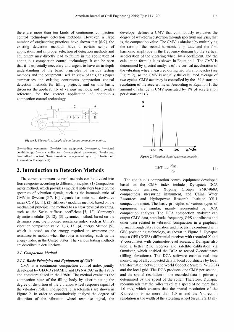
Figure 1. The basic principle of continuous compaction control.
(1—loading equipment; 2—detection equipment; 3—sensors; 4—signal
conditioning; 5—data collection; 6—analytical processing; 7—display;
8—feedback control; 9—information management system;; 11—Remote
Information Management)
2. Introduction to Detection Methods
The current continuous control methods can be divided into
four categories according to different principles: (1) Compaction
meter method, which provides empirical indicators based on the
spectrum of vibration signals, such as the harmonic ratio of
CMV in Sweden [5-7, 10], Japan's harmonic ratio derivative
index CCV [5, 11]; (2) stiffness / modulus method, based on the
mechanical principle, the method has a clear physical meaning,
such as the Swiss stiffness coefficient [5, 12], Germany's
dynamic modulus [5, 12]; (3) dynamics method, based on the
dynamics principle proposed resistance index, such as China's
vibration compaction value [1, 3, 13]; (4) energy Method [5],
which is based on the energy required to overcome the
resistance to motion when the roller is traveling, such as the
energy index in the United States. The various testing methods
are described in detail below.
2.1. Compaction Method
2.1.1. Basic Principles and Equipment of CMV
CMV is a continuous compaction control index jointly
developed by GEO-DYNAMIK and DYNAPAC in the 1970s
and commercialized in the 1980s. The method evaluates the
compaction state of the filling body by discriminating the
degree of distortion of the vibration wheel response signal of
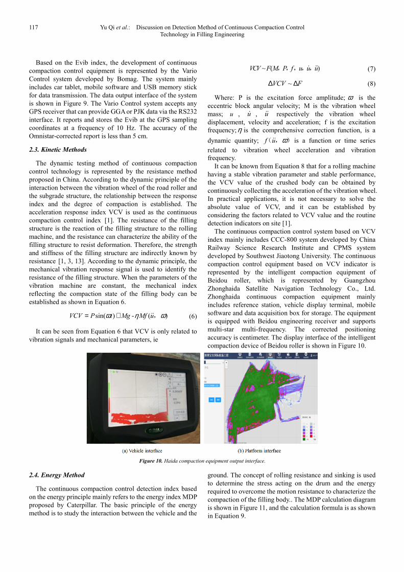
the vibratory roller. The spectral characteristics are shown in
Figure 2. In order to quantitatively analyze the degree of
distortion of the vibration wheel response signal, the
developer defines a CMV that continuously evaluates the
degree of waveform distortion through spectrum analysis, that
is, the compaction value. The CMV is obtained by multiplying
the ratio of the second harmonic amplitude and the first
harmonic amplitude in the frequency domain by the vertical
acceleration of the vibrating wheel by a coefficient, and the
calculation formula is as shown in Equation 1. The CMV is
determined by spectral analysis of the vertical acceleration of
the vibrating wheel measured during two vibration cycles (see
Figure 2), so the CMV is actually the calculated average of
two cycles. CMV accuracy is controlled by the 1% distortion
resolution of the accelerometer. According to Equation 1, the
amount of change in CMV generated by 1% of acceleration
per distortion is 3.
Figure 2. Vibration signal spectrum analysis.
2ACMV c
A
Ω
Ω= (1)
The continuous compaction control equipment developed
based on the CMV index includes Dynapac's DCA
compaction analyzer, Xugong Group's SMC-960A
compactness measuring instrument, and China Water
Resources and Hydropower Research Institute YS-1
compaction meter. The basic principles of various types of
equipment are similar, mainly represented by DCA
compaction analyzer. The DCA compaction analyzer can
output CMV, data, amplitude, frequency, GPS coordinates and
other data related to vibration compaction in a graphical
format through data calculation and processing combined with
GPS positioning technology, as shown in Figure 3. Dynapac
uses a GPS (DGPS) differential receiver with recorded X and
Y coordinates with centimeter-level accuracy. Dynapac also
used a better RTK receiver and satellite calibration via
Omnistar, which enabled the DCA to record Z-coordinates
(filling elevations). The DCA software enables real-time
monitoring of all compacted data in local coordinates by local
transformation between the World Geodetic System (WGS 84)
and the local grid. The DCA produces one CMV per second,
and the spatial resolution of the recorded data is primarily
determined by the speed of the roller. Therefore, Dynapac
recommends that the roller travel at a speed of no more than
1.0 m/s, which ensures that the spatial resolution of the
X-direction is no more than 1.0 m and the Y-direction
resolution is the width of the vibrating wheel (usually 2.13 m).

115 Yu Qi et al.: Discussion on Detection Method of Continuous Compaction Control
Technology in Filling Engineering
The data recorded by the DCA can be exported from the field
computer in a text file format for further analysis.
Figure 3. DCA type compaction analyzer output interface.
2.1.2. Basic Principles and Equipment of CCV
The CCV indicator is an extension of the CMV indicator,
and its basic principle is the same as CMV. The difference is
that CCV believes that the degree of compaction is not only
related to the 1.0 and 2.0 times harmonic amplitude, but also
to the 0.5, 1.5, 2.5 and 3 harmonic amplitudes. The
calculation principle of the CCV indicator is shown in
Equation 2.
1 3 4 5 6
1 2
100A A A A A
CCVA A
+ + + += × +
(2)
Where: A1-A6 represent the amplitudes of the 0.5, 1.0, 1.5,
2.0, 2.5, and 3.0 harmonics, respectively.
The continuous compaction control equipment developed
based on the CCV index is represented by a compaction
analyzer manufactured by Sakai. The basic principle of the
device is consistent with DCA, with real-time monitoring,
data recording and graphic output. The output interface of the
compaction analyzer produced by Sakai is shown in Figure 4.
Figure 4. Interface of the output of the compaction analyzer.
2.2. Stiffness / Modulus Method
2.2.1. Basic Principles and Equipment of Ks
Ks is a stiffness coefficient index proposed by Ammann
based on the principle of interaction between the vibrating
wheel and the rolling problem. The index uses a
two-degree-of-freedom model as shown in Figure 5.
Figure 5. Ks calculation model.
In the model shown in Figure 5, the soil is represented by
the Kelvin model, which is the excitation frequency of the
roller; md and mf are the masses of the vibrating wheel and the
frame respectively; zd and dzɺɺ are the displacement and
acceleration of the vibrating wheel, respectively; The
eccentric moment in the vibrating wheel. It can be seen from
Figure 5 that the contact force Fs of the vibrating wheel and
the crushing body is composed of four parts: the vibrating
wheel inertia, the frame inertia, the eccentric force and the
roller distributing weight. The inertia and eccentric force of
the drum are determined by measuring the vertical
acceleration and the eccentric position of the vibrating wheel,
while determining the displacement amplitude zd by
integrating the acceleration peak. When the frame inertia and
the roller distribution weight are ignored and the vertical
velocity component of the eccentric block is zero (i.e., the
eccentric block is at the lowest position), the calculation
equation as shown in Equation 3 can be obtained. Therefore,
Ks can be determined based on the measured acceleration and
phase lag of the vibrating wheel. Ks is actually the ratio of the
contact force to the maximum vertical displacement of the
vibrating wheel when the vertical velocity component of the
eccentric block is zero, as shown in Figure 6.
2 0 0 coss d
d
m eK m
z
ϕ = Ω +
( ) (3)
Where: φ is the phase lag between the eccentric force and
the vibration wheel displacement.
Figure 6. Ks calculation principle.

American Journal of Civil Engineering 2019; 7(4): 113-120 116
The main manufacturers of continuous compaction control
equipment based on the Ks index are Ammann and Case,
which are represented by Ammann's Ace Plus system. The
Ace Plus system calculates the stiffness factor of the
compacted body every vibration. The accuracy of the
measured data is as follows: dz∆ is not more than 0.001 mm;
ϕ∆ is not more than 0.5°; ∆Ω is not more than 0.31 rad/s.
The Ace Plus software (see Figure 7) combines the Ks data
with the X, Y, and Z coordinates acquired by the in-vehicle
GPS device with a coordinate accuracy of less than 10 cm.
When there is no reference signal (such as a base station), the
accuracy of the system is within a few meters. The Ace Plus
system calculates the metric for each vibration cycle and
combines the GPS data to report the average at 1 Hz. The
system software is installed in the tablet computer, and outputs
real-time vibration rolling parameters in a graphic format, as
shown in Figure 7a. All recorded data can be downloaded
from the onboard computer in a text file format via a USB
memory stick to compact the quality assessment. It should be
noted that Amman also provides a PC-based operating
platform for remote monitoring (see Figure 7b), which can
greatly improve project management efficiency.
Figure 7. Ace Plus software output interface.
2.2.2. Basic Principles and Equipment of Evib
Figure 8. Secant stiffness K solution.
Evib is a dynamic modulus index proposed by Bomag
based on vibration theory and elastic half-space theory. The
index uses the same two-degree-of-freedom model as the
stiffness coefficient index Ks. According to the mechanical
equilibrium condition of the calculation model, the contact
force Fs and the vertical displacement zd of the vibrating
wheel can be solved, and the yield-disturbance curve of the
compacted body is obtained by the combination of the data of
and, as shown in Figure 8. To determine Evib, the secant
stiffness is calculated from the compression portion of each Fs
and zd cycle, and the obtained secant stiffness is linked to the
dynamic modulus Evib. The dynamic modulus Evib can be
obtained by using the theoretical solution of the rigid cylinder
on the isotropic and uniform elastic half space proposed by
Lundberg [5], as shown in Equation 4.
22 1-1.8864 lns
d
F Lz
E L b
υπ×= × × +
×( )
( ) (4)
among them
216 1-s
Rb F
E L
υπ× ×= ×
× ×( )
(5)
Where: L is the vibration wheel width; R is the vibration
wheel radius; υ is the Poisson's ratio;E is the Young's
modulus.
Figure 9. Vario Control system output interface.
117 Yu Qi et al.: Discussion on Detection Method of Continuous Compaction Control
Technology in Filling Engineering
Based on the Evib index, the development of continuous
compaction control equipment is represented by the Vario
Control system developed by Bomag. The system mainly
includes car tablet, mobile software and USB memory stick
for data transmission. The data output interface of the system
is shown in Figure 9. The Vario Control system accepts any
GPS receiver that can provide GGA or PJK data via the RS232
interface. It reports and stores the Evib at the GPS sampling
coordinates at a frequency of 10 Hz. The accuracy of the
Omnistar-corrected report is less than 5 cm.
2.3. Kinetic Methods
The dynamic testing method of continuous compaction
control technology is represented by the resistance method
proposed in China. According to the dynamic principle of the
interaction between the vibration wheel of the road roller and
the subgrade structure, the relationship between the response
index and the degree of compaction is established. The
acceleration response index VCV is used as the continuous
compaction control index [1]. The resistance of the filling
structure is the reaction of the filling structure to the rolling
machine, and the resistance can characterize the ability of the
filling structure to resist deformation. Therefore, the strength
and stiffness of the filling structure are indirectly known by
resistance [1, 3, 13]. According to the dynamic principle, the
mechanical vibration response signal is used to identify the
resistance of the filling structure. When the parameters of the
vibration machine are constant, the mechanical index
reflecting the compaction state of the filling body can be
established as shown in Equation 6.
sin( ) - ( )VCV P t Mg Mf uω η ω= + ɺɺ, (6)
It can be seen from Equation 6 that VCV is only related to
vibration signals and mechanical parameters, ie
~ ( )VCV F M P f u u uɺ ɺɺ,,,,, (7)
~VCV F∆ ∆ (8)
Where: P is the excitation force amplitude; ω is the
eccentric block angular velocity; M is the vibration wheel
mass; u , uɺ , uɺɺ respectively the vibration wheel
displacement, velocity and acceleration; f is the excitation
frequency; η is the comprehensive correction function, is a
dynamic quantity; f u ωɺɺ( , ) is a function or time series
related to vibration wheel acceleration and vibration
frequency.
It can be known from Equation 8 that for a rolling machine
having a stable vibration parameter and stable performance,
the VCV value of the crushed body can be obtained by
continuously collecting the acceleration of the vibration wheel.
In practical applications, it is not necessary to solve the
absolute value of VCV, and it can be established by
considering the factors related to VCV value and the routine
detection indicators on site [1].
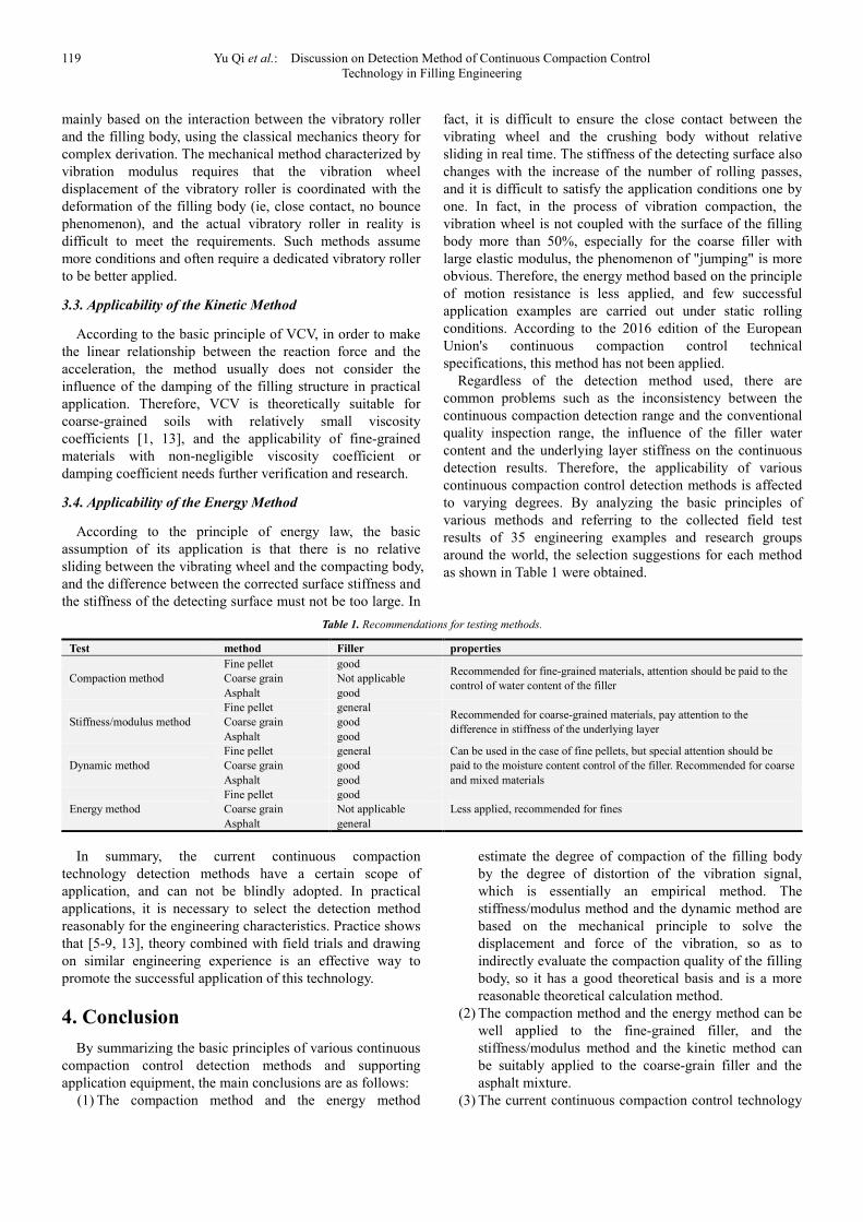
The continuous compaction control system based on VCV
index mainly includes CCC-800 system developed by China
Railway Science Research Institute and CPMS system
developed by Southwest Jiaotong University. The continuous
compaction control equipment based on VCV indicator is
represented by the intelligent compaction equipment of
Beidou roller, which is represented by Guangzhou
Zhonghaida Satellite Navigation Technology Co., Ltd.
Zhonghaida continuous compaction equipment mainly
includes reference station, vehicle display terminal, mobile
software and data acquisition box for storage. The equipment
is equipped with Beidou engineering receiver and supports
multi-star multi-frequency. The corrected positioning
accuracy is centimeter. The display interface of the intelligent
compaction device of Beidou roller is shown in Figure 10.
Figure 10. Haida compaction equipment output interface.
2.4. Energy Method
The continuous compaction control detection index based
on the energy principle mainly refers to the energy index MDP
proposed by Caterpillar. The basic principle of the energy
method is to study the interaction between the vehicle and the
ground. The concept of rolling resistance and sinking is used
to determine the stress acting on the drum and the energy
required to overcome the motion resistance to characterize the
compaction of the filling body.. The MDP calculation diagram
is shown in Figure 11, and the calculation formula is as shown
in Equation 9.

American Journal of Civil Engineering 2019; 7(4): 113-120 118
Figure 11. MDP calculation diagram.
sing
aMDP P WV mV b
gθ= − + − +( )( ) (9)
Where: gP is the total power required to move the
machine; W is the weight of the vibrating wheel; a is the
acceleration of the machine; g is the acceleration of gravity;
θ is the angle of inclination; V is the speed of the vibrating
wheel; m and b are the internal loss factor of the machine.
The second and third terms in Equation 9 represent the loss
energy associated with the slope and the machine power
associated with the internal machine loss, respectively.
Before using MDP, the calculation parameters in Equation 9
are determined by field calibration, and the value of MDP at
the calibration surface is set to zero, and the degree of
compaction is judged by comparing the size of the MDP.
Typically, a positive value for MDP indicates a relatively
looser degree of compaction than a calibrated surface, while
a negative value for MDP indicates a more compact degree
of compaction (ie, a smaller amount of drum sinking).
The continuous compaction control system based on the
MDP index is mainly represented by the Compaction Viewer
system developed by Caterpillar, as shown in Figure 12. The
Compaction Viewer system features data acquisition and
satellite positioning to display position and compaction
measurements in real time. The system uses GPS positioning
technology with a horizontal accuracy of ±10mm and a
vertical surface accuracy of ±20mm. The system can realize
visual monitoring of data on a PC.
Figure 12. Compaction Viewer system output interface.
3. Applicability Discussion
With the maturity of continuous compaction control
technology testing methods, countries and regions in the
world have successively formulated corresponding technical
standards and norms [14-16], and the technology has been
stipulated in the relevant project contract terms. The
continuous compaction technology has been well promoted
and applied in engineering practice. The Cologne-Rheinhe
high-speed railway Shinkansen project in Germany, the
asphalt pavement compaction project in the Raleigh area of
the United States, the Zoucheng section of the
Beijing-Shanghai high-speed railway in China, the Bottom
section of the Shanghai-Kunming high-speed passenger line,
the Minjiang section, and the Shiji railway passenger
transport The continuous subgrade compaction control
technology has been successfully applied to the project of the
base station of the East Plain Station and the TJ-10 section of
the Beijing-Shenyang Passenger Dedicated Line, and has
achieved good results. However, the Minnesota Expressway
Project in the United States, the Shenyang-Dandong
Expressway Project in China, the Harbin-Dalian Passenger
Dedicated Line Project, and the Lanxin Railway Project are
applied because there is no good correlation between the
continuous compaction test index and the compaction quality.
failure. It can be seen that there are both successful
experiences and many failed cases in practice. Analysis of the
reasons can be seen, although the current continuous
compaction control technology detection methods are more,
but there are certain scope of application. For a wide range of
engineering conditions, the ability to choose the right test
method will directly affect the successful application of
continuous compaction control technology. According to the
basic principle of each detection method, the applicability of
each method obtained by the analysis is as follows.
3.1. Applicability of the Compaction Method
The compaction gauge index evaluates the compaction
state based on the degree of distortion of the response signal,
and the main factor affecting the waveform distortion is the
first harmonic component [1, 5]. It is known from the
vibration theory that the strength of the interaction between
the road roller and the pressed structure determines the
spectral composition of the response signal, which is the root
cause of harmonic generation [5]. In fact, the contact of the
roller with the packing is uncoupled, and the vibrating wheel
is usually a nonlinear vibration. This nonlinear vibration
characteristic is more pronounced especially in the case of
coarse aggregates. Linear vibration generally only has a
simple frequency doubling component, and nonlinear
vibration is very complicated in the frequency domain.
Therefore, the compaction method is often only applicable to
the case of linear vibration, that is, rolling fine particle
working conditions.
3.2. Applicability of the Stiffness/Modulus Method
Based on the mechanical principle of Switzerland's
stiffness coefficient Ks, Germany's dynamic modulus Evib is
119 Yu Qi et al.: Discussion on Detection Method of Continuous Compaction Control
Technology in Filling Engineering
mainly based on the interaction between the vibratory roller
and the filling body, using the classical mechanics theory for
complex derivation. The mechanical method characterized by
vibration modulus requires that the vibration wheel
displacement of the vibratory roller is coordinated with the
deformation of the filling body (ie, close contact, no bounce
phenomenon), and the actual vibratory roller in reality is
difficult to meet the requirements. Such methods assume
more conditions and often require a dedicated vibratory roller
to be better applied.
3.3. Applicability of the Kinetic Method
According to the basic principle of VCV, in order to make
the linear relationship between the reaction force and the
acceleration, the method usually does not consider the
influence of the damping of the filling structure in practical
application. Therefore, VCV is theoretically suitable for
coarse-grained soils with relatively small viscosity
coefficients [1, 13], and the applicability of fine-grained
materials with non-negligible viscosity coefficient or
damping coefficient needs further verification and research.
3.4. Applicability of the Energy Method
According to the principle of energy law, the basic
assumption of its application is that there is no relative
sliding between the vibrating wheel and the compacting body,
and the difference between the corrected surface stiffness and
the stiffness of the detecting surface must not be too large. In
fact, it is difficult to ensure the close contact between the
vibrating wheel and the crushing body without relative
sliding in real time. The stiffness of the detecting surface also
changes with the increase of the number of rolling passes,
and it is difficult to satisfy the application conditions one by
one. In fact, in the process of vibration compaction, the
vibration wheel is not coupled with the surface of the filling
body more than 50%, especially for the coarse filler with
large elastic modulus, the phenomenon of "jumping" is more
obvious. Therefore, the energy method based on the principle
of motion resistance is less applied, and few successful
application examples are carried out under static rolling
conditions. According to the 2016 edition of the European
Union's continuous compaction control technical
specifications, this method has not been applied.
Regardless of the detection method used, there are
common problems such as the inconsistency between the
continuous compaction detection range and the conventional
quality inspection range, the influence of the filler water
content and the underlying layer stiffness on the continuous
detection results. Therefore, the applicability of various
continuous compaction control detection methods is affected
to varying degrees. By analyzing the basic principles of
various methods and referring to the collected field test
results of 35 engineering examples and research groups
around the world, the selection suggestions for each method
as shown in Table 1 were obtained.
Table 1. Recommendations for testing methods.
Test method Filler properties
Compaction method
Fine pellet good Recommended for fine-grained materials, attention should be paid to the
control of water content of the filler Coarse grain Not applicable
Asphalt good
Stiffness/modulus method
Fine pellet general Recommended for coarse-grained materials, pay attention to the
difference in stiffness of the underlying layer Coarse grain good
Asphalt good
Dynamic method
Fine pellet general Can be used in the case of fine pellets, but special attention should be
paid to the moisture content control of the filler. Recommended for coarse
and mixed materials
Coarse grain good
Asphalt good
Energy method
Fine pellet good
Less applied, recommended for fines Coarse grain Not applicable
Asphalt general
In summary, the current continuous compaction
technology detection methods have a certain scope of
application, and can not be blindly adopted. In practical
applications, it is necessary to select the detection method
reasonably for the engineering characteristics. Practice shows
that [5-9, 13], theory combined with field trials and drawing
on similar engineering experience is an effective way to
promote the successful application of this technology.
4. Conclusion
By summarizing the basic principles of various continuous
compaction control detection methods and supporting
application equipment, the main conclusions are as follows:
(1) The compaction method and the energy method
estimate the degree of compaction of the filling body
by the degree of distortion of the vibration signal,
which is essentially an empirical method. The
stiffness/modulus method and the dynamic method are
based on the mechanical principle to solve the
displacement and force of the vibration, so as to
indirectly evaluate the compaction quality of the filling
body, so it has a good theoretical basis and is a more
reasonable theoretical calculation method.
(2) The compaction method and the energy method can be
well applied to the fine-grained filler, and the
stiffness/modulus method and the kinetic method can
be suitably applied to the coarse-grain filler and the
asphalt mixture.
(3) The current continuous compaction control technology

American Journal of Civil Engineering 2019; 7(4): 113-120 120
detection methods generally have problems such as
poor applicability of fillers with different physical and
mechanical properties. For the specific engineering
conditions, comprehensive selection of appropriate
detection methods for continuous compaction control
can obtain satisfactory application results.
Acknowledgements
This paper is supported by the technical research topic
THZQ-033-2018 of Shenzhen Construction Industry
Department.
References
[1] Xu Guanghui. Dynamic principle and engineering application of continuous compaction control of roadbed [M], Beijing: Science Press, 2016.
[2] Tian Limin. Discussion on Compaction Standard and Acceptance Standard of Railway Subgrade of Passenger Dedicated Line [J]. Railway Standard Design, 2007 (11), pp. 1-4.
[3] Zhang Jialing, Xu Guanghui, Cai Ying. Study on quality inspection and control of continuous compaction roadbed [J]. Rock and Soil Mechanics, 2015, 36 (04), pp. 1141- 1146.
[4] Minnesota Department of Transportation. Mn/DOT Specification 2106 Pilot Specification for Embankment Grading Materials [S]. St Paul: Minnesota Department of Transportation Office of Research Services, 2007.
[5] Michael A. Mooney, Robert V. Rinehart, Norman W. Facas, et al. “Intelligent Soil Compaction Systems.” National Cooperative Highway Research Program Report 676 [R]. Washington, D. C.: Transportation Research Board, 2010.
[6] Fan Juan, Song Xiaodong, Tian Lifeng, Nie Zhihong. Analysis of influencing factors of continuous compaction quality inspection index CMV for high-speed railway subgrade [J]. Journal of Railway Science and Engineering, 2015, 12 (03), pp. 463-467.
[7] Anderegg, R., K. Kaufmann. “Intelligent Compaction with Vibratory Rollers.” Transportation Research Record 1868 [R]. Washington, D. C.: Transportation Research Board, 2004.
[8] Petersen, L. Continuous Compaction Control MnROAD Demonstration. Final report submitted to Mn/DOT, Report No. MN/RC-2005-07 [R]. St Paul: Minnesota Department of Transportation, 2005.
[9] XU Guang-hui, YAN Ze-hua. Study on the Limitation of Harmonic Ratio Index in the Method of Compaction in Continuous Compaction Control Technology [J]. Road Machinery & Construction Mechanization, 2015, 32 (08), pp. 39-42.
[10] Thumer H, Sandstrom A. Continuous compaction control, CCC [C]//European Workshop Compaction of Soils and Granular Materials, Presses Fonts et Chaussees, Paris, France. 2000, pp. 237-246.
[11] Nohse Y, Kitano M. Development of a new type of single drum vibratory roller [C]//Proc. 14th Intl. Conf. of the Intl. Soc. For Terrain-Vehicle Systems, Vicksburg, MS. 2002, pp. 1 -10.
[12] Krober W, Floss R, Wallrath W. Dynamic soil stiffness as quality criterion for soil compaction [J]. Geotechnics for roads, rail tracks, and earth structures, 2001, pp. 188-199.
[13] Zhang Jialing. Study on the uniformity of support stiffness of continuously compacted ballastless track subgrade structure [D]. Southwest Jiaotong University, 2014.
[14] China Railway Corporation. Q/CR 9210-2015 Technical Specification for Continuous Compaction Control of Railway Subgrade Filling Project [S]. Beijing: China Railway Publishing House, 2017.
[15] Ministry of Transport of the People's Republic of China. JT/T 1127-2017 Technical Conditions for Continuous Compaction Control System for Highway Subgrade Filling Project [S]. Beijing: China Communications Press, 2017.
[16] European Committee for Standardization. PD CEN/TS 17006:2016 Earthworks Continuous Compaction Con- trol [S]. London: BSI Standards Limited, 2017.