
Discussion Of Momentum Theory For Windmills
122
University of Massachuses Amherst ScholarWorks@UMass Amherst Wind Energy Center Reports UMass Wind Energy Center 1976 Discussion Of Momentum eory For Windmills Forrest S. Stoddard Follow this and additional works at: hps://scholarworks.umass.edu/windenergy_report is Article is brought to you for free and open access by the UMass Wind Energy Center at ScholarWorks@UMass Amherst. It has been accepted for inclusion in Wind Energy Center Reports by an authorized administrator of ScholarWorks@UMass Amherst. For more information, please contact [email protected]. Stoddard, Forrest S., "Discussion Of Momentum eory For Windmills" (1976). Wind Energy Center Reports. 20. Retrieved from hps://scholarworks.umass.edu/windenergy_report/20
Transcript of Discussion Of Momentum Theory For Windmills

University of Massachusetts AmherstScholarWorks@UMass Amherst
Wind Energy Center Reports UMass Wind Energy Center
1976
Discussion Of Momentum Theory For WindmillsForrest S. Stoddard
Follow this and additional works at: https://scholarworks.umass.edu/windenergy_report
This Article is brought to you for free and open access by the UMass Wind Energy Center at ScholarWorks@UMass Amherst. It has been accepted forinclusion in Wind Energy Center Reports by an authorized administrator of ScholarWorks@UMass Amherst. For more information, please [email protected].
Stoddard, Forrest S., "Discussion Of Momentum Theory For Windmills" (1976). Wind Energy Center Reports. 20.Retrieved from https://scholarworks.umass.edu/windenergy_report/20
UNNUZSrrV OF MASSACHUSETE/AMHUZST ENERGY ALTERNATIVES PROGRAM
UNIVERSITY OF MASSACHUSETTSIAMHERST
ENERGY ALTERNATIVES PROGRAM
DISCUSSION OF MOMENTUM THEORY FOR WINDMILLS
by
F o r r e s t S. Stoddard
U.Mass. Wind Furnace
Energy A1 t e r n a t i ves Program
U n i v e r s i t y o f Massachusetts
Amherst, Massachusetts 01002
TR/76/ 2
Appendix I V
DISCUSSION OF MOMEr4TUM THEORY FOR WINDMILLS
Molllenturn t heo ry has been e x t e n s i v e l y used t o p r e d i c t t h e r e l a t i v e p e r -
formance o f 1 i f t i n g p r o p e l l e r s a n d . r o t o r s . ' 2 y 3 y 4 ) The performance equa t ions
a r e a n a l y t i c a l l y and c o n c e p t u a l l y s imple; t h i s l eads t o q u i c k i d e a l p r e d i c t i o n s
and comparisons. Of ten a p h y s i c a l " f e e l i n g " o r unders tand ing o f t h e system can
be ga ined by e x e r c i s i n g t h i s s in ip le approach f i r s t , b e f o r e more complex b lade
element and s t r i p t h e o r i e s a r e used.
Th i s d i s c u s s i o n concerns t h e r a m i f i c a t i o n s and i n t e r p r e t a t i o n o f t h e
momentum theo ry express ions f o r a t h r u s t i n g w i n d m i l l i n t h e l i g h t o f observed
w i n d m i l l behav ior . I t shou ld be kep t i n mind t h a t t h e ( i d e a l i z e d ) a n a l y t i c a l
f o r m u l a t i o n depends on t h e f o l l o w i n g s t r i c t assumptions:
a ) d e f i n i t e s t r eam l i nes e x i s t i n t h e f l o w f i e l d ;
b ) no f r i c t i o n a l l osses a r e p resen t ;
c ) t h e induced v e l o c i t y impar ted t o t h e f r e e s t ream i s cons tan t ove r t h e
area o f t h e i d e a l i z e d r o t o r , o r a c t u a t o r .
The f o l l o w i n g wel l -known express ions a r e thus developed f o r t h e a c t u a t o r shown: ( 4 s )
T = t h r u s t = 2p A [Vo-v]v (1
Z P = power = T(Vo-V) = 211 A [ v 0 - v l v
I n non-dimensional form: t h r u s t T C = c o e f f i c i e n t = T
1 /2pAV0 2
power Cp = c o e f f i c i e n t = -
P 3
1 / 2 d V 0
and a x i a l a = i n t e r f e r e n c e = -- v
f a c t o r vo
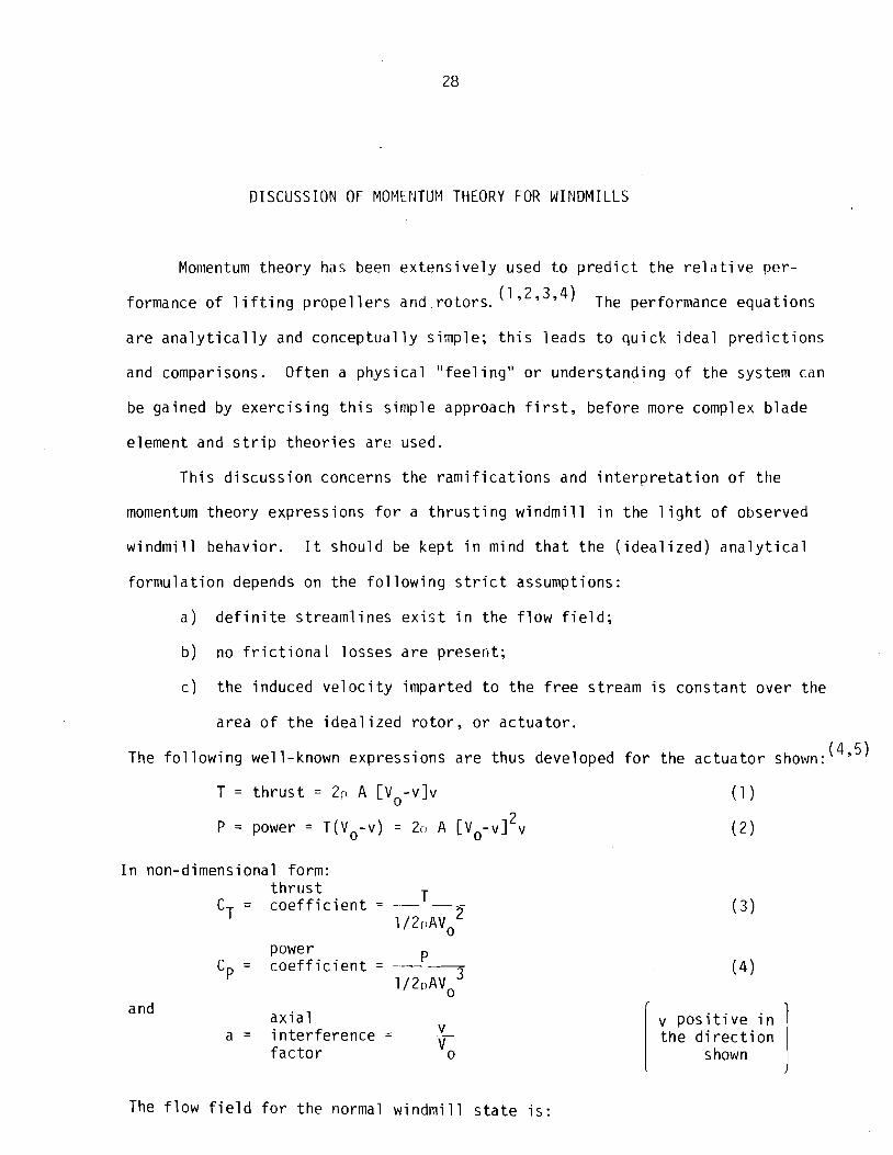
The f l ow f i e l d f o r t h e normal w i n d m i l l s t a t e i s :
I
v p o s i t i v e i n t h e d i r e c t i o n
shown I
where :
Actua tor !_ V o = f r e e stream v e l o c i t y
Disc V = f a r wake v e l o c i t y ru
v = induced v e l o c i t y
T = t h r u s t (down wind)
P = power (ou t of system)
FIGURE 1
Th is i s a l s o c a l l e d the w indmi l l brake s t a t e f o r r o t o r s s i nce t h e t h r u s t i s i n
the same d i r e c t i o n as the f r e e stream; thus, t h i s s t a t e represents a r o t o r i n
a u t o r o t a t i o n o r v e r t i c a l descent. I n w indmi l l terminology, as shown above,
t h r u s t c o e f f i c i e n t , CT, and power c o e f f i c i e n t , Cp, a r e p o s i t i v e , i n d i c a t i n g
t h r u s t ( o r drag) i n t h e downwind d i r e c t i o n and power o u t o f t h e system.
As shown by Wilson & Lissaman, Reference 1, t h e r e a r e two o the r impor tan t
f l ow s ta tes determined by the va lue o f induced v e l o c i t y , v, w r i t t e n non-
d in lens ional ly as a x i a l i n t e r f e r e n c e f a c t o r , a = v/Vo:
v = O
Normal Working S ta te (Windmi 11 Brake S ta te ) - - - - - - - .: <
0 - a - 0.5 . . . . . . - - . . - - - - . - . - - . - - - - - . Ci,, C o o s i t i vc T . . - - - - . - . . - - - - . . . - . - - - - - - -
Propel 1 e r S ta te
- a ; O
. - - - - - - -- - - - - - - - . . . - - - - - - - - -. Cp, CT negat ive
- - - - . . - - - -. - - - . . . . - - . . - . . . . -
Zero S l i p Case
a = O - -. -. - - - - -. -
C P =C -I- = O - - -- - - - - - - - - - -. - - - - - - -- - -
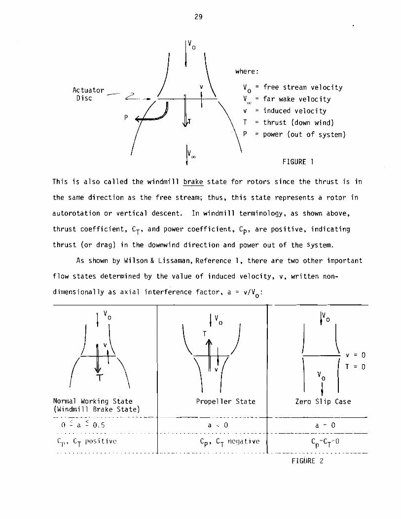
For a = 1/2, t he developed wake v e l o c i t y i s :
f a r V = wake = Vo( l - 2a) = 0 " v e l o c i t y
Th i s c o n d i t i o n represen ts a p o i n t a t which s t reaml ines no l onge r e x i s t .
Hence, t h e momentum theo ry assumption has been v i o l a t e d , and t h i s s t a t e cannot
e x i s t as a momentum theo ry s o l u t i o n .
W r i t i n g CT and Cp i n terms o f a:
Wi lson & Lissamanget t h e f o l l o w i n g p l o t (Reference 1 ) :
C~
I I
- 1.5
a = v/V 0
Momentum theo ry does n o t work
I I I I FIGURE 3

For a -1.0, the f a r wake v e l o c i t y , V .,, , i s s t i l l n o t de f ined by 11ionientu111 theory;
b u t t h i s s t a t e can a l s o be seen t o be the p r o p e l l e r a c t i n g a s a brake. That i s ,
power i s being added t o the f l o w t o c rea te h igh CT, o r h i g h t h r u s t downwind.
This would be the case o f reve rs ing p r o p e l l e r t h r u s t on land ing .
These f l o w s ta tes represent a se r ies o f gradual changes which occur on
t h e r o t o r as induced v e l o c i t y i s changed un i fo rm ly . Unfor tunate ly , because a >
d e f i n i t e s l i ps t ream does n o t e x i s t f o r a -112, momentum theory cannot be used t o
p r e d i c t t he r o t o r performance i n t h i s region. However, f rom h e l i c o p t e r auto-
r o t a t i v e data, emp i r i ca l curves have been drawn, and the f l o w s ta tes have been
documented. ( 2 9 6 9 7 ) Expanding t h e curve from the preceding page, the r o t o r
behavior can be described i n more d e t a i 1 :
Windmil 1 Brake Sta te
Zero S l i p
I Propel l e r S ta te Turbulent Wake S ta te
FIGURE 4

The e l l ~ p i r i c a l s t a t e boundaries a r e found f r om t y p i c a l h e l i c o p t e r descent
( a u t o r o t a t i v e ) perforl l lance d a t a p l o t t e d as f o l lows. The absc issa i s non-dimen-
s i o n a l r a t e o f c l imb , To, and t h e o r d i n a t e i s non-dimensional induced v e l o c i t y . - v, as d e f i n e d below:
w i t h - v - o v = n 7 7 J r ; = J T / L ~ A
[Note: Here t he s i g n o f t h e f r e e stream v e l o c i t y , Vo, i s o p p o s i t e t o t h a t used
f o r wi ndmi 11 t heo ry ]
- v
Data f rom I
[Momentum \l;i \ , , \ + - 5 theory does
fnot -- - - - - - -
Vortex Ring S t a t e ( Ro to r o r P r o p e l l e r S t a t e , . - .
FIGURE 5
, I Windmi l l Brake S t a t e I 1 I 1
( h e l i c o p t e r ascending)
I I 1
- 3 I I I
J - ~ L - 1 0 1 2 3 -
Turbu len t Wake S t a t e vo
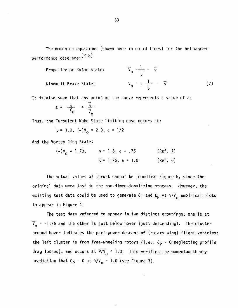
The niomentuni equat ions (shown here i n so l i d 1 i nes ) f o r t h e he1 i c o p t e r
perfor~i iance case are: (2'8)
P r o p e l l e r o r Rotor S ta te
CJindmi 11 Brake State:
I t i s a l s o seen t h a t any p o i n t on the curve represents a value o f a:
Thus, t h e Turbu len t Wake S ta te l i m i t i n g case occurs a t : - v = 1.0, ( - ) v o = 2 , a = 1/2
And t h e Vortex Ring S ta te : -.
( - ) \ 1.73, v = 1.3, a = -75 (Ref. 7 ) - V = 1.75, a - 1.0 (Ref. 6)
The ac tua l values of t h r u s t cannot be foundfroni F igu re 5, s ince the
o r i g i n a l data were l o s t i n t he non-dimensional iz ing process. However, t h e
e x i s t i n g t e s t data cou ld be used t o generate CT and Cp vs v/Vo emp i r i ca l p l o t s
t o appear i n F igu re 4.
The t e s t data r e f e r r e d t o appear i n two d i s t i n c t groupings; one i s a t - Vo = -1.75 and the o the r i s j u s t below hover ( j u s t descending). The c l u s t e r
around hover i n d i c a t e s the part-power descent o f ( r o t a r y wing) f l i g h t v e h i c l es ;
t h e l e f t c l u s t e r i s from free-wheel ing r o t o r s ( i . . , Cp = 0 neg lec t i ng p r o f i l e - -
drag losses) , and occurs a t v/Vo 2 1.0. This v e r i f i e s the momentum theory
p r e d i c t i o n t h a t Cp = 0 a t v/Vo = 1.0 (see F igu re 3 ) .

I n t he Tu rbu len t Wake S ta te , t h e s l i p s t r e a m expansion i s ve ry l a r g e , and
cons ide rab le tu rbu lence and r e c i r c u l a t i o n e x i s t (Reference 2 ) . I n f a c t , t he
r o t o r ac t s as a l a r g e d i s c pe rpend i cu la r t o t h e f l ow . Thus, t h e t h r u s t
c o e f f i c i e n t i s synonymous w i t h t h e drag c o e f f i c i e n t o f a s o l i d d i s c :
C,, 1.5 - 2.0. As a r e s u l t we would expect t h e CT t o go up s h a r p l y as
a = v/V (synonymous w i t h p o r o s i t y of t h e d i s c ) inc reases . Hence, we would 0
expec t h i ghe r va lues o f CT than those p r e d i c t e d by momentum theory .
The Vor tex Ring S t a t e boundary i s n o t w e l l es tab l i shed , b u t has been
observed f o r a number of d i f f e r e n t NACA r o t o r s (see Reference 6) and e a r l i e r
t e s t s (see Reference 7 ) . Th is boundary a l s o marks t h e change f rom p o s i t i v e
t o nega t i ve power; t h a t i s , t h e v o r t e x r i n g s t a t e represen ts h e l i c o p t e r r o t o r s
i n powered a u t o r o t a t i o n ( f o r which s i g n i f i c a n t t e s t data e x i s t ) as w e l l as
r e v e r s e t h r u s t i n g p rope l 1 e r s ( t h e same f l o w f i e l d ) . Momentum theo ry cannot be
b e l i e v e d i n t h e range, 1/2 < a < 1.0, b u t t h e power equa t i on (Equat ion 5 ) does
p r e d i c t t h e change i n Cp (see F igu re 3 ) .

References
1. Wilson &Lissaman "Applied Aerodynamics of Wind Power Machines," Oregon State University, July 1974.
2. Gessow & Myers, Aerodynamics of the Helicopter, Frederick Ungar Publishing, 1952.
3. Prandtl & Tietjens, Applied Hydro & Aeromechanics, Dover Publications, 1934.
4. Glauert, Elements of Aerofoil & Airscrew Theory, Cambridge University Press, 1959.
5. Glauert, "Windmills and Fans," Aerodynamic Theory, Vol IV, Durand, ed., Dover Pub1 ications, 1963, pp. 324-332.
6. Gessow, "Flight Investigation of Effects of Rotor Blade Twist on Helicopter Performance in the High Speed and Vertical-Autorotative Decsent Conditions," NACA TN 1666, 1948.
7. Lock, Bateman, Townend, "An Extension of the Vortex Theory of Airscrews with Applications to Airscrews of Small Pitch and Includivg Experimental Results," British Aeronautical Research Comm. Reports & Memoranda, No. 1014, 1924.
8. Ham, "V/STOL Vehicle Aerodynamics and Dynamics," Course 16.50 class notes, MIT, 1963.

UNIVERSITY OF MASSACHUSETTS/AMHERST ENERGY ALTERNATIVES PROGRAM
UNIVERSITY OF MASSACHUSETTS/AMHERST
ENERGY ALTERNATIVES PROGRAM
AN APPROACH TO PRELIMINARY SYSTEMS OPTIMIZATION
OF THE NEW ENGLAND WIND FURNACE
F o r r e s t S. S t o d d a r d
U.Mass. Wind F u r n a c e
E n e r g y A l t e r n a t i v e s P rog ram
U n i v e r s i t y o f M a s s a c h u s e t t s
Amhers t , M a s s a c h u s e t t s 01002
TR/76 /3 A p p e n d i x V

AN APPROACH TO-,PR_F-~_T_M!~lA~Yv _S_Y;T_E_M_S- _O_PTJfl,ZA_TT_ION- _OJ_ T! 1.r- r\rLw. JNGLAND. !dI gn. 11 l?N?c r --
1. Genera 1 Approach
The Wind Furnace system i s represented i n F igu re 1. The diagram
i l l u s t r a t e s t h e t h r e e independent c o n t r o l v a r i a b l e s : p i t c h ( ) f i e l d
e x c i t a t i o n (PeXc), and l o a d r e s i s t a n c e (RL). That is, f o r each s e t o f
i n p u t c o n d i t i o n s (Vo,B,,Pex, , R ) t h e r e w i l l be an ou tpu t energy, 1 ; ~ ~ .
The o p t i m i z a t i o n t ask c o n s i s t s o f f i n d i n g t h e r i g h t combinat ions of these
v a r i a b l e s which y i e l d t h e h ighes t ou tpu t f o r g i ven wind speed, Vo. La te r ,
t h e a n a l y s i s can be r e f i n e d t o g i v e dynamic and s t a b i l i t y improvements
g i ven V o ( t ) ( s u b j e c t t o t h e q u a s i - s t a t i c assumptions used i n d e r i v i n g
t h e a n a l y t i c a l models f o r t h e p r o p e l l e r and gene ra to r ) . T rans ien t behavior
o f t h e system may be at tempted f o r c e r t a i n e q u i l i b r i u m cases, as i s done
w i t h s t a b i l i t y d e r i v a t i v e s f o r f l i g h t systems.
Pre l im inary , o r " s t a t i c , " systems o p t i m i z a t i o n uses a n a l y t i c and/or
semi-empir ica l performance c h a r a c t e r i s t i c s of t h e two subsystems, and
s imp ly matches ope ra t i ng p o i n t s t o determine e q u i l i b r i u m c o n d i t i o n s .
Parametr ic torque-speed p l o t s w i l l be used i n t h i s ana lys is ; hence t h e
i n t e r p r e t a t i o n of "matching t h e c h a r a c t e r i s t i c s , " i s t o equate t h e ou tpu t
to rque o f t h e mechanical ( w i n d m i l l ) shaft , t o t h e i n p u t t o rque o f t h e generator .
The parametr ic performance of t h e genera to r has been measured i n
l a b o r a t o r y t e ~ t s ( ~ ) ( ~ i g u r e 2 ) . For each p o i n t on t h i s p l o t an ou tpu t load
2 c u r r e n t , Icy w i l l determine t h e o u t p u t power, I o R L - Work i s con t i nu ing , t o
develop an a n a l y t i c a l model f o r t h e genera to r and f o r o t h e r types of
generators . I t i s understood t h a t l a b o r a t o r y t e s t s a re impor tan t f o r t he
comprehension and v e r i f i c a t i o n of t h e genera l a n a l y t i c a l theory .

Heat Energy
T genera t o r
FIGURE 1
' exc i ta t ion
N - RPM
FIGURE 2

Uo changing 0~ Input Torque
(Windmill)
Torque
N - RPM o f wi ndmi 1 1
FIGURE 3
R PM
FIGURE 4
input (windmill)
R PM
FIGURE 5
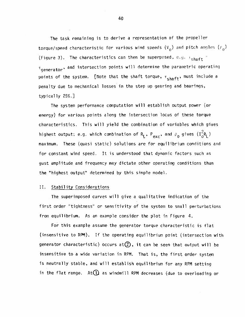
The task remain ing i s t o d e r i v e a r e p r e s e n t a t i o n o f t he p r o p e l l e r
torque/speed c h a r a c t e r i s t i c f o r va r i ous wind speeds (v,) and p i t c h al lq les (I:,)
( F i g u r e 3 ) . The c h a r a c t e r i s t i c s can then be superposed, e.Lj. l s h a f t
T and i n t e r s e c t i o n p o i n t s w i l l determine t h e paramet r i c ope ra t i ng genera to r '
p o i n t s o f t he system. [Aote t h a t t h e s h a f t torque, T ~ ~ ~ ~ ~ , must i n c l u d e a
p e n a l t y due t o mechanical losses i n t h e s tep up gea r i ng and bear ings,
t y p i c a l l y 25%.]
The system performance computat ion w i l l e s t a b l i s h ou tpu t power ( o r
energy) f o r va r i ous p o i n t s a long t h e i n t e r s e c t i o n locus o f these to rque
c h a r a c t e r i s t i c s . T h i s w i l l y i e l d t h e combinat ion o f v a r i a b l e s which g i ves
h ighes t output ; e.g. which combinat ion o f RL, Pexc, 2
and fro g i ves (I,RL)
maximum. These (quas i s t a t i c ) s o l u t i o n s a re f o r e q u i l i b r i u m c o n d i t i o n s and
f o r cons tan t wind speed. I t i s understood t h a t dynamic f a c t o r s such as
gus t ampl i tude and frequency may d i c t a t e o the r ope ra t i ng cond i t i ons than
t h e "h ighes t ou tpu t " determined by t h i s s i l ~ ~ p l e model.
I I. S t a b i l i t y Considerat ions
The superimposed curves w i l l g i v e a q u a l i t a t i v e i n d i c a t i o n of t he
f i r s t o rder " t i g h t n e s s " o r s e n s i t i v i t y of t h e system t o smal l p e r t u r b a t i o n s
from e q u i l i b r i u m . As an example cons ider the p l o t i n F igu re 4.
For t h i s example assume t h e generator to rque c h a r a c t e r i s t i c i s f l a t
( i n s e n s i t i v e t o RW) . If the ope ra t i ng equ i 1 i brium p o i n t ( i n t e r s e c t i o n w i t h
generator c h a r a c t e r i s t i c ) occurs a t @ , i t can be seen t h a t ou tpu t w i 11 be
i n s e n s i t i v e t o a wide v a r i a t i o n i n RPM. That i s , t he f i r s t o rde r system
i s n e u t r a l l y s tab le , and w i l l e s t a b l i s h e q u i l i b r i u m f o r any RPM s e t t i n g
i n t h e f l a t range. A ~ Q as w i n d m i l l RPM decreases (due t o over load ing o r

gus t s ) t h e genera to r c h a r a c t e r i s t i c must be changed t o keep from s t a l l i n g
t h e system; l i k e w i s e , an inc rease i n i n p u t RPM w i l l cause t h e system t o
d i ve rge . Th i s c o n d i t i o n i s s t a t i c a l l y uns tab le . I n reg ion@ t h e system
i s s t a t i c a l l y s t ab le , s i nce a p e r t u r b a t i o n i n w i n d m i l l RPM w i l l cause an
oppos i t e change i n excess torque. The s lope of t h e c h a r a c t e r i s t i c i s
analogous t o s p r i n g r a t e , and i f o t h e r dynamic (h i ghe r o r d e r ) i n f l u e n c e s
a r e impor tan t , t h e s l ope w i l l be analogous t o t h e n a t u r a l f requency o f
v i b r a t i o n i n t h a t mode.
Now reexamine t h e assumption of f l a t genera to r torque; cons ide r F igu re
5. We have es tab l i shed t h a t c o n d i t i o n a i s s tab le ; i f i n p u t RPM decreases
t h e t o rque increment A T i s p o s i t i v e , and reacce le ra tes t h e system t o
e q u i l i b r i u m . I t i s e v i d e n t t h a t t h i s t o rque increment a l s o depends on
t he s lope of t h e genera to r c h a r a c t e r i s t i c : v i z . , f o r l i n e a t h e A T i s
l a r g e r and t h e system t h a t much " t i g h t e r " ; and f o r l i n e @ t h e A T has
decreased t o a smal l r e s t o r a t i v e q u a n t i t y . Thus, f o r l i n e 4, t h e system
i s s t a t i c a l l y unstab le ; i . e . t h e s lope o f t h e o u t p u t c h a r a c t e r i s t i c i s
l a r g e r than t h e s lope of t h e i n p u t c h a r a c t e r i s t i c .
111. Approach t o P r o p e l l e r S o l u t i o n
The approach f o r s o l u t i o n s of t h e p r o p e l l e r problem i s t o develop power-
speed and torque-speed c h a r a c t e r i s t i c s us ing nondimensional q u a n t i t i e s t o rque
and power c o e f f i c i e n t s and t i p speed r a t i o ; t h i s e l i m i n a t e s t h e dependence
on V o o r on RPM. The nondimensional p l o t can then be used t o develop any
des i r ed c r o s s - p l o t a t any d e s i r e d V o t o be used i n match ing t h e system.
One o f t h e e x i s t i n g computat ional r e s u l t s i s a p l o t of t h e power
c o e f f i c i e n t maxima, f o r v a r i o u s t i p speed r a t i o s , f o r t h e machine, see F i g u r e
6. T h i s curve represen ts t h e locus of a l l maxima of i n d i v i d u a l C curves P


f o r va r i ous va lues o f ro, as shown. For a f i x e d p i t c h aachine, t h e
performance c h a r a c t e r i s t i c would be as shown on t h e do t ted l i n e . For
synchronous (cons tan t speed) w i ndm i l l systems, the power c o a f f i c i e n t v a r i a t i o n
w i t h i nc reas ing wind speed i s determined f rom t h i s p l o t ( 2 ) .
The torque can be der ived f rom t h i s curve us ing t h e f o l l o w i n g approach.
The d e f i n i t i o n s are:
power - P - -- Cp = c o e f f i c i e n t 1 3
?PA",
p = d e n s i t y o f a i r @ sea l e v e l
A = p r o p e l l e r d i s c area
V o = wind speed
to rque .r 'T = c o e f f i c i e n t = 1 2
p A V o R wi th :
t i p speed - szR - - = r a t i o
0
n = r o t a t i o n a l speed
R = r a d i u s o f p r o p e l l e r
A1 so:
Thus the to rque c o e f f i c i e n t can be found d i r e c t l y f rom the C s imu la t i on P
r e s u l t s . The C T dependence on p i t c h w i l l l i k e w i s e be shown (F igu re 7 ) . When t h i s r e l a t i o n s h i p i s found, a map of p o i n t s (paramet r ic p l o t )
w i l l be ca l cu la ted f o r each wind speed o f i n t e r e s t , and ac tua l torque vs. RPM
curves can be generated (see F igu re 8 ) . There w i l l be reg ions on these
p l o t s which w i l l i n d i c a t e aerodynamic non- - l inear phenomena, and w i l l p robably
n o t be impor tan t e q u i l i b r i u m cond i t i ons :
s t a l l - occurs where angle of a t t a c k i s h igher than the maximum a ) -
value f o r ma in ta in ing s t reaml ines f o r the p a r t i c u l a r a i r f o i l o f

T = t o rque
1 ocu s of 111ax inlulr~ va 1 ues
/
/
F I G U R E 7
N RPM
F I G U R E 8

i n t e r e s t ; performance i s sharp ly degraded.
b) reverse f l o w - where l o c a l v e l o c i t y over blade i s from the
t r a i l i n g edge forward; thus w i l l p robably n o t occl;r except i n
smal l p o r t i o n s o f the b lade and f o r unusual cond i t i ons ; t h i s
c o n d i t i o n w i l l n o t show up except as a r a p i d decrease i n C w i t h 1 1 . P
c ) nega t i ve l i f t -- - the w indmi l l a c t s as a p r o p e l l e r as angles o f
a t t a c k , 1 i f t , and torque, become negat ive.
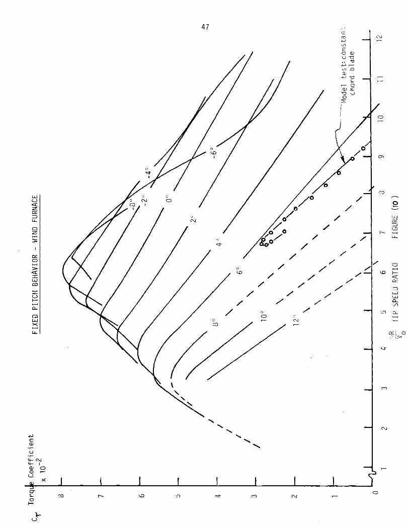
I V . Resu l ts o f P r o p e l l e r S imu la t i on
The computat ional r e s u l t s o f t he performance ( s t r i p ) t heo ry a re shown
i n F igures 9 and 10. I n F igu re 9 can be seen t h e cons tan t p i t c h curves
used t o generate t h e locus o f C maxima shown i n F igure 6 . As p i t c h ang le P
(B,) i s decreased (e.g. angle of a t t a c k o f blade elements increased as shown
i n the i n s e t ) , t h e r o t o r i s loaded more and more. As the angle changes,
t h e t i p speed r a t i o f o r h ighes t power increases t o about 9 (B eo = -2")
and then decreases t o t h e design t i p speed r a t i o o f 7. The decrease i n
power w i t h increased p i t c h angle represents t h e c o n t r o l ph i losophy advanced
for ' "ra ted (26.1 MPH); t h a t i s , sha f t speed i s kept cons tan t and C P
decreases w i t h i nc reas ing f ree stream v e l o c i t y . Th is phi losophy i s a l so
discussed by utter,") ~ o l d i n g , ( ' ) ~ o h r b a c k , ' ~ ) and ~ e u t s c h , ' ~ ) among o thers .
A s i m i l a r curve i n terms of power (wa t t s ) vs. RPM, i s shown i 1 1 F igure 11.
These r e s u l t s were obta ined from wind tunnel t e s t s of a f i x e d p i t c h , constant
chord b lade (Reference 7 ) . The corresponding power c o e f f i c i e n t c h a r a c t e r i s t i c
i s inc luded i n F igure 9 .
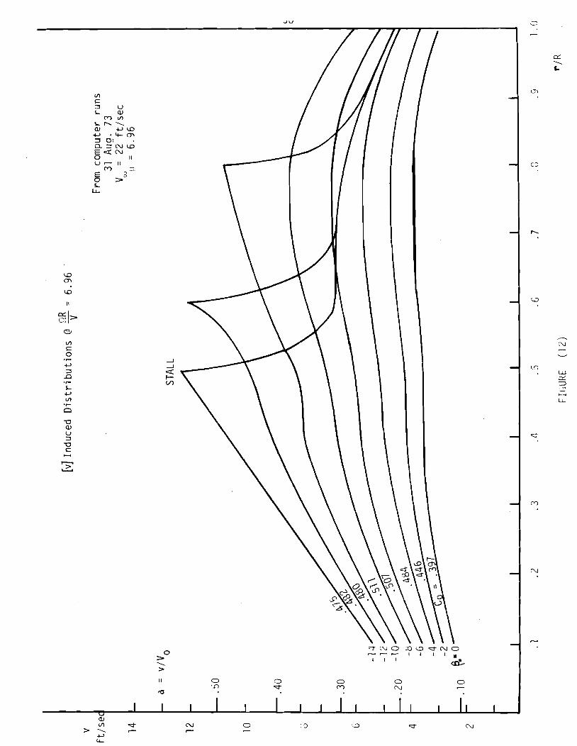
I n F igu re 9, as p i t c h angle i s decreased, t h e power c h a r a c t e r i s t i c
becomes more and more s e n s i t i v e . The l e f t margin of each c l l rve i s a s t a l l
boundary; a phenomenon which occurs f i r s t a t t he t i p o f t h e blade, s ince t h e
NEWF design i s c l ose t o optirnum t w i s t and taper . The induced v e l o c i t y


0 30i) 40U 500 GOO 7 00 800 900 1000 1100 R P I,.I FTCIIRF ( 1 1 \

(downwash) d i s t r i b u t i o n a long the b lade i s c h a r a c t e r i s t i c o f optimum
designs (see F igu re 12). Untwisted, and cons tan t chord, blades show a much
l e s s s e n s i t i v e s t a l l t h a t s t a r t s a t t he r o o t a t much srlialler p i t c h angles (5,6).
thus, t h e power c h a r a c t e r i s t i c o f an o f f - d e s i q n b lade w i l l , be f l a t t e r and
have smal le r C than t h e NEWF b lade (see F igures 9 and 11) . T h i s p o i n t s P
o u t t h e need f o r thorough s t a b i l i t y a n a l y s i s o f the optimum momentum
exchanger system p h i 1 osophy adopted f o r t h e NEWF design.
Also, from F igu re 9, t h e power c h a r a c t e r i s t i c i s seen t o become
h ighe r o rder as s t a l l i s approached; t h a t i s , a t p i t c h angles l e s s than
0°, t he drop i n power w i t h i nc reas ing t i p speed r a t i o ( o r RPCl f o r cons tan t
V ) i s much more severe. Th is i s a l s o be l i eved t o be a f u n c t i o n o f 0
b lade design, cha rac te r i zed by increased drag and h i g h l y t w i s t e d sec t i ons
becoming negat ive l i f t .
I n F igu re l o i s p l o t t e d t he corresponding to rque c h a r a c t e r i s t i c ,
discussed e a r l i e r . The non - l i nea r behavior a t p i t c h angles l e s s than 0"
i s a l s o seen. But t h e s t r i k i n g c h a r a c t e r i s t i c i s t h e l i n e a r i t y o f the
to rque curves over t h e u n s t a l l e d reg ion . Th i s represents system s t a t i c
s t a b i l i t y f o r each cons tan t p i t c h s e t t i n q ( i n t he 1 i n e a r range) .
Near maximum torque, t h e curves a r e ve ry peaky, and may c o n s t i t u t e a
ca tas t roph i c s t a l l f o r smal l RPM pe r tu rba t i ons . T y p i c a l l y , these RPM
v a r i a t i o n s w i l l be caused by gusts; an inc rease i n wind speed momentar i ly
decreasing t i p speed r a t i o , and v ice-versa . However, when 1~ i s decreased f a r
enough t o push t h e p r o p e l l e r i n t o s t a l l , t h e r e i s a l s o a ba lanc ing e f f e c t
caused by t h e inc rease i n to rque a v a i l a b l ~ i n t h e f r e e stream (e.g. due t o
increased wind v e l o c i t y ) . Therefore, t he dynamic behavior i s impor tan t , and
must be considered f o r a r e a l i s t i c s t a b i l i t y and ~ o n t r o l s o l u t i o n .

More a n a l y t i c a l and exper imenta l da ta a r e needed t o e s t a b l i s h thc!
slopes o f t h e to rque curves a t t h e absc issa i n t e r s e c t i o n (e.g. r o t o r un loaded) .
Th i s i s t he c o n d i t i o n which would be reached i n the event o f a s h a f t o r
genera to r f a i l u r e . The wind generator w i l l speed up t o the p o i n t a t which
sha f t to rque i n p u t j u s t balances f r i c t i o n torque, and c l a s s i c a l " w i n d m i l l i n g "
i s achieved. ( 7 ) [Th i s i s n o t t he same as fea ther ing , which i s represented
by t h e o r i g i n , o r zero RPM.]
V. Rotor Flow Sta tes
The va r i ous r o t o r f l o w s t a t e s can be i d e n t i f i e d on t h i s c h a r a c t e r i s t i c . (595)
The Zero S l i p Case i s represented by CT = 0 j u s t discussed; and t h e P r o p e l l e r
S ta te i s below t h e abscissa, where CT i s nega t i ve (power goes i n t o t he system).
As t h e cons tan t p i t c h p r o p e l l e r i s loaded more and more, t he o u t p u t power (and
t h r u s t ) increases t o t h e p o i n t where ( t o r q u e x RPM) = power i s a maximum
( to rque a lone i s n o t a maximum). T h i s p o i n t occurs, accord ing t o momentum
theory, where t h e average i n f l o w i s 1/3; and t h e i d e a l C = .5926.(2) I f P
l oad ing i s increased beyond t h i s , t h e i n f l o w inc reases on t h e b lade u n t i l t h e
a i r f o i l s t a l l s ; power f a l l s o f f and t h r u s t ( n o t shown) increases, as v e r i f i e d
by he1 i c o p t e r a u t o r o t a t i v e t e s t s . ( 6 ) Th i s i s c a l l e d t he Turbu len t Wake State,
and i s cha rac te r i zed by t he absence of s t reaml ines , severe b u f f e t i n g , and t h e
qu i ck f a l l - o f f i n developed power. The task o f t he c o n t r o l system w i 11 be t o
p revent ent rance i n t o t h i s ope ra t i ng s ta te , even f o r t r a n s i e n t cond i t i ons . I t
should be understood t h a t f o r h i g h va lues of fro (e.g. 12O) t he angles o f
a t t a c k a r e smal l t o beg in w i t h , and i t i s u n l i k e l y t h a t a s i g n i f i c a n t p o r t i o n
o f t he ( h i g h l y t w i s t e d ) b lade cou ld ever be s t a l l e d . And t h e b lade may never
r e a l l y e n t e r Tu rbu len t Wake Sta te . Hence a p o s i t i v e ou tpu t to rque cou ld be
expected f o r ext remely low RPM ( o r u ) . However, our d i scuss ion w i l l focus

on p i t c h angles c l o s e r t o t h e t o rque and power peaks, where most r unn inq
i s done.
I t i s i n s t r u c t i v e t o examine t h e b l ade element diaqrams f o r these
f l o w s t a t e s . From Wi lson and Lissman, Reference 5, F i g u r e 13 i s
reproduced.
From examina t ion o f F i g u r e '1 3, t h e "average" b lade element s i t u a t i o n
can be descr ibed f o r r e g i o n s o f t h e power c h a r a c t e r i s t i c , F i g u r e 9 , as
d iscussed. I n t h e T u r b u l e n t Wake S t a t e , power decreases r a p i d l y as most
o f t h e b lade i s s t a l l e d , and t h r u s t i nc reases r a p i d l y . I f t h e b l ade i s a l lowed
t o r each s t a l l e d e q u i l i b r i u m , t h e r e s t i n g p o i n t i s aga in t h e ze ro t o r q u e
absc issa . Tha t i s , a f i x e d p i t c h w i n d m i l l can be d r i v e n i n t o t h e s t a l l e d ,
o r T u r b u l e n t Wake S t a t e , and t h i s w i l l cause t h e p r o p e l l e r - g e n e r a t o r
system t o become s t a t i c a l l y uns tab le ; a s l i g h t - i n c r e a s e i n gene ra to r t o rque
( o r l oad ) w i 11 cause a r a p i d decrease i n p r o p e l l e r 9PM and t h e t o rque w i l l
d rop t o zero. Most gene ra to r s have " r e s i d u a l " t o r q u e when unloaded a t l ow
RPM. The cons tan t f i e l d i n a p e r m a n e n t magnet genera to r , and t h e r e s i d u a l
magnetism i n s e p a r a t e l y e x c i t e d f i e l d machines, w i l l be a l a r g e r e s i d u a l
to rque . The s t a l l e d e q u i l i b r i u m , t h e r , w i l l be t h e p o i n t a t which t h e
T u r b u l e n t Wake S t a t e sha f t t o rque ( s l i g h t l y p o s i t i v e ) w i 11 j u s t be enough
t o balance t h e gene ra to r " r e s i d u a l " t o rque . 1 f ' t h e r e s i d u a l magnetism o r
permanent f i e l d i s t o o h i g h even f o r v e r y low RPM's, t h e w i n d m i l l can
a c t u a l l y come t o r e s t . I n p r a c t i c e , a machine such as t h i s i s seldom seen
because i t would n o t be s e l f - s t a r t i n g ( w i t h o u t p i t c h c o n t r o l ) . T h i s c o n d i t i o n ,
however, does e x i s t f o r c e r t a i n h i g h e f f i c i e n c y v e r t i c a l a x i s wind genera to rs . (10)
I t i s n o t expected t h a t t h e T u r b u l e n t Wake S t a t e o p e r a t i o n w i l l be u s e f u l f o r wind
gene ra to r speed c o n t r o l s i n c e t he b l ade l oad ings arld t h r u s t i n c rease w i t h
r a p i d l y decreas ing power. A lso, t h e f l ow c o n d i t i o n s a r e uns tab le ; h i gh
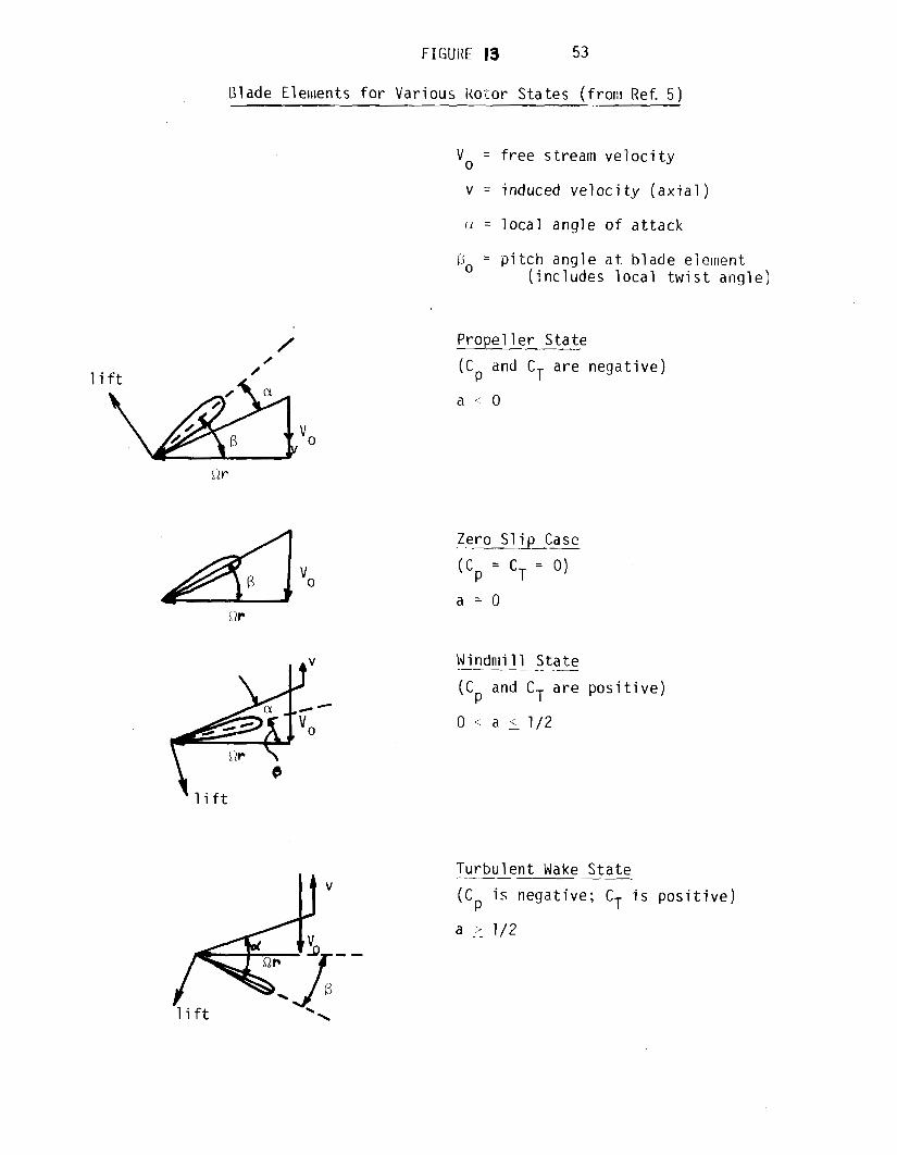
Blade E l e ~ ~ ~ e n t s f o r Var ious i t o to r S ta tes ( f r o n ~ Ref. 5 )
V o = f r e e stream v e l o c i t y
v = induced v e l o c i t y ( a x i a l )
n = l o c a l ang le o f a t t a c k
13, = p i t c h ang le a t b l a d e element ( i n c l u d e s l o c a l t w i s t ang le )
l i f t
Vo
Prope 1 1 e r S ta te
(Cp m"dC a r e nega t i ve )
Zero S l i p Case --
(C = C = 0) P T
a = O
Windnii .- 11 S t a t e
(Cp and C T a r e p o s i t i v e )
Tu rbu len t Wake S t a t e - .-
(Cp i s nega t i ve ; CT i s p o s i t i v e )
a 7/2
v i b r a t i o n and b u f f e t t i n g can occur , as w i t h h e l i c o p t e r r o t o r s .
I t i s i n t e r e s t i n g t o a l s o cons ide r t h e low RPM behav io r o f h i g h
s o l i d i t y p r o p e l l e r s , such as t h e American f a n n i i l l . A s RPM i s decreased,
t h e cor responding change i n downwash and ang le of a t t a c k i s much sma l l e r
f o r these machines; hence, l a r g e p o s i t i v e t o rque i s s t i 11 produced a t
v e r y l ow RPM, and t h e machines can 1 i t e r a l l y never be s t a l l e d by
conven t i ona l loads. A lso , i t p o i n t s o u t t h e non-necess i t y o f v a r i a b l e p i t c h on
these machines ( s t a t i c t o rque i s a l r e a d y h i g h ) . However, these machines
a r e genera l l y n o t impo r tan t f o r e l e c t r i c i t y g e n e r a t i o n s i n c e t h e o v e r a l l
power c o e f f i c i e n t s a r e sma l l , and optimum t i p speed r a t i o s a r e c l o s e t o
u n i t y . (2 )
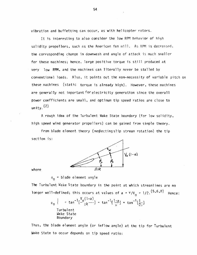
A rough idea of t h e Tu rbu len t Wake S t a t e boundary ( f o r l ow s o l i d i t y ,
h i g h speed wind gene ra to r p r o p e l l e r s ) can be ga ined from s imp le t heo ry .
From b lade element t heo ry ( neg lec t i ng s l i p stream r o t a t i o n ) t h e t i p
s e c t i o n i s :
where
4, = b lade element ang le
The T u r b u l e n t Wake S t a t e boundary i s t h e p o i n t a t which stream1 i n e s a r e no
l o n g e r we l l -de f ined ; t h i s occurs a t va l ues o f a = v/Vo = 1 / 2 . ( ~ ' ~ ' ~ ) Hence:
V (1-a) -1 0 - t a n I - -1 1-a 1 = t a n [-I = t a n
-1 1 40 n R u [GI
T u r b u l e n t Wake S t a t e Boundary
Thus, t h e b lade element ang le ( o r i n f l o w ang le ) a t t h e t i p f o r Tu rbu len t
Wake S t a t e t o occur depends on t i p speed r a t i o :

Tip Speed Ratio Turbulent Wake Boundary
9 R / V o $o a t blade t i p
TABLE 1
Most a i r f o i l s approach s t a l l a t ang le s of a t t a c k about 12". Thus, the
approximate p i t c h angle t o produce t u r b u l e n t wake s t a t e i s simply:
BO I = m o I - a s t a l l Turbulent TWS Wake S t a t e
where + I is given i n Table 1 above, and a s t a l l 1 12". -rws

References
1. H u t t e r , "Opera t ing Exper ience Obtained w i t h a 100-kW Wind Power P lan t , " NASA TTF-15, 063, August 1973.
2. Gold ing, The Genera t ion - - - . - o f E l e c t r i c i t y - . by Wind Power, -.. P h i l o s o p h i c a l L i b r a r y , 1955.
3. Rohrback and Worobel , "Performance C h a r a c t e r i s t i c s o f Aerodynamical l y Optimum Turb ines f o r Wind Energy Generators," 3 1 s t Annual N a t i o n a l Forum, American H e l i c o p t e r s o c i e t y , May 1975.
4. Deutsch, L. , Grunlman Aerospace Corpora t ion , personal comnuni c a t i o n , 19 March 1976.
5. W i l s o n and Lissnlan, "Appl i e d Aerodynamics o f Wind Power Machines ," Oregon S ta te U n i v e r s i t y , J u l y 1974.
6. Gessow and Myers, Aerodynamics .~ -- o f t h e H e l i c o p t e r , -. F r e d e r i c k Ungar Pub l i she rs , 1952.
7. Stoddard, Edds, " F i n a l Repor t on Wind Tunnel Tes t Program o f Model Blades on a 200 wa t t , 12 v o l t Wind Generator," U n i v e r s i t y o f Massachusetts, C i v i l Eng ineer ing Department In-House Report , May 1974.
8. Stoddard, "D i scuss ion of Monientum Theory f o r Windmi l l s , " ( t h i s r e p o r t ) .
9. Edds, M., " O p t i m i z a t i o n of Ou tpu t Power o f an AC Synchronous Machine by Va ry i ng E x c i t a t i o n and Load," M.S. Ocean Eng ineer ing Thes is , t o be pub l i shed , June 1976.
10. B lackwe l l , "The V e r t i c a l A x i s Wind Turb ine; How i t Works," Sandia Labo ra to r i es , Albuquerque, New Mexico, SLA-74-0160, A p r i l 1974.

UN-TTY OF MASSACi"3SElTWAhllHERST ENERGY ALTERNATIVES PROGRAM
h \ A ,
UNIVERSITY OF MASSACHUSETTS/AMHERST
ENERGY ALTERNATIVES PROGRAM
Pre l i ~ n i nary Report on
OPTIMIZING THE WINDMILL ROTOR
Paul Lefebvre
and
Duane E. Cromack
U.Mass Wind Furnace
Energy A1 t e r n a t i ves Program
U n i v e r s i t y o f Massachusetts
Amherst, Massachusetts 01002
TR/76/4 Appendix V I
OPTIMIZING THE WINDMILL ROTOR
a b s t r a c t
Twelve h o r i z o n t a l a x i s w ind r o t o r systems a r e ana lyzed by means o f computer
s i m u l a t i o n . The purpose o f t h i s a n a l y s i s i s t o d e v e l o p a method o f d e s i g n i n g
o p t i m i z e d b lades o f d i f f e r e n t r o t o r c o n f i g u r a t i o n s . The r e s u l t s o f t h e s imu la -
t i o n a r e t h e n compared w i t h w ind t u n n e l t e s t r e s u l t s .
i n t r o d u c t i o n
One o f t h e p r i n c i p a l components o f any w i n d m i l l i s t h e momentum exchange
dev ice , o r r o t o r . T h i s d e v i c e c o n v e r t s t h e k i n e t i c energy o f a moving a i r
s t ream t o a more u s a b l e fo rm o f power. There a r e two b a s i c c l a s s i f i c a t i o n s
f o r w i n d m i l l s : v e r t i c a l a x i s machines and h o r i z o n t a l a x i s machines. T h i s
r e p o r t d e a l s o n l y w i t h h o r i z o n t a l a x i s r o t o r s . W i t h i n t h i s c a t e g o r y a l l r o t o r s
t a k e t h e f o r m o f an a i r s c r e w w i t h t h e d i f f e r e n c e between d e s i g n s b e i n g i n t h e
c h o r d and t w i s t d i s t r i b u t i o n o f each b lade , and t h e number o f b l a d e s err~ployed
f o r any g i v e n r o t o r . The f u n c t i o n a l r e l a t i o n s h i p o f t h e s e v a r i a b l e s de te rm ines
how e f f i c i e n t l y a r o t o r p e r f o r n ~ s . Four d i f f e r e n t r o t o r sys tems a r e s t u d i e d
and t h e i r per formance c a p a b i l i t i e s o p t i m i z e d . The r o t o r t y p e s c o n s i d e r e d a r e :
( 1 ) c o n s t a n t chord, z e r o t w i s t (CCZT); ( 2 ) l i n e a r t a p e r e d chord, ze ro t w i s t
(LCZT); ( 3 ) l i n e a r tapered chord , l i n e a r t w i s t (LCLT); and ( 4 ) a e r o d y n a m i c a l l y
optimum c h o r d and t a p e r (OPT). The optimum b l a d e i s t a k e n t o be t h a t a i r
screw c o n f i g u r a t i o n w h i c h w i l l e x t r a c t t h e h i g h e s t pe rcen tage o f t h e power
a v a i l a b l e . I t has been shown t h a t t h e maximum power c o e f f i c i e n t o b t a i n a b l e
i s .5926, and i n p r a c t i c e C w i l l i n v a r i a b l y be l e s s t h a n t h i s va lue . To P
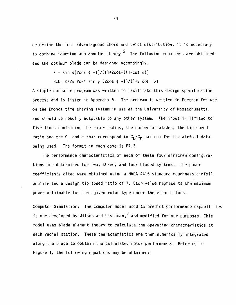
determine t h e most advantageous chord and t w i s t d i s t r i b u t i o n , i t i s necessary
2 - t o combine momentum and annulus theory . The f o l l o w i n g e q u a t i m s a r e ob ta ined
and t he optimum b lade can be designed acco rd ing l y .
X = s i n +(2cos + - 1 ) / ( ( 1+2cos+ ) ( l - cos + ) )
BcCL ~ / 2 n Vo=4 s i n + (2cos + -1) / (1+2 cos $ )
A s imp le computer program was w r i t t e n t o f a c i l i t a t e t h i s des ign s p e c i f i c a t i o n
process and i s l i s t e d i n Appendix A. The program i s w r i t t e n i n F o r t r a n f o r use
on t h e Kronos t ime sha r i ng system i n use a t the U n i v e r s i t y o f Massachusetts,
and shou ld be r e a d i l y adaptable t o any o t h e r system. The i n p u t i s l i m i t e d t o
f i v e l i n e s c o n t a i n i n g t he r o t o r r a d i u s , t h e number o f blades, t h e t i p speed
r a t i o and t h e CL and a t h a t correspond t o CL/CD maximum f o r t h e a i r f o i l da ta
be ing used. The f o rma t i n each case i s F7.3.
The performance c h a r a c t e r i s t i c s o f each o f these f o u r a i r s c r e w c o n f i g u r a -
t i o n s a r e determined f o r two, th ree , and f ou r b laded systems. The power
c o e f f i c i e n t s c i t e d were ob ta ined us ing a NACA 4415 s tandard roughness a i r f o i l
p r o f i l e and a des ign t i p speed r a t i o of 7. Each va lue rep resen ts t h e maximum
power o b t a i n a b l e f o r t h a t g i v e n r o t o r t ype under these c o n d i t i o n s .
Computer S imu la t i on : The computer model used t o p r e d i c t performance c a p a b i l i t i e s
i s one developed by Wi lson and LissamanY3 and m o d i f i e d f o r our purposes. T h i s
model uses b lade element t heo ry t o c a l c u l a t e t h e o p e r a t i n g c h a r a c r e r i s t i c s a t
each r a d i a l s t a t i o n . These c h a r a c t e r i s t i c s a r e then n u m e r i c a l l y i n t e g r a t e d
a long t h e b lade t o o o b t a i n t h e c a l c u l a t e d r o t o r performance. Re fe r i ng t o
F igu re 1, t h e f o l l o w i n g equat ions may be ob ta ined :
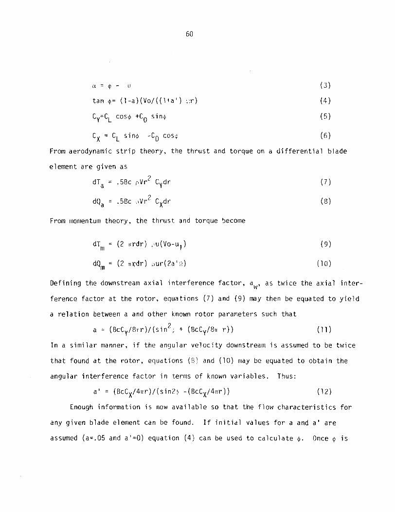
LY. = @ - I)
t a n $= ( 1 -a ) ( V o / ( ( l + a l ) ; ! r )
Cy=CL cos@ +CD s i n 4
c X = cL s i n + -cD C O S ~ ( 6
From aerodynamic s t r i p t h e o r y , t h e t h r u s t and t o r q u e on a d i f f e r e n t i a l b l a d e
e lement a r e g i v e n as
dT, = .5Bc p v r 2 Cydr
From momentum t h e o r y , t h e t h r u s t and t o r q u e become
dTm = ( 2 n r d r ) , ~ ~ ( V o - u ~ ) ( 9 )
D e f i n i n g t h e downstream a x i a l i n t e r f e r e n c e f a c t o r , aw, as t w i c e t h e a x i a l i n t e r -
f e r e n c e f a c t o r a t t h e r o t o r , e q u a t i o n s ( 7 ) and ( 9 ) may then be equated t o y i e l d
a r e l a t i o n between a and o t h e r known r o t o r parameters such t h a t
a = ( ~ c ~ ~ / ~ n r ) / ( s i n ~ ; + (BcCy/8. r ) ) ( 1 1 )
I n a s i m i l a r manner, i f t h e a n g u l a r v e l o c i t y downstream i s assumed t o be t w i c e
t h a t found a t t h e r o t o r , e q u a t i o n s (8) and ( 1 0 ) may be equated t o o b t a i n t h e
a n g u l a r i n t e r f e r e n c e f a c t o r i n terms o f known v a r i a b l e s . Thus:
a ' = ( B c C X / 4 n r ) / ( s i n 2 j - (BcCX/4nr ) ) ( 1 2 )
Enough i n f o r m a t i o n i s now a v a i l a b l e so t h a t t h e f l o w c h a r a c t e r i s t i c s f o r
any g i v e n b l a d e e lement can be found. I f i n i t i a l v a l u e s f o r a and a ' a r e
assumed (a=.05 and a l=O) e q u a t i o n ( 4 ) can be used t o c a l c u l a t e 4 . Once @ i s

known equa t i on ( 3 ) i s used t o f i n d a. For a g i ven va lue o f a , CL and CD can
be ob ta ined f rom polynomia l c u r v e f i t s o f t h e aerodynamic data. Knowing t h e
l i f t and drag c o e f f i c i e n t s , and $, equa t ions ( 5 ) and (6 ) a r e then used t o
f i n d Cy and Cx. T h i s a l l o w s f o r t h e c a l c u l a t i o n o f a new va lue o f a and a '
which a r e then used t o r epea t the e n t i r e process. The i t e r a t i o n con t inues
u n t i l convergence on a and a ' occurs.
I n p r a c t i c e i t was found t h a t a t low l o c a l speed r a t i o s t h e i t e r a t i o n
l o o p would sometimes f a i l t o converge. T h i s i s due t o t h e non - l i nea r
r e l a t i o n s h i p between a and a ' , and t h e l o c a l speed r a t i o ( F i g u r e 2 ) . Because
o f t h i s convergence problem, i t was necessary t o f u r t h e r mod i f y t h e o r i g i n a l
program so t h a t each success ive i t e r a t i o n used t h e mean va lue o f a and a '
found i n t h e two p rev ious passes. A c o r r e c t i o n f a c t o r was a l s o i n t r oduced i n
which a t l o c a l speed r a t i o s o f .75 o r below, a ' was m u l t i p l i e d by one q u a r t e r
o f t h e l o c a l speed r a t i o , and t h i s new va lue of a ' used f o r t h e n e x t pass. T h i s
f a c i l i t a t e s t h e convergence procedure.
*The c o n s t r a i n t s used i n the corr~puter s i m u l a t i o n a r e as f o l l o w s :
( 1 ) Hub r a d i u s o f 10 pe rcen t t h e b lade rad ius ,
(2 ) A s tandard a x i a l i n t e r f e r e n c e model,
( 3 ) A l t i t u d e above sea l e v e l o f 200 f e e t ,
( 4 ) No con ing ang le used,
(5 ) T i p l osses modeled by P r a n d t l ' s method,
( 6 ) No nub l o s s model used,
( 7 ) A NACA 4415 Standard roughness a i r f o i l p r o f i l e was used,
(8) A t i p speed r a t i o o f 7 was used.

Computer S in l u l a t i on - Resu l ts : - . - - - The power c o e f f i c i e n t s obtctint.d w i t h o p t ~IIIUIII
r o t o r s o f two, t h ree and f o u r blades a r e l i s t e d i n Table 1. These r o t o r s
were designed f o r a t i p speed r a t i o o f 7 , a CL o f -914, a t an ang le o f a t t a c k
o f 5.57 degrees. The l a s t two f i g u r e s rep resen t t h e p o i n t a t which C L / C D i s
maximum f o r an NACA 4415 s tandard roughness p r o f i l e .
The n e x t two b lade types t o be cons idered a r e l i n e a r chord zero t w i s t
and l i n e a r chord l i n e a r t w i s t . I n bo th cases t h e f i n a l des ign c o n f i g u r a t i o n was
found by making a s e r i e s o f corr~puter runs i n which chord and t w i s t were
s y s t e m a t i c a l l y changed i n a s e r i e s o f approx imat ions, as were f i and X, u n t i l 0
a maximum power o u t p u t a t a t i p speed r a t i o o f 7 was reached. The chord and
t w i s t approx imat ions t h a t were t r i e d a r e shown i n F i g u r e 3. I n o r d e r t o o b t a i n
a c o n s i s t e n t method o f des ign ing blades o f t h i s type, t h e i r chord and t w i s t d i s -
t r i b u t i o n s a r e l i s t e d i n Table 2 i n terms o f t he optinlum b lade o f s i m i l a r des ign
c o n s t r a i n t s .
For example, i f an LCZT 3-bladed r o t o r w i t h a r a d i u s o f 10 f e e t and a t i p
speed r a t i o o f 7 i s d e s i r e d , t h e b lade c o n f i g u r a t i o n i s found as f o l l o w s . The
optimum b lade f o r these c o n d i t i o n s i s l a i d ou t . The chord o f t h e LCZT b lade a t
100 percen t o f t h e r a d i u s i s taken as 90 percen t o f t he chord o f t h e optimum
b lade a t t h a t p o i n t . The chord o f t h e LCZT b lade a t 10 pe rcen t o f t h e r a d i u s
i s taken as 67 percen t o f t h e chord o f t h e optimum b lade a t t h a t p o i n t . As
t h e chord d i s t r i b u t i o n i s l i n e a r , t he dimensions of t h e b lade a r e now f i x e d .
A l l t h a t remains i s t o s e t t he , -o t o t h a t s p e c i f i e d i n Table 2 .
The power c o e f f i c i e n t s ob ta ined f o r LCZT and LCLT r o t o r s o f two, t h ree ,
and f o u r b lades a r e shown i n Table 1.
The f i n a l b l ade t ype t o be cons idered i s cons tan t chord zero t w i s t . For
r o t o r s o f t h i s t y p e t h e r e a r e t h r e e v a r i a b l e s t h a t w i l l a f f e c t performance:

t h e r o t o r s o l i d i t y , t h e fro s e t t i n g , and t he number o f b lades. The r e l a t i o n
between r o t o r s o l i d i t y and K~ f o r maximum power, and t he r e s u l ~ i n g t i p speed
r a t i o , i s shown i n F i g u r e 4. These curves were generated by making a s e r i e s o f
computer runs f o r a g i v e n s o l i d i t y f o r which Bo and X were s y s t e m a t i c a l l y
changed u n t i l a maxirnun~ power was obta ined. The process was then repea ted f o r
a nurnber o f r o t o r s o f d i f f e r e n t s o l i d i t i e s .
These r e s u l t s were checked t o i n s u r e t h a t they app l y f o r a g i ven r o t o r
s o l i d i t y r ega rd less o f whether i t con ta ins 2, 3, o r 4 blades. The a n a l y s i s
was then repeated us ing NACA 4418 a i r f o i l da ta i n o r d e r t o check f o r cons is tancy
between s i m i l a r p r o f i l e s .
The power c o e f f i c i e n t s t h a t can be expected f rom cons tan t chord zero t w i s t
r o t o r s w i t h two, th ree , and f o u r blades a re a l s o shown i n Table 1.
W i nd Tunnel Resul t s : I n an e f f o r t t o expe r imen ta l l y v e r i f y t he r e s u l t s o f
t h e computer s imu la t i on , a wind tunne l t e s t program was es tab l i shed . S i x model
blades were cons t ruc ted : two optimum blades and f o u r cons tan t chord ze ro
t w i s t b lades. T h i s would a l l o w f o u r r o t o r systems t o be t e s t e d and a compari-
son t o be made between severa l b l ade types, s o l i d i t i e s , and numbers o f b lades.
The t e s t arrangement i s shown i n F igu re 5. The e l e c t r i c genera to r was loaded
by means o f f o u r v a r i a b l e r e s i s t a n c e l o a d banks. For any g i ven t e s t , t he l o a d
a p p l i e d t o t h e genera to r was s y s t e m a t i c a l l y v a r i e d u n t i l t he combinat ion o f f i e l d
e x c i t a t i o n and r e s i s t a n c e were such as t o produce maximum power. T h i s power
was determi ned by measuri ng the vo l tage and amperage t o t he 1 oad (P=VI ) and
t hen adding t o t h i s t he expe r imen ta l l y determined e f f i c i e n c y l osses o f t he
generator . (see F i g u r e 6 )

For each r o t o r type, a s e r i e s o f t e s t s were f i r s t conducted t o a s c e r t a i n
t h e po s e t t i n g f o r maximum power. That s e t t i n g was then used f o r a s e r i e s o f
runs a t i n c r e a s i n g wind speeds. The i nc rease i n maximum power w i t h wind speed
p a r a l l e l e d c l o s e l y t h e expected cub i c r e l a t i o n s h i p and i s shown i n F i g u r e 6.
A l so shown i s t h e r e l a t i o n s h i p between power and RPM as a f u n c t i o n o f a p p l i e d
load. Table 3 con ta ins t h e power c o e f f i c i e n t s o f t h r e e r o t o r systems f o r
comparison w i t h t h e power c o e f f i c i e n t s p r e d i c t e d by t h e computer s i m u l a t i o n .
conc lus ion
Exper imenta l v e r i f i c a t i o n o f t h e computer s i m u l a t i o n has n o t been completed.
The d i f f e rences i n power c o e f f i c i e n t s l i s t e d i n Table 3 a r e q u i t e l a r g e w i t h
no c o n s i s t e n t p a t t e r n d i sce rnab le . A d d i t i o n a l wind tunne l t e s t s a r e p lanned
i n o rde r t o o b t a i n a b e t t e r c o r r e l a t i o n between t h e o r e t i c a l and exper imenta l
r e s u l t s . S ince t h e computer model i s based on w e l l - e s t a b l i s h e d aerodynamic
theory , t h e r e s u l t s f o r comparat ive purposes a r e c e r t a i n l y v a l i d .
The s e l e c t i o n o f t h e r o t o r type, i .e. , optimum, LCLT, CCZT, e tc . , depends
on t h e p a r t i c u l a r a p p l i c a t i o n b u t more impor tan t , depends on t h e method o f
b l ade manufacture and t h e m a t e r i a l t o be used. Th i s i s a problem of c o s t
e f f e c t i v e n e s s and n o t o f j u s t r o t o r performance.
The problem o f o p t i m i z i n g may be viewed d i f f e r e n t l y by s t a n d a r d i z i n g t h e
power o f each r o t o r system i n terms o f t h e r e q u i r e d r o t o r d iameter . Th is i s
done i n t h e f o l l o w i n g manner. For any proposed wind gene ra t i ng system t h e r e
w i l l be a r e q u i r e d power f o r a p a r t i c u l a r des ign wind speed. For t h e des ign
power and r a t e d wind speed, t he r e q u i r e d r o t o r d iameter can be c a l c u l a t e d
f rom t h e s tandard power equa t ion as D = [8P/nC The r e s u l t i s t h a t P

a two-bladed CCZT r o t o r w i t h a d iamete r 5 .27 pe rcen t g r e a t e r than a t e n - f o o t ,
d iamete r two b laded optimum r o t o r w i l l y i e l d equal power. Therefore, t h e
cho i ce t o be made i s between a t en - f oo t optimum b lade and a 10.53 f o o t CCZT
b lade. The d e c i s i o n as t o which b lade t o use i s based on which b l ade t y p e
would have t h e l owes t u n i t p r o d u c t i o n c o s t f o r t h e number o f b lades r e q u i r e d .
Tab le 4 i n d i c a t e s t h e per cen t i nc rease i n b l ade d iamete r needed f o r equal
power ou tpu t , s t anda rd i zed t o t h e optimum b lade shape.
I t shou ld be s t r essed t h a t t h e r e s u l t s c i t e d a p p l y r e a l l y o n l y t o NACA 4415
a i r f o i l p r o f i l e s , a l t hough t he r e s u l t s ob ta i ned u s i n g a NACA 4418 p r o f i l e were
q u i t e s i m i l a r . O ther b l ade s e c t i o n s need t o be analyzed b e f o r e t h i s procedure
can be gene ra l i zed .
I t should a l s o be kep t i n mind t h a t t h e power c o e f f i c i e n t s found a r e f o r
p e r f e c t l y c o n s t r u c t e d b lades. If a l i m i t e d number o f optimum b lades were t o
be produced, i t would be d i f f i c u l t t o o b t a i n t h e exac t chord and t w i s t d i s t r i -
b u t i o n needed. On t h e o t h e r hand, b e t t e r q u a l i t y c o n t r o l m i g h t be expected f o r
CCZT b lades because o f t h e s imp le r c o n s t r u c t i o n .
T h i s s tudy at tempted t o o p t i m i z e t h e chord and t w i s t d i s t r i b u t i o n o f f ou r
r o t o r t ypes . I t has been suggested t h a t f u r t h e r inc reases i n t h e power c o e f f i -
c i e n t s m igh t be ob ta i ned by such methods as v a r y i n g t h e a i r f o i l p r o f i l e a l ong
t h e blade, o r by des ign ing t h e b lade i n such a way t h a t t h e CL/CD r a t i o was a
f u n c t i o n o f t h e r a d i a l s t a t i o n i n s t e a d of h o l d i n g i t a t a cons tan t CL/CD maximum.

TAGLE 1
POWER COEFFICIENTS OF TWELVE SIMULATED ROTORS
( L i s t e d i n o rde r o f magnitude)
Type o f Rotor No. o f Blades Bo Power C o e f f i c i e n t
Optimum
Optimum
Optimum
LCLT
LCLT
LCLT
LCZT
L CZT
LCZT
CCZT
CCZT
CCZT
CCZT


TABLE 4
INCREASE OF BLADE DIAMETER NEEDED TO OFFSET LOSS OF
EFFICIENCY DUE TO USE OF A NON-OPTIMUM BLADE
% Inc rease i n Na Blades Rotor Type Power C o e f f i c i e n t Diameter @o
- - - -
2 Optimum 0.0 .439 0.00
2 LCLT 2.0 .428 1.28
2 LCZT
2 CCZT
3 Optimum 0.0 .463
3 LCLT . 1.5 .449
3 LCZT 4.5 .423 4.62
3 CCZT 6.1 .415 5.62
4 Optimum 0.0 .474 0.00
4 LCLT 1.5 .460 1.51
4 LCZT 4.5 -430 4.99
4 CCZT 6.1 .425 5.61


F I G U R E 2
0 I 2 3 4 ar5 6 7 L O C A L S P E E D R A T I O - ' V o
A X I A L A N D A N G U L A R I N T E R F E R E N C E
-
-
-
F A C T O R S v s L O C A L S P E E D R A T I O a
a
I I I I

7 2
FIGURE 3 APPROXIMATIONS USED FOR THE COMPUTER SIMULATION OF THE LCZT AND LCLT BLADES
LINEAR TWIST APPROXIMATIONS
CHORD TWIST

FIGURE 4
SOLIDITY vs P I T C H A N G L E AND T I P SPEED RATIO F O R CONSTANT CHORD Z E R O T W I S T BLADES
- - /' N A C A 4415
P o STD. ROUGHNESS
- N A C A 4418
V I I I I
.O 3 -0 6 .O 9 . I 2 S O L I D I T Y , 0-


FIGURE 6
POWER vs R.F!M. F O R 2 - BLADED OPTIMUM R O T 0 R
300 4 00 500 600 700 800 900 ROTOR R.P.M.

Nomencl a t u r e
Ax ia l i n te r fe rence f a c t o r
Angular i n te r fe rence f a c t o r
Wake a x i a l i n te r fe rence f a c t o r
Number o f blades i n a g iven r o t o r
Local chord f o r a g iven blade
Drag c o e f f i c i e n t
L i f t c o e f f i c i e n t
Power c o e f f i c i e n t
C o e f f i c i e n t o f f o r c e i n t h e d i r e c t i o n o f r o t a t i o n
C o e f f i c i e n t o f f o r c e normal t o t h e plane o f r o t a t i o n
Radius o f t he r o t o r
Radius o f a g iven l o c a l s t a t i o n
Ax ia l f l o r v e l o c i t y a t t he r o t o r
Ax ia l f l o w v e l o c i t y i n the wake
Torque as g iven by aerodynamic theory
Torque as g iven by momentum theory
Thrust as g iven by aerodynamic theory
Thrust as g iven by momentum theory
Free stream ve l oc i t y
The r e l a t i v e v e l o c i t y as seen by a moving blade element
The t i p speed r a t i o o f the r o t o r devined as nR/Vo
The angle between the chord of t he blade element and the r e l a t i v e v e l o c i t y
An equal angular de f l ec t i on , i n a d d i t i o n t o blade t w i s t , g iven t o each blade element

n Angular v e l o c i t y o f the r o t o r
p Densi ty o f t h e f l u i d medium
Angle between the plane o f r o t a t i o n and the r e l a t i v e v e l o c i t y
e Angle between t h e plane o f r o t a t i o n and t h e chord o f t h e b lade element.
references
1. Glaver t , H., Aerodynan~ics Theory (IJ. F. Durand, Edi t o r - i n - C h i e f ) , Vol . I V ,
D i v i s i o n L, J u l i u s Springer, B e r l i n , 1935.
2. i b i d
3. Wilson and Lissaman, "Appl ied Aerodynamics o f Wind Power Machines," Oregon Sta te Un ive rs i t y , J u l y 1974.
4. Putnam, P. C., Power from the Wind, Van Nostrand Company, Inc . , New York, 1 948.

APPENDIX P
LNH
0 0 1 0 0 P??OG??AI.1 O?T < IPJP'JT J O'!T?'.!T 0 0 1 0 5 DIME?I .SIC?I C E ( 1 5 ) 0 0 1 1 8 ?EAD l r ?. 0 0 1 2 0 ?EAD l r B 0 0 1 3 8 ?EA9 l r X 0 0 1 4 3 FZAD l r CL 0 0 1 5 8 ?EAD l r A 0 0 1 6 0 1 F O ! ? ! A A ( F 7 * ) @ 0 1 7 E ??IN? 2 0 0 1 68 2 FC?MAT<//SXJ*?AD I U S * r S Y r * ? C ~ R * J ~ Y , * B C C L ~ / ~ ? I ~ * , ~ ~ , * ? H I * J ~ ~ J *EO*rS 0 0 1 9 8 + X r *CH03D*/) 0 0 2 0 0 ?1=3 1 4 1 5 9 2 0 5 4 0 0 2 1 0 FiL=O* e 0 2 2 0 XL=E?* 0 0 2 3 0 ?E?!=a* 0 0 2 4 0 ?=60* 0 0 2 4 1 D A = ? I * ( ? * * 2 * > 0 0 2 4 5 v=? . / i e . 0 0 2 5 0 DO 3 2 L-1 J 1 0 0 0 2 6 0 Y L = Y L + ( Y / l B m > 0 0 2 7 0 P = ? * P I / l E B * E 0 2 8 8 ! ? L = ! ? L + ( ? / l a * ) 0 8 2 9 3 ?E?=?E"+*l 0 0 3 0 0 DO 5 I = 1 ~ 6 0 0 C 0 0 3 1 0 P = ? - < * C l * ? I / 1 8 3 * > 0 0 3 2 0 XE=(SI?I(?>*(2**CCC(?>-l*>)/<(l * + 2 e * C O ~ ( ? > > * ( l * - C G S ( P ) ) ) 00330 I F ( A S Z ( : < L - X E > * L T * * 2 5 > G O TO 6 0 0 3 3 2 5 COM?IP!!!E 0 0 3 3 4 6 DO 7 J - l r 4 D 2 2 0 0 3 3 6 ?=? -< .C!Ol*? I / lE !?~> 00338 YE=<SI~l<??*(2~*C@S<?>-le > > / ( ( I * + ~ * * C O S ( Q ) ) * ( I * - C O S ( ? ) ) ) 0 3 3 4 8 IF<ASC. (YL-XE) e L T * e Z C 5 ) G O TO IO 0 6 3 4 2 7 COP!TIN'JE 00358 l e 9CCL=<4**sIN<?>*(2**CC5(?)-1 ) > / ( I * + 2 * * C G S ( ? ) ) 0 0 3 6 E ?=F* l EO * / ? I 0 8 3 7 8 EO=?-A 0 0 3 8 9 C,!(L)=BCCL/(E*CL*:'/(2 . *? I*?> 1 0 0 3 9 0 PDI?J? 2 8 1 ? . L r ? E ? ~ 3 C C L r ? r 9 3 r C : i ( L > 0OGL34? 2 2 FC?.??Ar<SY, i 6 . 2 J 5 ? : , F L I . ~ ~ S : - , F E * ~ J S Y , F C * ~ J ~ Y ~ T S * ~ ~ ~ Y ~ F ~ * ~ > 0 0 4 1 P 3 2 C CPIT I P!','S 0 Q 4 2 0 S'.TY=CH(l ) + 3 * * C H ( 2 ) + 3 * * C H ( 3 > + 2 * * C : E ( 4 ) + 3 * * C t i ( 5 > + 3 * * C H ( 6 > + 2 * * C F . ( 7 ) 0 0 4 2 1 + +3 * r * C 1 ! ( 8 > + 3 * * C H < 3 ) + C 1 ? ( 1 0 > a 3 4 3 0 8A?EA=( ( 3 **E*S!!:4) / S * >*3 0 0 4 4 0 S I GCL=BA?.EA/DA m 4 5 3 ??I!?T 4 2 1 a A ? z A 0 0 4 6 3 4 Q FOE?-!AT(/ /3Yr*TCTAt '3LSC.E A?EA MINUS H U 3 OF * l ? = * r F 7 * 2 r * S n * F T * * ) 0 8 4 7 8 !'?IN- 5 2 r YIGCL 0 G 4 8 3 50 FO??IAT<//3?',*$ IG:.!A T c 7 A L = * r F 6 * 4 ) 0 0 4 9 8 END 2EP.DY

UNIVERSITY OF MASSACr:;JSETTS/'AMHW ENERGY ALTERNATNES PROGRAM
UNIVERSITY OF F1ASSACHUSETTS/AMHERST
ENERGY ALTERNATIVES PROGRAM
FIELD COtiTROLLER FOR THE UMASS WIND FURNACE
by
Danie l Handmann
U.Mass Uind Furnace
Energy A l t e r n a t i v e s Program
U n i v e r s i t y o f Massachusetts
Amherst, Massachusetts 01002
TR/ 7 6 / 5
Appendix V I I
FIELD CONTROLLER FOR THE UMASS WIND FURNACE
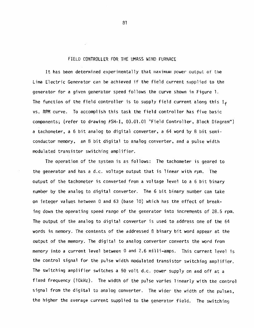
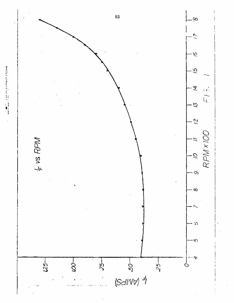
It has been deterrni ned experilnental l y t h a t III~X~II~UIII power output o f t he
Lima E l e c t r i c Generator can be achieved i f the f i e l d c u r r e n t suppl ied t o the
generator f o r a g iven generator speed f o l l o w s the curve shown i n F igure 1.
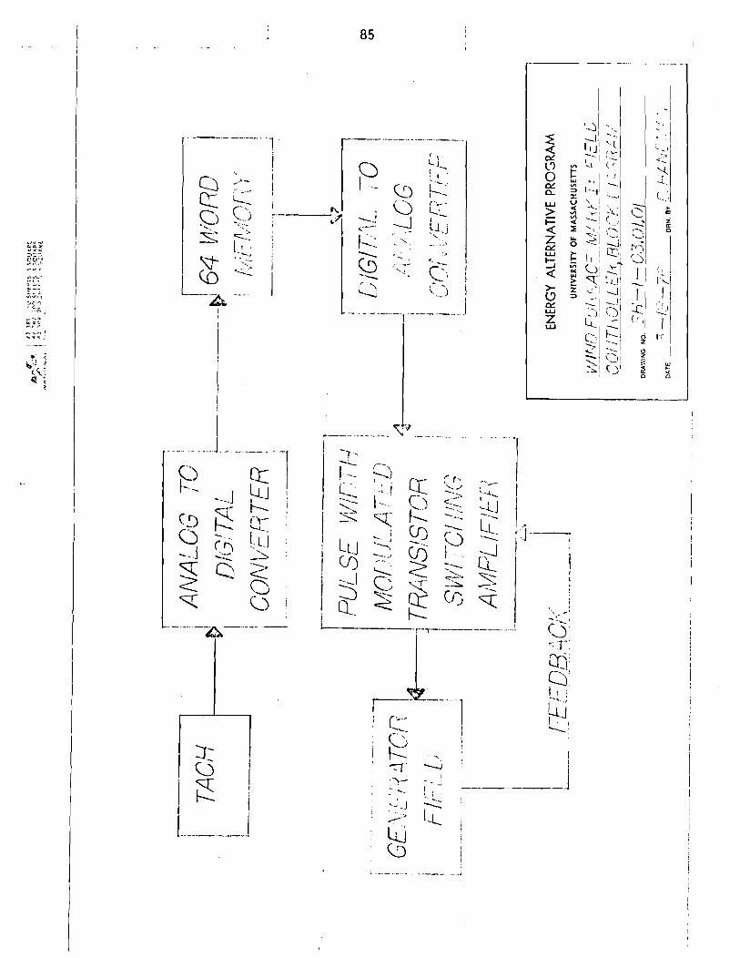
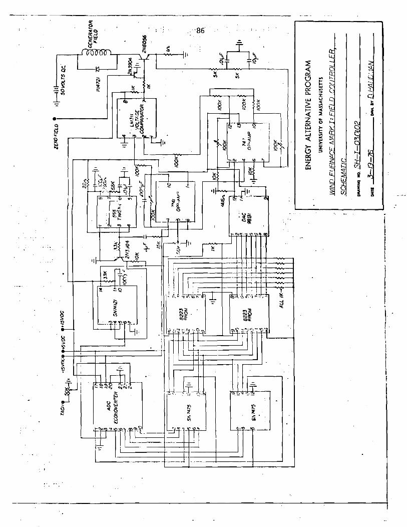
The func t ion of t h e f i e l d c o n t r o l l e r i s t o supply f i e l d c u r r e n t along t h i s If
vs. RPM curve. To accomplish t h i s task the f i e l d c o n t r o l l e r has f i v e basic
components; ( r e f e r t o drawing #SH-I, 03.01.01 " F i e l d C o n t r o l l e r , Block Diagram")
a tachometer, a 6 b i t analog t o d i g i t a l converter , a 64 word by 8 b i t semi-
conductor memory, an 8 b i t d i g i t a l t o analog converter , and a pu lse w i d t h
modulated t r a n s i s t o r swi tch ing amp1 i f i e r .
The opera t ion o f the system i s as fo l l ows : The tachometer i s geared t o
the generator and has a d.c. vo l tage output t h a t i s l i n e a r w i t h rpm. The
ou tpu t of t h e tachometer i s converted f rom a vo l tage l e v e l t o a 6 b i t b ina ry
number by the analog t o d i g i t a l converter . The 6 b i t b ina ry number can take
on i n t e g e r values between 0 and 63 (base 10) which has the e f f e c t o f break-
i n g down t h e opera t ing speed range o f t he generator i n t o increments o f 28.5 rpm.
The output o f t he analog t o d i g i t a l converter i s used t o address one o f the 64
words i n memory. The contents o f the addressed 8 b ina ry b i t word appear a t the
output o f t he memory. The d i g i t a l t o analog conver ter converts the word from
memory i n t o a cu r ren t l e v e l between 0 and 2.6 m i 11 i-amps. This c u r r e n t 1 eve1 i s
the c o n t r o l s igna l f o r the pulse w i d t h modulated t r a n s i s t o r swi tch ing a m p l i f i e r .
The swi tch ing a m p l i f i e r switches a 50 v o l t d.c. power supply on and o f f a t a
f i xed frequency (10kHz). The w id th of t he pulse va r ies l i n e a r l y w i t h the c o n t r o l
s igna l from t h e d i g i t a l t o analog converter. The wider the w id th o f the pulses,
t h e h igher the average c u r r e n t suppl ied t o the generator f i e l d . The swi tch ing

amp l i f i e r a lso monitors the amount o f cur rent being del ivered t o the generator
f i e l d by means o f a feedback loop. The feedback s ignal i s sumed i n t o the
cont ro l signal t o provide current regula t ion necessitated by the f l u c t u a t i o n
o f the generator f i e l d ' s resistance w i t h changes o f f i e l d temperature.
By bu i l d i ng the system around a memory, a c e r t a i n amount o f f l e x i b i l i t y
i s introduced i n t o the system. If, for example, i t i s determined during tes ts
o f the wind generator t h a t a d i f f e r e n t If vs. RPM curve should be used, the
o l d memory can be unplugged and replaced by a d i f f e r e n t l y programed one. For
the f i r s t model o f the f i e l d con t ro l le r , two 32 word memories were used
instead o f one 64 word memory. This provides the opt ion o f changing p a r t o f
the If vs. RPM curve a t one-half the cost. The If vs. RPM curve can a lso be
s h i f t e d hor i zon ta l l y and v e r t i c a l l y by ad just ing t r imner potentiometers i n -
cluded i n the c i r c u i t . The actual output o f the f i e l d con t ro l l e r i s shown
superimposed over the ideal If vs. RPM curve i n Figure 2.

.-.- ---- .. . . --- - - - -. - . - - . - . .-.- - . - I , . .
. -
.
.- - - --- ---- i I I
I i
-- - -. . . .- -
I ! ---.. . .. -- ,. Tg . -- ... . -- . . . . - -
j -7 - -L ,.--..,
1
I I ."
?< or I < , r- , y-I .., --.. I-:.; c;, -.- - . k i j
cr, 0- I.. , y --. 7-. - ! - \ '- - L-C ' . : j --7 I
\ .LJ 0 ;_. , I -... ; 9 g- -- ! LLJ clj i - . 4 1 --A ,, -2 : I I
.\ / W ) c ; Z , g a t I c; .< + -A t E I I i c i I T oi lu 4 f f ( c * i 1
I
i -.- i.
I j
I i '
I I ... 1 ! j a j

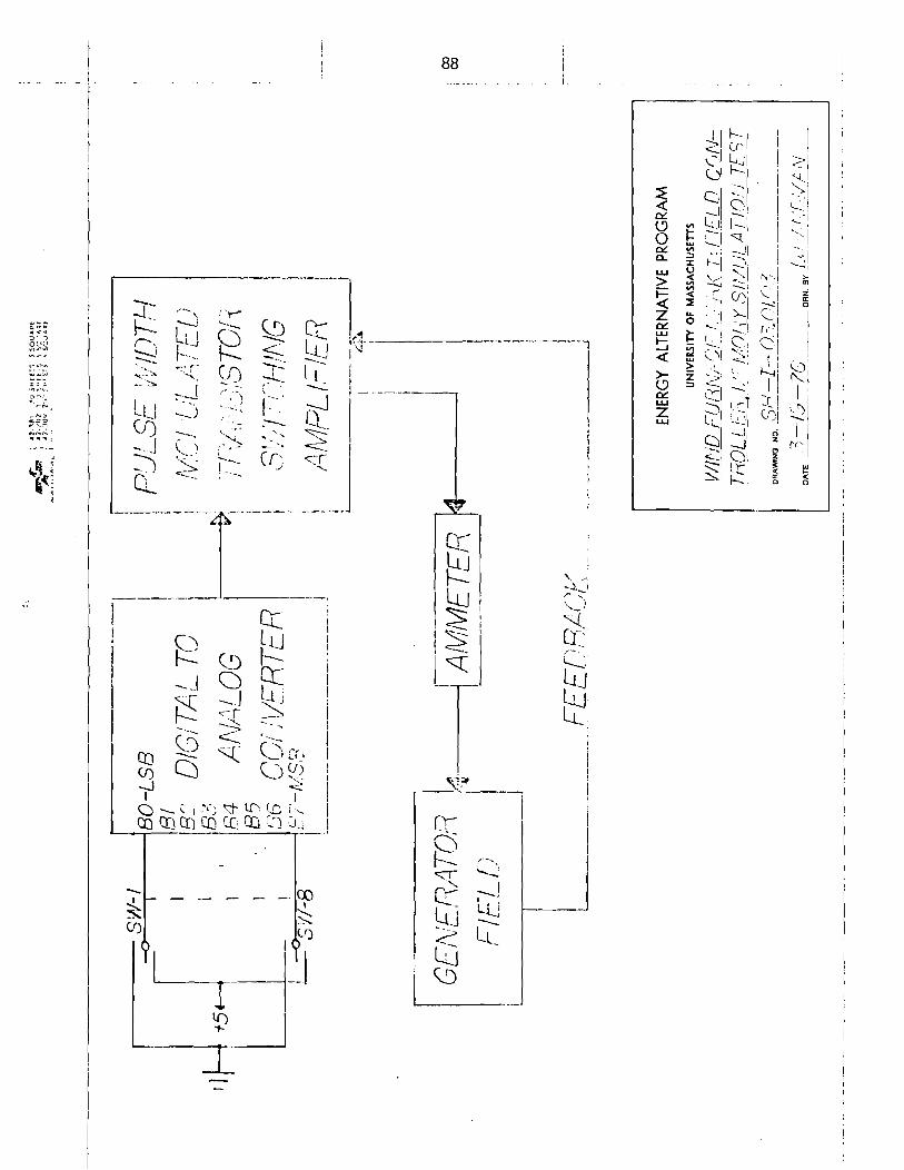
APPENDIX I : Determination of the Memory Bit Structure
In order t o determine the proper b i t pattern t o be programmed into the
memory to match the If vs. RPM curve, i t was necessary t o f i r s t determine
the output current of the f i e l d control ler c i r c u i t fo r every possible value of
a memory word. Since each word contains 8 b i t s of information, each word can
have 256 d i f fe ren t values. To find the output current t ha t would r e s u l t fo r
each of the 256 possible combinations of b i t s in a word, the following t e s t s
were run. ( r e f e r to drawing kSH-1-03.01.03, "Field Control 1 e r , Memory Simula-
t ion Test") The memories were simulated with 8 s p d t switches t ha t connected
each input of the d ig i t a l t o analog converter t o e i t he r +5 vol t s ( logical 1 )
or ground (lobical 0 ) . Then the switches were s e t fo r a l l of the 256 possible
combinations of the 8 b i t s , and with an ammeter, the resul t ing current delivered
t o the generator f i e ld for each combination was recorded. Cornb-ining the
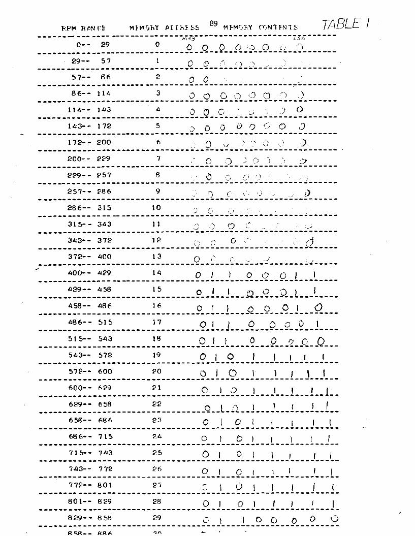
r e su l t s of the memory simulation t e s t with a l i s t i n g of the rpm range tha t each
memory word would cover, and the ideal If vs. RPM curve, the proper memory
contents t o generate the desired shape fo r the I f vs. rpm curve were determined.
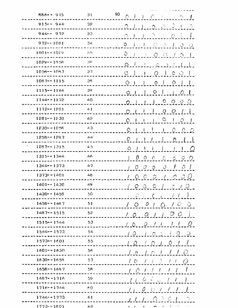
A copy of the b i t s t ruc ture i s shown in Table 1. The memories were programmed
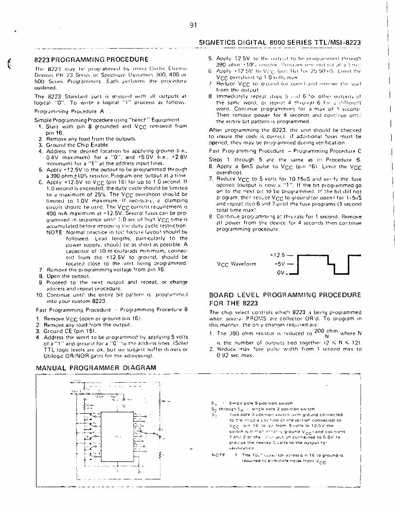
using the Signetics 8223 Programming Procedure A , a copy of which i s provided.
RPV RPN f:E MLMrJhY PIrhESS 89 MFMGhY CCvPJ'IFN 7 S ------- --- ---- - - - - - - - - - - - - - - - - - . - - - - - - - - - - - - - - - - - - - - - - - - - - - - - m 5 3 L 5 rl
0- - 29 0 . --. 0 0 0 0 - 3 0 2 . . 1 --- ---- ....................................... - 29-- 5 7 1 fi :-: ,,-, ;> ,
----.--------c---------.---------------.---------------------
5 7 - - 86 2 0 0 ---------------.-.---- ....................................... 86-- 114 3 13 a G i-.I> i3 (3 ."J ,~I ... -....-- .-------------.---.----.------------------------------
- SlGNETlCS DIGITAL 8000 SERIES TTL/MSI-8223
~- - ~-
8223 PROGRAMMING PROCEDURE Tl~cs 111;1:3 I ~ I , I ~ 1 ~ ' (r1o(ll;1n1rr11~0 I l y 11511111 ( : t ~ r t~< C11'1:trc)
Dr.v~cc:s PC1 73 S~IIC:, 01 S~II!CIIIIIII D~II,I~~II~.', 300. 400 ~ 1 1
500 So~les P~ograni~~,crs. E,~cl, i ~ c r l o ~ ~ n s [he ~~ ro~- t *du re outl~ned.
The 8223 Standard part 1s sll~l,p:d w ~ t l i a l l outputs at log~cal "0". To wrtte a log~cal "I" proceed as follow$.
Programming Procedure A ,
Simple Programming Procedure uslng "bench" Equ~pment 1. Start with pin 8 grounded and VCC removed from
pin 16. 2. Remove any load from the outputs. 3. Ground the Chip Enable. 4. Address the desired locat~on by apply~ng ground (1.e..
0.4V maximum) for a "0". and +5.OV (1.e. +2.8V minimum) for a "1" at the address input l~nes
5. Apply +12.5V to the output to be programmed through a 390 0hm210?~ resistor. Program one output at a tlme.
6. Apply +12.5V to VCC (pin 16) for up to 1 0 second. If 1.0second is exceeded, the duty cycle should be l ~ r n ~ t e d to a maximum of 25%. The VCC overshoot should be l~mited to 1.OV maxlmum. If necessnrv, a clamping c~rcuit should t~e used. The VCC currerlt rec;u~rement IS
400 m A maxi rn~~m at +12.5V. Several fuses can be pro- grammed In sequence u n t ~ l 1.0 s~ of h ~ y h VCC time IS
accumulated before Irnposllig tlio duty cycle restrrction NOTE. Normal pract~ce in test f~xture l ~ y o u t should b t
followed. Lead lengths, particularly to the power supply, should t ~ e as short as possible. A capaciror of 10 m~crofarads mlnlmum, connec- ted from the +12.5V to ground, should be located close to the unlt I h n g arogrammed.
7. Remove the proyrammingvoitaye from pin 16. 8. Open the output. 9. P~oceed to the next outpot and repeat, or change
address and repeat procedure. 10. Cont~nue u n t ~ l the entire b ~ t pattern 1s programme,.j
into your custom 8223.
Fast Programming Procedure - Programm~ny Procedure B
1. Remove VCC (open or ground pln 16). 2. Remove any load from the output. 3. Ground CE (pin 151. 4. Address the word to be programmed by applyirrg 5 volts
of a "1 " and ground for a "0" to the address l~nrs (Solid TTL log~c levels are ok, but wtb sugyest buffer dl lvers or Utilogic ORINOR yares for the atldress~ng).
MANUAL PROGRAMMER DIAGRAM
5. Al,()ly 12 5V to tht. c)lrtr..t~l to 111. rrroqr,~rr,ni~~tl rhrouc~ti 3 1 1 0 " l t \ l t l l l 1 ' 1 0 1 ) 1 . 1 1 1 1 0 1 1 l ' 0 1 1 1 1 l 1 1 1 ,If .I 111111.
6. Al)i)ly 4 17 5V to V(:C ( 1 1 1 r l I ( ; \ I t ~ r 7 5 50111:> LI~ I I I I 1 \11>
vcc 0vt'l5/10111 1 0 1 0 vt1lts rl1;lY
7 . Reduce, VCC to qr otlritl (or ol)c,rii ~ r ~ t l Il*nli)vc3 111t. lodtl from the output.
8. lmmedialcly repedl stt!l~s 5 ',I~C! 6 for other otrtl~urs o f the samt wortl, or rellt.at 4 th~ouqti 6 for a clhfterent word. Con~~nue programming for a man of 1 second. Then remove power for 4 seconds and cont~nue unlil the entire b ~ t pattern IS programmed
After programming the 8223, the unit should be checked to Insure the code is correct. If add~t~onal fuses must be opened, they may be programmed dur~ng verification.
Fast Proyramm~ng Procedure - Programming Procedure C
Steps 1 through 5 are the same as ~n Procedure B 6 Apply a 5mS pulse to VCC (pin 16) L l m ~ r the VCC
overshoot 7. Reduce VCC to 5 volts for 10 15uS and verlfy the fuse
opened (output I S now a "1" I f the hrt programmed go on to the next b ~ i to be programmed I f the b ~ t d ~ d not program then reuvce VCC to ground (or open1 for 1-5uS and repea: rtea 6 .,nd 7 u n t ~ l the fuse proglams ( 1 second total tlme maxi
8 Cont~nue progiammlng a: thls rate for 1 second Remove all power from the device for 4 seconds then contlnue programmlng procedure
VCC Waveform
BOARD LEVEL PROGRAMMING PROCEDURE FOR THE 8223 The c h ~ p select controls which 8223 IS be~ng programrced when several PROPAS are collector OR'd To program In th~s manner the 071y changes requlred are
1 The 390 ohm res,stor IS reduced to 200$hm where N
IS the number of outl~uts Ired together (2 < N < 12) 2 Reduce rnax fuse pu i s~ w ~ d t h from 1 second max to
0 92 sec maz
. I.. I, V d-~ - -.-T--r.--- - 7
7 -- I
P . 3
4 L I , I
I
1 t L i .-- -.-A ,
&
S, - Sangle po le 9 posttlon sw11ch
S 2 th rough S 6 - song!c oo le 2 por~tlon s i v l l c h
5, T w o pole 3 posttmon s w i t c h i v ! t h ground c o n n e c t e d
10 t h e r n , ~ : b e co r ? ion c l the sec l !on c o n n e c t e d to
V C C p ln 16 10 ~c f rom 5 v o l l s l o 1 2 . 5 V l h e
s i v . l i h W , I I T C - i - : a : e ~ y ground V C C i and pos!ttons
1 a n 2 2 01 t h e - :'-L- s e c t cn c o n n e c t e d t o 5 OV t o
p r o v ~ a c t h e nerJec 5 b o l t s to t h e output Tor
~ ~ ~ I ~ I C ~ T I O A
N O T E 1 Tne IS , . ' ~ ~ ? a ; , t o : azrnss omn 16 t o ground 8s reau l red tc el!mlna:e nctse f rom V C C .

UNNERSlTY OF MASSACi-:;ISm/MHm ENERGY MTERNAtlVES PROGRAM
h C 4
UNIVERSITY OF MASSACHUSETTS/AMHERST
ENERGY ALTERNATIVES PROGRAM
A GENERAL DESCRIPTION OF THE BLADE-PITCH CONTROLLER
by
Bruce A. Caccamo
U .Mass. W i nd Furnace
Energy A l t e r n a t i v e s Program
U n i v e r s i t y o f Massachusetts
Amherst, Massachusetts 01002
TR/76/ 6
Appendix V I I I
A GENERAL DESCRIPTION OF THE BLADE-PITCH CONTROLLER
Abst rac t
The b lade-p i tch c o n t r o l l e r provides f o r maximum energy t r a n s f e r between
t h e wind and the w indmi l l under vary ing wind cond i t ions . The purpose o f t h i s
paper i s t o d e f i n e t h e necessary regions o f c o n t r o l and t h e methods which
permi t s tab le opera t i on through b lade-pi t c h c o n t r o l .
The b lade-p i tch c o n t r o l l e r provides f o r maximum energy t r a n s f e r between
t h e wind and the w indmi l l under vary ing wind cond i t i ons . I n order t o under-
stand how t h e c o n t r o l l e r does t h i s , we must f i r s t look a t t h e o v e r a l l s t r u c t u r e .
The windmi l l i s f r e e t o r o t a t e i n yaw on a p l a t f o r m so t h a t the blades
a re always fac ing i n t o the wind. Thre are th ree blades, which are c o n t r o l l a b l e
i n p i t c h . The r o t o r i s connected through a speed-up d r i v e t o a 25 kW generator.
Re la t i ve t o windspeed the re a r e f o u r d i s t i n c t regions o f p i t c h c o n t r o l . I n
reg ion 1 (0-5 mph) the p i t c h c o n t r o l l e r w i l l be c a l l e d upon t o p o s i t i o n the
blades a t an angle o f a t t a c k which w i l l p rov ide the g rea tes t s t a r t i n g torque.
For these wind speeds, the p i t c h angle i s s e t a t minus e i g h t degrees. I n
reg ion 2, (5-26 mph) t h e c o n t r o l l e r w i l l ma in ta in the p i t c h angle a t minus
e i g h t degrees. This w i l l b r i n g the generator up t o speed i n t h e sho r tes t
poss ib le t ime and w i l l d e l i v e r the maximum power a t any g iven wind speed. I n
reg ion 3 (26-45 mph) the con t ro l l e r mainta ins the generator speed a t 1800 RPM.
Without t h e c o n t r o l l e r , t he generator would overspeed and t r i p o f f t he l i n e .
I n r e g i o n 4 (above 45 mph) the c o n t r o l l e r has t o fea the r the w indmi l l blades.
Th is amounts t o s h u t t i n g down the system t o prevent d e s t r u c t i o n under h igh winds.

Through computer ana lys is , t he power output curve has been r e l a t e d t o
p i t c h angle through the t i p speed r a t i o (see b lade-p i tch schedule, F igure 1 ) .
The t i p speed r a t i o (nR/V) i s the ac tua l c o n t r o l s igna l used i n the p i t c h -
c o n t r o l c i r c u i t r y t o represent the des i red p i t c h angle.
As the f o u r con t ro l regions are transversed, the t i p speed r a t i o w i l l
increase from 0 t o 7 and then decrease t o 0. As wind speed increases from
0-5 mph, the t i p speed r a t i o increases u n t i l i t reaches 7 . This p o i n t
represents the beginning o f reg ion 2 where generator RPM w i l l increase w i t h
increas ing windspeed. Throughout t h i s reg ion the blade p i t c h w i l l be maintained
a t ~ i l inus e i g h t degrees which i s equ iva len t t o QR/V = 7 . A t 26 nlph the generator
w i l l reach r a t e d RPM, and i iR /V w i l l s t a r t t o decrease as wind speed increases.
Th is occurs because the tachometer ou tput i s clamped a t 20 v o l t s . Thus, as
wind speed increases, nR/V w i l l decrease and b lade-p i tch w i l l increase u n t i l
reaching the feathered p o s i t i o n a t a windspeed o f 45 mph. I t should be noted
t h a t t h e con t ro l 1 er can be commanded t o fea the r sooner i f des i red (see Dwg.03.
02.01 ).
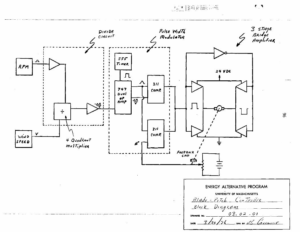
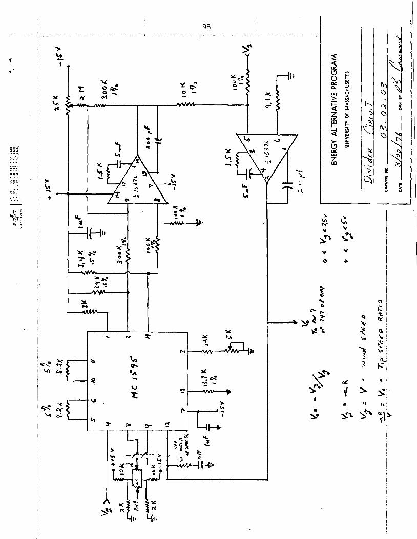
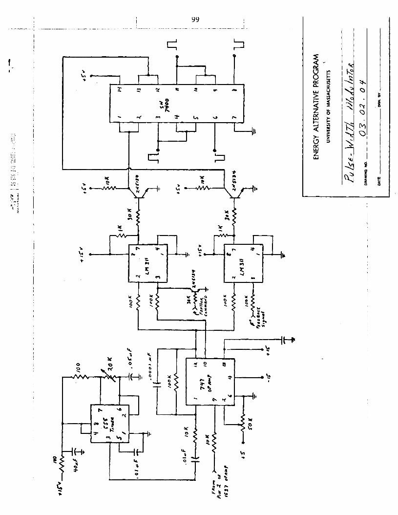
The p i t c h c o n t r o l l e r i s a c t u a l l y a pu lse-wid th modulated (PW) t r a n s i s t o r
sw i t ch ing amp l i f i e r . (see Dwg. 03.02.01) I t uses a DC power supply which
the a m p l i f i e r switches on and o f f a t a f i x e d frequency. The wider the w id th
of t h e d r i v i n g pulse; the h igher w i l l be the average c u r r e n t de l i ve red t o the
motor; and the f a s t e r the motor w i l l tu rn . PWM provides a cont inuous f i n e
c o n t r o l o f the p i t c h angle.
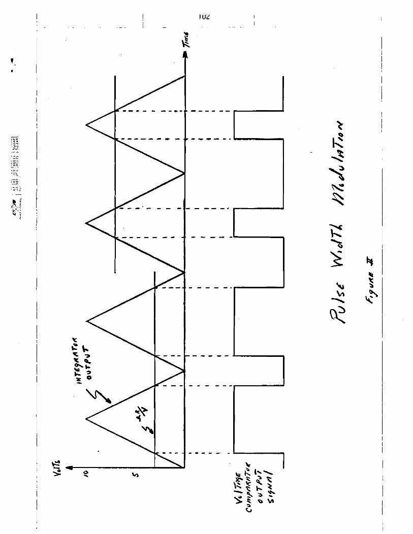
Pul se-width modulat ion i s obta ined by comparing the des i red p i t c h angle
s igna l (nR/V) w i t h a t r i a n g l e wave. The t r i a n g l e wave i s obta ined by i n t e -
g r a t i n g a square wave. The leng th of t ime i n which the vo l tage l e v e l o f the

t r i a n g l e wave i s g rea te r than t h a t of R / V determines t h e w i d t h o f t h e d r i v i r ~ g
pu l se (see F igu re 2 ) . A s i m i l a r comparison i s made between t h i s same t r i a n g l e
wave and a feedback s i g n a l which represents t h e a c t u a l p o s i t i o n o f t h e b lades.
These two pu lse-w id th modulated s i g n a l s a r e then compared ( t hey a r e 180 degrees
o u t o f phase w i t h each o t h e r ) ; thus, p r o v i d i n g the d r i v i n g s i g n a l f o r t he
motor. The motor w i l l t u r n i n t h e d i r e c t i o n which w i l l equate t h e ac tua l
ang le w i t h t h e des i red angle.
, , , > , : n l . l , I . . .
I ENERGY ALTERNATIVE PROGRAM UNIVERSITY OF MASSACHUSETTS


UNNERSITY OF MASACHUSElTS/AMHERST ENERGY ALTERNATIVES PROGRAM
UNIVERSITY OF MASSACHUSETTS/AMHERST
ENERGY ALTERNATIVES PROGRAM
PRELIMINARY REPORT
THERMAL SYSTEMS
WIND FURNACE PROJECT
Jon G. McGowan and
Ghazi Da rkaza l l i
U.Mass. Wind Furnace
Energy A l t e r n a t i v e s Program
U n i v e r s i t y o f Massachusetts
Amherst, Massachusetts 01 002
A p r i l 1975
TR/76/ 7
Appendix I X

Work in the area of thermal systems can be divided into two categories:
analytical model ing work and experimental work. The analytical modeling has
formed the basis for the experimental design and a summary of i t s key
points follows. (With the completion of the economic p a r t of th i s work,
a more detailed technical report on th i s subject will be issued.)
1. ANALYTICAL MODEL
A. Description of the Overall System Configuration
The analytical model i s based on a mathematical simulation using
a digi tal computer t o determine the feas ib i l i ty and performance of
using w-ind heating systems for home heating and domestic hot water
demands. Also, the possibili ty of combining the wind systems with a
f la t -p la te solar collector sub-system i s investigated. The basic wind
energy input component for a l l systems i s a horizontal axis wind machine.
The performance of the heating systems, for a given s i t e and
weather conditions, i s studied as a function of the following key
system parameters: 1 ) the wind generator blade diameter, 2 ) the wind
generator tower height, 3 ) the size of the residential heating del ivery
system, 4 ) the size of the solar collector, and 5 ) the s ize of the thermal
storage water tank. A detailed economical analysis of the total cost,
for each of the systems studied will be based on the assumption of mass
produced unit manufacturing. The description of the different system
model s fol 1 ows.
Model I i s the simplest windpower system (Fig. 4 .1 ) . I t has no energy
storage and electr ical energy i s delivered t o the house direct ly from the

wind generator using e lec t r i c baseboard heaters. In case there i s not
enough e lec t r i c energy generated t o keep the house a t room temperature
an auxiliary heating system i s switched on. If a t any time the e lec t r ic
energy generated exceeds the house heating demands, the excess energy i s
used fo r domestic hot water heating (optional).
( 2 ) Model 11.
In addition t o the wind generator t h i s system (Fig. 4.2) has a
water thermal storage and a liquid to a i r baseboard heaters. This
system's operational procedure i s similar t o Model I except that the
electr ical energy from the wind generator i s transferred to the storage
t a n k by means of resistance heaters. Heat then i s delivered from the
storage t o the house by circulating hot water through the baseboard
heaters.
13) Model 3-A.
This system has two energy sources and one thermal storage (Fig. 4.3).
A f l a t plate solar collector sub-system i s added to the wind system
described in Model 11. This collector sub-system consists of a f l a t
plate col lector , a water-to-water heat exchanger and a circulating pump.
Both wind and solar energy collected are delivered t o the storage tank
and then, using the same heat delivery system as in Model 11, thermal
energy i s transferred t o the house.
(4) Model 3-B.
This system i s similar t o Model 3-A except t h a t th is model uses two
separate thermal storage tanks (Fig. 4.4), one fo r wind energy and the
other fo r solar energy. In order t o operate the collector a t i t s highest
efficiency, th is model gives priori ty to delivering energy from the solar
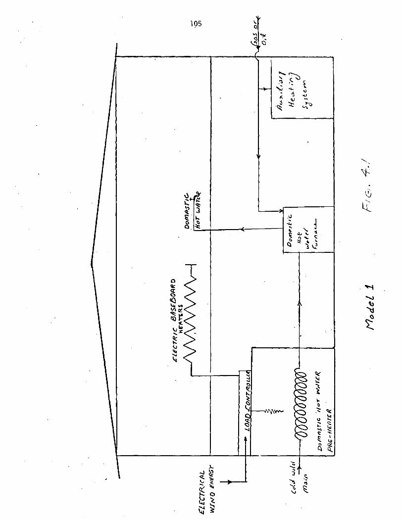

s to rage tank t o t h e house. When the temperature of the s o l a r s to rage
i s l e s s than the d e s i r e d lower l i m i t , t hen t h e system w i l l d e l i v e r energy
f rom t h e wind s to rage tank. The two s to rage tanks a r e connected t o
each o t h e r v i a a m ix ing pump which i s used when t h e temperature o f one
o f t h e s to rage tanks i s h i ghe r than the upper l i m i t .
( 5 ) Domestic Hot Water Nodel.
Th i s model i s used, i n c o n j u n c t i o n w i t h t h e p rev ious models, t o
i n v e s t i g a t e t h e p o s s i b i l i t y o f u s i n g t h e wind and s o l a r systems t o
p rov ide t h e domest ic h o t water requi rement of a r e s i d e n t i a l home.
B. System Components D e s c r l p t i o n
Since t h e o v e r a l l system performance i s a f u n c t i o n o f each i n d i v i d u a l
component, a d e t a i l e d p h y s i c a l model and mathematical a n a l y s i s has been
developed f o r t h e f o l l o w i n g bas ic components: t h e e l e c t r i c wind genera to r ,
t h e f l a t - p l a t e s o l a r c o l l e c t o r , t h e thermal water s to rage tank, t h e
house, and the baseboard heat exchangers. Also, i t inc ludes a d e r i v a t i o n
of t he maximum windpower de l i ve red by a wind genera to r as a f u n c t i o n o f
t h e wind v e l o c i t y , genera to r b lade diameter, and genera to r e f f i c i e n c y .
I n a d d i t i o n , based on a v a i l a b l e data, t he u s e f u l s o l a r energy i s determined.
A lso, an energy balance equat ion f o r t h e c o n t r o l volume around a s to rage
tank i s de r i ved . The h o u r l y hea t i ng demands a r e c a l c u l a t e d u s i n g bas ic
p r i n c i p l e s o f thermodynamics and heat t r ans fe r , and s tandard ASHRAE
p r a c t i c e . The amount o f hea t t r a n s f e r r e d t o t h e house by t he hea t d e l i v e r y
system i s c a l c u l a t e d as a f u n c t i o n of t he s i z e and c h a r a c t e r i s t i c s o f t h e
i n t e r n a l hea t exchangers.

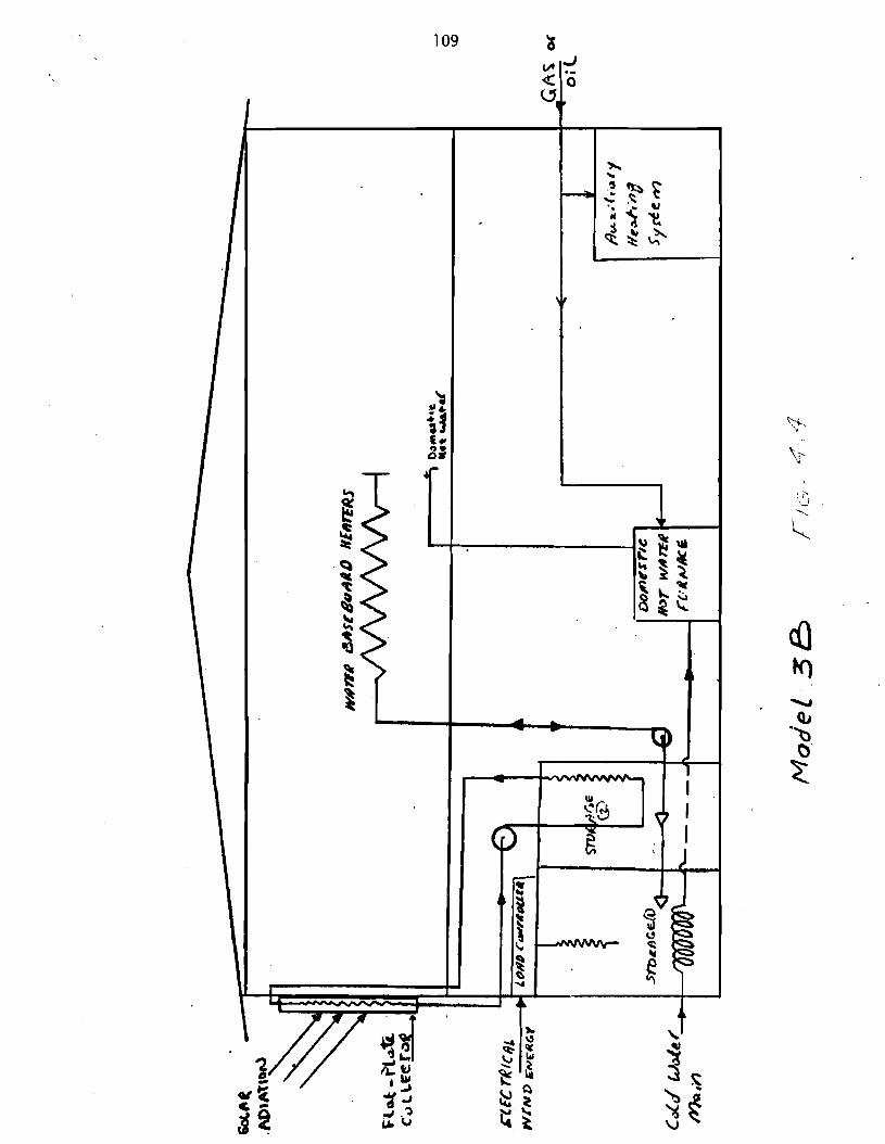

C. D i g i t a l Computer A n a l y t i c a l Models
Because o f t he v a r i e t y o f models t e s t e d and t h e number o f d i f f e r e n t
component c o n f i g u r a t i o n s t h e computer models i nc ludes t h e f o l l o w i n g
program and sub-programs: 1 ) a main program which s p e c i f i e s t h e model,
t h e system c o n f i g u r a t i o n , and t h e i n i t i a l c o n d i t i o n s o f t he v a r i o u s
components. Also, t he program combines t h e o t h e r sub-programs t o determine
t h e system performance (F ig . 4.5) , 2) a da ta sub-program which i nc ludes
t h e weather and s o l a r da ta f o r a g i ven s i t e , 3 ) a wind sub-program t h a t
c a l c u l a t e s t h e windpower a v a i l a b l e , 4) a s o l a r sub-program t h a t c a l c u l a t e s
t h e usefu l s o l a r energy a v a i l a b l e t o t h e house, 5 ) a l oad sub-program which
c a l c u l a t e s t h e house hea t i ng load, 6) a heat exchanger sub-program which
c a l c u l a t e s t h e energy d e l i v e r e d by t h e baseboard heaters, and 7) a ho t
water sub- rou t ine t h a t determines t h e energy d e l i v e r e d by t h e system i n
a form o f domest ic h o t water. The use of a s p e c i f i c sub-program depends
on t he system c o n f i g u r a t i o n of t h e model tes ted .
D. System Performance and Anal t y i c a l Resu l t s
A summary o f t h e most impo r tan t a n a l y t i c a l r e s u l t s f o r t h e v a r i o u s
models p r e v i o u s l y d iscussed fo l l ows . The r e s u l t s a r e based on m a i n t a i n i n g
t h e house i n s i d e temperature a t 68OF. A l l systems a r e t e s t e d f o r bo th t h e
average and model homes by v a r y i n g key system parameters such as:
1 ) wind genera to r b lade d iarneter
2 ) wind generator tower h e i g h t
3 ) water s torage tank s i z e
4 ) t h e hea t de1iver.y system s i z e
5 ) s o l a r c o l l e c t o r s i z e
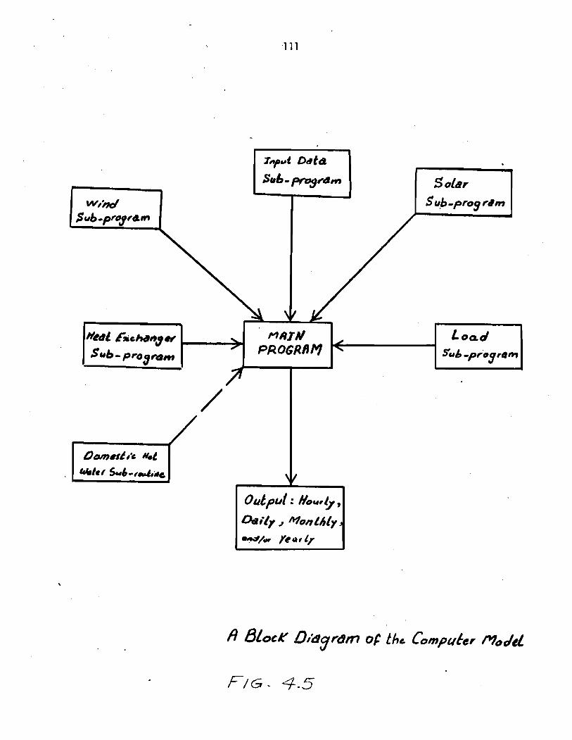
Sub - p m g t ~ m
Table 4.1 represents a monthly sumnary of the heat ing load o f both
the average and model halies based on the weather data fro111 art ford,
Conn. F igu re 4.6 represents t y p i c a l monthly values o f the "average"
home energy requirements and the i n p u t o f the wind and s o l a r systems.
The rep resen ta t i ve windpower output shown i n the f i g u r e i s based on a
32.5 f o o t blade diameter wind generator placed on an 80 f o o t h igh tower.
The s o l a r energy i n p u t i s g iven f o r a 200 square f o o t f l a t p l a t e s o l a r
c o l l e c t o r , mounted v e r t i c a l l y on the south wa l l o f the house. Due t o
the i n t e r a c t i o n between the system components, and o ther losses, the
amount o f s o l a r and wind energy the system d e l i v e r s t o the house i s
l ess than the energy i npu ts shown i n the f i g u r e . To determine the exact
amount o f use fu l energy de l i ve red by the system an hour-by-hour ana lys i s
i s performed using the a n a l y t i c a l model described prev ious ly .
To determine and compare t h e performance o f the p rev ious l y described
models, a parameter (Qaux/Qtotal ) i s defined as the r a t i o o f t he energy
de l i ve red t o the house from an a u x i l i a r y source t o the t o t a l house heat ing
energy requirements. Throughout the past year, a l a rge number o f
canputer runs f o r the Hart ford wind data and Blue H i l l s , Mass. s o l a r
data were performed. Th is parameter serves t o measure the energy performance
of the var ious systems, and as a major i n p u t t o f u t u r e system economic
studies. F igure 4.7 shows performance f o r the wind generator system
w i thou t storage (Yodel 1) as a func t i on o f wind generator blade diameter
and tower he ight ( lower 1 ines of each band represent 100 ft. tower he ights ) .
The performance o f t h e windpower heat ing system w i t h water thermal s torage i s
summarized f o r vary ing storage s izes and b lade diameters i n Figures 4.8
and 4.9.

Month Model House* (No Basement)
SEPTEMBER 308.7
OCTOBER 826.1
NOVEMBER 184.1 .1
DECEMBER 2295.5
JANUARY 301 8.6
FEBRUARY 2265.9
MARCH 2172.8
APRIL 1481.8
MAY
To ta l l oad f o r 1 5028.4 kWhr Heat ing Season
Average House* (SH-1) (Model w i t h Basement)
721.6
1850.6
3503.8
4829.3
6272.1
4746.1
4581.6
3186.2
1822.2
31 91 3. kWhr
Table 4.1 - Res iden t i a l Heat ing Requirements ( f o r 6600 Degree Day C l imate)
* These numbers m igh t be changed s l i g h t l y when t h e f i n a l house d e s c r i p t i o n i s added t o t he program.
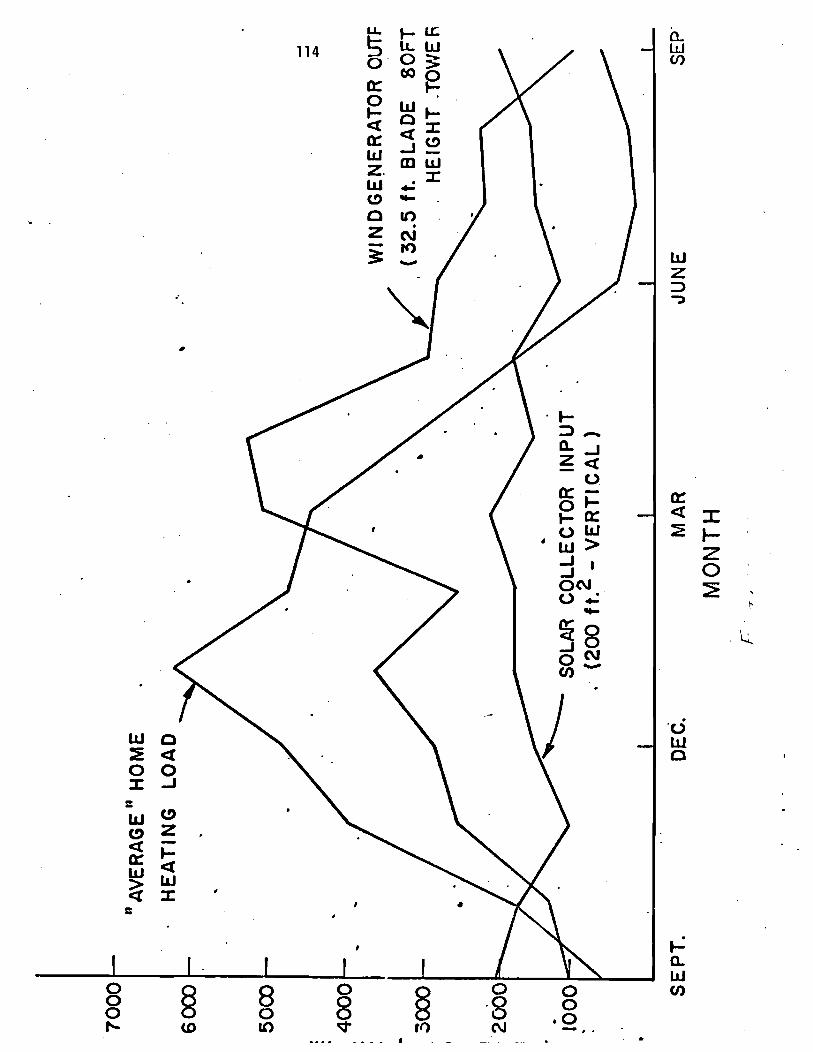
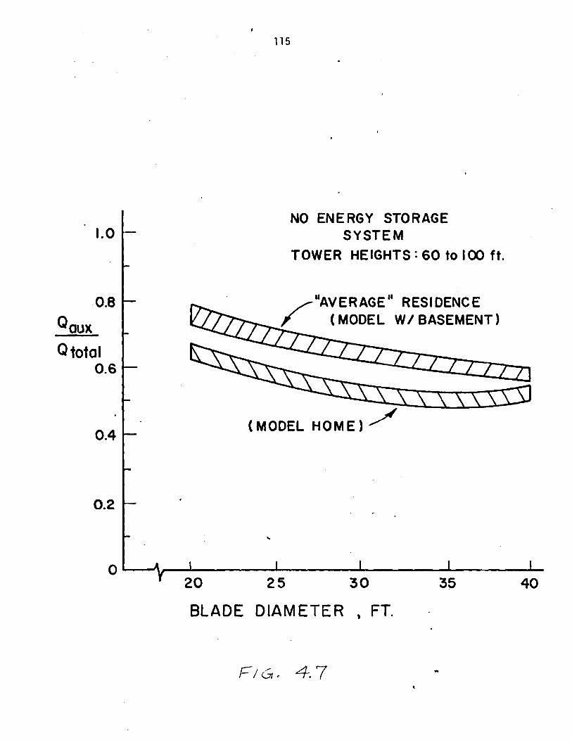
Q total 0.6
NO ENERGY STORAGE SYSTEM
TOWER HEIGHTS : 60 to I 0 0 ft.
"AVERAGE" RESIDENCE
(MODEL HOME) f
BLADE DIAMETER , FT.

The model l ing o f the combined wind and s o l a r heating system obviously
opens up the possi b i 1 i t y o f vary ing more system parameters, thus i t takes
more graphs t o show t h i s system's performance. Figures 4.10 t o 4.17
summarize a ser ies of runs f o r t h i s system. Figure 4.10 g ives r e s u l t s
f o r th ree house heat ing loads and vary ing c o l l e c t o r s ize , w i t h the
system a l s o supply ing 50 ga l lons o f hot water per day. F igure 4.11
shows the e f f e c t o f storage s i ze and blade diameter on system performance.
Figures 4.12 t o 4.14 present r e s u l t s f o r 3 d i f f e r e n t tower he ights vary ing
blade diameter and c o l l e c t o r area. Figures 4.15 t o 4.17 represent another
way o f showing these r e s u l t s .
The two tank storage system (Model 3B0 performance i s shown i n
Figures 4.18 t o 4.20. F igure 4.18 a l s o shows the performance o f so lar -on ly
and wind-only heat ing systems. From these se r ies o f a n a l y t i c a l runs
i t i s apparent t h a t the added cost o f the two tank system i s n o t
j u s t i f i e d by a l a r g e corresponding increase i n system performance.
With the increased a v a i l a b i l i t y o f more wind and s o l a r data a t the
end o f the 1975-76 heat ing season, i t i s an t i c ipa ted t h a t a se r ies o f
a n a l y t i c a l runs using t h i s new data w i l l be c a r r i e d out.
D. The Systems Economics Model
A d e t a i l e d cos t ana lys i s of the var ious systems under cons idera t ion
i s p resen t l y i n progress. This model inc ludes a d e t a i l e d c o s t ana lys is
(present and fu tu re p r i c e s ) of a l l the system component and i n s t a l l a t i o n
costs. The t o t a l c o s t o f the wind o r wind and so la r heat ing systems w i l l
i nc lude t h e a c q u i s i t i o n costs of a l l systems components, and the cost o f
operat ion and maintenance. I t i s planned t o opt imize system cost , vary ing

Qaux Q total
0.6
TOWER HEIGHT t 8 0 FT.
BLADE DIAMETER = 32.5 FT.
. .
'AVERAGE" HOME
MODEL HOME
(NO BASEMENT)
STORAGE S I Z E , GALLONS '

1 .o
0.8
Q aux total
0.6
0.4
0.2
0
T O W E R HEIGHTS =60to100 ft. STORAGE SIZE = 2000 GAL.
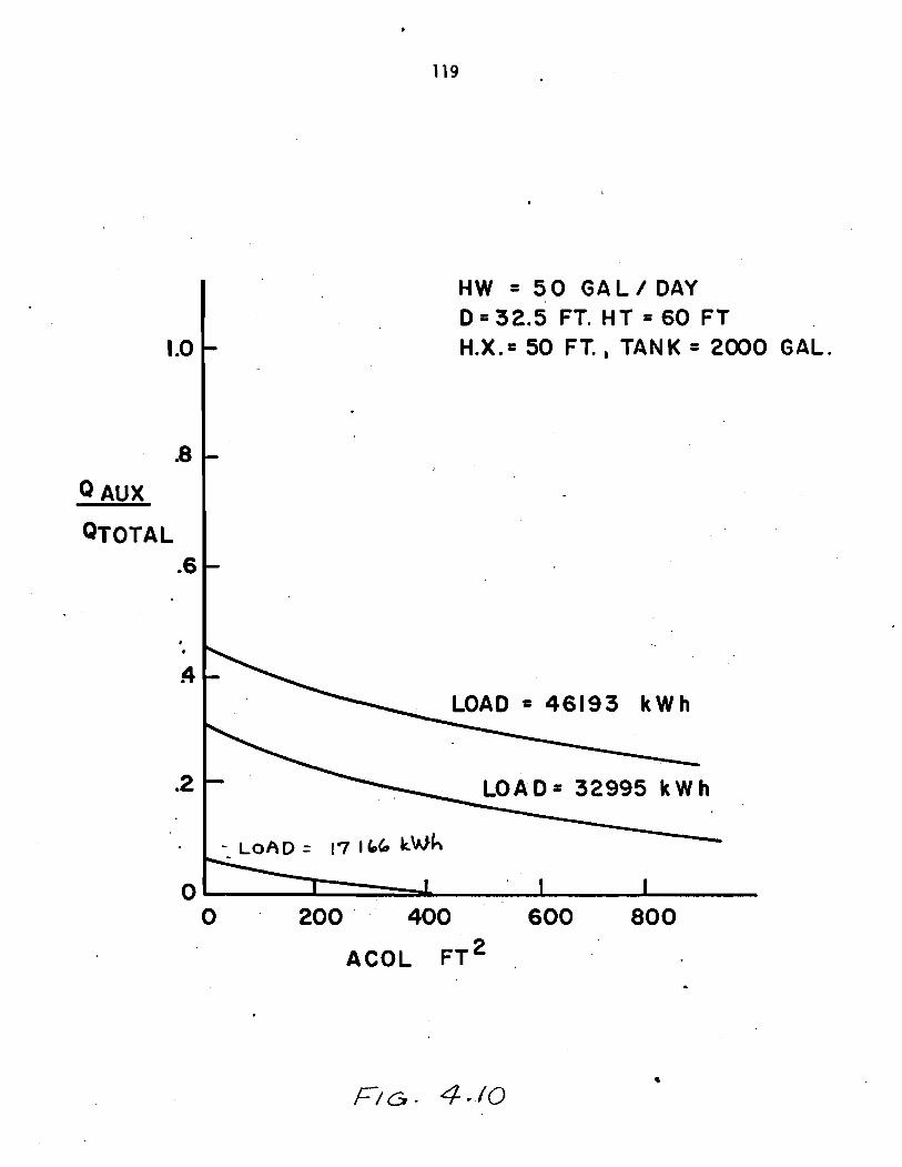
HW = 5 0 GAL/DAY D.32.5 FT. HT = 6 0 FT H.X.= 50 FT., TANK = 2000 GAL. 1.0
.8
AUX
QTOTAL .6
-
-
-
LOAD = 46193 k w h
LOAD= 32995 k w h
17 166 kwh
0 -; I I 1

"AVERAGE " HOUSE
TOWER HEIGHT. s 80 FT. ACOL = 200 F T . ~
WIND S SOLAR
STORAGE S I Z E , GALLONS

Q TOTAL .6
'AVERAGE " HOUSE
H T = 40 FT STORAGE = 2 0 0 0 GAL.
20 25 3 0 . 35 40
BLADE DIAMETE R , FT.

'AVERAGE" HOUSE HT = 60 FT. STORAGE 2 0 0 0
BLADE DIAMETER , FT
-1
.8
QAUX.
TOTAL -6
4
.2
7
-
-
-
- ACOL
200 FT2 4 4 0 0 F T ~ - - 600 F T ~
I I I I I
20 25 30 35 40
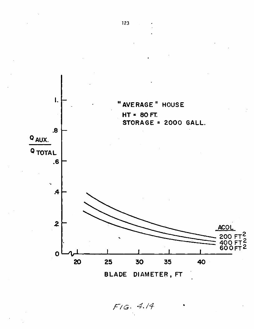
.8 AUX.
TOTA L .6
20 25 30 35 40
BLADE DIAMETER, FT

Q TOTAL .6
H.X. = 5 0 FT.
TANK = 2 0 0 0 GAL. ACOL = 2 0 0 F T . ~
- -- -
40 FT. 60 FT. 80 FT.
BLADE DIAMETER - FT.
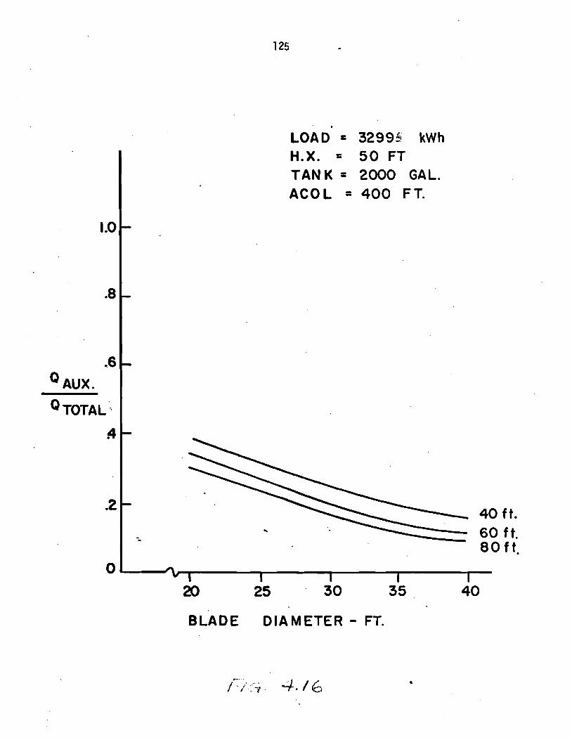
. LOAD = 32995 kwh H.X. = 5 0 FT TAN K = 2000 GAL. ACOL = 4 0 0 FT.
TOTAL '.,
4
BLADE DIAMETER - FT.

1 .o
.8
Q~~~ 06
TOTAL,
.4
.2
0
LOAD = 32995 kwh M.X. = 5 0 TANK = 2000 G A L . ACOL = 600 FT.
BLADE DIAMETER - FT.
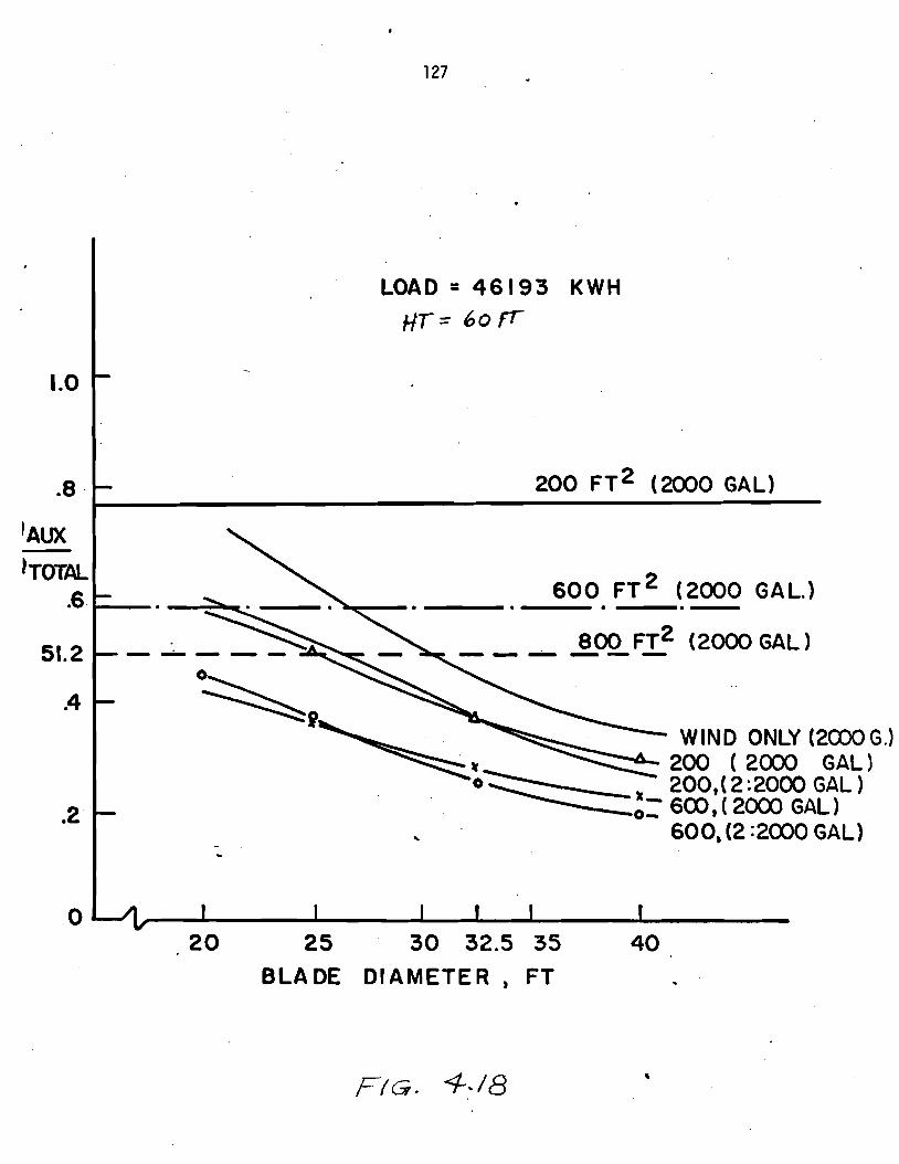
LOAD = 46193 K W H Hr= 6 0 f '
600 FT2 (2000 GAL. )
--- 800 F T ~ (2000 G A L ) ------
W I N D ONLY (2C00G.l 200 ( 2000 GAL 1 200,( 2 :2000 GAL ) 600, ( 2000 GAL)
4 600, (2 :2000 GAL)
BLADE DIAMETER, FT
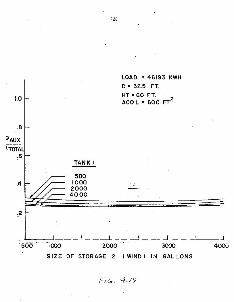
LOAD = 46193 KWH
D = 32.5 FT.
HT.60 FT. ACO L = 6 0 0 FT'
1.0
.8 . -
P~~~ ).TOTAL
.6
S I Z E OF STORAGE 2 ( W I N D ) I N GALLONS
-
- TANK I
- *.
--
;2-- -- - -
I I I I 1 I 1 ' - - - - . - .
loo0 2000 3000 4000

LOAD = 46193 K W H H T = 60 FT.
1.0
-8
'AM. - TOTAL
.6
D = 32.5FT. ACOL = 600 FT
.
. n
.
TANK 2
SIZE O F STORAGE ( S O L A R ) GALLONS

t h e impor tan t parameters t h a t a f f e c t o v e r a l l perfornlat~cc!.
2. EXPERIMENTAL SYSTEM
Under t h i s t ask o f t he work, t he thermal systems group has designed
and purchased a l l t he components necessary f o r t h e s i m u l a t i o n o f systems
1-3 i n St{-1. Previous q u a r t e r l y r e p o r t s have d e a l t w i t h t h e d e t a i l s o f
t h e exper imenta l system and w i l l n o t be repeated here. Dur ing t h e
summer o f 1976, a complete t e c h n i c a l r e p o r t d e s c r i b i n g t h e background
and f i n a l d e t a i l s o f t h e exper imenta l system w i l l be completed.
A t t h e p resent t ime, due t o t h e s h i f t i n g o f a v a i l a b l e t e c h n i c i a n s
t o o t h e r phases of t he p r o j e c t , t h e thermal subsystems (such as s o l a r
c o l l e c t o r s , s torage tanks, baseboard heaters , e t c . ) have n o t been
comple te ly i n s t a l l e d (and tes ted ) i n SH-1. However, a l l t h e necessary
equipment and p r e l i m i n a r y i ns t rumen ta t i on has been ob ta ined and i s
expected t o be i n o p e r a t i o n ( f o r exper imenta l t e s t i n g ) by June o f 1976.

UNNERSrrY OF MASSACHUSETTS/AMHERST ENERGY ALTERNATIVES PROGRAM
UNIVERSITY OF MASSACHUSETTS/AMHERST
ENERGY ALTERNATIVES PROGRAM
Pre l im ina ry Report
WIND DATA COLLECTION AND ANALYSIS
WIND FURNACE PROJECT
by
Frank C. Kaminsky
U.Mass. Wind Furnace
Energy A1 t e r n a t i v e s Program
U n i v e r s i t y o f Massachusetts
Amherst, frlassachusetts 01002
TR76/8
Appendix X

Wind Data C o l l e c t i o n and Ana l ys i s
The o v e r a l l o b j e c t i v e o f t h i s p o r t i o n o f t h e research e f f o r t i s
t h e development o f s t a t i s t i c a l models and computer so f twa re t h a t can
be used i n e s t i m a t i n g t h e p r o d u c t i v i t y o f a l t e r n a t i v e t ypes of w ind-
d r i v e n genera to rs proposed f o r a g i v e n l o c a t i o n . These models and
computer programs a r e be ing developed and t e s t e d u s i n g wind da ta f rom
the New England area and des ign da ta f r om seve ra l sources: The UMass
w ind -d r i ven gene ra to r s be ing ' cons t ruc ted and proposed as p a r t o f t h e
t o t a l r esea rch e f f o r t i n t h e development o f a wind fu rnace ; a l t e r n a t i v e
w ind -d r i ven genera to rs be ing cons t ruc ted and proposed by NASA; and
commerc ia l l y a v a i l a b l e gene ra t i ng systems f rom D u n l i t e , A u s t r a l i a ,
E l e c k t r o , Sw i t ze r l and and Aero Power, U.S.A. The work i n t h i s p o r t i o n
of t h e r esea rch e f f o r t i s p rog ress i ng on schedule and i s summarized
below i n two p a r t s . The f i r s t desc r i bes t h e d a t a c o l l e c t i o n s i t e s
t h a t have been e s t a b l i s h e d and t h e second desc r i bes t h e e f f o r t t h a t
has been d i r e c t e d toward t h e development o f s t a t i s t i c a l models and
computer so f tware .
P a r t I : Data C o l l e c t i o n S i t e s
Us ing equipment funds f rom t h e wind f u rnace g r a n t and a d d i t i o n a l
funds f rom o t h e r sources, f o u r da ta c o l l e c t i o n s i t e s have been e s t a b l i s h e d
i n t h e v i c i n i t y o f t h e U n i v e r s i t y o f !~~assachuset ts /Amhers t . These s i t e s
have been o p e r a t i n g c o n t i n u o u s l y s i n c e tF,c Summer of 1975 and w i l l p ro -
v i d e h o u r l y wind speed da ta t h a t serves as i n p u t t o computer s i m u l a t i o n
programs f o r e v a l u a t i n g t h e performance of t h e w i r~ r l furnace. These
s i t e s a r e l o c a t e d i n t h e towns of Leyden, N o r t h f i e l d , Shelburne and

Amherst, Massachusetts. Except f o r t h e Arnherst s i t e , cont inuous c h a r t -
paper reco rd inq systems have been i n s t a l l e d w i t h anemometer amps l oca ted
on towers and/or t e l e s c o p i c masts. A t t he Amherst s i t e , average wind
speed i s recorded a t ha l f - hou r i n t e r v a l s us ing a t ransmiss ion l i n e and
a mechanical paper punch. The r e s u l t i s a paper tape t h a t can be i n p u t
t o t h e t i m e shar ing system a t t h e U n i v e r s i t y . Since t h e anemometer cups
f o r t h i s system a re l oca ted a t t h e s i t e o f t h e home which i s being
cons t ruc ted as p a r t o f t h i s research e f f o r t , t h i s i n p u t w i l l p rov ide a
means o f eva lua t i ng and comparing the s imulated performance o f t h e wind
furnace t o t h e ac tua l performance.
Four o the r da ta s i t e s have been es tab l ished through a coopera t ive
e f f o r t between t h e research team and p r i v a t e i n d i v i d u a l s a l s o concerned
w i t h t h e development o f windpower systems. These i n d i v i d u a l s , Mr. R. B laze j ,
Grassy Brook V i l l a g e , Newfane, Vermont; Mr. D. Lawrence, Barnstable Harbor,
Barnstable, Massachusetts; M r . F. Harvey, M t . Equinox, Sky L i n e Dr ive ,
Vermont; and M r . G. Leary, Holyoke Gas and E l e c t r i c , have prov ided funds
and, w i t h ass is tance from t h e research team a t t h e U n i v e r s i t y o f Massachusetts,
have es tab l i shed da ta c o l l e c t i o n s i t e s . These s i t e s have been ope ra t i ng
con t i nuous l y s ince the F a l l of 1975 and w i l l p rov ide a d d i t i o n a l data f o r
eva lua t i ng t h e performance of t h e wind furnace.
I n a d d i t i o n t o t h e e i g h t s i t e s mentioned above, a d d i t i o n a l data has
been secured through t h e gene ros i t y of Brookhaven Nat iona l Labs, Long
Is land, New York. Th is data, h o u r l y wind speed taken s imul taneously a t
s i x d i f f e r e n t he igh ts (from 37 ft. t o 400 f t . ) f o r two years, w i l l p rov ide
the bas i s f o r severa l s t a t i s t i c a l s tud ies t h a t a r e being conducted.
Through the e f f o r t of severa l undergraduate s tudents a t UMass, t he
data f rom a l l s i t e s i s being analyzed on a month ly basis . A s o l i d data

base w i l l be a v a i l a b l e , e v e n t u a l l y , t o eva lua te t he performance o f
a l t e r n a t i v e designs f o r t he wind furnace i n d i f f e r e n t con tex ts , namely,
h i l l t o p l o c a t i o n s , coas ta l areas and v a l l e y l o c a t i o n .
6
P a r t 11: S t a t i s t i c a l Models and Computer Sof tware
Several computer programs have been.developed t o a s s i s t i n t h e
a n a l y s i s o f wind data. A l though these programs w i l l be used p r i m a r i l y
i n t h e e v a l u a t i o n o f w ind-d r i ven genera to rs under c o n s t r u c t i o n and be ing
proposed by researchers a t LlMass/Amherst, every a t tempt has been made
t o make a l l computer programs s u f f i c i e n t l y genera l f o r widespread use.
Since many of t h e computer programs a r e leng thy , t hey w i l l n o t be i n -
c luded as p a r t of t h i s progress r e p o r t . Only a d e s c r i p t i o n o f t h e p r o -
gram w i l l be prov ided. A1 1 programs have been w r i t t e n i n t h e F o r t r a n
language and a r e c u r r e n t l y be ing processed us ing t he Cont ro l Data Cyber
70-4 a t IIMass/Amherst. The au tomat ic p l o t t e r assoc ia ted w i t h t h i s
system i s used e x t e n s i v e l y t o save t ime and e f f o r t . Each computer
program i s descr ibed b r i e f l y be1 ow.
Program I
This program produces a v e l o c i t y - d u r a t i o n curve f o r i n p u t da ta
i n t h e form of h o u r l y wind speed o r i n t he form o f a h is togram o f h o u r l y
wind speed.
Program I1
T h i s program produces bo th a v e l o c i t y - d u r a t i o n curve and a power-
d u r a t i o n curve f o r e i t h e r h o u r l y wind speed da ta o r a h is togram o f h o u r l y
wind speed data. The user of t h i s program s p e c i f i c s t h e power ou tpu t
curve o f t h e w ind-d r i ven genera to r under c o n s i d e r a t i o n i n e i t h e r a f u n c t i o n a l
form o r as a s e r i e s of p iecewise 1 itnear approx imat ion.
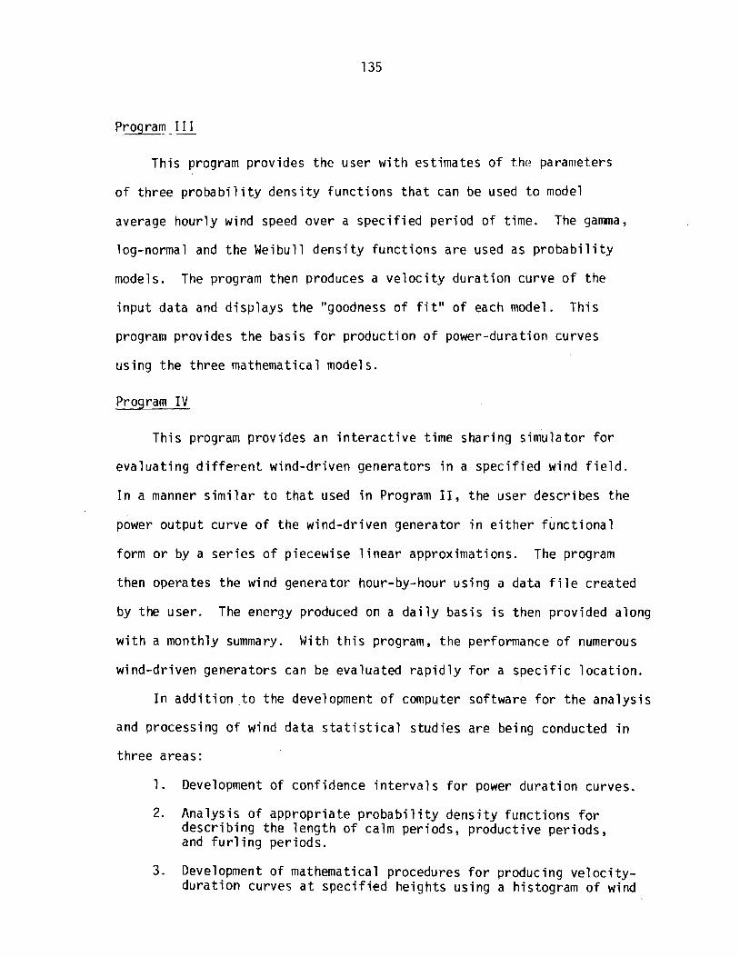
Program 11 I
This program provides the user w i t h est imates o f t he parameters
o f th ree p r o b a b i l i t y dens i t y func t ions t h a t can be used t o model
average hour ly wind speed over a spec i f i ed per iod o f time. The gamma,
log-normal and the Weibull dens i t y funct ions are used as p r o b a b i l i t y
models. The program then produces a v e l o c i t y du ra t ion curve o f the
inpu t data and d isp lays the "goodness o f f i t " o f each model. This
program provides the basis f o r product ion o f power-duration curves
using the three mathematical models.
Program I V
This program provides an i n t e r a c t i v e t ime shar ing s imulator f o r
eva luat ing d i f f e r e n t wind-driven generators i n a spec i f i ed wind f i e l d
I n a manner s i m i l a r t o t h a t used i n Program 11, the user describes the
power output curve o f the wind-driven generator i n e i t h e r func t iona l
form o r by a se r ies of piecewise l i n e a r approximations. The program
then operates the wind generator hour-by-hour using a data f i l e created
by the user. The energy produced on a d a i l y basis i s then provided along
w i t h a monthly summary. With t h i s program, the performance of numerous
wind-driven generators can be evaluated r a p i d l y fo r a spec i f i c l oca t ion .
I n a d d i t i o n . t o the development of computer software for the ana lys is
and processing of wind data s t a t i s t i c a l s tud ies are being conducted i n
three areas:
1. Development o f confidence i n t e r v a l s f o r power du ra t ion curves.
2. Analysis o f appropr ia te p r o b a b i l i t y dens i t y func t ions for descr ib ing the leng th of calm periods, product ive per iods, and f u r l i n g per iods.
3 . Development of mathematical procedures f o r producing v e l o c i t y - du ra t ion curves a t spec i f ied heights using a histogram of wind

data t h a t i s mixed. Mixed data occurs where a p o r t i o n o f t h e f requencies were recorded a t one he ight and another a t a second he ight , e t c .
A paper desc r ib ing the r e s u l t s obtained i n t h e t h i r d area described
above i s c u r r e n t l y i n process and w i l l be a v a i l a b l e s h o r t l y . The f i r s t
two areas described above a re under examination and r e s u l t s w i l l be
described as they become a v a i l a b l e .


UNNWITY OF MASSACr:;JS€llS/AMHER!X FNFRCV Al TFRNATNFC DEWTaAM
UNIVERSITY OF MASSACHUSETTS/AMHERST
ENERGY ALTERNATIVES PROGRAM
DYNAMICS OF NEW ENGLAND WIND FURNACE
by
M e r i t P . Wh i te
U.Mass. Wind Furnace
Energy A l t e r n a t i v e s Program
U n i v e r s i t y of Massachuset ts
Amherst, Massachuset ts 01 002
TR/76/9
Appendix X I


DYIUAMICS OF NEW ENGLANO WIND FIJKNACT
The f requencies and shapes o f t h e lower modes o f v i t ) , - a t i on o f
t he s t r u c t u r e and genera to r system have been c a l c u l a t e d . The p r i n c i p a l
dynamic loads have been analyzed and t h e i r i n t e r a c t i o n s w i t h t h e
v i b r a t i o n modes es t imated . The r e s u l t can be represented d i a g r a m a t i c a l l y
as a m a t r i x o f columns (modes of response) and rows ( l o a d i n g s ) .
General remarks
The e x t e n t t o which a p a r t i c u l a r mode o f v i b r a t i o n w i l l be e x c i t e d
by a p a r t i c u l a r l o a d i n g system depends p r i m a r i l y on t h e f o l l o w i n g
f a c t o r s :
1 Load magnitude
2. Degree o f coup l i ng between t h e e x c i t i n g mechanism and the
modal response. B a s i c a l l y , t h e e x c i t i n g f o r ce must be capable
o f do ing p o s i t i v e work d u r i n g a c y c l e o f mot ion. For example,
an e x t e r n a l f o r ce a c t i n g on a p o i n t o f t he s t r u c t u r e which has
a component o f mot ion p a r a l l e l t o t h e f o r c e does work and can
add energy t o t h e system w h i l e t h e system moves.
3 . Resonance: i n t h e case of a p e r i o d i c f o r ce t h e r e l a t i o n
between i t s frequency and t h a t of t h e modal response i s impor tan t ,
t h e c l o s e r t h e agreement t h e g r e a t e r i s t h e r a t e of do ing work on
t h e system.
4. System damping o r t he a b i l i t y t o d i s s i p a t e v i b r a t i o n a l energy
compared t o the r a t e a t which ene l yy i s supp l ied . A s teady s t a t e
cons tan t amp l i tude c o n d i t i o n i s reached when t h e two r a t e s a re
equal - work done p e r u n i t t ime equals mect:anical energy l o s t p e r
u n i t t ime.

The s t r u c t u r a l system o f t h e Windpower Furnace as c u r r e n t l y
designed does n o t c o n t a i n any s i g n i f i c a n t damping o r energy d i s s i p a t i n g
c a p a b i l i t y . I f i t t u r n s o u t t o be necessary, such mechanisms (damping
dev ices) can be i n s t a l l e d i n app rop r i a te l o c a t i o n s . T h i s should be
avoided i f p o s s i b l e because o f cos t s o f such u n i t s and a l s o the
necess i t y o f m a i n t a i n i n g them over t h e l i f e o f t h e system. A b e t t e r
s o l u t i o n f o r undes i rab le v i b r a t i o n s i s t o avo id resonances between
load ings and system v i b r a t i o n s , perhaps by changing s t i f f n e s s e s o r
weights o f components.
Modes o f V i b r a t i o n Consi --- dered
1. V e r t i c a l d isp lacement : The f o o t o f t h e 10" s t e e l p i p e tower
ma in ta i ns c o n t a c t w i t h i t s base suppor t due t o t h e we igh t o f t h e whole
system combined w i t h t he v e r t i c a l corr~ponent of t h e 3000- lb f o r c e i n
each o f t h e f o u r s t e e l - r o p e guys. The s t e e l p i p e and t h e genera to r
u n i t have a combined weight o f 4900 I b s . Thus t h e t o t a l base compression
i s about 16,000 I b s and t h i s i s t h e maximum va lue o f a v e r t i c a l dynamic
o s c i l l a t i o n f o r c e t h a t w i l l n o t cause u p l i f t . A more severe v i b r a t i o n
w i l l produce u p l i f t and t he r e s u l t w i l l be a l a r g e energy d i s s i p a t i o n
due t o repeated impacts a t t h e base. A v e r t i c a l v i b r a t i o n mode can be
produced by a v e r t i c a l dynamic l oad ing , f o r example due t o b lade unbalance.
The extreme case occurs i f a b lade i s l o s t d u r i n g r o t a t i o n . The
c e n t r i f u g a l f o r c e i n t h a t s i t u a t i o n i s
2 F = W r (,) / g
where W = b lade weight , r = d i s t a n c e of i t s c e n t e r o f g r a v i t y f rom t h e
s p i n a x i s , (,J t h e angu la r v e l o c i t y i n rad ians lsecond, and g = g r a v i t y
a c c e l e r a t i o n . A t t h e maximum expected RPM, W = 7 7 I b , r = 4 ' , u = 17.5
and g = 32.2. Then,
F = 3000 l b
F has a p e r i o d T = 0.36 sec. A t lower speeds t h e dynamic f o r ce i s
reduced and t h e p e r i o d lengthened.
2A-2B. A x i a l (horizonta1)displacement o f t h e genera to r u n i t
combined w i t h p i t c h i n g about a h o r i z o n t a l t r ansve rse a x i s : T h i s mode
causes f l e x u r e o f t he suppo r t i ng p i p e and changes o f l e n g t h o f t h e guys.
Two modes have been c a l c u l a t e d : t h e lower i s p r i m a r i l y t r a n s l a t i o n w i t h
smal l p i t c h i n g ang les and has a p e r i o d o f 0.7 second. The second i s
p r i m a r i l y p i t c h i n g w i t h sma l l t r a n s l a t i o n s and has a p e r i o d o f 0.05
seconds .
3A-3B. L a t e r a l t r a n s l a t i o n combined w i t h r o c k i n g about t h e
l o n g i t u d i n a l a x i s : There a r e two modes c a l c u l a t e d , t h e f i r s t i s p r i m a r i l y
t r a n s l a t i o n w i t h a p e r i o d of 0.7 seconds, t h e second i s p r i m a r i l y r o c k i n g
w i t h a p e r i o d o f 0.03 seconds.
4A-4B. T o r s i o n a l (abou t a v e r t i c a l a x i s c o i n c i d i n g w i t h t h e suppor t
a x i s ) : Two c o n d i t i o n s have been cons idered : i n t h e f i r s t , t he base o f
t h e suppo r t i ng p i p e i s n o t r e s t r a i n e d i n t o r s i o n and t h e o n l y t o r s i o n a l
r e s t r a i n t i n t h e system i s fu rn ished by t h e guys. T h i s mode has a p e r i o d
of 1.66 seconds. I f t h e base of t h e suppor t i s r e s t r a i n e d i n t o r s i o n t h e
p e r i o d becomes 0.12-0.15 seconds. I n each case, t h e gene ra to r u n i t i s
assumed t o be r i g i d l y f i x e d by a brake t o t h e suppo r t i ng mast. Of course,
d u r i n g o p e r a t i o n t h e genera to r u n i t i s n o t so r e s t r a i n e d and t h e r e i s no
t o r s i o n a l o r r o t a t i o n a l mode o f ,i b r a t i o n .
5. A i r f o i l f l e x u r e : Time dependent a i r f o i l l oads w i l l cause t h e
a i r f o i l t o d e f l e c t , m a i n l y i n i t s weakest d i r e c t i o e which i s r ough l y
p a r a l l e l t o t h e s p i n a x i s o f t h e system. Th i s i s an impo r tan t des ign

cons ide ra t i on s ince i t determines how much c learance between the a i r f o i 1
d i s c and the suppor t systc111 - s t e e l p ipe and guys - hac t o ho l e f t ,
f o r t h i s bending de fo rn~a t i on . The s ~ i ~ a l l e r t h e f l e x u r e al lowance o f the
a i r f o i l b lades t h e h igher can be the p o i n t o f attachment o f the guys
t o t h e suppor t ing p ipe . The h igher t h a t at tachment t h e s t i f f e r and
s t ronge r i s t h e system as a whole, which i s advantageous. The f l e x u r a l
f requency o f each blade i s est imated, f rom measurements on a s imp ly
supported blade, t o be about 3 - 4 cyc les pe r second when c a n t i l e v e r e d a t
the hub.
Dynamic Loads
1. Blade unbalance: D i f fe rences i n weight o r geometry o f
i n d i v i d u a l blades can g i v e r i s e t o unbalanced c e n t r i f u g a l f o r ces normal
t o t h e r o t a t i n g s h a f t a c t i n g a t t h e hub. Th i s fo rce v e c t o r r o t a t e s
w i t h t h e t u r n i n g s h a f t . Besides producing bending s t resses i n t h e
s h a f t t h i s f o r c e can a l s o i n i t i a t e o s c i l l a t i o n i n Modes 1, 2B, 3A, 3B,
4A ( o r 4B). The extreme case i s , o f course, t h a t i n which a b lade i s
l o s t .
2. Wind g r a d i e n t and tower shadow: Dur ing a r o t a t i o n each b lade
passes through a c y c l e o f d i f f e r e n t wind v e l o c i t i e s . The wind g rad ien t
r e s u l t s from t h e ground drag which normal ly r e s u l t s i n i nc reas ing wind
speeds w i t h e l e v a t i o n . Tower shadow i s due t o i n t e r f e r e n c e o f the
suppor t ing p i p e w i t h t he a i r f l o w . The r e s u l t i n g l i f t f o r c e on each b lade
i s a p e r i o d i c fo rce so t h a t t h e combined l oad ing due t o a l l t h r e e blades
acted on by t h e wind i s a p e r i o d i c fo rce more o r l e s s p a r a l l e l t o the s p i n
a x i s and a p e r i o d i c couple about a h o r i z o n t a l a x i s normal t o t h e s p i n
ax i s . Both have t h e same frequency, t h ree t imes t h e r o t a t i o n a l f requency
of t h e shaf t . The e f f e c t of t h i s l oad ing i s t o cause h o r i z o n t a l
o s c i l l a t i o n s p a r a l l e l t o t h e s p i n a x i s and angu la r o s c i l l a t i o n s
about a h o r i z o n t a l a x i s through t h e mass cen te r and normal t o t h e
s p i n a x i s .
3. Gusts and tu rbu lence : These g i v e r i s e t o non-per iod ic f o r ces
a c t i n g on t h e b lades more o r l e s s p a r a l l e l t o t h e s p i n a x i s . There
would a l s o be some l oad ing o f t h e genera to r u n i t . The blades and tower
have t o be designed f o r peak g u s t loads. There i s u n l i k e l y t o be any
p e r i o d i c response o f t h e system.
4. Gy roscop i c -Co r i o l i s Forces: These r e s u l t f rom simultaneous
r o t a t i o n s about two pe rpend i cu la r axes, i n t h i s case t h e s p i n LI o f
t h e sha f t , r o t o r , and b lade assembly on t h e one hand, c o i n c i d i n g w i t h
a r o t a t i o n n o f t he e n t i r e system about i t s v e r t i c a l a x i s , due t o a
change of wind d i r e c t i o n . For an corresponding t o 167 rpm and a
reasonable va lue o f i? , f o r example 1 rpm ( = 0.1 rad /sec) , t h e C o r i o l i s
a c c e l e r a t i o n a t t h e t i p o f a b lade i s sma l l , about 29. The gyroscop ic
coup le o f t he whole r o t o r , sha f t , e t c . i s
c = Io)n
where I i s t h e mass moment of i n e r t i a about t h e s h a f t a x i s .
For a l l p e r i o d i c l oad ings t h e pe r i ods o r ranges o f pe r i ods have
been c a l c u l a t e d . There has been no a t tempt t o p r e d i c t modal responses
caused by t h e expected loads s i nce t h e r e s u l t o f any such c a l c u l a t i o n i s
expected t o be h i g h l y undependable. When the system i s i n ope ra t i on ,
observa t ions w i l l i n d i c a t e which of t he modes a r e e x c i t e d and t o what
ex ten t . I f c u r a t i v e measures a r e needed, t hey w i l l be f a c i l i t a t e d by
knowing which of t h e dynamic l oad ings may be caus ing t h e t r o u b l e .
The f o l l o w i n g t a b l e shows ( h o r i z o n t a l l y ) t h e b.arious modes o f response
and ( v e r t i c a l l y ) t h e severa l dynamic l o a d i n g mechanisms - bo th w i t h t h e i r

p e r i o d s o r f r e q u e n c i e s . The squares w i t h + cor respond t o a p o s s i b l e
model e x c i t e m e n t by a p a r t i c u l a r l oad . An ++ i n d i c a t e s a p r o b a b l e
s t a t e o f e x c i t a t i o n .