MSÜ ABF - · PDF fileTitle: MSÜ ABF Author: Fotomekanik Created Date: 20180105124939Z
35011388 05/2009
3501
1388
.04
www.schneider-electric.com
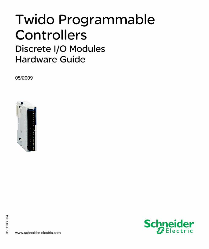
Twido Programmable ControllersDiscrete I/O ModulesHardware Guide
05/2009

Schneider Electric assumes no responsibility for any errors that may appear in this document. If you have any suggestions for improvements or amendments or have found errors in this publication, please notify us.
No part of this document may be reproduced in any form or by any means, electronic or mechanical, including photocopying, without express written permission of Schneider Electric.
All pertinent state, regional, and local safety regulations must be observed when installing and using this product. For reasons of safety and to help ensure compliance with documented system data, only the manufacturer should perform repairs to components.
When devices are used for applications with technical safety requirements, the relevant instructions must be followed.
Failure to use Schneider Electric software or approved software with our hardware products may result in injury, harm, or improper operating results.
Failure to observe this information can result in injury or equipment damage.
© 2009 Schneider Electric. All rights reserved.
2 35011388 05/2009

Table of Contents
Safety Information . . . . . . . . . . . . . . . . . . . . . . . . . . . . . . 5About the Book . . . . . . . . . . . . . . . . . . . . . . . . . . . . . . . . . 9
Chapter 1 Overview for Discrete I/O Modules . . . . . . . . . . . . . . . . . 11About Discrete I/O Modules . . . . . . . . . . . . . . . . . . . . . . . . . . . . . . . . . . . 12Main Features of the Discrete I/O Modules. . . . . . . . . . . . . . . . . . . . . . . . 14
Chapter 2 Installation. . . . . . . . . . . . . . . . . . . . . . . . . . . . . . . . . . . . . 152.1 Installation Overall Instructions . . . . . . . . . . . . . . . . . . . . . . . . . . . . . . . . . 16
Installation Guidelines . . . . . . . . . . . . . . . . . . . . . . . . . . . . . . . . . . . . . . . . 17Installation Preparation . . . . . . . . . . . . . . . . . . . . . . . . . . . . . . . . . . . . . . . 20Compact and Modular Bases Mounting Positions. . . . . . . . . . . . . . . . . . . 21Assembling an Expansion I/O module to a Base . . . . . . . . . . . . . . . . . . . 23Disassembling an Expansion I/O Module from a Base . . . . . . . . . . . . . . . 25Minimum Clearances for Bases and Expansion I/O Modules in a Control Panel . . . . . . . . . . . . . . . . . . . . . . . . . . . . . . . . . . . . . . . . . . . . . . . . . . . . . 26
2.2 Installation of Discrete I/O Modules. . . . . . . . . . . . . . . . . . . . . . . . . . . . . . 28Dimensions for Discrete I/O Modules . . . . . . . . . . . . . . . . . . . . . . . . . . . . 29How to Directly Mount a Discrete I/O Module on a Panel Surface . . . . . . 32How to Install and Remove a Discrete I/O Module from a DIN Rail . . . . . 34
Chapter 3 Description of Discrete I/O Modules . . . . . . . . . . . . . . . . 373.1 Discrete I/O Modules Description . . . . . . . . . . . . . . . . . . . . . . . . . . . . . . . 38
Overview of Discrete I/O Modules. . . . . . . . . . . . . . . . . . . . . . . . . . . . . . . 39Parts Description of Discrete I/O Modules . . . . . . . . . . . . . . . . . . . . . . . . 40
3.2 Wiring Rules and Recommendations for Discrete I/O Modules . . . . . . . . 42Wiring Rules and Recommendations for Discrete I/O Modules . . . . . . . . 42
3.3 Specifications and Wiring Diagrams for Discrete Input Modules. . . . . . . . 47General Specifications for the Discrete Input Modules . . . . . . . . . . . . . . . 48Electrical Specifications for the Discrete Input Modules . . . . . . . . . . . . . . 49Input Specifications for the Discrete Input Modules . . . . . . . . . . . . . . . . . 50Discrete Input Modules Wiring Diagrams . . . . . . . . . . . . . . . . . . . . . . . . . 53
35011388 05/2009 3
3.4 Specifications and Wiring Diagrams for Relay Output Modules . . . . . . . 59General Specifications for the Relay Output Modules . . . . . . . . . . . . . . . 60Electrical Specifications for the Relay Output Modules . . . . . . . . . . . . . . 61Output Specifications for the Relay Output Modules . . . . . . . . . . . . . . . . 62Relay Output Modules Wiring Diagrams . . . . . . . . . . . . . . . . . . . . . . . . . 64
3.5 Specifications and Wiring Diagrams for Transistor Output Modules . . . . 67General Specifications for the Transistor Output Modules . . . . . . . . . . . 68Electrical Specifications for the Transistor Output Modules. . . . . . . . . . . 69Output Specifications for the Transistor Output Modules . . . . . . . . . . . . 70Transistor Output Module Wiring Diagrams. . . . . . . . . . . . . . . . . . . . . . . 72
3.6 Specifications and Wiring Diagrams for Discrete Mixed I/O Modules . . . 77General Specifications for the Mixed I/O Modules. . . . . . . . . . . . . . . . . . 78Electrical Specifications for the Mixed I/O Modules. . . . . . . . . . . . . . . . . 79I/O Specifications for the Mixed I/O Modules. . . . . . . . . . . . . . . . . . . . . . 80Mixed I/O Module Wiring Diagrams . . . . . . . . . . . . . . . . . . . . . . . . . . . . . 83
Appendices . . . . . . . . . . . . . . . . . . . . . . . . . . . . . . . . . . . . . . . . . . . 87Appendix A The DIN Rail . . . . . . . . . . . . . . . . . . . . . . . . . . . . . . . . . . . . 89
The DIN Rail . . . . . . . . . . . . . . . . . . . . . . . . . . . . . . . . . . . . . . . . . . . . . . 89Appendix B IEC Symbols . . . . . . . . . . . . . . . . . . . . . . . . . . . . . . . . . . . . 91
Glossary of Symbols . . . . . . . . . . . . . . . . . . . . . . . . . . . . . . . . . . . . . . . . 91Appendix C Agency Compliance. . . . . . . . . . . . . . . . . . . . . . . . . . . . . . 93
Agency Requirements . . . . . . . . . . . . . . . . . . . . . . . . . . . . . . . . . . . . . . . 93
Glossary . . . . . . . . . . . . . . . . . . . . . . . . . . . . . . . . . . . . . . . . . . . 95Index . . . . . . . . . . . . . . . . . . . . . . . . . . . . . . . . . . . . . . . . . . . 103
4 35011388 05/2009

§
Safety InformationImportant Information
NOTICE
Read these instructions carefully, and look at the equipment to become familiar with the device before trying to install, operate, or maintain it. The following special messages may appear throughout this documentation or on the equipment to warn of potential hazards or to call attention to information that clarifies or simplifies a procedure.
35011388 05/2009 5

PLEASE NOTE
Electrical equipment should be installed, operated, serviced, and maintained only by qualified personnel. No responsibility is assumed by Schneider Electric for any consequences arising out of the use of this material.
General Warnings and Cautions
DANGERHAZARD OF ELECTRIC SHOCK, BURN OR EXPLOSION
Turn off all power before starting installation, removal, wiring, maintenance or inspection of the smart relay system.
Failure to follow these instructions will result in death or serious injury.
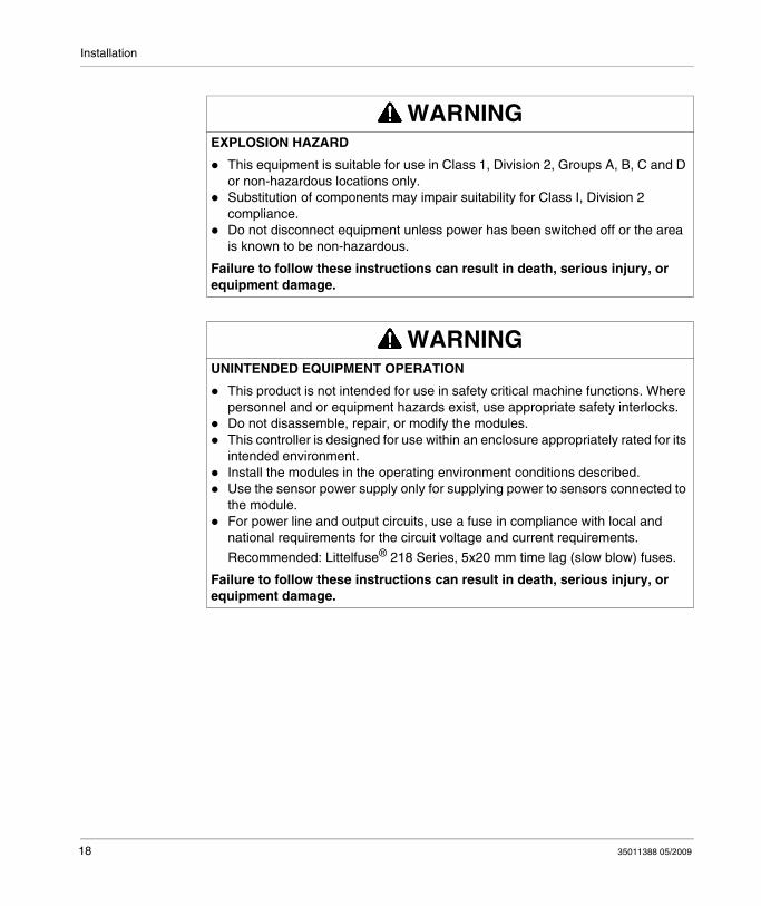
WARNINGEXPLOSION HAZARD
Substitution of components may impair suitability for Class I, Div 2 compliance.
Do not disconnect equipment unless power has been switched off or the area is known to be non-hazardous.
Failure to follow these instructions can result in death, serious injury, or equipment damage.
6 35011388 05/2009
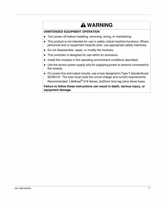
WARNINGUNINTENDED EQUIPMENT OPERATION
Turn power off before installing, removing, wiring, or maintaining.
This product is not intended for use in safety critical machine functions. Where personnel and or equipment hazards exist, use appropriate safety interlocks.
Do not disassemble, repair, or modify the modules.
This controller is designed for use within an enclosure.
Install the modules in the operating environment conditions described.
Use the sensor power supply only for supplying power to sensors connected to the module.
For power line and output circuits, use a fuse designed to Type T standards per IEC60127. The fuse must meet the circuit voltage and current requirements.
Recommended: Littelfuse® 218 Series, 5x20mm time lag (slow blow) fuses.
Failure to follow these instructions can result in death, serious injury, or equipment damage.
35011388 05/2009 7

8 35011388 05/2009

About the Book
At a Glance
Document Scope
This manual provides parts descriptions, specifications, wiring diagrams, installation, setup, and troubleshooting information for Twido Discrete I/O and AS-Interface modules.
Validity Note
The information in this manual is applicable only for Twido products. This documentation is valid for TwidoSuite Version 2.2.
User Comments
We welcome your comments about this document. You can reach us by e-mail at [email protected].
35011388 05/2009 9

10 35011388 05/2009
35011388 05/2009
1
Overview for Discrete I/O Modules
35011388 05/2009
Overview for Discrete I/O Modules
Introduction
This chapter provides an overview of the Discrete I/O modules, their maximum configurations, and their main functions.
What's in this Chapter?
This chapter contains the following topics:
Topic Page
About Discrete I/O Modules 12
Main Features of the Discrete I/O Modules 14
11
Overview for Discrete I/O Modules
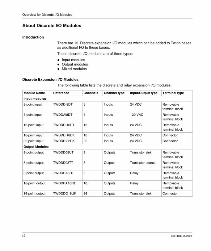
About Discrete I/O Modules
Introduction
There are 15 Discrete expansion I/O modules which can be added to Twido bases as additional I/O to these bases.
These discrete I/O modules are of three types:
Input modulesOutput modulesMixed modules
Discrete Expansion I/O Modules
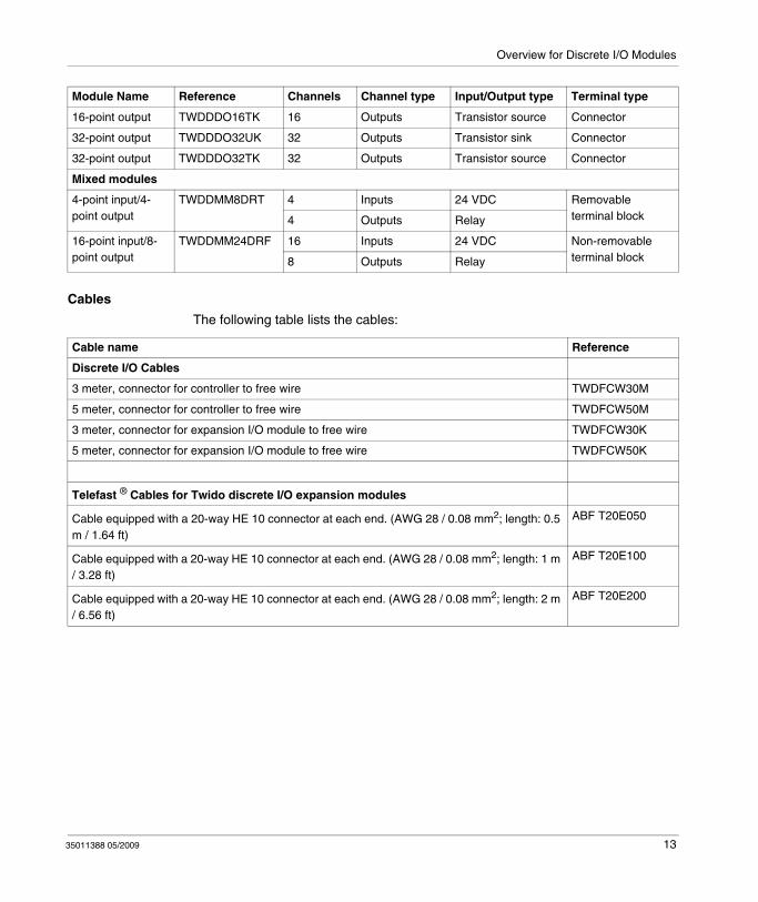
The following table lists the discrete and relay expansion I/O modules:
Module Name Reference Channels Channel type Input/Output type Terminal type
Input modules
8-point input TWDDDI8DT 8 Inputs 24 VDC Removable terminal block
8-point input TWDDAI8DT 8 Inputs 120 VAC Removable terminal block
16-point input TWDDDI16DT 16 Inputs 24 VDC Removable terminal block
16-point input TWDDDI16DK 16 Inputs 24 VDC Connector
32-point input TWDDDI32DK 32 Inputs 24 VDC Connector
Output Modules
8-point output TWDDD08UT 8 Outputs Transistor sink Removable terminal block
8-point output TWDDD08TT 8 Outputs Transistor source Removable terminal block
8-point output TWDDRA8RT 8 Outputs Relay Removable terminal block
16-point output TWDDRA16RT 16 Outputs Relay Removable terminal block
16-point output TWDDDO16UK 16 Outputs Transistor sink Connector
12 35011388 05/2009
Overview for Discrete I/O Modules
Cables
The following table lists the cables:
16-point output TWDDDO16TK 16 Outputs Transistor source Connector
32-point output TWDDDO32UK 32 Outputs Transistor sink Connector
32-point output TWDDDO32TK 32 Outputs Transistor source Connector
Mixed modules
4-point input/4-point output
TWDDMM8DRT 4 Inputs 24 VDC Removable terminal block4 Outputs Relay
16-point input/8-point output
TWDDMM24DRF 16 Inputs 24 VDC Non-removable terminal block8 Outputs Relay
Module Name Reference Channels Channel type Input/Output type Terminal type
Cable name Reference
Discrete I/O Cables
3 meter, connector for controller to free wire TWDFCW30M
5 meter, connector for controller to free wire TWDFCW50M
3 meter, connector for expansion I/O module to free wire TWDFCW30K
5 meter, connector for expansion I/O module to free wire TWDFCW50K
Telefast ® Cables for Twido discrete I/O expansion modules
Cable equipped with a 20-way HE 10 connector at each end. (AWG 28 / 0.08 mm2; length: 0.5 m / 1.64 ft)
ABF T20E050
Cable equipped with a 20-way HE 10 connector at each end. (AWG 28 / 0.08 mm2; length: 1 m / 3.28 ft)
ABF T20E100
Cable equipped with a 20-way HE 10 connector at each end. (AWG 28 / 0.08 mm2; length: 2 m / 6.56 ft)
ABF T20E200
35011388 05/2009 13
Overview for Discrete I/O Modules
Main Features of the Discrete I/O Modules
Introduction
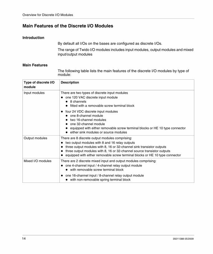
By default all I/Os on the bases are configured as discrete I/Os.
The range of Twido I/O modules includes input modules, output modules and mixed input/output modules
Main Features
The following table lists the main features of the discrete I/O modules by type of module:
Type of discrete I/O module
Description
Input modules There are two types of discrete input modulesone 120 VAC discrete input module
8 channelsfitted with a removable screw terminal block
four 24 VDC discrete input modulesone 8-channel moduletwo 16-channel modulesone 32-channel moduleequipped with either removable screw terminal blocks or HE 10 type connectoreither sink modules or source modules
Output modules There are 8 discrete output modules comprising:two output modules with 8 and 16 relay outputsthree output modules with 8, 16 or 32-channel sink transistor outputsthree output modules with 8, 16 or 32-channel source transistor outputsequipped with either removable screw terminal blocks or HE 10 type connector
Mixed I/O modules There are 2 discrete mixed input and output modules comprising:one 4-channel input / 4-channel relay output module
with removable screw terminal block
one 16-channel input / 8-channel relay output modulewith non-removable spring terminal block
14 35011388 05/2009

35011388 05/2009
2
Installation
35011388 05/2009
Installation
Introduction
This chapter provides installation overall instructions for installation preparation, installation and mounting instructions for the Twido discrete I/O modules, and how to connect the power supply.
What's in this Chapter?
This chapter contains the following sections:
Section Topic Page
2.1 Installation Overall Instructions 16
2.2 Installation of Discrete I/O Modules 28
15
Installation
2.1 Installation Overall Instructions
Introduction
This section provides information for installation preparation, how to assemble and disassemble discrete I/O modules, and minimum clearances for discrete I/O modules.
What's in this Section?
This section contains the following topics:
Topic Page
Installation Guidelines 17
Installation Preparation 20
Compact and Modular Bases Mounting Positions 21
Assembling an Expansion I/O module to a Base 23
Disassembling an Expansion I/O Module from a Base 25
Minimum Clearances for Bases and Expansion I/O Modules in a Control Panel 26
16 35011388 05/2009

Installation
Installation Guidelines
NOTICE
Electrical equipment should be serviced only by qualified personnel. No responsi-bility is assumed by Schneider Electric for any consequences arising out of the use of this material. This document is not intended as an instruction manual for untrained persons.
(c) 2008 Schneider Electric All Rights Reserved
Additional Information
Those responsible for the application, implementation or use of this product must ensure that the necessary design considerations have been incorporated into each application, completely adhering to applicable laws, performance and safety requirements, regulations, codes and standards.
General Warnings and Cautions
DANGERHAZARD OF ELECTRIC SHOCK, EXPLOSION OR ARC FLASH
Remove all power from all devices before inspecting, installing, removing, wiring, or servicing any inputs, outputs, or hardware.Connect the grounding wire to a proper ground.Always use a properly rated voltage sensing device to confirm power is off.Remove the terminal block before installing/removing the module from the rail, rack or enclosure. Terminal blocks must be connected or disconnected with sensor and pre-actuator voltage switched off.Replace and secure all covers or elements of the system and confirm that a proper ground connection exists before applying power to the unit.Use only the specified voltage when operating your Twido and associated products.
Failure to follow these instructions will result in death or serious injury.
35011388 05/2009 17
Installation
WARNINGEXPLOSION HAZARD
This equipment is suitable for use in Class 1, Division 2, Groups A, B, C and D or non-hazardous locations only.Substitution of components may impair suitability for Class I, Division 2 compliance.Do not disconnect equipment unless power has been switched off or the area is known to be non-hazardous.
Failure to follow these instructions can result in death, serious injury, or equipment damage.
WARNINGUNINTENDED EQUIPMENT OPERATION
This product is not intended for use in safety critical machine functions. Where personnel and or equipment hazards exist, use appropriate safety interlocks.Do not disassemble, repair, or modify the modules.This controller is designed for use within an enclosure appropriately rated for its intended environment.Install the modules in the operating environment conditions described.Use the sensor power supply only for supplying power to sensors connected to the module.For power line and output circuits, use a fuse in compliance with local and national requirements for the circuit voltage and current requirements.
Recommended: Littelfuse® 218 Series, 5x20 mm time lag (slow blow) fuses.
Failure to follow these instructions can result in death, serious injury, or equipment damage.
18 35011388 05/2009

Installation
1For additional information refer to NEMA ICS 1.1 (latest edition), "Safety Guidelines for the Application, Installation, and Maintenance of Solid State Control."
Before Starting
Before installing any of the products read the safety information at the beginning of this book.
NOTE: All options and expansion I/O modules are to assembled before installing the control system on a DIN rail, onto a mounting plate, or in a control panel. Remove the Twido System from a DIN rail, a mounting plate, or a control panel before disassembling the expansion I/O modules.
WARNINGLOSS OF CONTROL
The designer of any control scheme must consider the potential failure modes of control paths and, for certain critical control functions, provide a means to achieve a safe state during and after a path failure. Examples of critical control functions are emergency stop and overtravel stop.Separate or redundant control paths must be provided for critical control functions.System control paths may include communication links. Consideration must be given to the implications of unanticipated transmission delays or failures of the
link1.Each implementation of the Twido Programmable Controller must be individually and thoroughly tested for proper operation before being placed into service.
Failure to follow these instructions can result in death, serious injury, or equipment damage.
CAUTIONEQUIPMENT DAMAGE
Before adding/removing any module or adapter, turn off the power to the controller. Otherwise, the module, adapter, or controller may be damaged, or the controller may not operate correctly.
Failure to follow these instructions can result in injury or equipment damage.
35011388 05/2009 19
Installation
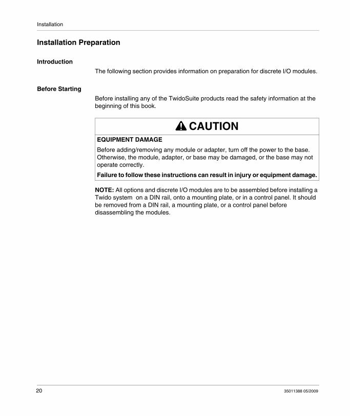
Installation Preparation
Introduction
The following section provides information on preparation for discrete I/O modules.
Before Starting
Before installing any of the TwidoSuite products read the safety information at the beginning of this book.
NOTE: All options and discrete I/O modules are to be assembled before installing a Twido system on a DIN rail, onto a mounting plate, or in a control panel. It should be removed from a DIN rail, a mounting plate, or a control panel before disassembling the modules.
CAUTIONEQUIPMENT DAMAGE
Before adding/removing any module or adapter, turn off the power to the base. Otherwise, the module, adapter, or base may be damaged, or the base may not operate correctly.
Failure to follow these instructions can result in injury or equipment damage.
20 35011388 05/2009
Installation
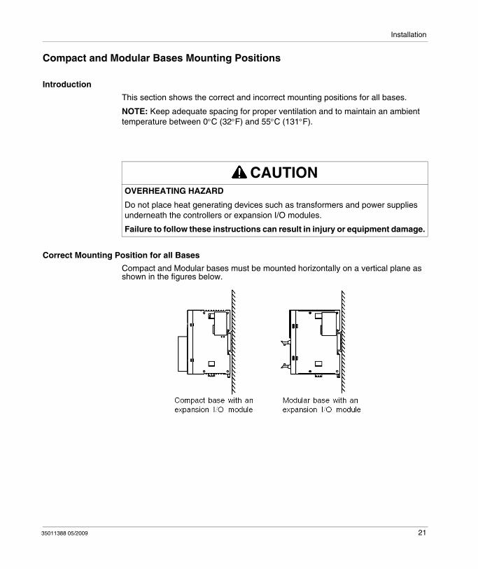
Compact and Modular Bases Mounting Positions
Introduction
This section shows the correct and incorrect mounting positions for all bases.
NOTE: Keep adequate spacing for proper ventilation and to maintain an ambient temperature between 0°C (32°F) and 55°C (131°F).
Correct Mounting Position for all Bases
Compact and Modular bases must be mounted horizontally on a vertical plane as shown in the figures below.
CAUTIONOVERHEATING HAZARD
Do not place heat generating devices such as transformers and power supplies underneath the controllers or expansion I/O modules.
Failure to follow these instructions can result in injury or equipment damage.
35011388 05/2009 21

Installation
Correct and Incorrect Mounting Positions for Compact Bases
A Compact base should only be positioned as shown in "Correct Mounting Position for all Bases" figure. When the ambient temperature is 35°C (95°F) or below, the Compact base can also be mounted upright on a horizontal plane as shown in (1). When the ambient temperature is 40°C (104°F) or below, the Compact base can also be mounted sideways on a vertical place as shown in figure (2). Figure (3) shows an incorrect mounting position.
Incorrect Mounting Positions for Modular Bases
A Modular base should only be positioned as shown in "Correct Mounting Position for all Bases" figure. The figures below show the incorrect mounting positions for all Modular bases.
22 35011388 05/2009

Installation
Assembling an Expansion I/O module to a Base
Introduction
This section shows how to assemble an expansion I/O module to a base. This procedure is for both Compact and Modular bases. Your base and expansion I/O module may differ from the illustrations in this procedure.
Assembling an Expansion I/O Module to a Base.
The following procedure shows how to assemble a base and an expansion I/O module together.
WARNINGUNEXPECTED EQUIPMENT OPERATION
Update the software each time you change the hardware configuration of the I/O expansion bus. Otherwise, the expansion bus will no longer operate while the local base inputs and outputs will continue to operate.
Failure to follow these instructions can result in death, serious injury, or equipment damage.
Step Action
1 Remove the expansion connector cover from the base.
2 Verify that the black latch button on the I/O module is in the up position.
35011388 05/2009 23

Installation
3 Align the connector on the left side of the Expansion I/O module with the connector on the right side of the base.
4 Press the expansion I/O module to the base until it "clicks" into place.
5 Push down the black latch button on the top of the expansion I/O module to lock the module to the base.
Step Action
24 35011388 05/2009

Installation
Disassembling an Expansion I/O Module from a Base
Introduction
This section describes how to disassemble an expansion I/O module from a base. This procedure is for both Compact and Modular bases. Your base and expansion I/O module may differ from the illustrations in these procedures but the basic mechanism procedures are still applicable.
Disassembling an Expansion I/O Module from a Base.
The following procedure describes how to disassemble an expansion I/O module from a base.
Step Action
1 Remove the assembled base and module from the DIN rail before disassembling them, see The DIN Rail, page 89.
2 Push up the black latch from the bottom of the expansion I/O module to disengage it from the base.
3 Pull apart the base and module.
35011388 05/2009 25
Installation
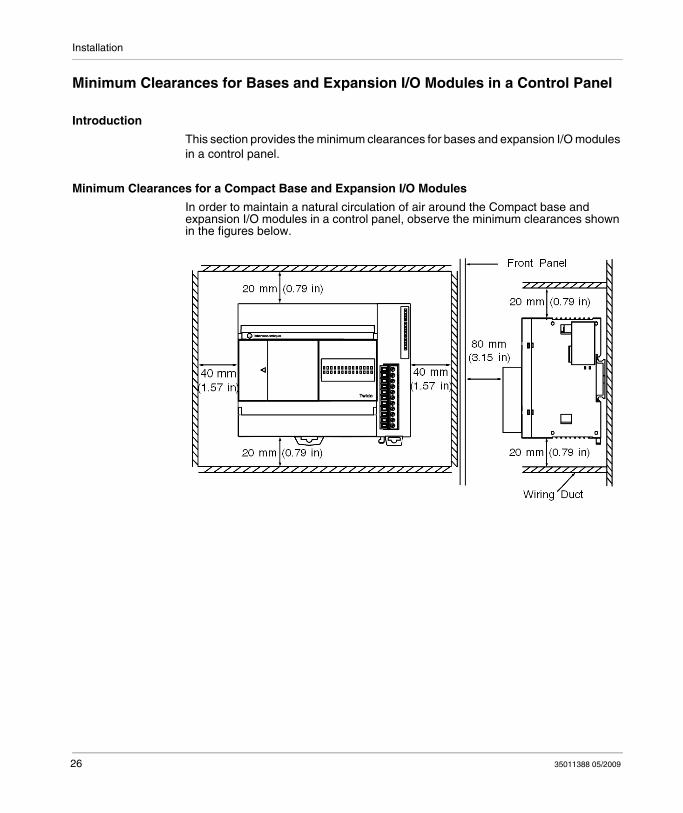
Minimum Clearances for Bases and Expansion I/O Modules in a Control Panel
Introduction
This section provides the minimum clearances for bases and expansion I/O modules in a control panel.
Minimum Clearances for a Compact Base and Expansion I/O Modules
In order to maintain a natural circulation of air around the Compact base and expansion I/O modules in a control panel, observe the minimum clearances shown in the figures below.
26 35011388 05/2009
Installation
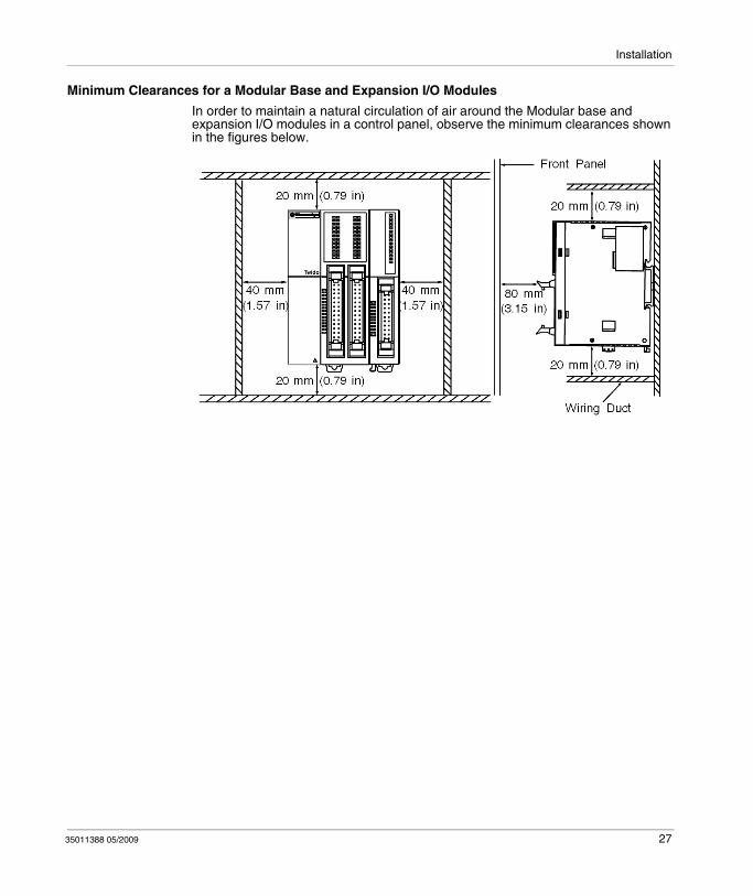
Minimum Clearances for a Modular Base and Expansion I/O Modules
In order to maintain a natural circulation of air around the Modular base and expansion I/O modules in a control panel, observe the minimum clearances shown in the figures below.
35011388 05/2009 27
Installation
2.2 Installation of Discrete I/O Modules
Introduction
This section provides Information about installing the Discrete I/O modules.
What's in this Section?
This section contains the following topics:
Topic Page
Dimensions for Discrete I/O Modules 29
How to Directly Mount a Discrete I/O Module on a Panel Surface 32
How to Install and Remove a Discrete I/O Module from a DIN Rail 34
28 35011388 05/2009
Installation
Dimensions for Discrete I/O Modules
Introduction
The following section shows the dimensions for all discrete I/O modules.
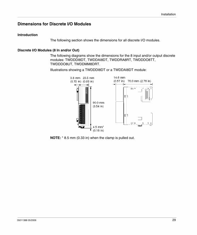
Discrete I/O Modules (8 In and/or Out)
The following diagrams show the dimensions for the 8 input and/or output discrete modules: TWDDDI8DT, TWDDAI8DT, TWDDRA8RT, TWDDDO8TT, TWDDDO8UT, TWDDMM8DRT.
Illustrations showing a TWDDDI8DT or a TWDDAI8DT module:
NOTE: * 8.5 mm (0.33 in) when the clamp is pulled out.
35011388 05/2009 29
Installation
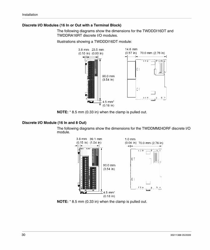
Discrete I/O Modules (16 In or Out with a Terminal Block)
The following diagrams show the dimensions for the TWDDDI16DT and TWDDRA16RT discrete I/O modules.
Illustrations showing a TWDDDI16DT module:
NOTE: * 8.5 mm (0.33 in) when the clamp is pulled out.
Discrete I/O Module (16 In and 8 Out)
The following diagrams show the dimensions for the TWDDMM24DRF discrete I/O module.
NOTE: * 8.5 mm (0.33 in) when the clamp is pulled out.
30 35011388 05/2009

Installation
Discrete I/O Modules (16 In or Out with a Connector)
The following diagrams show the dimensions for the TWDDDI16DK, TWDDDO16TK, and TWDDDO16UK discrete I/O modules.
Illustrations showing a TWDDDI16DK module:
NOTE: * 8.5 mm (0.33 in) when the clamp is pulled out.
Discrete I/O Modules (32 In or Out)
The following diagrams show the dimensions for the TWDDDI32DK, TWDDDO32TK, and TWDDDO32UK discrete I/O modules.
Illustrations showing a TWDDDI32DK module:
NOTE: * 8.5 mm (0.33 in) when the clamp is pulled out.
35011388 05/2009 31

Installation
How to Directly Mount a Discrete I/O Module on a Panel Surface
Introduction
This section shows how to install mounting strips directly on discrete I/O modules. This section also provides mounting hole layouts for each module. Your module may differ from the illustrations in these procedures but the basic mechanism procedures are applicable.
Installing a Mounting Strip
The following procedure shows how to install a mounting strip.
Step Action
1 Remove the clamp from the back side of the module by pushing the clamp inward.
2 Insert the mounting strip, with the hook entering last, into the slot where the clamp was removed.
3 Slide the mounting strip into the slot until the hook enters into the recess in the module.
32 35011388 05/2009

Installation
Mounting Hole Layout for Discrete I/O Modules
The following diagram shows the mounting hole layout for the discrete I/O modules.
35011388 05/2009 33

Installation
How to Install and Remove a Discrete I/O Module from a DIN Rail
Introduction
This section describes how to install and remove discrete I/O modules from a DIN rail. The device you want to install or remove may differ from the illustrations in these procedures but the basic mechanism procedures are applicable.
NOTE: When mounting discrete I/O modules on a DIN rail, use two end stops, type AB1-AB8P35 or equivalent.
For additional information about the DIN rail,
see The DIN Rail. The DIN Rail, page 89
How to Install a Discrete I/O Module on a DIN Rail
The following procedure shows how to install a discrete I/O module on a DIN rail.
Step Action
1 Fasten the DIN rail to a panel using screws.
2 Pull out the clamp at the bottom of the base and module assembly.
34 35011388 05/2009
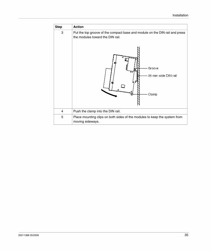
Installation
3 Put the top groove of the compact base and module on the DIN rail and press the modules toward the DIN rail.
4 Push the clamp into the DIN rail.
5 Place mounting clips on both sides of the modules to keep the system from moving sideways.
Step Action
35011388 05/2009 35
Installation
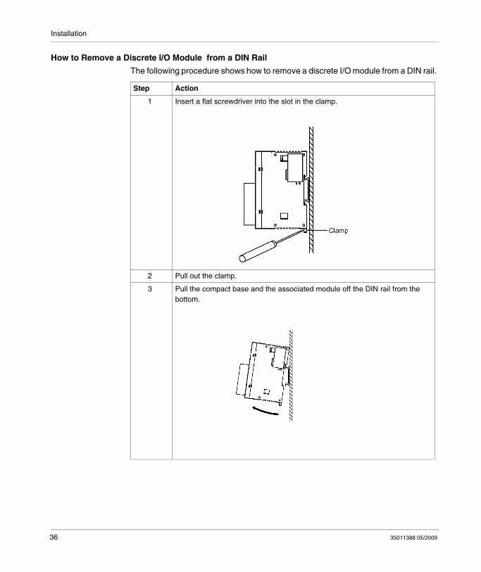
How to Remove a Discrete I/O Module from a DIN Rail
The following procedure shows how to remove a discrete I/O module from a DIN rail.
Step Action
1 Insert a flat screwdriver into the slot in the clamp.
2 Pull out the clamp.
3 Pull the compact base and the associated module off the DIN rail from the bottom.
36 35011388 05/2009
35011388 05/2009
3
Description of Discrete I/O Modules
35011388 05/2009
Description of Discrete I/O Modules
Introduction
This chapter provides descriptions, overviews, parts, specifications, wiring rules and recommendations, and wiring schematics for the Twido Discrete I/O modules.
What's in this Chapter?
This chapter contains the following sections:
Section Topic Page
3.1 Discrete I/O Modules Description 38
3.2 Wiring Rules and Recommendations for Discrete I/O Modules 42
3.3 Specifications and Wiring Diagrams for Discrete Input Modules 47
3.4 Specifications and Wiring Diagrams for Relay Output Modules 59
3.5 Specifications and Wiring Diagrams for Transistor Output Modules
67
3.6 Specifications and Wiring Diagrams for Discrete Mixed I/O Modules
77
37

Description of Discrete I/O Modules
3.1 Discrete I/O Modules Description
Introduction
This section provides an overview and a parts description of the Discrete I/O modules.
What's in this Section?
This section contains the following topics:
Topic Page
Overview of Discrete I/O Modules 39
Parts Description of Discrete I/O Modules 40
38 35011388 05/2009
Description of Discrete I/O Modules
Overview of Discrete I/O Modules
Introduction
The following section provides an overview of the discrete I/O modules.
Illustrations
The following illustrations are the discrete input, output, and mixed I/O modules.
35011388 05/2009 39
Description of Discrete I/O Modules
Parts Description of Discrete I/O Modules
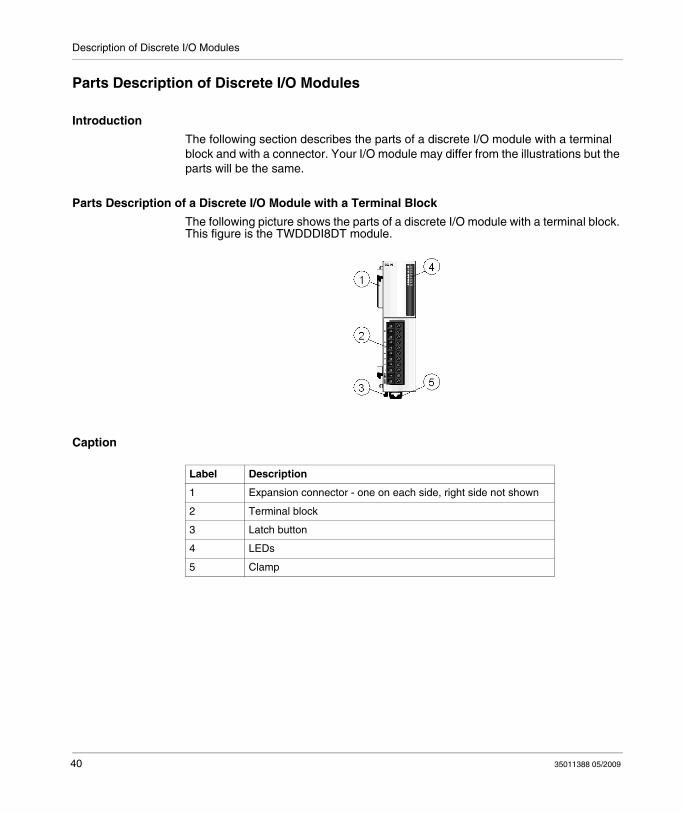
Introduction
The following section describes the parts of a discrete I/O module with a terminal block and with a connector. Your I/O module may differ from the illustrations but the parts will be the same.
Parts Description of a Discrete I/O Module with a Terminal Block
The following picture shows the parts of a discrete I/O module with a terminal block. This figure is the TWDDDI8DT module.
Caption
Label Description
1 Expansion connector - one on each side, right side not shown
2 Terminal block
3 Latch button
4 LEDs
5 Clamp
40 35011388 05/2009
Description of Discrete I/O Modules
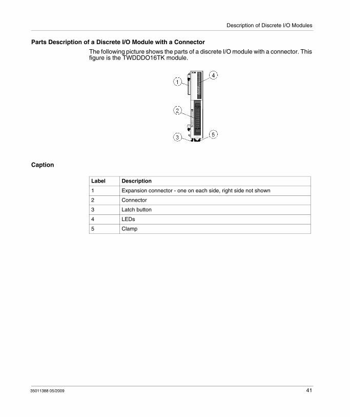
Parts Description of a Discrete I/O Module with a Connector
The following picture shows the parts of a discrete I/O module with a connector. This figure is the TWDDDO16TK module.
Caption
Label Description
1 Expansion connector - one on each side, right side not shown
2 Connector
3 Latch button
4 LEDs
5 Clamp
35011388 05/2009 41

Description of Discrete I/O Modules
3.2 Wiring Rules and Recommendations for Discrete I/O Modules
Wiring Rules and Recommendations for Discrete I/O Modules
Introduction
There are several rules that must be followed when wiring a discrete I/O module. Recommendations, when needed, are provided on how to comply with the rules.
DANGERHAZARD OF ELECTRIC SHOCK, EXPLOSION OR ARC FLASH
Remove all power from all devices before inspecting, installing, removing, wiring, or servicing any inputs, outputs, or hardware.Always use a properly rated voltage sensing device to confirm power is off.Remove the terminal block before installing/removing the module from the rail, rack, or enclosure. Terminal blocks must be connected or disconnected with sensor and preactuator voltage switched off.Replace and secure all covers or elements of the system and confirm that a proper ground connection exists before applying power to the unit.Use only the specified voltage when operating your Twido and associated products.
Failure to follow these instructions will result in death or serious injury.
WARNINGMALFUNCTION OF OUTPUTS
Use appropriate safety interlocks where personal and/or equipment hazards exist. Outputs can malfunction and remain ON or OFF.
Failure to follow these instructions can result in death, serious injury, or equipment damage.
42 35011388 05/2009
Description of Discrete I/O Modules
Rules
Each terminal accepts up to two 18 AWG (0.82 mm2) through 28 AWG (0.08
mm2) fitted with cable ends or tags.
The power supply wire are to be between 18 AWG (0.82 mm2) and 22 AWG (0.33
mm2). Use the shortest wire length possible.
The grounding wire is to be 16 AWG (1.30 mm2).Power supply wires routed inside the panel must be kept separate from power wires, I/O wiring and communication wiring. Route wiring in separate cable ducting.Verify that the operating conditions and environments are within the specification values.Use proper wire size to meet voltage and current requirements.
Terminal Tightening Torque
Recommended tightening torque of terminal blocks is listed for all products on the product label.
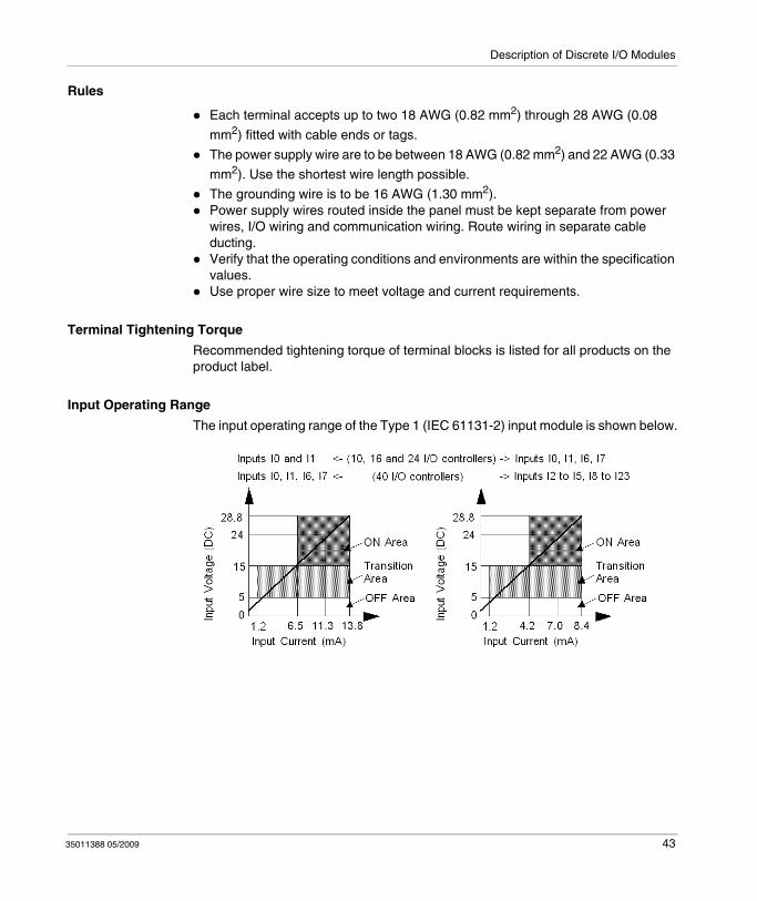
Input Operating Range
The input operating range of the Type 1 (IEC 61131-2) input module is shown below.
35011388 05/2009 43
Description of Discrete I/O Modules
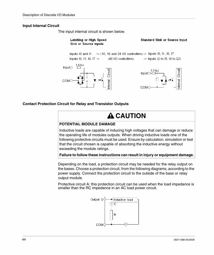
Input Internal Circuit
The input internal circuit is shown below.
Contact Protection Circuit for Relay and Transistor Outputs
Depending on the load, a protection circuit may be needed for the relay output on the bases. Choose a protection circuit, from the following diagrams, according to the power supply. Connect the protection circuit to the outside of the base or relay output module.
Protective circuit A: this protection circuit can be used when the load impedance is smaller than the RC impedance in an AC load power circuit.
CAUTIONPOTENTIAL MODULE DAMAGE
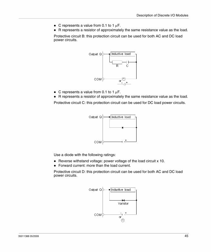
Inductive loads are capable of inducing high voltages that can damage or reduce the operating life of modules outputs. When driving inductive loads one of the following protective circuits must be used. Ensure by calculation, simulation or test that the circuit chosen is capable of absorbing the inductive energy without exceeding the module ratings.
Failure to follow these instructions can result in injury or equipment damage.
44 35011388 05/2009
Description of Discrete I/O Modules
C represents a value from 0.1 to 1 μF.R represents a resistor of approximately the same resistance value as the load.
Protective circuit B: this protection circuit can be used for both AC and DC load power circuits.
C represents a value from 0.1 to 1 μF.R represents a resistor of approximately the same resistance value as the load.
Protective circuit C: this protection circuit can be used for DC load power circuits.
Use a diode with the following ratings:
Reverse withstand voltage: power voltage of the load circuit x 10.Forward current: more than the load current.
Protective circuit D: this protection circuit can be used for both AC and DC load power circuits.
35011388 05/2009 45
Description of Discrete I/O Modules
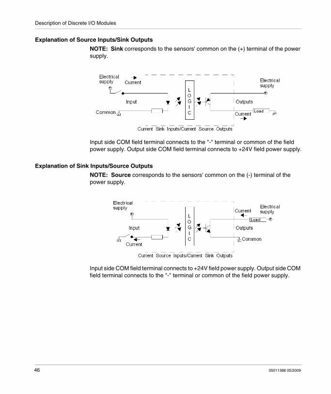
Explanation of Source Inputs/Sink Outputs
NOTE: Sink corresponds to the sensors' common on the (+) terminal of the power supply.
Input side COM field terminal connects to the "-" terminal or common of the field power supply. Output side COM field terminal connects to +24V field power supply.
Explanation of Sink Inputs/Source Outputs
NOTE: Source corresponds to the sensors' common on the (-) terminal of the power supply.
Input side COM field terminal connects to +24V field power supply. Output side COM field terminal connects to the "-" terminal or common of the field power supply.
46 35011388 05/2009
Description of Discrete I/O Modules
3.3 Specifications and Wiring Diagrams for Discrete Input Modules
Introduction
This section provides general, electrical, input and functional specifications, and wiring diagrams description for Discrete Input modules.
What's in this Section?
This section contains the following topics:
Topic Page
General Specifications for the Discrete Input Modules 48
Electrical Specifications for the Discrete Input Modules 49
Input Specifications for the Discrete Input Modules 50
Discrete Input Modules Wiring Diagrams 53
35011388 05/2009 47

Description of Discrete I/O Modules
General Specifications for the Discrete Input Modules
Introduction
This section presents the general specifications for the discrete input modules.
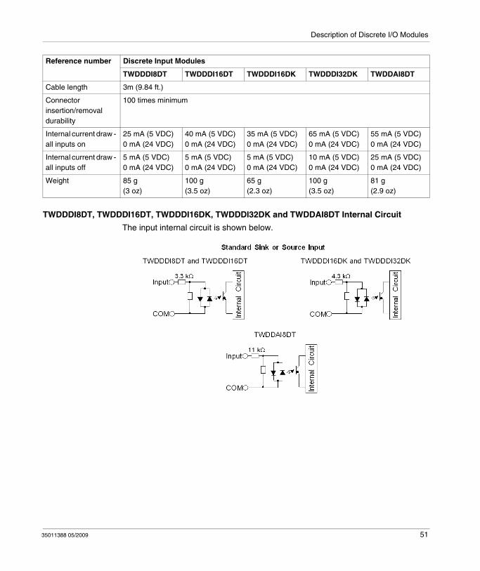
TWDDDI8DT, TWDDDI16DT, TWDDDI16DK, TWDDDI32DK and TWDDAI8DT Normal Operating Specifications
WARNINGHAZARDS OF UNINTENDED EQUIPMENT OPERATION & EQUIPMENT DAM-AGE
Do not exceed any of the rated values specified below.
Failure to follow these instructions can result in death, serious injury, or equipment damage.
Reference number Discrete Input Modules
TWDDDI8DT TWDDDI16DT TWDDDI16DK TWDDDI32DK TWDDAI8DT
Ambient operating temperature
0°C to 55°C (32°F to 131°F)
Storage temperature (°C)
- 25°C to +70°C (-13°F to +158°F)
Relative humidity 30 to 95% (non-condensing)
Degree of pollution 2 (IEC60664)
Degree of protection IP 20
Corrosion immunity Free from corrosive gases
Altitude Operation: 0 to 2,000 m (0 to 6,560 ft)Transport: 0 to 3,000 m (0 to 9,840 ft)
Resistance to vibration
When mounted on a DIN rail:10 to 57 Hz, amplitude 0.075 mm, 57 to 150 Hz, acceleration 9.8 m/s2 (1G)When mounted on a panel surface:2 to 25 Hz, amplitude 1.6 mm, 25 to 100 Hz, acceleration 39.2 m/s2 (4G)
Impact strength 147 m/s2 (15G) for 11ms duration
Weight 85 g(3 oz)
100 g(3.5 oz)
65 g(2.3 oz)
100 g(3.5 oz)
81 g(2.9 oz)
48 35011388 05/2009

Description of Discrete I/O Modules
Electrical Specifications for the Discrete Input Modules
Introduction
This section presents the electrical specifications for the discrete input modules.
TWDDDI8DT, TWDDDI16DT, TWDDDI16DK, TWDDDI32DK and TWDDAI8DT Electrical Specifications
WARNINGHAZARDS OF UNINTENDED EQUIPMENT OPERATION & EQUIPMENT DAM-AGE
Do not exceed any of the rated values specified below.
Failure to follow these instructions can result in death, serious injury, or equipment damage.
Reference number Discrete Input Modules
TWDDDI8DT TWDDDI16DT TWDDDI16DK TWDDDI32DK TWDDAI8DT
Isolation Between input terminals and internal circuit: photocoupler isolated (isolation protection up to 500 V)Between input terminals: not isolated
Connector insertion/removal durability
100 times minimum
Internal current draw - all inputs on
25 mA (5 VDC)0 mA (24 VDC)
40 mA (5 VDC)0 mA (24 VDC)
35 mA (5 VDC)0 mA (24 VDC)
65 mA (5 VDC)0 mA (24 VDC)
55 mA (5 VDC)0 mA (24 VDC)
Internal current draw - all inputs off
5 mA (5 VDC)0 mA (24 VDC)
5 mA (5 VDC)0 mA (24 VDC)
5 mA (5 VDC)0 mA (24 VDC)
10 mA (5 VDC)0 mA (24 VDC)
25 mA (5 VDC)0 mA (24 VDC)
35011388 05/2009 49
Description of Discrete I/O Modules
Input Specifications for the Discrete Input Modules
Introduction
This section presents the input specifications for the discrete input modules.
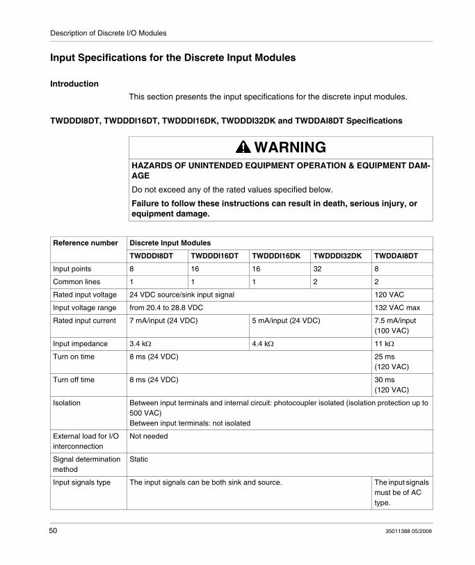
TWDDDI8DT, TWDDDI16DT, TWDDDI16DK, TWDDDI32DK and TWDDAI8DT Specifications
WARNINGHAZARDS OF UNINTENDED EQUIPMENT OPERATION & EQUIPMENT DAM-AGE
Do not exceed any of the rated values specified below.
Failure to follow these instructions can result in death, serious injury, or equipment damage.
Reference number Discrete Input Modules
TWDDDI8DT TWDDDI16DT TWDDDI16DK TWDDDI32DK TWDDAI8DT
Input points 8 16 16 32 8
Common lines 1 1 1 2 2
Rated input voltage 24 VDC source/sink input signal 120 VAC
Input voltage range from 20.4 to 28.8 VDC 132 VAC max
Rated input current 7 mA/input (24 VDC) 5 mA/input (24 VDC) 7.5 mA/input (100 VAC)
Input impedance 3.4 kΩ 4.4 kΩ 11 kΩ
Turn on time 8 ms (24 VDC) 25 ms (120 VAC)
Turn off time 8 ms (24 VDC) 30 ms (120 VAC)
Isolation Between input terminals and internal circuit: photocoupler isolated (isolation protection up to 500 VAC)Between input terminals: not isolated
External load for I/O interconnection
Not needed
Signal determination method
Static
Input signals type The input signals can be both sink and source. The input signals must be of AC type.
50 35011388 05/2009
Description of Discrete I/O Modules
TWDDDI8DT, TWDDDI16DT, TWDDDI16DK, TWDDDI32DK and TWDDAI8DT Internal Circuit
The input internal circuit is shown below.
Cable length 3m (9.84 ft.)
Connector insertion/removal durability
100 times minimum
Internal current draw - all inputs on
25 mA (5 VDC)0 mA (24 VDC)
40 mA (5 VDC)0 mA (24 VDC)
35 mA (5 VDC)0 mA (24 VDC)
65 mA (5 VDC)0 mA (24 VDC)
55 mA (5 VDC)0 mA (24 VDC)
Internal current draw - all inputs off
5 mA (5 VDC)0 mA (24 VDC)
5 mA (5 VDC)0 mA (24 VDC)
5 mA (5 VDC)0 mA (24 VDC)
10 mA (5 VDC)0 mA (24 VDC)
25 mA (5 VDC)0 mA (24 VDC)
Weight 85 g(3 oz)
100 g(3.5 oz)
65 g(2.3 oz)
100 g(3.5 oz)
81 g(2.9 oz)
Reference number Discrete Input Modules
TWDDDI8DT TWDDDI16DT TWDDDI16DK TWDDDI32DK TWDDAI8DT
35011388 05/2009 51

Description of Discrete I/O Modules
TWDDDI8DT, TWDDDI16DT, TWDDDI16DK, TWDDDI32DK and TWDDAI8DT Usage Limits
When using TWDDDI16DT at 55°C (131°F) in the normal mounting direction, limit the inputs which turn on simultaneously along line (1). At 45°C (113°F), all inputs can be turned on simultaneously at 28.8 VDC as indicated with line (2).
When using TWDDDI16DK and TWDDDI32DK at 55°C (131°F), limit the inputs which turn on simultaneously on each connector along line (3). This limitation applies per connector. At 30°C (86°F), all inputs can be turned on simultaneously at 28.8 VDC as indicated with line (4).
When using TWDDDI8DT, all inputs can be turned on simultaneously at 55°C (131°F), input voltage 28.8 VDC.
52 35011388 05/2009
Description of Discrete I/O Modules
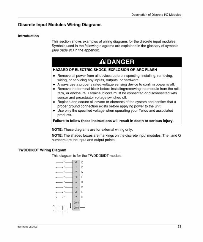
Discrete Input Modules Wiring Diagrams
Introduction
This section shows examples of wiring diagrams for the discrete input modules. Symbols used in the following diagrams are explained in the glossary of symbols (see page 91) in the appendix.
NOTE: These diagrams are for external wiring only.
NOTE: The shaded boxes are markings on the discrete input modules. The I and Q numbers are the input and output points.
TWDDDI8DT Wiring Diagram
This diagram is for the TWDDDI8DT module.
DANGERHAZARD OF ELECTRIC SHOCK, EXPLOSION OR ARC FLASH
Remove all power from all devices before inspecting, installing, removing, wiring, or servicing any inputs, outputs, or hardware.Always use a properly rated voltage sensing device to confirm power is off.Remove the terminal block before installing/removing the module from the rail, rack, or enclosure. Terminal blocks must be connected or disconnected with sensor and preactuator voltage switched off.Replace and secure all covers or elements of the system and confirm that a proper ground connection exists before applying power to the unit.Use only the specified voltage when operating your Twido and associated products.
Failure to follow these instructions will result in death or serious injury.
35011388 05/2009 53

Description of Discrete I/O Modules
The two COM terminals are connected together internally.Both sink and source input wiring are supportedA is the sink wiring (positive logic).B is the source wiring (negative logic).
TWDDAI8DT Wiring Diagram
This diagram is for the TWDDAI8DT module.
The two COM terminals are not connected together internally.
DANGERHAZARD OF ELECTRIC SHOCK, EXPLOSION OR ARC FLASH
Turn off all power before starting installation, removal, wiring, maintenance or inspection of the smart relay system.
Failure to follow these instructions will result in death or serious injury.
54 35011388 05/2009
Description of Discrete I/O Modules
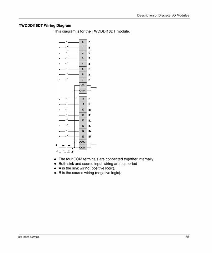
TWDDDI16DT Wiring Diagram
This diagram is for the TWDDDI16DT module.
The four COM terminals are connected together internally.Both sink and source input wiring are supportedA is the sink wiring (positive logic).B is the source wiring (negative logic).
35011388 05/2009 55

Description of Discrete I/O Modules
TWDDDI16DK Wiring Diagram
This diagram is for the TWDDDI16DK module.
The two COM terminals are connected together internally.Both sink and source input wiring are supportedA is the sink wiring (positive logic).B is the source wiring (negative logic).
56 35011388 05/2009
Description of Discrete I/O Modules
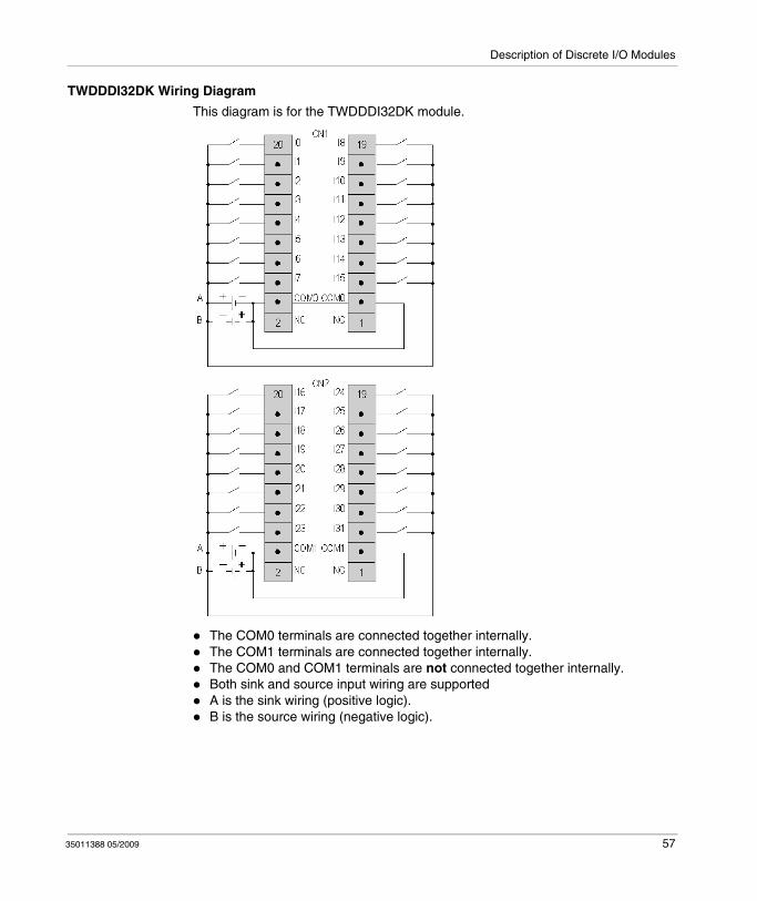
TWDDDI32DK Wiring Diagram
This diagram is for the TWDDDI32DK module.
The COM0 terminals are connected together internally. The COM1 terminals are connected together internally.The COM0 and COM1 terminals are not connected together internally.Both sink and source input wiring are supportedA is the sink wiring (positive logic).B is the source wiring (negative logic).
35011388 05/2009 57
Description of Discrete I/O Modules
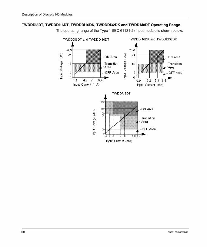
TWDDDI8DT, TWDDDI16DT, TWDDDI16DK, TWDDDI32DK and TWDDAI8DT Operating Range
The operating range of the Type 1 (IEC 61131-2) input module is shown below.
58 35011388 05/2009
Description of Discrete I/O Modules
3.4 Specifications and Wiring Diagrams for Relay Output Modules
Introduction
This section provides general, electrical, relay output, and functional specifications for Relay Output modules.
What's in this Section?
This section contains the following topics:
Topic Page
General Specifications for the Relay Output Modules 60
Electrical Specifications for the Relay Output Modules 61
Output Specifications for the Relay Output Modules 62
Relay Output Modules Wiring Diagrams 64
35011388 05/2009 59
Description of Discrete I/O Modules
General Specifications for the Relay Output Modules
Introduction
This section presents the general specifications for the relay output modules.
TWDDRA8RT and TWDDRA16RT Specifications
WARNINGHAZARDS OF UNINTENDED EQUIPMENT OPERATION & EQUIPMENT DAM-AGE
Do not exceed any of the rated values specified below.
Failure to follow these instructions can result in death, serious injury, or equipment damage.
Reference number Relay Output Modules
TWDDRA8RT TWDDRA16RT
Ambient operating temperature 0°C to 55°C (32°F to 131°F)
Storage temperature (°C) - 25°C to +70°C (-13°F to +158°F)
Relative humidity 30 to 95% (non-condensing)
Degree of pollution 2 (IEC60664)
Degree of protection IP 20
Corrosion immunity Free from corrosives gases
Altitude Operation: 0 to 2,000 m (0 to 6,560 ft)Transport: 0 to 3,000 m (0 to 9,840 ft)
Resistance to vibration When mounted on a DIN rail:10 to 57 Hz, amplitude 0.075 mm, 57 to 150 Hz, acceleration 9.8 m/s2 (1G)When mounted on a panel surface:2 to 25 Hz, amplitude 1.6 mm, 25 to 100 Hz, acceleration 39.2 m/s2 (4G)
Impact strength 147 m/s2 (15G) for 11ms duration
Weight 110 g(3.9 oz)
145 g(5.1 oz)
60 35011388 05/2009
Description of Discrete I/O Modules
Electrical Specifications for the Relay Output Modules
Introduction
This section presents the electrical specifications for the relay output modules.
TWDDRA8RT and TWDDRA16RT Specifications
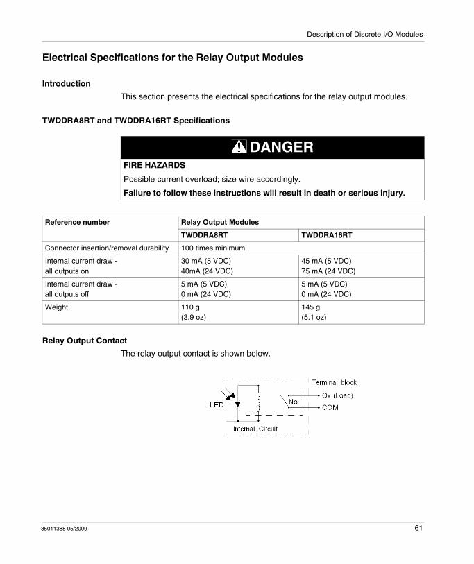
Relay Output Contact
The relay output contact is shown below.
DANGERFIRE HAZARDS
Possible current overload; size wire accordingly.
Failure to follow these instructions will result in death or serious injury.
Reference number Relay Output Modules
TWDDRA8RT TWDDRA16RT
Connector insertion/removal durability 100 times minimum
Internal current draw -all outputs on
30 mA (5 VDC)40mA (24 VDC)
45 mA (5 VDC)75 mA (24 VDC)
Internal current draw -all outputs off
5 mA (5 VDC)0 mA (24 VDC)
5 mA (5 VDC)0 mA (24 VDC)
Weight 110 g(3.9 oz)
145 g(5.1 oz)
35011388 05/2009 61
Description of Discrete I/O Modules
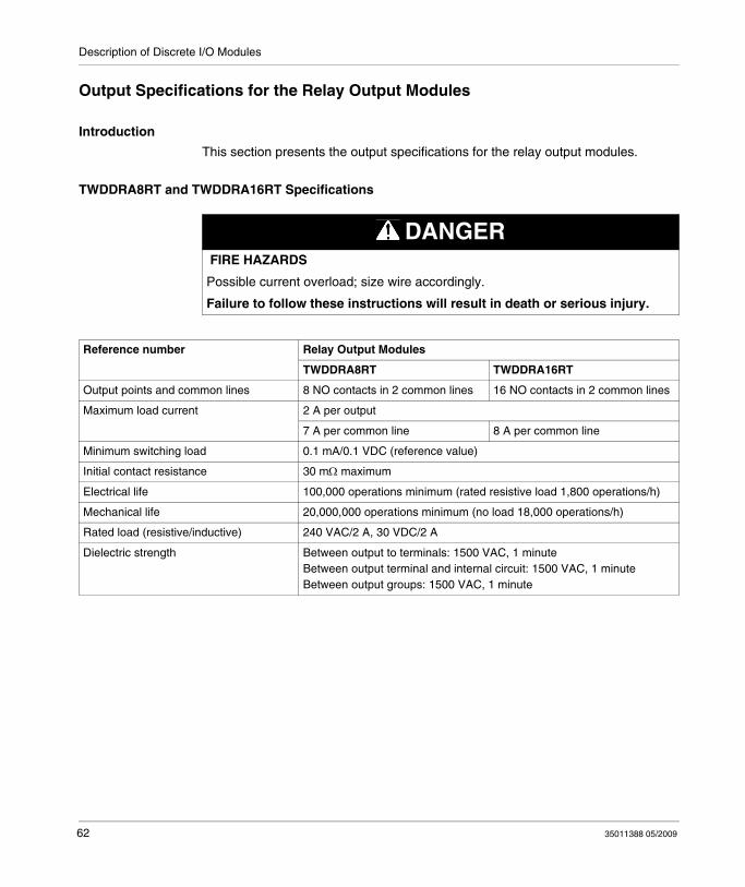
Output Specifications for the Relay Output Modules
Introduction
This section presents the output specifications for the relay output modules.
TWDDRA8RT and TWDDRA16RT Specifications
DANGER FIRE HAZARDS
Possible current overload; size wire accordingly.
Failure to follow these instructions will result in death or serious injury.
Reference number Relay Output Modules
TWDDRA8RT TWDDRA16RT
Output points and common lines 8 NO contacts in 2 common lines 16 NO contacts in 2 common lines
Maximum load current 2 A per output
7 A per common line 8 A per common line
Minimum switching load 0.1 mA/0.1 VDC (reference value)
Initial contact resistance 30 mΩ maximum
Electrical life 100,000 operations minimum (rated resistive load 1,800 operations/h)
Mechanical life 20,000,000 operations minimum (no load 18,000 operations/h)
Rated load (resistive/inductive) 240 VAC/2 A, 30 VDC/2 A
Dielectric strength Between output to terminals: 1500 VAC, 1 minuteBetween output terminal and internal circuit: 1500 VAC, 1 minuteBetween output groups: 1500 VAC, 1 minute
62 35011388 05/2009

Description of Discrete I/O Modules
TWDDRA8RT and TWDDRA16RT Delay
The output delay is shown below.
35011388 05/2009 63
Description of Discrete I/O Modules
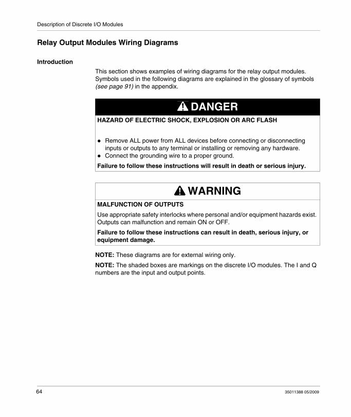
Relay Output Modules Wiring Diagrams
Introduction
This section shows examples of wiring diagrams for the relay output modules. Symbols used in the following diagrams are explained in the glossary of symbols (see page 91) in the appendix.
NOTE: These diagrams are for external wiring only.
NOTE: The shaded boxes are markings on the discrete I/O modules. The I and Q numbers are the input and output points.
DANGERHAZARD OF ELECTRIC SHOCK, EXPLOSION OR ARC FLASH
Remove ALL power from ALL devices before connecting or disconnecting inputs or outputs to any terminal or installing or removing any hardware.Connect the grounding wire to a proper ground.
Failure to follow these instructions will result in death or serious injury.
WARNINGMALFUNCTION OF OUTPUTS
Use appropriate safety interlocks where personal and/or equipment hazards exist. Outputs can malfunction and remain ON or OFF.
Failure to follow these instructions can result in death, serious injury, or equipment damage.
64 35011388 05/2009
Description of Discrete I/O Modules
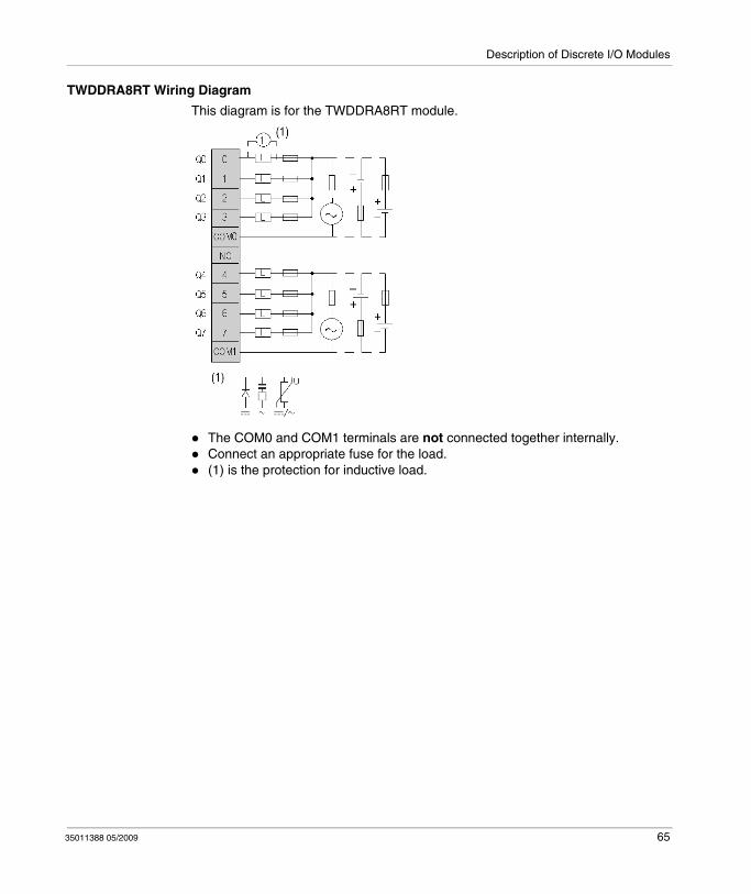
TWDDRA8RT Wiring Diagram
This diagram is for the TWDDRA8RT module.
The COM0 and COM1 terminals are not connected together internally.Connect an appropriate fuse for the load.(1) is the protection for inductive load.
35011388 05/2009 65
Description of Discrete I/O Modules
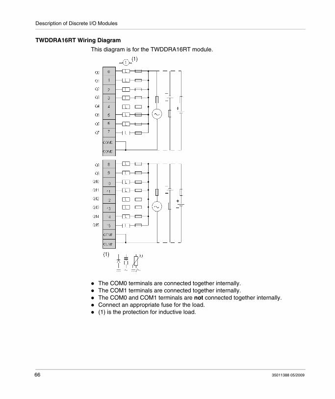
TWDDRA16RT Wiring Diagram
This diagram is for the TWDDRA16RT module.
The COM0 terminals are connected together internally. The COM1 terminals are connected together internally.The COM0 and COM1 terminals are not connected together internally.Connect an appropriate fuse for the load.(1) is the protection for inductive load.
66 35011388 05/2009
Description of Discrete I/O Modules
3.5 Specifications and Wiring Diagrams for Transistor Output Modules
Introduction
This section provides general, electrical, output, and functional specifications for Transistor Output modules.
What's in this Section?
This section contains the following topics:
Topic Page
General Specifications for the Transistor Output Modules 68
Electrical Specifications for the Transistor Output Modules 69
Output Specifications for the Transistor Output Modules 70
Transistor Output Module Wiring Diagrams 72
35011388 05/2009 67

Description of Discrete I/O Modules
General Specifications for the Transistor Output Modules
Introduction
This section presents the general specifications for the transistor output modules.
TWDDDO8UT, TWDDDO16UK, TWDDDO32UK, TWDDDO8TT, TWDDDO16TK, and TWDDDO32TK Specifications
DANGERFIRE HAZARDS
Possible current overload; size wire accordingly.
Failure to follow these instructions will result in death or serious injury.
Reference number TWDDDO8UTTWDDDO8TT
TWDDDO16UKTWDDDO16TK
TWDDDO32UKTWDDDO32TK
Output type TWDDDO8UT, TWDDDO16UK and TWDDDO32UK are transistor sink outputsTWDDDO8TT, TWDDDO16TK and TWDDDO32TK are transistor source outputs
Ambient operating temperature
0°C to 55°C (32°F to 131°F)
Storage temperature - 25°C to +70°C (-13°F to +158°F)
Relative humidity 30 to 95% (non-condensing)
Degree of pollution 2 (IEC60664)
Degree of protection IP 20
Corrosion immunity Free from corrosive gases
Altitude Operation: 0 to 2,000 m (0 to 6,560 ft)Transport: 0 to 3,000 m (0 to 9,840 ft)
Resistance to vibration When mounted on a DIN rail:
10 to 57 Hz, amplitude 0.075 mm, 57 to 150 Hz, acceleration 9.8 m/s2 (1G)When mounted on a panel surface:
2 to 25 Hz, amplitude 1.6 mm, 25 to 100 Hz, acceleration 39.2 m/s2 (4G)
Impact strength 147 m/s2 (15G) for 11ms duration
Weight 85 g(3 oz)
70 g(2.5 oz)
105 g(3.7 oz)
68 35011388 05/2009
Description of Discrete I/O Modules
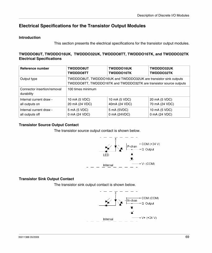
Electrical Specifications for the Transistor Output Modules
Introduction
This section presents the electrical specifications for the transistor output modules.
TWDDDO8UT, TWDDDO16UK, TWDDDO32UK, TWDDDO8TT, TWDDDO16TK, and TWDDDO32TK Electrical Specifications
Transistor Source Output Contact
The transistor source output contact is shown below.
Transistor Sink Output Contact
The transistor sink output contact is shown below.
Reference number TWDDDO8UTTWDDDO8TT
TWDDDO16UKTWDDDO16TK
TWDDDO32UKTWDDDO32TK
Output type TWDDDO8UT, TWDDDO16UK and TWDDDO32UK are transistor sink outputsTWDDDO8TT, TWDDDO16TK and TWDDDO32TK are transistor source outputs
Connector insertion/removal durability
100 times minimum
Internal current draw -all outputs on
10 mA (5 VDC)20 mA (24 VDC)
10 mA (5 VDC)40mA (24 VDC)
20 mA (5 VDC)70 mA (24 VDC)
Internal current draw -all outputs off
5 mA (5 VDC)0 mA (24 VDC)
5 mA (5VDC)0 mA (24VDC)
10 mA (5 VDC)0 mA (24 VDC)
35011388 05/2009 69

Description of Discrete I/O Modules
Output Specifications for the Transistor Output Modules
Introduction
This section presents the output specifications for the transistor output modules.
TWDDDO8UT, TWDDDO16UK, TWDDDO32UK, TWDDDO8TT, TWDDDO16TK, and TWDDDO32TK Output Specifications
DANGERFIRE HAZARDS
Possible current overload; size wire accordingly.
Failure to follow these instructions will result in death or serious injury.
Reference number TWDDDO8UTTWDDDO8TT
TWDDDO16UKTWDDDO16TK
TWDDDO32UKTWDDDO32TK
Output type TWDDDO8UT, TWDDDO16UK and TWDDDO32UK are transistor sink outputsTWDDDO8TT, TWDDDO16TK and TWDDDO32TK are transistor source outputs
Output points per common Line 8 points in 1 common line 16 points in 1 common line
32 points in 2 common lines
Rated load voltage 24 VDC
Operating load voltage range from 20.4 to 28.8 VDC
Rated load current 0.3 A per output 0.1 A per output
Maximum load current 0.36 A per output at maximum load(0.3 A at nominal load)3 A per common line
0.12 A per output at maximum load(0.1 A at nominal load)1 A per common line
Voltage drop (on voltage) 1 V maximum (voltage between COM and output terminals when output is on)
Inrush current 1 A maximum
Leakage current 0.1 mA maximum
Clamping voltage 39 V +/-1 V
Maximum lamp load 8 W
Inductive load L/R = 10 ms (28.8 VDC, 1 Hz)
70 35011388 05/2009
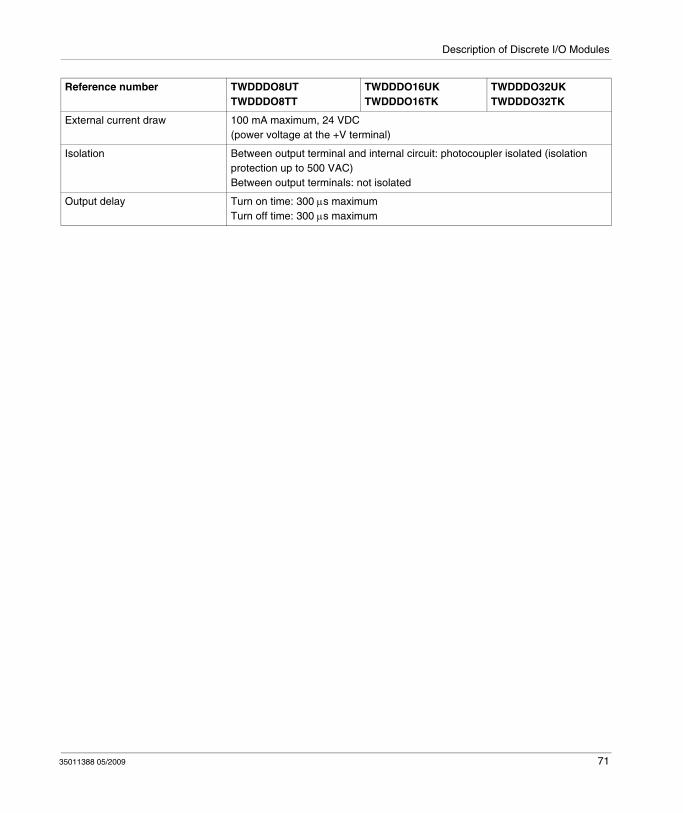
Description of Discrete I/O Modules
External current draw 100 mA maximum, 24 VDC(power voltage at the +V terminal)
Isolation Between output terminal and internal circuit: photocoupler isolated (isolation protection up to 500 VAC)Between output terminals: not isolated
Output delay Turn on time: 300 μs maximumTurn off time: 300 μs maximum
Reference number TWDDDO8UTTWDDDO8TT
TWDDDO16UKTWDDDO16TK
TWDDDO32UKTWDDDO32TK
35011388 05/2009 71

Description of Discrete I/O Modules
Transistor Output Module Wiring Diagrams
Introduction
This section shows examples of wiring diagrams for the transistor output modules. Symbols used in the following diagrams are explained in the glossary of symbols (see page 91) in the appendix.
NOTE: These diagrams are for external wiring only.
NOTE: The shaded boxes are markings on the discrete I/O modules. The I and Q numbers are the input and output points.
DANGERHAZARD OF ELECTRIC SHOCK, EXPLOSION OR ARC FLASH
Remove ALL power from ALL devices before connecting or disconnecting inputs or outputs to any terminal or installing or removing any hardware.Connect the grounding wire to a proper ground.
Failure to follow these instructions will result in death or serious injury.
WARNINGMALFUNCTION OF OUTPUTS
Use appropriate safety interlocks where personal and/or equipment hazards exist. Outputs can malfunction and remain ON or OFF.
Failure to follow these instructions can result in death, serious injury, or equipment damage.
72 35011388 05/2009
Description of Discrete I/O Modules
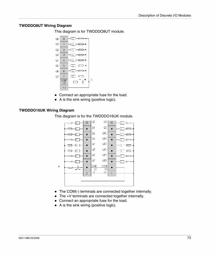
TWDDDO8UT Wiring Diagram
This diagram is for TWDDDO8UT module.
Connect an appropriate fuse for the load.A is the sink wiring (positive logic).
TWDDDO16UK Wiring Diagram
This diagram is for the TWDDDO16UK module.
The COM(-) terminals are connected together internally. The +V terminals are connected together internally.Connect an appropriate fuse for the load.A is the sink wiring (positive logic).
35011388 05/2009 73
Description of Discrete I/O Modules
TWDDDO32UK Wiring Diagram
This diagram is for the TWDDDO32UK module.
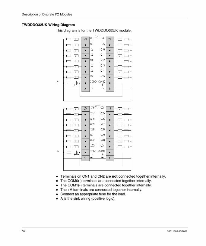
Terminals on CN1 and CN2 are not connected together internally. The COM0(-) terminals are connected together internally.The COM1(-) terminals are connected together internally.The +V terminals are connected together internally.Connect an appropriate fuse for the load.A is the sink wiring (positive logic).
74 35011388 05/2009
Description of Discrete I/O Modules
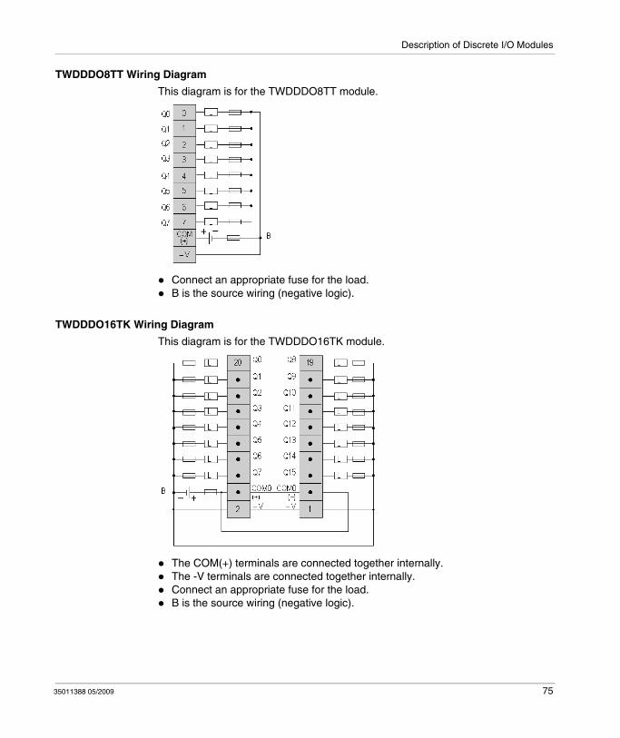
TWDDDO8TT Wiring Diagram
This diagram is for the TWDDDO8TT module.
Connect an appropriate fuse for the load.B is the source wiring (negative logic).
TWDDDO16TK Wiring Diagram
This diagram is for the TWDDDO16TK module.
The COM(+) terminals are connected together internally. The -V terminals are connected together internally.Connect an appropriate fuse for the load.B is the source wiring (negative logic).
35011388 05/2009 75
Description of Discrete I/O Modules
TWDDDO32TK Wiring Diagram
This diagram is for the TWDDDO32TK module.
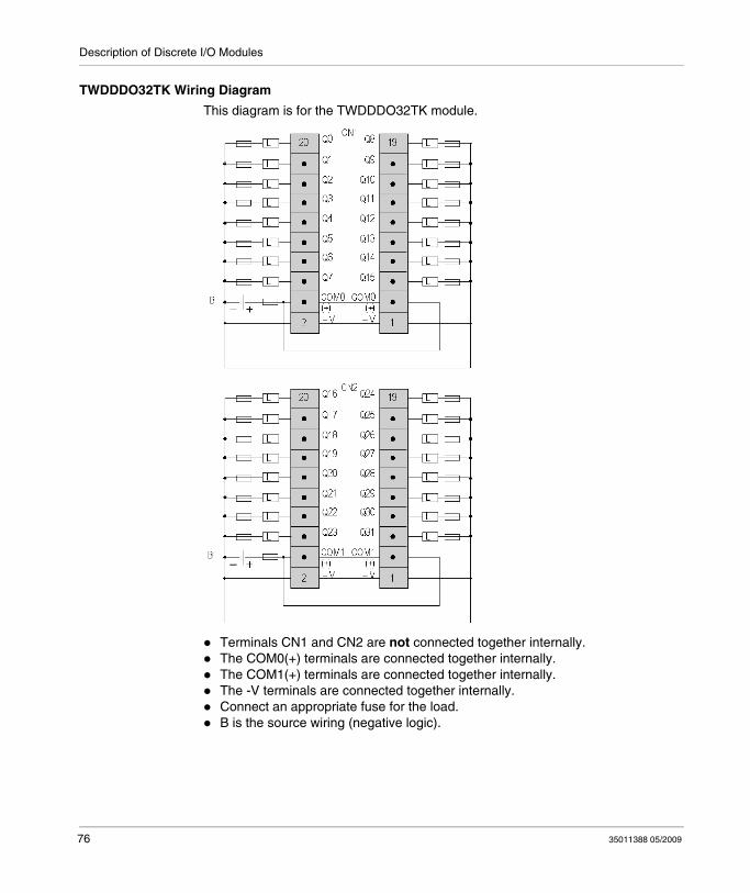
Terminals CN1 and CN2 are not connected together internally. The COM0(+) terminals are connected together internally.The COM1(+) terminals are connected together internally.The -V terminals are connected together internally.Connect an appropriate fuse for the load.B is the source wiring (negative logic).
76 35011388 05/2009

Description of Discrete I/O Modules
3.6 Specifications and Wiring Diagrams for Discrete Mixed I/O Modules
Introduction
This section provides general, electrical, I/O, and functional specifications, for Discrete Mixed I/O modules.
What's in this Section?
This section contains the following topics:
Topic Page
General Specifications for the Mixed I/O Modules 78
Electrical Specifications for the Mixed I/O Modules 79
I/O Specifications for the Mixed I/O Modules 80
Mixed I/O Module Wiring Diagrams 83
35011388 05/2009 77
Description of Discrete I/O Modules
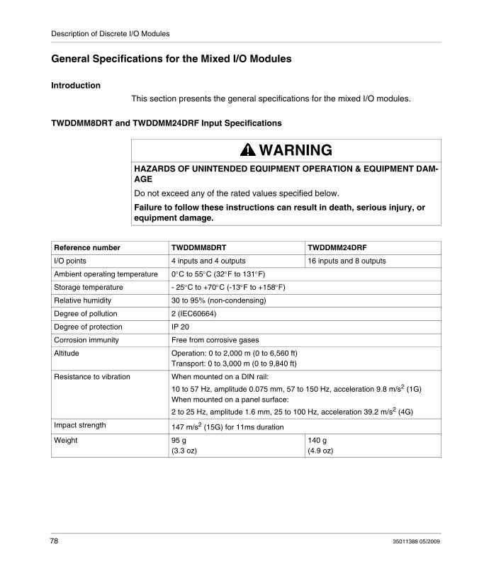
General Specifications for the Mixed I/O Modules
Introduction
This section presents the general specifications for the mixed I/O modules.
TWDDMM8DRT and TWDDMM24DRF Input Specifications
WARNINGHAZARDS OF UNINTENDED EQUIPMENT OPERATION & EQUIPMENT DAM-AGE
Do not exceed any of the rated values specified below.
Failure to follow these instructions can result in death, serious injury, or equipment damage.
Reference number TWDDMM8DRT TWDDMM24DRF
I/O points 4 inputs and 4 outputs 16 inputs and 8 outputs
Ambient operating temperature 0°C to 55°C (32°F to 131°F)
Storage temperature - 25°C to +70°C (-13°F to +158°F)
Relative humidity 30 to 95% (non-condensing)
Degree of pollution 2 (IEC60664)
Degree of protection IP 20
Corrosion immunity Free from corrosive gases
Altitude Operation: 0 to 2,000 m (0 to 6,560 ft)Transport: 0 to 3,000 m (0 to 9,840 ft)
Resistance to vibration When mounted on a DIN rail:
10 to 57 Hz, amplitude 0.075 mm, 57 to 150 Hz, acceleration 9.8 m/s2 (1G)When mounted on a panel surface:
2 to 25 Hz, amplitude 1.6 mm, 25 to 100 Hz, acceleration 39.2 m/s2 (4G)
Impact strength 147 m/s2 (15G) for 11ms duration
Weight 95 g(3.3 oz)
140 g(4.9 oz)
78 35011388 05/2009

Description of Discrete I/O Modules
Electrical Specifications for the Mixed I/O Modules
Introduction
This section presents the electrical specifications for the mixed I/O modules.
TWDDMM8DRT and TWDDMM24DRF Input Specifications
WARNINGHAZARDS OF UNINTENDED EQUIPMENT OPERATION & EQUIPMENT DAM-AGE
Do not exceed any of the rated values specified below.
Failure to follow these instructions can result in death, serious injury, or equipment damage.
Reference number TWDDMM8DRT TWDDMM24DRF
Connector insertion/removal durability 100 times minimum Not removable
Internal current draw -all I/O on
25 mA (5 VDC)20 mA (24 VDC)
65 mA (5 VDC)45 mA (24 VDC)
Internal current draw - all I/O off 5 mA (5 VDC)0 mA (24 VDC)
10 mA (5 VDC)0 mA (24 VDC)
35011388 05/2009 79
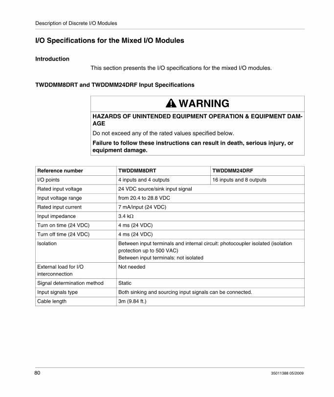
Description of Discrete I/O Modules
I/O Specifications for the Mixed I/O Modules
Introduction
This section presents the I/O specifications for the mixed I/O modules.
TWDDMM8DRT and TWDDMM24DRF Input Specifications
WARNINGHAZARDS OF UNINTENDED EQUIPMENT OPERATION & EQUIPMENT DAM-AGE
Do not exceed any of the rated values specified below.
Failure to follow these instructions can result in death, serious injury, or equipment damage.
Reference number TWDDMM8DRT TWDDMM24DRF
I/O points 4 inputs and 4 outputs 16 inputs and 8 outputs
Rated input voltage 24 VDC source/sink input signal
Input voltage range from 20.4 to 28.8 VDC
Rated input current 7 mA/input (24 VDC)
Input impedance 3.4 kΩ
Turn on time (24 VDC) 4 ms (24 VDC)
Turn off time (24 VDC) 4 ms (24 VDC)
Isolation Between input terminals and internal circuit: photocoupler isolated (isolation protection up to 500 VAC)Between input terminals: not isolated
External load for I/O interconnection
Not needed
Signal determination method Static
Input signals type Both sinking and sourcing input signals can be connected.
Cable length 3m (9.84 ft.)
80 35011388 05/2009
Description of Discrete I/O Modules
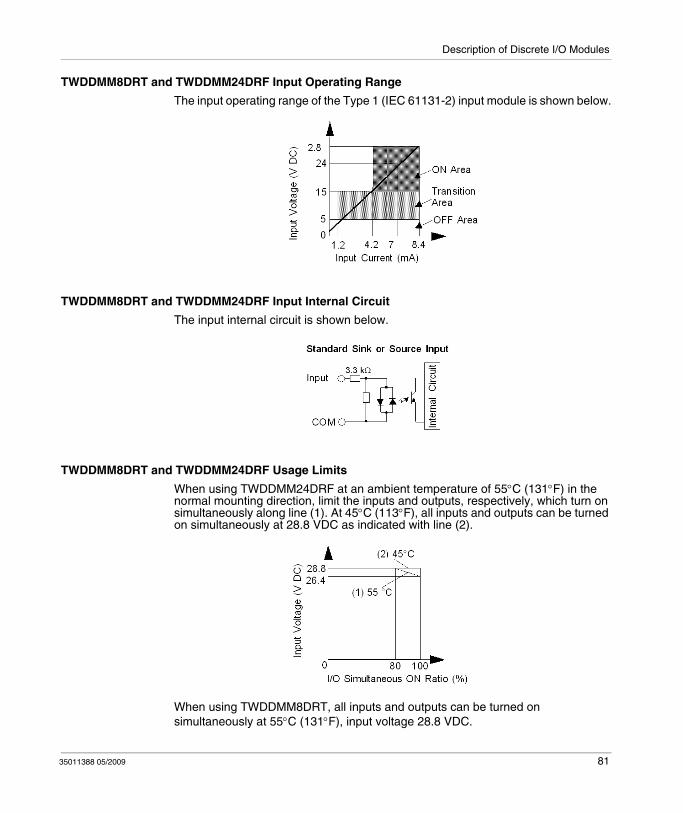
TWDDMM8DRT and TWDDMM24DRF Input Operating Range
The input operating range of the Type 1 (IEC 61131-2) input module is shown below.
TWDDMM8DRT and TWDDMM24DRF Input Internal Circuit
The input internal circuit is shown below.
TWDDMM8DRT and TWDDMM24DRF Usage Limits
When using TWDDMM24DRF at an ambient temperature of 55°C (131°F) in the normal mounting direction, limit the inputs and outputs, respectively, which turn on simultaneously along line (1). At 45°C (113°F), all inputs and outputs can be turned on simultaneously at 28.8 VDC as indicated with line (2).
When using TWDDMM8DRT, all inputs and outputs can be turned on simultaneously at 55°C (131°F), input voltage 28.8 VDC.
35011388 05/2009 81

Description of Discrete I/O Modules
TWDDMM8DRT and TWDDMM24DRF Output Specifications
TWDDMM8DRT and TWDDMM24DR Output Delay
The output delay is shown below.
Reference number TWDDMM8DRT TWDDMM24DRF
Output points and common lines 4 NO contacts in 1 common line 8 NO contacts in 2 common lines
Maximum load current 2 A per output7 A per common line
Minimum switching load 0.1 mA/0.1 VDC (reference value)
Initial contact resistance 30 mΩ maximum
Electrical life 100,000 operations minimum (rated resistive load 1,800 operations/h)
Mechanical life 20,000,000 operations minimum (no load 18,000 operations/h)
Rated load (resistive/inductive) 240 VAC/2 A, 30 VDC/2 A
Dielectric strength Between the output and ground terminals: 1500 VAC, 1 minuteBetween output terminal and internal circuit: 1500 VAC, 1 minuteBetween output groups: 1500 VAC, 1 minute
82 35011388 05/2009

Description of Discrete I/O Modules
Mixed I/O Module Wiring Diagrams
Introduction
This section shows examples of wiring diagrams for the mixed I/O modules. Symbols used in the following diagrams are explained in the glossary of symbols (see page 91) in the appendix.
NOTE: These diagrams are for external wiring only.
NOTE: The shaded boxes are markings on the discrete I/O modules. The I and Q numbers are the input and output points.
DANGERHAZARD OF ELECTRIC SHOCK, EXPLOSION OR ARC FLASH
Remove ALL power from ALL devices before connecting or disconnecting inputs or outputs to any terminal or installing or removing any hardware.Connect the grounding wire to a proper ground.
Failure to follow these instructions will result in death or serious injury.
WARNINGMALFUNCTION OF OUTPUTS
Use appropriate safety interlocks where personal and/or equipment hazards exist. Outputs can malfunction and remain ON or OFF.
Failure to follow these instructions can result in death, serious injury, or equipment damage.
35011388 05/2009 83
Description of Discrete I/O Modules
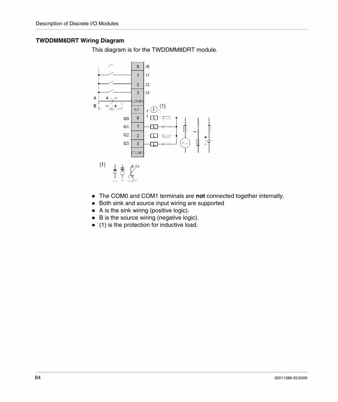
TWDDMM8DRT Wiring Diagram
This diagram is for the TWDDMM8DRT module.
The COM0 and COM1 terminals are not connected together internally.Both sink and source input wiring are supportedA is the sink wiring (positive logic).B is the source wiring (negative logic).(1) is the protection for inductive load.
84 35011388 05/2009
Description of Discrete I/O Modules
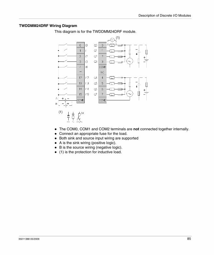
TWDDMM24DRF Wiring Diagram
This diagram is for the TWDDMM24DRF module.
The COM0, COM1 and COM2 terminals are not connected together internally.Connect an appropriate fuse for the load.Both sink and source input wiring are supportedA is the sink wiring (positive logic).B is the source wiring (negative logic).(1) is the protection for inductive load.
35011388 05/2009 85

Description of Discrete I/O Modules
86 35011388 05/2009
35011388 05/2009
Appendices
Introduction
This appendix provides information on system diagnostic using LED’s, operator display operation, troubleshooting, the DIN rail, common IEC symbols used in this manual, and agency compliance.
What's in this Appendix?
The appendix contains the following chapters:
Chapter Chapter Name Page
A The DIN Rail 89
B IEC Symbols 91
C Agency Compliance 93
35011388 05/2009 87

88 35011388 05/2009
35011388 05/2009
A
The DIN Rail
35011388 05/2009
The DIN Rail
The DIN Rail
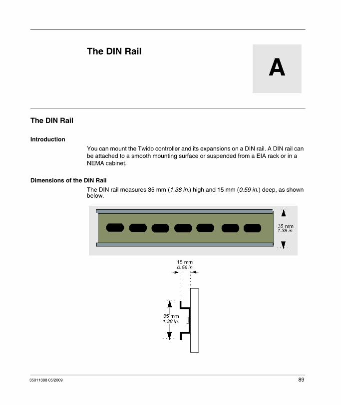
Introduction
You can mount the Twido controller and its expansions on a DIN rail. A DIN rail can be attached to a smooth mounting surface or suspended from a EIA rack or in a NEMA cabinet.
Dimensions of the DIN Rail
The DIN rail measures 35 mm (1.38 in.) high and 15 mm (0.59 in.) deep, as shown below.
89

The DIN Rail
Recommended Equipment
You can order the suitable DIN rail from Schneider Electric:
Rail depth Catalogue part number
15 mm (0.59 in.) AM1DE200
90 35011388 05/2009
35011388 05/2009
B
IEC Symbols
35011388 05/2009
IEC Symbols
Glossary of Symbols
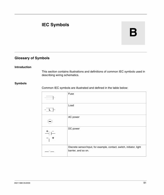
Introduction
This section contains illustrations and definitions of common IEC symbols used in describing wiring schematics.
Symbols
Common IEC symbols are illustrated and defined in the table below:
Fuse
Load
AC power
DC power
Discrete sensor/input, for example, contact, switch, initiator, light barrier, and so on.
91
IEC Symbols
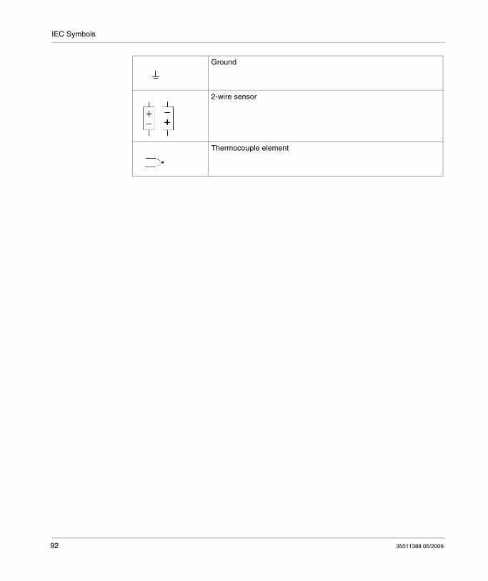
Ground
2-wire sensor
Thermocouple element
92 35011388 05/2009
35011388 05/2009
C
Agency Compliance
35011388 05/2009
Agency Compliance
Agency Requirements
Introduction
This section provides agency standards for the Twido products.
Standards
Twido controllers comply with the main national and international standards concerning electronic industrial control devices.
The following are specific controller requirements:
EN 61131-2 (IEC 61131-2)
UL 508
UL 1604 / CSA 213 Class I Division 2 Groups A, B, C, D
93

Agency Compliance
94 35011388 05/2009
Glossary
35011388 05/2009
Glossary
A
Analog potentiometerIt can be used to preset a value for an analog timer. All Modular controllers and Compact 10 and 16 I/O controllers have one analog potentiometer. The Compact 24 I/O controller has two:
Analog Voltage Input ConnectorConnects an analog voltage source of 0 through 10 VDC. The analog voltage is converted to a discrete value and is stored in a system word.
C
CANController Area Network: field bus originally developed for automobile applications which is now used in many sectors, from industrial to tertiary.
Cartridge ConnectorA connector to attach an optional memory cartridge or an RTC.
Catch InputVerify that you are receiving short input pulses (rising pulse of 40 μs or falling pulse of 150 μs minimum) from sensors without regard to the scan time.
35011388 05/2009 95
Glossary
CiACAN in Automation: international organization of users and manufacturers of CAN products.
COBCommunication OBject: transport unit on CAN bus. A COB is identified by a unique identifier, which is coded on 11 bits, [0, 2047]. A COB contains a maximum of 8 data bytes. The priority of a COB transmission is shown by its identifier - the weaker the identifier, the more priority the associated COB has.
Communication AdapterAn optional cartridge that can be attached to any Compact controller or Operator Display Expansion Module to provide an optional Serial Port 2.
Communication Expansion ModuleAn optional module that can be attached to any Modular controllers communications expansion bus to provide an optional Serial Port 2.
Controller status outputA special function. This function is used in circuits, external to the controller, to control the power supply to the output devices or the controller power supply.
E
EDSElectronic Data Sheet: description file for each CAN device (provided by the manufacturers).
ERR LEDAn LED that illuminates when a detected error is detected in the controller.
Expansion connectorA connector to attach expansion I/O modules.
Expansion Connector CoverA cover to protect the expansion connector.
96 35011388 05/2009
Glossary
Expansion I/O ModuleEither a discrete or analog module that adds additional I/O to the base controller.
F
Fast CountingA special function, it is available as a single up counter and single down counter. These functions enable up counting or down counting of pulses (rising edges)on a discrete I/O. Compact controllers can be equipped with three fast counters. Modular controllers can have two fast counters.
Free WireThe end of a discrete I/O cable whose wires do not have a connector. This scheme provides connectivity from Modular I/O to discrete I/O points.
I
I/OInput/Output.
I/O terminalsTerminals on all Modular controllers and expansion I/O modules used to connect input and output signals. The input terminals accept both sink and source DC input signals. The output terminals are either transistor source or sink or relay contacts.
IN LEDAn LED that illuminates when a corresponding input is on. All modules have IN LEDs.
Input FilterA special function that rejects input noises. This function is useful for addressing input noises and chatter in limit switches. All inputs provide a level of input filtering using the hardware. Additional filtering using the software is also configurable through TwidoSuite.
35011388 05/2009 97
Glossary
Input SimulatorsAn optional accessory for Compact controllers that is used for debugging. It can simulate input sensors to test application logic.
Input terminalsTerminals on the top of all Compact controllers used to connect input signals from input devices such as sensors, push buttons, and limit switches. The input terminals accept both sink and source DC input signals.
L
Latching inputA special function. This function is used to memorize any pulse with a duration less than the controller scan time. When a pulse is shorter than one scan and has a value greater than or equal to 100 μs, the controller latches the pulse, which is then updated in the next scan.
M
Memory CartridgeAn optional cartridge available in two sizes: 32 KB and 64 KB (64 KB not available on Compact). It can be added to any controller for removable backup of applications or to load an application, if certain conditions exist. The 64 KB cartridge is also used to increase program memory.
Modbus Master ModeAllows the controller to initiate a Modbus query transmission, with a response expected from a Modbus slave.
Modbus Slave ModeAllows the controller to respond to Modbus queries from a Modbus master and is the default communications mode if no communication is configured.
98 35011388 05/2009
Glossary
O
Operator display expansion moduleAn optional module that can be attached to any Modular controller to display program information.
Operator display moduleAn optional module that can be attached to any Compact controller to display program information.
OUT LEDAn LED that illuminates when a corresponding output is on. All modules have OUT LEDs.
Output terminalsTerminals on the bottom of all Compact controllers used to connect output signals from output devices such as electromechanical relays and solenoid valves. The internal output relay contact is rated up to 240 VAC/2A or 30 VDC/2A.
P
PLSA special function. This user-defined function block generates a signal on output %Q0.0.0 or %Q0.0.1. This signal has a variable period but has a constant duty cycle, or on to off ratio of 50% of the period.
Power Supply TerminalsThe power supply is connected to these terminals to provide power to the controller. The power voltage for a Compact controller is 100-240 VAC and 24 VDC for a Modular controller.
PWMA special function. This user-defined function block generates a signal on output %Q0.0.0 or %Q0.0.1. This signal has a constant period with the possibility of varying the duty cycle, or on to off ratio.
35011388 05/2009 99
Glossary
PWR LEDAn LED that illuminates when power is supplied to the controller.
R
Removable CoverA cover on all Compact controllers that can be removed to install an optional Operator Display.
RTCReal Time Clock.
RTDTemperature detector of type PT100, PT1000 etc. Resistor Temperature Detector.
RUN LEDAn LED that illuminates when the controller is executing a program.
S
Sensor power terminalsSupplies power to the sensors (24 VDC, 400 mA for -40DRF compact controllers and 250 mA for all other controllers). Output terminals are only intended for input devices and not be used as a source for driving external loads.
Serial Port 1An EIA RS-485 connector used to download and monitor the controller operation using TwidoSuite.
Serial port 2An optional port that can be configured as either EIA RS-232 or EIA RS-485.
STAT LEDAn LED that blinks on and off to indicate a specific status of the user program.
100 35011388 05/2009
Glossary
T
Terminal coverA cover on all Compact controllers to protect the input and output terminals.
V
Very Fast CountingA special function available as an up/down counter, an up/down 2-phase counter, a single up counter, a single down counter, and frequency meter. The counter functions enable counting of pulses from 0 to 65,535 in single-word mode and from 0 to 4,294,967,295 in double-word mode. The frequency meter function measures the frequency of a periodic signal in Hz.
35011388 05/2009 101

Glossary
102 35011388 05/2009

Index
35011388 05/2009
CBA
IndexAAgency requirements, 93
BBases
Assembling an expansion I/O module, 23Disassembling an expansion I/O module, 25Minimum clearance, 26Mounting positions, 21
CCables, 13Compact
Minimum clearance, 26
DDimensions
Discrete I/O modules, 29, 30, 30, 31, 31DIN rail
15 mm AM1DE200 rail, 90Discrete I/O
Input internal circuit, 44Operating range, 43
Discrete I/O cables, 13Discrete I/O modules
Dimensions, 29, 30, 30, 31, 31Discrete I/O Modules
Features, 14
35011388 05/2009
Discrete I/O modulesInstalling on a DIN rail, 34Mounting hole layout, 33Overview, 39Parts description, 40Removing from a DIN rail, 36Specifications, 12Transistor sink output contact, 69Transistor source output contact, 69
Discrete Input modulesI/O usage limits, 52Operating range, 58Wiring diagrams, 53
Discrete lnput modulesInternal circuit, 51
EExpansion I/O modules
Assembling to a base, 23Disassembling from a base, 25
II/O modules
Discrete, 12Expansion modules, 12
I/O usage limitsDiscrete I/O modules, 81Discrete Input modules, 52
IEC symbols, 91Input I/O modules, 14
103

Index
Input internal circuitDiscrete I/O modules, 81Discrete I/O Modules, 44
InstallationRead before starting, 19
Installation preparation, 20Installing on a DIN rail, 34Internal circuit
Discrete Input modules, 51
MMain Features, 14Minimum clearance
Bases, 26Compact, 26Modular, 27
Mixed I/O modules, 14I/O usage limits, 81Input internal circuit, 81Operating range, 81Output delay, 82Wiring diagrams, 83
ModularMinimum clearance, 27
Mounting hole layoutDiscrete I/O modules, 33
OOperating range
Discrete I/O modules, 81Discrete I/O Modules, 43Discrete Input modules, 58
Output delayDiscrete I/O modules, 82Relay Output modules, 63
Output I/O modules, 14Overview
Discrete I/O module, 39
PParts description
Discrete I/O modules, 40
104
RRead before starting, 20Relay output contact
Relay Output modules, 61Relay Output modules
Relay output contact, 61Wiring diagrams, 64
Relay utputO modulesOutput delay, 63
SSpecifications
Discrete I/O modules, 12Standards, 93Starting, 19, 20Symbols, 91
TTransistor Output modules
Wiring diagrams, 72Transistor sink output contact
Discrete I/O modules, 69Transistor source output contact
Discrete I/O modules, 69
WWiring diagrams
Discrete I/O modules, 72, 83Discrete Input modules, 53Relay Output modules, 64
35011388 05/2009