DISCONNECT SWITCHES OPEN TYPE HS1-ML2/3 MZ 43 058 HS3-ML3 MZ 43 068 Extension shafts and shaft...
6
22 Picture: application EV, red/yellow not displayed: application EVS, black/silver Picture: application 1550/1850, red/yellow not displayed: application 1551/1851, black/grey Picture: application 0288-EVS, black/silver not displayed: application 0288-EV, red/yellow Picture: application 1581/1881, black/grey not displayed: application 1580/1880, red/yellow 4-hole mounting with lockout handle for 1 or 2 padlocks with shackle diameter up to 5 mm, ML-switches with terminal cover MAIN SWITCHES EMERGENCY-OFF SWITCHES IP 55 DISCONNECT SWITCHES - OPEN TYPE ML ON OFF ON OFF 1 5 3 5 1 3 /6. A 6 4 2 4 6 2 Contact diagram 3pole 4-hole mounting with lockout handle for 3 padlocks with shackle diameter up to 9 mm, ML-switches with terminal cover IP 65 ML ON OFF ON OFF 1 5 3 5 1 3 /6. A 6 4 2 4 6 2 Contact diagram 3pole Door coupling and door interlock with lockout handle for 1 or 2 padlocks with shackle diameter up to 5 mm, ML-switches with terminal cover IP 55 ML ON OFF ON OFF 1 5 3 5 1 3 /6. A 6 4 2 4 6 2 Contact diagram 3pole Door coupling and door interlock with lockout handle for 3 padlocks with shackle diameter up to 9 mm, ML-switches with terminal cover IP 55 ML ON OFF ON OFF 1 5 3 5 1 3 /6. A 6 4 2 4 6 2 Contact diagram 3pole
Transcript of DISCONNECT SWITCHES OPEN TYPE HS1-ML2/3 MZ 43 058 HS3-ML3 MZ 43 068 Extension shafts and shaft...

22
Picture: application EV, red/yellownot displayed: application EVS, black/silver
Picture: application 1550/1850, red/yellownot displayed: application 1551/1851, black/grey
Picture: application 0288-EVS, black/silvernot displayed: application 0288-EV, red/yellow
Picture: application 1581/1881, black/greynot displayed: application 1580/1880, red/yellow
4-hole mounting with lockout handle for1 or 2 padlocks
with shackle diameter up to 5 mm, ML-switches with terminal cover
MAIN SWITCHES EMERGENCY-OFF SWITCHES
IP 55
DISCONNECT SWITCHES - OPEN TYPE
ML
ON
OFF
ON
OFF
1 535 1 3 /6. A
6424 62
Contact diagram3pole
4-hole mounting with lockout handle for3 padlocks
with shackle diameter up to 9 mm,ML-switches with terminal cover
IP 65
ML
ON
OFF
ON
OFF
1 535 1 3 /6. A
6424 62
Contact diagram3pole
Door coupling and door interlock withlockout handle for 1 or 2 padlocks
with shackle diameter up to 5 mm,ML-switches with terminal cover
IP 55
ML
ON
OFF
ON
OFF
1 535 1 3 /6. A
6424 62
Contact diagram3pole
Door coupling and door interlockwith lockout handle for 3 padlocks
with shackle diameter up to 9 mm,ML-switches with terminal cover
IP 55
ML
ON
OFF
ON
OFF
1 535 1 3 /6. A
6424 62
Contact diagram3pole

23
acc. to IEC 60947-3, EN 60947-3 (DIN VDE 0660 Teil 107), UL and CSA
BASE MOUNTING V
Terminal screws are accessible from the front
with screw and snap-on fixing on standard rail 35 mm (DIN EN 50022). Series 104 with screw fixing. Snap-on fixing on request.
FRONT MOUNTING E
Terminal screws are accessible from the rear
Series Rated uninter- Making/breaking 3 x 400 V Handle Front plate Type Order no.rupted current capacity
Ith AC-3 AC-23A kW kW
104 20 5,5 7,5 rd ye A 104/6.0200-EV MZ 10 041ML1 25 7,5 11 rd ye ML1-025-E-0200-EV-HS MZ 33 001ML1 40 11 15 rd ye ML1-040-E-0200-EV-HS MZ 35 001104 20 5,5 7,5 bl si A 104/6.0200-EVS MZ 10 042ML1 25 7,5 11 bl si ML1-025-E-0200-EVS-HS MZ 33 029ML1 40 11 15 bl si ML1-040-E-0200-EVS-HS MZ 35 029
Series Rated uninter- Making/breaking 3 x 400 V Handle Front plate Type Order no.rupted current capacity
Ith AC-3 AC-23A kW kW
104 20 5,5 7,5 rd ye A 104/6.1550 MZ 10 085ML1 25 7,5 11 rd ye ML1-025-E-1550-HS MZ 33 002ML1 40 11 15 rd ye ML1-040-E-1550-HS MZ 35 002ML2 63 22 30 rd ye ML2-063-E-1850-HS MZ 37 002ML2 80 30 37 rd ye ML2-080-E-1850-HS MZ 39 002ML3 125 37 45 rd ye ML3-125-E-1850-HS MZ 41 002104 20 5,5 7,5 bl gr A 104/6.1551 MZ 10 086ML1 25 7,5 11 bl gr ML1-025-E-1551-HS MZ 33 030ML1 40 11 15 bl gr ML1-040-E-1551-HS MZ 35 030ML2 63 22 30 bl gr ML2-063-E-1851-HS MZ 37 030ML2 80 30 37 bl gr ML2-080-E-1851-HS MZ 39 030ML3 125 37 45 bl gr ML3-125-E-1851-HS MZ 41 030
Series Rated uninter- Making/breaking 3 x 400 V Handle Front plate Type Order no.rupted current capacity
Ith AC-3 AC-23A kW kW
104 20 5,5 7,5 rd ye A 104/6.1580 MZ 10 097ML1 25 7,5 11 rd ye ML1-025-V-1580-HS MZ 33 016ML1 40 11 15 rd ye ML1-040-V-1580-HS MZ 35 016ML2 63 22 30 rd ye ML2-063-V-1880-HS MZ 37 016ML2 80 30 37 rd ye ML2-080-V-1880-HS MZ 39 016ML3 125 37 45 rd ye ML3-125-V-1880-HS MZ 41 016104 20 5,5 7,5 bl gr A 104/6.1581 MZ 10 098ML1 25 7,5 11 bl gr ML1-025-V-1581-HS MZ 33 044ML1 40 11 15 bl gr ML1-040-V-1581-HS MZ 35 044ML2 63 22 30 bl gr ML2-063-V-1881-HS MZ 37 044ML2 80 30 37 bl gr ML2-080-V-1881-HS MZ 39 044ML3 125 37 45 bl gr ML3-125-V-1881-HS MZ 41 044
Series Rated uninter- Making/breaking 3 x 400 V Handle Front plate Type Order no.rupted current capacity
Ith AC-3 AC-23A kW kW
104 20 5,5 7,5 rd ye A 104/6.0288-EV MZ 10 053ML1 25 7,5 11 rd ye ML1-025-V-0288-EV-HS MZ 33 015ML1 40 11 15 rd ye ML1-040-V-0288-EV-HS MZ 35 015104 20 5,5 7,5 bl si A 104/6.0288-EVS MZ 10 054ML1 25 7,5 11 bl si ML1-025-V-0288-EVS-HS MZ 33 043ML1 40 11 15 bl si ML1-040-V-0288-EVS-HS MZ 35 043
Dimensions illustration/Dimensions see page 44

24
Distribution board mounting
with screw and snap on fixing on standard rail 35 mm(DIN EN 50022)Terminal screws are accessible from the front
Handle blackFront plate grey
SWITCH-DISCONNECTOREMERGENCY-OFF SWITCHESMAIN SWITCH
IP 30
DISCONNECT SWITCHES - OPEN TYPE
ML
ON
OFF
ON
OFF
1 535 1 3 /6. A
6424 62
Contact diagram3pole
Distribution board mounting with lockout handlefor 1 or 2 padlocks
Shackle diameter up to 5 mm, with screw and snap on fixing on standardrail 35 mm (DIN EN 50022), terminal cover with standard cut-out 35 mmTerminal screws are accessible from the front
Handle redFront plate yellow
IP 30
ML
ON
OFF
ON
OFF
1 535 1 3 /6. A
6424 62
Contact diagram3pole
Distribution board mounting with lockout handlefor 1 or 2 padlocks
Shackle diameter up to 5 mm, with screw and snap on fixing on stan-dard rail 35 mm (DIN EN 50022),terminal cover with standard cut-out 35 mmTerminal screws are accessible from the front
Handle blackFront plate grey
IP 30
ML
ON
OFF
ON
OFF
1 535 1 3 /6. A
6424 62
Contact diagram3pole

25
acc. to IEC 60947-3, EN 60947-3 (DIN VDE 0660 part 107), UL 508 and CSA 22.2
DISTRIBUTION BOARD MOUNTING
Series Rated uninter- Making/breaking 3 x 400 V Type Order no.rupted current capacity
Ith AC-3 AC-23A kW kW
104 20 5,5 7,5 A 104/6.9121 MZ 10 552ML1 25 7,5 11 ML1-025-V-9121 MZ 33 058ML1 40 11 15 ML1-040-V-9121 MZ 35 058ML2 63 22 30 ML2-063-V-9131 MZ 37 170ML2 80 30 37 ML2-080-V-9131 MZ 39 170ML3 125 37 48 ML3-125-V-9141 MZ 41 170
Series Rated uninter- Making/breaking 3 x 400 V Type Order no.rupted current capacity
Ith AC-3 AC-23A kW kW
104 20 5,5 7,5 A 104/6.9121-EV MZ 10 556ML1 25 7,5 11 ML1-025-V-9121-EV-HS MZ 33 059ML1 40 11 15 ML1-040-V-9121-EV-HS MZ 35 059ML2 63 72 30 ML2-063-V-9131-EV-HS MZ 37 171ML2 80 30 37 ML2-080-V-9131-EV-HS MZ 39 171ML3 125 37 45 ML3-125-V-9141-EV-HS MZ 41 171
Series Rated uninter- Making/breaking 3 x 400 V Type Order no.rupted current capacity
Ith AC-3 AC-23A kW kW
104 20 5,5 7,5 A 104/6.9121-EVS MZ 10 560ML1 25 7,5 11 ML1-025-V-9121-EVS-HS MZ 33 060ML1 40 11 15 ML1-040-V-9121-EVS-HS MZ 35 060ML2 63 22 30 ML2-063-V-9131-EVS-HS MZ 37 172ML2 80 30 37 ML2-080-V-9131-EVS-HS MZ 39 172ML3 125 37 45 ML3-125-V-9141-EVS-HS MZ 41 172
Dimensions illustration/Dimensions see page 45
26
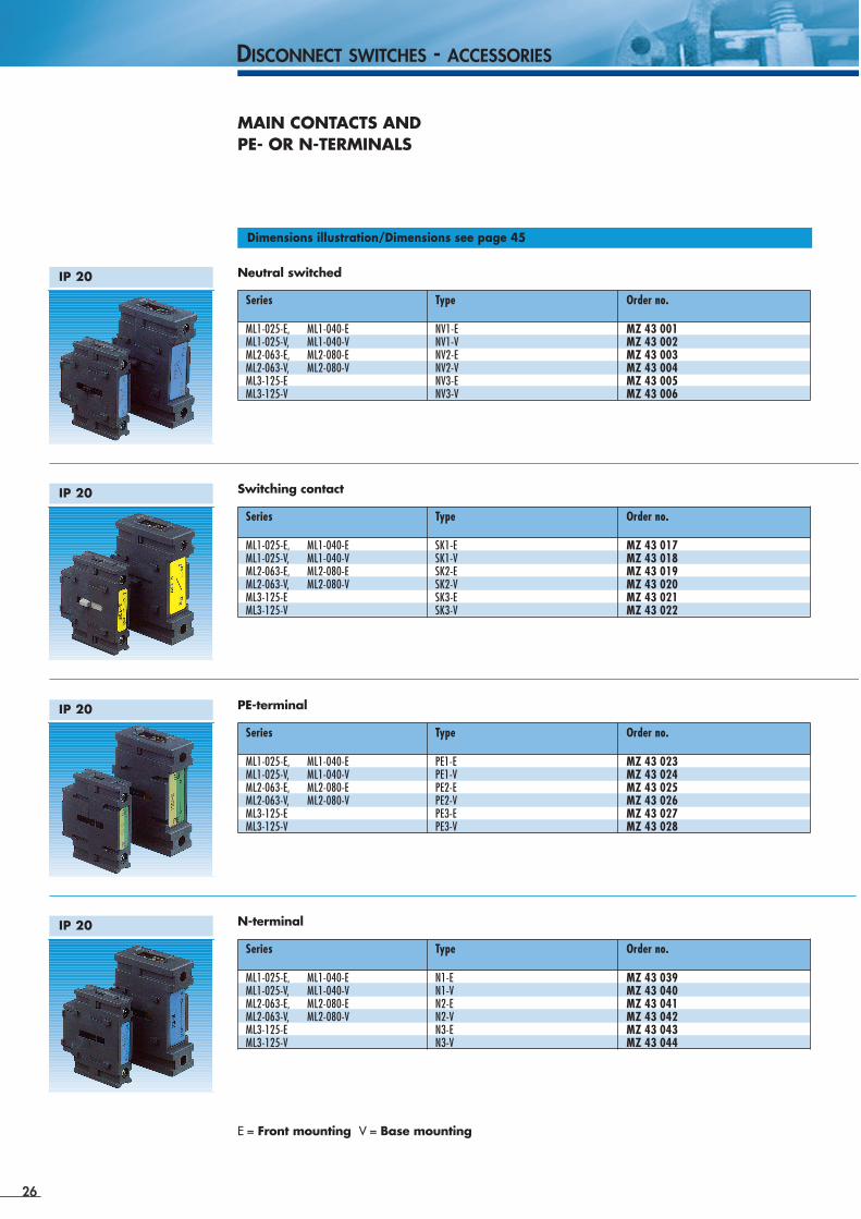
Neutral switched
MAIN CONTACTS AND PE- OR N-TERMINALS
IP 20
DISCONNECT SWITCHES - ACCESSORIES
Switching contactIP 20
PE-terminalIP 20
N-terminal
E = Front mounting V = Base mounting
IP 20
Series Type Order no.
ML1-025-E, ML1-040-E NV1-E MZ 43 001ML1-025-V, ML1-040-V NV1-V MZ 43 002ML2-063-E, ML2-080-E NV2-E MZ 43 003ML2-063-V, ML2-080-V NV2-V MZ 43 004ML3-125-E NV3-E MZ 43 005ML3-125-V NV3-V MZ 43 006
Dimensions illustration/Dimensions see page 45
Series Type Order no.
ML1-025-E, ML1-040-E SK1-E MZ 43 017ML1-025-V, ML1-040-V SK1-V MZ 43 018ML2-063-E, ML2-080-E SK2-E MZ 43 019ML2-063-V, ML2-080-V SK2-V MZ 43 020ML3-125-E SK3-E MZ 43 021ML3-125-V SK3-V MZ 43 022
Series Type Order no.
ML1-025-E, ML1-040-E PE1-E MZ 43 023ML1-025-V, ML1-040-V PE1-V MZ 43 024ML2-063-E, ML2-080-E PE2-E MZ 43 025ML2-063-V, ML2-080-V PE2-V MZ 43 026ML3-125-E PE3-E MZ 43 027ML3-125-V PE3-V MZ 43 028
Series Type Order no.
ML1-025-E, ML1-040-E N1-E MZ 43 039ML1-025-V, ML1-040-V N1-V MZ 43 040ML2-063-E, ML2-080-E N2-E MZ 43 041ML2-063-V, ML2-080-V N2-V MZ 43 042ML3-125-E N3-E MZ 43 043ML3-125-V N3-V MZ 43 044
27
acc. to IEC 60947-3, EN 60947-3 (DIN VDE 0660 part 107), UL508 and CSA 22.2
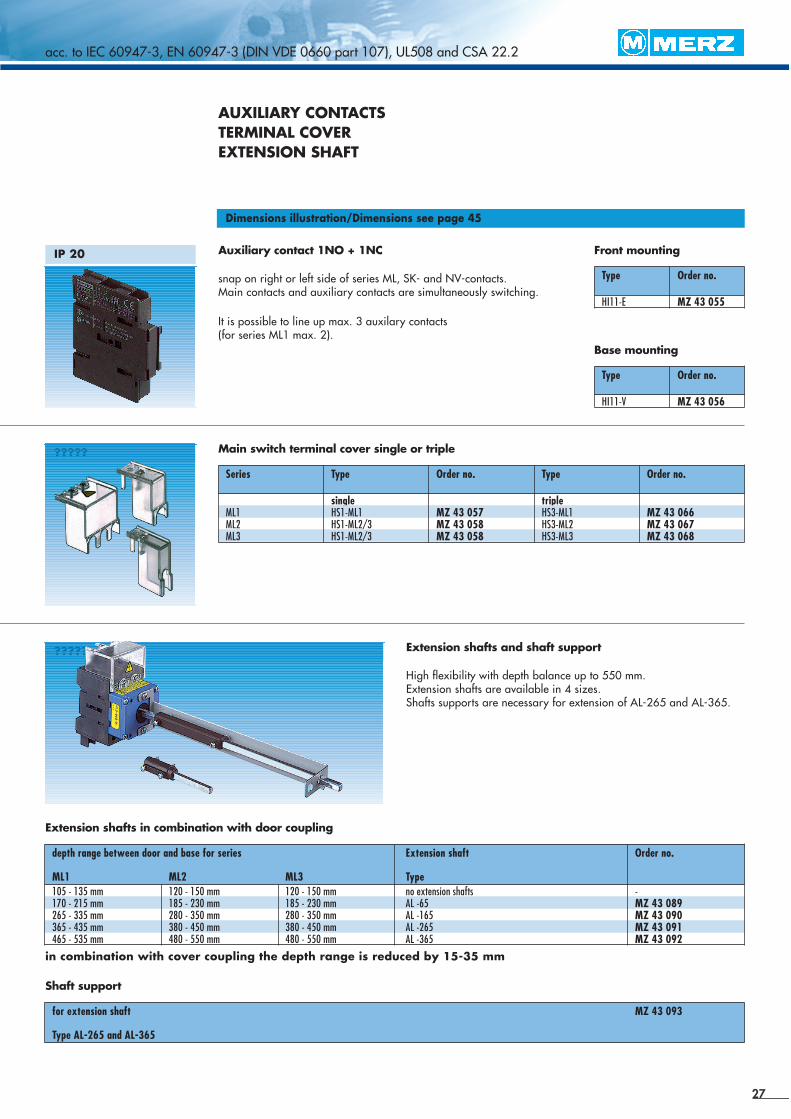
AUXILIARY CONTACTSTERMINAL COVEREXTENSION SHAFT
Extension shafts in combination with door coupling
Dimensions illustration/Dimensions see page 45
Auxiliary contact 1NO + 1NC
snap on right or left side of series ML, SK- and NV-contacts. Main contacts and auxiliary contacts are simultaneously switching.
It is possible to line up max. 3 auxilary contacts(for series ML1 max. 2).
Front mountingIP 20
Type Order no.
HI11-E MZ 43 055
Base mounting
Type Order no.
HI11-V MZ 43 056
Main switch terminal cover single or triple?????
Series Type Order no. Type Order no.
single tripleML1 HS1-ML1 MZ 43 057 HS3-ML1 MZ 43 066ML2 HS1-ML2/3 MZ 43 058 HS3-ML2 MZ 43 067ML3 HS1-ML2/3 MZ 43 058 HS3-ML3 MZ 43 068
Extension shafts and shaft support
High flexibility with depth balance up to 550 mm.Extension shafts are available in 4 sizes. Shafts supports are necessary for extension of AL-265 and AL-365.
?????
depth range between door and base for series Extension shaft Order no.
ML1 ML2 ML3 Type105 - 135 mm 120 - 150 mm 120 - 150 mm no extension shafts -170 - 215 mm 185 - 230 mm 185 - 230 mm AL -65 MZ 43 089265 - 335 mm 280 - 350 mm 280 - 350 mm AL -165 MZ 43 090365 - 435 mm 380 - 450 mm 380 - 450 mm AL -265 MZ 43 091465 - 535 mm 480 - 550 mm 480 - 550 mm AL -365 MZ 43 092
Shaft support
for extension shaft MZ 43 093
Type AL-265 and AL-365
in combination with cover coupling the depth range is reduced by 15-35 mm