Disconnect Switch and Circuit Breaker Mechanism ......Technical Data Disconnect Switch and Circuit...
26
Technical Data Disconnect Switch and Circuit Breaker Mechanism Specifications Bulletin Number 1494 Topic Page Summary of Changes 2 Additional Resources 2 Specifications Bulletin 1494U Disconnect Switches 3 Bulletin 1494C, 1494F, 1494G, 1494R, 1494V Disconnect Switches 4 Bulletin 1494H, 1494HL Disconnect Switches 5 Bulletin 1494D, 1494V Circuit Breakers 6 Approximate Dimensions Bulletin 1494U Disconnect Switch and Fuse Block, 30…60 A 7 Bulletin 1494U Disconnect Switch and Fuse Block, 100 A 8 Bulletin 1494U Handle with Support Bracket 9 Bulletin 1494V 10 Bulletin 1494C 11 Bulletin 1494F Disconnect Switches 12 Bulletin 1494F Disconnect Switches Vault Hardware Latching (Enclosures that are not pre-drilled) 13 Bulletin 1494R Disconnect Switches 14 Bulletin 1494V 15 Bulletin 1494D Circuit Breakers 16 Bulletin 1494G, 1494GX, 1494GY Enclosed Disconnect Safety Switches Type 3R/4/12 (Enclosure Code “F”) Painted Metal Enclosures 17 Bulletin 1494G, 1494GX, 1494GY Enclosed Disconnect Safety Switches Type 4/4X (Enclosure Code “C”) Stainless Steel Enclosures 18 Bulletin 1494G Safety Switch — Hazardous Locations 19 Bulletin 1494H Heavy-Duty Safety Switches Type 1 (Enclosure Code “A”) General-Purpose Painted Metal Enclosures 20 Bulletin 1494H Heavy-Duty Safety Switches Type 3R (Enclosure Code “N”) Rain-Proof Painted Metal Enclosures 21 Bulletin 1494H Heavy-Duty Safety Switches Type 12 (Enclosure Code "F") Dust-Tight Painted Metal Enclosures 22 Bulletin 1494HL General Duty Safety Switches Type 1 (Enclosure Code “A”) General-Purpose Painted Metal Enclosures 23
Transcript of Disconnect Switch and Circuit Breaker Mechanism ......Technical Data Disconnect Switch and Circuit...

Technical Data
Disconnect Switch and Circuit Breaker Mechanism SpecificationsBulletin Number 1494
Topic Page
Summary of Changes 2
Additional Resources 2
Specifications
Bulletin 1494U Disconnect Switches 3
Bulletin 1494C, 1494F, 1494G, 1494R, 1494V Disconnect Switches 4
Bulletin 1494H, 1494HL Disconnect Switches 5
Bulletin 1494D, 1494V Circuit Breakers 6
Approximate Dimensions
Bulletin 1494U Disconnect Switch and Fuse Block, 30…60 A 7
Bulletin 1494U Disconnect Switch and Fuse Block, 100 A 8
Bulletin 1494U Handle with Support Bracket 9
Bulletin 1494V 10
Bulletin 1494C 11
Bulletin 1494F Disconnect Switches 12
Bulletin 1494F Disconnect Switches Vault Hardware Latching (Enclosures that are not pre-drilled) 13
Bulletin 1494R Disconnect Switches 14
Bulletin 1494V 15
Bulletin 1494D Circuit Breakers 16
Bulletin 1494G, 1494GX, 1494GY Enclosed Disconnect Safety Switches Type 3R/4/12 (Enclosure Code “F”) Painted Metal Enclosures 17
Bulletin 1494G, 1494GX, 1494GY Enclosed Disconnect Safety Switches Type 4/4X (Enclosure Code “C”) Stainless Steel Enclosures 18
Bulletin 1494G Safety Switch — Hazardous Locations 19
Bulletin 1494H Heavy-Duty Safety Switches Type 1 (Enclosure Code “A”) General-Purpose Painted Metal Enclosures 20
Bulletin 1494H Heavy-Duty Safety Switches Type 3R (Enclosure Code “N”) Rain-Proof Painted Metal Enclosures 21
Bulletin 1494H Heavy-Duty Safety Switches Type 12 (Enclosure Code "F") Dust-Tight Painted Metal Enclosures 22
Bulletin 1494HL General Duty Safety Switches Type 1 (Enclosure Code “A”) General-Purpose Painted Metal Enclosures 23
Disconnect Switch and Circuit Breaker Mechanism Specifications
Summary of Changes
This publication contains new and updated information as indicated in the following table.
Additional Resources
These documents contain additional information concerning related products from Rockwell Automation®.
You can view or download publications at http://www.rockwellautomation.com/global/literature-library/overview.page. To order paper copies of technical documentation, contact your local Allen-Bradley® distributor or Rockwell Automation sales representative.
Topic Page
Updated 1494U specifications 3
Resource Description
Industrial Automation Wiring and Grounding Guidelines, publication 1770-4.1 Provides general guidelines for installing a Rockwell Automation industrial system.
Product Certifications website, http://www.rockwellautomation.com/global/certification/overview.page Provides declarations of conformity, certificates, and other certification details.
2 Rockwell Automation Publication 1494-TD001E-EN-P - February 2016

Disconnect Switch and Circuit Breaker Mechanism Specifications
Bulletin 1494U Disconnect Switches Disconnect Switch Electrical Ratings
Switch Size 30 A 60 A 100 ARated Insulation Voltage (UL) IEC - Ui (600) 1000V
RatingsUL/CSA/NEMA
Hp
230V/60 Hz460V/60 Hz575V/60 Hz
7.51520
153050
306075
600V DC 15 30 50
ContinuousCurrent, Ithe
600V AC600V DC 30 60 100
RatingsIEC Applications
Maximum kW(AC23)
220V/50 Hz440V/50 Hz550V/50 Hz
5.51115
112237
224555
Auxiliary Contact Electrical Ratings
Standard Contact 1 N.O. or 1 N.C.NEMA/EEMAC A600, Q600
IEC AC 15, DC 13 to IEC/EN60947-5-1 and UL 508, 17V, 5 mA minimum
Low Level Contact 1 N.O. or 1 N.C.NEMA/EEMAC C300, R150
IEC AC 15, DC 13 to IEC/EN60947-5-1 and UL 508, 5V, 1 mA minimum
Electrical Interlock RatingsStandard Contact 2 N.O. NEMA/EEMAC 10 A: 250V AC, 0.3 A: 250V DC
Mechanical
Degree of Protection Operating handlesNon-metallic Type 1, 3R, 4, 4X, 12
Painted Type 1, 3R, 4, 12Stainless steel Type 4, 4X
Mechanical Life (Typical) 10 000 operations (30…100 A)
Switching Frequency (operations/hr) 30, 60, and 100 A sizes — 300 maximum
Environmental
Ambient Temperature
Open -20…+60 °C (-4…+140 °F)
Enclosed -20…+40 °C (-4…+104 °F)
Storage -40…+65 °C (-40…+149 °F)
Altitude (per IEC 947-1) 2000 m
Relative Humidity (per IEC 947-1) 90% at 20 °C (68 °F) and 50% at 40 °C (104 °F)
Design Specification/Test RequirementsDielectric Strength 2200V for 1 minute
Electrical Life 6000 operations at rated current
Short Circuit Withstand Capability10 000 A, 600V AC/DC: unfused or with Class H fuses
10 000 A, 600V DC: with Class J or Class R fuses200 000 A, 600V AC: with Class J or Class R fuses
ConstructionSwitch Body Material Glass-filled thermoplastic
All wire rated 75 °C (167 °F) or higher must be sized per the local Electric Code for 75 °C (167 °F) wire.
Conductor Size and Lug Connectors
Single port, aluminum lug 30…60 A(1) #14…2 AWG, copper - aluminum
(2) #14…10 AWG, copper(2) #12…10 AWG, aluminum
Single port, aluminum lug 100 A(2) #12…4 AWG, copper-aluminum
(1) #14…1/0 AWG, copper(1) #12…1/0 AWG, aluminum
Multi-port, aluminum lug 30…100 A(1) #14…4 AWG, copper
(1) #12…4 AWG, aluminum(2) #10 AWG, copper-aluminum
Single port, copper lug 30…60 A(1) #14…4 AWG, copper(2) #14…8 AWG, copper
(4) #16 AWG, copper
Line Terminal AdapterSingle port, copper lug 30…100 A (1) #14…8 AWG, copper
Line Terminal AdapterSingle port, copper lug 100 A (1) #8…1/0 AWG, copper
Recommended Torque 30 A60 A100 A
Conductor into Lug45 lb•in45 lb•in50 lb•in
Lug to Terminal40…60 lb•in40…60 lb•in40…60 lb•in
Switches, Mechanisms, and Accessory Kits Zinc-plated steel, RoHS Compliant finish
Rockwell Automation Publication 1494-TD001E-EN-P - February 2016 3
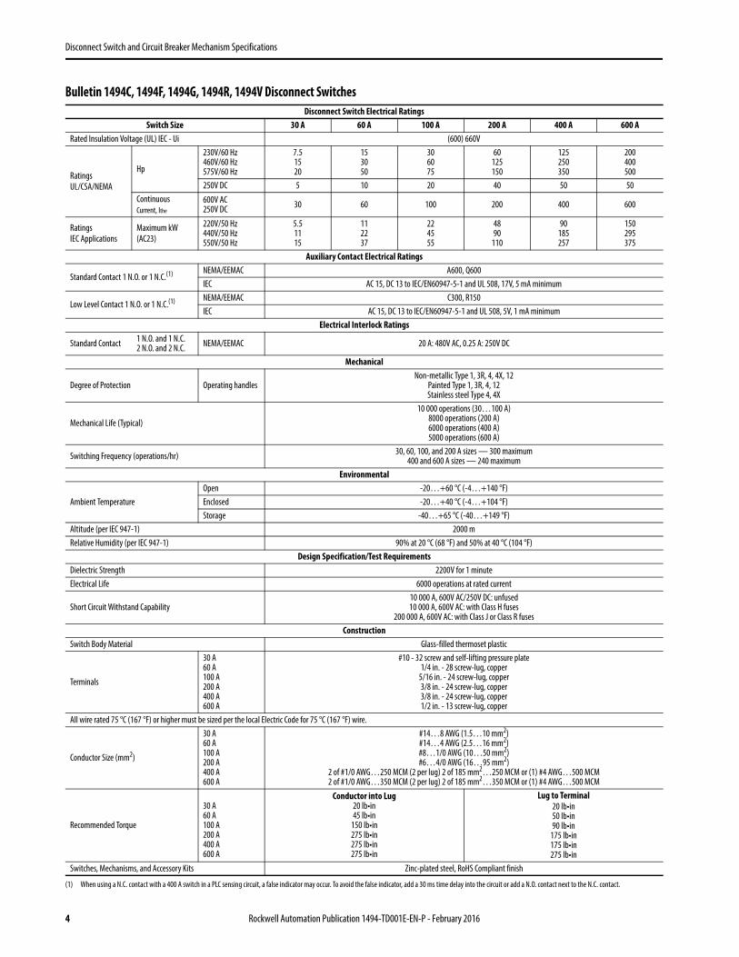
Disconnect Switch and Circuit Breaker Mechanism Specifications
Bulletin 1494C, 1494F, 1494G, 1494R, 1494V Disconnect Switches Disconnect Switch Electrical Ratings
Switch Size 30 A 60 A 100 A 200 A 400 A 600 ARated Insulation Voltage (UL) IEC - Ui (600) 660V
RatingsUL/CSA/NEMA
Hp
230V/60 Hz460V/60 Hz575V/60 Hz
7.51520
153050
306075
60125150
125250350
200400500
250V DC 5 10 20 40 50 50ContinuousCurrent, Ithe
600V AC250V DC 30 60 100 200 400 600
RatingsIEC Applications
Maximum kW(AC23)
220V/50 Hz440V/50 Hz550V/50 Hz
5.51115
112237
224555
4890
110
90185257
150295375
Auxiliary Contact Electrical Ratings
Standard Contact 1 N.O. or 1 N.C.(1)
(1) When using a N.C. contact with a 400 A switch in a PLC sensing circuit, a false indicator may occur. To avoid the false indicator, add a 30 ms time delay into the circuit or add a N.O. contact next to the N.C. contact.
NEMA/EEMAC A600, Q600IEC AC 15, DC 13 to IEC/EN60947-5-1 and UL 508, 17V, 5 mA minimum
Low Level Contact 1 N.O. or 1 N.C.(1) NEMA/EEMAC C300, R150IEC AC 15, DC 13 to IEC/EN60947-5-1 and UL 508, 5V, 1 mA minimum
Electrical Interlock Ratings
Standard Contact 1 N.O. and 1 N.C.2 N.O. and 2 N.C. NEMA/EEMAC 20 A: 480V AC, 0.25 A: 250V DC
Mechanical
Degree of Protection Operating handlesNon-metallic Type 1, 3R, 4, 4X, 12
Painted Type 1, 3R, 4, 12Stainless steel Type 4, 4X
Mechanical Life (Typical)
10 000 operations (30…100 A)8000 operations (200 A)6000 operations (400 A)5000 operations (600 A)
Switching Frequency (operations/hr) 30, 60, 100, and 200 A sizes — 300 maximum400 and 600 A sizes — 240 maximum
Environmental
Ambient TemperatureOpen -20…+60 °C (-4…+140 °F)Enclosed -20…+40 °C (-4…+104 °F)Storage -40…+65 °C (-40…+149 °F)
Altitude (per IEC 947-1) 2000 mRelative Humidity (per IEC 947-1) 90% at 20 °C (68 °F) and 50% at 40 °C (104 °F)
Design Specification/Test RequirementsDielectric Strength 2200V for 1 minuteElectrical Life 6000 operations at rated current
Short Circuit Withstand Capability10 000 A, 600V AC/250V DC: unfused10 000 A, 600V AC: with Class H fuses
200 000 A, 600V AC: with Class J or Class R fusesConstruction
Switch Body Material Glass-filled thermoset plastic
Terminals
30 A60 A100 A200 A400 A600 A
#10 - 32 screw and self-lifting pressure plate1/4 in. - 28 screw-lug, copper
5/16 in. - 24 screw-lug, copper3/8 in. - 24 screw-lug, copper3/8 in. - 24 screw-lug, copper1/2 in. - 13 screw-lug, copper
All wire rated 75 °C (167 °F) or higher must be sized per the local Electric Code for 75 °C (167 °F) wire.
Conductor Size (mm2)
30 A60 A100 A200 A400 A600 A
#14…8 AWG (1.5…10 mm2)#14…4 AWG (2.5…16 mm2)#8…1/0 AWG (10…50 mm2)#6…4/0 AWG (16…95 mm2)
2 of #1/0 AWG…250 MCM (2 per lug) 2 of 185 mm2…250 MCM or (1) #4 AWG…500 MCM2 of #1/0 AWG…350 MCM (2 per lug) 2 of 185 mm2…350 MCM or (1) #4 AWG…500 MCM
Recommended Torque
30 A60 A100 A200 A400 A600 A
Conductor into Lug20 lb•in45 lb•in
150 lb•in275 lb•in275 lb•in275 lb•in
Lug to Terminal20 lb•in50 lb•in90 lb•in
175 lb•in175 lb•in275 lb•in
Switches, Mechanisms, and Accessory Kits Zinc-plated steel, RoHS Compliant finish
4 Rockwell Automation Publication 1494-TD001E-EN-P - February 2016

Disconnect Switch and Circuit Breaker Mechanism Specifications
Bulletin 1494H, 1494HL Disconnect Switches
Disconnect Switch Electrical Ratings
Switch Size 30 A 60 A 100 A 200 A
Rated Insulation Voltage (UL) IEC - Ui (600) 660V
RatingsUL/CSA/NEMA
Hp
230V/60 Hz460V/60 Hz575V/60 Hz
102030
205060
4075
100
60125150
250V DC 5 10 20 40
ContinuousCurrent, Ithe
600V AC250V DC 30 60 100 200
Auxiliary Contact Electrical Ratings
Continuous Current 10 A 15 A
Pole Configuration DPDT DPDT
Mechanical
Degree of Protection Operating handles Painted Type 1, 3R, 12
Mechanical Life (Typical) 10 000 operations
Switching Frequency (operations/hr) 300 maximum
Environmental
Ambient TemperatureOperating -35…+40 °C (-31…+104 °F)
Storage -40…+65 °C (-40…+149 °F)
Altitude (per IEC 947-5) 2000 m
Relative Humidity (per IEC 947-3) 90% at 20 °C (68 °F) and 50% at 40 °C (104 °F)
Design Specification/Test Requirements
Dielectric Strength 2200V for 1 minute
Electrical Life 6000 operations at rated current
Short Circuit Withstand Capability
10 000 A: unfused10 000 A: with Class H fuses
200 000 A: with Class J or Class R fuses (30…100 A)100 000 A: with Class J or Class R fuses (200 A)
Construction
Switch Body Material Phenolic
Contact Material Copper, tin-plated
Terminals
30 A60 A100 A200 A
#10 - 32 screw and self-lifting pressure plate1/4 in. - 28 screw-lug, copper
5/16 in. - 24 screw-lug, copper3/8 in. - 24 screw-lug, copper
All wire rated 75 °C (167 °F) or higher must be sized per the local Electric Code for 75 °C (167 °F) wire.
Conductor Size (mm2)
30 A60 A100 A200 A
#14…8 AWG #12…2 AWG
#10…1/0 AWG#2…250 MCM AWG
Recommended Torque30 A60 A100 A200 A
Conductor into Lug36…40 lb•in35…45 lb•in35…50 lb•in
275 lb•in
Mechanisms Zinc-plated steel, bronze chromate finish
Rockwell Automation Publication 1494-TD001E-EN-P - February 2016 5
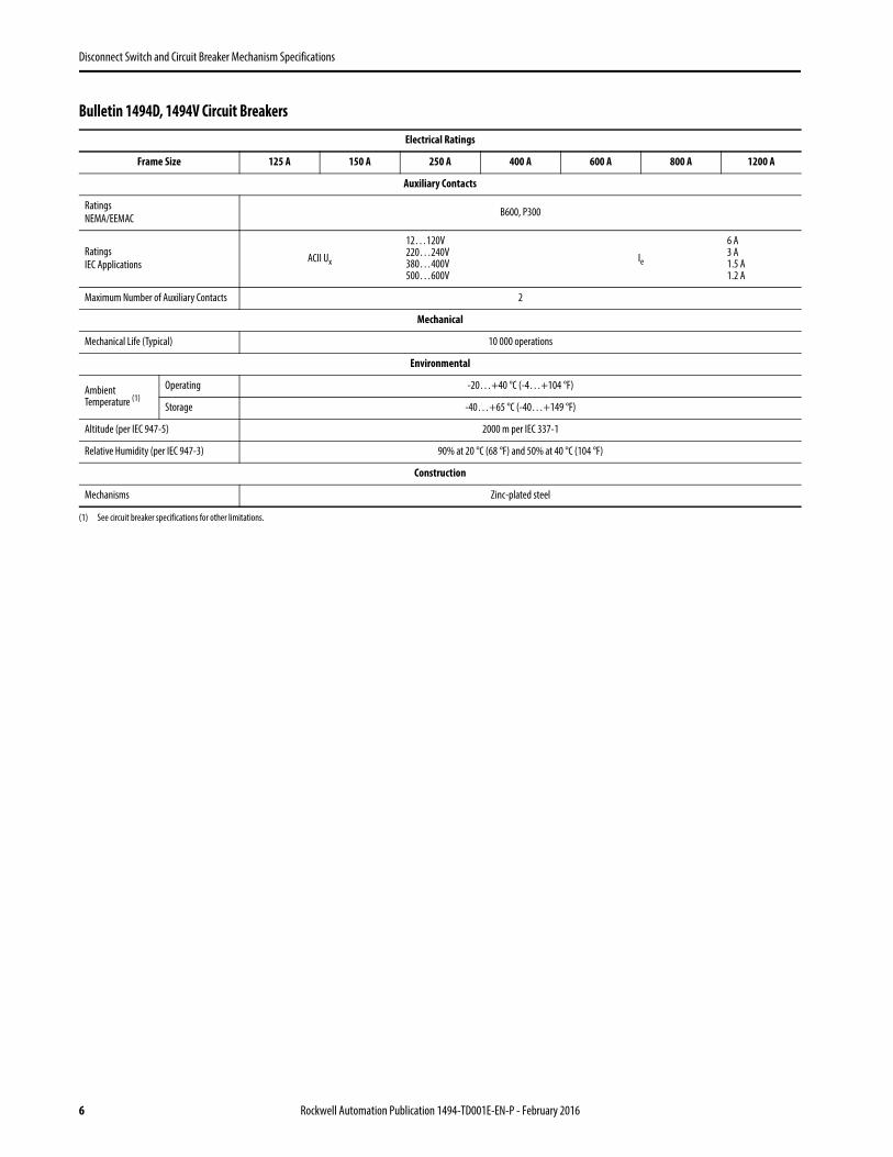
Disconnect Switch and Circuit Breaker Mechanism Specifications
Bulletin 1494D, 1494V Circuit Breakers
Electrical Ratings
Frame Size 125 A 150 A 250 A 400 A 600 A 800 A 1200 A
Auxiliary Contacts
RatingsNEMA/EEMAC B600, P300
RatingsIEC Applications ACII Ux
12…120V220…240V380…400V500…600V
Ie
6 A3 A1.5 A1.2 A
Maximum Number of Auxiliary Contacts 2
Mechanical
Mechanical Life (Typical) 10 000 operations
Environmental
Ambient Temperature (1)
(1) See circuit breaker specifications for other limitations.
Operating -20…+40 °C (-4…+104 °F)
Storage -40…+65 °C (-40…+149 °F)
Altitude (per IEC 947-5) 2000 m per IEC 337-1
Relative Humidity (per IEC 947-3) 90% at 20 °C (68 °F) and 50% at 40 °C (104 °F)
Construction
Mechanisms Zinc-plated steel
6 Rockwell Automation Publication 1494-TD001E-EN-P - February 2016

Disconnect Switch and Circuit Breaker Mechanism Specifications
Bulletin 1494U Disconnect Switch and Fuse Block, 30…60 A
Approximate dimensions are shown in inches. Dimensions are not intended to be used for manufacturing purposes.
3.56 3.63
.51.50
1.811.816.81
4.88MTG.
HOLES
4.91
1.81MTG. HOLES
.2032 MTG. HOLES(FOR 10-32SCREWS)
Ø
3.311.00 DURINGHANDLE ROTATION
1.06
6.02
8.58
.203MTG. HOLES
.29MTG HOLES
.49
LINE AND LOADTERM. THREAD#12-24 UNC
1.81
1.81 1.81
.91
2.332.05
5.20
3.00
1.75
.37
.2032 MTG. HOLES(FOR 10-32SCREWS)
FIELD INSTALLED PHASE BARRIERS(CAN BE ORDERED SEPERATELY)
Ø
Rockwell Automation Publication 1494-TD001E-EN-P - February 2016 7

Disconnect Switch and Circuit Breaker Mechanism Specifications
Bulletin 1494U Disconnect Switch and Fuse Block, 100 A
Approximate dimensions are shown in inches. Dimensions are not intended to be used for manufacturing purposes. 6.81
1.81 1.81
3.311.81MTG. HOLES
1.00 DURINGHANDLE ROTATION
3.56
1.30
.50 .51
3.63
4.88MTG
HOLES
4.91
.81
6.34
8.90
.203MTG HOLES
.29MTG. HOLES
n .2032 MTG HOLES(FOR 10-32SCREWS)
LINE AND LOADTERM. THREAD#12-24 UNC
Ø
5.20
.37
2.05
2.72
1.81 1.81
1.81.91
1.75
3.00
FIELD INSTALLED PHASE BARRIERS(CAN BE ORDERED SEPERATELY)
.2032 MTG HOLES(FOR 10-32SCREWS)
Ø
8 Rockwell Automation Publication 1494-TD001E-EN-P - February 2016

Disconnect Switch and Circuit Breaker Mechanism Specifications
Bulletin 1494U Handle with Support Bracket
Approximate dimensions are shown in inches. Dimensions are not intended for to be used manufacturing purposes.
8.00
2.871.04
Rockwell Automation Publication 1494-TD001E-EN-P - February 2016 9

Disconnect Switch and Circuit Breaker Mechanism Specifications
Bulletin 1494V
Approximate dimensions are shown in inches (millimeters). Dimensions are not intended to be used for manufacturing purposes.
Disconnect Switches (Approximate dimensions are for reference only.)
NEMA Size [A] AB (1)
(1) This approximate dimension varies by fuse class and size.
CD E F Switch Mounting
Hole DiameterMaximum Minimum Maximum
30 6-19/64(160)
7-31/32(202)
6-3/4(171)
21-5/8(549)
2-3/4(69.9)
7-9/16(192)
3-7/8(98.5) 7/32 in.
60 6-19/64(160)
8-15/32(215)
6-3/4(171)
21-5/8(549)
2-9/16(65.1)
7-9/16(192)
3-7/8(98.5) 7/32 in.
100 6-19/64(160)
9-1/8(231.8)
6-3/4(171)
21-5/8(549)
3-37/64(90.9)
7-9/16(192)
3-7/8(98.5) 7/32 in.
200 8-5/64(205.2)
15-9/64(384.5)
9-1/2(241.3)
21-5/8(549)
6-35/64(166.3)
8-25/32(223)
4-21/32(118) 19/64 in.
400 11(279.4)
18-7/32(462.7)
10-1/2(266.7)
21-5/8(549)
8(203.2)
10(254)
5-1/2(139.7) 11/32 in.
600 15-23/32(399.2)
17-19/32(446.8) (2)
(2) Approximate dimension with Class J fuses.
10-1/2(266.7)
21-5/8(549)
12(304.8)
11-27/32(300.8)
8-51/64(223.3) 11/32 in.
Vertical Center Line of Operation Handle DrillingDoor
Provides forWire Bending
Space
DisconnectingMeans
OperatingHandle
MountingSurface
Disconnect MeansMounting Surface
EnclosureFlange
Trailer Fuse Block
Common IndustrialFlange Cut-Out
Vertical CenterLine of Operating
Handle
Center LineOperating
Mechanism
Square Cornersor 1/4 (6.35) R.21/64 (8.3) Dia
2 Holes
Flange Cut-Out
Bulletin 1494V — 30…200 A Bulletin 1494V — 400…600 A
10 Rockwell Automation Publication 1494-TD001E-EN-P - February 2016
Disconnect Switch and Circuit Breaker Mechanism Specifications
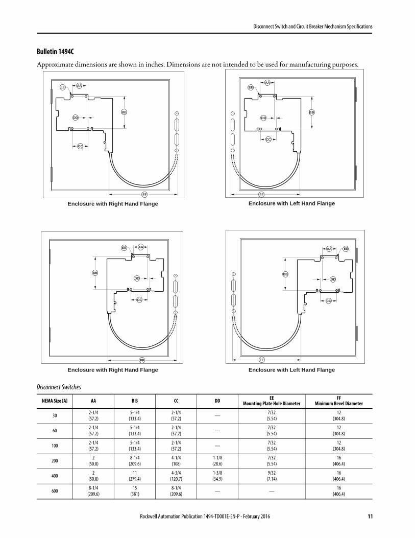
Bulletin 1494C
Approximate dimensions are shown in inches. Dimensions are not intended to be used for manufacturing purposes.
Disconnect Switches
NEMA Size [A] AA B B CC DD EEMounting Plate Hole Diameter
FFMinimum Bevel Diameter
30 2-1/4(57.2)
5-1/4(133.4)
2-1/4(57.2) — 7/32
(5.54)12
(304.8)
60 2-1/4(57.2)
5-1/4(133.4)
2-1/4(57.2) — 7/32
(5.54)12
(304.8)
100 2-1/4(57.2)
5-1/4(133.4)
2-1/4(57.2) — 7/32
(5.54)12
(304.8)
200 2(50.8)
8-1/4(209.6)
4-1/4(108)
1-1/8(28.6)
7/32(5.54)
16(406.4)
400 2(50.8)
11(279.4)
4-3/4(120.7)
1-3/8(34.9)
9/32(7.14)
16(406.4)
600 8-1/4(209.6)
15(381)
8-1/4(209.6) — — 16
(406.4)
Enclosure with Right Hand Flange Enclosure with Left Hand Flange
Enclosure with Right Hand Flange Enclosure with Left Hand Flange
BB
AA
DD
FF
EE
FF
FF
FF
BB
AA
DD
CC
EE
BB
AA
DD
CC
EE
BB
AA
DD
CC
EE
CC
Rockwell Automation Publication 1494-TD001E-EN-P - February 2016 11
Disconnect Switch and Circuit Breaker Mechanism Specifications
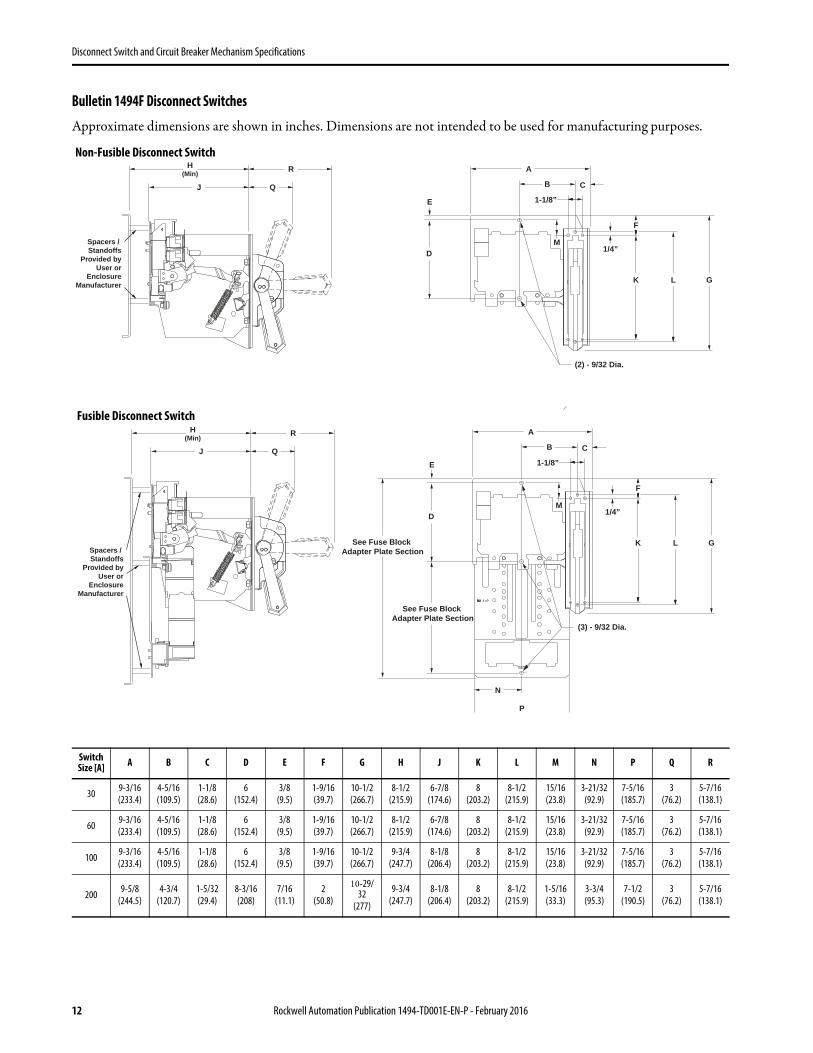
Bulletin 1494F Disconnect Switches
Approximate dimensions are shown in inches. Dimensions are not intended to be used for manufacturing purposes.
Switch Size [A] A B C D E F G H J K L M N P Q R
30 9-3/16(233.4)
4-5/16(109.5)
1-1/8(28.6)
6(152.4)
3/8(9.5)
1-9/16(39.7)
10-1/2(266.7)
8-1/2(215.9)
6-7/8(174.6)
8(203.2)
8-1/2(215.9)
15/16(23.8)
3-21/32(92.9)
7-5/16(185.7)
3(76.2)
5-7/16(138.1)
60 9-3/16(233.4)
4-5/16(109.5)
1-1/8(28.6)
6(152.4)
3/8(9.5)
1-9/16(39.7)
10-1/2(266.7)
8-1/2(215.9)
6-7/8(174.6)
8(203.2)
8-1/2(215.9)
15/16(23.8)
3-21/32(92.9)
7-5/16(185.7)
3(76.2)
5-7/16(138.1)
100 9-3/16(233.4)
4-5/16(109.5)
1-1/8(28.6)
6(152.4)
3/8(9.5)
1-9/16(39.7)
10-1/2(266.7)
9-3/4(247.7)
8-1/8(206.4)
8(203.2)
8-1/2(215.9)
15/16(23.8)
3-21/32(92.9)
7-5/16(185.7)
3(76.2)
5-7/16(138.1)
200 9-5/8(244.5)
4-3/4(120.7)
1-5/32(29.4)
8-3/16(208)
7/16(11.1)
2(50.8)
10-29/32
(277)
9-3/4(247.7)
8-1/8(206.4)
8(203.2)
8-1/2(215.9)
1-5/16(33.3)
3-3/4(95.3)
7-1/2(190.5)
3(76.2)
5-7/16(138.1)
A
D
E
1/4”
F
M
K L G
C
1-1/8”
B
H(Min)
J Q
R
Spacers / Standoffs
Provided byUser or
EnclosureManufacturer
(2) - 9/32 Dia.
A
P
N
D
E
1/4”
F
M
K L G
H(Min)
J C
1-1/8”
B
See Fuse Block Adapter Plate Section
See Fuse Block Adapter Plate Section
Q
R
Spacers / Standoffs
Provided byUser or
EnclosureManufacturer
(3) - 9/32 Dia.
Fusible Disconnect Switch
Non-Fusible Disconnect Switch
12 Rockwell Automation Publication 1494-TD001E-EN-P - February 2016

Disconnect Switch and Circuit Breaker Mechanism Specifications
Bulletin 1494F Disconnect Switches Vault Hardware Latching (Enclosures that are not pre-drilled)
Approximate dimensions are shown in inches. Dimensions are not intended to be used for manufacturing purposes.
Vault Hardware
KitsSwitch Size
[A] A B C (Min.) D E (Min.) F G (Min.) H (Min.) J (Min.) K L M N
Small and Intermediate Enclosures
1494F-L11494F-L21494F-L3
30
3-7/8(98.4)
3/8(9.5)
3-1/16(77.8)
2-1/8(54)
4-1/2(114.3)
3-13/16(96.8)
13(330.2)
8-1/8(206.4)
5(127)
1/2(12.7)
1/4(6.4)
11/16(17.5)
1/2(12.7)
60 14(355.6)
100 18-7/8(479.4)
20023-
25/32(604)
Large Enclosures
1494F-L4
30
4(101.6)
1/2(12.7)
3-3/4(95.3)
2-1/8(54)
5(127)
3-13/16(96.8)
13-1/8(333.4)
9-13/16(249.2)
6(152.4)
5/8(15.9)
5/16(7.9)
1-1/4(31.8)
3/4(19.1)
60 13-5/8(346.1)
100 18-1/2(469.9)
20023-
13/32(594.5)
4 - 3/4”3 - 1/4”
1 - 3/8” 1 - 3/8”
1 - 1/8”
9/16”
3/8”
3/8”
NN
5/16”
1/2”
5/16”
K
L
3/4”
3/4”
B
GuideBracket
Guide Bracket
Door Catch Bracket
Guide Bracket
B
C + 1/16” *
2 - 3/8”
C(Min)
E(Min)
F
1/4”
1/4”
G(Min)
(1494F-L2, 1494F-L4)
H *(Min)
(1494F-L1)3 - 1/4” (1494-L2)
H minus 3/4”
(1494-L4)H minus 1 - 1/8”
(1494F-L1, 1494F-L2)G minus 3/4”
(1494F-L4)G minus 1 - 1/8”
(1494F-L1, 1494F-L2)E + 3 - 1/2”
(1494F-L4)E + 3 - 3/8”
* Non applicable for 1494F-L1
J *(Min)
M
M
13/16”
2 - Holes9/32” Dia.
2 - Holes13/32” Dia.
2 - Holes#10-32
6 - Holes.193” Dia.+.000
-.003
GuideBracket
3/4” Dia.
A
D
(Min)
Option 2Option 1
Rockwell Automation Publication 1494-TD001E-EN-P - February 2016 13

Disconnect Switch and Circuit Breaker Mechanism Specifications
6
6
Bulletin 1494R Disconnect Switches
Approximate dimensions are shown in inches. Dimensions are not intended to be used for manufacturing purposes.
NEMA Size [A]
A B C D E F G H
J
K L M N P Q RStandard Shaft Long Shaft
Min. Max. Min. Max.
30 3-31/32(100.8)
4-13/16(122.2)
3-9/16(90.5)
1-1/8(28.6)
3-1/8(79.4)
3-1/8(79.4)
27/64(10.7)
1(25.4)
4-3/8(111.1)
10-7/8(276.2)
4-3/8(111.1)
19-3/8(492.1)
(1)
(1) The adjusted coupling position is determined by measuring the cabinet depth and subtracting 9/16 in.
(3)
(3) The adjusted coupling position is determined by measuring the cabinet depth and subtracting 15/16 in.
1(25.4)
3/16(4.8)
5(127.0)
2-13/16(71.4)
2-13/1(71.4)
60 4-21/32(118.3)
5-1/4(133.4)
3-9/16(90.5)
1-1/16(27.0)
3-13/16(96.8)
3-1/8(79.4)
27/64(10.7)
1(25.4)
4-1/2(114.3)
10-7/8(276.2)
4-1/2(114.3)
19-3/8(492.1)
1(25.4)
3/16(4.8)
5(127.0)
2-13/16(71.4)
2-13/1(71.4)
100 6-7/16(163.5)
7-3/16(187.3)
5-7/16(138.1)
15/16(23.8)
5(127.0)
5(127.0)
23/32(18.3)
1-1/2(38.1)
6-1/4(158.8)
12-7/8(327.0)
6-1/4(158.8)
25-7/8(657.2)
(2)
(2) The shaft length is determined by measuring the cabinet depth (dimension J) and subtracting 1-3/8 in.
(4)
(4) The shaft length is determined by measuring the cabinet depth (dimension J) and subtracting 1-7/8 in.
1-3/8(34.9)
1/4(6.4)
7-11/16(195.3)
4-3/16(106.4)
3(76.2)
200 7-1/4(184.2)
9-1/2(241.3)
6-1/2(165.1)
1-7/16(36.5)
5-3/4(146.1)
5-3/4(146.1)
3/4(19.1)
1-23/32(43.7)
7-7/16(188.9)
12-7/8(327.0)
7-7/16(188.9)
25-7/8(657.2)
1-3/8(34.9)
1/4(6.4)
7-11/16(195.3)
4-3/16(106.4)
3(76.2)
From Inside of Cover toBottom of DisconnectSwitch Mounting BracketOPEN
OFFON
of Handle
cL
Switch
4 Mtg. Holes
of Handle
Aux.Sw.
Aux.Sw.
Aux.Sw.
Aux.Sw.
Hitch Pin Hole
3 Holes15/64 (6) Dia
1-1/2 (38.1) Dia.
Cover Drilling
1/2 (12.7) Dia.
Bulletin 1494R — 100…200 A
Bulletin 1494R — 100…200 A
14 Rockwell Automation Publication 1494-TD001E-EN-P - February 2016

Disconnect Switch and Circuit Breaker Mechanism Specifications
Bulletin 1494V
Approximate dimensions are shown in inches. Dimensions are not intended to be used for manufacturing purposes.
Bulletin 140G Circuit Breakers (Approximate dimensions are for reference only.)
Frame AC
D E FMinimum Maximum
125 A140G-G, -H140MG-G, -H
5-7/64(130.0)
6-3/4(171.5)
23(584.2)
2(50.8)
5-3/4(147.0)
7-13/64(182.8)
225 A140G-I, 140MG-I
5-13/32 (150.0)
7-7/8(200.0)
22-9/16(573.1)
6(152.4)
5-3/4(147.0)
7-13/64(182.8)
250 A140G-J, 140MG-J
6-19/64 (160.0)
7-7/8(200.0)
22-9/16(573.1)
6(152.4)
5-3/4(147.0)
7-13/64(182.8)
400 A140G-K, 140MG-K
8.1(204.9)
7-7/8(200.0)
22-9/16(573.1)
12(304.8)
7-1/4(183.0)
8-23/64(225.1)
800 A140G-M, 140MG-M
10-3/64(268.0)
11-3/16(284.2)
22-9/16(573.1)
12(304.8)
10-3/64(255.2)
9-3/64(229.6)
1200 A140G-N, 140MG-N
10-3/64(268.0)
11-3/16(284.2)
22-9/16(573.1)
12(304.8)
10-3/64(255.2)
9-3/64(229.6)
Vertical Center Line of Operation Handle DrillingDoor
Provides forWire Bending
Space
DisconnectingMeans
OperatingHandle
MountingSurface
Disconnect MeansMounting Surface
EnclosureFlange
Trailer Fuse Block
Common IndustrialFlange Cut-Out
CircuitBreakerAuxiliary
(When Used)
Vertical CenterLine of Operating
Handle
Center LineOperating
Mechanism
Square Cornersor 1/4 (6.35) R.21/64 (8.3) Dia
2 Holes
Flange Cut-Out
Bulletin 1494V — 125…400 A Bulletin 1494R — 800…1200 A
Rockwell Automation Publication 1494-TD001E-EN-P - February 2016 15

Disconnect Switch and Circuit Breaker Mechanism Specifications
Bulletin 1494D Circuit Breakers
Approximate dimensions are shown in inches. Dimensions are not intended to be used for manufacturing purposes.
Approximate dimensions are for reference only.
Cutler-Hammer Frame A
CD E F
Minimum Maximum
150 A — EHD, FD,FDB, FDC, HFD,HMCP
7-13/16 (198.4) 6-3/8 (161.9) — 6 (152.4) 5-5/8 (142.9) 6-7/16 (163.5)
250 A — JD, JDB,JDC, HJD, HMCP 11-1/2 (292.1) 8-3/8 (212.7) — 8 (203.2) 5-13/16 (147.6) 9-7/16 (239.7)
400 A — KD, KDB,KDC, HKD, HMCP 11-1/2 (292.1) 8-3/8 (212.7) — 12 (304.8) 6-7/8 (174.6) 9-7/16 (239.7)
600 A — LD, HLD,LDC, LA, HLA, LC,HLC
11-3/8 (288.9) 9-1/2 (241.3) — 8 (203.2) 12 (304.8) 10-17/32 (267.5)
800 A — MA, MDL,HMDL, HMA, MC,ND, HND, NDC
16 (406.4) 9-1/2 (241.3) — 10 (254) 12-5/16 (312.7) 15-3/32 (183.4)
1200 A — NB TRIPAK 22 (558.8 9-1/2 (241.3) — 10 (254) 12-5/16 (312.7) 21-3/32 (535.8)
1200 A — HNC, ND,HND, NDC, NB,HNB, NC, HNC
16 (406.4) 9-1/2 (241.3) — 12 (304.8) 12-5/16 (312.7) 25-3/32 (183.4)
Vertical Center Line of Operation Handle DrillingDoor
Provides forWire Bending
DisconnectingMeans
OperatingHandle
MountingSurface
Disconnect MeansMounting Surface
EnclosureFlange
Trailer Fuse Block
CircuitBreakerAuxiliary
(When Used)
Common IndustrialFlange Cut-Out
J
GMin.
Disconnect Switch
Door Catch
Flange Cut-Out
16 Rockwell Automation Publication 1494-TD001E-EN-P - February 2016
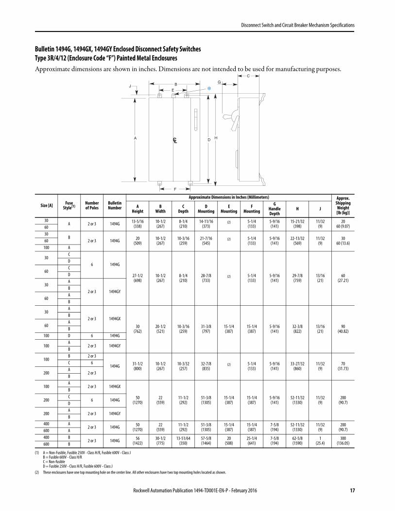
Disconnect Switch and Circuit Breaker Mechanism Specifications
Bulletin 1494G, 1494GX, 1494GY Enclosed Disconnect Safety SwitchesType 3R/4/12 (Enclosure Code “F”) Painted Metal EnclosuresApproximate dimensions are shown in inches. Dimensions are not intended to be used for manufacturing purposes.
Size [A] Fuse Style(1)
(1) A = Non-Fusible, Fusible 250V - Class H/R, Fusible 600V - Class JB = Fusible 600V - Class H/RC = Non-fusibleD = Fusible 250V - Class H/R, Fusible 600V - Class J
Number of Poles
Bulletin Number
Approximate Dimensions in Inches (Millimeters) Approx. Shipping Weight[lb (kg)]
A Height
B Width
CDepth
DMounting
EMounting
FMounting
GHandle Depth
H J
30A 2 or 3 1494G 13-5/16
(338)10-1/2(267)
8-1/4(210)
14-11/16(373)
(2)
(2) These enclosures have one top mounting hole on the center line. All other enclosures have two top mounting holes located as shown.
5-1/4(133)
5-9/16(141)
15-21/32(398)
11/32(9)
2060 (9.07)60
30B
2 or 3 1494G 20(509)
10-1/2(267)
10-3/16(259)
21-7/16(545)
(2) 5-1/4(133)
5-9/16(141)
22-13/32(569)
11/32(9)
3060 (13.6)60
100 A
30C
6 1494G
27-1/2(698)
10-1/2(267)
8-1/4(210)
28-7/8(733)
(2) 5-1/4(133)
5-9/16(141)
29-7/8(759)
13/16(21)
60(27.21)
D
60CD
30A
2 or 3 1494GYB
60AB
30A
2 or 3 1494GX
30(762)
20-1/2(521)
10-3/16(259)
31-3/8(797)
15-1/4(387)
15-1/4(387)
5-9/16(141)
32-3/8(822)
13/16(21)
90(40.82)
B
60AB
100 D 6 1494G
100A
2 or 3 1494GYB
100B 2 or 3
1494G 31-1/2(800)
10-1/2(267)
10-3/32(257)
32-7/8(835)
(2) 5-1/4(133)
5-9/16(141)
33-27/32(860)
11/32(9)
70(31.73)
C 6
200A
2 or 3B
100A
2 or 3 1494GX
50(1270)
22(559)
11-1/2(292)
51-3/8(1305)
15-1/4(387)
15-1/4(387)
5-9/16(141)
52-11/32(1330)
11/32(9)
200(90.7)
B
200C
6 1494GD
200A
2 or 3 1494GYB
400 A2 or 3 1494G 50
(1270)22
(559)11-1/2(292)
51-3/8(1305)
15-1/4(387)
15-1/4(387)
7-5/8(194)
52-11/32(1330)
11/32(9)
200(90.7)600 A
400 B2 or 3 1494G 56
(1422)30-1/2(775)
13-51/64(350)
57-5/8(1464)
20(508)
25-1/4(641)
7-5/8(194)
62-5/8(1590)
1(25.4)
300(136.05)600 B
Rockwell Automation Publication 1494-TD001E-EN-P - February 2016 17

Disconnect Switch and Circuit Breaker Mechanism Specifications
Bulletin 1494G, 1494GX, 1494GY Enclosed Disconnect Safety SwitchesType 4/4X (Enclosure Code “C”) Stainless Steel Enclosures
Approximate dimensions are shown in inches. Dimensions are not intended to be used for manufacturing purposes.
Size [A] Fuse Style(1)
(1) A = Non-Fusible, Fusible 250V - Class H/R, Fusible 600V - Class JB = Fusible 600V - Class H/RC = Non-fusibleD = Fusible 250V - Class H/R, Fusible 600V - Class J
Number of Poles
Bulletin Number
Approximate Dimensions in Inches (Millimeters) Approx. Shipping Weight[lb (kg)]
A Height
B Width
CDepth
DMounting
EMounting
FMounting
GHandle Depth
H J
30A 2 or 3 1494G 13-5/16
(338)10-1/2(267)
8-1/4(210)
14-11/16(373)
(2)
(2) These enclosures have one top mounting hole on the center line. All other enclosures have two top mounting holes located as shown.
7(178)
5-9/16(141)
15-21/32(398)
13/16(21)
2060 (9.07)60
30
B 2 or 3
1494G
27-1/2(698)
10-1/2(267)
8-1/4(210)
28-7/8(733)
(2) 7(178)
5-9/16(141)
29-3/4(756)
13/16(21)
60(27.21)
C6
D
60
B 2 or 3
C6
D
30A
2 or 3 1494GYB
60A
B
30A
2 or 3 1494GX
30(762)
20-1/2(521)
9-7/8(254)
31-3/8(797)
17(432)
17(432)
5-9/16(141)
32-1/4(819)
13/16(21)
90(40.82)
B
60A
B
100
A2 or 3
1494GB
C6
D
100A
2 or 3 1494GX
50(1270)
22(559)
11-3/16(284)
51-3/8(1305)
18-1/2(470)
18-1/2(470)
5-9/16(141)
52-1/4(1327)
13/16(21)
200(90.7)
B
200
A2 or 3
1494GB
C6
D
400A
2 or 3 1494G 56(1422)
30-1/2(775)
13-51/64(350)
57-5/8(1464)
20(508)
25-1/4(641)
7-5/8(194)
58-5/8(1489)
1(25.4)
300(136.05)
B
600A
B
18 Rockwell Automation Publication 1494-TD001E-EN-P - February 2016

Disconnect Switch and Circuit Breaker Mechanism Specifications
Bulletin 1494G Safety Switch — Hazardous Locations
Approximate dimensions are shown in inches. Dimensions are not intended to be used for manufacturing purposes.
Breather1/2 in. NPT
2 in.NPT
3/4 in.NPT
17.3715.51
14.5
18.5
Ø5.53.0
Both Ends3.0
Both Ends
9.878.75
3.76BothEnds
3/4 in.NPT
2 in.NPT
1.86
Vent1/2 in. NPT
Scale 0.200
10.81
16.5
12.337.0
0.484 places
16.33
Rockwell Automation Publication 1494-TD001E-EN-P - February 2016 19

Disconnect Switch and Circuit Breaker Mechanism Specifications
Bulletin 1494H Heavy-Duty Safety SwitchesType 1 (Enclosure Code “A”) General-Purpose Painted Metal Enclosures
Approximate dimensions are shown in inches. Dimensions are not intended to be used for manufacturing purposes.
Knockouts — Conduit Size
Switch Size [A] Fuse Style AHeight
BWidth
CDepth
DWidth (with handle) Knockout Figure #
30240V 10-9/32 (261.1) 6-3/8 (162.1) 3-5/16 (84.1) 7-1/8 (181) 1600V 12-19/32 (319.8) 8-3/8 (212.9) 4 (101.6) 9-1/2 (241.3) 2
Non-fusible 10-3/8 (263.7) 8-3/8 (212.9) 4 (101.6) 9-1/4 (235) 3
60240V 17-19/32 (446.8)
9-3/8 (238.3) 5 (127) 10-3/64 (255.3)4
600V 21-11/32 (542) 5Non-fusible 17-19/32 (446.8) 4
100240V 21-11/32 (542)
9-3/8 (238.3) 5 (127) 10-3/64 (255.3)5
600V 22-11/32 (567.4) 4Non-fusible 17-19/32 (446.8) 4
200240V
31-5/8 (803.3) 13-7/16 (341.4) 5-1/4 (133.4) 14-7/16 (366) 6600VNon-fusible
Switch Size [A] Fuse StyleKnockouts
A B C D E
30240V
9/32 (7.1) 1/2 x 3/4(12.7 x 19.1)
3/8 x 1/2 x 3/4 x 1(9.5 x 12.7 x 19.1 x 25.4) — —
600V 1/2 x 3/4 x 1(12.7 x 19.1 x 25.4)
1/2 x 3/4 x 1 x 1-1/4(12.7 x 19.1 x 25.4 x 31.8)
3/4 x 1 x 1-1/4 x 1-1/2(19.1 x 25.4 x 31.8 x 38.1)Non-fusible
60240V
9/32 (7.1) 1/2 x 3/4 x 1 x 1-1/4(12.7 x 19.1 x 25.4 x 31.8)
3/4 x 1 x 1-1/4 x 1-1/2(19.1 x 25.4 x 31.8 x 38.1)
1 x 1-1/4 x 1-1/2 x 2(25.4 x 31.8 x 38.1 x 50.8) —600V
Non-fusible
100240V
9/32 (7.1) 1/2 x 3/4 x 1 x 1-1/4(12.7 x 19.1 x 25.4 x 31.8)
3/4 x 1 x 1-1/4 x 1-1/2(19.1 x 25.4 x 31.8 x 38.1)
1 x 1-1/4 x 1-1/2 x 2(25.4 x 31.8 x 38.1 x 50.8) —600V
Non-fusible
200240V
1 x 1-1/2 x 2 x 2-1/2(25.4 x 38.1 x 50.8 x 63.5) 9/32 (7.1) 1/2 (12.7) — —600V
Non-fusible
B
D
C
A
A A A
BA A AA
A A AB
A AA
A
C
C
C D BA
D C CD
C C D
AC BD
B
C D BA
D C CD
C C DA
AC BD
B
D E CA
D D BD
D C CA
AD CE
D E CA
D D BD
D C DA
AD CE
B C BA
B B BC
B B B BA
AB BC
Figure 1 Figure 2 Figure 3
Figure 4 Figure 5 Figure 6
20 Rockwell Automation Publication 1494-TD001E-EN-P - February 2016

Disconnect Switch and Circuit Breaker Mechanism Specifications
Bulletin 1494H Heavy-Duty Safety SwitchesType 3R (Enclosure Code “N”) Rain-Proof Painted Metal Enclosures
Approximate dimensions are shown in inches. Dimensions are not intended to be used for manufacturing purposes.
Knockouts — Conduit Size
Switch Size [A] Fuse Style AHeight
BWidth
CDepth
DWidth (with handle) Knockout Figure #
30
240V 10-5/8 (269.9) 6-3/8 (162.1) 3-5/16 (84.1) 7-1/8 (181) 7
600V13-13/64 (335.3) 8-3/8 (212.9) 4 (101.6) 9-13/32 (239) 8
Non-fusible
60
240V 17-7/16 (443)
9-3/8 (238.3) 5 (127)
10-3/64 (255.3)
9600V 22-3/16 (563.6) 10-1/2 (267)
Non-fusible 17-7/16 (443) 10-3/64 (255.3)
100
240V 22-3/16 (563.6)
9-3/8 (238.3) 5 (127)
10-1/2 (267)
9600V 22-3/16 (563.6) 10-1/2 (267)
Non-fusible 17-7/16 (443) 10-3/64 (255.3)
200
240V
31-7/16 (798.6) 13-3/8 (339.9) 5-15/32 (138.9) 14-1/8 (361.9) 10600V
Non-fusible
Switch Size [A] Fuse StyleKnockouts
A B C D
30
240V
9/32 (7.1)
1/2 x 3/4(12.7 x 19.1)
3/8 x 1/2 x 3/4 x 1(9.5 x 12.7 x 19.1 x 25.4) —
600V 1/2 x 3/4 x 1(12.7 x 19.1 x 25.4)
1/2 x 3/4 x 1 x 1-1/4(12.7 x 19.1 x 25.4 x 31.8)
3/4 x 1 x 1-1/4 x 1-1/2(19.1 x 25.4 x 31.8 x 38.1)Non-fusible
60
240V
9/32 (7.1) 1/2 x 3/4 x 1 x 1-1/4(12.7 x 19.1 x 25.4 x 31.8)
3/4 x 1 x 1-1/4 x 1-1/2(19.1 x 25.4 x 31.8 x 38.1)
1 x 1-1/4 x 1-1/2 x 2(25.4 x 31.8 x 38.1 x 50.8)600V
Non-fusible
100
240V
9/32 (7.1) 1/2 x 3/4 x 1 x 1-1/4(12.7 x 19.1 x 25.4 x 31.8)
3/4 x 1 x 1-1/4 x 1-1/2(19.1 x 25.4 x 31.8 x 38.1)
1 x 1-1/4 x 1-1/2 x 2(25.4 x 31.8 x 38.1 x 50.8)600V
Non-fusible
200
240V1 x 1-1/2 x 2 x 2-1/2
(25.4 x 38.1 x 50.8 x 63.5) 9/32 (7.1) 1/2 (12.7) —600V
Non-fusible
B
D
C
A
Figure 7 Figure 9 Figure 10Figure 8
A A A A
C
B
A A A
C B C DA
AC D B
C B CA
AC D B
B B B BA
AB C B
Rockwell Automation Publication 1494-TD001E-EN-P - February 2016 21
Disconnect Switch and Circuit Breaker Mechanism Specifications
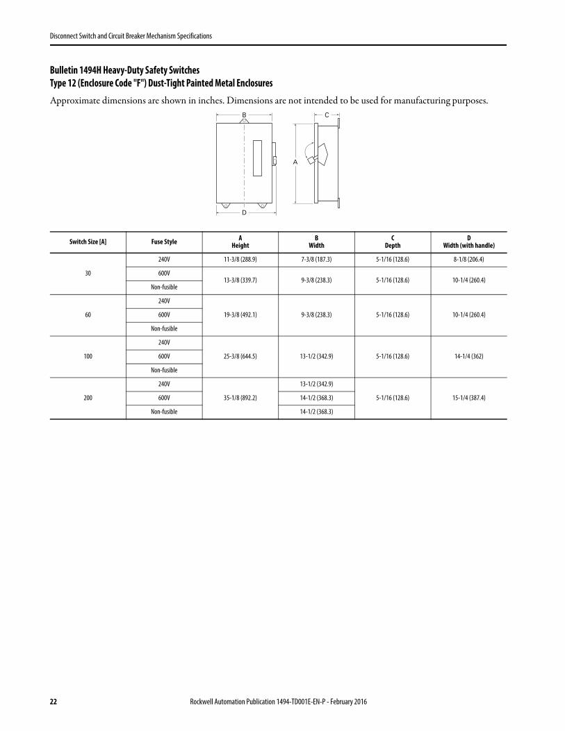
Bulletin 1494H Heavy-Duty Safety SwitchesType 12 (Enclosure Code "F") Dust-Tight Painted Metal Enclosures
Approximate dimensions are shown in inches. Dimensions are not intended to be used for manufacturing purposes.
Switch Size [A] Fuse Style AHeight
BWidth
CDepth
DWidth (with handle)
30
240V 11-3/8 (288.9) 7-3/8 (187.3) 5-1/16 (128.6) 8-1/8 (206.4)
600V13-3/8 (339.7) 9-3/8 (238.3) 5-1/16 (128.6) 10-1/4 (260.4)
Non-fusible
60
240V
19-3/8 (492.1) 9-3/8 (238.3) 5-1/16 (128.6) 10-1/4 (260.4)600V
Non-fusible
100
240V
25-3/8 (644.5) 13-1/2 (342.9) 5-1/16 (128.6) 14-1/4 (362)600V
Non-fusible
200
240V
35-1/8 (892.2)
13-1/2 (342.9)
5-1/16 (128.6) 15-1/4 (387.4)600V 14-1/2 (368.3)
Non-fusible 14-1/2 (368.3)
B
D
C
A
22 Rockwell Automation Publication 1494-TD001E-EN-P - February 2016

Disconnect Switch and Circuit Breaker Mechanism Specifications
Bulletin 1494HL General Duty Safety SwitchesType 1 (Enclosure Code “A”) General-Purpose Painted Metal Enclosures
Approximate dimensions are shown in inches. Dimensions are not intended to be used for manufacturing purposes.
Knockouts — Conduit Size
Switch Size [A] Fuse Style AHeight
BWidth
CDepth
DWidth (with handle) Knockout Figure #
30
240V
10-9/32 (261.1) 6-1/2 (165.1) 3-5/16 (84.1) 6-29/32 (175.3) 1
60 13-27/32 (351.5) 8-1/2 (215.9) 4 (101.6) 8-7/8 (225.6) 2
100 21-11/32 (542) 9-1/2 (241.3) 5 (127) 9-7/8 (251) 3
200 29-1/8 (739.6) 13-7/16 (341.4) 5-5/16 (134.9) 13-15/16 (354.1) 4
Switch Size [A]Knockouts
A B C D E
30 9/32 (7.1) 1/2 x 3/4(12.7 x 19.1)
3/8 x 1/2 x 3/4 x 1(9.5 x 12.7 x 19.1 x 25.4) — —
60 9/32 (7.1) 1/2 x 3/4(12.7 x 19.1)
1/2 x 3/4 x 1(12.7 x 19.1 x 25.4)
1/2 x 3/4 x 1 x 1-1/4(12.7 x 19.1 x 25.4 x 31.8)
3/4 x 1 x 1-1/4 x 1-1/2(19.1 x 25.4 x 31.8 x 38.1)
100 9/32 (7.1) 1/2 x 3/4 x 1 x 1-1/4(12.7 x 19.1 x 25.4 x 31.8)
3/4 x 1 x 1-1/4 x 1-1/2(19.1 x 25.4 x 31.8 x 38.1)
1 x 1-1/4 x 1-1/2 x 2(25.4 x 31.8 x 38.1 x 50.8) —
200 1/2 (12.7) 1 x 1-1/2 x 2 x 2-1/2(25.4 x 38.1 x 50.8 x 63.5) 9/32 (7.1) — —
B
D
C
A
Figure 1 Figure 3 Figure 4Figure 2
B B B
CB B BB
B B BC
B BB
B
A
A
C D BA
D C CD
C C DA
AC BD
B
D E CA
D D BD
D C DA
AD CE
B C BA
B B BC
B B B BA
AB BC
Rockwell Automation Publication 1494-TD001E-EN-P - February 2016 23

Disconnect Switch and Circuit Breaker Mechanism Specifications
Bulletin 1494HL General Duty Safety SwitchesType 3R (Enclosure Code “N”) Rain-Proof Painted Metal Enclosures
Approximate dimensions are shown in inches. Dimensions are not intended to be used for manufacturing purposes.
Knockouts — Conduit Size
Switch Size [A] Fuse Style AHeight
BWidth
CDepth
DWidth (with handle) Knockout Figure #
30
240V
10-1/32 (254.8) 6-3/8 (162.1) 3-5/16 (84.1) 7-1/8 (180.8) 5
60 13-15/16 (353.8) 8-3/8 (212.9) 3-7/8 (225.6) 9-3/32 (230.9) 6
100 21-7/16 (544.3) 9-3/8 (238.3) 5 (127) 9-61/64 (252.7) 7
200 28-15/16 (735.1) 13-3/8 (339.9) 5-5/16 (134.9) 14-1/16 (357.1) 8
Switch Size [A]Knockouts
A B C D
30 9/32 (7.1) 1/2 x 3/4(12.7 x 19.1)
3/8 x 1/2 x 3/4 x 1(9.5 x 12.7 x 19.1 x 25.4) —
60 9/32 (7.1) 1/2 x 3/4 x 1(12.7 x 19.1 x 25.4)
1/2 x 3/4 x 1 x 1-1/4(12.7 x 19.1 x 25.4 x 31.8)
3/4 x 1 x 1-1/4 x 1-1/2(19.1 x 25.4 x 31.8 x 38.1)
100 9/32 (7.1) 1/2 x 3/4 x 1 x 1-1/4(12.7 x 19.1 x 25.4 x 31.8)
3/4 x 1 x 1-1/4 x 1-1/2(19.1 x 25.4 x 31.8 x 38.1)
1 x 1-1/4 x 1-1/2 x 2(25.4 x 31.8 x 38.1 x 50.8)
200 1/2 (12.7) 1 x 1-1/2 x 2 x 2-1/2(25.4 x 38.1 x 50.8 x 63.5)
1 x 1-1/2 x 2 x 2-1/2(25.4 x 38.1 x 50.8 x 63.5) —
B
D
C
A
Figure 5 Figure 7 Figure 8Figure 6
C C C C
A
B
C C C
C B C DA
AC D B
C B CA
AC D B
B B B BA
AB C B
24 Rockwell Automation Publication 1494-TD001E-EN-P - February 2016

Disconnect Switch and Circuit Breaker Mechanism Specifications
Notes:
Rockwell Automation Publication 1494-TD001E-EN-P - February 2016 25
Allen-Bradley, Rockwell Software, Rockwell Automation, and LISTEN. THINK. SOLVE are trademarks of Rockwell Automation, Inc.Trademarks not belonging to Rockwell Automation are property of their respective companies.
Publication 1494-TD001E-EN-P - February 2016
Rockwell Automation SupportUse the following resources to access support information.
Documentation FeedbackYour comments will help us serve your documentation needs better. If you have any suggestions on how to improve this document, complete the How Are We Doing? form at http://literature.rockwellautomation.com/idc/groups/literature/documents/du/ra-du002_-en-e.pdf.
Technical Support Center Knowledgebase Articles, How-to Videos, FAQs, Chat, User Forums, and Product Notification Updates. www.rockwellautomation.com/knowledgebase
Local Technical Support Phone Numbers Locate the phone number for your country. www.rockwellautomation.com/global/support/get-support-now.page
Direct Dial CodesFind the Direct Dial Code for your product. Use the code to route your call directly to a technical support engineer.
www.rockwellautomation.com/global/support/direct-dial.page
Literature Library Installation Instructions, Manuals, Brochures, and Technical Data. www.rockwellautomation.com/literature
Product Compatibility and Download Center (PCDC)
Get help determining how products interact, check features and capabilities, and find associated firmware.
www.rockwellautomation.com/global/support/pcdc.page
Rockwell Otomasyon Ticaret A.Ş., Kar Plaza İş Merkezi E Blok Kat:6 34752 İçerenköy, İstanbul, Tel: +90 (216) 5698400
Rockwell Automation maintains current product environmental information on its website at http://www.rockwellautomation.com/rockwellautomation/about-us/sustainability-ethics/product-environmental-compliance.page.
Supersedes Publication 1494-TD001D-EN-P - April 2015 Copyright © 2016 Rockwell Automation, Inc. All rights reserved. Printed in the U.S.A.