DISC HARROW NUAL - Woods Equipment Company s m a disc harrow nual man1143 (rev. 1/08/2018) dhs48,...
36
OPERATOR'S MANUAL DISC HARROW MAN1143 (Rev. 1/08/2018) DHS48, DHS64, DHS80 DHM80, DHM96
Transcript of DISC HARROW NUAL - Woods Equipment Company s m a disc harrow nual man1143 (rev. 1/08/2018) dhs48,...

OP
ER
AT
OR
'S M
AN
UA
LDISC HARROWM
AN
1143
(Rev
. 1/0
8/2
018
)
DHS48, DHS64, DHS80DHM80, DHM96

2 Introduction Gen’l (Rev. 2/25/2016)
TO THE DEALER:
Assembly and proper installation of this product is the responsibility of the Woods® dealer. Read manual instructionsand safety rules. Make sure all items on the Dealer’s Pre-Delivery and Delivery Check Lists in the Operator’s Manualare completed before releasing equipment to the owner.
The dealer must complete the online Product Registration form at the Woods Dealer Website which certifies thatall Dealer Check List items have been completed. Dealers can register all Woods product atdealer.WoodsEquipment.com under Product Registration.
Failure to register the product does not diminish customer’s warranty rights.
TO THE OWNER:
Read this manual before operating your Woods equipment. The information presented will prepare you to do a better andsafer job. Keep this manual handy for ready reference. Require all operators to read this manual carefully and becomeacquainted with all adjustment and operating procedures before attempting to operate. Replacement manuals can beobtained from your dealer. To locate your nearest dealer, check the Dealer Locator at www.WoodsEquipment.com, or inthe United States and Canada call 1-800-319-6637.
The equipment you have purchased has been carefully engineered and manufactured to provide dependable andsatisfactory use. Like all mechanical products, it will require cleaning and upkeep. Lubricate the unit as specified.Observe all safety information in this manual and safety decals on the equipment.
For service, your authorized Woods dealer has trained mechanics, genuine Woods service parts, and the necessarytools and equipment to handle all your needs.
Use only genuine Woods service parts. Substitute parts will void the warranty and may not meet standards required forsafe and satisfactory operation. Record the model number and serial number of your equipment in the spacesprovided:
Model: _______________________________ Date of Purchase: _____________________
Serial Number: (see Safety Decal section for location) ____________________________________
Provide this information to your dealer to obtain correct repair parts.
Throughout this manual, the term NOTICE is used to indicate that failure to observe can cause damage to equipment.The terms CAUTION, WARNING, and DANGER are used in conjunction with the Safety-Alert Symbol (a triangle withan exclamation mark) to indicate the degree of hazard for items of personal safety.

Introduction 3MAN1143 (7/20/2015)
TABLE OF CONTENTS
INTRODUCTION . . . . . . . . . . . . . . . . . . . . . . . . . . . . . . . . . . . . . . . . . . . . . . 2
SPECIFICATIONS. . . . . . . . . . . . . . . . . . . . . . . . . . . . . . . . . . . . . . . . . . . . . 4
GENERAL INFORMATION . . . . . . . . . . . . . . . . . . . . . . . . . . . . . . . . . . . . . . 4
SAFETY RULES . . . . . . . . . . . . . . . . . . . . . . . . . . . . . . . . . . . . . . . . . . . . . . 5
SAFETY DECALS . . . . . . . . . . . . . . . . . . . . . . . . . . . . . . . . . . . . . . . . . . . . . 7
OPERATION . . . . . . . . . . . . . . . . . . . . . . . . . . . . . . . . . . . . . . . . . . . . . . . . . 9
SERVICE. . . . . . . . . . . . . . . . . . . . . . . . . . . . . . . . . . . . . . . . . . . . . . . . . . . 13
ASSEMBLY INSTRUCTIONS . . . . . . . . . . . . . . . . . . . . . . . . . . . . . . . . . . . 15
DEALER CHECK LISTS . . . . . . . . . . . . . . . . . . . . . . . . . . . . . . . . . . . . . . . 18
PARTS LIST . . . . . . . . . . . . . . . . . . . . . . . . . . . . . . . . . . . . . . . . . . . . . . . . 19
BOLT TORQUE CHART . . . . . . . . . . . . . . . . . . . . . . . . . . . . . . . . . . . . . . . 32
BOLT SIZE CHART & ABBREVIATIONS . . . . . . . . . . . . . . . . . . . . . . . . . . 33
REPLACEMENT PARTS WARRANTY . . . . . . . . . . . . . . . . . . . . . . . . . . . . 34
PRODUCT WARRANTY . . . . . . . . . . . . . . . . . . . . . . . INSIDE BACK COVER

4 Introduction MAN1143 (7/20/2015)
SPECIFICATIONS
GENERAL INFORMATION
The purpose of this manual is to assist you in operatingand maintaining your Disc Harrow. Read it carefully. Itfurnishes information and instructions that will help youachieve years of dependable performance.
These instructions have been compiled from extensivefield experience and engineering data. Some informa-tion may be general in nature, due to unknown andvarying operating conditions. However, through experi-ence and these instructions, you should be able todevelop procedures suitable to your particular situa-tion.
The illustrations and data used in this manual were cur-rent at the time of printing. However, due to possibleinline production changes, your machine may varyslightly in detail. We reserve the right to redesign andchange the machines as may be necessary withoutnotification.
Throughout this manual, references are made to rightand left direction. These are determined by standingbehind the tractor facing the direction of forward travel.
DHS48 DHS64 DHS80 DHM80 DHM96
Working Width 48 inches 64 inches 80 inches 80 inches 96 inches
Weight 390 lbs. 508 - 532 lbs. 591 - 614 lbs. 846 lbs. 991 lbs.
Number of Blades 12 14 - 16 18 - 20 18 22
Weight per Blade 32.5 lbs 33 - 36 lbs 31 - 33 lbs. 47.2 lbs. 43.2 lbs.
Horsepower 35 Max. 25 - 45 35 - 55 45 - 75 55 - 85
Hitch CAT 1/Limited CAT 1 CAT 1 CAT 1 CAT 1 & 2 CAT 1 & 2
Angling Front & Rear:0, 7, 14 & 21 degrees
Front & Rear:0, 7, 14 & 21 degrees
Front & Rear:0, 7, 14 & 21 degrees
Front & Rear:0, 7, 14 & 21 degrees
Front & Rear:0, 7, 14 & 21 degrees
Blade Type Notched Notched or Combo Notched or Combo Notched or Combo Notched or Combo
Blade Diameter 16" 18" 18" 20" 20"
Blade Spacing 7-1/2 inches 7-1/2" -or-9" Front / 7-1/2" Rear
7-1/2" -or- 9" Front / 7-1/2" Rear
9" Front / 7-1/2" Rear 9" Front / 7-1/2" Rear
Axle Size 1" Square 1" Square 1" Square 1-1/8" Square 1-1/8" Square
Bearing Type Sealed, Self-Aligning Sealed, Self-Aligning Sealed, Self-Aligning Sealed, Self-Aligning,Greaseable
Sealed, Self-Aligning,Greaseable
Bearing Hangers 1/4" Plate, U-Bolt 3/8" Plate, U-Bolt 3/8" Plate, U-Bolt 3/8" Plate, U-Bolt 3/8" Plate, U-Bolt
U-Bolts Single, 3/4" Single, 3/4" Single, 3/4" Single, 3/4" Single, 3/4
Frame Construction 3" x 3"Tube and Angle
3" x 3"Tube and Angle
3" x 3"Tube and Channel
3" x 3"Tube
3" x 3"Tube
Disc Gang Tube 2" x3" 2" x 3" 2" x 3" 3" x 3" 3" x 3"
Accessories Mud ScrapersCAT 0 Hitch
Mud ScrapersFurrow Fillers
Mud ScrapersFurrow Fillers
Mud ScrapersFurrow FillersRear Drawbar
Mud ScrapersFurrow FillersRear Drawbar
(Rev. 4/7/2017)

Safety 5DHS/DHM Disc Harrow (7/6/2015)
TRAINING
Safety instructions are important! Read allattachment and power unit manuals; follow allsafety rules and safety decal information. (Replace-ment manuals and safety decals are available fromyour dealer. To locate your nearest dealer, checkthe Dealer Locator at www.WoodsEquipment.com,or in the United States and Canada call 1-800-319-6637.) Failure to follow instructions or safety rulescan result in serious injury or death.
If you do not understand any part of this manualand need assistance, see your dealer.
Operators must be instructed in and be capableof the safe operation of the equipment, its attach-ments, and all controls. Do not allow anyone tooperate this equipment without proper instructions.
Never allow children or untrained persons tooperate equipment.
Make sure all safety decals are installed.Replace if damaged. (See Safety Decals section forlocation.)
PREPARATION
Always wear relatively tight and belted clothingto avoid entanglement in moving parts. Wearsturdy, rough-soled work shoes and protectiveequipment for eyes, hair, hands, hearing, and head;and respirator or filter mask where appropriate.
Make sure attachment is properly secured,adjusted, and in good operating condition.
Make sure spring-activated locking pin or collarslides freely and is seated firmly in tractor PTOspline groove.
A minimum 25% of tractor and equipmentweight must be on the tractor front wheels when
attachments are in transport position. Without thisweight, front tractor wheels could raise up result-ing in loss of steering. The weight may be attainedwith front wheel weights, ballast in tires, front trac-tor weights or front loader. Weigh the tractor andequipment. Do not estimate.
Consult local utilities before working. Knowlocation of all underground cables, pipelines, over-head wires, and other hazards in working area andavoid contact.
TRANSPORTATION
Power unit must be equipped with ROPS orROPS cab and seat belt. Keep seat belt securelyfastened. Falling off power unit can result in deathfrom being run over or crushed. Keep foldableROPS system in “locked up” position at all times.
Always comply with all state and local lightingand marking requirements.
Never allow riders on power unit or attachment.
Do not operate or transport on steep slopes.
Use extreme care and reduce ground speed onslopes and rough terrain.
Do not operate or transport equipment whileunder the influence of alcohol or drugs.
OPERATION
Always comply with all state and local lightingand marking requirements.
Operate only in daylight or good artificial light.
Do not allow bystanders in the area when oper-ating, attaching, removing, assembling, or servic-ing equipment.
Keep hands, feet, hair, and clothing away fromequipment while engine is running. Stay clear of allmoving parts.
Never allow riders on power unit or attachment.
Power unit must be equipped with ROPS orROPS cab and seat belt. Keep seat belt securelyfastened. Falling off power unit can result in deathfrom being run over or crushed. Keep foldableROPS systems in “locked up” position at all times.
Always sit in power unit seat when operatingcontrols or starting engine. Securely fasten seatbelt, place transmission in neutral, engage brake,and ensure all other controls are disengagedbefore starting power unit engine.
(Safety Rules continued on next page)
Safety is a primary concern in the design andmanufacture of our products. Unfortunately, ourefforts to provide safe equipment can be wipedout by an operator’s single careless act.
In addition to the design and configuration ofequipment, hazard control and accident preven-tion are dependent upon the awareness, con-cern, judgement, and proper training ofpersonnel involved in the operation, transport,maintenance, and storage of equipment.
It has been said, “The best safety device is aninformed, careful operator.” We ask you to bethat kind of operator.
SAFETY RULESATTENTION! BECOME ALERT! YOUR SAFETY IS INVOLVED!

6 Safety DHS/DHM Disc Harrow (7/6/2015)
(Safety Rules continued from previous page) Look down and to the rear and make sure areais clear before operating in reverse.
Use extreme care when working close to fences,ditches, other obstructions, or on hillsides.
Do not operate or transport equipment whileunder the influence of alcohol or drugs.
Do not operate or transport on steep slopes.
Do not stop, start, or change directions sud-denly on slopes.
Use extreme care and reduce ground speed onslopes and rough terrain.
Stop power unit and equipment immediatelyupon striking an obstruction. Turn off engine,remove key, inspect, and repair any damage beforeresuming operation.
Watch for hidden hazards on the terrain duringoperation.
MAINTENANCE
Before performing any service or maintenance,lower attachment to ground, turn off engine, setparking brake, and remove key.
Always wear relatively tight and belted clothingto avoid entanglement in moving parts. Wearsturdy, rough-soled work shoes and protectiveequipment for eyes, hair, hands, hearing, and head;and respirator or filter mask where appropriate.
Never go underneath equipment (lowered to theground or raised) unless it is properly blocked andsecured. Never place any part of the body under-neath equipment or between moveable parts even
when the engine has been turned off. Hydraulicsystem leak down, hydraulic system failures,mechanical failures, or movement of control leverscan cause equipment to drop or rotate unexpect-edly and cause severe injury or death.
Make sure attachment is properly secured,adjusted, and in good operating condition.
Never perform service or maintenance withengine running.
Keep all persons away from operator controlarea while performing adjustments, service, ormaintenance.
Tighten all bolts, nuts and screws to torquechart specifications. Check that all cotter pins areinstalled securely to ensure equipment is in a safecondition before putting unit into service.
Make sure all safety decals are installed.Replace if damaged. (See Safety Decals section forlocation.)
If you do not understand any part of this manualand need assistance, see your dealer.
STORAGE
To help prevent injury caused by a falling imple-ment, always detach on a hard level surface.
Block equipment securely for storage.
Keep children and bystanders away from stor-age area.
Do not climb or lean on stored equipment.
SAFETY RULESATTENTION! BECOME ALERT! YOUR SAFETY IS INVOLVED!
7 Safety MAN1143 (7/20/2015)
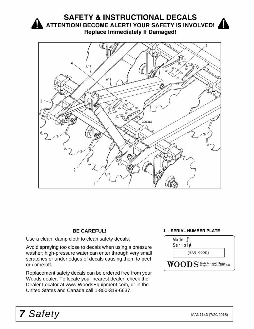
BE CAREFUL!
Use a clean, damp cloth to clean safety decals.
Avoid spraying too close to decals when using a pressure washer; high-pressure water can enter through very small scratches or under edges of decals causing them to peel or come off.
Replacement safety decals can be ordered free from your Woods dealer. To locate your nearest dealer, check the Dealer Locator at www.WoodsEquipment.com, or in the United States and Canada call 1-800-319-6637.
1 - SERIAL NUMBER PLATE
SAFETY & INSTRUCTIONAL DECALSATTENTION! BECOME ALERT! YOUR SAFETY IS INVOLVED!
Replace Immediately If Damaged!

Safety 8MAN1143 (7/20/2015)
2 - PN 10210694 - PN 1006885 3 - PN 1021070
5 - REAR RED REFLECTOR (PN 20106) Located on rear of frame (DHS64) (Not Shown).
6 - REAR RED REFLECTOR (PN 57123) Located on rear of rear gang tubes (DHS80, DHM80, DHM96) (Not Shown).
7 - FRONT AMBER REFLECTOR (PN 1002940) Located on front of all gang tubes (DHM96) (Not Shown).
8 - SAFETY DECAL SET (PN 1042082) Includes decals 2 - 5 (DHS48, DHS64).
9 - SAFETY DECAL SET (PN 1042085) Includes decals 2 - 4, 6, 7 (DHS80, DHM80, DHM96).
SAFETY & INSTRUCTIONAL DECALSATTENTION! BECOME ALERT! YOUR SAFETY IS INVOLVED!
Replace Immediately If Damaged!
(Rev. 1/20/2016)

9 Operation MAN1143 (7/20/2015)
OPERATION
The operator is responsible for the safe operation ofthis equipment. The operator must be properly trained.Operators should be familiar with the equipment, thetractor, and all safety practices before starting opera-tion. Read the safety rules and safety decals, page 5through page 8.
The Disc Harrow is designed for a wide range of appli-cations: leveling, grading, and discing. Recommendedtractor ground speed for most conditions is from 2 to 6mph.
A minimum 25% of tractor and equipmentweight must be on the tractor front wheels whenattachments are in transport position. Without thisweight, front tractor wheels could raise up result-ing in loss of steering. The weight may be attainedwith front wheel weights, ballast in tires, front trac-tor weights or front loader. Weigh the tractor andequipment. Do not estimate.
Power unit must be equipped with ROPS orROPS cab and seat belt. Keep seat belt securelyfastened. Falling off power unit can result in deathfrom being run over or crushed. Keep foldableROPS system in “locked up” position at all times.
Never allow children or untrained persons tooperate equipment.
Do not allow bystanders in the area when oper-ating, attaching, removing, assembling, or servic-ing equipment.
NEVER GO UNDERNEATH EQUIPMENT. Neverplace any part of the body underneath equipmentor between moveable parts even when the enginehas been turned off. Hydraulic system leak-down,hydraulic system failures, mechanical failures, ormovement of control levers can cause equipmentto drop or rotate unexpectedly and cause severeinjury or death.
• Service work does not require going under-neath implement.• Read Operator's Manual for service instruc-tions or have service performed by a qualifieddealer.
Stop power unit and equipment immediatelyupon striking an obstruction. Turn off engine, setparking brake, remove key, inspect, and repair anydamage before resuming operation.
Always wear relatively tight and belted clothingto avoid getting caught in moving parts. Wearsturdy, rough-soled work shoes and protectiveequipment for eyes, hair, hands, hearing, and head;and respirator or filter mask where appropriate.
PRE-OPERATION CHECK LISTOwner’s Responsibility
___ Review and follow all safety rules and safetydecal instructions, page 5 through page 8.
___ Check all lubrication points and grease asinstructed in lubrication information.
___ Check that equipment is properly and securelyattached to tractor.
___ Check that all safety decals are installed and ingood condition. Replace if damaged.
___ Check that all hardware is properly installedand secured.
___ Do not allow riders.
___ Make sure tractor ROPS or ROPS cab andseat belt are in good condition. Keep seat beltsecurely fastened during operation.
CONNECT DISC HARROW TO TRACTOR
This Disc Harrow should be mounted on tractors withinthe engine horsepower rating specified on page 4. Donot exceed maximum engine horsepower rating for agiven model.
This Disc Harrow is compatible with 3-point tractorsequipped with side swing type lower lift arms. See page4 for 3-point hitch categories for a given model.
Adjust or remove tractor drawbar to eliminate interfer-ence with Disc Harrow.
NOTICE■ The 3/4" bolt and sleeve in the lower hole pro-vide the attachment point for a Category 1 quickcoupler. Do not remove this bolt and sleeve whenoperating the disc harrow.
�������
CAUTION

Operation 10MAN1143 (7/20/2015)
DHS48 - Category 1(See Figure 1)
1. Place tractor 3-point lower lift arms over outer hitchpins (1).
2. Secure with klik pins (2).
3. Attach the tractor’s top link to the top hole of theDisc Harrow frame (3).
4. Secure with the heavy-duty top link pin andretaining pin supplied with the tractor top link.
Figure 1. DHS48 CAT 1 Connection
DHS48 - Quick Hitch (Optional)(CAT 1 Only) (See Figure 2)
The DHS48 Disc Harrow will attach to a Category 1quick hitch.
1. Use Quick Hitch Bushing Kit 1023725 when usinga quick hitch coupler.
2. Place Quick Hitch bushings (2) over mounting pin(1) and secure into position with roll pin (3).
3. Align quick hitch with lower bushings (2) and uppersleeve (4) in the lower hole on top of Disc Harrowframe.
Figure 2. DHS48 Quick Hitch Connection.
DHS48 - Category 0 (Optional)
(See Figure 3)
1. Place tractor 3-point lower lift arms over inner hitchpins (1).
2. Secure with safety pins. (Not provided)
3. Attach the tractor’s top link to the top hole of theDisc Harrow frame (4).
4. Secure with the heavy-duty top link pin andretaining pin supplied with the tractor top link.
Figure 3. DHS48 CAT 0 Connection
DHS48 - CAT 0 / 1 Hitch Pin Kit (Optional)
(1009298) (See Figure 3)
1. Remove existing hitch pins.
2. Place hitch pin (1) through Disc Harrow frame.
3. Secure with lock washer (2) and hex nut (3).
4. Repeat for opposite side.
DHS64, 80 - Category 1(See Figure 4)
1. Place tractor 3-point lower lift arms betweenmounting lugs.
2. Secure with Category 1 hitch pins (1) and klik pins(2).
3. Attach the tractor’s top link to the top hole of theDisc Harrow frame (3).
4. Secure with the heavy-duty top link pin andretaining pin supplied with the tractor top link.
(Rev. 12/1/2015)

11 Operation MAN1143 (7/20/2015)
Figure 4. DHS64 & 80 CAT 1 Connection
DHS64, 80 - Quick Hitch (Optional)(CAT 1 Only) (See Figure 5)
The DHS64 & 80 Disc Harrows will attach to a Cate-gory 1 quick hitch.
1. Use Quick Hitch Bushing Kit 1022043 when usinga quick hitch coupler.
2. Remove lower hitch pins (1) from Disc Harrowframe.
3. Place Quick Hitch bushings (3) over hitch pin (1)and secure into position with klik pin (2).
4. Align Quick Hitch with lower bushings (3) andupper sleeve (4) in the lower hole on top of Discharrow frame.
Figure 5. DHS64 & 80 Quick Hitch Connection
DHM80, 96 - Category 1(See Figure 6)
1. Place tractor 3-point lower lift arms between innermounting lugs.
2. Secure with Category 1 hitch pins (1) and klik pins(2).
3. Attach the tractor’s top link to the middle hole of theDisc Harrow frame (3).
4. Secure with the heavy-duty top link pin andretaining pin supplied with the tractor top link.
Figure 6. DHM80 & 96 CAT 1 & 2 Connection
DHM80, 96 - Category 2(See Figure 6)
1. Place tractor 3-point lower lift arms between outermounting lugs.
2. Use Category 2 bushings (4) (included) over hitchpins (1) and secure with klik pins (2).
3. Attach the tractor’s top link to the top hole of theDisc Harrow frame (5).
4. Secure with heavy-duty top link pin and retainingpin supplied with the tractor top link.
DHM80, 96 - Quick Hitch (Optional)(CAT 1 or CAT 2) (See Figure 7)
NOTE: The DHM80 & 96 Disc Harrows will attachto a Category 1 or Category 2 quick hitch.
1. Use Quick Hitch Bushing Kit 1022043 when usinga quick hitch coupler.
2. Remove lower hitch pins (1) from Disc Harrowframe.
(Rev. 12/1/2015)

Operation 12MAN1143 (7/20/2015)
3. Place Quick Hitch bushings (3) over hitch pin (1)and secure into position with klik pin (2).
4. Align Quick Hitch with lower bushings (3) andupper sleeve (4) in the lower hole on top of DiscHarrow frame.
Figure 7. DHM80 & 96 Quick Hitch Connection
DISC HARROW ATTITUDE ADJUSTMENT
The attitude of the Disc Harrow is leveled by adjustingthe length of the tractor’s top link.
For best results, always maintain a level disc attitude.A level disc attitude will leave a slight ridge of material,in the center, behind the rear gangs. A large ridge ofmaterial will require the attitude to be adjusted forward.A furrow, in the center, behind the rear gangs willrequire the attitude to be adjusted to the rear.
NOTICE
■ Excessive forward or rear attitude adjustmentwill lead to poor finish and may cause equipmentdamage or premature bearing failure.
ANGLING DISC BLADES
All disc gangs are independently adjustable with 4positions between 0 and 21 degrees. The disc settingbecomes more aggressive with increased gang angle.The greater the disc angle, the greater the material turnover. Adjustments can be made to the disc gang anglesby following these instructions:
1. Using the tractor’s 3-point lift; raise Disc Harrow offthe ground.
2. Remove pin (1) and safety pin.
3. Grasp gang tube and move gang assembly to thedesired position.
4. Insert pin (1) and secure with safety pin.
Figure 8. Angling Blades
NOTE: Guide bolt (2) and washer (3) should beretained with lock nut (4) just loose enough to allowgang angle adjustment. For extended use in oneposition, the guide bolt and lock nut can be tight-ened to provide additional rigidity.
NOTICE
■ Although front and rear gang sets can beadjusted independently, right and left gangs shouldalways be adjusted to the same angle.
STORAGE
To help prevent injury caused by a falling imple-ment, always detach on a hard level surface.
Block equipment securely for storage.
Do not climb or lean on stored equipment.
Keep children and bystanders away from stor-age area.
�������

Service 13MAN1143 (7/20/2015)
SERVICE
The information in this section is written for operatorswho possess basic mechanical skills. If you need help,your dealer has trained service technicians available.For your protection, read and follow the safety informa-tion in this manual.
NEVER GO UNDERNEATH EQUIPMENT. Neverplace any part of the body underneath equipmentor between moveable parts even when the enginehas been turned off. Hydraulic system leak-down,hydraulic system failures, mechanical failures, ormovement of control levers can cause equipmentto drop or rotate unexpectedly and cause severeinjury or death.
• Service work does not require going under-neath.• Read Operator's Manual for service instruc-tions or have service performed by a qualifieddealer.
Keep all persons away from operator controlarea while performing adjustments, service, ormaintenance.
Before performing any service or maintenance,lower attachment to ground, turn off engine, setparking brake, and remove key.
Make sure attachment is properly secured,adjusted, and in good operating condition.
Never perform service or maintenance withengine running.
Tighten all bolts, nuts, and screws to torquechart specifications. Check that all cotter pins areinstalled securely to ensure equipment is in a safecondition before putting unit into service.
Make sure all safety decals are installed.Replace if damaged. (See Safety Decals section forlocation.)
If you do not understand any part of this manualand need assistance, see your dealer.
Always wear relatively tight and belted clothingto avoid getting caught in moving parts. Wearsturdy, rough-soled work shoes and protectiveequipment for eyes, hair, hands, hearing, and head;and respirator or filter mask where appropriate.
LUBRICATION
The DHM80 & 96 are the only Disc Harrows thatrequire lubrication. The DHM80 & 96 disc gang axlebearings should be greased after every 80 hours ofnormal operation. Severe or unusual conditions mayrequire more frequent lubrication.
Do not let excess grease collect on or around parts,particularly when operating in sandy areas.
Use a lithium grease of #2 consistency with a MOLY(molybdenum disulfide) additive for all locations. Besure to clean fittings thoroughly before attachinggrease gun. One good pump of most guns is sufficientwhen lubrication schedule is followed.
NOTICE
■ Do not use excessive amounts of grease onaxle bearings. Excessive amounts of grease cancause seal damage and/or premature bearing fail-ure.
DISC & BEARING REPLACEMENT
Disassemble Gang
1. Lower Disc Harrow to ground.
2. Securely block tractor to prevent wheel rotation.
3. Remove carriage bolts (1) and nuts (2) from allbearings on disc harrow gang.
4. Remove gang assembly from bearing hangers byraising 3-point lift on tractor.
5. With gang assembly removed from bearinghangers, remove outer jam nut (3), inner jam nut(3), washer(s) (4), and endcap (5).
6. Slide discs, spacers, washers and bearings off axleas needed to replace desired disc(s) andbearing(s).
NOTE: Maintain proper order of discs, spacers,washers and bearings for reassembly. (See PartsSection Page 19).
�������
CAUTION

14 Service MAN1143 (7/20/2015)
Figure 9. Disc and Bearing Replacement
Assemble Gang
1. Reassemble gang with new disc(s) and bearing(s)in reverse order of disassembly steps.
NOTE: Maintain proper order of discs, spacers,washers, and bearings for reassembly. (See Parts
Section Page 20).
2. Install endcap, washer(s) and inner jam nut.
Torque inner jam nut to 365 lbs-ft. for 1” thread(DHS48, 64, 80) and 450 lbs-ft for 1-1/8” thread(DHM80 & 96).
3. Install outer jam nut. Torque outer jam nut to 365lbs-ft for 1” thread (DHS48, 64, 80) and 450 lbs-ftfor 1-1/8” thread (DHM80 & 96).
4. Align bearings with bearing hangers. Lower DiscHarrow.
5. Install carriage bolts and nuts on all bearings.
CLEANING
After Each Use
● Remove large debris such as clumps of dirt, grass,crop residue, etc. from machine.
● Inspect machine and replace worn or damagedparts.
● Replace any safety decals that are missing or notreadable.
Periodically or Before Extended Storage
● Clean large debris such as clumps of dirt, grass,crop residue, etc. from machine.
● Remove the remainder using a low-pressure waterspray.
1. Be careful when spraying near scratched or tornsafety decals or near edges of decals as waterspray can peel decal off surface.
2. Be careful when spraying near chipped orscratched paint as water spray can lift paint.
3. If a pressure washer is used, follow the advice ofthe pressure washer manufacturer.
● Inspect machine and replace worn or damagedparts.
● Sand down scratches and the edges of areas miss-ing paint and coat with Woods spray paint ofmatching color (purchase from your Woodsdealer).
● Replace any safety decals that are missing or notreadable (supplied free by your Woods dealer).See Safety Decals section for location drawing.
Assembly 15MAN1143 (7/20/2015)
ASSEMBLY INSTRUCTIONS
DEALER SET-UP INSTRUCTIONS
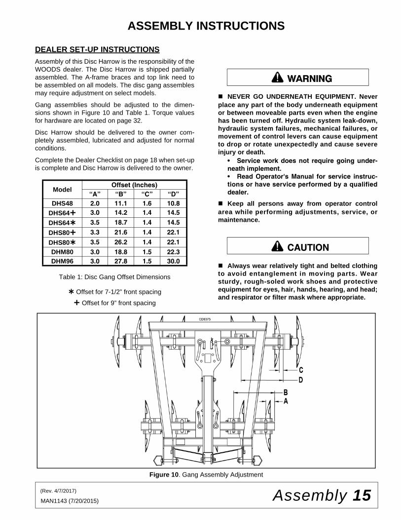
Assembly of this Disc Harrow is the responsibility of theWOODS dealer. The Disc Harrow is shipped partiallyassembled. The A-frame braces and top link need tobe assembled on all models. The disc gang assemblesmay require adjustment on select models.
Gang assemblies should be adjusted to the dimen-sions shown in Figure 10 and Table 1. Torque valuesfor hardware are located on page 32.
Disc Harrow should be delivered to the owner com-pletely assembled, lubricated and adjusted for normalconditions.
Complete the Dealer Checklist on page 18 when set-upis complete and Disc Harrow is delivered to the owner.
Table 1: Disc Gang Offset Dimensions
Offset for 7-1/2” front spacing
Offset for 9” front spacing
NEVER GO UNDERNEATH EQUIPMENT. Neverplace any part of the body underneath equipmentor between moveable parts even when the enginehas been turned off. Hydraulic system leak-down,hydraulic system failures, mechanical failures, ormovement of control levers can cause equipmentto drop or rotate unexpectedly and cause severeinjury or death.
• Service work does not require going under-neath implement.• Read Operator's Manual for service instruc-tions or have service performed by a qualifieddealer.
Keep all persons away from operator controlarea while performing adjustments, service, ormaintenance.
Always wear relatively tight and belted clothingto avoid entanglement in moving parts. Wearsturdy, rough-soled work shoes and protectiveequipment for eyes, hair, hands, hearing, and head;and respirator or filter mask where appropriate.
Figure 10. Gang Assembly Adjustment
ModelOffset (Inches)
“A” “B” “C” “D”DHS48 2.0 11.1 1.6 10.8
DHS64 3.0 14.2 1.4 14.5
DHS64 3.5 18.7 1.4 14.5
DHS80 3.3 21.6 1.4 22.1
DHS80 3.5 26.2 1.4 22.1
DHM80 3.0 18.8 1.5 22.3DHM96 3.0 27.8 1.5 30.0
�������
CAUTION
(Rev. 4/7/2017)

16 Assembly MAN1143 (7/20/2015)
The Disc Harrow is to be assembled by following these instructions:
1. Loosen or remove bolt, washers, and lock nutattaching A-frame brace to Disc Harrow frame.
2. Rotate A-frame brace into upward position andreinstall bolt, washer, and lock nut but do nottighten.
3. Remove bolt, washers , and lock nut from forwardhole on top link where attached to Disc Harrowframe.
4. Move top link forward and reinstall bolt, washers,and lock nut in rear hole on top link throughlug/sleeve on Disc Harrow frame but do not tighten.
5. Remove bolt, washers, sleeve, and lock nutholding A-frame braces together.
6. Align front hole in top link with lower hole at the topof A-frame braces. Reinstall bolt, washers, sleeve,and lock nut through top link and A-frame braces.
7. Tighten all hardware on hitch. Torque values forhardware are located on page 32.
8. Adjust disc gang assembly location per Table 1 onPage 15 if necessary.
9. Fully test all gang adjustments.
10. Complete Dealer Checklist before delivery tocustomer.
ACCESSORY INSTALLATION
All Disc Harrow factory accessories include all neces-sary hardware for installation. Assemble and install fac-tory accessories by following these instructions.
Mud Scrapers
NOTE: Mounting brackets must be installed inproper orientation to achieve maximum adjustabil-ity. See detailed model specific assembly picturesincluded with each kit for more information.
1. Install mounting brackets (1) on bearing hangerswith carriage bolts (2) and lock nuts (3).
2. Install front and rear scraper bars (4 & 5) tomounting brackets (1).
3. Install right facing scraper blades (6) on front leftand rear right scraper bars.
4. Install left facing scraper blades (7) on front rightand rear left scraper bars.
5. Adjust mud scrapers to desired spacing.Adjustments can be made to the scraper bar oreach individual scraper to achieve desired setting.
Figure 11. Mud Scraper Installation
Furrow Fillers
Furrow Fillers - DHS64 & 80
1. Remove and discard originally equipped bumperwashers (1) on rear gangs and replace with slottedbumper washers (2) using Disc and BearingReplacement instructions on page 13.
2. Install furrow filler mount (3) on bumper washerusing carriage bolts (4) and lock nuts (5).
3. Slide disc blade (6) over mount and retain withwasher (7) and lock nut (8).
4. Install and adjust furrow filler mud scraper bar (ifequipped).
5. Tighten all hardware on furrow filler. Torque valuesfor hardware are located on page 32.
Figure 12. Furrow Filler Installation (DHS64 & 80)
Assembly 17MAN1143 (7/20/2015)
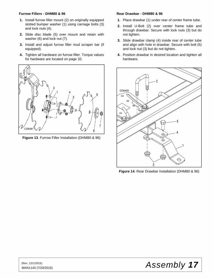
Furrow Fillers - DHM80 & 96
1. Install furrow filler mount (2) on originally equippedslotted bumper washer (1) using carriage bolts (3)and lock nuts (4).
2. Slide disc blade (5) over mount and retain withwasher (6) and lock nut (7).
3. Install and adjust furrow filler mud scraper bar (ifequipped).
4. Tighten all hardware on furrow filler. Torque valuesfor hardware are located on page 32.
Figure 13. Furrow Filler Installation (DHM80 & 96)
Rear Drawbar - DHM80 & 96
1. Place drawbar (1) under rear of center frame tube.
2. Install U-Bolt (2) over center frame tube andthrough drawbar. Secure with lock nuts (3) but donot tighten.
3. Slide drawbar clamp (4) inside rear of center tubeand align with hole in drawbar. Secure with bolt (5)and lock nut (3) but do not tighten.
4. Position drawbar in desired location and tighten allhardware.
Figure 14. Rear Drawbar Installation (DHM80 & 96)
(Rev. 12/1/2015)

18 Dealer Check Lists MAN1143 (7/20/2015)
DEALER CHECK LISTS
PRE-DELIVERY CHECK LIST(DEALER’S RESPONSIBILITY)
Inspect the equipment thoroughly after assembly toensure it is set up properly before delivering it to thecustomer.
The following check lists are a reminder of points toinspect. Check off each item as it is found satisfactoryor after proper adjustment is made.
___ Check that all safety decals are installed and ingood condition. Replace if damaged.
___ Check gang assembly offset and adjust asnecessary.
___ Properly attach implement to tractor and makeall necessary adjustments.
___ Check all bolts to be sure they are properlytorqued.
___ Check that all cotter pins and safety pins areproperly installed. Replace if damaged.
___ Check and grease all lubrication points asidentified in lubrication section on page 10.
DELIVERY CHECK LIST(DEALER’S RESPONSIBILITY)
___ Show customer how to make adjustments.
___ Point out the safety decals. Explain their mean-ing and the need to keep them in place and ingood condition. Emphasize the increasedsafety hazards when instructions are not fol-lowed.
___ Present Operator's Manual and request thatcustomer and all operators read it before oper-ating equipment. Point out the manual safetyrules, explain their meanings and emphasizethe increased safety hazards that exist whensafety rules are not followed.
___ For mounted units, add wheel weights, ballastin front tires, and/or front tractor weight toenhance front end stability. A minimum 20% oftractor and equipment gross weight must be onfront tractor wheels. When adding weight toattain 20% of tractor and equipment weight onfront tractor wheels, you must not exceed theROPS weight certification. Weigh the tractorand equipment. Do not estimate!
___ Make customer aware of optional equipmentavailable so that customer can make properchoices as required.
___ Show customer the safe, proper procedures tobe used when mounting, dismounting and stor-ing equipment.
___ Instruct customer how to lubricate the disc har-row and explain the importance of lubrication.
___ Explain to the customer the potential crushinghazards of going underneath raised equip-ment. Service work does not require goingunderneath.

Parts 19MAN1143 (7/20/2015)
PARTS INDEX
DISC HARROW
DHS48, DHS64, DHS80DHM80, DHM96
DHS48 FRAME ASSEMBLY . . . . . . . . . . . . . . . . . . . . . . . . . . . . . . . . . . . . . . . . . . . . . . . . . . . . . . 20
DHS48 GANG ASSEMBLY . . . . . . . . . . . . . . . . . . . . . . . . . . . . . . . . . . . . . . . . . . . . . . . . . . . . . . . 21
DHS64 & DHS80 FRAME ASSEMBLY . . . . . . . . . . . . . . . . . . . . . . . . . . . . . . . . . . . . . . . . . . . . . . 22
DHS64 & DHS80 FRONT GANG ASSEMBLY. . . . . . . . . . . . . . . . . . . . . . . . . . . . . . . . . . . . . . . . . 23
DHS64 & DHS80 REAR GANG ASSEMBLY . . . . . . . . . . . . . . . . . . . . . . . . . . . . . . . . . . . . . . . . . . 24
DHM80 & DHM96 FRAME ASSEMBLY. . . . . . . . . . . . . . . . . . . . . . . . . . . . . . . . . . . . . . . . . . . . . . 25
DHM80 & DHM96 FRONT GANG ASSEMBLY . . . . . . . . . . . . . . . . . . . . . . . . . . . . . . . . . . . . . . . . 26
DHM80 & DHM96 REAR GANG ASSEMBLY . . . . . . . . . . . . . . . . . . . . . . . . . . . . . . . . . . . . . . . . . 27
DHS & DHM MUD SCRAPER ASSEMBLY (OPTIONAL) . . . . . . . . . . . . . . . . . . . . . . . . . . . . . . . . 28
DHS64 & DHS80 FURROW FILLER ASSEMBLY (OPTIONAL) . . . . . . . . . . . . . . . . . . . . . . . . . . . 29
DHM80 & DHM96 FURROW FILLER ASSEMBLY (OPTIONAL) . . . . . . . . . . . . . . . . . . . . . . . . . . 30
DHM80 & DHM96 REAR DRAWBAR ASSEMBLY (OPTIONAL) . . . . . . . . . . . . . . . . . . . . . . . . . . 31

20 Parts MAN1143 (7/20/2015)
DHS48 FRAME ASSEMBLY
REF PART QTY DESCRIPTION
1 1041325 1 Disc frame
2 1041311 2 Front gang tube
3 1041312 2 Rear gang tube
4 33661 2 Cat 1 mount pin w/nut & lock washer
5 43627 * 2 7/16 x 2 Klik pin
6 1042106 4 5/8 x 3.0 Bent pin
7 23141 * 4 5/8 NC x 3-1/2 HHCS, GR5
8 3632 * 4 5/8 SAE Flat washer
9 19025 * 4 5/8 NC Flanged lock nut
10 12558 * 2 3/4 NC x 4-1/2 HHCS, GR5
REF PART QTY DESCRIPTION
11 2864 * 6 3/4 SAE Flat washer
12 302207 * 4 3/4 NC Flanged lock nut
13 1002018 2 Sleeve, .81 x 1.25 x 2.12
14 1041327 1 Top link
15 300517 * 2 3/4 NC x 1-3/4 HHCS, GR5
16 1041342 1 Right A-frame
17 1041343 1 Left A-frame
HHCS Hex Head Cap Screw
* Standard hardware, obtain locally
(Rev. 1/08/2018)

Parts 21MAN1143 (7/20/2015)
DHS48 GANG ASSEMBLY(7-1/2" Spacing) (16" Blades)
REF PART QTY DESCRIPTION
1 1040602 4 Disc harrow axle - 1" x 19.0"
2 1042077 4 Bumper washer
3 1038696 12 16" Notched disc blade
4 1011323 8 3-5/8" Half spacer
5 1011324 8 2-3/8" Half spacer
6 1022500 8 Axle bearing - 1"
7 29893 * 32 1/2 NC x 1-1/2 Carriage bolt, GR5
8 11900 * 32 1/2 NC Flanged lock nut
9 1040620 8 U-bolt, 3/4 NC x 3.81 x 3.31
10 302207 * 16 3/4 NC Flanged lock nut
11 1041338 4 Bearing hanger, offset
REF PART QTY DESCRIPTION
12 1041335 4 Bearing hanger
13 1041341 4 Washer, 1.41 x 3.50 x .25
14 1022501 4 1-1/4" End spacer
15 1041321 4 Washer, 1.03 x 1.63 x .25
16 2250 8 1 NC Hex nut
* Standard hardware, obtain locally

22 Parts MAN1143 (7/20/2015)
DHS64 & 80 FRAME ASSEMBLY
REF PART QTY DESCRIPTION
1 1041300 1 Disc frame (DHS64) -or-
1 1041301 1 Disc frame (DHS80)
2 1041344 2 Front gang tube (DHS64) -or-
2 1041345 2 Front gang tube (DHS80)
3 1041313 2 Rear gang tube (DHS64) -or-
3 1041314 2 Rear gang tube (DHS80)
4 SU105 2 Cat 1drawbar pin
5 43627 * 2 7/16 x 2 Klik pin
6 1042106 4 5/8 x 3.0 Bent pin
7 23141 * 4 5/8 NC x 3-1/2 HHCS, GR5
8 3632 * 4 5/8 SAE Flat washer
9 19025 * 4 5/8 NC Flanged lock nut
REF PART QTY DESCRIPTION

Parts 23MAN1143 (7/20/2015)
REF PART QTY DESCRIPTION
10 12558 * 4 3/4 NC x 4-1/2 HHCS, GR5
11 2864 * 6 3/4 SAE Flat washer
12 302207 * 4 3/4 NC Flanged lock nut
13 1002018 2 Sleeve, .81 x 1.25 x 2.12
14 1041303 1 Top link
15 300517 * 2 3/4 NC x 1-3/4 HHCS, GR5
16 1041324 1 Right A-frame
17 1041323 1 Left A-frame
HHCS Hex Head Cap Screw
* Standard hardware, obtain locally

24 Parts MAN1143 (7/20/2015)
DHS64 & 80 FRONT GANG ASSEMBLY(9" Spacing) (18" Blades)
DHS64 DHS80REF PART PART QTY DESCRIPTION
1 1042100 ---------- 2 Disc harrow axle - 1" x 21.5" -or-1 ---------- 1042101 2 Disc harrow axle - 1" x 31.0"2 1042077 1042077 2 Bumper washer3 1011274 (6) 1011274 (8) 18" Notched disc blade4 1042103 1042103 4 5-1/8" Half spacer5 1011324 1011324 4 2-3/8" Half spacer6 1022500 1022500 4 Axle bearing - 1"7 29893* 29893* 16 1/2 NC x 1-1/2 Carriage bolt, GR58 11900* 11900* 16 1/2 NC Flanged lock nut9 1040620 1040620 4 U-Bolt, 3/4 NC x 3.81 x 3.31
10 302207* 302207* 8 3/4 NC Flanged lock nut11 1041315 (2) 1041338 (4) Bearing hanger, straight12 1041318 (2) ---------- Bearing hanger, offset13 ---------- 1042102 (2) 9" Plain spacer14 1022501 1022501 2 1-1/4" End spacer15 1041321 1041321 2 Washer, 1.03 x 1.63 x .2516 2250 2250 4 1NC Hex nut
* Standard Hardware, Obtain Locally
(Rev. 4/7/2017)
Parts 25MAN1143 (7/20/2015)
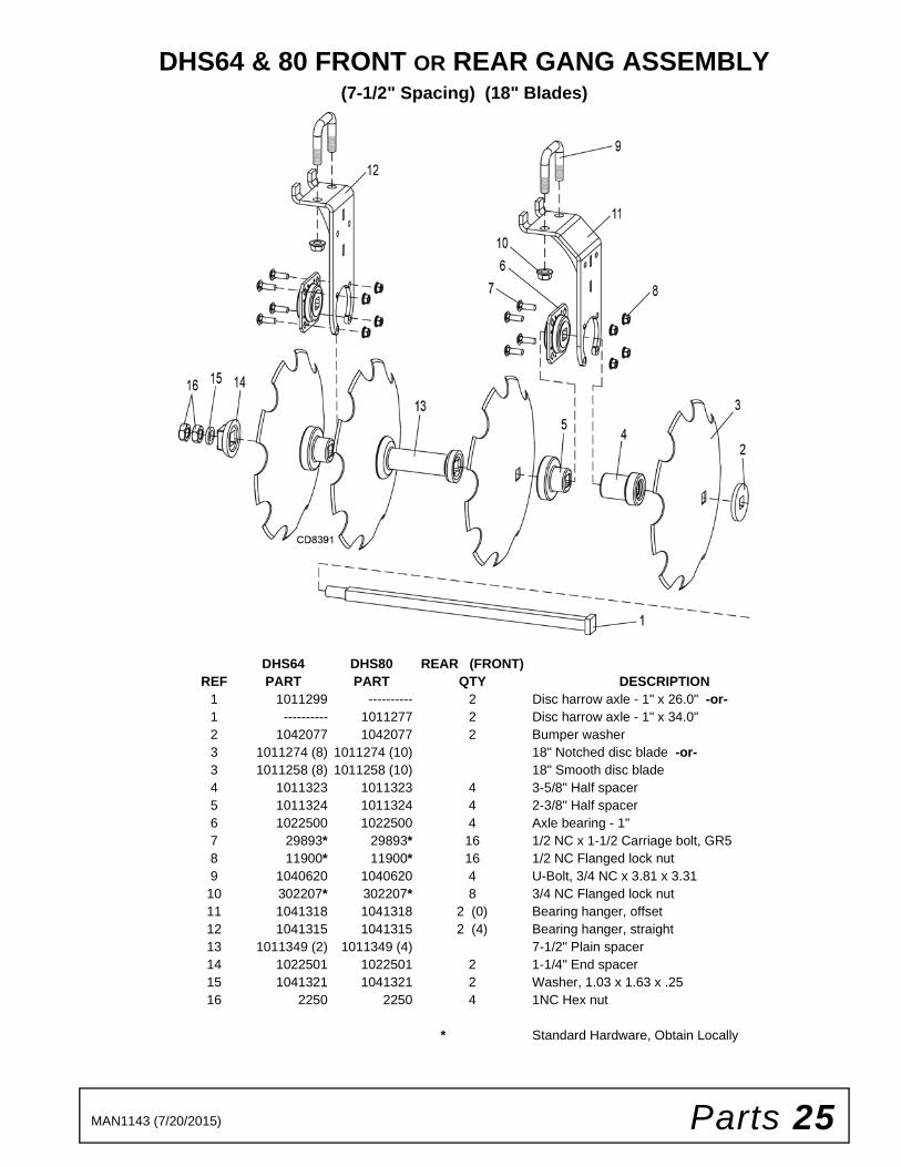
DHS64 & 80 FRONT OR REAR GANG ASSEMBLY(7-1/2" Spacing) (18" Blades)
DHS64 DHS80 REAR (FRONT)REF PART PART QTY DESCRIPTION
1 1011299 ---------- 2 Disc harrow axle - 1" x 26.0" -or-1 ---------- 1011277 2 Disc harrow axle - 1" x 34.0"2 1042077 1042077 2 Bumper washer3 1011274 (8) 1011274 (10) 18" Notched disc blade -or-3 1011258 (8) 1011258 (10) 18" Smooth disc blade4 1011323 1011323 4 3-5/8" Half spacer5 1011324 1011324 4 2-3/8" Half spacer6 1022500 1022500 4 Axle bearing - 1"7 29893* 29893* 16 1/2 NC x 1-1/2 Carriage bolt, GR58 11900* 11900* 16 1/2 NC Flanged lock nut9 1040620 1040620 4 U-Bolt, 3/4 NC x 3.81 x 3.31
10 302207* 302207* 8 3/4 NC Flanged lock nut11 1041318 1041318 2 (0) Bearing hanger, offset12 1041315 1041315 2 (4) Bearing hanger, straight13 1011349 (2) 1011349 (4) 7-1/2" Plain spacer14 1022501 1022501 2 1-1/4" End spacer15 1041321 1041321 2 Washer, 1.03 x 1.63 x .2516 2250 2250 4 1NC Hex nut
* Standard Hardware, Obtain Locally
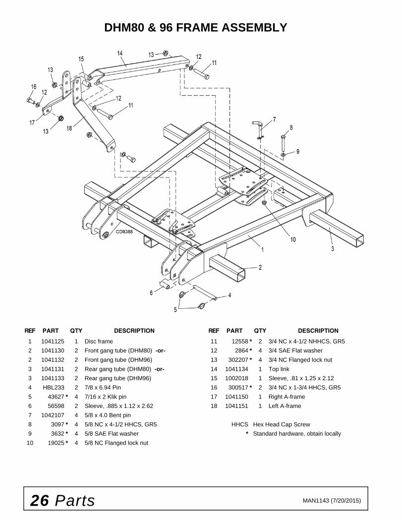
26 Parts MAN1143 (7/20/2015)
DHM80 & 96 FRAME ASSEMBLY
REF PART QTY DESCRIPTION
1 1041125 1 Disc frame
2 1041130 2 Front gang tube (DHM80) -or-
2 1041132 2 Front gang tube (DHM96)
3 1041131 2 Rear gang tube (DHM80) -or-
3 1041133 2 Rear gang tube (DHM96)
4 HBL233 2 7/8 x 6.94 Pin
5 43627 * 4 7/16 x 2 Klik pin
6 56598 2 Sleeve, .885 x 1.12 x 2.62
7 1042107 4 5/8 x 4.0 Bent pin
8 3097 * 4 5/8 NC x 4-1/2 HHCS, GR5
9 3632 * 4 5/8 SAE Flat washer
10 19025 * 4 5/8 NC Flanged lock nut
REF PART QTY DESCRIPTION
11 12558 * 2 3/4 NC x 4-1/2 NHHCS, GR5
12 2864 * 4 3/4 SAE Flat washer
13 302207 * 4 3/4 NC Flanged lock nut
14 1041134 1 Top link
15 1002018 1 Sleeve, .81 x 1.25 x 2.12
16 300517 * 2 3/4 NC x 1-3/4 HHCS, GR5
17 1041150 1 Right A-frame
18 1041151 1 Left A-frame
HHCS Hex Head Cap Screw
* Standard hardware, obtain locally

Parts 27MAN1143 (7/20/2015)
DHM80 & 96 FRONT GANG ASSEMBLY(9" Spacing) (20" Blades)
DHM80 DHM96REF PART PART QTY DESCRIPTION
1 1040601 ---------- 2 Disc harrow axle - 1-1/8" x 31.0" -or-1 ---------- 1040600 2 Disc harrow axle - 1-1/8" x 40.25"2 1038801 1038801 2 Bumper washer3 1038638 (8) 1038638 (10) 20" Notched disc blade4 1038824 1038824 4 4-1/2" Half spacer5 1038641 1038641 4 1-3/4" Half spacer6 1038823 1038823 12 Axle washer, 1-1/8" x 3/8"7 1038645 1038645 4 Axle bearing - 1-1/8"8 29893* 29893* 16 1/2 NC x 1-1/2 Carriage bolt, GR59 11900* 11900* 16 1/2 NC Flanged lock nut
10 1034668 1034668 4 U-Bolt, 3/4 NC x 3.81 x 4.3111 302207* 302207* 8 3/4 NC Flanged lock nut12 1041147 1041147 2 Bearing hanger, offset13 1041144 1041144 2 Bearing hanger, straight14 1038643 (2) 1038643 (4) 9" Plain spacer15 1038640 1038640 2 1-1/4" End spacer16 1038815 1038815 4 1-1/8 NC Hex nut
* Standard Hardware, Obtain Locally
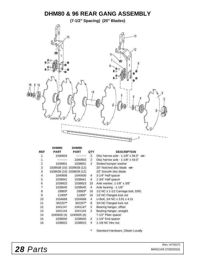
28 Parts MAN1143 (7/20/2015)
DHM80 & 96 REAR GANG ASSEMBLY(7-1/2" Spacing) (20" Blades)
DHM80 DHM96REF PART PART QTY DESCRIPTION
1 1040604 ---------- 2 Disc harrow axle - 1-1/8" x 34.0" -or-1 ---------- 1040603 2 Disc harrow axle - 1-1/8" x 43.0"2 1038801 1038801 2 Slotted bumper washer3 1038638 (10) 1038638 (12) 20" Notched disc blade -or-3 1038639 (10) 1038639 (12) 20" Smooth disc blade4 1040606 1040606 4 3-1/4" Half spacer5 1038641 1038641 4 1-3/4" Half spacer6 1038823 1038823 10 Axle washer, 1-1/8" x 3/8"7 1038645 1038645 4 Axle bearing - 1-1/8"8 29893* 29893* 16 1/2 NC x 1-1/2 Carriage bolt, GR59 11900* 11900* 16 1/2 NC Flanged lock nut
10 1034668 1034668 4 U-Bolt, 3/4 NC x 3.81 x 4.3111 302207* 302207* 8 3/4 NC Flanged lock nut12 1041147 1041147 2 Bearing hanger, offset13 1041144 1041144 2 Bearing hanger, straight14 1040605 (4) 1040605 (6) 7-1/2" Plain spacer15 1038640 1038640 2 1-1/4" End spacer16 1038815 1038815 4 1-1/8 NC Hex nut
* Standard Hardware, Obtain Locally
(Rev. 4/7/2017)
Parts 29MAN1143 (7/20/2015)
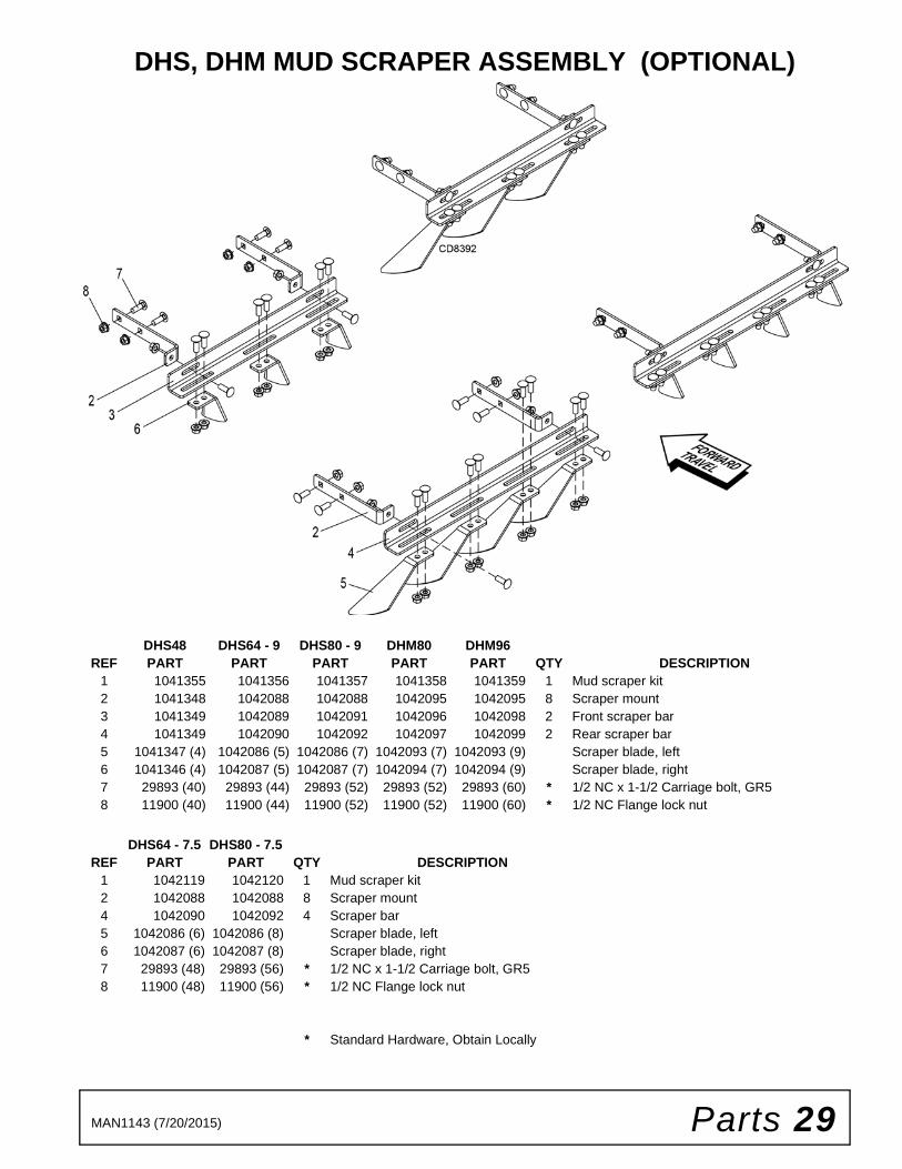
DHS, DHM MUD SCRAPER ASSEMBLY (OPTIONAL)
DHS48 DHS64 - 9 DHS80 - 9 DHM80 DHM96REF PART PART PART PART PART QTY DESCRIPTION
1 1041355 1041356 1041357 1041358 1041359 1 Mud scraper kit2 1041348 1042088 1042088 1042095 1042095 8 Scraper mount3 1041349 1042089 1042091 1042096 1042098 2 Front scraper bar4 1041349 1042090 1042092 1042097 1042099 2 Rear scraper bar5 1041347 (4) 1042086 (5) 1042086 (7) 1042093 (7) 1042093 (9) Scraper blade, left6 1041346 (4) 1042087 (5) 1042087 (7) 1042094 (7) 1042094 (9) Scraper blade, right7 29893 (40) 29893 (44) 29893 (52) 29893 (52) 29893 (60) * 1/2 NC x 1-1/2 Carriage bolt, GR58 11900 (40) 11900 (44) 11900 (52) 11900 (52) 11900 (60) * 1/2 NC Flange lock nut
DHS64 - 7.5 DHS80 - 7.5REF PART PART QTY DESCRIPTION
1 1042119 1042120 1 Mud scraper kit2 1042088 1042088 8 Scraper mount4 1042090 1042092 4 Scraper bar5 1042086 (6) 1042086 (8) Scraper blade, left6 1042087 (6) 1042087 (8) Scraper blade, right7 29893 (48) 29893 (56) * 1/2 NC x 1-1/2 Carriage bolt, GR58 11900 (48) 11900 (56) * 1/2 NC Flange lock nut
* Standard Hardware, Obtain Locally

30 Parts MAN1143 (7/20/2015)
DHS64 & 80 FURROW FILLER ASSEMBLY (OPTIONAL)
REF PART QTY DESCRIPTION1 1041360 1 DHS Furrow filler kit2 1042080 2 Slotted bumper washer3 1041157 2 Furrow filler mount4 29893 * 8 1/2 NC x 1-1/2 Carriage bolt, GR55 11900 * 8 1/2 NC Flanged lock nut6 1039084 2 Furrow filler washer7 302207 * 2 3/4 NC Flanged lock nut8 1041189 1 Furrow filler scraper, left hand9 1041190 1 Furrow filler scraper, right hand
1039919KT 1 16" Notched disc blades, pair(Not included - order separately)
* Standard Hardware, Obtain Locally

Parts 31MAN1143 (7/20/2015)
DHM80 & 96 FURROW FILLER ASSEMBLY (OPTIONAL)
REF PART QTY DESCRIPTION1 1041361 1 DHM Furrow filler kit2 1041157 2 Furrow filler mount3 12735 * 8 1/2 NC x 1-3/4 Carriage bolt, GR54 11900 * 8 1/2 NC Flanged lock nut5 1039084 2 Furrow filler washer6 302207 * 2 3/4 NC Flanged lock nut7 1041179 1 Furrow filler scraper, left hand8 1041180 1 Furrow filler scraper, right hand
1039919KT 1 16" Notched disc blades, pair(Not included - order separately)
-or- -or-1039920KT 1 18" Notched disc blades, pair
(Not included - order separately)
* Standard Hardware, Obtain Locally
(Rev. 12/1/2015)

32 Parts MAN1143 (7/20/2015)
DHM80 & 96 REAR DRAWBAR ASSEMBLY (OPTIONAL)
REF PART QTY DESCRIPTION1 1041362 1 DHM Rear drawbar kit2 1041366 1 Drawbar3 1034668 1 U-Bolt, 3/4 NC 3.81 x 4.314 302207 * 3 3/4 NC Flanged lock nut5 1041367 1 Drawbar clamp6 735 * 1 3/4 NC x 2 Hex head cap screw, GR5
* Standard Hardware, Obtain Locally

Bolt Torque & Size Charts (Rev. 3/28/2007)32 Appendix
BOLT TORQUE CHARTAlways tighten hardware to these values unless a different torque value or tightening procedure is listed for a specific application.
Fasteners must always be replaced with the same grade as specified in the manual parts list.
Always use the proper tool for tightening hardware: SAE for SAE hardware and Metric for metric hardware.
Make sure fastener threads are clean and you start thread engagement properly.
All torque values are given to specifications used on hardware defined by SAE J1701 MAR 99 & J1701M JUL 96.
Diameter (Inches)
WrenchSize
MARKING ON HEAD
SAE 2 SAE 5 SAE 8
lbs-ft N-m lbs-ft N-m lbs-ft N-m
1/4" 7/16" 6 8 10 13 14 18
5/16" 1/2" 12 17 19 26 27 37
3/8" 9/16" 23 31 35 47 49 67
7/16" 5/8" 36 48 55 75 78 106
1/2" 3/4" 55 75 85 115 120 163
9/16" 13/16" 78 106 121 164 171 232
5/8" 15/16" 110 149 170 230 240 325
3/4" 1-1/8" 192 261 297 403 420 569
7/8" 1-5/16" 306 416 474 642 669 907
1" 1-1/2" 467 634 722 979 1020 1383
Diameter & Thread Pitch (Millimeters)
Wrench Size
Coarse Thread Fine Thread
Diameter & Thread Pitch (Millimeters)
Marking on Head Marking on Head
Metric 8.8 Metric 10.9 Metric 8.8 Metric 10.9
N-m lbs-ft N-m lbs-ft N-m lbs-ft N-m lbs-ft
6 x 1.0 10 mm 8 6 11 8 8 6 11 8 6 x 1.0
8 x 1.25 13 mm 20 15 27 20 21 16 29 22 8 x 1.0
10 x 1.5 16 mm 39 29 54 40 41 30 57 42 10 x 1.25
12 x 1.75 18 mm 68 50 94 70 75 55 103 76 12 x 1.25
14 x 2.0 21 mm 109 80 151 111 118 87 163 120 14 x 1.5
16 x 2.0 24 mm 169 125 234 173 181 133 250 184 16 x 1.5
18 x 2.5 27 mm 234 172 323 239 263 194 363 268 18 x 1.5
20 x 2.5 30 mm 330 244 457 337 367 270 507 374 20 x 1.5
22 x 2.5 34 mm 451 332 623 460 495 365 684 505 22 x 1.5
24 x 3.0 36 mm 571 421 790 583 623 459 861 635 24 x 2.0
30 x 3.0 46 mm 1175 867 1626 1199 1258 928 1740 1283 30 x 2.0
A
SAE SERIES TORQUE CHART
SAE Bolt Head Identification
SAE Grade 2(No Dashes)
SAE Grade 5(3 Radial Dashes)
SAE Grade 8(6 Radial Dashes)
A
METRIC SERIES TORQUE CHART
Metric Bolt Head Identification
8.8
MetricGrade 10.9
10.9
MetricGrade 8.8
A
A A
Typical Washer Installations Lock Washer
Flat Washer
8/9/00
Bolt

Appendix 33Bolt Torque & Size Charts (Rev. 3/28/2007)
BOLT SIZE CHARTNOTE: Chart shows bolt thread sizes and corresponding head (wrench) sizes for standard SAE and metric bolts.
ABBREVIATIONSAG .............................................................. Agriculture
ASABE ....................American Society of Agricultural & Biological Engineers (formerly ASAE)
ASAE....... American Society of Agricultural Engineers
ATF............................... Automatic Transmission Fluid
BSPP.............................British Standard Pipe Parallel
BSPTM ................British Standard Pipe Tapered Male
CV ....................................................Constant Velocity
CCW.............................................. Counter-Clockwise
CW .............................................................. Clockwise
F .......................................................................Female
FT .............................................................. Full Thread
GA .....................................................................Gauge
GR (5, etc.) ........................................... Grade (5, etc.)
HHCS ........................................Hex Head Cap Screw
HT........................................................... Heat-Treated
JIC ..............................Joint Industry Council 37° Flare
LH.................................................................Left Hand
LT ...........................................................................Left
m ........................................................................ Meter
mm ............................................................... Millimeter
M ..........................................................................Male
MPa......................................................... Mega Pascal
N ......................................................................Newton
NC...................................................... National Coarse
NF ...........................................................National Fine
NPSM.....................National Pipe Straight Mechanical
NPT.......................................... National Pipe Tapered
NPT SWF.........National Pipe Tapered Swivel Female
ORBM ...........................................O-Ring Boss - Male
P........................................................................... Pitch
PBY...................................................... Power-Beyond
psi ......................................... Pounds per Square Inch
PTO.....................................................Power Take Off
QD.................................................... Quick Disconnect
RH.............................................................. Right Hand
ROPS........................... Roll-Over Protective Structure
RPM ........................................Revolutions Per Minute
RT ........................................................................Right
SAE..........................Society of Automotive Engineers
UNC ..................................................... Unified Coarse
UNF...........................................................Unified Fine
UNS ..................................................... Unified Special
5/16 3/8 1/2 5/8 3/4 7/8SAE Bolt Thread Sizes
MM 25 50 75 100 125 150 175
IN 1 7
Metric Bolt Thread Sizes8MM 18MM14MM12MM10MM 16MM
2 3 4 5 6

F-8494 (Rev. 1/3/2017)
©2017 Woods Equipment Company. All rights reserved. Woods® and the Woods logo are trademarks of Woods Equipment Company. All othertrademarks, trade names, or service marks not owned by Woods Equipment Company that appear in this manual are the property of their respectivecompanies or mark holders. Specifications subject to change without notice.
WOODS®| A Blount International Brand2606 South Illinois Route 2 Post Office Box 1000Oregon, Illinois 61061 USA
800-319-6637 tel800-399-6637 faxwoodsequipment.com
WARRANTY(Replacement Parts For All Models Except Mow’n MachineTM
Zero-Turn Mowers and Woods BoundaryTM Utility Vehicles)
Woods Equipment Company (“WOODS”) warrants this product to be free from defect in material andworkmanship for a period of ninety (90) days from the date of delivery of the product to the original purchaserwith the exception of V-belts, which will be free of defect in material and workmanship for a period of 12 months.
Under no circumstances will this Warranty apply in the event that the product, in the good faith opinion ofWOODS, has been subjected to improper operation, improper maintenance, misuse, or an accident. This Warrantydoes not cover normal wear or tear, or normal maintenance items.
This Warranty is extended solely to the original purchaser of the product. Should the original purchaser sell orotherwise transfer this product to a third party, this Warranty does not transfer to the third party purchaser in anyway. There are no third party beneficiaries of this Warranty.
WOODS’ obligation under this Warranty is limited to, at WOODS’ option, the repair or replacement, free ofcharge, of the product if WOODS, in its sole discretion, deems it to be defective or in noncompliance with thisWarranty. The product must be returned to WOODS with proof of purchase within thirty (30) days aftersuch defect or noncompliance is discovered or should have been discovered, routed through the dealer anddistributor from whom the purchase was made, transportation charges prepaid. WOODS shall completesuch repair or replacement within a reasonable time after WOODS receives the product. THERE ARE NOOTHER REMEDIES UNDER THIS WARRANTY. THE REMEDY OF REPAIR OR REPLACEMENT IS THESOLE AND EXCLUSIVE REMEDY UNDER THIS WARRANTY.
THERE ARE NO WARRANTIES WHICH EXTEND BEYOND THE DESCRIPTION ON THE FACE OF THISWARRANTY. WOODS MAKES NO OTHER WARRANTY, EXPRESS OR IMPLIED, AND WOODSSPECIFICALLY DISCLAIMS ANY IMPLIED WARRANTY OF MERCHANTABILITY AND/OR ANYIMPLIED WARRANTY OF FITNESS FOR A PARTICULAR PURPOSE.
WOODS shall not be liable for any incidental or consequential losses, damages or expenses, arising directlyor indirectly from the product, whether such claim is based upon breach of contract, breach of warranty,negligence, strict liability in tort or any other legal theory. Without limiting the generality of the foregoing,Woods specifically disclaims any damages relating to (i) lost profits, business, revenues or goodwill; (ii) loss ofcrops; (iii) loss because of delay in harvesting; (iv) any expense or loss incurred for labor, supplies, substitutemachinery or rental; or (v) any other type of damage to property or economic loss.
This Warranty is subject to any existing conditions of supply which may directly affect WOODS’ ability to obtainmaterials or manufacture replacement parts.
No agent, representative, dealer, distributor, service person, salesperson, or employee of any company, includingwithout limitation, WOODS, its authorized dealers, distributors, and service centers, is authorized to alter, modify,or enlarge this Warranty.
Answers to any questions regarding warranty service and locations may be obtained by contacting:

F-3079 (Rev. 7/31/2017)
WOODS®| A Blount International Brand2606 South Illinois Route 2 Post Office Box 1000Oregon, Illinois 61061 USA
800-319-6637 tel800-399-6637 faxwoodsequipment.com
WARRANTYAll Models Except Mow’n MachineTM Zero-Turn Mowers
Please Enter Information Below and Save for Future Reference.
Date Purchased: ____________________________ From (Dealer): __________________________________________
Model Number: ____________________________ Serial Number: __________________________________________
Woods Equipment Company (“WOODS”) warrants this product to be free from defect in material and workmanship. Except as otherwise set forthbelow, the duration of this Warranty shall be for TWELVE (12) MONTHS COMMENCING ON THE DATE OF DELIVERY OF THEPRODUCT TO THE ORIGINAL PURCHASER.
All current model backhoes, loaders and mounts (except 3-pt. SAF-T-LOK mounts) are warranted for two (2) years from the date of delivery tothe original purchaser. The limited warranty covers any defects in the material and/or workmanship. Following the proper, recommendedinstallation by an authorized Woods Dealer and normal use of a Woods mounting and backhoe or loader, if a tractor incurs damage resulting fromthe attachment, Woods will cover the existing tractor warranty in the event the manufacturer voids its tractor warranty because of the attachment.Warranty does not cover any misuse or abusive conditions that could cause premature wear or damage to attachment or tractor.
The warranty periods for specific parts or conditions are listed below:
Under no circumstances will this Warranty apply in the event that the product, in the good faith opinion of WOODS, has been subjected toimproper operation, improper maintenance, misuse, or an accident. This Warranty does not apply in the event that the product has been materiallymodified or repaired by someone other than WOODS, a WOODS authorized dealer or distributor, and/or a WOODS authorized service center.This Warranty does not cover normal wear or tear, or normal maintenance items. This Warranty also does not cover repairs made with parts otherthan those obtainable through WOODS.
This Warranty is extended solely to the original purchaser of the product. Should the original purchaser sell or otherwise transfer this product to athird party, this Warranty does not transfer to the third party purchaser in any way. There are no third party beneficiaries of this Warranty.
WOODS makes no warranty, express or implied, with respect to engines, batteries, tires or other parts or accessories not manufactured byWOODS. Warranties for these items, if any, are provided separately by their respective manufacturers.
WOODS’ obligation under this Warranty is limited to, at WOODS’ option, the repair or replacement, free of charge, of the product if WOODS, inits sole discretion, deems it to be defective or in noncompliance with this Warranty. The product must be returned to WOODS with proof ofpurchase within thirty (30) days after such defect or noncompliance is discovered or should have been discovered, routed through thedealer and distributor from whom the purchase was made, transportation charges prepaid. WOODS shall complete such repair orreplacement within a reasonable time after WOODS receives the product. THERE ARE NO OTHER REMEDIES UNDER THIS WARRANTY.THE REMEDY OF REPAIR OR REPLACEMENT IS THE SOLE AND EXCLUSIVE REMEDY UNDER THIS WARRANTY.
THERE ARE NO WARRANTIES WHICH EXTEND BEYOND THE DESCRIPTION ON THE FACE OF THIS WARRANTY. WOODSMAKES NO OTHER WARRANTY, EXPRESS OR IMPLIED, AND WOODS SPECIFICALLY DISCLAIMS ANY IMPLIED WARRANTYOF MERCHANTABILITY AND/OR ANY IMPLIED WARRANTY OF FITNESS FOR A PARTICULAR PURPOSE.
WOODS shall not be liable for any incidental or consequential losses, damages or expenses, arising directly or indirectly from theproduct, whether such claim is based upon breach of contract, breach of warranty, negligence, strict liability in tort or any other legaltheory. Without limiting the generality of the foregoing, Woods specifically disclaims any damages relating to (i) lost profits, business, revenuesor goodwill; (ii) loss of crops; (iii) loss because of delay in harvesting; (iv) any expense or loss incurred for labor, supplies, substitute machinery orrental; or (v) any other type of damage to property or economic loss.
This Warranty is subject to any existing conditions of supply which may directly affect WOODS’ ability to obtain materials or manufacturereplacement parts.
No agent, representative, dealer, distributor, serviceperson, salesperson, or employee of any company, including without limitation, WOODS, itsauthorized dealers, distributors, and service centers, is authorized to alter, modify, or
Part or Condition
WarrantedModel Number
Duration (from date of delivery to the original
purchaser)
All units invoiced after 4/30/2012
Gearbox components
BB48X, BB60X, BB72X, BB84X, BB600X, BB720X, BB840X, BB6000X, BB7200X, BB8400X,DS12.50, TS14.60, DS1440, TS1680, DS8.30, DS10.40, DS8.50, DSO8.50, DS10.50, DSO10.50,DBH5.30, DBH6.30
6 yearsBW12, BW15, BW126X, BW180X, BW126XHD, BW180XHD, BW1260X, BW1800XBW10.50, BW10.50Q, BW15.50, BW15.50Q, BW15.60, BW15.60Q, BW10.60, BW10.60Q
BW240X, BW240XHD, BW1620X, BW2400X
RD990X, PRD6000, PRD7200, PRD8400, S15CD, S20CD, S22CD, S25CD, S27CD, S30CD, TC/R74, TC/R68, TC/R60, TBW144, TBW180, TBW204, TSG50, S12ED, S15ED, S18ED, S20ED,TPD25, TPD35, TPD65, TPD95
RDC54, RD60, RD72, TBW150C, TS/R60, TS/R52, TS/R44, RC3.5, RC4, RC5, RC6 3 years (1 year if used in rental or commercial applications)
Blade spindles RD990X, PRD6000, PRD7200, PRD8400, TBW144, TBW180, TBW204 3 years