Director General Health Services, Government of...
433
Construction of Tertiary Care Cancer Centre at Civil Hospital, Ambala Cantt. (HARYANA) Vol-IV- Tech. Specifications Tender No. HITES/IDN/TCCC-AMBL/2018-19 Vol-IV -TS 1 Director General Health Services, Government of Haryana Tender No. HITES/IDN/TCCC-AMBL/2018-19 e-TENDER FOR Construction of Tertiary Care Cancer Centre, Ambala Cantt. (HARYANA) Volume- IV Technical Specifications M/s HLL Infra Tech Services Ltd. (HITES) (Subsidiary of HLL Lifecare Ltd., A Government of India Enterprise) B-14A, Sector – 62, NOIDA (UP) -201307 Phone no: 0120-4071500, Fax no: 0120-4071513 (May, 2018)
Transcript of Director General Health Services, Government of...
Construction of Tertiary Care Cancer Centre at Civil Hospital, Ambala Cantt. (HARYANA) Vol-IV- Tech. Specifications
Tender No. HITES/IDN/TCCC-AMBL/2018-19 Vol-IV -TS 1
Director General Health Services,
Government of Haryana
Tender No. HITES/IDN/TCCC-AMBL/2018-19
e-TENDER
FOR
Construction of Tertiary Care Cancer Centre, Ambala Cantt. (HARYANA)
Volume- IV
Technical Specifications
M/s HLL Infra Tech Services Ltd. (HITES)
(Subsidiary of HLL Lifecare Ltd., A Government of India Enterprise)
B-14A, Sector – 62, NOIDA (UP) -201307
Phone no: 0120-4071500, Fax no: 0120-4071513
(May, 2018)
Construction of Tertiary Care Cancer Centre at Civil Hospital, Ambala Cantt. (HARYANA) Vol-IV- Tech. Specifications
Tender No. HITES/IDN/TCCC-AMBL/2018-19 Vol-IV -TS 2
Director General Health Services, Haryana Government of Haryana,
Construction of Tertiary Care Cancer Centre at Civil Hospital, Ambala Cantt., HARYANA
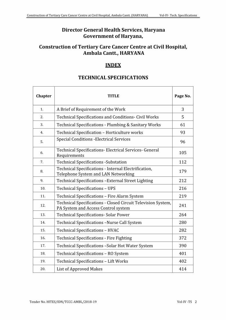
INDEX
TECHNICAL SPECIFICATIONS
Chapter TITLE Page No.
1. A Brief of Requirement of the Work 3
2. Technical Specifications and Conditions- Civil Works 5
3. Technical Specifications - Plumbing & Sanitary Works 61
4. Technical Specification – Horticulture works 93
5. Special Conditions -Electrical Services
96
6. Technical Specifications- Electrical Services- General Requirements
105
7. Technical Specifications -Substation 112
8. Technical Specifications - Internal Electrification, Telephone System and LAN Networking
179
9. Technical Specifications –External Street Lighting 212
10. Technical Specifications – UPS 216
11. Technical Specifications – Fire Alarm System 219
12. Technical Specifications - Closed Circuit Television System, PA System and Access Control system
241
13. Technical Specifications- Solar Power 264
14. Technical Specifications –Nurse Call System 280
15. Technical Specifications – HVAC 282
16. Technical Specifications - Fire Fighting 372
17. Technical Specifications –Solar Hot Water System 390
18. Technical Specifications – RO System 401
19. Technical Specifications – Lift Works 402
20. List of Approved Makes 414
Construction of Tertiary Care Cancer Centre at Civil Hospital, Ambala Cantt. (HARYANA) Vol-IV- Tech. Specifications
Tender No. HITES/IDN/TCCC-AMBL/2018-19 Page 3
Director General Health Services, Haryana Government of Haryana,
Construction of Tertiary Care Cancer Centre at Civil Hospital, Ambala Cantt., HARYANA
TECHNICAL SPECIFICATIONS
CHAPTER-1
A BRIEF OF REQUIREMENT OF THE WORK:
1. General Scope of Work :
The scope of proposed work consists of construction for Tertiary Care Cancer Centre at Civil Hospital, Ambala Cantt., (HARYANA). The building consists of Ground plus Three floors with infrastructure facilities including External Development Works.
The work includes a number of specialized Civil and Plumbing /Electrical / HVAC/ Mechanical / Firefighting System/ Lifts/Electronic services etc.to be executed as integral part of the project.
2. The following are the salient features of the Works:
a. Foundations & other works like underground water tank.
b. Super structure
c. Internal and External water supply, sewerage, Storm water
d. Infrastructure Development i.e. Roads, Parking etc.
e. Electrical Installation ( Internal & External)
f. Comprehensive Fire Fighting/Protection /Alarm System
g. HT< Installation, Substation, DG Sets
h. Comprehensive HVAC
i. Lifts
j. PA, CCTV& Security Systems, EPABX/ Communication Systems, NET/LAN Systems, UPS and BMS
k. Solar energy Systems.
l. Additional works as required in the existing Building& Compound.
3. Appointment of agencies for execution of works mentioned in Para2:
Contractor shall submit credentials of the agencies proposed to be engaged by him/them for execution of sub heads e to k above of works mentioned in Para 2 above to the HITES. Particular agency shall be approved by HITES and only such agencies shall be allowed to execute the work on behalf of the contractor.
In addition to above, the contractor shall get the specialized works including the following works executed through a particular agency, approved by HITES and only such agencies shall be allowed to execute such works on behalf of the contractor.
1. Water proofing treatment works
Construction of Tertiary Care Cancer Centre at Civil Hospital, Ambala Cantt. (HARYANA) Vol-IV- Tech. Specifications
Tender No. HITES/IDN/TCCC-AMBL/2018-19 Page 4
2. Aluminum door and windows, aluminum partition etc.
3. Aluminum composite panel & Structural glazing work
4. Anti-termite chemical treatment
5. Signage
6. Water treatment plant
7. Sewerage treatment plant
8. HT & LT switch gear
9. Air conditioning plants
10. Lifts, escalator and conveyers
11. Gas plants
12. Transformers
13. Diesel generating sets
14. Refrigerator
15. Water coolers
16. Public address systems
17. EPABX system
18. Security System and Alarm
19. Building Automation/ Management System
20. Firefighting
21. CCTV and allied equipment
22. Access control system
23. Bore well
CPWD Specifications for Civil, Electrical and all other works with up to date correction slips for all sub heads of work as applicable, and, Technical Specifications included in the tender documents, wherever applicable.
4. The work shall, in general, conform to the CPWD Specifications for Civil, Electrical and all other works with up to date correction slips for all sub heads of work as applicable, and, Technical Specifications included in the tender documents, wherever applicable. Wherever any aspect of design / construction / material standards is not covered under the above mentioned specification, relevant standards shall be referred to in the order of precedence which shall be as follows. In the case of discrepancy between the Schedule of Quantities, the Specifications and /or the Drawings, the following order of preference shall be observed –
a. Description of Schedule of Quantities
b. Particular specification and Specific Condition, if any
c. Drawings
d. CPWD Specifications
e. Indian Standard Specifications of BIS/ NBC/ IRC/ BS/ ASTM/ DIN
f. For items not covered by any of the above, the work shall be done, as per sound engineering practices and as directed by the Engineer-in-charge.
Construction of Tertiary Care Cancer Centre at Civil Hospital, Ambala Cantt. (HARYANA) Vol-IV- Tech. Specifications
Tender No. HITES/IDN/TCCC-AMBL/2018-19 Page 5
CHAPTER-2
TECHNICAL SPECIFICATIONS AND CONDITIONS- CIVIL WORKS
1. EARTH WORK: As per relevant CPWD specifications.
a. Irrespective of the stipulations in the relevant CPWD Specifications or elsewhere in the Contract, the excavated earth shall be disposed of by the contractor at his own cost to the place as directed by Engineer – in-charge and/or permitted by the local authority after obtaining written permission of the Engineer – in-charge and no payment will be made by the HITES for disposal of this excavated earth.
b. The Contractor shall, at his own expense and without extra charges, make provision for all shoring, pumping, dewatering, dredging or bailing out water, encountered from any sources such as rains, floods, springs, subsoil water table being high or due to any other cause whatsoever. The foundation trenches shall be kept free from water while all the works below ground level are in progress without any extra payment.
c. Filling in plinth shall be consolidated with water and compacted with pneumatic rammers, to achieve 90% relative density on testing. One test is to be carried out for 1000 sq.ms. of compacted area.
2. PLAIN CEMENT CONCRETE AND REINFORCED CEMENT CONCRETE WORK:
A. STONE AGGREGATE:
i. Stone aggregate used in the work shall be of hard broken stone to be obtained from approved source (Quarries to be approved by the Engineer in charge) and shall conform to relevant provision in the Latest CPWD Specifications for works.
B. SAND
i. Sand to be used for the work shall be of as specified in CPWD Specifications 2009. Sand shall be obtained from the source to be got approved by the Engineer in charge and washed if required, with appropriate equipment to bring down the chemical, inorganic and organic impurities within the permissible limits as per the direction of the Engineer in charge. The same shall consist of hard siliceous materials.
Note: Where only one variety of sand is available the sand will be sieved for use in finishing work as directed by the Engineer – in – charge in order to obtain smooth surface and nothing extra will be paid on this account.
ii. Nothing extra shall be paid for screening or washing the sand as prescribed above.
C. FLYASH
Flyash conforming to grade 1 of IS 3812 (Part 1) may be used as part replacement of OPC provided uniform blending with cement is ensured in accordance with clauses 5.2 and 5.2.1 of I.S.456-2000 in the items of BMC and RMC. However this shall not override the provisions of the respective items.
D. CENTERING SHUTTERING AND SCAFFOLDING:
i. All Scaffolding centering for RCC shall be with properly designed system and brought to site well in advance so that the progress of the work is not hampered for non-availability of the same.
ii. All shuttering for RCC work except soffits of slab shall be in water proof shuttering Ply. Shuttering for slab and soffits shall be in water proof shuttering ply or in good quality mild steel plates free of dents, bends or warping and rusting as approved by the Engineer in charge.
Construction of Tertiary Care Cancer Centre at Civil Hospital, Ambala Cantt. (HARYANA) Vol-IV- Tech. Specifications
Tender No. HITES/IDN/TCCC-AMBL/2018-19 Page 6
iii. Contractor should deploy complete one set of shuttering materials for minimum one complete floor and the shuttering material for beam bottom shall be minimum for two complete floors.
E. REINFORCEMENT:
a) TMT reinforcement steel shall be used shall be as per design and conforming to IS: 1786 pertaining to Fe 500D OR Fe 550D grade of steel.
b) TMT steel bars manufactured by main producers, as per list of makes, shall be allowed in the work. Contractor shall produce manufacturer Test Report for each dia and each lot Tests. Nothing extra will be paid for “straightening of bars” received from market in coils or with bends. All incidental charges of any kind whatsoever including cartage, storage, safe custody of materials, cutting and wastage etc. shall be borne by the contractor.
c) The actual average sectional weight for dia up to 10 mm shall be arrived at from one meter long samples (minimum 3 from each dia) taken from each lot of steel. The discretion of the Engineer – in – charge shall be final for the procedure to be followed for determining the average sectional weight of each lot. Quantity of each diameter of steel received at site of work each day will constitute the single lot for this purpose.
d) The weight of each lot of a particular diameter of 10mm and below shall be reckoned as the weight as per actual issue multiplied by a factor equal to the standard sectional weight of the particular diameter divided by the average sectional weight of the particular dia in a particular lot worked out as per above para. Adjustment for the steel shall be effected on the basis of the weight as modified above for quantity payable.
e) Measurement of all diameters of steel be on linear basis and will be converted into weight on the basis of standard sectional weight coefficients given in relevant CPWD specifications mentioned in schedule ‘F’ of General Conditions of Contract.
f) Measurement of reinforcement shall be as per procedure described in the relevant CPWD specifications mentioned in schedule ‘F’ of General Conditions of Contract.
F. Concrete Mix Design
The mix design shall be for MODERATE exposure and GOOD degree of quality control, unless otherwise specified.
G. Concrete Batching Plant (Design Mix)
i. The Concrete Batching Plant of suitable capacity to be installed, as per requirement at site, within a period of 30 days from award of work. The contractor shall install batching plants (preferably within 50 meters distance from the site of work) supplying Concrete at site. The batching plant proposed to be engaged by the contractor shall fulfill the following requirements.
1. It shall be fully computerized.
2. Facility to pump concrete upto the highest point of the building.
3. It should have facility for providing printed advice showing ingredients of concrete carried by each mixer.
4. It should have sufficient capacity to meet the requirement as per schedule.
In case of failure of Batching Plant, RMC may be allowed with a written permission of the Engineer in Charge
ii. Approved admixtures conforming to IS.9103 shall be permitted to be used. The chloride content in the admixture shall satisfy the requirement of BS 5075. The total amount of chloride content in the admixture mixed Concrete shall satisfy the requirement of IS 456-2000.
Construction of Tertiary Care Cancer Centre at Civil Hospital, Ambala Cantt. (HARYANA) Vol-IV- Tech. Specifications
Tender No. HITES/IDN/TCCC-AMBL/2018-19 Page 7
iii. The concrete mix design with and without admixture will be carried out by the contractor through the Laboratories / Test house as approved by Engineer-in-charge.
iv. The various ingredients for mix design \laboratory tests shall be sent to the lab test house through the Engineer and the sample of such ingredients sent shall be preserved at site by the department till completion of work or change in Design Mix whichever is earlier. The sample shall be taken from the approved materials which are proposed to be used in the work.
v. The batching and mixing plant shall be fully automatic.
vi. The contractor has to arrange to erect batching plant for the design mix concrete on his own.
vii. The concrete shall be transported to the site in specially made Transit Mixers & shall have suitable retarders so that it should not set before placing in position. It should have sufficient flow so that at height the concrete shall be placed by pumping only.
viii. Each Transit Mixer reaching site shall invariably have manufacturer’s certificate containing details like truck number Grade of mix, time of leaving the plant, time of reaching a site etc. A copy of the same shall be handed over to E- in – C or his authorized representative.
ix. However samples for testing etc. shall be taken as per the mandatory tests prescribed in latest CPWD specifications.
x. All cubes shall be tested for 7 days and 28 days tests in conformity with the relevant CPWD specifications.
xi. In respect of projected balconies, projected slabs at roof level and projected verandah, the payment for the RCC work shall be made under the items of RCC slabs. Nothing extra shall be paid for the side shuttering at the edges of these projected balconies and projected verandah. All the exposed edge shall however be finished as per specifications and nothing extra shall be paid for this.
xii. In the items of RCC walls, railings and roofs etc. nothing extra shall be paid for making designs as per patterns given by Engineer-in-charges or for thickness of sections.
xiii. The water will be tested with regard to its suitability for use in CC/RCC work and nothing extra will be paid for on this account.
xiv. To receive anchor bolt / foundation for machines to be installed at later date, pocket of size minimum 110x100x300 mm shall be kept while concerting of RCC/ CC members and shall be filled with CC 1:1:2 with plasticizer and as per the direction of Engineer in charge.
H. Ready Mix Concrete (RMC)
i. The contractor shall engage Ready Mix Concrete (RMC) producing plants (Distance of plant from site to be approved by Engineer in Charge) to supply RMC for the work. The RMC plant proposed to be engaged by the contractor shall fulfill the following requirements.
a) It shall be fully computerised.
b) It should have supplied RMC for Govt. projects of similar magnitude.
c) It should have facility for providing printed advice showing ingredients of concrete carried by each mixer.
ii. The Ready Mix Concrete (RMC) producing plants of the main Cement producers shall be preferred.
Construction of Tertiary Care Cancer Centre at Civil Hospital, Ambala Cantt. (HARYANA) Vol-IV- Tech. Specifications
Tender No. HITES/IDN/TCCC-AMBL/2018-19 Page 8
iii. The contractor shall, within 10 days of award of the work submit list of at least three reputed RMC plant companies along with details of such plants Including details of transit mixer, pumps etc. to be deployed indicating name of DGHS/company, its location, capacity, technical establishment, past experience for approval by Engineer-in-charge.
iv. The Engineer-in-Charge reserves the right to exercise check over the:-
a) Ingredients, water and admixtures purchased, stored and to be used in the concrete including conducting of tests for checking quality of materials recordings of test results and declaring the material fit or unfit for use in production of mix.
b) Calibration check of the RMC.
c) Weight and quality check on the ingredient, water and admixture added for batch mixing.
d) Time of mixing of concrete.
e) Testing of fresh concrete, recordings of results and declaring the mix fit or unfit for use. This will include continuous control on the workability during production and taking corrective action.
For exercising such control, the Engineer shall periodically depute his authorized representative at the RMC plant. It shall be the responsibility of the contractor to ensure that the necessary equipment manpower & facilities are made available to Engineer and/or his authorized representative at RMC plant
v. Ingredients, admixtures & water declared unfit for use in production of mix shall not be used. A batch mix found unfit for use shall not be loaded into the truck for transportation.
vi. All required relevant records of RMC shall be made available to the Engineer or his authorized representative. Engineer shall, as required, specify guidelines & additional procedures for quality control & other parameters in respect of materials, production and transportation of concrete mix which shall be binding on the contractor & the RMC plant.
vii. It shall be the responsibility of the Contractor to ensure that the RMC producer provides all necessary testing equipment and takes all necessary measures to ensure Quality control of ready -mixed concrete. In general the required measures shall be:-
a) CONTROL OF PURCHASED MATERIAL QUALITY
RMC producer shall ensure that the materials purchased and used in the production of concrete conform to the stipulation of the relevant agreed standards with the material Supplier and the requirement of the product mix design and quality control producer’s. This shall be accomplished by visual checks, sampling and testing, certification from materials suppliers and information /data from material supplier. Necessary equipment for the testing of all material shall be provided and maintained in calibration condition at the plant by the RMC producer.
b) CONTROL OF MATERIAL STORAGE
Adequate and effective storage arrangement shall be provided by RMC producer at RMC plant for prevention of contamination, reliable transfer and feed system, drainage of aggregates, prevention of freeing or excessive solar heating of Aggregate etc,
c) RECORD OF MIX DESIGN AND MIX DESIGN MODIFICATION
RMC producer shall ensure that record of mix design and mix design modification is available in his computer at RMC plant for inspection of Engineer or his representative at any time.
Construction of Tertiary Care Cancer Centre at Civil Hospital, Ambala Cantt. (HARYANA) Vol-IV- Tech. Specifications
Tender No. HITES/IDN/TCCC-AMBL/2018-19 Page 9
d) COMPUTER PRINT OUTS OF EACH TRUCK LOAD
Each truckload / transit mixer dispatched to site shall carry computer printout of the ingredients of the concrete it is carrying. The printout shall be produced to Engineer or his representative at site before RMC issued in work.
e) TRANSFER AND WEIGHING EOUIPMENT RMC
Producer shall ensure that a documented calibration is in place. Proper calibration records shall be made available indicating date of next calibration due, corrective action taken etc. RMC producer shall ensure additional calibration checks whenever required by the Engineer in writing to contractor. RMC producer shall also maintain a daily production record including details of mixes supplied. Record shall be maintained of what materials were used for that day’s production including water and admixtures.
f) MAINTENANCE OF PLANT, TRUCK Mixers AND PUMPS
Plant, Truck Mixers and Pumps should be well maintained so that it does not hamper any operation of production, transportation and placement.
g) PRODUCTION OF CONCRETE
The following precautions shall be taken during the production of RMC at the plant
i) Weighing (correct reading of batch data and accurate weighing):- For each load, written, printed or graphical records shall be made of the weights of the materials batched, the estimated slump, the total amount of water added to load the delivery tickets number for that load and the time of loading the concrete into the truck.
ii) Visual observation of concrete during production and delivery or during sampling and testing of fresh concrete assessment of uniformity, cohesion, workability adjustment to water content. The workability of the concrete shall be controlled on a continuous basis during production. The batch mix found unfit shall not be loaded into the truck for transportation. Necessary corrective action shall be taken in the production of mix as required for further batches.
iii) Use of adequate equipment at the plant to measure surface moisture content of aggregates, particularly fine aggregates or the workability of the concrete, cube tests etc. shall also be ensured.
iv) Making corresponding adjustment at the plant automatically or manually to batched quantities to allow for observed, measured or reported changes in materials or concrete qualities.
v) Sampling of concrete, testing monitoring of results.
vi) Diagnosis and correction of faults identified from observations /complaints.
The RMC plant produced concrete shall be accepted by Engineer at site after receipt of the same after fulfilling all the requirements of mix mentioned in the tender documents.
viii. The rate for the Item of design mix cement concrete shall be inclusive of all the ingredients including admixtures, if required, labour, machinery T&P etc. (except shuttering which will be measured & paid for separately) required for a design mix concrete of required strength and workability. The rate quoted by the agency shall be net & nothing extra shall be payable on account of change in quantities of concrete, ingredients like cement and aggregates and admixtures etc. as per the approved mix design.
Construction of Tertiary Care Cancer Centre at Civil Hospital, Ambala Cantt. (HARYANA) Vol-IV- Tech. Specifications
Tender No. HITES/IDN/TCCC-AMBL/2018-19 Page 10
ix. Ready mix concrete shall be arranged in quantity as required at site of work. The ready mix concrete shall be supplied as per the pre-agreed schedule approved by Engineer.
x. Frequency of sampling and standards of acceptance shall be as per CPWD specifications.
i) No addition of water or other ingredients shall be permitted in the RMC at site or during transit.
ii) The RMC shall be placed by pump of suitable capacity end the contractor shall arrange sufficient length of pipe at site to place the RMC in the minimum required time. The contractor shall co-ordinate with RMC supplier and pumps hirer to have effective concrete placement.
iii) Pre-paid delivery tickets shall be produced with each truck load of RMC.
iv) The representative of RMC supplier shall attend the site meeting as and when decided by the Engineer
xi. i) The contractor shall assess the quantity of RMC requirement at site well in advance and order accordingly to the RMC supplier. In case excess RMC is received at site, the department shall not be under any obligation to get extra quantities utilized and no payment for such RMC shall be made.
ii) The contractor shall have to employ labour in shifts to ensure continuous casting of raft and other RCC members. No extra payment on this account shall be made.
3. BRICK WORK
a. Bricks used in the work shall be obtained from kilns to be got approved from the Engineer in charge and shall be best quality well burnt ground moulded bricks as available in the vicinity. They shall have a compressive strength of not less than 75 Kgs/sq.cm and an absorption percentage of not more than 15 (Fifteen) % of its dry weight when immersed in water for 24 hours. In all other respects they shall conform to the provision in Latest CPWD Specifications for works.
b. Both the face of wall of thickness more than 23cm shall be kept in the proper plane. Walls of half brick thickness or less shall be measured separately and paid in sqm.
c. Bricks wall beyond half brick thickness shall be measured in multiple of half brick (i.e. more than 115mm or equivalent) which shall be deemed to be inclusive of mortar joints. In all other respects they shall conform to the provision in relevant specifications of the work.
d. For mortar, use of PP Cement shall be preferred.
4. CEMENT PLASTER: - The use of PP Cement shall be preferred.
5. WOOD WORK:
a. Timber required for manufacture of chowkhats and shutters for doors, windows, ventilators, partitions etc shall be Forest Stewardship council (FSC) certified wood and it shall be seasoned and preservative treated.
b. The moisture contents of the wood used in the work shall not be more than that stipulated in the relevant clause of Latest CPWD Specifications for works. The rate quoted for various items shall be inclusive of kiln seasoning and preservative treatment of wood. In all other
Construction of Tertiary Care Cancer Centre at Civil Hospital, Ambala Cantt. (HARYANA) Vol-IV- Tech. Specifications
Tender No. HITES/IDN/TCCC-AMBL/2018-19 Page 11
respects the wood used in the work shall conform to the provision in latest CPWD specification for works.
c. The sample of species to be used shall be deposited by the contractor with the Engineer-in – charge before commencement of the work. The contractor shall produce cash voucher and certificate from standard kiln seasoning plant operator about the timber section to be used on the work having been kiln seasoned by them failing which it would not be so accepted as kiln seasoned.
d. Glass :-
i. Transparent sheet glass (Float glass) conforming to IS 1761 – 1970 shall be used.
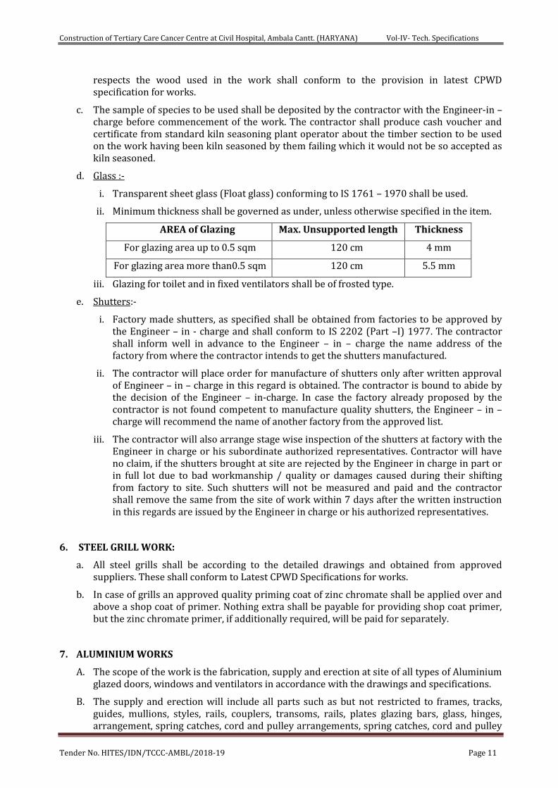
ii. Minimum thickness shall be governed as under, unless otherwise specified in the item.
AREA of Glazing Max. Unsupported length Thickness
For glazing area up to 0.5 sqm 120 cm 4 mm
For glazing area more than0.5 sqm 120 cm 5.5 mm
iii. Glazing for toilet and in fixed ventilators shall be of frosted type.
e. Shutters:-
i. Factory made shutters, as specified shall be obtained from factories to be approved by the Engineer – in - charge and shall conform to IS 2202 (Part –I) 1977. The contractor shall inform well in advance to the Engineer – in – charge the name address of the factory from where the contractor intends to get the shutters manufactured.
ii. The contractor will place order for manufacture of shutters only after written approval of Engineer – in – charge in this regard is obtained. The contractor is bound to abide by the decision of the Engineer – in-charge. In case the factory already proposed by the contractor is not found competent to manufacture quality shutters, the Engineer – in – charge will recommend the name of another factory from the approved list.
iii. The contractor will also arrange stage wise inspection of the shutters at factory with the Engineer in charge or his subordinate authorized representatives. Contractor will have no claim, if the shutters brought at site are rejected by the Engineer in charge in part or in full lot due to bad workmanship / quality or damages caused during their shifting from factory to site. Such shutters will not be measured and paid and the contractor shall remove the same from the site of work within 7 days after the written instruction in this regards are issued by the Engineer in charge or his authorized representatives.
6. STEEL GRILL WORK:
a. All steel grills shall be according to the detailed drawings and obtained from approved suppliers. These shall conform to Latest CPWD Specifications for works.
b. In case of grills an approved quality priming coat of zinc chromate shall be applied over and above a shop coat of primer. Nothing extra shall be payable for providing shop coat primer, but the zinc chromate primer, if additionally required, will be paid for separately.
7. ALUMINIUM WORKS
A. The scope of the work is the fabrication, supply and erection at site of all types of Aluminium glazed doors, windows and ventilators in accordance with the drawings and specifications.
B. The supply and erection will include all parts such as but not restricted to frames, tracks, guides, mullions, styles, rails, couplers, transoms, rails, plates glazing bars, glass, hinges, arrangement, spring catches, cord and pulley arrangements, spring catches, cord and pulley
Construction of Tertiary Care Cancer Centre at Civil Hospital, Ambala Cantt. (HARYANA) Vol-IV- Tech. Specifications
Tender No. HITES/IDN/TCCC-AMBL/2018-19 Page 12
arrangements door closers floor springs etc., required for the whole work whether the parts/ items are individually and specifically referred to in the schedules/ specifications/drawings or not provided that the supply and installation of such parts can be inferred there from and are necessary to make the work complete, unless separate provision is made in the bills of quantities for supply to such parts/items.
C. The doors, windows, ventilators, will be fabricated to suit the finished clear openings in the building/structure which the tenderer will himself measure.
D. Materials:-
i. The members will be made out of aluminum alloy corresponding to IS:733 and will consist of extruded sections and of other shapes, and to sized gauges as shown in the drawings/ described in accordance with the relevant IS codes. The members shall be chosen to provide strength/ stability and maximum resistance to wear and tear.
ii. The Sections will be as per approved makes, extruded sections. As indicated in the drawings the tenderer should specifically mention which sections he is using.
iii. The weight of sections and the corresponding catalogue numbers are mentioned. The IS specifications are to be strictly adhered.
iv. The extruder using recycled materials may be preferred.
v. The alloy of extruded aluminum should be BS or IS old HE9, Alcon 50 SWP. to this effect test certificate has to be provided for the extruder.
E. Finishing:
i. The extruded aluminum section has to be mechanically finished to remove all scratches; extrusion marks etc and subsequently thoroughly cleared in all alkali baths prior to anodizing.
ii. The polyester powder coating, as required, as per item of work, shall be of desired shade with minimum average thickness to 50 microns or other shades as required and to this effect the tenderer must have to produce test certificate from authorized institutions Bureau of Indian Standard.
iii. The polyester powder coated material should be properly wrapped in gummed tape before fabrication to avoid scratches during fabricated and erection shall be kept protected till handing over.
F. Fabrication:
i. Before commencing the fabrication the contractor shall submit to the Engineer – in - charge for their approval detailed shop drawings, based on the Architectural drawings and corresponding specification showing junctions, fittings, accessories such as hinges flush bolts, locks, latches, latching arrangements, peg stays, rotor arms, anodize pivots gaskets rubber packing door felts, mastic, sealant etc., including fixing and sealing arrangements . Type and method of scaffolding he intends to use, Fabrication is to be taken up only after approval by the Engineer – in - charge and in accordance with the approved drawings. Sections for fabrication of door/ window/ventilators etc shall be as per architectural drawings or as approved by the Engineer – in - charge.
ii. A sample of finished door / windows/ ventilator railing etc.shall be fabricated as per the shop drawings approved by the Engineer – in - charge for final approval before under taking mass production/ fabrication,
iii. The doors, window, ventilators and partitions shall be as per thickness given in the approved shop drawings, Polyester Powder coating shall be as specified in the item specifications.
Construction of Tertiary Care Cancer Centre at Civil Hospital, Ambala Cantt. (HARYANA) Vol-IV- Tech. Specifications
Tender No. HITES/IDN/TCCC-AMBL/2018-19 Page 13
iv. All materials shall conform to relevant IS. Codes and in the absence of IS code, they should correspond to the best engineering practice; decision of the the Engineer – in - charge shall be final and binding on the contractor.
v. Fabrication shall be done true to the drawing/ sample approved and in correspondence to the finished openings at the site. All joints shall be mitered at the corners, true right angles, and joints to be finished neatly to hairlines, with concealed fasteners, wherever possible joints shall be made in concealed locations.
vi. All fabricated/finished items shall be packed and carted properly to site to prevent any damage in transit. On receipt at site they shall be carefully stacked in protected storage to avoid distortion/damage.
vii. Site installation shall be with concealed screws, self-tapping or other approved fasteners or may be by welding, due precautions shall be taken to avoid any distortion/ discoloration /damage to the finished items.
viii. Wood work faces /parts coming in contact with masonry shall before shifting to the site be given a heavy coat of alkali resistance bitumen paint. Steel items coming in contact with other incompatible materials shall be given a thick coat of zinc chromate primer.
G. Glazing: Glazing shall be done with flawless sheet glass of best approved quality without waviness, distortion, coloration / discoloration, of specified thickness in sizes as shown in the drawings, fixed as required with special glazing clips, putty, neoprene/PVC gaskets. All glass shall be cleaned thoroughly before they are fixed in position. Unless otherwise specified the minimum thickness shall be 5 mm thick.
8. FIRE CHECK DOORS:-
A. General:-
i. The door shall be procured from approved manufacturer of CPWD / CBRI. The fire and smoke / hot gases check door shall be conforming to IS-3614 (Part-II)). The manufacturer shall have a prototype door tested and certified by CBRI Roorkee, of 120 minutes fire rating confirming to BS : 476 part 22 & IS : 3614 Part II .
ii. The fire and smoke / hot gases check door shall not collapse during the rated period of the fire under the specified fire conditions.
iii. The fire and smoke / hot gases check door shall not allow the passage of hot gases or the flames through the rebate of the gap between the door frame and shutter or through the holes, developed in the shutter during fire.
iv. Material: -Door frames and shutter shall be made from materials specified in the bill of quantities.
v. Shop drawing:- The contractor shall submit including required designing shop drawing for doorframes, shutters complete with
a. Plan, elevation with relative position of adjacent works b. Glazing details with type size and fixing c. Fitting and fixtures with type size, brand and fixing details. d. Finishing details.
vi. Sample Approval:- A sample of fire check door including fittings and fixtures, shall be fabricated as per the shop drawings approved by the Engineer – in - charge for final approval before under taking mass production/ fabrication
B. Wooden Fire Doors & Frames
Construction of Tertiary Care Cancer Centre at Civil Hospital, Ambala Cantt. (HARYANA) Vol-IV- Tech. Specifications
Tender No. HITES/IDN/TCCC-AMBL/2018-19 Page 14
i. Door Frames: - Door frame shall be manufactured from 2nd class teakwood (Ivory Coast) of section as per BOQ. It shall have heat activated intumescent fire seal strip of size 20mm x 4mm (for smoke seal) of approved make provided in grooves on all three sides of the frame. The frame shall be coated with one coat anti-termite fire retardant primer of approved brand. The frame shall be fixed with 8 nos. 100mm dia metal dash fasteners of approved brand and manufacture or as per direction of Engineer-in-charge.
ii. Door Shutter:-
1. The Door shutter shall be of thickness 50 mm minimum but not more than 55mm or as per BOQ, suitable for mounting on the door frame. It shall comprise of two non-combustible boards 12mm to 18 mm thick sandwiching 20 mm to 25 mm fire resistant insulation filler veneered with 3mm thick commercial ply on both faces and pasting of minimum 1 mm thick laminate over wooden fire of approved brand a 100% without Asbestos, Bructile and meerschaum, having density not more than 1150 kg/m3 and thermal conductivity 0.14 W/m K with heat activated intumescent fire seal strip of size 20mm x 4mm of approved mounted in the grooves of teakwood lipping on all sides except bottom.
2. The intumescent sealant shall be used to fill the gaps between board and internal wooden lipping.
3. Vision Panel:- Vision Panel shall be rated vision panels with 6mm thick clear glass (2 hours fire rating) made from Spin turned Rings (380mm dia circular vision panel) or press formed (300mm Square vision panel). Glass shall be fixed with glazing gasket of self-sticking ceramic glass fiber having a classification temperature of 1260o C.
iii. Finish: - The door frame and door shutter shall be finished with minimum to coats of thermo setting acrylic paint for scratch resistance and durability on hard wooden surface (@3.5 sq.mtr. per ltr., per coat) including preparation of base surface as per recommendation of manufacturer to make the surface fire retardant. The paint shall be of approved brand and quality.
iv. Ironmongry Hinges: - Stainless steel ball bearing butt hinges, 3mm thick shall be fixed flushed to the frame and shutter.
C. Metal Fire Doors & Frames: - These shall conform to the BOQ and CPWD specifications.
D. Fire Doors & Fittings
All work is to be carried out in accordance with relevant IS Code and specification for Fire Door & fitting as per IS: 3614 (Part I) – 1966 and direction of Engineer in charge. Door shall be fixed with fire rated hinges 5 Knuckle, 2 bearing butt hinges size 4" x 3" x 3mm, in SS 304 and in satin stainless steel, as per EN 1935, CE Marked. i. Mortice Lock: - 2 hrs, fire rated mortice lock with lever handle tested in accordance
with BS: 476 Part 22.A minimum one year warrantee shall be provided. Mortice sash lock with internal thumb turn and external key operation with lever handles shall be provided.
ii. Flush Bolts (For Double Door):- 300mm concealed extended lever action flush bolts satin finish, fixed to top and bottom of the inactive blade shall be provided.
iii. Automatic Door Closer: - Dual adjustable speed automatic door closer with rack and prinion method, in conformance with BS:476 Part 22 (for fire rating) and BS EN1154 shall be provided. The door closer shall have minimum of one year warrantee.
iv. Pull Handle: 300mm long stainless steel grade 304 D type pull handle shall be fixed with necessary screws etc. complete. A minimum one year warrantee for the product shall be provided.
Construction of Tertiary Care Cancer Centre at Civil Hospital, Ambala Cantt. (HARYANA) Vol-IV- Tech. Specifications
Tender No. HITES/IDN/TCCC-AMBL/2018-19 Page 15
v. Fire Rated Panic exit device: - It shall be suitable for door weights upto 120kgs. The Panic bar as per door leaf (SINGLE LEAF/DOUBLE LEAF) shall consist of Main Panic Latch component, End Component, Push bar, Striker Kit, end caps in Silver finish. Complete set with screws & fixing accessories, External trim, having fire rated door closer TS 71/68 rack and pinion door closer EN size 3/4, with std. arm and with two independent closing valves and latching speed adjustable by arm. Full plastic cover. Silver finish. As per EN 1154 life cycle 500,000 with seals and door stopper. The device shall be complete in all respect and fixed as recommended by the manufacturers. A minimum one year warrantee for the product shall be provided.
vi. Smoke Seals: - Heavy duty smoke seals for smoke check doors shall be provided.
vii. Acoustic Seals: - Acoustic seals of appropriate design duly fixed in shutter as well as door frame shall be provided.
E. Opening Width: - Opening width of door mentioned in the drawings shall be width measured with both door shutters fully open in straight position.
F. Measurement: - The measurements shall be done as per BoQ.
G. Testing: - The Engineer – in - charge holds the right to get the door tested for fire rating at the cost of the contractor/vendor. In case the Engineer-in-charge desires to get the doors tested, then one door shall be selected at random out of the entire lot and shall be tested for two hour fire rating. The testing shall be got done from either CBRI, Roorkee or from any other laboratory approved by the Engineer-in-charge. The cost of material for testing and transportation / packing & other incidental testing charges shall be borne by the contractor. In case the door fails to meet the requirement, the entire lot shall be rejected.
H. Rates: - The rates shall be inclusive of all material, T&P, Labour, etc. complete including the cost of fittings, testing etc. as described above.
9. FIRE RESISTANT GLAZED DOORS, WINDOWS & PARTITIONS
A. General
The Fire resistant Glazed Doors (hereinafter termed as FRGD), Fire resistant Glazed windows (hereinafter termed as FRGW) and Fire Resistant Glazed Partition (hereinafter termed as FRGP) shall not collapse during the rated period of fire under the specified fire conditions and shall provide safe access to the escape route.
B. Codes & Specifications
All materials, items, hardware etc. shall be subjected to approval by Engineer-In-Charge. Necessary documentation/ test certificates shall be furnished by the Contractor from the manufacturer before supply of material for approval by Engineer-in-charge. Each Door/Window and Partition shall be provided with a small metal identification plate in suitable location indicating Fire rating, name of the Manufacturer, date of installation and details of approved test house. Each Glazing pane shall carry a permanent stamp of the manufacturer.
The complete assembly of the doors i.e. frame, shutter, vision glass and hardware shall have fire rating as required and shall confirm to:
1 EN 1634-1 Fire resistance and smoke control tests for door and shutter assemblies, openable windows and elements of building hardware - Part 1: Fire resistance test for door and shutter assemblies and openable windows
2 EN 1364-1 Fire resistance tests for non-load bearing elements – Part 1: Walls
Construction of Tertiary Care Cancer Centre at Civil Hospital, Ambala Cantt. (HARYANA) Vol-IV- Tech. Specifications
Tender No. HITES/IDN/TCCC-AMBL/2018-19 Page 16
3 EN 410 Determination of luminous and solar characteristics of glazing.
4 EN 12600 Glass in Buildings – Pendulum test – Impact test and classification for flat glass
C. Testing & Certification
The FRGD, FRGW & FRGP shall be supplemented with appropriate certification by fire test lab, for applicable or higher dimension with complete description of the architectural components and hardware for FRGD, FRGW and FRGP for which the approval is given. Along with the material tests, the complete system along with the framing shall be tested in accordance with the criteria of EN1634-1 for door/window and EN1364-1 for partition. The installation of the fire rated system shall confirm to requirement of test evidence. The choice of hardware and/or glazed accessories shall be as per test evidence.
D. Fire Resistant Doors/Windows and Partitions
i. Frame for Fire Resistant Glazed Door / Windows
Frame for Door/Window of 120 min fire rating shall be made of section 50 x 60 mm on horizontal side & 35 x 60 mm on vertical sides having built in rebate made out of 1.6 mm thick GI sheet (Zinc coating not less than 120gm/m²) suitable for mounting 120 min Fire Rated Glazed Door Shutters. The frame shall be filled with Mineral wool Insulation having density min 96Kg/m³ . The frame will have a provision of G.I. Anchor fastners 14 nos ( 5 each on vertical style & 4 on horizontal style of size M10 x 80 ) suitable for fixing in the opening along with Factory made Template for SS Ball Bearing Hinges of Size 100x89x3mm for fixing of fire rated glazed shutter . The frame shall be finished with a approved fire resistant primer or Powder coating of not less than 30 micron in desired shade as per the directions of Engineer - in- charge . (Cost of SS ball bearing hinges is excluded).
ii. Frame for Fire Resistant Glazed Partitions
Frame for non load bearing fixed fire resistant glazed Partition for 120 min Fire Rating shall be made out to a profile of dimension 60mm x 70 mm of 1.6 mm thick galvanised steel sheet as per test evidence suitable for fixing fire rated glass for 120 min of both integrity & radiation control (EW120) & minimum 15 min of insulation (EI15).The profile has to be fixed to the supporting construction by means of anchor fasteners of size M10 x 80, every 150 mm from the edges and every 500 mm (approx) c/c. The frame shall be filled with mineral wool insulation of density min 96kg/m³. and finished with a approved fire resistant primer or Powder coating of not less than 30 micron in desired shade as per the directions of Engineer - in- charge .
iii. Shutter for Fire Resistant Doors/Windows
Glazed fire resistant door shutters 60 mm thick of 120 min Fire Rating shall be confirming to IS:3614 (Part II) or EN1634-1:1999, tested and certified as per laboratory approved by Engineer-in-charge, with suitable mounting on door frame, consisting of vertical styles, top rail & side rail 60 mm x 60 mm wide and bottom rail of 110 mm x 60 mm made out of 1.6mm thick G.I. sheet (zinc coating not less than 120gm/m²) duly filled mineral wool insulation having density min 96 kg/m³ and fixing with necessary stainless steel ball bearing hinges of size 100x89x3mm of approved make, including applying a coat of approved fire resistant primer or powder coating not less than 30 micron etc all complete as per direction of Engineer-in-charge (panelling to be paid for separately).
iv. Fire Resistant Glass for Doors/Windows and Partitions
Construction of Tertiary Care Cancer Centre at Civil Hospital, Ambala Cantt. (HARYANA) Vol-IV- Tech. Specifications
Tender No. HITES/IDN/TCCC-AMBL/2018-19 Page 17
Glazing to be fixed in fire resistant doors/window shutters and fixed Partitions with G.I. beading made out of 1.6 mm thick G.I. sheet (zinc coating not less than 120 gm/m²) of size 20 x 33 mm screwed with M4 x 38 mm SS screws at distance 75 mm from the edges and 150 mm c/c , including applying a coat of approved fire resistant primer/powder coating of not less than 30 micron on G.I. beading, & special ceramic tape of 5 x 20 mm size etc complete in all respect as per direction of Engineer-in-charge. The glass should be clear, toughened, interlayered, non-wired fire resistant having 11 mm minimum thickness of approved brand with 120 minutes of fire resistance both integrity & radiation control (EW120) and minimum 15 min of insulation (EI15) and having a sound reduction of more than 35dB and LT of 85%. Glass shall be compliant to class 2B2/1B1 category of Impact Resistance as per EN 12600. The glass should be manufactured in UL & TUV audited Facility and including UL-EU Certification. The maximum glazing size cannot be more than 1100 mm x 2200 mm (w x h) or 2.42 sq mts in total area. The test report for the complete system (Glazed Door or Partition) will be considered valid only if it contains the stamp and signature of the authorized signatory from the glass manufacturer. (Actual glass size is to be measured at site for payments).
The complete assembly shall satisfy the given criteria of fire resistance - stability, fire integrity, radiation control and insulation as per above mentioned rating required.
E. Vision Panel For FRD
i. Vision Panel for Fire Door
Specifications for glass for Vision panels for Fire Rated Door shall be as per para iv above. Minimum size of glass to be used for vision panels shall not be less than 350 mm x 350 mm.
F. Deliverables by the Contractor
Following documentation/ drawings shall be furnished along with the Doors/window/partition.
1) Prototype Test Certificate by national/international test house
2) Shop drawings
3) Specification/ Manufacturer’s literature, Test certificates and other documentation for materials and items intended to be used.
4) Certificate indicating that design and installation of Doors and hardware conforms to norm laid down by approved national/international test house.
5) Test report to be attested by Fire rated glass manufacturer.
6) The Fire rated glass applicator has to be approved by Fire rated Glass Manufacturer has to Submit the approved applicator certificate.
G. Measurements
i. Measurement of frame for door/window/partition
The outer length of the vertical and horizontal members of fire rated door/window frame shall be measured in running metres including embedded length in floor upto two decimal places.
The outer length of the vertical and horizontal members of fire rated partition frame shall be measured in running metres upto two decimal places.
ii. Measurement of shutter for door/window
Construction of Tertiary Care Cancer Centre at Civil Hospital, Ambala Cantt. (HARYANA) Vol-IV- Tech. Specifications
Tender No. HITES/IDN/TCCC-AMBL/2018-19 Page 18
Length and width of the shutters shall be measured to the nearest cm in closed position covering the rebates of the frames but excluding the gap between the shutter and the frame. Area is calculated to the nearest 0.01 sqm.
H. Rates
The rate of frame includes the cost of the materials and labour involved in all the operations. The cost of SS ball bearing hinges and any other hardware which may be required, shall be paid for separately.
The specified rate for door/window shutter include the cost of the door/window shutter and labour involved in fixing of the shutter. Fittings, fixtures and paneling on the door shutter except hinges & screws shall be paid extra as provided.
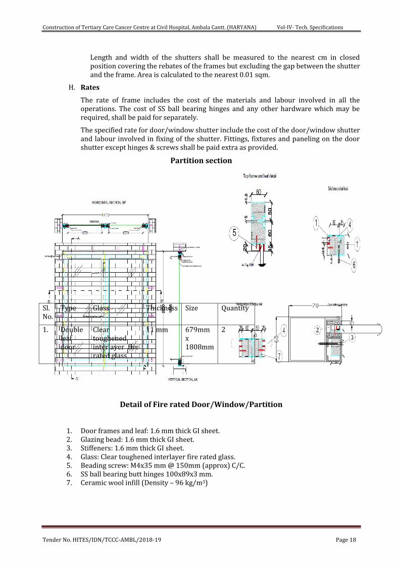
Partition section
Detail of Fire rated Door/Window/Partition
1. Door frames and leaf: 1.6 mm thick GI sheet. 2. Glazing bead: 1.6 mm thick GI sheet. 3. Stiffeners: 1.6 mm thick GI sheet. 4. Glass: Clear toughened interlayer fire rated glass. 5. Beading screw: M4x35 mm @ 150mm (approx) C/C. 6. SS ball bearing butt hinges 100x89x3 mm. 7. Ceramic wool infill (Density – 96 kg/m3)
Sl. No.
Type Glass Thickness Size Quantity
1. Double leaf door
Clear toughened interlayer fire rated glass
11 mm 679mm x 1808mm
2
Construction of Tertiary Care Cancer Centre at Civil Hospital, Ambala Cantt. (HARYANA) Vol-IV- Tech. Specifications
Tender No. HITES/IDN/TCCC-AMBL/2018-19 Page 19
10. FLOORING:
a. The flooring in the building shall be as per the approved floor finish drawings and laid in such a way that limits in floor levels would not exceed the limits provided in the latest CPWD specifications or manufactures specifications.
b. Wherever Vitrified Tile flooring is done, it shall be with multy grade/range 1st Quality tiles.
c. Slope in floors shall be provided as per architectural drawings, else the levels at any place when checked over a distance of one meters in any direction should not show variation in floor level more than 3 mm.
d. Rate for the items of flooring is inclusive of provision of sunken flooring and finishing edges of the same in bath kitchen, toilets, cutting holes for traps/ pipes etc., and nothing extra shall be paid on this account unless otherwise specified.
e. Protective layer to be provided of any type of flooring and nothing extra shall be paid on this account.
11. FALSE CEILING: -
a. False ceiling items in general are carried out as per the description of the item in the Bill of quantities and also as per the manufacturer’s specifications / as directed by the Engineer – in – Charge.
b. Location of particular type of false ceiling shall be as per relevant drawing, in its absence written approval of the Engineer – in - charge shall be obtained.
c. The false ceiling tiles from manufacturers using recycled materials shall be preferred.
12. MINERAL FIBRE CEILING TILE
a. 16 mm Mineral Fibre ceiling Tile
i. Material
Ceiling tiles shall be of made of mineral fibre of dimension 595x595mm with 16 mm thickness humidity resistance 99% Thermal conductivity K = 0.052-0.057 w/mK colour white, fire performance UK Class 0/Class 1 (BS 476 pt -6&7) suitable for green building application (GRIHA Criteria 17 & 29 SWAGRIHA 12) with recycled content not less than 30 % and light reflectance not less than 85%. NRC of 0.55 to 0.6. The tile and grid should carry a limited warranty of one year against sag.
ii. Frame
The frame work shall consist of G.I. ' T ' Sections for Main runners 15x38x3000mm length, Cross runners of 15x32x1200mm & 15x32x600mm size, 0.33 mm thickness as specified in the item with galvanization of 120 gsm (minimum) and perimeter wall angle of 0.40mm (minimum) thick gauge having equal flanges of size 24x24mm made from precoated G.I. Coil length of 3.0m fixed to the wall with the help of plastic rawl plugs at 450mm centre to centre with 50mm long dry wall SS screws. The frame work shall be executed in a manner so as to form a grid of 600x600mm as specified in the item.
iii. Fixing of Ceiling Tiles
The frame work shall be suspended from ceiling by L shape level adjuster hangers made of G.I. Of size 85x25x25x2mm having die cut slit for sliding into main T section, also having precut hole so that 6mm fully threaded MS rod length upto 1000mm goes through it and pierces into M6 dash fasteners (Galvanising of 80 gsm minimum) of 6
Construction of Tertiary Care Cancer Centre at Civil Hospital, Ambala Cantt. (HARYANA) Vol-IV- Tech. Specifications
Tender No. HITES/IDN/TCCC-AMBL/2018-19 Page 20
mm dia 50mm long, fixed to the slab and then tightened with check nuts, subsequently the bottom of 6 mm rod will be tightened with check nuts for adjusting the line & level. The tile shall be laid on 15x32mm wide T section flanges colour white having rotary stitching on all T sections i.e. the main runner, 1200 mm & 600 mm cross Tees with a web height of 32 mm and load carrying capacity of 7.57Kgs/m2.
iv. Measurements
Length and breadth of superficial area of the finished work shall be measured correct to a centimetre. Area shall be calculated in square meter correct to two places of decimal. No deduction will be made to openings of areas upto 40 square decimeter nor shall extra payment be made either for any extra material or labour involved in forming such openings. For openings exceeding 40 square decimetre in area, deduction in measurements shall be made but extra payment will be made for any extra material or labour involved in making such openings.
v. Rate
The rate shall include the cost of all the materials and labor involved in all the operation described above including scaffolding etc, if any required.
b. 20mm Mineral Fibre Ceiling Tile
General specification for providing and fixing mineral fibre false ceiling tiles item to be same as mentioned in para i. to v. of para a. above except the thickness of mineral fibre tile will be 20 mm and NRC value 0.7.
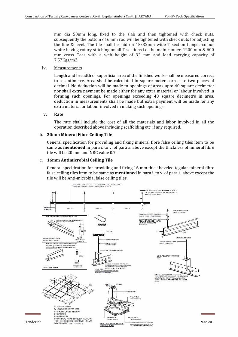
c. 16mm Antimicrobial Ceiling Tile
General specification for providing and fixing 16 mm thick beveled tegular mineral fibre false ceiling tiles item to be same as mentioned in para i. to v. of para a. above except the tile will be Anti-microbial false ceiling tiles.
Construction of Tertiary Care Cancer Centre at Civil Hospital, Ambala Cantt. (HARYANA) Vol-IV- Tech. Specifications
Tender No. HITES/IDN/TCCC-AMBL/2018-19 Page 21
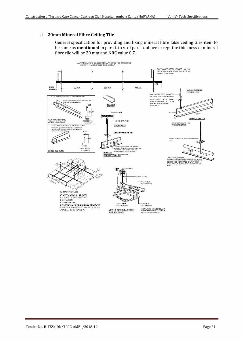
d. 20mm Mineral Fibre Ceiling Tile
General specification for providing and fixing mineral fibre false ceiling tiles item to be same as mentioned in para i. to v. of para a. above except the thickness of mineral fibre tile will be 20 mm and NRC value 0.7.
Construction of Tertiary Care Cancer Centre at Civil Hospital, Ambala Cantt. (HARYANA) Vol-IV- Tech. Specifications
Tender No. HITES/IDN/TCCC-AMBL/2018-19 Page 22
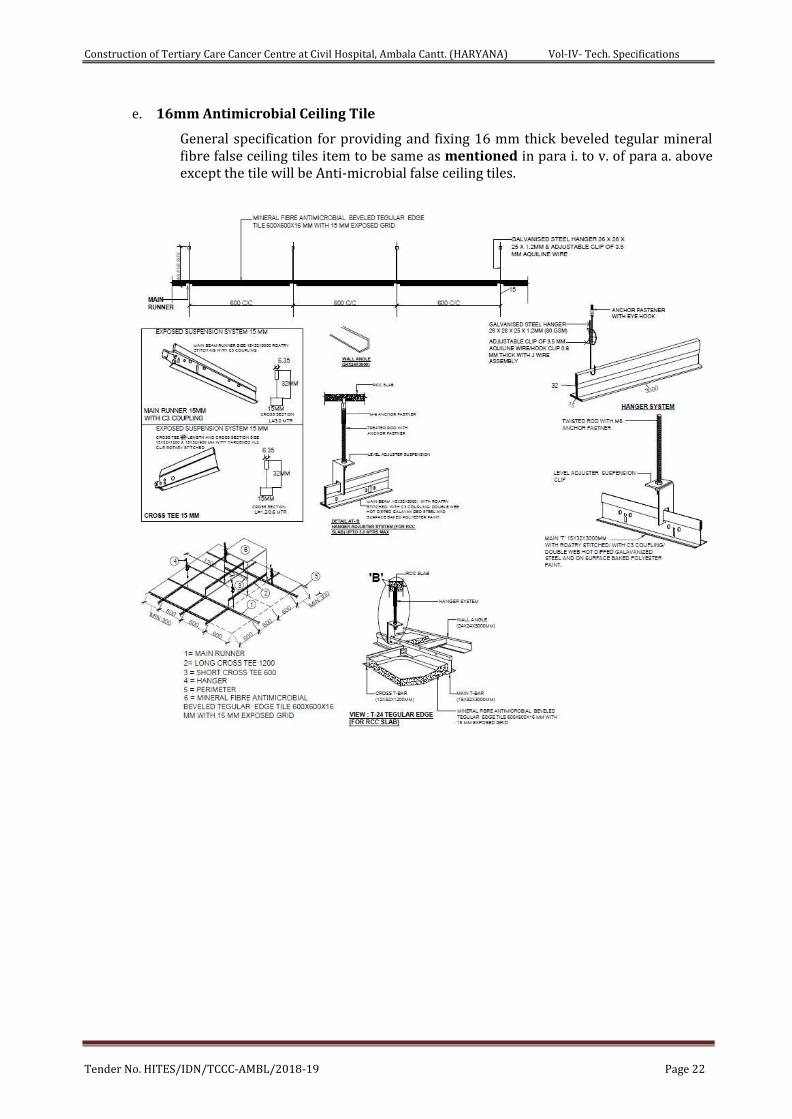
e. 16mm Antimicrobial Ceiling Tile
General specification for providing and fixing 16 mm thick beveled tegular mineral fibre false ceiling tiles item to be same as mentioned in para i. to v. of para a. above except the tile will be Anti-microbial false ceiling tiles.
Construction of Tertiary Care Cancer Centre at Civil Hospital, Ambala Cantt. (HARYANA) Vol-IV- Tech. Specifications
Tender No. HITES/IDN/TCCC-AMBL/2018-19 Page 23
13. LIGHT WEIGHT CALCIUM SILICATE FALSE CEILING TILES
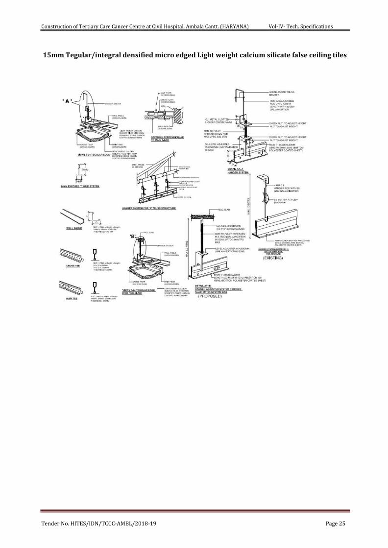
a. 15mm Tegular edged light weight calcium silicate false ceiling tiles
i. Material
15 mm thick tegular edged light weight calcium silicate false ceiling tiles with integral densified calcium silicate reinforced with fibre and natural filler false ceiling tiles of Size 595x595 mm of approved texture, design and patterns having NRC (Noise Reduction coefficient) of 0.50 (minimum) as per IS 8225:1987, Light reflectance of 85% (minimum). Non combustible as per BS: 476 (part-4), fire performance as per BS:476 (part 6 &7), humidity resistance of 100%, thermal conductivity <0.043 W/mK as per ASTM 518:1991.The tests shall have average density of 370 kg/m3 (minimum) as per ECBC code 2007. The tile shall be primer coated on both sides and the fair surface shall be having a factory finish in two coats of white dispersion type solvent free paint.
ii. Frame
The frame work shall consist of G.I. ' T ' Sections for Main runners 24x38x3000mm length, Cross runners of 24x32x1200mm & 24x32x600mm size, 0.33 mm thickness as specified in the item with galvanisation of 120 gsm (minimum) and perimeter wall angle of 0.40mm (minimum) thick gauge having equal flanges of size 24x24mm made from precoated G.I. Coil length of 3.0m fixed to the wall with the help of plastic rawl plugs at 450mm centre to centre with 40mm long dry wall SS screws. The frame work shall be executed in a manner so as to form a grid of 600x600mm as specified in the item.
iii. Fixing of Ceiling Tiles
The frame work shall be suspended from ceiling by L shape level adjuster hangers made of G.I. Of size 85x25x25x2mm having die cut slit for sliding into main T section, also having precut hole so that 6mm fully threaded MS rod length upto 1000mm goes through it and pierces into M6 dash fasteners (Galvanising of 80 gsm minimum) of 6 mm dia 50mm long, fixed to the slab and then tightened with check nuts, subsequently the bottom of 6 mm rod will be tightened with check nuts for adjusting the line & level. The tile shall be laid on 24x32mm wide T section flanges colour white having rotary stitching on all T sections i.e. the main runner, 1200 mm & 600 mm cross Tees with a web height of 32 mm and load carrying capacity of 7.57Kgs/m2.
iv. Measurements
Length and breadth of superficial area of the finished work shall be measured correct to a centimetre. Area shall be calculated in square meter correct to two places of decimal. No deduction will be made to openings of areas upto 40 square decimeter nor shall extra payment be made either for any extra material or labour involved in forming such openings. For openings exceeding 40 square decimetre in area, deduction in measurements shall be made but extra payment will be made for any extra material or labour involved in making such openings.
v. Rates
The rate shall include the cost of all the materials and labor involved in all the operation described above including scaffolding etc, if any required.
b. 15mm thick integral densified micro edged light weight calcium silicate false ceiling tiles
i. Material
Construction of Tertiary Care Cancer Centre at Civil Hospital, Ambala Cantt. (HARYANA) Vol-IV- Tech. Specifications
Tender No. HITES/IDN/TCCC-AMBL/2018-19 Page 24
15mm thick integral densified micro edged light weight calcium silicate false ceiling tiles with integral densified calcium silicate reinforced with fibre and natural filler false ceiling tiles of Size 595x595 mm of approved texture, design and patterns having NRC (Noise Reduction coefficient) of 0.50 (minimum) as per IS 8225:1987, Light reflectance of 85% (minimum). Non combustible as per BS: 476 (part-4), fire performance as per BS:476 (part 6 &7), humidity resistance of 100%, thermal conductivity <0.043 W/mK as per ASTM 518:1991.The tests shall have average density of 370 kg/m3 (minimum) as per ECBC code 2007. The tile shall be primer coated on both sides and the fair surface shall be having a factory finish in two coats of white dispersion type solvent free paint.
ii. Frame
The frame work shall consist of G.I. ' T ' Sections of 25 micron hot dipped galvanised iron section of 0.40mm thick on Silhouette profile, rotary stitched double webbed white with 6mm reveal profile (white/black) compromising of Main runners 15x42x3000mm length, Cross runners of 15x42x1200mm & 15x42x600mm size to form grid module of size 600x600mm. Galvanised iron perimeter wall angle of size 22x19x0.4mm of length 3000mm to be fixed on periphery wall/partition with the help of plastic rawl plugs at 450mm C/C and 40mm long dry wall SS screws. The work shall be carried out as per specifications, drawing and as per direction of Engineer-in-Charge.
iii. Fixing of Ceiling Tiles
The frame work shall be suspended from ceiling by L shape level adjuster hangers made of G.I. Of size 85x25x25x2mm having die cut slit for sliding into main T section, also having precut hole so that 6mm fully threaded MS rod length upto 1000mm goes through it and pierces into M6 dash fasteners (Galvanising of 80 gsm minimum) of 6 mm dia 50mm long, fixed to the slab and then tightened with check nuts, subsequently the bottom of 6 mm rod will be tightened with check nuts for adjusting the line & level. The tile shall be laid on 15x42mm wide T section flanges colour white having rotary stitching on all T sections i.e. the main runner, 1200mm & 600mm cross Tees with a web height of 42 mm and load carrying capacity of 7.57Kgs/m2.
iv. Measurements
Length and breadth of superficial area of the finished work shall be measured correct to a centimetre. Area shall be calculated in square meter correct to two places of decimal. No deduction will be made to openings of areas upto 40 square decimeter nor shall extra payment be made either for any extra material or labour involved in forming such openings. For openings exceeding 40 square decimetre in area, deduction in measurements shall be made but extra payment will be made for any extra material or labour involved in making such openings.
v. Rates
The rate shall include the cost of all the materials and labor involved in all the operation described above including scaffolding etc, if any required.
Construction of Tertiary Care Cancer Centre at Civil Hospital, Ambala Cantt. (HARYANA) Vol-IV- Tech. Specifications
Tender No. HITES/IDN/TCCC-AMBL/2018-19 Page 25
15mm Tegular/integral densified micro edged Light weight calcium silicate false ceiling tiles
Construction of Tertiary Care Cancer Centre at Civil Hospital, Ambala Cantt. (HARYANA) Vol-IV- Tech. Specifications
Tender No. HITES/IDN/TCCC-AMBL/2018-19 Page 26
14. POLYCARBONATE SHEET ROOFING
a. The polycarbonate sheet roofing shall be of Lexan of GE Plastics or equivalent approved make and shall conform to manufacture’s specifications. The contractor shall procure the sheets from the manufacturer as per the approved list. The material procured shall be free of any defects and damage to the edges, surface etc. The defective material shall be replaced by the contractor of his own cost. The contractor shall ensure that the material is procured and delivered at installation site without any damage.
b. Adequate care shall be taken for protection of the material before installation as well as afterwards till handing over the building for occupation. The contractor shall ensure careful handling and storage and prevent any rough handling, to prevent any edge or surface damage. Any panel with edge damaged or damage to the finish etc. shall not be allowed to be used in the work and shall be replaced by the contractor at his own cost. The contractor shall procure the material including providing for wastages, damages etc. in one lot so as not have any color and shade variation. Atleast one sample of the polycarbonate sheets brought by the contractor to the site of work shall be tested. The test shall be got done at reputed independent laboratory as approved by the Engineer-in-Charge. However, the contractor shall obtain and submit to the Department the manufacturer’s certificate for compliance of the polycarbonate sheets as per the manufacturer’s specifications and also copy of the manufacturer’s test report for the record.
c. The polycarbonate sheet shall be multi-wall (twin wall) section with thickness of the sheet not less than 16mm and the thickness of the walls on the two external faces not less than 0.8mm each. The sheet shall be extruded from polycarbonate material and shall have homogeneous composition of the material. The sheet shall have co-extruded UV protective layer. The sheet shall be fixed with the face treated for UV resistance, upward/exposed to sunlight. The weight of the sheets shall not be less than 1.7 Kg per sq.m. Light transmission shall be minimum 35% or as per manufacturers specifications. The sheets shall be obtained with closed edges. The sheet shall be bent (if required) to the require profile as per the architectural drawings but with radius not less than 175 times the thickness of the sheet. The sheet shall be fixed in a manner that the cells are parallel to the span of the shed.
d. The polycarbonate sheets shall be of colour and shade as approved by the Engineer-in-Charge.
e. The physical and the chemical characteristics of the polycarbonate sheets shall be as per the manufacturer’s specifications and shall conform to the ASTM standards. The sheets shall conform to BS 476 part 7 for the fire rating. The contractor shall submit written guarantee to the Engineer-in-Charge for the polycarbonate sheets procured and provided by him against any defects like peeling, breakage, fading of color/ discoloration, cracking, leakage through the roofing loss of strength etc. for a period of ten years after the date of completion of the work. The contractor shall obtain similar back-to-back guarantee from the manufacturer. The strength requirements are as specified below:
f. Distribution load: 800 N per sq.m.
g. The polycarbonate sheets shall be used in one piece along the span of the temporary sheds. The width of the sheet across the span of the shed shall not be more than 700 mm. The polycarbonate sheets shall be bent to required profile (linear or curvilinear) as per the architectural drawings and fixed in position, to the structural steel framework, using self-driving self-tapping screws with EPDM washers etc. The sheets shall be secured to the structural steel framework so as to withstand all the design dead, live, wind, other accidental loads etc. and shall be fixed in a workmanlike manner. It shall not have any sag. Therefore the fabrication work shall be got done through experienced & reputed fabricator, to be got approved from the Engineer-in-Charge. The contractor shall submit to the Engineer-in-Charge the shop drawings giving fixing details for the polycarbonate sheets in roofing and also quality assurance and methodology statement for the item. The polycarbonate sheets
Construction of Tertiary Care Cancer Centre at Civil Hospital, Ambala Cantt. (HARYANA) Vol-IV- Tech. Specifications
Tender No. HITES/IDN/TCCC-AMBL/2018-19 Page 27
shall be jointed along the length of the shed using aluminum top & bottom pressure plates having required profiles for fixing the EPDM gaskets, screws, washers etc. The aluminum pressure plates shall be color anodized or powder coated to the require shade. The joints in the sheet shall be provided only on the RHS steel sections of the framework and shall not be permitted elsewhere. The joint width of about 3-4 mm may be provided between the sheets at the junction for thermal expansion. The EPDM gaskets of the required profiles shall than be fixed in the grooves in the aluminum pressure plates on either side of the joint in the polycarbonate sheet. The bottom aluminum plate shall be fixed to the structural steel framework using self-driving self-tapping screws; washers etc. (one screw fixed to each sheet) and the screws fixed @300 mm center to center along the span of the shed.
h. The EPDM gaskets of the required profile shall be fixed in the grooves in the aluminum pressure plate on either side of the joint in the polycarbonate sheet. The top aluminum pressure plate shall than be fixed securely to the bottom aluminum plate using countersunk self-driving self-tapping screws, EPDM washers etc. All the screws shall be concealed using structural silicone sealant DC 995 of Dow Corning or equivalent approved brand. Also, wherever required (especially at the joint in the EPDM gasket etc.) the junction of the polycarbonate sheet and the sides of the pressure plates on both sides shall be sealed using structural silicone sealant DC 995 of Dow Corning or equivalent brand as approved. The item includes cost of all the operations and all inputs of the material [including Polycarbonate sheet, EPDM gaskets, anodized aluminum capping, anodized aluminum edge capping to the sheet with U-shaped EPDM gasket, all structure silicone sealant, self-driving self-tapping screws with EPDM washers, nuts, bolts, washers etc. and the like, labor, T & P, all the incidental charges, wastages etc. involved in the work. However for the purpose of payment only the actual area of the polycarbonate sheet provided and fixed in position shall be paid for separately under relevant item. The contractor shall maintain the roofing scratch and damage free till the handling over the building for occupation, at his own cost.]
i. Tolerance:-
i. Weight : 5% ii. Length : _-30 mm iii. Width : _ 0.5% iv. Thickness : _1mm
j. The polycarbonate sheets shall be obtained with protective films on both sides. Care shall be
taken while fixing to fix the sheets with UV protected side exposed to outside. The sheet shall be stored in a manner not to expose to direct sunlight. The sheet shall be cut to the required size or drilled using the toothed blade/machine. After fixing the protective film shall be removed and the sheets cleaned using non-alkaline based detergent and abrasive equipments or solvents be avoided. The silicones, gaskets, tapes etc. shall be compatible with the polycarbonate sheet.
k. For joining the sheets, at least one complete channel width of each sheet shall be secured per sheet within the joining profile. Since thermal coefficient of expansion of the sheets is different from the RHS steel frames, suitable provision shall be made for accommodating differential expansions. Also any rigid jointing agent that may prevent thermal movements shall not be used. The required section aluminum profiles (upper central profile, lower central profile and top profile) for fixing the polycarbonate sheet to the structural framework as well as for joining the sheet shall be as per the manufacturer’s specifications .The top capping profile shall be snap fit to the upper central profile, The EPDM gaskets and the screws shall be provided as per the manufacturer’s specifications.
l. The Gaskets shall be extruded micro wave/ steam cured EPDM/ silicone of approved quality compatible with substrates, finishes and other components they are in contact with. All gaskets exposed directly on the exterior face shall be silicon gaskets, which are UV resistant. They shall not degenerate/discolor or/each on exposure to weather/ rain/pollutants etc.
Construction of Tertiary Care Cancer Centre at Civil Hospital, Ambala Cantt. (HARYANA) Vol-IV- Tech. Specifications
Tender No. HITES/IDN/TCCC-AMBL/2018-19 Page 28
15. UNDER DECK Insulation- Glass Wool Insulation Board
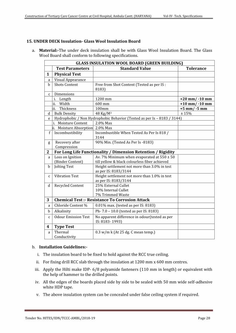
a. Material:-The under deck insulation shall be with Glass Wool Insulation Board. The Glass Wool Board shall conform to following specifications.
GLASS INSULATION WOOL BOARD (GREEN BUILDING) Test Parameters Standard Value Tolerance 1 Physical Test a Visual Appearance b Shots Content Free from Shot Content (Tested as per IS :
8183)
c Dimensions i. Length 1200 mm +20 mm/ -10 mm ii. Width 600 mm +10 mm/ -10 mm iii. Thickness 100mm +5 mm/ -5 mm
d Bulk Density 48 Kg/M3 ± 15% e Hydrophobic / Non Hydrophobic Behavior (Tested as per Is – 8183 / 3144)
i. Moisture Content 2.0% Max ii. Moisture Absorption 2.0% Max
f Incombustibility Incombustible When Tested As Per Is 818 / 3144
g Recovery after Compression
90% Min. (Tested As Per Is -8183)
2 For Long Life Functionality / Dimension Retention / Rigidity a Loss on Ignition
(Binder Content) Av. 7% Minimum when evaporated at 550 ± 50 till yellow & black colourless fiber achieved
b Jolting Test Height settlement not more than 3.0% in test as per IS: 8183/3144
c Vibration Test Height settlement not more than 1.0% in test as per IS: 8183/3144
d Recycled Content 25% External Cullet 10% Internal Cullet 7% Trimmed Waste
3 Chemical Test :- Resistance To Corrosion Attack a Chloride Content % 0.01% max. (tested as per IS: 8183) b Alkalinity Ph- 7.0 – 10.0 (tested as per IS: 8183) c Odour Emission Test No apparent difference in odour(tested as per
IS: 8183- 1993)
4 Type Test a Thermal
Conductivity 0.3 w/m k (At 25 dg. C mean temp.)
b. Installation Guidelines:-
i. The insulation board to be fixed to hold against the RCC true ceiling.
ii. For fixing drill RCC slab through the insulation at 1200 mm x 600 mm centres.
iii. Apply the Hilti make IDP- 6/8 polyamide fasteners (110 mm in length) or equivalent with the help of hammer to the drilled points.
iv. All the edges of the boards placed side by side to be sealed with 50 mm wide self-adhesive white HDP tape.
v. The above insulation system can be concealed under false ceiling system if required.
Construction of Tertiary Care Cancer Centre at Civil Hospital, Ambala Cantt. (HARYANA) Vol-IV- Tech. Specifications
Tender No. HITES/IDN/TCCC-AMBL/2018-19 Page 29
16. UNDER DECK INSULATION SYSTEM-Polystyrene Rigid Insulation Board
A. Materials
50mm thick extruded polystyrene rigid insulation board of required size for Underdeck Insulation System, complying with ISO 4898:2008 & ASTM C 578-08b-type VI, having thermal conductivity of 0.0289 W/mk as per ASTM C 578 (Measured as per IS 3346), Compressive strength of 350 KPA listed as per ASTM D 1621, density of 34-36 kg/Cum as per ASTM D 1622, Water absorption < 1% by Volume as per ASTM D 2842, Oxygen Index of 24.1 to 28.1 listed as per ASTM D 2863, cell size 0.4mm of dia (max) as per ASTM D 3576. Fire retardant property as per DIN , Part 1 of Class B2 and as per ASTM E 84 Class A.
B. Installation Process
i. The specified Under Deck Insulation System shall be applied by an Authorized applicator only.
ii. The level of the slab should be checked and kept within permissible limit of variation of 3 to 5mm.
iii. The Substrate/ Roof Underdeck on which the insulation system needs to be installed must be free from all waste products such as petroleum, grease, oil, solvents, vegetable or mineral oil, animal fat etc.
iv. The Insulation board must be fixed to the concrete slab from inside with the help of water based adhesive and Fasteners with PVC Capping. This has to be ensured that the PVC screws are embedded in the concrete with a minimum distance of 50mm from the edges and have a pull out strength of 0.3 kN.
C. Requirement for extruded polystyrene rigid insulation board
Since this product is a performance based product, the third Party testing is Mandatory and should be done from any NABL approved laboratory or any other accreditation body which operates in accordance with test ISO/IEC 17011 and accredits labs as per ISO/IEC-17025 for testing.
Sr. No. Requirement Test Standard Remarks
1 Thermal Conductivity Having 180 days aged thermal conductivity of 0.0289 W/mk. ASTM C 578 Mandatory
2 Compressive strength of > 350 KPA. ASTM D 1621 Mandatory 3 Density of 34-36 kg/Cum. ASTM D 1622 Mandatory 4 Water absorption < 1% by Volume. ASTM D 2842 Mandatory 5 Oxygen Index of 24.1 to 28.1 ASTM D 2863 Mandatory 6 Cell size 0.4mm of dia (max). ASTM D 3576 Mandatory
7 Fire retardant property as per DIN , Part 1 of Class B2 ------ Mandatory
8 Fire retardant property ASTM E 84 CLASS A Mandatory
D. Measurements
Length and breadth of the roofing insulation shall be measured correct to a cm and the surface area worked out in square metre of the finished work.
No deduction shall be made for openings of areas upto 40 square decimetre. No extra payment will be made for any extra material or labour involved in forming such openings. For openings exceeding 40 square decimetre in area, deduction for the full opening will be made, but no extra will be paid for any extra material or labour involved in forming such openings.
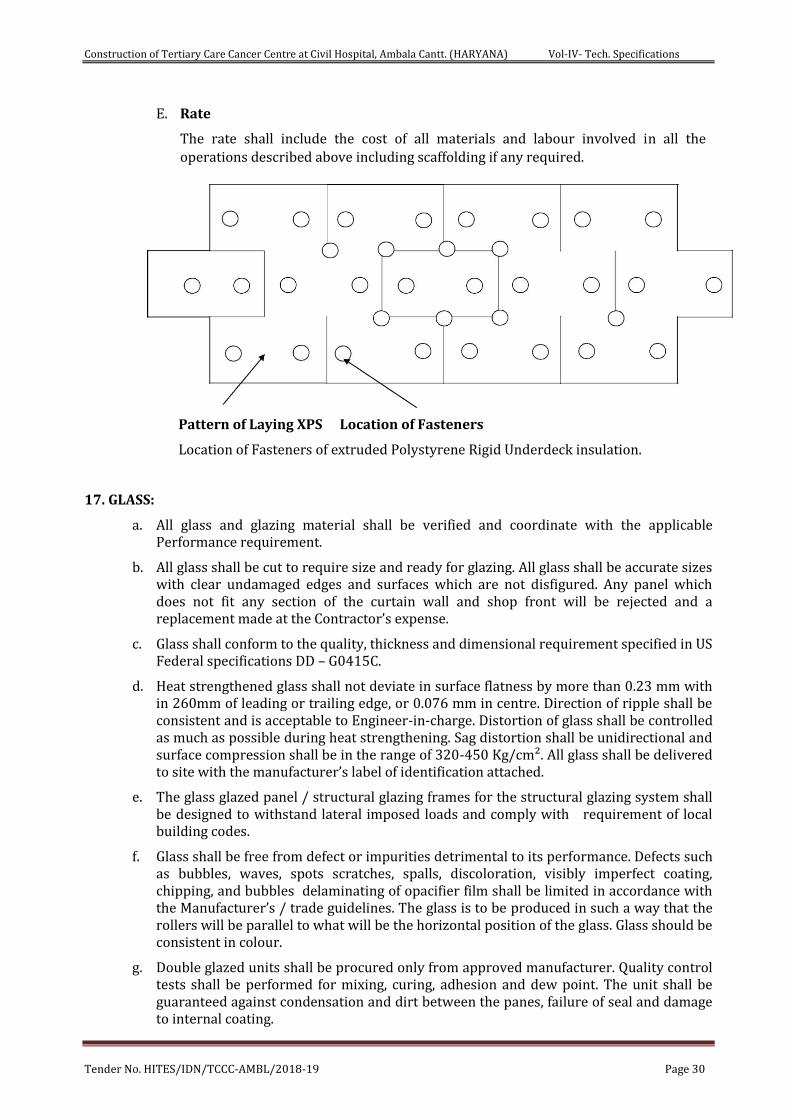
Construction of Tertiary Care Cancer Centre at Civil Hospital, Ambala Cantt. (HARYANA) Vol-IV- Tech. Specifications
Tender No. HITES/IDN/TCCC-AMBL/2018-19 Page 30
E. Rate
The rate shall include the cost of all materials and labour involved in all the operations described above including scaffolding if any required.
Pattern of Laying XPS Location of Fasteners
Location of Fasteners of extruded Polystyrene Rigid Underdeck insulation.
17. GLASS:
a. All glass and glazing material shall be verified and coordinate with the applicable Performance requirement.
b. All glass shall be cut to require size and ready for glazing. All glass shall be accurate sizes with clear undamaged edges and surfaces which are not disfigured. Any panel which does not fit any section of the curtain wall and shop front will be rejected and a replacement made at the Contractor’s expense.
c. Glass shall conform to the quality, thickness and dimensional requirement specified in US Federal specifications DD – G0415C.
d. Heat strengthened glass shall not deviate in surface flatness by more than 0.23 mm with in 260mm of leading or trailing edge, or 0.076 mm in centre. Direction of ripple shall be consistent and is acceptable to Engineer-in-charge. Distortion of glass shall be controlled as much as possible during heat strengthening. Sag distortion shall be unidirectional and surface compression shall be in the range of 320-450 Kg/cm². All glass shall be delivered to site with the manufacturer’s label of identification attached.
e. The glass glazed panel / structural glazing frames for the structural glazing system shall be designed to withstand lateral imposed loads and comply with requirement of local building codes.
f. Glass shall be free from defect or impurities detrimental to its performance. Defects such as bubbles, waves, spots scratches, spalls, discoloration, visibly imperfect coating, chipping, and bubbles delaminating of opacifier film shall be limited in accordance with the Manufacturer’s / trade guidelines. The glass is to be produced in such a way that the rollers will be parallel to what will be the horizontal position of the glass. Glass should be consistent in colour.
g. Double glazed units shall be procured only from approved manufacturer. Quality control tests shall be performed for mixing, curing, adhesion and dew point. The unit shall be guaranteed against condensation and dirt between the panes, failure of seal and damage to internal coating.
Construction of Tertiary Care Cancer Centre at Civil Hospital, Ambala Cantt. (HARYANA) Vol-IV- Tech. Specifications
Tender No. HITES/IDN/TCCC-AMBL/2018-19 Page 31
h. All glass breakage caused by the Contractor or his sub-contractor because of negligence or caused by the installation of faulty work by him shall be replaced by the Contractor at his own expense without delay to the project completion.
18. GLASS ENTRANCES AND GLAZING WITH PATCH FITTING
A. GENERAL
i. The contractor shall be responsible for design, fabrication, supply, installation, test and guarantee of all items including taking all measures that may be required to complete the work as per Architectural concept drawings and specifications details.
ii. The specialist agency engaged to carry out the external glazing installation and supply shall have at least 5 years of relevant experience and have completed external glazing systems of similar nature and equivalent scale of works as shown in the tender documents.
iii. The specialist contractor shall submit an outline of recent comparable works (illustrated by appropriate drawings, sketches, photographs, brochures) by the firm / its technical partner to illustrate the competence, experience and suitability of the firm.
B. The scope of work shall include:
i. Design, preparation of shop drawings, calculations, engineering data and test reports.
ii. Fabrication and installation of Glass Entrances and Glazing with Patch Fittings system.
iii. All anchors, fixings, attachments, reinforcements, steel reinforcing for mullions and transoms required for a complete installation, except those specifically indicated as being provided by other trades.
iv. Exposed Architectural mullions and other support members.
v. Finishes, protection coatings and treatments.
vi. Sealing with approved sealants within and around the perimeter.
vii. All thermal insulation, firesafing etc. including supports and/or backing.
viii. All caulking, sealing, electrometric and metal flashing, and gaskets including sealing at junctions with roof, ground-floor waterproofing and building expansion joints between structures.
ix. Electrical bonding and ear thing of all metal cladding elements.
x. Provisions to receive electrical outlets and cutouts for conduits and other electrical work.
xi. Glass and glazing.
xii. Transportation, storage, handling, protection and cleaning.
C. SUBMITTALS
i. Product Data: Include construction details, material descriptions, dimensions of individual components, profiles and finishes.
ii. Shop Drawings
D. Fabrication and installation details, including followings
i. Plans, elevations and sections.
ii. Details of fittings and glazing.
iii. Hardware quantities, locations and installation requirements.
Construction of Tertiary Care Cancer Centre at Civil Hospital, Ambala Cantt. (HARYANA) Vol-IV- Tech. Specifications
Tender No. HITES/IDN/TCCC-AMBL/2018-19 Page 32
iv. Sample for verification, for each type of exposed finish required for
1. Metal finish: 150mm long section of patch fittings, rails and other items.
2. Glass: 150mm square, showing exposed edge finish.
E. MATERIALS
i. Glass
1. Glass shall be as specified in drawing or BOQ or as per design requirement. It shall be Indian / imported hard coated reflective bronze and heat strengthened glass. It shall be of approved make.
2. In toughening of Glass, rolling direction shall be parallel to the width of the glass panel such that waviness if any is parallel to the horizontal and no waviness parallel to the vertical and to ensure that such waviness is of negligible order.
ii. Components
1. Patch fittings: Stainless steel clad aluminium
2. Floating Transom Bar: Steel cladded in metal matching fittings and in sizes recommended by manufacturer for application indicated. Include stainless steel support rods, lateral adjustment and ceiling channel. Support fins to be metal, finished to match transom bar.
3. Rails: Stainless steel clad aluminium.
4. Accessory Fittings : Matching with patch fittings and rails metal and finish for overhead door stop, Centre hosing lock, glass support fin brackets and other as shown in drawing.
5. Anchors and fastenings: Concealed
6. Weather stripping: Sweep type
iii. Hardware
1. Hardware should be heavy duty in matching finish
2. Concealed Floor Closer and Top Pivots
a. Centre hung; BHMA A156.4, Grade 1; including cases, bottom arm, top walking beam pivots, plates, and accessories required for complete installation.
b. Swing : Double acting; Positive dead stop, concealed with hold open angle
c. Delayed action closing
d. Concealed Overhead Holder: Grade 1, with dead stop setting coordinated with concealed floor closer.
e. Push-pull set : Stainless steel finish
3. Lock set of approved make.
F. FABRICATION
1. Provide holes and cutouts in glass to receive hardware, fittings, rails and accessories before tampering glass. Fully temper glass using horizontal (roller-hearth) process and fabricate so, when installed, roll wave distortion is parallel with bottom edge of door or tile.
2. Factory assembled components and factory installed hardware to greatest extent possible.
Construction of Tertiary Care Cancer Centre at Civil Hospital, Ambala Cantt. (HARYANA) Vol-IV- Tech. Specifications
Tender No. HITES/IDN/TCCC-AMBL/2018-19 Page 33
G. EXECUTION
1. Examine areas and condition for compliance with requirements for installation tolerances and other conditions affecting performance of work.
2. Install all glass system and associated components according to manufacturer’s written instructions.
3. Set units in level and plumb.
4. Maintain uniform clearances between adjacent components.
5. Lubricate hardware and other moving parts according to manufacturer’s written instructions.
6. Set, seal and grout floor closer cases as required suiting hardware and substrate indicated.
H. CLEANING
1. The Contractor shall ensure that all actions are taken during installation to eliminate the effects of corrosive substances on the finishes.
2. The Contractor shall clean both internal and external surfaces to remove corrosive substances, dust or cement / mortar dropping during the installation as may be directed and instructed by the Engineer – in - charge.
3. The internal surfaces of glass and aluminum frame are to be cleaned with compatible cleaning agents prior to the installation of the internal protective sheeting.
4. The Contractor shall provide written verification that cleaning agents are compatible with aluminum, stainless steel, glass coatings, granite, glazing materials and sealants. In no case shall alkaline or abrasive agent be used to clean the surface. Care shall be taken during cleaning to avoid scratching of the surface by grit particles.
5. Prior to snagging inspections the Contractor shall, remove the internal protection sheets and carry out a thorough cleaning of all glass and aluminum.
6. The Contractor shall also make good any physical damage to the structure including scratches, dents, abrasions, pitting, etc. to the satisfaction of the Engineer – in - charge.
7. Manufacturer's delivery or job markings on glass and adhesive for manufacturer's labels shall be either a neutral or slightly acidic material. In no case shall such material be alkaline; any staining of glass by alkaline material will be cause for rejection of the glass.
8. After the installation of each pane of glass all markings and labels shall be carefully and completely removed from the panes. Thereafter no markings or labels of any sort shall be placed on the glass.
9. Glazed openings shall be identified by suitable warning tapes or flags attached with a non-staining adhesive or other suitable means to the framing of the opening. Tapes or flags shall not be in contact with glass.
10. As soon as it is practically possible after the issuance of the occupation Permit for the Building, the Contractor is to carry out a complete cleaning of the external face.
I. PERFORMANCE GUARANTEE: The contractor shall offer a minimum of 10 year Performance Warranty for the entire installation carried out.
J. MEASUREMENTS: - Measurements shall be in Sq m of actual area covered.
K. RATE: - Rate shall include all required labour, material, designing, drawing conveyance, testing at approved laboratory breakage, wastage, supervision, protection till handing over etc. complete.
Construction of Tertiary Care Cancer Centre at Civil Hospital, Ambala Cantt. (HARYANA) Vol-IV- Tech. Specifications
Tender No. HITES/IDN/TCCC-AMBL/2018-19 Page 34
19. ALUMINIUM COMPOSITE PANELS (ACP) CLADDING
a. Scope of Work includes providing and fixing Aluminium Composite panel cladding including framing as per the elevation, section and the plan drawings provided, fabricated out of heavy duty Aluminium extruded profiles conforming to alloy 643900 WP with chemical composition and mechanical properties as per IS-733 and as per specifications. The scope of work shall be read in conjunction with the specification of curtain walling / structural Glazing System.
b. The contractor shall design, supply, fabricate, deliver and install and guarantee all construction necessary to provide a complete aluminium composite panel cladding, complete with all necessary anchors, hardware and fittings to provide a total installation, fully in conformity with the requirements and intent of the drawing and specification as per item description.
c. The contractor shall design the cladding as per the prevalent site conditions and building elevations profiles. The design parameters shall be in conformity the structural glazing system. No extra claims shall be entertained at any stage for aluminum profile/ wall thickness and size dimensions. The Contractor must quote rates accordingly.
d. The anchoring / bracing of the wall cladding to the RCC beams/ columns shall be done with non-corrosive galvanized brackets of approved design, (Galvanizing to be done conforming to IS 4759-1996 up to 610 gms. Per Sq. M. (80- 90 micron thickness).
e. The framework shall be aligned for the entire height of each Mullion and of the entire width of each Transform by laser beam equipment to ensure 100 percent ‘X’ axis and ‘Y’ axis alignment.
f. The system should also provide for pressure equalization. The details for pressure equalization to be submitted by the contractor and got approved by the Engineer-in-charge.
g. EPDM Gaskets of suitable profiles (to accommodate shall be provided including the labour element for fixing in appropriate locations is to be included in the rate).
h. The Periphery of the framework shall be sealed both from inside and outside with silicon weather sealant to make the cladding watertight.
i. Cost of Aluminium composite panel consisting of a core of polyethylene sandwiched between two aluminium skins of 0.5mm thickness with a mild edge. 4 mm total thickness with surface finish of PVDF coating as approved by the Engineer-in-charge, as shown in the elevation, plan and cross section drawings along with labour element for cutting stacking, carrying to heights and fixing to appropriate locations is included in the rates.
j. All the vertical and horizontal section grooves are to be sealed non staining silicon sealant of make as specified in the list of approved make to make the entire system synchronies with the basic structural glazing/curtain wall structure and also make the system air tight and watertight. The fixing details should be got approved by the Engineer-in-charge. The peel off foil should be removed at the time of handing over as may be required by the Engineer-in-charge.
k. Any joint provided between cladding elements to cater for individual panel installation and shall be sealed off with extruded EPDM gasket or silicon sealant.
l. Product
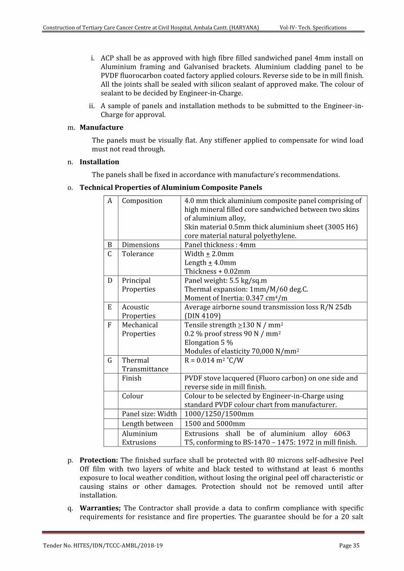
Construction of Tertiary Care Cancer Centre at Civil Hospital, Ambala Cantt. (HARYANA) Vol-IV- Tech. Specifications
Tender No. HITES/IDN/TCCC-AMBL/2018-19 Page 35
i. ACP shall be as approved with high fibre filled sandwiched panel 4mm install on Aluminium framing and Galvanised brackets. Aluminium cladding panel to be PVDF fluorocarbon coated factory applied colours. Reverse side to be in mill finish. All the joints shall be sealed with silicon sealant of approved make. The colour of sealant to be decided by Engineer-in-Charge.
ii. A sample of panels and installation methods to be submitted to the Engineer-in-Charge for approval.
m. Manufacture
The panels must be visually flat. Any stiffener applied to compensate for wind load must not read through.
n. Installation
The panels shall be fixed in accordance with manufacture’s recommendations.
o. Technical Properties of Aluminium Composite Panels
A Composition 4.0 mm thick aluminium composite panel comprising of high mineral filled core sandwiched between two skins of aluminium alloy, Skin material 0.5mm thick aluminium sheet (3005 H6) core material natural polyethylene.
B Dimensions Panel thickness : 4mm C Tolerance Width + 2.0mm
Length + 4.0mm Thickness + 0.02mm
D Principal Properties
Panel weight: 5.5 kg/sq.m Thermal expansion: 1mm/M/60 deg.C. Moment of Inertia: 0.347 cm4/m
E Acoustic Properties
Average airborne sound transmission loss R/N 25db (DIN 4109)
F Mechanical Properties
Tensile strength >130 N / mm2 0.2 % proof stress 90 N / mm2
Elongation 5 % Modules of elasticity 70,000 N/mm2
G Thermal Transmittance
R = 0.014 m2 ˚C/W
Finish PVDF stove lacquered (Fluoro carbon) on one side and reverse side in mill finish.
Colour Colour to be selected by Engineer-in-Charge using standard PVDF colour chart from manufacturer.
Panel size: Width 1000/1250/1500mm
Length between 1500 and 5000mm
Aluminium Extrusions
Extrusions shall be of aluminium alloy 6063 T5, conforming to BS-1470 – 1475: 1972 in mill finish.
p. Protection: The finished surface shall be protected with 80 microns self-adhesive Peel
Off film with two layers of white and black tested to withstand at least 6 months exposure to local weather condition, without losing the original peel off characteristic or causing stains or other damages. Protection should not be removed until after installation.
q. Warranties; The Contractor shall provide a data to confirm compliance with specific requirements for resistance and fire properties. The guarantee should be for a 20 salt
Construction of Tertiary Care Cancer Centre at Civil Hospital, Ambala Cantt. (HARYANA) Vol-IV- Tech. Specifications
Tender No. HITES/IDN/TCCC-AMBL/2018-19 Page 36
spray resistance and fire properties. The guarantee should be for a 20 year period against peeling chalking (No. 8 rating), fading, blistering, flaking, chipping and cracking.
r. Measurement: The measurement shall be for exposed actual surface area with grooves cladded on plain/ curved surface excluding the concealed trims.
s. Technical Data: - The technical data provided hereunder is for guidelines. The data, specific for the site location, shall be got approved by the contractor from the Engineer-in-Charge for the design of the ACP and structural Glazing System.
i. Design Wind Loading
850 N/m2 positive and negative to Podium.
1150 N/m2 positive and negative to Tower.
1500 N/m2 positive and negative to Crown to Tower.
No cladding element shall sustain permanent deformation of failure under loading equivalent 1.5 times the design wind pressure specified.
ii. Deflection
Deflection of any aluminium frame shall not exceed 1/175 of the clear span.
iii. Expansion and Contraction
The cladding shall be so fabricated and erected as to provide for all expansion and contraction of the components. Any temperature change due to climatic conditions shall not cause harmful buckling, opening of joints, undue stress on fastening and anchors, noise of any kind or other defects.
iv. Flatness
The cladding surface taken individually shall not have any irregularities such as oil canning, waves, buckles and other imperfections when viewed at any position but not less than at an angle of 15 degrees to the true plane of the panel with natural lighting of incident of not less than the same angle.
v. Water Tightness
The panel cladding shall be so constructed to be water tight with provision for rear ventilation.
vi. Acoustic Treatment
The cladding panel system shall be designed so as to dampen noise caused by splashing water.
B. Fixings
i. Fasteners including concealed screws, nuts, bolts and other items required for connecting aluminium to aluminium shall be of non-magnetic stainless steel.
ii. Rivets used for fastening panel to aluminium sub-frame shall be of alloy aluminium large flange head type with stainless steel mandrel.
iii. All fixing anchors, brackets and similar attachments used in the erection shall be of aluminium or non-magnetic stainless steel.
C. Weather seal
i. All exposed joints between panels which are required to be water tight, shall be sealed with extruded EPDM gasket of hardness approx. 75 SHORE.
ii. All secondary weather seal shall be of self-adhesive tape as approved by the Engineer-in-charge.
Construction of Tertiary Care Cancer Centre at Civil Hospital, Ambala Cantt. (HARYANA) Vol-IV- Tech. Specifications
Tender No. HITES/IDN/TCCC-AMBL/2018-19 Page 37
20. STUCTURAL GLAZING SYSTEM
A. Scope of Work
i. The contractor shall design, engineer, test, fabricate, deliver, install, and guarantee all construction necessary to provide a complete structural glazing system to the proposed building, all in conformity with the Drawings as shown. Specification and all relevant construction regulations including providing any measures that may be required to that end, notwithstanding any omissions or inadequacies of the Drawings and/or without limiting the generalities of the foregoing, the structural glazing Systems shall include, without being limited to, the followings:
Metal frames, glass glazing, spandrels, ventilators, finish hardware, copings metal closure, windows etc.
All anchors, attachments, reinforcement and steel reinforcing for the systems required for the complete installations.
All thermal insulation associated with the system. All fire protection associated with the system.
All copings, end closure and metal cladding to complete the system.
All sealing and flushing including sealing at junctions with other trades to achieve complete water tightness in the system.
Isolation of dissimilar metals and moving parts.
Anticorrosive treatment on all metals used in the system. Polyester powder coating aluminium sections.
ii. The contractor shall also be responsible for providing the followings:
Engineering Proposals, Shop Drawings, Engineering data and Structural Calculations in connection with the design of the structural glazing System.
Scheduling and Monitoring of the Work.
Mock-ups, samples and test units.
Performance testing of the structural glazing framing and glazing assembly.
Co-ordination with work of other trades.
Protection.
All final exterior and interior cleaning and finishing of the structural glazing System
As-built record drawings and photographs.
Guarantees and Warranties.
All hoisting, staging and temporary services.
Conceptualising and design of a suitable maintenance system for structural glazing.
iii. The water tightness and structural stability of the whole structural glazing System are the prime responsibility of the Contractor. Any defect or leakage found within the Guarantee Period shall be sealed and made good all at the expense of the Contractor.
iv. The structural glazing system shall be designed to provide for expansion and
Construction of Tertiary Care Cancer Centre at Civil Hospital, Ambala Cantt. (HARYANA) Vol-IV- Tech. Specifications
Tender No. HITES/IDN/TCCC-AMBL/2018-19 Page 38
contraction of components which will be caused by an ambient temperature range without causing buckling, stress on glass, failure of joint sealants, undue stress on structural elements or other detrimental effects. Specific details should be designed to accommodate thermal and building movements.
B. Building Regulations
Structural glazing shall comply with all Government Codes and Regulations including IS codes, if any.
All structural glazing, individual aluminium and glass components and all completed work shall be designed and erected to comply with the following:
i. Design load and deflection.
ii. Structural glazing construction in its entirety shall be fabricated and erected to withstand without damage or permanent deformation inward (positive) and outwards (negative) pressure, all acting normal to the construction plane with a maximum deflection of not exceeding 1/175 of the clear span between structural support or 20mm maximum whichever is less.
iii. Structural performance of all parts of structural glazing system shall conform to relevant IS codes, wind load as per IS-875 and seismic loads as per IS-1893. Deflection shall cause no permanent set in excess of 1/1000 of span nor evidence of structure failure.
iv. Design Wind Loading
850 N/m2 positive and negative to Podium.
1150 N/m2 positive and negative to Tower.
1500 N/m2 positive and negative to Crown to Tower.
No cladding element shall sustain permanent deformation of failure under loading equivalent 1.5 times the design wind pressure specified.
C. Measurements
Measurements of the structural glazing shall be in the metric system in sq.m correct to two places of decimal. The area considered for measurement shall be net area as fixed on the exterior face of the structural glazing including open able windows as part of structural glazing. The contractor shall be responsible for verifying all the dimensions and actual conditions on site.
D. Rate
The rates shall include the cost of all the operations described above including the cost of all materials, labour, design, fabrication, erection, finishing, scaffolding and testing of water tightness etc.
E. Tender Drawings and Specifications
The tender drawings indicate profile and configuration required together with relationship to structural frame and interior building elements.
The Specification and tender drawings is of the performance type and includes only the minimum requirements of the /structural glazing Wall System without limiting the Contractor to the method of achieving desired performance.
F. POST TENDER REQUIREMENTS
i. Design Proposals
The contractor shall propose the final design in such a way that all basic
Construction of Tertiary Care Cancer Centre at Civil Hospital, Ambala Cantt. (HARYANA) Vol-IV- Tech. Specifications
Tender No. HITES/IDN/TCCC-AMBL/2018-19 Page 39
functional and architectural requirements are fulfilled and get the same approved by Deptt. However, basic design requirements as described in the specification and other Architectural requirements such as the size of window, net glass area, ventilator, configuration of windows and spandrels shall be retained.
The design proposals shall be in the form of drawings, drawn to full scale as far as practical and specification shown in or describing all items of work including:
Request details as indicated on the tender drawings.
Metal quality, finishes and thickness.
Glass quality, coating and thickness and proposed manufacturer’s brand names.
Sections of the mullion and transom together with structural calculations.
Arrangement and jointing of components.
Field connections especially mullion to mullion and transom to mullion.
Fixing and anchorage system of typical wall unit together with structural calculations.
Drainage system and provision in respect of water leakage in the curtain wall/structural glazing system.
Provisions for thermal movements.
Sealant and sealing method.
Glazing method.
Wind load and seismic load and any other specific load considered in the design.
Lightning protection link-up system of the curtain wall/structural glazing for connection and incorporation into the lightning conductor system of the building. Design concept must be stated in the proposal.
The maximum permissible structural tolerances of the building that the system has been designed to accommodate in case this tolerance exceed those specified in the Specification.
Any parts of the curtain wall/structural glazing, when completed, shall be within the following tolerances:
Deviation from plumb, level or dimensioned angle must not exceed 3mm per 3.5m of length of any member, or 6mm in any total run in any line.
Deviation from theoretical position on plan or elevation, including deviation from plumb, level or dimensioned angle, must not exceed 9mm total at any location.
Change in deviation must not exceed 3mm for any 3.5m run in any direction.
ii. Samples
The contractor shall also submit samples of mullion and transom sections in lengths of 300mm with the same finish and workmanship along with the proposals and 300mmx300mm samples of glass (samples to include exposed screws and other exposed securing devices, if any).
iii. Preliminary Programme
The tenderer shall also submit a preliminary programme of the contract works showing the various stages of design sampling, testing, fabrication, delivery and
Construction of Tertiary Care Cancer Centre at Civil Hospital, Ambala Cantt. (HARYANA) Vol-IV- Tech. Specifications
Tender No. HITES/IDN/TCCC-AMBL/2018-19 Page 40
installation of the works.
iv. Upon approval of the shop drawings, at least 4 copies shall be submitted by the Contractor.
v. The Contractor/Sub-contractor shall submit a maintenance manual for the curtain wall/structural glazing system inclusive of all metal parts, glass and finish etc.
vi. During detailed design and execution any details may increase as per actual requirement at site, these variations shall be executed without any extra cost implications to the HITES.
G. Execution- Performance Testing
The performance tests are to be conducted on the structural glazing system, if the area of the structural glazing system exceeds 2500 Sq.ms from the certified laboratories accredited by NABL (National Accreditation Board for Testing and Calibration Laboratories), Department of Science and Technology, India. The decision of the Engineer-in-charge about the necessity of testing of shall be final and binding.
i. General Requirements
Mock-up units shall be constructed by the contractor and tested to determine the structural stability as well as air and water infiltration or leakage at glazing beads and all other joints designed into the façade.
After approval of structural calculations and shop drawings for the structural glazing, one (1) Test Unit for performance testing of the structural glazing shall be constructed by the contractor at a laboratory approved by the Department (Refer BOQ).
Erect mock-up under manufacturer’s/installer’s direct supervision and employ workmen as they would be employed during the actual erection at the job site.
Test procedures test schedules and test locations shall be submitted to Engineer-in-charge for approval before testing.
Prior to fabrication of Test Units, the contractor shall submit shop drawings and calculations of the Test Unit for the Engineer-in-charge’s approval.
Production for final job site erection shall not start until approval has been obtained as a result of the mock-up test.
ii. Test of Wind Pressure
The equivalent load of wind pressure or wind suction shall be given to the Test Unit as increasing or decreasing the inside pressure in the ‘Pressure Chamber’ at which the Test Unit is fixed.
The static wind pressure shall be applied up to 1.5 Kpa at maximum wind pressure. The variation of dynamic pressure shall be of any approximate sine-cure-line.
Deflection on each observational points of the Test Unit shall be observed and recorded under the Static pressure as described above.
Any damage and harmful permanent deformation on any parts except sealing materials shall not be found at maximum wind pressure.
The deflection on the main structural parts in these conditions shall not exceed:
1/175 of the span between supports or 20mm, whichever is the lesser for vertical elements.
1/250 of the span between supports for horizontal elements.
Construction of Tertiary Care Cancer Centre at Civil Hospital, Ambala Cantt. (HARYANA) Vol-IV- Tech. Specifications
Tender No. HITES/IDN/TCCC-AMBL/2018-19 Page 41
The extent of recovery of deformation 15 minutes after the removal of the test load is to be least 95%.
iii. Test of Lateral Deflection per Floor Height
Lateral deflection per floor height shall be occurred on the test unit, when the structural frame which fixes the test unit is deflected horizontally.
The deflection of every + 2.5mm shall be increased upto + 13mmm on the Test Unit (Static Deflection Test).
The dynamic deflection shall be applied upto + 13mm.
The variation of dynamic deflection shall be of an approximate sine-curve-line, one period of 3 seconds.
The dimension of the deflection on each observational points of the Test Unit shall be measured under the condition as described above, the damage shall be observed.
Any damage and harmful permanent deformation shall not be found in any parts of the curtain wall/structural glazing except sealant at maximum deflection.
iv. Test of Water-tightness
Water shall be sprinkled to the Test Unit under the wind pressure. Pressure shall not be applied to the Test Unit.
The volume of the sprinkling water in one minute shall be 5 litres/m2 min. (0.1 gal/ sq.ft.).
All water leakage and drainage system at the joint and openable sash of the curtain wall/structural glazing system shall be observed from the outside of the chamber.
Hold the test 2 times, in sequence as described below, conforming to the above mentioned conditions.
Install the test unit.
Hold 1st water-tightness test.
Hold test of wind pressure as described above. Hold 2nd water-tightness test.
Lateral deflection test.
Water leakage at all parts of the Test Unit shall not be observed inside during the 1st water- tightness test.
v. Test Report
The Contractor is required to submit five (5) copies of test reports to the Engineer-in-Charge.
vi. Cost of Performance Test
The Contractor shall allow in his tender for the cost of the performance testing and of fabrication, erection, corrections to and demolition of the Test Units including any special provision required in the testing laboratory for the tests mentioned above.
The Contractor shall allow for amendments and adjustments to the mock-up as required by the HITES.
If the Test Unit fails to pass the initial testing, the Contractor shall make the necessary corrections to the Test Unit and shall have to get the Test Unit
Construction of Tertiary Care Cancer Centre at Civil Hospital, Ambala Cantt. (HARYANA) Vol-IV- Tech. Specifications
Tender No. HITES/IDN/TCCC-AMBL/2018-19 Page 42
retested by the Testing Laboratory till it passes the tests.
Cost of corrections to the Test Unit and cost of re-testing shall be borne by the Contractor at no additional cost to the HITES.
vii. Shop Drawings and Calculations for the Performance Testing
Prior to fabrication of Test Unit, the Contractor shall submit shop drawings and calculations of the Test Unit for Engineer-in-Charge`s approval.
viii. Record Drawings
The testing laboratory shall keep copy of approved Test Unit shop drawings and calculations at testing laboratory during testing of Test Unit.
The testing laboratory shall accurately and neatly record on the above mentioned shop drawings all changes, revisions, modification etc. made to Test Unit, which shall become the record drawings.
At completion of testing and after approval of test reports the testing laboratory shall submit the marked-up record drawings to the Engineer-in-Charge.
ix. Contractor’s Representatives
Full time attendance by Approved Representatives of the Contractor & subcontractor associated with the erection of curtain wall/structural glazing shall be provided for the erection of the Test Unit and for all testing of the Test Unit.
H. Performance Guarantee
The tenderer shall provide a performance guarantee of requisite value to be indicated in the General Conditions of Contract for a period of five years, to provide for expenses, to cover the risk and cost of rectification of defect, noticed during the five years guarantee period. Guarantee period to start from the date of completion of the project.
21. HERMETICALLY SEALED SLIDING LEAD DOOR:-
A. Anti-Radiation Sliding doors are hermetically sealed doors with 2mm lead inside that comply with AERB requirements for X-Ray shielding Doors. Three sided wall frame consist of 2mm lead lining. These Doors should withstand up to 75 Pa Pressure. The door shall be procured from approved manufacturer and Door frames and shutter shall be made from materials specified in the bill of quantities.
B. Door Shutter:-
i. Core of minimum 60mm thick doors consist of approved make and shade 4mm thick high pressure compact laminate on both sides, 2mm thick lead lining (Weight:- 24.4 Kg/ m2) with 99% pure lead & 50 mm thick CFC free high density, injected polyurethane puff (Density 40 kg/m3).
ii. The door provides noise insulation up to 28 db, door core to be provided with 2.5 mm thick high grade Aluminum Extrusion profiles on the edges of the shutter with necessary Screw & Fixtures.
iii. Shutter fixed with 3-tier EPDM sealing gasket (60 degree shore) on vertical sides & top side and 2-tier EPDM sealing gasket fixed on lower part of door shutter to ensure perfect hermetic sealing.
iv. Stainless steel 304 wheel chair combined with self-lubricating rollers fitted on double ball bearings on top of shutter. The single length aluminum track to be
Construction of Tertiary Care Cancer Centre at Civil Hospital, Ambala Cantt. (HARYANA) Vol-IV- Tech. Specifications
Tender No. HITES/IDN/TCCC-AMBL/2018-19 Page 43
provided and fixed for sliding door over it which can withstand the load of the door shutter.
C. Vision Panel: - A 10 mm thick of 305 mm x 305 mm lead glass having minimum lead capacity of equivalent to 2.2 mm thick to be fixed with 2mm thick mirror finish S.S. frame on both side of door.
D. Door Fixtures:- Suitable Hardware’s i.e. D- Type handles, 1mm thick SS 304 Kick Plate and locking arrangement to be provided and doors can be open and closed right hand side or left hand side as per requirement. S.S. guard column to be provided.
E. Canopy:- Canopy over full length of the track of the door to be made up of 1mm thick galvanized sheet cover finished with powder coating. The track top should be sloping and provided with GI sheet end caps etc. complete and fixed with suitable anchors on wall.
F. The wall opening jamb & ceiling of door to be covered with 1mm thick high pressure laminate fixed with adhesive over 9mm thick high density particle board of and fixed with aluminum frame with suitable screws, anchors.
G. Shop drawing: - The contractor shall submit including required designing shop drawing for doorframes, shutters complete with
i. Plan, elevation with relative position of adjacent works
ii. Glazing details with type size and fixing
iii. Fitting and fixtures with type size, brand and fixing details.
iv. Finishing details.
H. Sample Approval:- A sample of Lead lined door including fittings and fixtures, shall be got approved from Engineer – in - charge for final approval before under taking mass production/ fabrication.
I. Measurement: - The measurements shall be done as per BOQ.
J. Rates: - The rates shall be inclusive of all material, T&P, Labour, etc. complete including the cost of fittings, etc. as described above.
22. STAINLESS STEEL RAILINGS
a. The scope of the work includes preparation of the shop drawings (based on the architectural drawings), fabrication, supply, installation and protection of the stainless steel railing till completion and handing over of the work.
b. The stainless steel work shall be got executed through specialized fabricator having experience of similar works. The Contractor shall submit the credentials of the fabricator for the approval of the Engineer-in-Charge.
c. The Contractor shall submit shop drawings, for approval of the Engineer-in-Charge, for fabricating stainless steel railing with detailing of M.S. stiffener frame work backing along with the fixing details of the M.S. frame work to the R.C.C columns. The details of the joints in the stainless steel railing including location, etc. shall also be shown in the shop drawings.
d. The Contractor shall procure and submit to the Engineer-in-Charge, samples of various materials for the railing work, for approval. After approval of samples, the Contractor shall prepare a mock up for approval of Engineer-in-Charge / HITES. The material shall be procured and the mass work taken up only after the approval of the mock up by the Engineer-in-Charge / HITES. The mock-up shall be dismantled and removed by the
Construction of Tertiary Care Cancer Centre at Civil Hospital, Ambala Cantt. (HARYANA) Vol-IV- Tech. Specifications
Tender No. HITES/IDN/TCCC-AMBL/2018-19 Page 44
contractor as per the directions of the Engineer-in-Charge. Nothing extra shall be payable on this account.
e. The stainless steel shall be of grade 304 with brushed steel satin finish and procured from the approved manufacturer. It shall be without any dents, waviness, scratches, stains etc.
f. The required joints in the railing provided as per the architectural drawings, shall be welded in a workmanlike manner including grinding, polishing, buffing etc. all complete and compacted. The temporary clamps provided and fixed to hold the stainless steel railing, in position shall be removed after the concrete has set properly. The junction of the flooring and the cladding shall be neatly filled with weather silicone sealant of approved colour and shade. Nothing extra shall be payable on this account.
g. One test (three specimens) for each lot shall be conducted for the stainless steel pipe in the approved laboratory. Therefore, the material shall preferably be procured in one lot from one manufacturer.
h. The finished surface shall be free of any defects like dents, waviness, scratches, stains etc. and shall have uniform brushed steel satin finish. Any defective work shall be rejected and redone by the Contractor at his own cost. The finished surface shall therefore be protected using protective tape which shall be removed at the time of completion of the work. The surface shall then be suitably cleaned using nonabrasive approved cleaner for the material. Nothing extra shall be payable on this account.
i. The item includes the cost of all inputs of labour, materials (including stainless steel pipes, welding, brazing, concrete, protective film, weather silicone sealant etc including cost of providing and fixing M.S. frames), T & P other incidental charges, wastages etc. The items also included providing and fixing stainless steel anchor fasteners for fixing railing.
j. The railing shall be fixed in position using stainless steel pipes, stainless steel posts of required diameters and thickness as shown on drawing and polished to satin finish including cutting, welding, grinding, bending to required profile and shape, hoisting, butting, polishing etc.
k. The item includes the cost of all inputs of labour, materials, T&P, other incidental charges, wastage etc. The entire work shall be carried out to the satisfaction of Engineer-In-Charge.
23. ANTIBACTERIAL PAINT
a. The Antibacterial Paint shall be able to provide anti-Microbial Protection:
b. The scope of work includes providing & applying approved makes anti-Microbial Paint on wall surfaces as per manufacturer’s specifications complete in all respect & as directed by Engineer-in-charge. Following are the desired characteristic of the paint:
i. Protection: The product hygiene coatings to start the biocidal action as soon as the microorganism land on the surface, and prevents the growth of mould, bacteria and yeasts for at least 5 years.
ii. Lily Cycle Savings: The unparalleled durability of hygiene coatings should help to extend the maintenance cycle and to minimize all related material, labour and shut down costs.
iii. Chemical Persistence: The hygiene coatings should be highly resistant to abrasives, detergents and weak acids and alkalis used in cleaning regimes. Furthermore, they can be regularly steam cleaned without any loss of performance or adhesion to the substrate.
Construction of Tertiary Care Cancer Centre at Civil Hospital, Ambala Cantt. (HARYANA) Vol-IV- Tech. Specifications
Tender No. HITES/IDN/TCCC-AMBL/2018-19 Page 45
24. SEISMIC / MECHANICAL EXPANSION JOINTS
a. The treatment of Seismic / mechanical expansion joints as per the schedule of quantities shall be carried out strictly as per the specifications mentioned herein. In the absence of specifications of any material, relevant I.S. specifications shall be followed and in case any material is not covered up in the specifications; Engineer-in-charge’s instructions shall be followed. No deviation shall be permissible unless specifically approved by the Engineer-in-charge.
b. The work shall be carried out as per CPWD specifications and directions of Engineer-in-charge.
c. The work shall be carried out as per site requirement. The contractor shall submit detailed drawing/shop drawing for each type of joint within three days from the date of award and shall be got approved from Engineer-in-charge before execution of the work.
d. The contractor shall make minor modification in the samples as per site requirement with the approval of Engineer-in-charge if required and nothing extra shall be paid for this modification.
e. The contractor shall submit the test reports of the product of the manufacturers.
f. Manufactures:- All seismic/mechanical expansion joints shall be designed and manufactured by the approved manufacturers.
g. Guarantee:- All the joints shall be guaranteed at least for the period of 5years when installed by the certified applicator in the prescribed performa.
h. Installation:- Installation shall be in strict accordance with manufacture’s technical specifications, details and installation instructions. The work shall be carried out through the specialised agencies as approved by the Engineer-in-charge.
i. Protection:- The system and its component should be protected during construction and after work is complete, the exposed surface and adjacent areas should be cleaned by suitable cleaner to the satisfaction of Engineer-in-charge.
j. Rates: - The rate shall include the cost of material inclusive all taxes except VAT, excise and custom duty, fright charges, landing charges, insurance, transportation up to site and fixing of expansion joints including all screws, bolts, adhesive, scaffolding etc. as per requirements on all the floors.
k. Sample for joints:-The agency shall supply sample of minimum one meter length of all types of expansion joints and the same shall be fixed at site at appropriate location and the same shall be approved by the competent authority which shall be duly intimated by Engineer–in–Charge. The agency shall place the order for procurement of mechanical expansion joint from the parent company for supply only after obtaining approval from Engineer-in-Charge.
l. Materials:-
i. EPDM (Ethylene Propylene Dinine membrane) water resistant membrane shall be of n.v.INTERBARIMA s.a., Belgium or equivalent make. The EPDM membrane shall be pasted with approved adhesive to the surface.
ii. S.S. screw shall be of canon or equivalent make approved by Engineer-in-charge.
iii. Aluminum sheet shall be of approved make and shall generally confirm to IS: 737-1986. The powder coating on aluminum sheet shall be 50-60 microns. The slots on the aluminum sheet shall be made by lath machine with smooth and uniform finish.
Construction of Tertiary Care Cancer Centre at Civil Hospital, Ambala Cantt. (HARYANA) Vol-IV- Tech. Specifications
Tender No. HITES/IDN/TCCC-AMBL/2018-19 Page 46
m. For any discrepancy in item and corresponding drawing, the decision of Engineer- in-Charge shall be final and nothing extra shall be paid on that account.
25. CLEAN ROOM PARTITIONS
A. Wall panels (80mm thick)
i. The Wall panel shall be double skin type, 80 mm thick, sandwiched with self-extinguishing quality PUF of density not less than 40±2 kg/cum. The inner and outer skin shall be of powder coated steel sheet, the thickness of inner skin and outer skin of the panel shall not less than 0.8mm GPSP GI Sheet with epoxy polyester powder coating both side of the panel shall be smooth finished and both side of the panel shall be off- white colour, the coating thickness shall be not less than 80 microns including the primer and finished coat, the panels shall be covered with peel off film to ensure that the material is protected against scratches and indentation during transit and storage. The Panels are designed to have a flush finish with coved corners for easy cleaning.
ii. The wall panels shall have a recessed male edge on one side and roll formed female edge on the other side, which creates an interlock, thus ensuring panel finished and snug insulation to insulation fit. All the wall joints shall be filled with suitable length as required in a continuous length lamination. All the wall joints shall be filled with suitable sealant material.
iii. Suitable reinforcement shall be provided between the panels from the floor to ceiling wherever the room doors are shown in the drawing.
iv. Clean room walls shall have view windows of size not less than 900mm width X 1100mm height placed at 1000mm above the ground level on the wall panel of the modular clean room and these double glass view windows shall have toughened glass panels of thickness not less than 5mm and all the joints between toughened glass and wall panels shall be sealed. These view windows (glazed) shall be covered with yellow films
v. Wall panels shall be fixed with necessary bottom floor track and top runner ‘U’ channels, anchor fasteners screw etc., for fixing the door suitable ‘L’ and ‘C’ sections shall be used, All the wall joints shall be filled with suitable sealant for effective sealing.
vi. Suitable Coving of Radius 50 mm made out of anodized Aluminium material shall be fixed along the joints between wall & the Floor, wall & the false ceiling joints between the Wall panels, 3D covings at the Corners as required.
vii. The wall panels shall be embedded with conduits for wiring and utilities etc., wherever required. The panels shall be offered for inspection for Site Engineers during fabrication at manufacturing works if required. The supplier shall furnish test certificate indicating the values of epoxy polyester coating coverage, powder coating thickness, material of inner and outer skin, thickness of inner and outer skin etc., as applicable for panels.
B. Ceiling Panels
i. Ceiling panel shall be double skin type ,44 mm thick, sandwiched with self‐extinguishing quality PUF of density not less than 40±2 kg / cum .The inner and outer skin shall be of power coated steel sheet, the thickness of inner skin and outer skin of the panel shall not less than 0.8mm the powder coated GPSP GI sheet shall be hot dip galvanized with epoxy polyester powder coating not less than 180 gm / sq m both side of the panel shall be smooth finished and both side of the panel shall be off white color, the coating thickness shall not be less than 50 microns including the primer and finished coat, the panels shall be covered with peel off film to ensure that the material is protected against scratches and indentation during transit and storage.
Construction of Tertiary Care Cancer Centre at Civil Hospital, Ambala Cantt. (HARYANA) Vol-IV- Tech. Specifications
Tender No. HITES/IDN/TCCC-AMBL/2018-19 Page 47
ii. The Ceiling panels shall have a recessed male edge on one side and roll formed female edge on the other side, which creates and interlock, thus ensuring panel finished and snug insulation to insulation fit. All the wall joints shall be filled with suitable length as required in a continuous length lamination.
iii. Necessary services/trap doors shall be provided to the false ceiling for maintenance on the top of the false ceiling.
iv. All the joints and corners between ceiling and wall panels, wall panels and wall panels, wall panel to floor of modular clean room shall be provided with Aluminium R 50 coving same panel finish and color.
v. The panels shall be offered for inspection for Site Engineers during fabrication at manufacturing works.
vi. The suppliers shall furnish test certificate indicating the values of epoxy polyester powder coating thickness, materials of inner and outer skin, thickness of inner and outer skin etc., as applicable for panels.
C. Cut out in Wall panel and Ceiling panel
i. Cut-outs wherever required shall be provided in the wall panel/ceiling panel as applicable for fan filter units, terminal HEPA filters, light fixture, return air grills, power sockets, communication outlets, LAN outlets, cables. pipes, exhaust ducts, gauges, smoke sensors, pendants, utilities, etc, as required.
ii. All cut-outs made in the wall panel and ceiling shall be finished properly as required for clean room environment.
D. Clean Room Doors
i. Flush door, roller hinged type single leaf shall be fabricated out of similar material to wall panels as mentioned in the tender specification above, the size of the single door shall be 900mm x 2100 & Double Doors shall be 1500 mm X 2100 mm, single leaf emergency door shall be 900 x 2100mm clear size measured inner to inner of frames, subject to site requirements.
ii. The view window of size 900mm width x 1100mm height placed at 1000mm above floor, subject to site requirements, shall have 5mm thick double glass duly fixed and sealed to the door panels. The door shall be provided with door closer and lock.The door handles, push plate and hinges shall be of stainless steel. The thickness of door shall not be less than 44 mm.
iii. Nothing extra is payable for change in size of door/ windows as per site requiements.
E. Clean Room Emergency Doors
i. Flush door, roller hinged type single leaf shall be fabricated out of similar material to wall panels as mentioned in the tender specification above, the size of the single door shall be 900mm x 2100 & Double Doors shall be 1500 mm X 2100 mm, single leaf emergency door shall be 900 x 2100mm clear size measured inner to inner of frames, subject to site requirements.
ii. Nothing extra is payable for change in size of door/ windows as per site requiements.
26. FLOORING FOR MICROBIOLOGY LAB
Heavy duty coloured Epoxy flooring, complying with flooring requirements as per Good Laboratory Practices norms as detailed as per specifications in the Bill of Quantity.
Construction of Tertiary Care Cancer Centre at Civil Hospital, Ambala Cantt. (HARYANA) Vol-IV- Tech. Specifications
Tender No. HITES/IDN/TCCC-AMBL/2018-19 Page 48
27. RESTROOM CUBICLE SYSTEM
A. Scope: - The scope of work shall include providing and fixing of cubicle partitions as per manufacturer’s guide under the supervision of the Engineer-in-charge.
B. General: - Restroom Cubicle System shall be highly resistant against water, chemical and impact.
C. Materials
i. All accessories shall be made of powder-coated Aluminium grade 6063-T5. The doors, pilasters and intermediate partitions shall be 12 mm thick High Pressure Laminates (HPL) compact board (or phenolic board) with chamfered edges.
ii. The HPL compact boards are manufactured from sheets of special kraft and decor papers, impregnated with thermosetting synthetic resins which are fused together under heat and high pressure. HPL compact boards are laminated on both sides with suede finish. Top surfaces shall be Melamine- coated which is scratch and impact resistant.
D. Doors
All doors shall be of single colour, 12 mm thick HPL compact board with chamfered edge. Each will be supported by 3 Nylon Hinges (4 for accessible restroom) affixed to the pilaster, completed with Nylon Coat Hook and Nylon Door Knob. Door stopper channel is provided at its vertical end and incorporated with Rubber Lining to dampen noise.
E. Pilasters
All pilasters shall be of same colour as doors, 12 mm thick HPL compact board with chamfered edge, completed with Nylon thumb turn for locking doors. Colours different from the doors, if required, shall be provided as per the directions of the Engineer-in-charge. The pilaster is affixed to the Top Rail and secured from the top of the Top Rail. The floor clearance is 150 mm. all pilasters shall be supported by adjustable foot and non-corrosive steel inserts or as per approved by the Engineer-in-charge. The base of the adjustable foot shall be anchored to the floor with a clearance height of 150mm.
F. Top Rail
Heavy-duty Aluminium H-section Top Rail Channel, 70 mm x 125 mm x 5 mm (cross-section dimension, W x H x T), shall be anchored to the wall with Mild Steel Wall Bracket. Pilaster shall be section-fixed onto the bottom slot of the Top Rail for maximum strength, stability and alignment of the system.
G. Intermediate Partitions
All intermediate partitions shall be one continues panel without any joints and of same colour as door, 12 mm thick HPL compact board with Aluminium U channel, affixed at its ends (to the wall and pilaster) with edges chamfered. For ultimate stability of the system, the length of the intermediate panel shall not exceed 1800 mm. The intermediate panel shall be anchored to the wall with powder coated or anodized Aluminium U channel.
H. Accessories
Each restroom cubicle will be equipped with the following accessories (as per BOQ):
i. Heat & Bacteria Resistant Polyamide / Nylon door knob/ nylon door knob
ii. Heat & bacteria resistant polyamide / nylon privacy thumb turn thumb-turn with occupancy indicator.
iii. Heat & bacteria resistant polyamide / nylon coat hook
Construction of Tertiary Care Cancer Centre at Civil Hospital, Ambala Cantt. (HARYANA) Vol-IV- Tech. Specifications
Tender No. HITES/IDN/TCCC-AMBL/2018-19 Page 49
iv. Heat & bacteria resistant polyamide / nylon cover gravity hinges with 3 choices of standard, gravity –to-open or gravity-to-close.
v. Aluminum door stopper channel
vi. Rubber door stopper lining.
I. Compartment Dimensions
The compartment dimensions shall be as per site dimensions / detailed drawings. The contractor shall submit shop drawings for the approval of Engineer-in-charge prior to its execution at site. However, for guidance purpose, following are the representative dimensions subject to site conditions:-
Width - 900 mm
Door - 600 mm
Depth - 1550 mm
Height - 2105 mm (including 150 mm gap from bottom)
J. Finishes
HPL compact boards are available in a variety of brilliant colours and wood-grains. The contractor shall get the finishes approved before execution of work at site.
K. Installation
Installation shall be executed under the supervision of manufacturer’s site supervisor(s) and shall be carried out in accordance with the manufacturer’s installation instructions and in accordance with the instruction / approval of the Engineer-in-charge.
L. Method of Measurement
Complete work of partitions shall be measured for floor area treated. This includes all partitions, doors and related fittings and accessories.
Note:- The above work to be carried out by a specialized agency approved by the Engineer-in-charge.
28. SIGNAGE & ASSOCIATED WORKS
a. Signage (Internal & External)
i. The scope of the work includes preparation of the shop drawings (based on the architectural drawings), fabrication, supply, installation and protection of the Signage, till completion and handing over of the work.
ii. The item of work for the respective signage shall be conforming to BOQ. However the rate shall cover all operations, fabrications and their installations and materials required for finished product and nothing extra shall be payable on this account.
iii. The signage work shall be got executed through specialized fabricator having experience of similar works. The Contractor shall submit the credentials of such fabricator for the approval of the Engineer-in-Charge.
iv. The Contractor shall submit the Design, Size and installation procedure along with samples to Engineer-in-Charge for approval. Approved samples will be kept at site till the whole work is completed. Engineer-in-Charge has right to modify the design of the approved samples also during the entire period of the contract without change in rates etc. and contractor is bound to follow these written instruction/ changes in design/ size etc. from Engineer-in-Charge.
Construction of Tertiary Care Cancer Centre at Civil Hospital, Ambala Cantt. (HARYANA) Vol-IV- Tech. Specifications
Tender No. HITES/IDN/TCCC-AMBL/2018-19 Page 50
v. The typical patterns shown in the Bill of Quantities are only indicative. The Contractor shall submit shop drawings, for approval of the Engineer-in-Charge, for fabricating signage with detailing of frame work, if any, along with the fixing details. The details of the signage including location, etc. shall be shown in the shop drawings.
vi. The Contractor shall procure and submit to the Engineer-in-Charge, samples of various materials for the signage work, for approval. After approval of samples of materials, the Contractor shall prepare sample(s) for approval of Engineer-in-Charge. The material shall be procured and the mass work taken up only after the approval of the mock up by the Engineer-in-Charge. The mock-up shall be dismantled and removed by the contractor as per the directions of the Engineer-in-Charge. Nothing extra shall be payable on this account.
vii. The finished surface shall be free of any defects like dents, waviness, scratches, stains etc. and shall have uniform finish. Any defective work shall be rejected and redone by the Contractor at his own cost. The finished surface shall therefore be protected using protective tape which shall be removed at the time of completion of the work. The surface shall then be suitably cleaned using nonabrasive approved cleaner for the material. Nothing extra shall be payable on this account.
viii. The item includes the cost of all inputs of labour, materials, T & P other incidental charges, wastages etc. The items also included providing and fixing with stainless steel anchor fasteners or other suitable arrangement for fixing the signage.
ix. The item includes the cost of all inputs of labour, materials, T&P, other incidental charges, wastage etc. The entire work shall be carried out to the satisfaction of Engineer-In-Charge.
b. External Signage
i. The electrical power supply points, if required, for operation of the signage shall be provided by the Client.
ii. The contractor shall submit the design for the support structure, including foundations, if required, for the approval of the Engineer in Charge and nothing extra shall be paid to the contractor in this account.
29. WATER PROOFING TREATMENT-General:
All the items for water proofing treatment with cement based water proofing treatment for roof slab and sunken portion in schedule of quantities shall be guaranteed for TEN YEARS the case of cement based treatment by the contractor as per Performa prescribed. The water proofing treatment work should be got done through specialized agency approved by EIC.
30. WATER PROOFING TREATMENT (PRE-CONSTRUCTION) BY CHEMICAL INJECTION SYSTEM
A. HORIZONTAL SURFACE (RAFT SLAB)
i. Before the raft reinforcement is placed in position:
a. Laying PCC as per drawings and specifications.(payable under the corresponding item)
b. Cement slurry (cement and approved water proofing compound) is spread on the PCC for proper bonding with subsequent water proofing treatment.
c. Water Proofing Course of 20mm thick cement mortar 1:4 (1 cement: 4 coarse sand)
Construction of Tertiary Care Cancer Centre at Civil Hospital, Ambala Cantt. (HARYANA) Vol-IV- Tech. Specifications
Tender No. HITES/IDN/TCCC-AMBL/2018-19 Page 51
mixed with approved water proofing compound is laid over the slurry. Stone aggregates 12mm down is embedded at random.
d. After 24 hours, spreading cement slurry (cement and approved water proofing compound) on the 1st layer of mortar.
e. Providing and laying 2nd layer of 20mm thick cement mortar 1:4 (1 cement: 4 coarse sand) mixed with approved water proofing compound. Stone aggregate 12mm down size is embedded at random.
ii. After reinforcement of raft is placed in position:
a. Providing and fixing 25mm dia GI threaded grouting nozzles of adequate length at the specified locations @ 1.50 metres c/c or as shown in the drawing all over the slab. The grouting nozzles are tied with reinforcement in such a manner as not to choke its end during concrete operations. The top of these nozzles protrudes above the raft concrete.
b. After minimum 7 days of concreting, cement grout of cement and approved water proofing compound (non-shrinkage grouting compound) in proportion as specified is injected, through these nozzles at the pressure of 2.5 to 3.0 Kg/Sq.cm.
c. After grouting, top of the nozzles is cut and the space is filled with cement mortar 1:2 (1 cement: 2 coarse sand) mixed with approved water proofing compound.
B. Retaining Wall
a. The external surface is prepared and approved cement slurry is applied.
b. Providing and laying 25mm thick cement mortar in 1:4 (1 cement : 4 coarse sand) mixed with approved water proofing compound in two layers with chicken wire mesh 26 or 24 gauge 25mm size in between the two layers.
c. The G.I. pipes are placed at 1.5m c/c in both directions, and, 0.75 m C/C along construction joints and securely fastened to the reinforcement prior to shuttering and concreting or alternately by drilling holes (25mm to 32mm dia) in the concrete upto a depth as shown in the drawing all over the wall surface @ 1.50mt. C/C and as shown in the drawing. Treatment along all construction joints by providing nozzles, as above, shall also be executed.
d. Fixing 25mm dia G.I. threaded nozzles in these holes with cement mortar 1:4 (1 cement: 4 coarse sand) mixed with water proofing compound.
e. Injecting cement grout of cement and polymer based water proofing compound (non-shrinkage grouting compound) in proportion as specified in these nozzles at a pressure of 2.5 to 3.0 Kg/Sq.cm.
f. After the grout the nozzles are cut and filled with cement mortar 1:2 mixed with polymer based water proofing compound in proportion as specified and finished smooth.
Note: The proportion of approved water proofing compound to be used in respect of ordinary cement shall be as per manufacturer’s specifications.
C. Guarantee for water proofing:
Work to be get executed through a approved specialized agency & covered by a 10 years guarantee by the main contractor against leakage, seepage and dampness etc. for which necessary performance guarantee for requisite indicated value of work shall be furnished by the contractor before completion.
D. Measurements:
The length and breadth shall be measured correct to cm. The flooring area shall be measured in sq.ms. actually executed in raft slab. Inside wall surfaces of the basement upto
Construction of Tertiary Care Cancer Centre at Civil Hospital, Ambala Cantt. (HARYANA) Vol-IV- Tech. Specifications
Tender No. HITES/IDN/TCCC-AMBL/2018-19 Page 52
ground level from top of raft slab shall be measured in sq.ms. Columns cross sections area not to be deducted from the plan area.
E. Rate:
Rates shall be inclusive of all operations including labour, material, T&P, scaffolding etc. complete. Nothing extra shall be payable on any account.
31. INTEGRAL CEMENT BASED WATER PROOFING TREATMENT FOR ROOF /SUNKEN FLOORS OF W.C`S ETC.
a. The proprietary water proofing compound shall conform to I.S.2645 – 1975 in cement based water proofing treatment, stone aggregate shall be used instead of brick aggregate without any extra cost wherever required by the Engineer in – charge.
b. The finished surface after water proofing treatment shall have required slope.
c. While treatment of sunken floors is done it shall be ensured that the ‘S’ or ‘P’ traps as the case may be have been fixed / eased and rounded off properly the work shall be carried out as per relevant CPWD specifications.
d. GURANTEE: The above water proofing, treatment shall be guaranteed for TEN YEARS against any leakage etc. the contractor shall have to execute a bond, 10 % of cost of items executed for water proofing shall be retained for 10 years as security ( Refer GCC provisions).
32. WATER PROOFING TREATMENT INTEGRAL CRYSTALLINE WATERPROOFING MATERIALS
A. Integral Crystalline Waterproofing Admixture
i. Materials
Integral Crystalline Admix is one part cementitious powder consisting of hydrophilic chemicals such as Portland cement, very fine treated silica sand and various active, proprietary chemicals. These active chemicals react with the moisture in fresh concrete with the by-products of cement hydration to cause a catalytic reaction, which generates a non-soluble crystalline formation throughout the pores and capillary tracts of the concrete. Thus the concrete becomes permanently sealed against the penetration of water or liquids from any direction. The concrete is also protected from deterioration due to harsh environmental conditions.
ii. Technical Specification/Parameters
The integral crystalline waterproofing admixture shall confirm to the following requirements:
a. At the manufacturers recommended dosage,
i. Material must fulfil the requirements of American concrete institute guidelines ACI-212-3R-10, the coefficient of permeability should be measured for penetration of water. Under hydrostatic pressure of 72.5 psi (5 bars) to 150 psi (10 bars) for 72 to 96 hours as per DIN 1048 Part V. Reduction of water penetration should be 50 to 90%.
ii. The performance of the crystalline admixture must not be restricted by water/cement ratio of the concrete mix. In other words, the crystalline admixture must perform at any water / cement ratio of the concrete mix.
Construction of Tertiary Care Cancer Centre at Civil Hospital, Ambala Cantt. (HARYANA) Vol-IV- Tech. Specifications
Tender No. HITES/IDN/TCCC-AMBL/2018-19 Page 53
b. The product has no corrosion effect on reinforcement steel according to test norm DIN V 18998. The maximum chloride content lies less than 0.1% and maximum alkali content less than 9.3%.
c. The integral crystalline admixture must be compatible with any other concrete admixture confirming to ASTM D494 and IS 9103.
d. It will not be affected by wear abrasion of the treated concrete surface and crystalline treated concrete shall not require protection layer.
e. The recommended crystalline admixture shall be non-toxic and shall confirm to NSF 61 USA.
Note - The manufacturer shall produce relevant test certificates as per relevant code as stated above.
iii. Recommended Uses:- In locations such as Foundations / Rafts, Sewage and Water Treatment Plants, Parking Structures Basement Retaining Walls etc.
iv. Direction for use
a. Dosage - 0.80% by weight of cement content per cubic meter of reinforced concrete.
v. Preparation of mixing
Mix integral crystalline admixture with water to form a very thin slurry (e.g. 40 lbs (18 kg) of powder mixed with 6 gallons (22.7 ltr) of water). Pour the required amount of material into the drum of the ready-mix truck and mix for at least 5 minutes to ensure even distribution of integral crystalline admixture throughout the concrete.
vi. Application
Concrete treated with integral crystalline admixture should be placed and finished in accordance with good concrete practices. ACI guidelines and recommendations should be observed.
vii. Precaution / Special Consideration
It is important to obtain a homogeneous mixture of crystalline admixture with the concrete. Therefore, do not add dry crystalline admixture powder directly to wet concrete as this may cause clumping and through dispersion will not occur.
When incorporating integral crystalline admixture, the temperature of the concrete mix should be above 40ºF (4ºC).
viii. Storage / Shelf life
Integral crystalline admixture must be stored dry at a minimum temperature of 45ºF (7ºC) and its shelf life is one year when stored under proper conditions.
ix. Measurement
The quantity of integral crystalline admixture will be measured in kg as per the dosage i.e. 0.80% to the weight of cement content per cubic meter of reinforced cement concrete. The total weight of cement in kg is to be calculated as per the mix design of reinforced cement concrete.
x. Rate
The rate shall include the cost of all labour and materials involved in all the operations described above.
B. Integral Crystalline Slurry
Construction of Tertiary Care Cancer Centre at Civil Hospital, Ambala Cantt. (HARYANA) Vol-IV- Tech. Specifications
Tender No. HITES/IDN/TCCC-AMBL/2018-19 Page 54
i. Materials
Integral crystalline slurry is a surface-applied, integral crystalline waterproofing material, which waterproofs and protects concrete in-depth. It consists of Portland cement, specially treated quartz sand and a compound of active chemicals. Integral crystalline slurry needs only to be mixed with water prior to application. When Integral crystalline slurry is applied to a concrete surface, the active chemicals react with moisture and the by-products of cement hydration to cause a catalytic reaction which generates an insoluble, crystalline structure. These crystals fill the pores and minor shrinkage cracks in the concrete to prevent any further water ingress (even under pressure). However, Integral crystalline slurry will still allow the passage of vapour through the structure (i.e. the concrete will be able to “breathe”). Even after the concrete has cured, Integral crystalline slurry remains dormant in the concrete and will reactivate in the presence of moisture to seal capillary tracts and hairline cracks. In addition to waterproofing the structure, Integral crystalline slurry protects concrete against seawater, wastewater, aggressive ground water and many other aggressive chemical solutions. Integral crystalline slurry is approved for use in contact with potable water, and is therefore suitable for use in water storage tanks, reservoirs, water treatment plants, etc. Integral crystalline slurry is not a decorative material.
ii. Technical Specification/Parameters
a. Material must fulfil the requirements of American concrete institute guidelines ACI-212-3R-10, the coefficient of permeability should be measured for penetration of water. Under hydrostatic pressure of 72.5 psi (5 bars) to 150 psi (10 bars) for 72 to 96 hours as per DIN 1048 Part V. Reduction of water penetration should be 50 to 90%.
b. Potable Water Compatibility : Nontoxic and suitable for use in potable water facilities – NSF Listed as per ANSI 61 listing.
c. Confirm to EN 1504-3 (For structural repairs – R3, Compressive strength > 25 Mpa), supplied from an approved manufacturing unit having CE approval conforming to EN 1504-3-R3.
d. The product has no corrosion effect on reinforcement steel according to test norm DIN V 18998. The maximum chloride content lies less than 0.1% and maximum alkali content less than 9.3%.
Note - The manufacturer shall produce relevant test certificates as per relevant code as stated above.
iii. Recommended Uses:- In locations such as Foundations / Rafts, Sewage and Water Treatment Plants, Parking Structures Basement Retaining Walls etc.
iv. Surface Preparation
All concrete to be treated with Integral crystalline slurry must be clean and have an “open” capillary surface. Remove laitance, dirt, grease, etc. by means of high pressure water jetting, wet sandblasting or wire brushing. Faulty concrete in the form of cracks, honeycombing, etc. must be chased out, treated with Integral crystalline slurry and filled flush with crystalline mortar. Surfaces must be carefully prewatered prior to the Integral crystalline slurry application. The concrete surface must be damp but with no wet sheen on the surface.
v. Preparation of Material
Integral crystalline slurry is mechanically mixed with clean water to a creamy consistency or that resembling thick oil. Mix only as much material as can be used
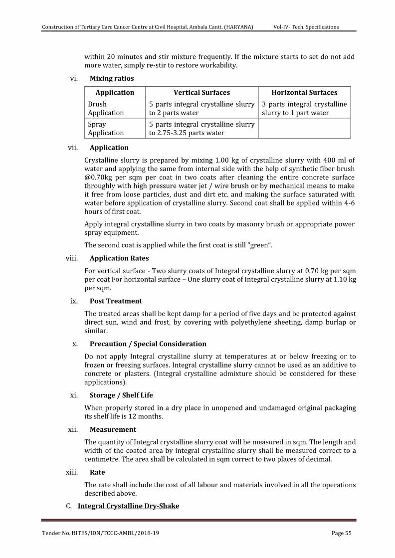
Construction of Tertiary Care Cancer Centre at Civil Hospital, Ambala Cantt. (HARYANA) Vol-IV- Tech. Specifications
Tender No. HITES/IDN/TCCC-AMBL/2018-19 Page 55
within 20 minutes and stir mixture frequently. If the mixture starts to set do not add more water, simply re-stir to restore workability.
vi. Mixing ratios
Application Vertical Surfaces Horizontal Surfaces
Brush Application
5 parts integral crystalline slurry to 2 parts water
3 parts integral crystalline slurry to 1 part water
Spray Application
5 parts integral crystalline slurry to 2.75-3.25 parts water
vii. Application
Crystalline slurry is prepared by mixing 1.00 kg of crystalline slurry with 400 ml of water and applying the same from internal side with the help of synthetic fiber brush @0.70kg per sqm per coat in two coats after cleaning the entire concrete surface throughly with high pressure water jet / wire brush or by mechanical means to make it free from loose particles, dust and dirt etc. and making the surface saturated with water before application of crystalline slurry. Second coat shall be applied within 4-6 hours of first coat.
Apply integral crystalline slurry in two coats by masonry brush or appropriate power spray equipment.
The second coat is applied while the first coat is still “green”.
viii. Application Rates
For vertical surface - Two slurry coats of Integral crystalline slurry at 0.70 kg per sqm per coat For horizontal surface – One slurry coat of Integral crystalline slurry at 1.10 kg per sqm.
ix. Post Treatment
The treated areas shall be kept damp for a period of five days and be protected against direct sun, wind and frost, by covering with polyethylene sheeting, damp burlap or similar.
x. Precaution / Special Consideration
Do not apply Integral crystalline slurry at temperatures at or below freezing or to frozen or freezing surfaces. Integral crystalline slurry cannot be used as an additive to concrete or plasters. (Integral crystalline admixture should be considered for these applications).
xi. Storage / Shelf Life
When properly stored in a dry place in unopened and undamaged original packaging its shelf life is 12 months.
xii. Measurement
The quantity of Integral crystalline slurry coat will be measured in sqm. The length and width of the coated area by integral crystalline slurry shall be measured correct to a centimetre. The area shall be calculated in sqm correct to two places of decimal.
xiii. Rate
The rate shall include the cost of all labour and materials involved in all the operations described above.
C. Integral Crystalline Dry-Shake
Construction of Tertiary Care Cancer Centre at Civil Hospital, Ambala Cantt. (HARYANA) Vol-IV- Tech. Specifications
Tender No. HITES/IDN/TCCC-AMBL/2018-19 Page 56
i. Materials
Integral crystalline dry shake of hydrophilic in nature is a unique chemical treatment material for the waterproofing and protection of concrete. Integral crystalline dry shake has been specially formulated for dry-shake applications on horizontal concrete surfaces where greater impact and abrasion resistance is required. Packaged in the form of a dry powder compound, Integral crystalline dry shake consists of Portland cement, various active proprietary chemicals, and a synthetic aggregate hardener that has been crushed and graded to particle sizes suitable for concrete floors. Integral crystalline dry shake becomes an integral part of the concrete surface, thereby eliminating problems normally associated with coatings (e.g. scaling, dusting, flaking and delamination). The active chemicals react with the moisture in the fresh concrete causing a catalytic reaction, which generates a non-soluble crystalline formation within the pores and capillary tracts of the concrete.
ii. Technical Specification/Parameters
a. Material must fulfil the requirements of American concrete institute guidelines ACI-212-3R-10, the coefficient of permeability should be measured for penetration of water. Under hydrostatic pressure of 72.5 psi (5 bars) to 150 psi (10 bars) for 72 to 96 hours as per DIN 1048 Part V. Reduction of water penetration should be 50 to 90%.
b. Potable Water Compatibility: Nontoxic and suitable for use in potable water facilities – NSF Listed as per ANSI 61 listing.
c. Confirm to EN 1504-3 (For structural repairs – R3, Compressive strength > 25 Mpa), supplied from an approved manufacturing unit having CE approval conforming to EN 1504-3-R3.
d. The product has no corrosion effect on reinforcement steel according to test norm DIN V 18998. The maximum chloride content lies less than 0.1% and maximum alkali content less than 9.3%.
iii. Recommended Uses:-
Raft / Foundation Slabs, Below-grade Structures Sewage and Water Treatment Plants Traffic Bearing Surfaces Warehouse Floors Parking Structures etc.
iv. Directions for Application
a. Application Rates
Under normal conditions, the coverage rate for Integral crystalline dry shake is 0.60 kg per sqm depending on the degree of abrasion resistance required.
b. Application Procedure
Integral crystalline dry shake is to be sprinkled @ 0.60 kg per sqm over the PCC blinding, after fixing the reinforcement bars on the cured PCC so as to achieve positive side waterproofing below the raft concrete, as per the manufactures specification.
c. Curing
Curing is important and shall begin as soon as final set has occurred but before surface starts to dry. Conventional moist curing procedures such as water spray, wet burlap or plastic covers may be used. Curing shall continue for at least 48 hours.
v. Precaution / Special Consideration
Construction of Tertiary Care Cancer Centre at Civil Hospital, Ambala Cantt. (HARYANA) Vol-IV- Tech. Specifications
Tender No. HITES/IDN/TCCC-AMBL/2018-19 Page 57
For the best results when applying dry shake materials, the air content of the concrete shall not exceed 3% (a high air content can make it difficult to achieve a proper application).
In hot, dry, or windy conditions, it is advisable to use an evaporation retardant on the fresh concrete surface to prevent premature drying of the slab.
Chronic moving cracks or joints will require a suitable flexible sealant.
vi. Storage / Shelf Life
Integral crystalline dry shake must be stored dry at a minimum temperature of 45ºF (7ºC) and its shelf life is one year when stored under proper conditions.
vii. Measurement
The quantity of Integral crystalline dry shake sprinkled area shall be calculated in sqm correct to two places of decimal. The length and width of the sprinkled area shall be measured correct to a centimetre.
viii. Rate
The rate shall include the cost of all labour and materials involved in all the operations described above.
D. Crystalline Mortar
i. Materials
Crystalline mortar consists of Portland cement, specially treated quartz sand and a compound of active chemicals. The active chemicals react with moisture and the by-products of cement hydration to cause a catalytic reaction, which generates an insoluble integral crystalline complex. These crystalline complexes grow in the presence of water, block the capillaries of the concrete and minor shrinkage cracks, thus waterproofing it. Chemical activation begins when the powder is mixed with water and may take several days to completely block the capillaries depending on ambient temperature and environmental conditions.
ii. Technical Specification/Parameters
a. Material must fulfil the requirements of American concrete institute guidelines ACI-212-3R-10, the coefficient of permeability should be measured for penetration of water. Under hydrostatic pressure of 72.5 psi (5 bars) to 150 psi (10 bars) for 72 to 96 hours as per DIN 1048 Part V. Reduction of water penetration should be 50 to 90%.
b. Bond strength: ≥ 1.5 Mpa (Class – R3).
c. Potable Water Compatibility: Nontoxic and suitable for use in potable water facilities – NSF
d. Listed as per ANSI 61 listing.
e. Confirm to EN 1504-3 (For structural repairs – R4, Compressive strength > 45 Mpa), supplied from an approved manufacturing unit having CE approval conforming to EN 1504-3-R4.
f. The product has no corrosion effect on reinforcement steel according to test norm DIN V 18998. The maximum chloride content lies less than 0.1% and maximum alkali content less than 9.3%.
iii. Recommended Uses
Applied in conjunction with integral crystalline slurry coat for:
Construction of Tertiary Care Cancer Centre at Civil Hospital, Ambala Cantt. (HARYANA) Vol-IV- Tech. Specifications
Tender No. HITES/IDN/TCCC-AMBL/2018-19 Page 58
a. Installation of seal strips, reglets and coves at joints to assure water tightness
b. Patching of tie holes and faulty construction joints
c. Patching and filling of routed out cracks
d. Repairing of spalled and honeycombed areas
iv. Surface Preparation
All surfaces to be patched, repaired or sealed with crystalline mortar must be clean and sound. Cracks shall be routed out to a U-shaped configuration, approximately (20-25 mm) wide and a minimum of (20-25 mm) deep. Tie holes should be roughened prior to filling. Spalled and honeycombed areas must be thoroughly cleaned and chiselled back to sound concrete prior to repair. Remove all dirt, cement laitance, form release agents, curing compounds, paints, coatings, etc. by means of wet or dry sandblasting, high pressure water jet or other suitable mechanical means. Surfaces must be well moistened to a dull dampness at the time of application. The concrete should be damp with no wet seen on the surface.
v. Preparation of Material
For routed cracks, coves and non-moving joints, add water to crystalline mortar until a medium stiff, trowelable consistency is reached. The texture of the mix should be pliable enough to be trowelled into the cracks with some pressure, but not so pliable that it would run out or sag out of the crack. Approximate mixing ratio (by volume) is 4.5 parts powder to 1 part water. Alternatively,100 ml of water to 450 gm of crystalline mortar powder. For tie holes and pointing applications, add only a small amount of water. Mixed consistency should be that of “dry earth”, holding a shape when squeezed in your hand but easily crumbled when pressed between fingers. Mix only as much material as can be used within 20 minutes.
vi. Application
a. For sealing cracks and faulty construction joints, routed out/making U-shape groove size 25x25mm and then priming the surface with integral crystalline slurry @0.05 kg per running meter and while the surface is tacky filled the cavity upto surface crystalline mortar @1.50 kg per running meter. Once crystalline mortar is touch dry then finally applying two coats of integral crystalline slurry @0.05 kg per running meter per coat.
b. For repairing spalled & honeycombed areas, prepared the surface and chiesel back upto sound concrete and then primed the area with integral crystalline slurry @0.70 kg per sqm. and while the surface is tacky repair and level the honeycomb area with crystalline mortar @ 22.70 kg per sqm. for an average thickness of 10mm. Once crystalline mortar is touch dry then finally two coats of integral crystalline slurry @ 0.70kg per sqm. per coat.
c. For patching of tie rod holes, prepared tie rod hole surface and primed the area with integral crystalline slurry @ 0.07 kg per sqm and while the surface is tacky repair and filled the tie rod holes with crystalline mortar @ 0.040 kg per hole. The crystalline mortar shall be tightly rodded into tie holes or packed tightly. For 25x25x25 mm hole, use 0.040 kg per hole to fill the tie hole.
vii. Curing
Provide protection against extreme weather conditions such as heavy rain or freezing conditions during the setting period. Curing is not normally required except during hot, low humidity weather. In these conditions a light mist of water approximately 24 hours after the repair is completed will help to ensure a controlled cure. In extreme dry heat, water misting may be required more frequently.
Construction of Tertiary Care Cancer Centre at Civil Hospital, Ambala Cantt. (HARYANA) Vol-IV- Tech. Specifications
Tender No. HITES/IDN/TCCC-AMBL/2018-19 Page 59
viii. Precaution / Special Consideration
Crystalline mortar shall not applied at temperatures below 40ºF (4ºC), to a frozen substrate or if temperatures will drop below freezing during the curing period (approximately 24 hours). This product is not recommended for use in expansion or construction joints. Crystalline mortar can be applied in (13 mm) layers not exceeding 2.5 inch (approximately 6.5 cm) to prevent shrinkage cracks in the mortar.
ix. Storage / Shelf Life
Crystalline mortar shall be stored in a dry enclosed area off the ground at a minimum temperature of 45ºF (7ºC). Shelf life when stored in proper conditions in unopened, undamaged packaging is 12 months.
x. Measurement
Faulty construction joint will be measured by measuring the length in running meter correct to a centimetre.
Repair of honeycombed area will be measured in square meter correct to two places of decimal by measuring the length and width of treated area correct to a centimetre.
Repair of tie rod holes will be measured in numbers.
xi. Rate
The rate shall include the cost of all labour and materials involved in all the operations described above.
33. SAMPLES OF MATERIALS:
a. Sample of all materials/ fittings and fixture to be used in the work such as doors, windows, tiles, sanitary, water supply, drainage fittings and fixtures shall be submitted well in advance by the contractor for approval from the Engineer-in charge of work in writing before placing orders for the entire quantity required for completion of work. Samples approved by the EIC shall be kept in Sample Room under the charge of Engineer-in-Charge and shall retain till completion of work.
b. Finished items in respect of typical portion of works of repetitive nature such as typical room, toilet, railing, door, window or any other work desired by the engineer-in- charge shall be prepared by the contractor to the satisfaction of Engineer-in – charge and got approved from him in writing before the commencement of these items for the entire work.
c. The requirements for preparation of samples shall be observed and fulfilled by the contractor well in advance to avoid any detriment to the general progress of work. In other words, this will not be allowed to have any effects on the general progress of work or on any of the terms and conditions of the contract. No claims of any kind whatsoever including the claims of extension of time will be entertained due to the incorporation of this requirement.
34. GRIHA requirements:
Materials shall be procured by the contractor keeping in view the recycled content to conform the GRIHA requirements as detailed in SCC and elsewhere.
35. VARIATION IN CONSUMPTION OF MATERIALS:
The variation in consumption of material shall be governed as per CPWD specification and clauses of the contract to the extent applicable.
Construction of Tertiary Care Cancer Centre at Civil Hospital, Ambala Cantt. (HARYANA) Vol-IV- Tech. Specifications
Tender No. HITES/IDN/TCCC-AMBL/2018-19 Page 60
36. MISCELLANCEOUS:
Materials manufacture by reputed firms and approved by Engineer – in charge shall only be used. Only articles classified as “First Quality” by the manufactures shall be used unless otherwise specified. Preference shall be given to those articles which bear ISI certification marks. In case articles bearing ISI certification marks are not available the quality of sample brought by the contractor shall be judged by the standards laid down in the latest CPWD specifications. For items not covered by the latest CPWD specification, relevant ISI standards shall apply.
37. TESTS:
a. Materials brought at site of work shall not be used in the work before getting satisfactory test results for Mandatory tests as per relevant provisions in Latest CPWD Specifications for works. Normally, part rate payment shall be allowed in the running account bills only if the materials are tested and test results are found to be satisfactory to by the Engineer-in-charge. These tests shall be got done from laboratories approved by Engineer-in - charge or the laboratory set up by the contractor at site as per directions of Engineer-in - charge.
b. The Engineer-in - charge of work shall check the test results and satisfy himself before allowing any payment in the running /final bill.
Construction of Tertiary Care Cancer Centre at Civil Hospital, Ambala Cantt. (HARYANA) Vol-IV- Tech. Specifications
Tender No. HITES/IDN/TCCC-AMBL/2018-19 Page 61
CHAPTER- 3
TECHNICAL SPECIFICATIONS PLUMBING & SANITARY WORKS
SECTION 1 GENERAL REQUIREMENT
1. Scope of work
The work shall in general conform to the Latest CPWD Specifications for works as mentioned in Schedule ‘F’ of the GCC. Work under this Contract shall consist of furnishing all labour, materials, equipment and appliances necessary and required. The Contractor is required to completely furnish all the plumbing and other specialized services as described hereinafter and as specified in the schedule of quantities and/or shown on the plumbing drawings.
SECTION 2 PLUMBING FIXTURES
1. Scope of work
a. Work under this Part shall consist of furnishing all materials & labour necessary and required to completely install all sanitary fixtures, chromium plated fittings and accessories as required by the drawings and specified in the Bill of Quantities.
b. Without restricting to the generality of the foregoing the sanitary fixtures shall include the following:-
i. Sanitary fixtures
ii. Bath tubs, shower trays
iii. Chromium plated fittings
iv. Porcelain or stainless steel sinks
v. Accessories e.g. towel rods, toilet paper holders, soap dish etc.
vi. Whether specifically mentioned or not, the rates quoted for the installation of the fixtures, appliances and accessories shall be provided with all fixing devices, nuts, bolts, screws, hangers ,fasteners as required.
vii. All exposed pipes within toilets and near fixtures shall be chromium plated brass or copper unless otherwise specified.
2. General
a. All sanitary fixtures, CP Fittings and CP/SS accessories shall be supplied at site of work as per manufacturers’ standard supply.
b. All fixtures and fittings shall be provided with all such accessories and fixing devices as are required to complete the item in working condition, even if the same is not specifically mentioned the Bill of Quantities, Specifications or shown on the drawings. The rate quoted will include all devices for proper fixing arrangement, nuts, bolts, screws and required connection pieces etc.
c. Fixing screws shall be half round head stainless steel wood screws or bolts with Stainless Steel washers. Iron screws rust and will not be permitted.
d. All fittings and fixtures shall be fixed in a neat workmanlike manner true to level and heights shown on the drawings and in accordance with the manufacturer’s recommendations. Care shall be taken to fix all inlet and outlet pipes at correct positions.
Construction of Tertiary Care Cancer Centre at Civil Hospital, Ambala Cantt. (HARYANA) Vol-IV- Tech. Specifications
Tender No. HITES/IDN/TCCC-AMBL/2018-19 Page 62
Faulty locations shall be made good and any damage to the finished floor, tiling or terrace shall be made good at Contractor's cost.
e. Contractor shall provide poly-sulphide sealant appropriate for its use for all fixtures fixed near wall, marble core seal and edges.
3. Water Closets
a. European W.C.
i. W.C. shall be any one of the following types:
a. Wall hung wash down or
b. single or double siphon type or
c. As per BOQ
ii. Each W.C. set shall be provided with an approved type of plastic/wooden seat of approved finish compatible and fitting appropriately with the WC set with rubber buffers and hinges. The WC seat shall be those approved and accepted for fixing on a particular type of WC.
iii. The seat shall be so fixed that it remains absolutely stationary in vertical position without falling down on the W.C.
iv. The edge between the fixture and the wall shall be sealed with approved type of poly-sulphide sealant.
b. Health faucet/spray (Optional)
A chromium plated spray with integral hand control valve and connected to a flexible pipe and angle valve with wall flange and hook are fixed as shown on the drawings or directed by the Engineer-in-charge. The angle valve and flange shall be paid under relevant item with abulation tap.
4. Wash Basins
a. Wash basins shall wall mounted type or for under over/counter installation as specified in the BOQ.
b. Each basin shall be supported on MS galvanized or painted C.I. brackets and the basin securely fixed to wall or under/above counter installation. The design of the brackets shall suit the basin selected and as recommended by the manufacturer.
c. Each basin shall be provided with 32 mm dia. C.P. waste with overflow/ pop-up or standard waste with rubber plug and chain, 32 mm dia. C.P. brass bottle trap with CP pipe to wall and flange as specified in the BOQ.
d. Each basin shall be provided with a single tap a hot & cold CP mixer with or without pop up waste fittings, 32 mm dia. CP cast brass bottle trap with outlet pipe and wall flange.
e. The edge between the fixture and the wall or the counter shall be sealed with approved type of poly-sulphide sealant
f. Washbasins shall be fixed at proper heights as shown on drawings. If height is not specified, the rim level shall be 79 cm or as directed by Engineer-in-charge.
g. Each washbasin connection (separately for hot and cold) shall be provided with angle valves with CP wall flange and CP connecting pipe and of required length.
5. Sinks
a. Sinks used shall be of any of the following types:
Construction of Tertiary Care Cancer Centre at Civil Hospital, Ambala Cantt. (HARYANA) Vol-IV- Tech. Specifications
Tender No. HITES/IDN/TCCC-AMBL/2018-19 Page 63
b. For kitchens, pantries, and designated utility rooms the sinks shall be stainless steel sinks with or without drain boards.
c. Each sink shall be supported by MS galvanized or painted C.I. brackets and clips and the basin securely fixed to wall or on the counter. The design of the brackets shall suit the basin selected and as recommended by the manufacturer.
d. Stainless steel sinks shall be provided with 40 mm dia. C.P. basket waste with plug (as supplied by manufacturer), 40 mm dia. C.P. brass “P” trap with CP pipe to wall and flange.
e. Each sink shall be provided with hot & cold CP mixer with approved type of a neck spout or individual taps as directed by the Engineer-In-Charge.
6. Shower set
a. Shower set shall comprise of hot & cold water mixer, C.P. shower arm with wall flange and shower head adjustable type.
b. Mixer shall be exposed type, single lever, concealed stop cocks with diverter and spout as selected by the Engineer-in-charge.
7. Accessories
a. Accessories shall be of any of the following types:
i. Towel rails
ii. Towel rings
iii. Coat hooks
iv. Soap dispensers
v. Soap dishes
b. Accessories shall be fixed with stainless steel half round head screws and cup washers in wall with rawl plugs or nylon sleeves and shall include cutting and making good.
c. Porcelain accessories shall be fixed in walls and set in cement mortar 1:2 (1 cement: 2 coarse sand) and fixed in relation to the tiling work. The flange of the recessed fixture shall cover the recess in the wall fully.
8. Measurement & Rates
a. Sanitary fixtures shall be measured by numbers or as specified in BOQ.
b. Rates for all items mentioned above shall be inclusive of cutting holes and chases and making good the same, stainless steel screws, nuts, bolts, fastener and any fixing arrangements required and recommended by manufacturers, testing and commissioning.
SECTION 3 Soils, Waste, Vent & Rainwater Pipes & Fittings
1. Scope of work
a. Work under this Part shall consist of furnishing all labour, materials, equipment’s and appliances necessary and required to completely install all soil, waste, vent and rainwater pipes and fittings as required by the drawings, and given in the Schedule of Quantities.
b. Without restricting to the generality of the foregoing, the system shall include the following:-
i. Vertical and horizontal soil, waste, vent and rain water pipes, and fittings, joints, clamps and connections to fixtures.
Construction of Tertiary Care Cancer Centre at Civil Hospital, Ambala Cantt. (HARYANA) Vol-IV- Tech. Specifications
Tender No. HITES/IDN/TCCC-AMBL/2018-19 Page 64
ii. C.I. soil & uPVC rainwater pipes.
iii. Connection of all pipes to sewer lines as shown on the drawings at ground floor levels.
iv. Floor and urinal traps, cleanout plugs, inlet fittings and rainwater heads/Khurras.
v. Testing of all pipe lines.
2. General requirements
a. All materials shall be new of the best quality conforming to specifications and subject to the approval of Engineer-in-charge.
b. Pipes and fittings shall be fixed truly vertical, horizontal or in slopes as required in a neat workmanlike manner.
c. Pipes shall be fixed in a manner as to provide easy accessibility for repair and maintenance and shall not cause obstruction in shafts, passages etc.
d. Pipes shall be securely fixed to walls and ceilings by suitable clamps intervals specified.
e. Access doors for fittings and cleanouts shall be so located that they are easily accessible for repair and maintenance.
3. Piping System
a. Soil, Waste & Vent Pipes
i. The Soil & Waste pipe system above ground has been planned as a "two pipe system" as defined in BIS: having separate pipes for waste for kitchen sinks, showers, washbasins, AHU's condensate drains and floor drains and is approved by Engineer-in-charge.
ii. All waste water from AHU's plant and pump rooms, floor channels in basements will be provided with a deep seal trap before connecting to the main drain or vertical stack.
iii. Vertical soil & waste stacks shall be connected to a common horizontal drain pipe at basement ceiling or to an external manhole directly where feasible and shown on the drawings.
b. Rainwater Pipes
i. All terraces shall be drained by providing down-takes rainwater pipes.
ii. Rainwater pipes are separate and independent and connected to the storm water drainage system as shown on the drawings.
iii. Rainwater in enclosed courtyards shall be collected in catch-basins and connected to storm water harvesting chambers as shown in drawings..
iv. Any dry weather flow from waste appliances, AHU's pump rooms, shall not be connected to the sewerage system.
c. Balcony/Planter drainage
All balconies, terraces, planters and other formal landscape areas will be drained by vertical down takes as per the landscape/architectural drawings and details.
d. Cast iron pipes & fittings (for Soil, waste, anti-siphon age pipes)
i. All pipes shall be straight and smooth and inside free from irregular bore, blow holes, cracks and other manufacturing defects. Pipes shall be centrifugally spun iron soil pipes conforming to sand cast to I.S. 3989.
ii. Standard weight dimensions shall be as follows:-
Construction of Tertiary Care Cancer Centre at Civil Hospital, Ambala Cantt. (HARYANA) Vol-IV- Tech. Specifications
Tender No. HITES/IDN/TCCC-AMBL/2018-19 Page 65
a. Sand Cast Iron Pipes & Matching Fitting shall be in conformity to I.S. 1729
b. Centrifugally cast (spun) iron pipes and fittings in conformity to I.S. 3989
e. uPVC pipes & fittings (For Rain Water Pipes etc.)
i. Where specified, Polythene pipes shall be uPVC pipes confirming to I.S: 4985-1988. The details of the nominal outer diameter, weight and working pressure shall be as per the standards, for the respective pressure rating as specified in the B.O.Q.
ii. Polythene pipes may be cold bending to a radius of not less than eight times of their external diameter. Pipes bent for smaller radius may be made by hot bending.
iii. Fittings used for Polythene pipes shall be compression moulded fittings matching to the above specifications.
f. Jointing
i. All Polythene pipes shall be Drip seal/Sealant and jointed as per manufacturer’s specifications and relevant I.S codes.
ii. All pipes shall be tested after installation for a pressure equal to twice the maximum working pressure in the line as per manufacturer’s specifications.
g. Fittings
1. Fittings shall conform to the same Indian Standard as for pipes. Pipes and fittings must be of matching IS Specification. Interchange of pipes of one standard with fittings on the other standard will not be permitted.
2. Fittings shall be of the required degree of curvature with or without access door.
3. Access door shall be made up with 3 mm thick insertion rubber washer and white lead.The bolts shall be lubricated with grease or white lead for easy removal later.The fixing shall be air and water tight.
h. Fixing
1. All vertical pipes shall be fixed by structural support clamps truly vertical. Branch pipes shall be connected to the stack at the same angle as that of the fittings. No collars shall be used on vertical stacks. Each stack shall be terminated at top with a cowl (terminal guard).
2. Horizontal pipes running along ceiling shall be fixed on structural adjustable clamps (Clevis clamps) of special design shown on the drawings or as directed. Horizontal pipes shall be laid to uniform slope and the clamps adjusted to the proper levels so that the pipes fully rest on them.
3. Contractor shall provide all sleeves, openings, hangers, inserts during the construction. He shall provide all necessary information to the Engineer-In-Charge/Building Contractor for making such provisions in the structure as necessary. All damages shall be made good to restore the surfaces.
4. Traps
a. Floor traps
Floor traps shall be siphon type full bore P or S type cast iron having a minimum 50 mm deep seal. The trap and waste pipes shall be set in cement concrete blocks firmly supported on the structural floor. The blocks shall be in 1:2:4 mix (1 cement :2 coarse sand : 4 stone aggregate 20 mm nominal size) and extended to
Construction of Tertiary Care Cancer Centre at Civil Hospital, Ambala Cantt. (HARYANA) Vol-IV- Tech. Specifications
Tender No. HITES/IDN/TCCC-AMBL/2018-19 Page 66
40 mm below finished floor level. Contractor shall provide all necessary shuttering and centring for the blocks. Size of the block shall be 30x30 cm of the required depth.
b. Urinal traps
Urinal traps/horn shall be cast iron P or S traps with or without vent and set in cement concrete block specified for floor traps.
c. Floor trap inlet
Bath room traps and connections shall ensure free and silent flow of discharging water.Wherespecified,Contractor shall provide a special type inlet fitting fabricated from G.I. pipe without, with one, two or three inlet sockets welded on side to connect the waste pipe. Joint between waste and hopper inlet socket shall be Drip Seal. Inlet shall be connected to a C.I. P or S trap. Floor trap inlet hoppers and the traps shall be set in cement concrete blocks as specified in para above without extra charge.
d. Gratings for traps
Floor and urinal traps shall be provided with 100-150mm square or round C.P. /Stainless steel grating /PTMT, with rim of approved design and shape as per BOQ.
e. Jointing
Soil, waste, vent and anti-siphonage pipes shall be jointed with Lead joint/ Drip seal joint as mentioned in the BOQ. The following minimum procedures shall be complied with while making the pipe joints:-
i. Ensure that the pipes are clean internally and undamaged.
ii. The pipes shall be cut square with sharp tools.
iii. The cut ends of the pipes shall be filed/ reamed and finished smooth.
iv. Any deformed ends shall be re-rounded.
v. It shall be ensured that the pipe ends shall enter the fittings and sockets to full depth of the jointing area.
vi. The pipe work shall be assembled in a manner such that it does not entail making of joints in restricted locations.
vii. Each metal pipe spigot shall be centered with three lightly wedged pieces of hardwood or folded lead.
viii. The jointing surfaces shall be cleaned to remove any coatings or cutting oils, etc.
f. Floor Trap Inlet/GI Inlet Fitting:
Traps and connections shall ensure free and silent flow of discharging water. Where specified, Contractor shall provide a special type cast iron or G.I. inlet hopper without or with one or two or three inlet sockets to receive the waste pipe. Joint between G.I. waste pipe and hopper inlet socket shall be Drip seal joint. Hopper shall be connected to a CI ‘P’ or ‘S’ trap with at least 50mm seal (hopper and traps shall be paid for separately). Floor trap inlet hoppers and the traps shall be set in cement concrete blocks/and supports as required for Floor trap above shall be provided without any extra charge.
5. Cleanout Plugs
a. Cleanout Plug on soil pipes
Construction of Tertiary Care Cancer Centre at Civil Hospital, Ambala Cantt. (HARYANA) Vol-IV- Tech. Specifications
Tender No. HITES/IDN/TCCC-AMBL/2018-19 Page 67
Clean out plug for Soil, Waste or Rainwater pipes laid under floors shall be provided near pipe junctions bends, tees, “Ys” and on straight runs at such intervals as required as per site conditions. Cleanout plugs shall terminate flush with the floor levels. They shall be threaded and provided with key holes for opening. Cleanout plugs shall be Cast Brass suitable for the Pipe dia. With screwed to a G.I. socket. The socket shall be Drip seal caulked to the drain pipes.
b. Cleanout Plug on Drainage Pipes
i. Cleanout plugs shall be provided on starting point of each drain and in between at locations indicated on plans or directed by the Engineer-in-charge. Cleanout plugs shall be of size matching the full bore of the pipe but not exceeding 150 mm dia. Cleanout Plugs on drains of greater diameters shall be 150 mm dia. Fixed with a suitable reducing adapter.
ii. Cleanout Plug at Ceiling Pipes: - Cleanouts provided at ceiling level pipe shall be fixed to a CI flanged tail piece. The cleanout doors shall be specially fabricated from light weight galvanised sheets and angles with hinged type doors with fly nuts, gasket etc., as per drawing.
6. Waste pipe from appliances
a. General
i. Waste pipe from appliances e.g. washbasins, sinks and urinals shall be of heavy galvanized steel /CPVC as given in the Schedule of Quantities or shown on the drawings.
ii. All pipes shall be fixed in gradient towards the outfalls of drains. Pipes inside a toilet room shall be in chase unless otherwise shown on drawings. Where required pipes may be run at ceiling level in suitable gradient and supported on galvanized structural clamps. Spacing for clamps for such pipes shall be as per good engineering practice approved by the Engineer-In-Charge.
b. Galvanized pipes
Waste pipes from appliances shall be galvanized steel tubes conforming to I.S.1239 (Heavy class) and quality certificates shall be furnished. Pipes shall be provided with all required fittings e.g. tees, couplings, bends, elbows, unions, reducers, nipples, plugs. All G.I. waste pipes shall be terminated at the point of connection with the appliance with an outlet of suitable diameter. Pipes in chase shall be wrapped with bitumen tape and then painted with two coats of black bitumen paint. Exposed pipes with one coat of Zinc cromate with etch coating primer and two or more coats of synthetic enamel paint or as given in the Schedule of Quantities. Colour shall be as per the approved colour code.
7. Cast iron pipes for drainage
a. All drainage lines passing under building, in exposed position above ground e.g. basement ceiling etc. shall be cast iron pipes. Position of such pipes shall generally be shown on the drawings.
b. Cast iron pipes shall be spigot & socket (S&S) centrifugally spun iron pipes conforming to I.S. 1536. (Class LA). Quality certificates shall be furnished.
c. Fittings
Fittings used for C.I. drainage pipe shall conform to I.S. 1538 (Heavy class). Wherever possible, junction from branch pipes shall be made by a Y- tee.
Construction of Tertiary Care Cancer Centre at Civil Hospital, Ambala Cantt. (HARYANA) Vol-IV- Tech. Specifications
Tender No. HITES/IDN/TCCC-AMBL/2018-19 Page 68
d. Joints
i. Joints between pipes shall be made with pre-moulded rubber joints (Tyton Joints) supplied by the manufacturer to ensure compatibility and water tightness.
ii. Joints between pipes and fittings shall be made by caulked spun yarn dipped in tar and molten drip seal 45 mm deep by hammering with caulking tools.
8. Encasing pipe in Cement Concrete
Cast iron soil and waste pipes under floor in sunken slabs and in wall chases (when cut specially for the pipe) shall be encased in cement concrete 1:2:4 mix (1 cement : 2 coarse sand :4 stone aggregate 12 mm size) 75 mm in bed and all-round. When pipes are running well above the structural slab, the encased pipes shall be supported with suitable cement concrete pillars of required height at intervals of 1.8 m. Rate for concrete round pipes shall be inclusive of pillars, supports, shuttering and centring.
9. Painting
a. All cast iron, soil, waste vent, anti-siphon age and rainwater pipes in exposed location in shafts and pipe spaces shall be painted with two or more coats of synthetic enamel paint to over a priming coat to give an even shade.
b. Paint shall be of approved quality and shade. Where directed pipes shall be painted in accordance with approved pipe colour code.
c. G.I. waste pipes in chase shall be painted with two coats of bitumen paint, covered with polythene tape and a final coat of bitumen paint. Exposed pipes shall be painted with two or more coats of synthetic enamel paint over each priming coat.
d. C.I. soil and waste pipes below ground and covered in cement concrete or lead pipes shall not be painted.
10. Cutting and making good
a. Pipes shall be fixed and tested as building proceeds.
b. Contractor shall provide all necessary holes cut outs and chases in structural members as building work proceeds. Wherever holes are cut or left originally, they shall be made good with cement concrete 1:2:4 (1 cement: 2 coarse sand: 4 stone aggregate 20 mm nominal size) or brick work in cement mortar 1:2 (1 cement: 2 coarse sand) and the surface restored as in original condition.
11. Testing
a. Testing procedure specified below apply to all soil, waste and vent pipes above ground including C.I. LA pipes laid in basement ceiling.
b. Entire drainage system shall be tested for water tightness during and after completion of the installation. No portion of the system shall remain untested. Contractor must have adequate number of expandable rubber/bellow plugs, manometers, smoke testing machines, pipe and fitting work test benches and any other equipment necessary and required to conduct the tests. All testing shall be certified for its calibration by an approved laboratory.
Construction of Tertiary Care Cancer Centre at Civil Hospital, Ambala Cantt. (HARYANA) Vol-IV- Tech. Specifications
Tender No. HITES/IDN/TCCC-AMBL/2018-19 Page 69
c. All materials obtained and used on site must have manufacturer's hydraulic test certificate for each batch of materials used on the site. All testing equipment must be calibrated and shall carry certificate from an approved laboratory.
d. Testing soil, waste and rainwater pipes
i. Apart from factory test all pipes and fittings shall be hydraulically tested for a head of 3 m preferably on a specially set up work bench. After applying pressure, strike the pipe with a wooden pallet and inspect for blow holes and cracks. Pressure may be applied for about 2 minutes. Reject and remove all defective pipes.
ii. After installation all connections from fixtures, vertical stacks and horizontal drains including C.I. LA pipes shall be tested to a hydraulic pressure not exceeding 3 m. Such tests shall be conducted for each floor separately by suitable plugs.
iii. The entire installation shall be tested by smoke testing machine. The test can be conducted after the plumbing fixtures are installed and all traps have water seal or by plugging all inlets by bellow plugs. Apply dense smoke keeping the top of stack open an observe for leakages. Rectify or replace defective sections.
iv. After the installation is fully complete, it should be tested by flushing the toilets, running at least 20% of all taps simultaneously and ensuring that the entire system is self-draining, has no leakages, blockages etc. Rectify and replace where required.
e. Contractor shall maintain a test register identifying date and time of each area. All tests shall be conducted in presence of Engineer-in-charge and signed by both.
12. Measurements
a. General
i. Rates for all items quoted shall be inclusive of all work and items given in the specifications and Schedule of Quantities.
ii. Rates are applicable for the work under floors, in shafts at ceiling level area for all heights and depths.
iii. Rates are inclusive of cutting holes and chase in RCC and masonry work and making good the same.
iv. Rates are inclusive of pre testing, on site testing, of the installations, materials and commissioning of the works.
v. Pipes (Unit of measurement, linear meter to the nearest Centimetre) or as specified in CPWD specifications.
b. All C.I. Soil, waste, vent, anti-syphonage and rain water pipes shall be measured net when fixed correct to a centimetre including all fittings along its length. No allowance shall be made for the portions of pipe lengths entering the sockets of the adjacent pipes or fittings. The above will apply to both case i.e. whether pipes are fixed on wall face or pillars or embedded in masonry or pipes running at ceiling level.
c. Pipes shall be measured per running metre correct to a centimetre for the finished work which shall include fittings e.g. bends, tees, elbows, reducers, crosses, sockets, nipples and nuts. The length shall be taken along centre line of the pipes and fittings. All pipes and fittings shall be classified according to their diameter, method of jointing and fixing substance, quality, and finish. The diameters shall be nominal
Construction of Tertiary Care Cancer Centre at Civil Hospital, Ambala Cantt. (HARYANA) Vol-IV- Tech. Specifications
Tender No. HITES/IDN/TCCC-AMBL/2018-19 Page 70
diameter of internal bore. The pipes shall be described as including all cutting and waste. In case of fittings of unequal bore, the largest bore shall be measured.
d. Cement concrete around pipes shall be measured along the centre of the pipe line measured per linear metre and include any masonry supports, shuttering and centring cutting complete as described in the relevant specifications.
e. Slotted angles/channels shall include support bolts, nuts and clamps embedded in masonry walls with cement concrete blocks and nothing extra will be paid for making good the same.
f. Fittings
Unit of measurement shall be the number of pieces. Pipe fittings are included in the rate for pipes. Urinal traps, trap gratings, hoppers, cleanout plugs shall be measured by number per piece and shall include all items described in the relevant specifications and Schedule of Quantities.
g. Painting
Painting of pipes shall be measured per running metre and shall be inclusive of all fittings and clamps. No deduction for fittings shall be made.
h. Excavation for soil pipes
No payment shall be admissible with respect to excavation, refilling and disposal of surplus earth for cast iron soil and waste pipes laid below ground, in sunken slabs.
i. Engineer-in-charge’s decision with respect to the correct interpretation regarding mode of measurement shall be final and binding on the contractor.
SECTION 4 Water Supply Systems
1. Scope of work
a. Work under this section consists of furnishing all labour, materials equipment and appliances necessary and required to completely install the water supply system as required by the drawings, specified hereinafter and given in the Schedule of Quantities.
b. Without restricting to the generality of the foregoing, the water supply system shall include the following:-
i. Rising main from water supply pumps to all overhead tanks.
ii. Distribution system from overhead tank to all fixtures and appliances for cold & hot water.
iii. Insulation to hot water pipes within toilets.
iv. Connections to all plumbing fixtures, and appliances.
2. General requirements
a. All materials shall be new of the best quality conforming to specifications. All works executed shall be to the satisfaction of the Engineer-in-charge.
b. Pipes and fittings shall be fixed truly vertical, horizontal or in slopes as required in a neat workmanlike manner.
c. Short or long bends shall be used on all main pipe lines as far as possible. Use of elbows shall be restricted for short connections.
Construction of Tertiary Care Cancer Centre at Civil Hospital, Ambala Cantt. (HARYANA) Vol-IV- Tech. Specifications
Tender No. HITES/IDN/TCCC-AMBL/2018-19 Page 71
d. As far as possible all bends shall be formed by means of a hydraulic pipe bending machine for pipes up to 25 mm dia. Bends and elbows may be used for pipe dia. greater than 32 mm.
e. Pipes shall be fixed in a manner as to provide easy accessibility for repair and maintenance and shall not cause obstruction in shafts, passages etc.
f. Pipes shall be securely fixed to walls and ceilings by suitable clamps at intervals approved by the Engineer-In-Charge.
g. Valves and other appurtenances shall be so located as to provide easy accessibility for operations, maintenance and repairs.
3. Water Supply System
a. Contractor should study the site plan and water supply system diagram for overviews of the system.
b. Source
i. Water supply will be acquired from HITES’s mains line (water report enclosed).
ii. The rising mains will be connected to the main fire static tank and then overflow into the main domestic water tank located in basement.
c. Water supply piping for garden hydrant and sprinkler and irrigation system will be separate and independent connected to a different pumping system.
4. G.I/ CPVC Pipes & Fittings
a. All pipe inside the building and where specified, outside the building shall be galvanized / CPCV steel tubes conforming to I.S. 1239 of class specified. When class is not specified they shall be heavy class.
b. Fittings shall be malleable iron galvanized /CPCV of approved make. Each fitting shall have manufacturer’s trade mark stamped on it. Fittings for G.I. /CPCV pipe shall include couplings, bends tees, reducers, nipples, union and bushes. Fittings shall conform to I.S. 1879-(Section I to X).
c. Pipe and fittings shall be joined with screwed joints, after cutting a pipe with a hacksaw or a cutting machine care shall be taken to remove burr from the end of the pipe after reaming with a proper file.
d. Pipe threaded joints will be made by applying suitable grade of TEFLON tape used for drinking water supply.( Use of red and white lead sutli will not be permitted for screwed joints)
e. All pipes shall be fixed in accordance with layout and alignment shown on the drawings. Care shall be taken to avoid air pockets. G.I./CPCV pipes inside shall be fixed in wall chases well above the floor. No floor shall be run inside a sunken floor as far as possible. Pipes may be run under the ceiling or floors and other areas as shown on drawings.
f. Clamps
i. G.I/CPCV pipes in the shaft and other locations shall be supported by clamps of design approved by Engineer-In-Charge. Pipes in wall chases shall be anchored byhooks. Pipes at ceiling level shall be supported on structural clamps.
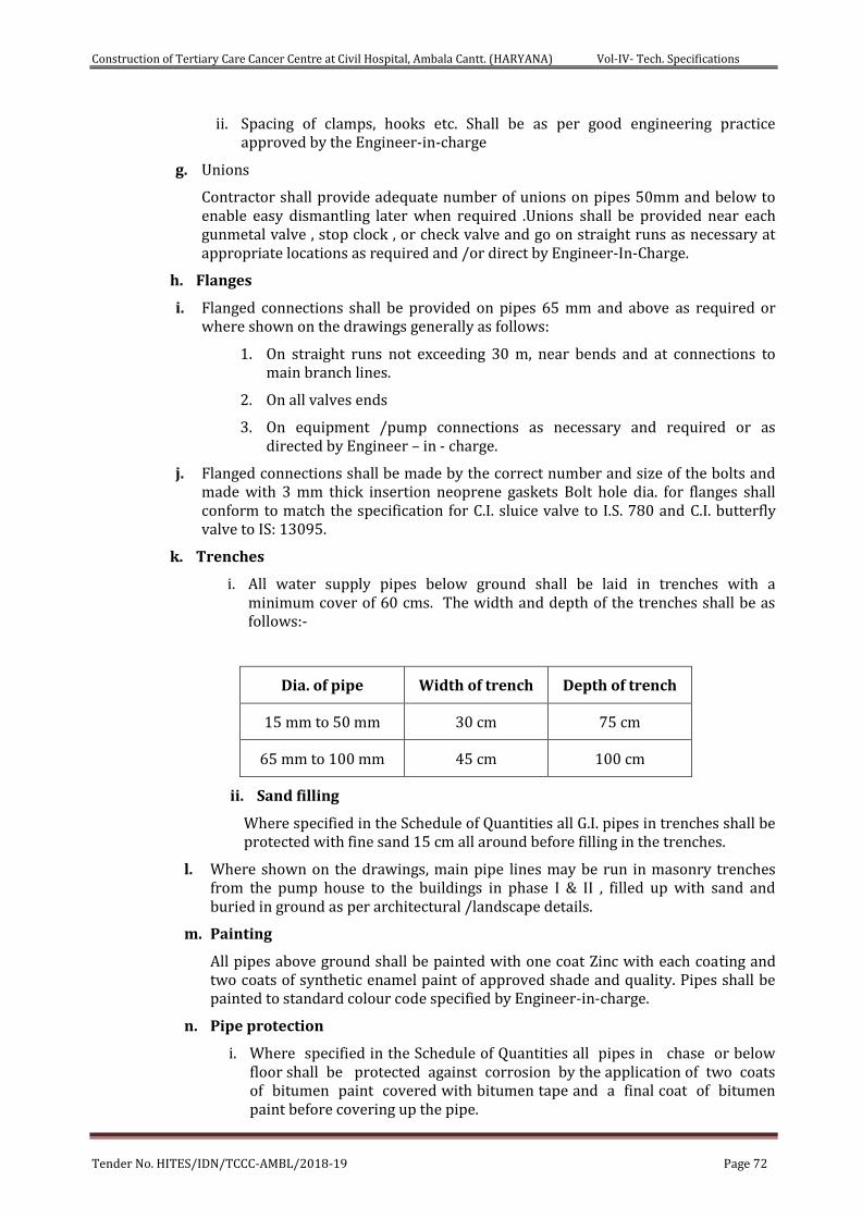
Construction of Tertiary Care Cancer Centre at Civil Hospital, Ambala Cantt. (HARYANA) Vol-IV- Tech. Specifications
Tender No. HITES/IDN/TCCC-AMBL/2018-19 Page 72
ii. Spacing of clamps, hooks etc. Shall be as per good engineering practice approved by the Engineer-in-charge
g. Unions
Contractor shall provide adequate number of unions on pipes 50mm and below to enable easy dismantling later when required .Unions shall be provided near each gunmetal valve , stop clock , or check valve and go on straight runs as necessary at appropriate locations as required and /or direct by Engineer-In-Charge.
h. Flanges
i. Flanged connections shall be provided on pipes 65 mm and above as required or where shown on the drawings generally as follows:
1. On straight runs not exceeding 30 m, near bends and at connections to main branch lines.
2. On all valves ends
3. On equipment /pump connections as necessary and required or as directed by Engineer – in - charge.
j. Flanged connections shall be made by the correct number and size of the bolts and made with 3 mm thick insertion neoprene gaskets Bolt hole dia. for flanges shall conform to match the specification for C.I. sluice valve to I.S. 780 and C.I. butterfly valve to IS: 13095.
k. Trenches
i. All water supply pipes below ground shall be laid in trenches with a minimum cover of 60 cms. The width and depth of the trenches shall be as follows:-
Dia. of pipe Width of trench Depth of trench
15 mm to 50 mm 30 cm 75 cm
65 mm to 100 mm 45 cm 100 cm
ii. Sand filling
Where specified in the Schedule of Quantities all G.I. pipes in trenches shall be protected with fine sand 15 cm all around before filling in the trenches.
l. Where shown on the drawings, main pipe lines may be run in masonry trenches from the pump house to the buildings in phase I & II , filled up with sand and buried in ground as per architectural /landscape details.
m. Painting
All pipes above ground shall be painted with one coat Zinc with each coating and two coats of synthetic enamel paint of approved shade and quality. Pipes shall be painted to standard colour code specified by Engineer-in-charge.
n. Pipe protection
i. Where specified in the Schedule of Quantities all pipes in chase or below floor shall be protected against corrosion by the application of two coats of bitumen paint covered with bitumen tape and a final coat of bitumen paint before covering up the pipe.

Construction of Tertiary Care Cancer Centre at Civil Hospital, Ambala Cantt. (HARYANA) Vol-IV- Tech. Specifications
Tender No. HITES/IDN/TCCC-AMBL/2018-19 Page 73
ii. All G.I. /CPVC water supply pipes below ground shall be protected against corrosion by applying one layer of 4 mm thick multilayer anticorrosive polymeric mix tape applied over a coat of primer as per recommendations of the manufacturers. (Pypcoat)
o. Insulation
Hot water pipes within a toilet /kitchen from hot water header shall be insulated with fire resistance closed cell chemically cross linked polyethene is used in the forms of rolls, sheets and tubes. The thickness of insulation is 13mm on all sizes of pipes. Density of insulation is 30±2kg/cum.
5. Valves
a. Ball valves
i. Valves 50 mm dia. and below shall be screwed type ball valves with stainless steel balls spindle Teflon seating and gland packing tested to a hydraulic pressure of 20 kg/cm2 and accompanying couplings and steel handles to B.S. 5351.
b. Butterfly Valves
i. Valves 65 mm dia. and above shall be cast iron butterfly valve to be used for isolation and/or flow regulation. The valves shall be bubble tight, resilient seated suitable for flow in either direction and seal in both direction. Valves shall be provided with matching flanges with neoprene insertion gasket 3 mm thick .P.N 1.6
ii. Butterfly valve shall be of best quality conforming to IS: 13095.
c. Non Return Valve
i. Where specified non return valve (swing check type) shall be provided through which flow can occur in one direction only, It shall be single door swing check type of best quality conforming to IS: 5312.P.N1.6
ii. Each butterfly and slim type swing check valves shall be provided with a pair of flanges screwed or welded to the main line and having the required number of galvanized nuts, bolts and double washers of correct length.
iii. Sluice valve shall be of approved makes conforming to I.S.:780 of class as specified.
6. Storage Tanks
a. Overhead Tanks
Overhead water storage tanks for water supply shall be reinforced cement concrete.
b. Tank connection and accessories
i. Contractor shall provide the following to each tanks:
1. Inlet and outlet connections to pumps, equipment and main pipe lines.
2. Tank overflows with mosquito proof gratings
3. Scour drain and valve as per drawings
4. Water level gauge with approved type of brass gauges, plastic tube, a wooden board with level marking.
ii. Electronic level controllers, cabling, sequence controllers and all related equipment shall be provided by agency executing the pumping system
Construction of Tertiary Care Cancer Centre at Civil Hospital, Ambala Cantt. (HARYANA) Vol-IV- Tech. Specifications
Tender No. HITES/IDN/TCCC-AMBL/2018-19 Page 74
work. Plumbing contractor shall provide necessary G.I. sleeves and co-operate with the contractor to ensure that the work is successfully executed.
7. Testing
a. All pipes, fittings and valves, after fixing at site, shall be tested by hydrostatic pressure of 1.5 times the working pressure or 10 kg /cm2 whichever is more. Pressure shall be maintained for a period of at least 12 hours without any drop & withstand for 8 hrs.
b. A test register shall be maintained and all entries shall be counter-signed by Contractor(s) in the presence of Engineer-in-charge.
c. In addition to the sectional testing carried out during the construction, Contractor shall test the entire installation after connections to the overhead tanks or pumping system or mains. He shall rectify all leakages and shall replace all defective materials in the system. Any damage done due to carelessness, open or burst pipes or failure of fittings, to the building, furniture and fixtures shall be made good by the Contractor during the defects liability period without any cost.
d. After commissioning of the water supply system, Contractor shall test each valve by closing and opening it a number of times to observe if it is working efficiently. Valves which do not effectively operate shall be replaced by new ones at no extra cost and the same shall be tested as above.
8. Measurements
a. G.I./CPVC pipes
i. G.I./CPVC pipes above ground shall be measured per linear metre (to the nearest cm) and shall be inclusive of all fittings e.g. couplings, tees, bends, elbows, unions, and flanges. Deduction for valves shall be made. Rate quoted shall be inclusive of all fittings, clamps, cutting holes chases and making good the same and all items mentioned in the specifications and Schedule of Quantities.
ii. G.I./CPVC pipes below ground shall be measured per linear metre (to the nearest cm) and shall be inclusive of fittings, e.g. couplings, tees, bends, elbows, unions. Deduction for valves shall be made. Rates quoted shall be inclusive of all fittings, excavation, back filling and disposal of surplus earth, cutting holes and chases and making good and all other items mentioned in the specifications and Schedule of Quantities.
b. Gunmetal, cast iron, butterfly and non-return valves puddle flanges, level indicators and meters shall be measured by numbers.
c. Brick masonry chamber for valves and meters shall be measured by number and include all items given in the Bill of quantities.
d. Painting/pipe protection
Painting/pipe protection for pipes shall be measured per linear metre over finished surface and shall include all valves and fittings for which no deduction shall be made.
e. Engineer-In-Charge’s decision with respect to the correct interpretation regarding mode of measurement shall be final and binding on the contractor.
Construction of Tertiary Care Cancer Centre at Civil Hospital, Ambala Cantt. (HARYANA) Vol-IV- Tech. Specifications
Tender No. HITES/IDN/TCCC-AMBL/2018-19 Page 75
SECTION – 5 Water Supply Pumping System & Allied services
1. Scope of work
a. Work under this section shall consist of furnishing all labour, materials, equipment and appliances necessary and required for the satisfactory supply, installation, completion and commissioning of water supply pumping system and allied works as described hereinafter, as specified in the schedule of quantities and/or shown on the plumbing drawings and described in the scope of work .
2. The System
a. The system described below is for the contractors bidding for the works to understand the extent and scope of work and the intent in the manner in which the water supply system is planned and shall be executed. This does not form a part of the contractor’s scope of work with respect to the various elements that are described in this paragraph.
b. Sources of supply
Local water supply for which a water main from the main road to the underground water tank will be laid by contractor.
c. Underground water tanks
i. Static fire water storage tanks in compartments .Connections from the tube well water supply lines will be made into these tanks. Water will overflow into the raw water tanks
ii. Raw Water Tank to hold the tube well as well as CWS Supply water will be made to:
1. A set of pumps will be connected to and water filter and chlorination system and the filtered water stored in the Treated Water Tanks (in three compartments. All piping and connections for this system are a part of this contract, if required.
2. Domestic Water Pumping Systems
iii. Water supply to the various buildings will be made from a set of pumping sets to the overhead water and supplementary fire tanks located on the terrace of each building.
3. Rising Mains & level control system
a. Water from the pumps described above will fill each tank by a rising main to each tower.
b. To control the level in each tank and enable it to fill as the water demand so requires, each tank will be provided with a ball cock to shut off the water supply when the tank is full.
c. A set of electronic level sensing probes will be installed in each tank. The probes installed in each pumping system will be wired to a central electronic panel which will activate the pump when any one of the tank probe signals low water conditions and top up all tanks. No excess flow will occur due to the ball cock in the tank.
Construction of Tertiary Care Cancer Centre at Civil Hospital, Ambala Cantt. (HARYANA) Vol-IV- Tech. Specifications
Tender No. HITES/IDN/TCCC-AMBL/2018-19 Page 76
4. Level Controllers
a. Level controllers shall be electronic magnetic type using required number of stainless steel type probes, shrouded in PVC sheath or encapsulated in a stainless steel pipe. The level controller will be used for following applications:-
i. Provide a audible high water alarm when water level in the sump reaches a pre-determined high level in the sump location at MCC panel installed in wall near sump location
b. Overhead tank level controller cum indicators
i. Each OHT to be provided with required number of stainless steel electronically operated probes (housed in a stainless steel protective housing) and connected by a control cable to a central junction box connected to MCC panel located in the pump house at basement. A common multi-core cable from each group of buildings will be laid to the pump room in basement.The probes will function as follows:
ii. To cut off the water supply pumps when all the OHT is full and to start the pump if any OHT level reaches at pre-determined low level.
iii. Provision shall be made to enable the operation of the second duty pump in case the water level does not rise above a pre-determined level in the tank due to water demand which is higher than capacity of duty pump no.1 to meet.
iv. Indicate the water level in each OHT in the level indicating panel installed in the pump room
v. Each OHT are also provided with a float valve to stop the supply in individual OHT when level reaches a cut off high level.
c. Control & Indicating Panel (For overhead and underground water tanks)
i. A centralized indicating stand–alone wall mounted panel fabricated from 14 g. with seven tank process MS sheet and painted inside and outside with stove enamelled finish with clear vertical panels for each group of buildings & tanks shall indicate water level in each tank by means of digital display unit to indicate water level in each tank in four levels (¼th, ½, ¾ and full). The panel shall be installed on the control console panel located in the pump room or as directed by the Project Engineer. The panel shall have:
ii. Digital level indicator panel meter for each water tank.
iii. Etched plate identification plates.
iv. Control cabling from MCC to the panel installed in the control room as directed by the Engineer-In-Charge.
v. Cabling from PHT sensing probes to the panel
5. Pressure filters for Water Supply System, if required.
a. Specification shall apply for water filtration system
i. Pressure filters shall be manufactured with factory made bobbin wound polyester fibre glass multilayer filters fitted with internal GI distribution pipe with polypropylene diffusers on top, collector pipes and arms, inlet and outlet header vertical water pressure dished ends complete with initial charge of filter media, G.I. face piping, accessories testing and
Construction of Tertiary Care Cancer Centre at Civil Hospital, Ambala Cantt. (HARYANA) Vol-IV- Tech. Specifications
Tender No. HITES/IDN/TCCC-AMBL/2018-19 Page 77
commissioning complete, Working Pressure 2.4 kg/cm2 (Test pressure 3.75 kg/cm2). Along with bfv & nrv & gauge, prv etc.
ii. Each vessel will be provided with suitable pressure tight manhole cover appropriately located for inspection and repairs.
iii. The diameter and height of each vessel shall be as per the design requirement and given in the BOQ and as per site conditions.
b. Multi-Port Valves
i. Each vessel will be provided with multi-port valves to operate and regulate the normal flow, backwash and rinsing, rapid washing, on the face piping.
ii. Provide suitable sampling cocks to draw water samples for raw water and treated water.
c. Face Piping
i. Each vessel shall be provided with non-corrosive face piping from the inlet to the outlet. Face piping shall be CPVC (IS 4985) 10 kg/cm2 all CPVC fittings are heavy grade to pipe and solvent weld and flanged joints
ii. All valves shall be butterfly valves as specified in the piping section over 65 mm dia. and for pipe dia. below 50 mm dia. shall be provided with ball valves.
d. Water Filtration Plant (For Domestic Water)
i. Design parameters for the proposed filter shall be as follows:
1. Filter media: - Graded aggregate of required size selected coarse and fine silica sand as per latest water treatment practice. Aggregate and sand to be acid washed and having purity of 99.9%.
2. Depth of filter media:- Approx. 750-900 mm deep (as per manufacturer’s design)
3. Back washing :- By air scouring through air blower (approx. 5.1 lpm/m2 of filter surface area and water supply from raw water pumps by reverse flow
4. Output Water Quality for Domestic Filters: To conform to IS 10500 for the relevant design criteria
e. Chemical Dosing Pumps
i. Pump applications
1. Chlorination of raw water from tube wells,
ii. Dosing system comprising of an electronic metering pump with, 100 lit capacity uPVC/HDPE solution tank with level gauge and lid on top.
iii. Electronic driven metering pumps with mechanically actuated diaphragm with oil lubricated gear mechanism. The output of the pump should be adjustable for operation from 10-100%. Pump construction shall be corrosion resistant polypropylene or similar material. Pump electrical circuit shall be interlocked with the main raw water /pool recirculation pumps so that they operate only when the pumps are operating.
f. Air Blower for Back Washing
Construction of Tertiary Care Cancer Centre at Civil Hospital, Ambala Cantt. (HARYANA) Vol-IV- Tech. Specifications
Tender No. HITES/IDN/TCCC-AMBL/2018-19 Page 78
i. Low pressure air blower with TEFC electrical motor, belt driven or direct drive, all mounted on a common structural based plate with oil and water separator.
ii. Air blowers will be used for back washing operations. The air blower shall be designed for operation of one filter at a time. Blowers will be designed for air flow of approx 5.1 lpm/m2 air capacity at 0.5 kg/cm2 pressure. (This may be modified to suit manufacturer’s requirement for filters offered.)
iii. The electrical switchgear shall be included in the respective MCC panel of the system
SECTION 6 Pipes & Fittings
1. Headers, piping and connections
a. All pipes within the plant room building in exposed locations and shafts including connections buried under floor and for suction and delivery headers shall be G.I. /CPVC pipes (medium class) and thickness specified. Pipes up to 150 mm dia. shall conform to I.S. 1239.
b. Pipe 200 mm dia. and above shall be G.I. ERW tubes to IS 3589. If black pipes are available they shall be galvanized before use.
c. Fittings for G.I. pipes shall be approved type malleable iron or wrought iron screwed galvanized fittings for screwed joints. Fittings 200 mm dia. may be shop fabricated but shall be shop galvanized after fabrication.
d. All M.S. structural supports and clamps shall be galvanised. All the pipe work within plant room shall be adequately supported with G.I. structural supports from floor or ceiling as required and directed by Engineer-In-Charge.
2. Jointing
a. G.I. Pipes (Screwed joints)
Pipe shall be provided with metal to metal threaded joints. Teflon tape shall be used for lubrication and rust prevention. (USE OF LEAD /ZINC BASED JOINTING COMPOUND ARE NOT PERMITTED)
b. Flanged joints / Dead Joints
a. Flanges shall be provided on:
i. Straight runs not exceeding 12-15 m on pipe lines 80 mm dia and above.
ii. Both ends of any fabricated fittings e.g. bends, tees etc. of 50 mm dia or larger diameter. (When Permitted)
iii. Both end of all suction delivery and other headers.
iv. For jointing valves, appurtenances, pumps, connections with pipes, to water tanks and other places necessary and required as good for engineering practice.
v. Flanges shall be as per applicable I.S. with appropriate number of G.I. nuts and bolts, 3 mm insertion rubber gasket complete.
vi. The cost of flanges is included in the rates of pipes along with fittings.
c. Unions
Construction of Tertiary Care Cancer Centre at Civil Hospital, Ambala Cantt. (HARYANA) Vol-IV- Tech. Specifications
Tender No. HITES/IDN/TCCC-AMBL/2018-19 Page 79
Provide approved type of dismountable unions on pipes lines 50 mm and below near valves or inspector test/drain and assemblies and as required as per site conditions.
d. Vibration Eliminators
All suction and delivery lines and as shown on the drawings double flanged reinforced neoprene bellow type flexible pipe connectors shall be provided. Connectors should be suitable for a working pressure of each pump and tested to the test pressure given in the relevant head. Length of the connectors shall be as per site requirements in accordance with manufacturer’s details.
3. Valves
a. Sluice valves
i. Full way Sluice Valves shall be used on the suction connection to pumps and headers.
ii. Sluice valves (80 mm dia. and above) shall be C.I. double flanged sluice valves with rising stem. Each sluice valve shall be provided with wheel in exposed positions and cap top for underground valves. Contractor shall provide suitable operating keys for sluice valves with cap tops.
iii. Sluice valves shall be of approved makes conforming to I.S.780 PN1.6 class
b. Butterfly Valves (PN 1.6 rating)
i. Butterfly Valves shall be used in all other locations as required conforming to IS 13095.PN 1.6
ii. They shall have a cast iron body.
iii. Disc shall be CI heavy duty electrolyses nickel plated abrasion resistant.
iv. The shaft to be EN-8 Carbon Steel with low friction nylon bearings.
v. The seat shall be drop tight constructed by bonding resilient elastomer inside a rigid backing.
vi. Built in flanged rubber seals.
vii. Actuator to level operated for valves above ground and T Key operated for valves below Ground.
viii. Built in flanges for screwed on flanged connections. Manufacturer’s details on fixing and Installation will be followed.
c. Non Return Valves (NRV PN 1.6 rating))
i. Non return valves will be used at location to allow flow only in one direction and prevent flow in the opposite direction.
ii. NRV shall be cast iron slim type with cast iron body and gunmetal internal parts and accompanying flanges. Valves shall conform relevant IS or match the butterfly valves.PN 1.6
iii. Built in flanges for screwed on flanged connections.
d. Ball Valves
Ball Valves up to 40 mm dia. shall be screwed type ball valves with stainless steel balls, spindle, Teflon seating and gland packing tested to a hydraulic pressure of 20 kg/cm2 and accompanying coupling and steel handles (to B.S. 5351.
4. ‘Y’ Strainers (PN 1.6 rating)
Provide cast iron ‘Y’ type strainers with gunmetal internal strainers, CI screwed plug to be provided on all water tank suction connections to pumps.
Construction of Tertiary Care Cancer Centre at Civil Hospital, Ambala Cantt. (HARYANA) Vol-IV- Tech. Specifications
Tender No. HITES/IDN/TCCC-AMBL/2018-19 Page 80
5. Measurements (Part 1, 2 & 3)
a. General
i. Unit rate for individual items, e.g., pressure tanks, MCC, level controller, water tank are for purposes of payments only. Piping, headers, valves, accessories, cabling and MCC to measured separately in this contract only.
ii. All items must include all accessories fittings as described in the specifications, BOQ and shown on the drawings.
b. Drainage Pumps & Sewage Pumps
Drainage pumps shall be measured by numbers and shall include all items as given in the specifications and schedule of quantities to provide a complete working system.
c. Level controllers & Alarms
Level controllers for each set of pumps shall be measured by number and inclusive of probes, cabling up to surface box near the pump and shall include all items as given in the specifications and schedule of quantities to provide a complete working system.
d. Piping Work
i. Suction and delivery headers for each pumping system shall be measured per set with required length and shall include all items as given in the schedule of quantities. Painting shall be included in rate of headers.
ii. CPVC pipes between various filters and units shall be measured per linear meter of the finished length and shall include all fittings, flanges, jointing, clamps for fixing to walls or hangers and testing. Flanges shall include 3 mm thick insertion rubber gasket, nuts, bolts and testing.
iii. Vibration eliminators, “Y” strainers, butterfly valves, slim non return valves, ball valves shall be measured by numbers and shall include all items as given in the schedule of quantities and specifications except from pump room.
SECTION 7 Specifications for Electrical Installation
1. Electrical Control Panels
a. General
i. All medium voltage switchboards shall be suitable for operation at three phase/three phase 4 wire, 415 volt, 50 Hz, neutral grounded at transformer system with a short circuit level withstand of 31 MVA at 415 volts or as per schedule of quantities.
ii. The Switch Boards shall comply with the latest edition with up to date amendments of relevant Indian Standards and Indian Electricity Rules and Regulations.
b. Switch Board Configuration
i. The Switch Board shall be configured with Air Circuit Breakers, MCCB's, and other equipment as called for in the Schedule of Quantities.
ii. The MCCB's shall be arranged in multi-tier formation whereas the Air Circuit Breakers shall be arranged in Single or Double tier formation only to facilitate operation and maintenance.
iii. The Switch Boards shall be of adequate size with a provision of 25% spare space to accommodate possible future additional switch gear.
Construction of Tertiary Care Cancer Centre at Civil Hospital, Ambala Cantt. (HARYANA) Vol-IV- Tech. Specifications
Tender No. HITES/IDN/TCCC-AMBL/2018-19 Page 81
c. Equipment Specifications
i. All equipment used to configure the Switch Board shall comply to the relevant Standards and Codes of the Bureau of Indian Standards and to the detailed technical Specifications as included in this tender document.
d. Constructional Features
i. The Switch Boards shall be metal enclosed, sheet steel cubicle pattern, extensible, dead front, floor mounting type and suitable for indoor mounting.
ii. The Switch Boards shall be totally enclosed, completely dust and vermin proof. Synthetic rubber gaskets between all adjacent units and beneath all covers shall be provided to render the joints dust and vermin proof to provide a degree of protection of IP 54 as specified. All doors and covers shall also be fully gasket with synthetic rubber and shall be lockable.
iii. The Switch Board shall be fabricated with CRCA Sheet Steel of thickness not less than 2.0 mm and shall be folded and braced as necessary to provide a rigid support for all components. The doors and covers shall be constructed from CRCA sheet steel of thickness not less than 1.6 mm. Joints of any kind in sheet metal shall be seam welded and all welding slag ground off and welding pits wiped smooth with plumber metal.
iv. All panels and covers shall be properly fitted and square with the frame. The holes in the panel shall be correctly positioned.
v. Fixing screws shall enter holes tapped into an adequate thickness of metal or provided with hank nuts. Self-threading screws shall not be used in the construction of the Switch Boards.
e. Switchboard Dimensional Limitations
i. A base channel 100 mm x 50 mm x 6 mm thick shall be provided at the bottom.
ii. A minimum of 200 mm blank space between the floor of switch board and bottom most units shall be provided.
iii. The overall height of the Switch Board shall be limited to 2300 mm.
iv. The height of the operating handle, push buttons etc shall be restricted between 300 mm and 2000 mm from finished floor level.
f. Switch Board Compartmentalisation
i. The Switch Board shall be divided into distinct separate compartments comprising.
ii. A completely enclosed ventilated dust and vermin proof bus bar compartment for the horizontal and vertical bus bars.
iii. Each circuit breaker and MCCB shall be housed in separate compartments enclosed on all sides.
iv. Sheet steel hinged lockable doors for each separate compartment shall be provided and duly interlocked with the breaker in "on" and "off" position.
v. For all Circuit Breakers separate and adequate compartments shall be provided for accommodating instruments, indicating lamps, control contactors and control MCB etc. These shall be accessible for testing and maintenance without any danger of accidental contact with live parts of the circuit breaker, bus bars and connections.
Construction of Tertiary Care Cancer Centre at Civil Hospital, Ambala Cantt. (HARYANA) Vol-IV- Tech. Specifications
Tender No. HITES/IDN/TCCC-AMBL/2018-19 Page 82
vi. A horizontal wire way with screwed cover shall be provided at the top to take interconnecting control wiring between vertical sections.
vii. Separate cable compartments running the height of the Switch Board in the case of front access Boards shall be provided for incoming and outgoing cables.
viii. Cable compartments shall be of adequate size for easy termination of all incoming and outgoing cables entering from top.
ix. Adequate and proper support shall be provided in cable compartments to support cables.
g. Switch Board Bus Bars
i. The Bus Bar and interconnections shall be of electrolytic Copper/ Aluminium and of rectangular cross sections suitable for full load current for phase bus bars and half rated current for neutral bus bar. The maximum current density for copper shall be 1.6 amps per sq. mm. and for Aluminium shall be 1 amp per Sq. mm. and suitable to withstand the stresses of a 31 MVA fault level or at 415 volts for 1 second or as per schedule of quantities.
ii. The bus bars and interconnections shall be insulated with insulation tape/ fibre glass.
iii. The bus bars shall be extensible on either side of the Switch Board.
iv. The bus bars shall be supported on non-breakable, non-hygroscopic insulated supports at regular intervals, to withstand the forces arising from a fault level of 31 MVA at 415 volts for 1 second.
v. All bus bars shall be colour coded.
vi. All bus bar connections in Switch Boards shall be bolted with brass bolts and nuts. Additional cross section of bus bars shall be provided wherever holes are drilled in the bus bars.
h. Switch Board Interconnections
i. All connections between the bus bars/Breakers/cable terminations shall be through solid tinned copper strips of adequate size to carry full rated current and PVC/fibre glass insulated.
ii. For unit ratings up to 100 amps PVC insulated copper conductor wires of adequate size to carry full load current shall be used. The terminations of all such interconnections shall be crimped and aluminium lugs shall be used.
i. Draw out Features
i. Air Circuit Breakers shall be provided in fully draw out cubicles. These cubicles shall be such that draw out is possible without disconnection of the wires and cables. The power and control circuits shall have self-aligning and self-isolating contacts. The fixed and moving contacts shall be easily accessible for operation and maintenance. Mechanical interlocks shall be provided on the draw out cubicles to ensure safety and compliance to relevant Standards. The MCCB's shall be provided in fixed type cubicles.
j. Instrument Accommodation
i. Instruments and indicating lamps shall not be mounted on the Circuit Breaker Compartment door for which a separate and adequate compartment shall be provided and the instrumentation shall be accessible for testing and maintenance without danger of accidental contact with live parts of the Switch Board.
Construction of Tertiary Care Cancer Centre at Civil Hospital, Ambala Cantt. (HARYANA) Vol-IV- Tech. Specifications
Tender No. HITES/IDN/TCCC-AMBL/2018-19 Page 83
ii. For MCCB's instruments and indicating lamps can be provided on the compartment doors.
iii. The current transformers for metering and for protection shall be mounted on the solid copper/aluminium bus bars with proper supports.
k. Wiring
All wiring for relays and meters shall be with PVC insulated copper conductor wires. The wiring shall be coded and labelled with approved ferrules for identification. The minimum size of copper conductor control wires shall be 1.5 sq. mm.
l. Cable Terminations
i. Knockout holes of appropriate size and number shall be provided in the Switch Board in conformity with the location of incoming and outgoing conduits/cables.
ii. The cable terminations of the Circuit Breakers shall be brought out to terminal cable sockets suitably located at the rear / top of the panel.
iii. The cable terminations for the MCCB's shall be brought out to the rear in the case of rear access switchboards or in the cable compartment in the case of front access Switch Boards.
iv. The Switch Boards shall be complete with tinned brass cable sockets, tinned brass compression glands, gland plates, supporting clamps and brackets etc for termination of 1100 volt grade aluminium conductor PVC/PVCA cables.
m. Space Heaters
The Switch Board shall have in each panel thermostatically controlled space heaters with a controlling 15 amp 230 volt switch socket outlet to eliminate condensation.
n. Ventilation Fans
The Switch Board shall be provided with panel mounting type ventilation fans in each panel with switchgear rated for 2500 amp and above. The fan shall be interlocked with switchgear operation.
o. Earthing
A main earth bar of G.I./copper as required shall be provided throughout the full length of the Switch Board with a provision to make connections to the can be tap from main earthing.
p. Sheet Steel Treatment and Painting
i. Sheet Steel materials used in the construction of these units should have undergone a rigorous rust proofing process comprising of alkaline degreasing, descaling in dilute sulphuric acid and a recognised phosphating process. The steel work shall then receive two costs of oxide filler primer before final painting. Castings shall be scrupulously cleaned and fettled before receiving a similar oxide primer coat.
ii. All sheet steel shall after metal treatment be spray or powder painted with two coats of shade 692 to IS 5 on the outside and white on the inside. Each coat of paint shall be properly stoved and the paint thickness shall not be less than 50 microns.
q. Name Plates And Labels
Suitable engraved white on black name plates and identification labels of metal for all Switch Boards and Circuits shall be provided. These shall indicate the feeder number and feeder designation.
Construction of Tertiary Care Cancer Centre at Civil Hospital, Ambala Cantt. (HARYANA) Vol-IV- Tech. Specifications
Tender No. HITES/IDN/TCCC-AMBL/2018-19 Page 84
2. Testing
Copies of type test carried out at ACB/MCCB manufacturers works and routine tests carried out at the switchboard fabricators shop shall be furnished along with the delivery of the switchboards. Engineer-In-Charge reserves the right to get the switchboard inspected by their representative at fabricators works prior to dispatch to site to witness the routine tests as per relevant clause of SCC
3. Testing at Site
a. Pre-commissioning tests as required and as per manufacturers recommendations shall be carried out on each switchboard at site before energizing the switchboards including but not restricted to the following.
i. Physical checking of the switchboards including checking alignment of panels, interconnection of Bus bars, tightness of bolts/connections and evidence of damage/cracks in any components.
ii. Physical checking and inspections of Inter panel wiring
iii. Checking free movement of ACBs/MCCBs/SFUs
iv. Checking of operation of breakers
v. Insulation tests of bus bar supports and control wiring etc. with 1.1 kV megger.
vi. Primary & secondary injection tests of relays and CTs.
vii. Checking of Interlocking function.
4. Cables
i. Medium Voltage Cables
a. Medium voltage cables shall be aluminium conductor PVC insulated, PVC sheathed armoured conforming to IS 1554. Cables shall be rated for a 1100 Volts. The conductor of cables from 16 Sq. mm. to 50 mm2 shall be stranded. Sector shaped stranded conductors shall be used for cables of 50 mm2 and above. Conductors shall be made of electrical purity aluminium 3/4 H or H temper. Conductors shall be insulated with high quality PVC base compound. A common covering (bedding) shall be applied over the laid up cores by extruded sheath of unvulcanised compound. Armouring shall be applied over outer sheath of PVC sheathing. The outer sheath shall bear the manufacturer's name and trade mark at every meter length. Cores shall be provided with following colour scheme of PVC insulation.
1 Core : Red/Black/Yellow/Blue
2 Cores : Red and Black
3 Cores : Red, Yellow and Blue
3.5/4 Cores : Red, Yellow, Blue and Black
b. Current ratings shall be based on the following conditions.
i. Maximum conductor temperature 70O C
ii. Ambient air temperature 45O C
iii. Ground temperature 30O C
iv. Depth of laying 1000 mm
c. Short circuit rating of cables shall be as specified in IS 1554 Part-I.
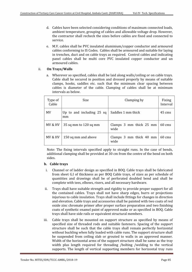
Construction of Tertiary Care Cancer Centre at Civil Hospital, Ambala Cantt. (HARYANA) Vol-IV- Tech. Specifications
Tender No. HITES/IDN/TCCC-AMBL/2018-19 Page 85
d. Cables have been selected considering conditions of maximum connected loads, ambient temperature, grouping of cables and allowable voltage drop. However, the contractor shall recheck the sizes before cables are fixed and connected to service.
e. M.V. cables shall be PVC insulated aluminium/copper conductor and armoured cables conforming to IS Codes. Cables shall be armoured and suitable for laying in trenches, duct and on cable trays as required. Control cables and indicating panel cables shall be multi core PVC insulated copper conductor and un armoured cables.
ii. On Trays/Walls
a. Wherever so specified, cables shall be laid along walls/ceiling or on cable trays. Cable shall be secured in position and dressed properly by means of suitable clamps, hooks, saddles etc. such that the minimum clear spacing between cables is diameter of the cable. Clamping of cables shall be at minimum intervals as below.
Type of Cable
Size Clamping by Fixing Interval
MV Up to and including 25 sq mm
Saddles 1 mm thick 45 cms
MV & HV 35 sq mm to 120 sq mm Clamps 3 mm thick 25 mm wide
60 cms
MV & HV 150 sq mm and above Clamps 3 mm thick 40 mm wide
60 cms
Note: The fixing intervals specified apply to straight runs. In the case of bends, additional clamping shall be provided at 30 cm from the centre of the bend on both sides.
b. Cable trays
i. Channel or of ladder design as specified in BOQ. Cable trays shall be fabricated from sheet G.I of thickness as per BOQ Cable trays, of sizes as per schedule of quantities and drawings shall be of perforated doubled bend and shall be complete with tees, elbows, risers, and all necessary hardware.
ii. Trays shall have suitable strength and rigidity to provide proper support for all the contained cables. Trays shall not have sharp edges, burrs or projections injurious to cable insulation. Trays shall include fittings for changes in direction and elevation. Cable trays and accessories shall be painted with two coats of red oxide zinc chromate primer after proper surface preparation and two finishing coats of synthetic enamel paint of approved make or as specified in BOQ. Cable trays shall have side rails or equivalent structural members.
iii. Cable trays shall be mounted on support structure as specified by means of specified size of threaded rods and suitable fasteners. Spacing of the support structure shall be such that the cable trays shall remain perfectly horizontal without buckling when fully loaded with cable runs. The support structure shall be suspended from ceiling slab or grouted to walls in an approved manner. Width of the horizontal arms of the support structure shall be same as the tray width plus length required for threading /bolting /welding to the vertical supports. The length of vertical supporting members for horizontal tray runs
Construction of Tertiary Care Cancer Centre at Civil Hospital, Ambala Cantt. (HARYANA) Vol-IV- Tech. Specifications
Tender No. HITES/IDN/TCCC-AMBL/2018-19 Page 86
shall be to suit the number of tray tiers required. Cable trays shall be bolted/ welded to the support structure. Minimum clearance between the top most tray tier and the ceiling shall be 300 mm. Trays shall be erected properly to present a neat and clean appearance. Trays shall be installed as a complete system. The entire cable tray system shall be rigid. Each run of cable tray shall be completed before laying of cables. Cable trays shall be erected so as to be exposed and accessible. Cables shall be fixed to the tray by clamps fabricated from minimum 3 mm thick GI sheets. The cables shall be dressed properly so as to provide minimum one cable diameter clearance between adjacent cables and from tray ends. Cable trays shall be earthed by 2 runs of 25 mm x 3 mm GI strips throughout their lengths.
5. LAYING OF CABLES
Cables shall be so laid that the maximum bending radius is 12 times the overall diameter of the cable for medium voltage cables. Cables shall be laid in masonry trenches, directly on walls/cable trays, directly buried in ground or in pipes/ducts as elaborated below. Cables of different voltages and also power and control cables shall be laid in different trenches with adequate separation. Wherever available space is restricted such that this requirement cannot be met, medium voltage cables shall be laid above HT cables. Where more than one cable is laid side by side, cable marker tags of approved type inscribed with cable identification details shall be permanently attached to cables at entry points to the building, at specified intervals for cables laid direct in grounds and in locations like manholes, pull pits etc.
6. Drawings
Shop drawings for control panels and wiring of equipment showing the route of conduit cable shall be submitted by the contractor for approval of Engineer-in-charge before starting the fabrication of panel and starting the work. On completion, all details like location of panels, switches, junction/pull boxes and cables route etc. shall be furnished by the contractor.
7. Measurement
Panels shall be counted as number of units. The quoted rate of panel shall also include all accessories, switch gear, fuses, contractor, indicating meters and lights as per the specification. Cable tray, Power & Control cable shall be measured in running meter.
SECTION 8 Commissioning and Guarantees
1. Scope of work
The work under this section shall consist of pre-commissioning, commissioning, testing and providing guarantees for all equipment, appliances and accessories supplied and installed by the contractor under this contract.
2. General requirements:
a. Work under this Part shall be executed without any additional cost. The rates quoted in this tender shall be inclusive of the works given in this Part
b. Contractor shall provide all tools, equipment, metering and testing devices required for the purpose.
c. On award of work, contractor shall submit a detailed proposal giving methods of testing and gauging the performance of the equipment to be supplied and installed under this contract.
3. Pre commissioning
Construction of Tertiary Care Cancer Centre at Civil Hospital, Ambala Cantt. (HARYANA) Vol-IV- Tech. Specifications
Tender No. HITES/IDN/TCCC-AMBL/2018-19 Page 87
a. On completion of the installation of all pumps, piping, valves, pipe connections, electrical wiring, motor control panels and water level controlling devices the contractor shall proceed as follows:-
i. Testing of M.C.C
ii. Tests to be carried out for motor control centres shall be:
iii. Insulation resistance test with 500 volt megger, before and after high voltage test, on all power and control wiring.
iv. High voltage test sat 2000 volts A.C. for one minute on all power and control wiring.
v. Low voltage continuity test (6 volts) on power wiring of each feeder, between bus bars and the outgoing terminals with switches and contactors in closed position.
vi. Low Voltage continuity test (6 volts) on all control wiring.
vii. Operation test for all feeders with only control supply made 'on' to ensure correctness of control wiring, operation of the various equipment used such as push buttons, protective devices, indicating lamps and relays etc. All contactors shall be checked and there shall be no chattering.
viii. Earth continuity test with voltage not exceeding 6 volts between various non-current carrying metallic parts of equipment, steel work etc. And the earth bus provided in the MCC.
ix. Operation of all instruments and meters provided on the MCC.
b. Pipe work
i. Check all clamps, supports and hangers provided for the pipes.
ii. Fill up pipes with water and apply hydrostatic pressure to the system as given in the relevant Part of the specifications. If any leakage is found, rectify the same and retest the pipes.
iii. Check all face piping and valves
iv. check air blower connections
4. Commissioning & testing
a. All pumping sets
Start the duty pump on manual controls, check its operation and then test run on auto controls. Change over the duty pump and test it in the same manner as the first pump.
b. Test runs the entire system to ensure satisfactory performance.
5. Handing Over
a. All commissioning and testing shall be done by the contactor to the complete satisfaction of the Engineer-In-Charge and the job handed over to the Engineer-In-Charge or his authorized representative.
b. Contractor shall also hand over, to the Engineer-In-Charge, all maintenance & operation manuals, 4 sets of As Built drawings and all other items as per the terms of the contract with soft copy.
6. Guarantees
Construction of Tertiary Care Cancer Centre at Civil Hospital, Ambala Cantt. (HARYANA) Vol-IV- Tech. Specifications
Tender No. HITES/IDN/TCCC-AMBL/2018-19 Page 88
a. The contractor shall submit a warranty for all equipment, materials and accessories supplied by him against manufacturing defects, malfunctioning or under capacity functioning.
b. The form of warranty shall be as approved by the Engineer-in-charge.
c. The warranty shall be valid for a period of one year from the after getting virtual completion certificate.
d. The warranty shall expressly include replacement of all defective or under capacity equipment. Engineer-In-Charge may allow repair of certain equipment if the same is found to meet the requirement for efficient functioning of the system.
e. The warranty shall include replacement of any equipment found to have capacity lesser that the rated capacity as accepted in the contract. The replacement equipment shall be approved by the Engineer-In-Charge.
f. The contractor shall separately submit with this offer his charges per month for operation of mechanical equipment(s) after commissioning and handing over.
SECTION 9 I.S. Codes
Following codes and Indian standards shall be applicable as amended up to date-
A. Electrical equipment
1. Marking & arrangement for switch gear bus bars, main connections and auxiliary wiring- I.S. 375
2. Direct acting electrical indicating instruments - I.S.1248
3. Metal enclosed switch gear and control gear - I.S. 3427
4. A.C. Contactors of voltage not exceeding 1000 volts. - I.S. 2959
5. A.C. Motor starters of voltage not exceeding 1000 volts. -I.S. 1822
6. Air breaks isolation for voltages not exceeding 1000 volts .-I.S. 2607
7. Heavy duty air break switches and composite unit of air break switches and fuses for voltage not exceeding 1000 volts. - I.S. 4047
8. PVC insulated cables (for voltage Up to 1100 volts with copper/ aluminium conductors)(Section I & II)- I.S. 694
9. Normal duty air break switches and composite units of air break switches and fuses for voltage not exceeding 1000 volts.-I.S. 4064
10. Code of practice for earthing - I.S. 3043
11. Pumps & motors
a. Centrifugal pumps -I.S. 1520
b. Electrical Motors - I.S.7538
12. Pipes
a. G.I. Pipes - I.S. 1239
13. Valves
a. Butterfly Valves -IS 23339/13095
b. Slim Type NRV -I.S. 7312
Construction of Tertiary Care Cancer Centre at Civil Hospital, Ambala Cantt. (HARYANA) Vol-IV- Tech. Specifications
Tender No. HITES/IDN/TCCC-AMBL/2018-19 Page 89
c. Sluice valve -I.S. 780
14. Vibration Eliminator
15. Water Shock Absorbers
16. Pipe Colour Code as per I.S. 2379-1983.
SECTION 10 Technical Information for Water Supply & Drainage Pumps to be furnished by Bidder:
i. Pumps
a. Make
b. Model
c. Pump Discharge - Max/Min
d. Pump Head Min/Max,
e. Impeller Material
f. Motor HP
(Specify make, class of insulation & rated voltage ± %)
g. Shaft Seal Type & make
h. Type of Coupling
i. Efficiency of Pump
j. Type of Bearings
k. RPM
ii. Pressure Tanks ( Where specified)
a. Make
b. Material of Construction
c. Internal finish
d. External finish
e. Air balloon/ diaphragm
f. specifications
iii. Submersible pumps- Plant Room- Sewage
a. Make
b. Model No.
c. Pump discharge lpm - max / min
d. Pump head min/max,
e. Impeller material
f. Motor HP (Specify make, class of insulation & rated voltage ± %)
g. Shaft seal Type & make
Construction of Tertiary Care Cancer Centre at Civil Hospital, Ambala Cantt. (HARYANA) Vol-IV- Tech. Specifications
Tender No. HITES/IDN/TCCC-AMBL/2018-19 Page 90
h. Type of coupling
i. Efficiency of pump
j. Type of bearings
k. RPM
iv. Motor Control Centres ( Give detail on separate sheets if required )
a. Make
b. Type (floor/wall mounted)
c. Make of switch gear
d. Make of meters
e. Make of accessories
f. Confirm that all switch gear starters match the capacities of pumps offered.
v. Power & control cables
a. Make
vi. Electronic Level controllers
a. Make
b. Model No.
vii. Electronic High Water Alarm
a. Make
b. Model No.
viii. Electronic Level Indicator
a. Make
b. Model
ix. Pipes /CPVC
a. Make offered
i. Heavy Class 150 mm dia. & below
ii. Heavy Class 200 mm dia. & above
b. CPVC Pipe
x. Butterfly Valves
a. Make
b. Material
Construction of Tertiary Care Cancer Centre at Civil Hospital, Ambala Cantt. (HARYANA) Vol-IV- Tech. Specifications
Tender No. HITES/IDN/TCCC-AMBL/2018-19 Page 91
c. Test pressure
xi. NRV Slim Type
a. Make
b. Material
c. Test pressure
xii. Vibration eliminators
a. Make
b. Material
c. Test pressure
xiii. Pressure
a. Working pressure
b. Test pressure
c. Filtration/holding Capacity
d. Inlet/outlet sizes
xiv. Painting/coating
a. Inside
b. Outside
xv. Equipment - Air Blower Chlorinator
a. Make
b. Model
c. Pump Discharge -Max/Min
d. Pump Head - Min/Max,
e. Impeller Material
f. Motor HP (Specify make, class of insulation & rated voltage ± %)
g. Shaft Seal
h. Type of Coupling
i. Efficiency of Pump
j. Type of Bearings
k. Speed of Pumps
xvi. Motor control centres
a. Type (floor/wall mounted)
Construction of Tertiary Care Cancer Centre at Civil Hospital, Ambala Cantt. (HARYANA) Vol-IV- Tech. Specifications
Tender No. HITES/IDN/TCCC-AMBL/2018-19 Page 92
b. Make of switch gear
c. Make of panel meters
d. Confirm that all switch gear starters are of capacities for pumps offered.
xvii. Pipe fitting scheduled.
xviii. C.I. Pipe
xix. RCC Pipe.
xx. L.A. Pipe.
xxi. HDPE Pipe.
xxii. Insulation Material
xxiii. Flow Meter.
xxiv. PRV
xxv. Hydro-pneumatic Pump.
xxvi. Water meter.
Construction of Tertiary Care Cancer Centre at Civil Hospital, Ambala Cantt. (HARYANA) Vol-IV- Tech. Specifications
Tender No. HITES/IDN/TCCC-AMBL/2018-19 Page 93
CHAPTER - 4
TECHNICAL SPECIFICATIONS - HORTICULTURE WORKS:
1. Scope of work
The work shall in general conform to the Latest CPWD Specifications for works. Work under this Contract shall consist of furnishing all labour, materials, equipment and appliances necessary and required. The Contractor is required to completely furnish all the plumbing and other specialized services as described hereinafter and as specified in the schedule of quantities for Horticulture works.
2. Excavation
The top excavated soil shall be collected, stacked, preserved for use in landscaping / horticulture works. Surplus top excavated soil may be given to the nurseries or put to use in other Horticulture works.
3. GRASSING
a. Preparation
i. During period prior to planting the ground shall be maintained free from weeds.
ii. Grading and final leveling of the lawn shall be completed at least three weeks prior to the actual sowing. Clods of excavated earth shall then be broken upto the size not more than 75mm in any direction. The area shall then be flooded with water and after 10 days and within 15 days of flooding, weeds that re-germinate shall be uprooted carefully. The rubbish arising from this operation shall be removed and disposed of in a manner directed by Engineer. Regular watering shall be continued until sowing by dividing the lawn area into portion or approx 5 mts. Square by constructing small bunds to retain water. These ‘bunds’ shall be level just prior to sowing of grass plants. At the time of actual planting of grass, it shall be ensured that he soil has completely settled.
iii. Slight unevenness, ups and downs and shallow depressions resulting from the settlement of the flooded ground, in drying and from the subsequent weeding operations, shall be removed by fine dressing the surface to the final levels by adding suitable quantities of good earth brought from outside, if necessary as directed by the Engineer. In fine dressing, the soil at the surface and for 40mm depth below shall be broken down to particles of size not exceeding 6mm in any direction.
b. SOIL:The soil itself shall be ensured to satisfaction of Engineer to be a good, fibrous loam, rich in humus.
c. SOWINGTHE GRASS ROOTS :
i. Grass roots (Cynodon dectylon or a local approved by the Engineer) shall be obtained from a grass patch, seen and approved beforehand.
ii. The grass roots stock received at site shall be manually cleaned of all weeds and water sprayed over the same after keeping the stock in a place protected from sun and dry winds.
iii. Grass stock received at site may be stored for a maximum of three days. In case grassing for some areas is scheduled for a later date fresh stock of grass roots shall be ordered and obtained.
d. EXECUTION:
Construction of Tertiary Care Cancer Centre at Civil Hospital, Ambala Cantt. (HARYANA) Vol-IV- Tech. Specifications
Tender No. HITES/IDN/TCCC-AMBL/2018-19 Page 94
i. Small roots shall be debbled about 15 cms (or at other spacings as per BOQ item) apart into the prepared grounds. Dead grass and weeds shall not be planted.
ii. Grass areas will only be accepted as reaching practical completion when germination has proved satisfactory and all weeds have been removed.
iii. All planting is to be done in moderately dry to moist (not wet ) soil and at times when wind does not exceed a velocity of 8 kilometer per hours.
e. MAINTENANCE OF LAWN
i. As soon as the grass is approximately an inch high it shall be rolled with a light wooder, roller in fine, dry weather and when it has grown to 2 to 3 inches above the ground, weeds must be removed and regular cutting with the scythe and rolling must be begun. A top dressing of announce of guano to the square yard on well decomposed well broken sludge manure will help on the young grass. The scythe must continue to be used for several months until the grass is sufficiently secure in the ground to bear the mowing machine. It should be possible to use the inch above the normal level of the first two or three cuttings. That is to day the grass should be cut so that it is from 1 to 2 inches in length, instead of the ½ to ¾ of an inch necessary for mature grass.
ii. In absence of rain the lawn shall be watered every ten days heavily, soaking the soil through to a depth of at least 25 cms.
iii. Damage failure or dying back of grass due to neglect of watering especially for seeding out of normal season shall be the responsibility of the contractor.
iv. Any shrinkage below the specified levels during the contract or defects liability period shall be rectified at the contractor’s expense.
v. The contractor is to exercise care in the use of rotary cultivator and mowing machines to reduce to a minimum the hazards of flying stones and brickbats. All rotary mowing machines are to be fitted with safety guards.
f. ROLING:A light roller shall be used periodically, taking care that the lawn is not too wet and sodden. Rolling should not be resorted to, to correct the levels in case certain depressions are formed due to watering
g. EDGING: The contractor shall establish a neat edge where planting areas meet grass areas with spade or edging tool immediately after all planting, including lawn planting, is completed. Particular care shall be exercised in edging to establish good flowing curves as shown on the plans or as directed by the Engineer. Edging must be cut regularly and shall be maintained by the contractor.
h. FERTILIZING:The lawn shall be fed once a month with liquid manure prepared by dissolving 45 grams of ammonia sulphate in 5 litres of water.
i. WATERING: Water shall be applied daily during dry weather. Watering whenever done should be thorough and should wet the soil at least upto a depth of 20 cms to eliminate air pockets and settle the soil.
j. WEEDING:Prior to regular mowing the contractor shall carefully remove rank and unsightly weeds.
4. MAINTENANCE: The landscape contractor shall maintain all planted area within the landscape contract boundaries until the period of one year after the complete plantation. Maintenance shall include replacement of dead plants. Watering, weeding, cultivating, control of insects, fungicide and other disease by means of spraying with an approved insecticide or fungicide, pruning and other horticulture operations necessary for the proper growth of the plants and for keeping the landscape sub-contract area neat in appearance.
Construction of Tertiary Care Cancer Centre at Civil Hospital, Ambala Cantt. (HARYANA) Vol-IV- Tech. Specifications
Tender No. HITES/IDN/TCCC-AMBL/2018-19 Page 95
5. PRUNING & REPAIRS: Upon completion of planting work on the landscape sub-contract all trees should be pruned and all injuries repaired where necessary. The amount of pruning shall be limited to the minimum necessary to remove dead or injured twigs and branches and to compensate for the loss of roots and the results of transplanting operations. Pruning shall be done in such a manner as not to change the natural habit or special shape of the trees. In general, one third to one fourth branching structure of the plants to be removed to compensate the loss of roots during transplantation by thinning or shortening branches but no leaders shall be cut. All pruning shall be done with sharp tools in accordance with instructions of the HITES. Pruning cuts shall be painted with recommended paints.
6. TREEGUARDS:Where tree guards are necessary, care should be taken to ensure that they do not impede movement or restrict growth.
7. NURSERY STOCK: Planting should be carried out as soon possible after reaching site. Where planting must, of necessity, be delayed, care should be taken to protect the plants from pilfering or damage from people or animals. Plants with bare roots should be healed in as soon as received or otherwise protected from dying out, and others set closely together and protected from the wind. If planting should be unpacked, the bundles opened up and each group of plants heeled in separately and clearly abeled. If for any reason the surface of the roots becomes dry the roots should be thoroughly soaked before planting.
8. PROTECTIVE FENCING: According to local environment shrubs may have to be protected adequately from vandalism until established.
9. COMPLETION: On completion the ground should be formed over and left tidy.
10. RATE: The rates quoted for the horticulture items listed in BOQ shall provide for the cost involved in all the operations described above.
Construction of Tertiary Care Cancer Centre at Civil Hospital, Ambala Cantt. (HARYANA) Vol-IV- Tech. Specifications
Tender No. HITES/IDN/TCCC-AMBL/2018-19 Page 96
CHAPTER - 5
SPECIAL CONDITIONS FOR ELECTRICAL SERVICES
1.0 GENERAL
The design and workmanship shall be in accordance with the best engineering practices, to ensure satisfactory performance and service life. The requirement offered by the contractor shall be complete in all respects. Any materials or accessories which may not have been specifically mentioned, but which are usual and necessary for the satisfactory and trouble free operation and maintenance of the equipment shall be provided without any extra cost of the purchaser. This shall also include spares for commissioning of the equipment.
2.0 The contractor shall obtain all sanctions (electrical loads, approval of drawing/ ESS/ D.G.’s estimator/ approval of meter room etc. from the concerned authorities and permits required for the electrical installation work. All actual fee payable in this regard will be reimbursed against receipt/documentary evidence. On completion of work, the contractor shall obtain NOC from SEB & Director of Safety of the concerned state; a copy of the same shall be delivered to HITES. Contractor shall be responsible for handing over to SEB and other authorities shall be responsibility of contractor till commissioning and getting electricity in the complex.
The HITES shall have full power regarding the materials or work got tested by independent agency at the electrical contractor’s expenses in order to prove their soundness and adequacy. The contractor will rectify the defects/suggestions pointed out by HITES/independent agency at his own expenses.
The installation shall comply in all respects with the requirements of Indian Electricity Act 1910, Indian Electricity Rules (IER) 1956 and other related Laws and Regulations as amended up to date, thereunder and special requirements, if any, of the State Electricity Boards etc. The bidder is liable to furnish the list of authorized licensed persons/ employed/deputed to carry out the works/perform the assigned duties to fulfill the requirement of Rule No.3 of IER 1956 as amended up to date.
3.0 DRAWINGS
i) The list of drawings along with these specifications is given in Annexure. These drawings are meant to give general idea to bidder regarding the nature of work covered by these specifications.
ii) Any information/data shown/not shown in these drawings shall not relieve the contractor of his responsibility to carry out the work as per the specifications. Additional information required by the bidder/tenderer for successfully completing the work shall be obtained by him.
iii) Shop Drawings
The contractor shall prepare detailed coordinated electrical shop drawing indicating lighting/lighting fixtures, convenience outlets, D.G.’s, H.T., Transformer, M.V. Panel Boards/Relay Panel, PCC, DB’s, Rising Mains, Cable Schedule with other relevant services and submit to the HITES for approval or the Engineer-in-Charge before commencing the work. The shop drawings shall indicate all setting out details and physical dimensions of all components with wiring and cable details including system operating write up in the system i.e. 11 KV Panel Board, Control and Relay Panel Package Substation, D.G.’s, PCC’s, MCC’s, cable schedule and routes, manhole trap and fixing details as well as for conduit indicating run and size of wire/cables, outlet/pull/junction boxes etc. with fixing details etc. for the above mentioned work. All work shall be carried out on the approval of these drawings. However, approval of these drawings do not relieve the contractor of his responsibility for providing maintenance
Construction of Tertiary Care Cancer Centre at Civil Hospital, Ambala Cantt. (HARYANA) Vol-IV- Tech. Specifications
Tender No. HITES/IDN/TCCC-AMBL/2018-19 Page 97
free and fool proof system including any missing component/accessories to meet with the intent of the specifications. Contractor will submit 2 prints for preliminary approval and finally six prints for distribution.
iv) Completion Drawings/As Built Drawings
On completion of the work and before issue of certificate of virtual completion, the contractor shall submit to the HITES 4 sets along with soft copy of ‘As Built’ drawings (in AutoCAD & PDF format) of the work along with 01 Nos. cloth tracing originals including write up (trouble shooting, installation, operation and maintenance manual with instructions) incorporating all such changes and modifications during engineering and execution along with warrantee & guarantee certificates from manufacturers.
These drawings must provide:
Run and size of conduit, inspection and pull boxes including routing and locations.
Number and size of conductor in each conduit.
Locations and rating of sockets and switches controlling the light and power outlet.
A complete wiring diagram as installed and schematic drawings showing all connections in the complete electrical system.
Location of outlets of various services, junction boxes, light fixtures.
Location of all earthing stations route and size of all earthing conductors.
Layout and particulars of all cables.
Location and details of PCC’s, MCC’s, Feeder Pillars, capacitor control panels, PLC D.G. set panel, UPS panel, and relay panels with description detailed control wiring diagram.
Location of transformer and its details and control wiring diagram.
Location of Hume pipe and manhole including HT/LT cable layout and scheduling.
Location of D.G.’s, exhaust and auxiliary equipment with schematic drawings.
Layout of cable trays with support and their fixing details.
Location of all earthing station, route and size of all earthing conductor.
Layout and particulars of rising mains with fixing details.
v) Position of HT/LT Switch Boards/Transformer & D.G.’S
The recommended position of the switch boards, transformer & D.G.’s as shown on the layout drawings will be adhered to as far as practicable.
The contractor shall submit 2 sets of samples of each type of accessories and apparatus, proposed to be used in the installation at site for approval (drawings or samples) as required shall be submitted by contractor and the choice of selection out of the approved list lies with the HITES. For all non-specified items, approval of the HITES shall be obtained prior to procurement of the same. HITES shall in no way be liable for rejection of the any material due to poor quality, poor workmanship, poor material etc.
4.0 MANUFACTURER’S INSTRUCTIONS
Where manufacturers have furnished specific instructions, relating to the material/equipment to be used on this job, covering points not specifically mentioned in this document, manufacturers’ instructions should be followed.
5.0 MATERIALS AND EQUIPMENT
All the materials and equipment shall be of the approved make and design. Unless otherwise
Construction of Tertiary Care Cancer Centre at Civil Hospital, Ambala Cantt. (HARYANA) Vol-IV- Tech. Specifications
Tender No. HITES/IDN/TCCC-AMBL/2018-19 Page 98
called for any approval by HITES’s Engineer-in-Charge, only the best quality materials and equipment shall be used.
The contractor shall fill in the data sheet for capital equipment as attached elsewhere in this document. The Material/Equipment shall be rejected due to not giving / filling in the details of the said equipment.
6.0 GENERAL DETAILS
6.01 Space Heaters & Lighting.
One of more adequately rated heaters thermostatically controlled with On-Off switch and fuse shall be provided to prevent condensation in any panel compartment. The heaters shall be installed in the lower portion of the compartment and electrical connections shall be made from below the heaters to minimize deterioration of supply wire insulation. The heaters shall be suitable to maintain the compartment temperature to prevent condensation. CFL lamp shall be provided in any panel compartment.
6.02 Fungistatic Varnish
Besides the space heaters, special moisture and fungus resistant varnish shall be applied on parts, which may be subjected or predisposed to the formation of fungi due to the presence or deposit of nutrient substances. The varnish shall not be applied to any surface of part where the treatment will interfere with the operation or performance of the equipment. Such surfaces or parts shall be protected against the application of the varnish.
6.03 Ventilation Opening
In order to ensure adequate ventilation, compartments shall have ventilation openings provided with fine wire mesh of brass to prevent the entry of insects and to reduce to a minimum the entry of dirt and dust. Outdoor compartment openings shall be provided with shutter type blinds.
6.04 Degree of Protection
The enclosures of the Control Cabinets, Junction Boxes and Marshalling Boxes, Panels etc. to be installed shall provide degree of protection as called for in specification / BOQ whenever it is not mentioned it shall be as given below.
Installed out door: IP-55.
Installed indoor in air-conditioned area: IP-52.
Installed in covered area: IP-52.
Installed indoor in non-air-conditioned area where possibility of entry of water is limited: IP-42.
For L.T. switchgear (AC and DC distribution boards): IP-52.
The degree of protection shall be in accordance with IS: 13947 (Part-I)/IEC-947 (Part-I). Type test report for degree of protection test, on each type of the box shall be submitted for approval.
6.05 Rating Plates, Name Plates and Labels
Main PCC, PCC’s, MDB and auxiliaries items installed in the building are to permanently attach to it in a conspicuous position. A rating plate of non-corrosive material with engraved manufacturer’s name, year of manufacture, equipment name, type or serial number together with details of the loading conditions of equipment in question has been designed to operate and such diagram plates as may be required by the purchaser. The rating plate of each equipment shall be according to IEC requirement.
All such nameplates, instruction plates, rating plates shall be bilingual with Hindi inscription
Construction of Tertiary Care Cancer Centre at Civil Hospital, Ambala Cantt. (HARYANA) Vol-IV- Tech. Specifications
Tender No. HITES/IDN/TCCC-AMBL/2018-19 Page 99
first followed by English. Alternatively two separate plates one with Hindi and the other with English inscriptions may be provided.
6.06 First Fill of Consumables, Oil and Lubricants
All the first fill of consumables such as oils, lubricants, filling compounds, touch up paints, welding/soldering/brazing material for all copper/G.I. earthing and essential chemicals etc. which will be required to put the equipment/scheme covered under the scope of the specifications, into successful operation, shall be furnished by the Contractor unless specifically excluded under the exclusions in these specifications and documents.
7.0 DESIGN IMPROVEMENTS
The bidder shall note that the equipment offered by him in the bid only shall be accepted for supply. If for any reason, Contractor wishes to deviate from specification, prior permission from HITES will be sought.
If any such agreed upon change is such that if affects the price and schedule of completion, the parties shall agree in writing as to the extent of any change in the price and/or schedule of completion before the Contractor proceeds with the change. Following such agreement, the provision thereof, shall be deemed to have been amended accordingly in the specification.
8.0 QUALITY ASSURANCE PROGRAMME
To ensure that the equipment and services under the scope of this Contract whether manufactured or performed within the Contractor’s works or at his sub-contractor’s premises or at the Purchaser’s site or at any other place of work are in accordance with the specifications, the Contractor shall adopt suitable quality assurance programme to control such activities at all points necessary. Such programme shall be outlined by the Contractor and shall be finally accepted by the Purchaser after discussions before the award of Contract. A quality assurance programme of the contractor shall generally cover the following:
His organization structure for the management and implementation of the proposed quality assurance programme.
Documentation control system.
Qualification data for bidder’s key personnel.
The procedure for purchases of materials, parts components and selection of sub-contractor’s services including vendor analysis, source inspection, incoming raw material inspection, verification of material purchases etc.
System for shop manufacturing and site erection controls including process controls and fabrication and assembly control.
Control of non-conforming items and system for corrective actions.
Inspection and test procedure both for manufacture and field activities.
Control of calibration and testing of measuring instruments and field activities.
System for indication and appraisal of inspection status.
System for quality audits.
System for authorizing release of manufactured product to the Purchaser.
System for maintenance of records.
System for handling storage and delivery.
A quality plan-detailing out the specific quality control measures and procedures adopted for controlling the quality characteristics relevant to each item of equipment furnished and/or services rendered.
Construction of Tertiary Care Cancer Centre at Civil Hospital, Ambala Cantt. (HARYANA) Vol-IV- Tech. Specifications
Tender No. HITES/IDN/TCCC-AMBL/2018-19 Page 100
The Purchaser or his duly authorized representative reserves the right to carry out quality audit and quality surveillance of the system and procedure of the Contractor/his Vendor’s quality management and control activities.
9.0 QUALITY ASSURANCE DOCUMENTS
The Contractor shall be required to submit the following Quality Assurance Documents within three weeks after dispatch of the equipment.
All Non-Destructive Examination procedures, stress relief and weld repair procedure actually used during fabrication and reports including radiography interpretation reports.
Welder and welding operator qualification certificates.
Welder’s identification list, listing welders and welding operator’s qualification procedure and welding identification symbols.
Raw material test reports on components as specified by the specification and/or agreed to in the quality plan.
Stress relief time temperature charts/oil impregnation time temperature charts.
Factory test results for testing required as per applicable codes/mutually agreed quality plan/standards referred in the technical specification.
The quality plan with verification of various customer inspection points (CIP) as mutually and methods used to verify the inspection and testing points in the quality plan were performed satisfactorily.
10.0 INSPECTION, TESTING AND INSPECTION CERTIFICATE
The HITES or duly authorized representative shall have at all reasonable times free access to the Contractor/Manufacturer’s premises or works and shall have the power at all reasonable times to inspect and examine the materials and workmanship of the works during its manufacture or erection, if part of the works is being manufactured or assembled at other premises or works, the Contractor shall obtain permission to inspect as if the works were manufactured or assembled on the Contractor’s own premises or works. Inspection may be made at any stage of manufacture, dispatch or at site at the option of the Purchaser and the equipment if found unsatisfactory due to bad workmanship or quality, material is liable to be rejected.
All equipment being supplied shall conform to type tests and shall be subject to routine tests in accordance with requirements stipulated under respective sections. Bidder shall submit the type tests reports for approval. The Contractor shall intimate the HITES the detailed programme about the tests at least three (3) weeks in advance in case of domestic supplies. If for any item type test is pending payment would be made on successful completion of type/routine test(s) actually carried out as per HITES instructions.
The Contractor shall give the HITES thirty (30) days written notice of any material being ready for testing. Such tests shall be to the Contractor’s account. The HITES, unless witnessing of the tests is virtually waived off, will attend such tests within thirty (30) days of the date of which the equipment is notified as being ready for test/inspection, failing which the Contractor may proceed with the test which shall be deemed to have been made in the presence of HITES and he shall forthwith forward to the HITES duly certified copies of tests in triplicate.
The HITES shall within fifteen (15) days from the date of inspection as defined shall inform in writing to the Contractor of any objection to any drawings and all or any equipment and workmanship which in his opinion is not in accordance with the
Construction of Tertiary Care Cancer Centre at Civil Hospital, Ambala Cantt. (HARYANA) Vol-IV- Tech. Specifications
Tender No. HITES/IDN/TCCC-AMBL/2018-19 Page 101
Contract. The Contractor shall give due consideration to such objections and make the necessary modifications accordingly.
When the factory tests have been completed at the Contractor’s or Sub-contractor’s works, the HITES shall issue a certificate to this effect within fifteen (15) days after completion of tests but if the tests are not witnessed by the HITES, the certificate shall be issued within fifteen (15) days of receipt of the Contractor’s Test certificate by the HITES. Failure of the issue such a certificate shall not prevent the Contractor from proceeding with the works. The completion of these tests or the issue of the certificate shall not bind the HITES to accept the equipment should, it, on further tests after erection, is found not to comply with the Specification. The equipment shall be dispatched to site only after approval of test reports and issuance of clearance by the HITES.
The contractor shall arrange all necessary instruction and testing facilities free of cost for this purpose including air travel, lodging and boarding expenses.
For tests whether at the premises or at the works of the Contractor or of any Sub-Contractor, the Contractor except where otherwise specified shall provide free of charge such items as labour, materials, electricity, fuel, water, stores, apparatus and instruments as may be required by HITES or this authorized representative to carry out effectively such tests of the equipment in accordance with the Specification.
The inspection by HITES and issue of Inspection Certificate thereon shall in no way limit the liabilities and responsibilities of the Contractor in respect of the agreed quality assurance programme forming a part of the Contract.
The HITES will have the right of having at his own expenses any other tests(s) of reasonable nature carried out at Contractor’s premises or at site or in any other place in addition of aforesaid type and routine tests to satisfy that the material comply with the specifications.
The HITES reserves the right for getting any field tests not specified in respective sections of the technical specification conducted on the completely assembled equipment at site. The testing equipment for these tests shall be provided by the Contractor.
11.0 TESTS
11.01 Charging
On completion of erection of the equipment and before charging, each item of the equipment shall be thoroughly cleaned and then inspected jointly by the HITES and the Contractor for correctness and completeness of installation and acceptability for charging, leading to initial pre-commissioning tests at Site. The pre-commissioning tests to be performed as per relevant I.S. given and shall be included in the Contractor’s quality assurance programme.
11.02 Commissioning Tests
The available instrumentation and control equipment will be used during such tests and the Contractor will calibrate all such measuring equipment and devices as far as practicable. However, unmeasurable parameters shall be taken into account in a reasonable manner by the Contractor for the requirement of these tests. The tests will be conducted at the specified load points and as near the specified cycle condition as practicable. The Contractor will apply proper corrections in calculation, to take into account conditions, which do not correspond to the specified conditions.
All instruments, tools and tackles required for the successful completion of the Commissioning Tests shall be provided by the Contractor, free of cost.
Construction of Tertiary Care Cancer Centre at Civil Hospital, Ambala Cantt. (HARYANA) Vol-IV- Tech. Specifications
Tender No. HITES/IDN/TCCC-AMBL/2018-19 Page 102
Pre-commissioning test shall be carried out as per relevant IS and/or as specified in the relevant clause.
The Contractor shall be responsible for obtaining statutory clearances from the concerned authorities for commissioning of the equipment. However necessary fee shall be reimbursed by DGHS on production of requisite documents.
12.0 PACKAGING
All the equipment shall be suitably protected, coated, covered or boxed and crated to prevent damage or deterioration during transit, handling and storage at Site till the time of erection. While packing all the materials, the limitation from the point of view of availability of Railway wagon/truck/trailer sizes in India should be taken account of the Contractor shall be responsible for any loss or damage during transportation, handling and storage due to improper packing. Any demurrage, wharfage and other such charges claimed by the transporters, railways etc. shall be to the account of the Contractor. HITES takes no responsibility of the availability of any special packaging/transporting arrangement.
13.0 PROTECTION
All coated surfaces shall be protected against abrasion, impact, discoloration and any other damages. All exposed threaded portions shall be suitably protected with either a metallic or a non-metallic protecting device. All ends of all valves and pipings and conduit equipment connections shall be properly sealed with suitable devices to protect them from damage. The parts which are likely to get rusted, due to exposure to weather should also be properly treated and protected in a suitable manner.
14.0 FINISHING OF METAL SURFACES
14.01 General
All metal surfaces shall be subjected to treatment for anti-corrosion protection. All ferrous surfaces for external use unless otherwise stated elsewhere in the specification or specifically agreed, shall be hot-dip galvanized after fabrication. High tensile steel nuts and bolts and spring washers shall be electro galvanized. All steel conductors used for earthing/grounding (above ground level) shall be galvanized according to IS: 2629.
14.02 Hot Dip Galvanizing
The minimum weight of the zinc coating shall be 700 gm/sq.m and minimum thickness of coating shall be 85 microns.
The galvanized surfaces shall consist of a continuous and uniform thick coating of zinc, firmly adhering to the surface of steel. The finished surface shall be clean and smooth and shall be free from defects like discolored patches, bare spots, unevenness of coating, spelter which is loosely attached to the steel globules, spiky deposits, blistered surface, flaking or peeling off etc. The presence of any of these defects noticed on visual or microscopic inspection shall render the material liable to rejection.
After galvanizing drilling or welding shall be performed on the galvanized parts of the earthing materials. Sodium dichromate treatment shall be provided to avoid formation of white rust after hot dip galvanization.
The galvanized steel shall be subjected to six one minute dips in copper sulphate solution as per IS-2633.
Sharp edges with radii less than 2.5mm shall be able to withstand four immersions of the Standard Preece test. All other coatings shall withstand six immersions. The following galvanizing tests should essentially be performed as per relevant Indian Standards.
- Coating thickness,
Construction of Tertiary Care Cancer Centre at Civil Hospital, Ambala Cantt. (HARYANA) Vol-IV- Tech. Specifications
Tender No. HITES/IDN/TCCC-AMBL/2018-19 Page 103
- Uniformity of zinc,
- Adhesion test,
- Mass of zinc coating.
Galvanized material must be transported properly to ensure that galvanized surfaces are not damaged during transit. Application of zinc rich paint at site shall not be allowed.
14.03 Painting
All sheet steel work shall be degreased, pickled, phosphate in accordance with the IS-6005 “Code of practice for phosphating iron and sheet”. All surfaces which will not be easily accessible after shop assembly shall beforehand be treated and protected for the life of the equipment. The surfaces, which are to be finished painted after installation or require corrosion protection until installation, shall be shop painted with at least two coats of primer. Oil, grease, dirt and swaf shall be thoroughly removed by emulsion cleaning. Rust and scale shall be removed by pickling with dilute acid followed by washing with running water, rinsing with slightly alkaline hot water and drying.
After phosphating, thorough rinsing shall be carried out with clean water followed by final rinsing with dilute dichromate solution and oven drying. The phosphate coating shall be sealed with application of two coats of ready mixed, staving type zinc chromate primer. The first coat may be “flash dried” while the second coat shall be shoved.
Powder coating/electrostatic painting of approved shade shall be applied.
The exterior color of the paint shall be as per shade no.697 of IS-5 or as approved by Engineer-in-charge and inside shall be white or as approved by Engineer-in-charge. A small quantity of finishing paint shall be supplied for minor touching up required at site after installation of the equipments, if required.
In case the Bidder proposes to follow his own standard surface finish and protection procedures or any other established painting procedures like electrostatic painting etc. the procedure shall be submitted along with the Bids for HITES’s review and approval.
15.0 HANDLING, STORING AND INSTALLATION
In accordance with the specific installation instructions as shown on manufacturer’s drawings or as directed by the Purchaser or his representative, the Contractor shall unload, store, erect, install, wire, test and place into commercial use all the equipment included in the contract. Equipment shall be installed in a neat, workmanlike manner so that it is level, plumb, square and properly aligned and oriented.
Contractor shall follow the unloading and transporting procedure at site, as well as storing, testing and commissioning of the various equipment being procured by him separately. Contractor shall unload, transport, store, erect, test and commission the equipment as per instructions of the manufacturer’s Engineer(s) and shall extend full co-operation to them.
In case of any doubt/ misunderstanding as to the correct interpretation of manufacturer’s drawings or instructions, necessary clarifications shall be obtained from theHITES. Contractor shall be held responsible for any damage to the equipment consequent for not following manufacturer’s drawings/instructions correctly.
Where assemblies are supplied in more than the one section, Contractor shall make all necessary connections between sections. All components shall be protected against damage during unloading, transportation, storage, installation, testing and commissioning. Any equipment damaged due to negligence or carelessness or otherwise shall be replaced by the Contractor at his own expense.
Construction of Tertiary Care Cancer Centre at Civil Hospital, Ambala Cantt. (HARYANA) Vol-IV- Tech. Specifications
Tender No. HITES/IDN/TCCC-AMBL/2018-19 Page 104
The Contractor shall submit to the HITES every week, a report detailing all the receipts during the weeks. However, the Contractor shall be solely responsible for any shortages or damages in transit, handling and/or in storage and erection of the equipment at Site. Any demurrage, wharfage and other such charges claimed by the transporters, railways etc. shall be to the account of the Contractor.
The Contractor shall be fully responsible for the equipment/material until the same is handed over to the HITES in an operating condition after commissioning. Contractor shall be responsible for the maintenance of the equipment/material while in storage as well as after erection until taken over by HITES, as well as protection of the same against theft, element of nature, corrosion, damages etc.
The Contractor shall be responsible for making suitable indoor storage facilities, to store all equipment, which require indoor storage.
The words ‘erection’ and ‘installation’ used in the specification are synonymous.
Exposed live parts shall be placed high enough above ground to meet the requirements of electrical and other statutory safety codes.
The minimum phase to earth, phase to phase and section clearance along with other technical parameters for the various voltage levels shall be maintained as per relevant IS.
16.0 PROTECTIVE GUARDS
Suitable guards shall be provided for protection of personnel on all exposed rotating and/or moving machine parts. All such guards with necessary spares and accessories shall be designed for easy installation and removal for maintenance purpose.
17.0 DESIGN CO-ORDINATION
The Contractor shall be responsible for the selection and design of appropriate equipments to provide the best co-ordinated performance of the entire system. The basic design requirements are detailed out in this Specification. The design of various components, sub-assemblies and assemblies shall be so done that it facilitates easy field assembly and maintenance.
18.0 DESIGN COORDINATION MEETING
The Contractor will be called upon to attend design co-ordination meetings with the Engineer, and the HITES/DGHS during the period of Contract. The Contractor shall attend such meetings at his own cost at New Delhi or at mutually agreed venue as and when required and fully co-operate with such persons and agencies involved during those discussions.
19.0 TOOLS AND TACKLES
The Contractor shall supply with the equipment one complete set of all special tools and tackles for the erection, assembly, dis-assembly and maintenance of the equipments.
Construction of Tertiary Care Cancer Centre at Civil Hospital, Ambala Cantt. (HARYANA) Vol-IV- Tech. Specifications
Tender No. HITES/IDN/TCCC-AMBL/2018-19 Page 105
CHAPTER - 6
TECHNICAL SPECIFICATIONS FOR ELECTRICAL SERVICES-
GENERAL REQUIREMENTS
1 GENERAL
To provide a complete electrical system for the distribution of electric power from the point of supply (SEB), D.G.s to the utilization equipment, all as shown in the drawings and described in these specifications. The quantities mentioned in BOQ are tentative. It will be the bidder’s responsibility to work out the exact quantities from drawings or from work site, which trade provides said equipment, materials, tools and labour.
2 SCOPE
The bidder shall supply, install and commission along with requisite spare, maintenance tools and tackles the following equipment and system in the Project. The scope also covers the detailed engineering and calculations of the various equipment/system mentioned hereunder and the same shall be approved by the HITES/Engineer-in-charge prior to execution of the job.
11 KV H.T. Switchboards.
11 KV Transformers
Medium voltage switchgear.
Battery and battery charger.
Earthing.
Lightning protection system.
Capacitor with control panels.
Synchronization and AMF pane.
Laying and termination of H.T. cables.
Laying and termination of L.T. cables.
Conduiting for Fire Alarm and Public Address System
Busduct / Rising Main / Distribution Boards / Sub-Distribution Board.
Complete internal building wiring as per specification.
Safety to personnel and equipment during both operation and maintenance.
Reliability of Service.
Minimum fire risk.
Ease of maintenance and convenience of operation.
Automatic protection of all electrical equipment through selective relaying system.
Electrical supply to equipment and machinery within the design operating limits.
Adequate provision for future expansion and modification.
Maximum interchange ability of equipment.
Fail-safe feature.
Suitability for applicable environmental factors.
Construction of Tertiary Care Cancer Centre at Civil Hospital, Ambala Cantt. (HARYANA) Vol-IV- Tech. Specifications
Tender No. HITES/IDN/TCCC-AMBL/2018-19 Page 106
This specification defines the basic guidelines to develop a suitable electrical system as necessary for the commercial complex. All data required in this regard shall be taken into consideration to develop a detailed engineering of the system. Site conditions as applicable are mentioned elsewhere.
Compliance with these specifications and/or approval of any of the Contractor’s documents shall in no case relieve the Contractor of his contractual obligations.
All work to be performed and supplies shall be affected as a part of contract requires specific approval/ review of HITES or his authorised representative. Major activities requiring approval/ review shall include but not be limited to the following:
The engineering activities shall comprise the submission for approval of the following:
Basic engineering documents e.g. overall single line diagram, area classification drawing, overall cable layout, testing, type test report, guaranteed particulars of all equipment and maintenance manuals.
Quality assurance procedures.
Field testing and commissioning procedures.
Basic engineering calculations viz. load analysis; load flow, fault level calculations, and voltage drop calculations during motor start-up/re-acceleration etc.
Control and protection schemes.
Load sharing and annunciation scheme,
Sizing calculation for cable trays/cable trenches.
Area-wise illumination level calculation and preparation of power supply distribution drawing.
Calculation for earthing system and lightning protection.
The Contractor shall be responsible for:
Detailed co-ordination with other services, shop drawings for various electrical layouts such as equipment layout, lighting layouts, cabling layouts, earthing and lightning protection layouts, including equipment installation and cable termination details etc. prior to start of work.
Preparation of bill of materials for cabling, lighting, earthing and miscellaneous items etc.
Cable schedule.
Lighting/power panel schedule.
Interconnection drawing.
Protection co-ordination drawings/tables for complete power system.
Shop inspection and testing procedures.
Field testing and commissioning procedures.
Preparation of as built drawings for all services.
Any other work/activity which is not listed above however is necessary for completeness of electrical system.
3 CODES & STANDARDS
The design engineering manufacturing and the installation shall be in accordance with
Construction of Tertiary Care Cancer Centre at Civil Hospital, Ambala Cantt. (HARYANA) Vol-IV- Tech. Specifications
Tender No. HITES/IDN/TCCC-AMBL/2018-19 Page 107
established codes, sound engineering practices, and specifications and shall conform to the statutory regulations applicable in the country. Contractor shall obtain all approvals from statutory authorities’ e.g. Electrical inspector, pollution control boards, SEB as applicable before commissioning of electrical/DGs.
Indian Electricity Act.
Indian Electricity Rules.
Factory Act.
Pollution Control Act.
IS-732: Code of practice for electrical wiring installation system voltage not exceeding 650V.
IS-3043: Earthing.
IS-2309: Code of practice for the protection of buildings and allied structure against Lightning
IS-7689: Guide for control of undesirable static electricity.
IS-3716: Insulation co-ordination application guide.
IS-8130: Conductors for insulated electrical cables and flexible cords.
IS-5831: PVC insulation and sheath of electric cables.
IS-3975: Mild steel wire, strips & tapes for armouring cable.
IS-3961: Current rating of cables
IS-694: PVC insulated (heavy duty) electric cables for working. Voltage up to and including 1100 volts.
IS-424- 1475 (F-3): Power cable flexibility test.
IEC-439/IS-7098: Specification for cross linked polyethylene insulated PVC sheathed cable for working voltage up to 1.1 KV.
IS-1554: PVC insulated cables up to 1100 volts.
IS-10810: Test procedures for cables.
IS-6121: Cable glands.
IS-10418: Cable drums.
IEC-754(1): FRLS PVC insulated cable.
ASTM-D-2863: Standard method for measuring minimum oxygen concentration to support candle-like combustion of plastic (oxygen index).
ASTM-D-2843: Standard test method for measuring the density of smoke from burning or decomposition.
ASTM E-662/IEC 754(A) Standard test method for specific optical density of smoke generated by solid materials.
IEEE-383: Standard for type test class-IE, electric cables, field splicers and connections for power generation station.
IS 13947/IEC 947: Air circuit breaker/moulded case circuit breaker.
IS-8623: Specification for factory built assemblies of switch gear and control gear for voltage upto and including 1000vac/1200vdc
IS 1018: Switchgear and control gear selection/installation and maintenance
Construction of Tertiary Care Cancer Centre at Civil Hospital, Ambala Cantt. (HARYANA) Vol-IV- Tech. Specifications
Tender No. HITES/IDN/TCCC-AMBL/2018-19 Page 108
IS-1248: Direct acting indicating analogue electrical measuring instruments and testing accessories.
IS-13779: Digital measuring instruments and testing accessories.
IS-3156: Voltage transformer
IS-2705: Current transformer for metering and protection with classification burden and insulation.
IS -2147: Degree of protection provided by enclosures for low voltage.
PART I, II,III Switchgear and control gear
IS-3427: Metal enclosed switchgear and control gear
BS-162: Safety clearance
IS-3202: Code of practice for climate proofing of electrical equipment.
IS-375: Marking and arrangement for switchgear, bus bars, main connections and auxiliary wiring.
IS-722: Ac electric meters
IS-3231 /IEC-255: Electrical relays for power system protection.
IS-5082: Electrolytic copper/aluminium bus bars
IS-2834: Capacitors
IS-2713: Steel tubular pole
IS-335: Specification for insulating oil
IS-3837: Specifications for accessories for rigid steel conduit for electrical wiring.
IS-11171:1985/
IEC 60726/IS 2026/
IS1180: Distribution Transformer
(PART I, II, III) GI/STEEL /PVC conduit pipe for electrical wiring.
IS-2274: Code of practice for electrical wiring installation system voltages exceeding 650 volts.
IS-6665: Code of practice for industrial lighting
IS-3646: Interior insulation part 1&2
IS-1944: Code of practice for lighting of public through fares.
IS-7752: Guide for improvement of power factor consumer’s installation.
IS-13346: General requirement for electrical for explosive gas atmosphere.
IS-13408: Code of practice for the selection, installation and maintenance of electrical apparatus for use in potentially explosive atmospheres
IS-12360: Voltage and frequency for ac transmission & distribution system.
IS-5572: Classification of hazardous area for electrical installations.
IS-5571: Guide for selection of electrical equipment for hazardous area.
IS-4201: Application guide for Current Transformer
Construction of Tertiary Care Cancer Centre at Civil Hospital, Ambala Cantt. (HARYANA) Vol-IV- Tech. Specifications
Tender No. HITES/IDN/TCCC-AMBL/2018-19 Page 109
IS-4146: Application guide for Voltage Transformer
IS-10028: Code of practice for installation and maintenance of transformer
IS-8478: Application guide for on load tap changer
IS-10561: Application guide for power transformer
IS-1646: Code of practice for fire safety of buildings electrical installation
IS-3034: Code of practice for fire safety of industrial building-electrical generating and distribution station
IP-30: National electrical code (NEC) BIS publication.
IS-4722: Rotating electrical machines.
IS-4889: Method of determination of efficiency of rotating electrical machines.
IS-325: Three phase induction motors.
IS-4729: Measurement and evaluation of vibration of rotating electrical machines.
IS-900: Installation and maintenance of induction motors.
IS-4029: Air break switches.
IS-2208-9224: HRC cartridge fuses.
IS-2959: Contactors.
IS-9537: Rigid steel conduit.
IS-1030-1982: Specification for carbon steel castings for general engineering purpose.
IS-1601/ BS-649: Performance& testing of Internal Combustion (IC) engines for general purpose.
AIEE-606(1959): Recommended specification for speed governing of I.C. engine generator units.
BS-5514/IS-3046 8528(Part-2): Reciprocating IC engine driven A.C. generators.
Any other standard may be followed provided it is equivalent or more stringent than the standards specified above.
In case of any deviation /conflict of this specification with the codes & standards, the following order of precedence shall govern.
a) Specification, particular specification if any, and drawings.
b) Indian regulations/codes and standards.
4 SITE CONDITIONS
i) Design ambient 50 Deg.C. Maximum, 2 Deg. C. minimum
ii) Relative Humidity 85% maximum
iii) Site environment Normal
Construction of Tertiary Care Cancer Centre at Civil Hospital, Ambala Cantt. (HARYANA) Vol-IV- Tech. Specifications
Tender No. HITES/IDN/TCCC-AMBL/2018-19 Page 110
5 DESIGN CRITERIA
I Electrical Details of Incoming Supply
a Fault level (sym.) at supply of point (designed)
350 MVA (to be confirmed from State Electricity Board by Tenderer).
b Neutral Earthing Solid Earthing
c Voltage Regulation + 10%
d Frequency Regulations + 3%
e Combined + 10%
II L.T. Power Distribution Systems
a Voltage 415 V / 240 V
b Frequency 50 Hz
c Neutral Earthing Grounded
d Short Circuit Fault withstand Capacity
10 KA - 50 KA (1 Sec.) as per B.O.Q. and specification.
III Emergency Lighting (Battery Operated With Self Charger)
a Voltage 12 V, DC
b Source Mains/D.G. Set
IV Control Supply for Electrical System :- The various supply voltage to be used in the control panels for main equipment are
a Spring Charge Motor 230 Volt A/C
b Closing/Trip Coil 24 V DC / 230V AC
c Alarm/ Indication/ Relay 24 V DC/ 230 V AC
d Heaters 230 V AC
V Power Supply Load Control / Distribution Panel.
433 V TPN / 240 V 1 phase A.C. (other supply if required shall be derived by package vendor
VI Painting of Panel. Powder coating of approved shade
VII Painting of Cable Tray & Structure Steel.
Powder coated of approved shade
6 CABLE DETAILS
i. Internal Wiring. Copper conductor PVC insulated 1.1 KV grade as called for in BOQ.
ii. Power Cables (L.T.). XLPE insulated Al. Armoured Cable as per BOQ.
Construction of Tertiary Care Cancer Centre at Civil Hospital, Ambala Cantt. (HARYANA) Vol-IV- Tech. Specifications
Tender No. HITES/IDN/TCCC-AMBL/2018-19 Page 111
iii. 11 KV. Aluminium conductor XLPE insulated armoured cable.
iv. Grounding Conductor.
Copper/G.I. strip as per BOQ.
v. Lightning Conductor.
G.I. Strip.
7 ACCURACY CLASS OF METERS
a Revenue Metres. Class-0.5 or as per SEB approved.
b Ammeter, Voltmeter and Other Instruments.
Class – I Digital / Analogue as per BOQ.
Construction of Tertiary Care Cancer Centre at Civil Hospital, Ambala Cantt. (HARYANA) Vol-IV- Tech. Specifications
Tender No. HITES/IDN/TCCC-AMBL/2018-19 Page 112
CHAPTER - 7
TECHNICAL SPECIFICATIONS - SUBSTATION
SECTION –1: 11KV VCB SWITCHGEAR
1.1. 11KV VCB SWITCHGEAR
GENERAL:
Vacuum Circuit Breaker shall be incorporated in HT Panel boards in required combination of incoming panels, coupler panel, outgoing transformer panels & outgoing feeder panels. VCB’s shall conform to IEC 298 and 694, IS 3427, BS 5227 and VDE 0670, Part 6 as well as the regulations mentioned therein. VCB’s shall be indoor type & suitable for operation on 11 kV, 3-Phase, 50 Hz AC supply. Metering and protection in the panels as detailed herein after.. All VCBs shall be compatible to BMS System.
TYPE AND CONSTRUCTION:
The metal clad panel shall be fully extensible and compartmentalized to give.
a. Circuit Breaker Compartment
b. Busbar Compartment
c. CT and Cable Compartment
The compartments shall be safe to touch and compartments thus formed shall be dust proof & vermin proof. A separate metering chamber for fixing the necessary instrumentation metering and protective equipment shall be provided panel on the front.
The VCB shall consist of three air insulated poles incorporating mechanism of interrupters. The body of interrupters shall be made of nickel chromium steel supported on insulators made out of metalised aluminum oxide. The contacts shall be of chromium copper and butt shaped.
Vacuum Circuit Breaker shall be mounted on truck or a carriage mechanism. In case of truck mechanism, the breaker shall be on a trolley while in a carriage mechanism, shall be separate door and it shall be possible to perform all operations with front door closed. The draw out carriage shall have two positions for the circuit breaker viz isolated/test & service position. Bus bars shall be insulated type made of high conductivity copper supported on cast epoxy monobloc designed to withstand full short circuit currents and shall be provided all along the length of the HT Board.
It shall be horizontal isolation, horizontal draw out type, fully interlocked, with dust and vermin proof construction, suitable for indoor instillation. The panel shall be supplied with the manufacturer’s test certificates.
The steel work should have undergone a rigorous rust proofing process comprising alkaline degreasing, descaling in dilute sulphuric acid and recognized phosphate process and shall then be given power coating (Electrostatic) paint of manufacturer’s standard shade.
The switchgear constructions shall be such that breaker operation and internal explosions do not endanger the operating personnel, and the front of the panel shall be specially designed to withstand these. Pressure relief flaps shall be provided for safely venting out gases produced inside the high voltage compartment, bus bar compartment and termination compartment. These flaps shall be vented upwards and cannot be opened from outside. These relief flaps shall be of such construction as not to permit ingress of dust/water in harmful quantities under normal working conditions. Enclosure
Construction of Tertiary Care Cancer Centre at Civil Hospital, Ambala Cantt. (HARYANA) Vol-IV- Tech. Specifications
Tender No. HITES/IDN/TCCC-AMBL/2018-19 Page 113
shall be constructed with sheet steel of at least 2.0 mm thickness. It shall have a rigid, smooth, leveled, flawless finish.
Voltage transformer of burden not less than 100 VA and of proper ratio as specified shall be provided. The accuracy class for the VT shall be 0.5 as per is 3156 Part 1 to III for
incomer and class I for outgoing panels. The PT shall be of cast epoxy resin construction. It shall be withdrawable type. HRC fuses circuit Breaker shall be provided on both HV and LV side. Adequate space at the rear of the panel shall be provided for the termination of power & control cables. The panel shall be provided with suitable terminating arrangement for the termination of cables. Burden of PT should match with the requirement of client.
The making contact arms (upper & lower) of the circuit breaker shall be encased in polyprolene tubes. Penetration type bushings shall be provided in the busbars & cable compartment for the fixed contacts.
Safety shutters shall be provided to cover up the fixed high voltage contacts on busbar and cable sides when the carriage is moved to Isolated/Disconnected position. The shutters shall move automatically with the movement of the draw out carriage. It shall, however, be possible to open the shutters of busbars side and cable side individually.
Mechanically operated circuit breaker auxiliary switches of minimum 6 NO + 6 NC ways, shall be provided for control and indication purposes. Control wiring shall be done by 1.5 sq. mm, 1.1 kV grade stranded copper PVC insulated wires. All control device shall be MCB type.
Terminal blocks shall be clamp type suitable for connection of only 2 wires per terminal and shall be 650 V grade. The LT control circuit shall be routine tested to withstand 1.5 kV for one minute.
Busbar compartment shall be provided at the rear. Electrolytic copper busbars shall be of rectangular cross section and insulated. Busbars shall be supported properly by cast epoxy resin insulators so as to withstand thermal and dynamic stresses during system short circuits. Busbars shall be provided with necessary color coding for phases indication. The busbars shall be designed to withstand a temperature rise of 60 deg. C above and ambient temperature of 45 deg. C.
BUSBAR AND REGULATORS
All bus bars and jumper connections shall be of electrolytic copper conforming to relevant IS Standards. They shall be adequately supported on epoxy insulators to withstand electrical and mechanical stresses due to specified short circuit currents. Busbar cross section shall be uniform throughout the length of switch board.
Contact surface at all joints shall be properly cleaned and No-oxide grease applied to ensure an efficient and trouble free connections. All bolted joints shall have necessary washers for maintaining adequate contact pressure. All connection hardware shall have high corrosion resistance.
Bus bar insulators shall be of track-resistance, high strength, and non-hygroscopic, non-combustible type & shall be suitable to withstand stresses due to over voltages and short circuit current. Busbar shall be supported on the insulator such that the conductor expansion and contraction are allowed without straining the insulators. The temperatures of the busbars and all other equipments, when carrying the rated of relevant Indian Standards, duly considering the specified ambient temperature.
EARTHING AND PROTECTIVE EARTHING
Copper earthing bus shall be provided. It shall be bolted/ welded to the framework of each panel. The earth bus shall have sufficient cross time fault currents to earth without
Construction of Tertiary Care Cancer Centre at Civil Hospital, Ambala Cantt. (HARYANA) Vol-IV- Tech. Specifications
Tender No. HITES/IDN/TCCC-AMBL/2018-19 Page 114
exceeding the allowable temperature rise. Suitable arrangement shall be provided at each end of the earth for bolting. Earthing conductors and earth bus shall run inside at the back of the panel for entire length. Facilities shall be provided for integral earthing of busbars & feeder circuit. Earthing rod consisting of 16 Sq.mm. stranded/flexible copper cable 15 Mtr. long and connectors shall be supplied. Cost of this earthing rod is deemed to be included in the cost of VCB Panel.
METERING AND PROTECTION
The VCB Panel Board shall be provided with epoxy resin current transformers for metering and protection. The protection CT’s shall be of accuracy class 5P 10 of 2705- Part –III- 1992. The metering CTs shall confirm to the metering ratio and accuracy class 0.5 of is 2705-1992 for the incomer and Class I for the outgoing panels. Ammeter and voltmeter to be installed on panel shall be digital type. Voltmeter transformer of burden not less than 100 VA shall be 0.5 as per IS 3156 Part-I to Part-III for incomer and class I for outgoing panels. The PT shall be fixed/withdraw able type. HRC fuses/ MCB shall be provided on both HV and LV side. All meters shall be 96mm squire pattern, flush mounting type necessary selector switches. Necessary lamps of low voltage type with built in resistors shall be provided (maximum wattage 2.5watt. Burden of CT should match with the requirement of the client.
Metering and Protection to be provided in Panels shall be as detailed below:
INCOMING PANELS - 630 A 11 kV VCB BREAKER PANEL
1 Set .-11KV/110Volts , 3 phase PT Class -1.0 accuracy and 100 VA burden with 1 No. Voltmeter (0-15KV), digital type with built-in selector switch and protection MCBs for HT metering up to 12 KV on Incomer (IS-3156)
1 Set- Ammeter Digital Type with built -in selector switch.
1 Set-Microprocessor based relay with O/L, S/C and E/F protection. Relay shall be communicable on modbus protocol of IBMS.
1 Set of dual core dual ratio 3 CTs of suitable ratio 15VA burden and accuracy Class-0.5 for metering and class 5P10 for protection. (IS-2705-1992)
1 Set calibrated intelligent multi function digital panel meter of class 0.5 accuracy with communication interface port RS 485 for giving output on MOD BUS protocol of IBMS for receiving V, A, KVA, KVAh, KW, KWH, Hz, KVAR , PF, MDI individual total harmonic distortion with suitable rating CTs etc complete with wiring connections etc.
1 Set R/Y/B phase LED indication lamp
1 Set Red - ON, Green - OFF, TRIP, TRIP CIRCUIT HEALTHY, SPRING CHARGE, DC ON. (6 Nos. Ind. Lamps (LED TYPE) for each set).
1 Set of Push button for Emergency Tripping with 1 NO + 1 NC contacts & inscription plates.
1 Set Trip / Neutral / Close Breaker Control Switch.
1 Lot - Master Trip Relays / Lockout Relays / Anti pumping / Aux. Relays/ Over current/ Earth Fault/ Phase Sequence Relay for Incoming VCB Feeders as required.
Construction of Tertiary Care Cancer Centre at Civil Hospital, Ambala Cantt. (HARYANA) Vol-IV- Tech. Specifications
Tender No. HITES/IDN/TCCC-AMBL/2018-19 Page 115
OUTGOING PANELS- 630 A, 11 KV VCB BREAKER PANEL
1 set Ammeter digital type with built-in selector switch.
1 set -Microprocessor based relay with O/L, S/C and E/F protection. Relay shall be communicable on modbus for protocol of IBMS.
1 Set of dual core 3 CTs of 15VA burden and accuracy Class-1.0 for metering and class 5P10 for protection.
1 set R/Y/B phase LED indication lamp
1 set Red - ON, Green - OFF, TRIP, TRIP CIRCUIT HEALTHY, SPRING CHARGE, DC ON and AC ON. Indication LED lamps (7 Nos. Ind. Lamps for each set)
1 set of Push button for Emergency Tripping with 1 NO + 1 NC contacts & inscription plates.
1 set Trip / Neutral / Close Breaker control switch.
1set calibrated intelligent multi function digital panel meter of class- 1.0 accuracy with communication inter face port RS 485 for giving output on BACNET / MOD BUS protocol of IBMS for receiving V, A, KVA, KVAh, KW, KWH,F, KVAR & PF etc. complete with wiring.
1 Set 8 window solid state audio/ Visual Annunciators with Test/ Accept/ Reset push buttons and Electronic Hooter.
1 Lot - Master Trip Relays / Lockout Relays / Anti pumping / Aux. Relays/ Over current/ Earth Fault for Outgoing VCB feeder as required.
The Incoming & Outgoing VCBs panels shall SCADA/BMS compatible.
OPERATING MECHANISM
Vacuum Circuit Breaker shall be equipped with motorized spring charge. These operating mechanisms shall be of the stored energy type. In the closed state of the breaker, the energy stored in the springs shall be suitable for O-C-O duty.
Interlocking and Safety Arrangement
a. Vacuum Circuit Breaker shall be provided with the following safety and interlocking arrangements:
b. The draw out carriage cannot be moved from either test/disconnected to service position or vice versa, when the circuit breaker is ‘On’.
c. The circuit breaker cannot be switched ‘ON’ when the carriage is in any position between test & service position.
d. The front door of the panel cannot be opened when the breaker is in service position or in an intermediated position.
e. The low voltage plug & socket cannot be disconnected in any position except test/isolated position.
f. The door cannot be closed unless the LV plug has been fitted.
g. It shall be possible to mechanically close and trip the circuit breaker through push
Construction of Tertiary Care Cancer Centre at Civil Hospital, Ambala Cantt. (HARYANA) Vol-IV- Tech. Specifications
Tender No. HITES/IDN/TCCC-AMBL/2018-19 Page 116
buttons with the circuit breaker in service position and the door closed.
h. Individual explosion vents shall be provided for breaker, busbar, cable chambers on the top of the panel to let out the gases under pressure generated during an unlikely event of a fault inside the panel.
i. Circuit Breaker & sheet metal enclosure shall be fully earthed.
j. Self locking shutters shall be provided which close automatically and shall be interlocked with the movement of the draw out carriage mechanism.
Rating:
The rating of the vacuum circuit breaker shall be as below
Rated current 630A for I/C and 630 A for O/G Panels
Rated Voltage 11 KV
Rated Frequency 50 Hz
Rated making capacity As per relevant standards.
Accessories:
a. Circuit Breakers shall be provided with the following accessories.
b. Auxiliary Switch with minimum 5 NO + 5 NC auxiliary contacts.
c. Tripping Coil
d. Mechanical Operation Counter
e. Spring Charging Handle
Mounting
Vacuum Circuit Breakers shall be mounted as per manufacturer’s standard practice.
Auxiliary Supply
a. The tripping shall be at 24 Volt D.C. through a power pack unit or Battery Charger
b. Space heater indication & other auxiliary supply requirement shall be at 230 V AC. Necessary termination arrangements complete with isolating switch, control fuse & link shall be provided at one place in the panel for receiving the purchaser’s cable.
TESTS
Factory Tests
The circuit breakers panel shall be subjected to routine tests at manufacturer’s works in accordance with the details specified in the relevant IS specifications. These shall however necessarily comprise of the following.
a. Power frequency voltage test on the main power circuit.
b. Verification of the correct wiring/Functional Test.
c. Dielectric test at 1.5kV on the control circuit. Apart form above, the vendor shall submit the routine test certificates for the following equipment.
i. Circuit Breakers
ii. Current Transformers
iii. Voltage Transformers
d. Temperature rise test.
Construction of Tertiary Care Cancer Centre at Civil Hospital, Ambala Cantt. (HARYANA) Vol-IV- Tech. Specifications
Tender No. HITES/IDN/TCCC-AMBL/2018-19 Page 117
e. Impulse & power frequency voltage test
f. Short time current test on circuit breaker.
Site Test
General
a. Verification for completion of equipment, physical damage/deformities.
b. Alignment of panel, interconnection of busbars & tightness of bolts & connection etc.
c. Interconnection of panel earth busbar with plant earthing grid.
d. Inter panel wiring between transport sections.
e. Cleanliness of insulators and general Cleanliness of panel to remove traces of dust, water etc.
Circuit Breaker & Panel
a. Check for free movement of circuit breaker, lubrication of moving part & other parts as per manufacturers manual.
b. Manual/Electrical operations of the breaker and Functional test as per drawings.
c. Meggar before the Hi Pot test.
d. H.T. Test - Hi Pot test (Power frequency withstand test for one minute at 28kV RMS). At site Hi Pot test is carried out at 80% of 28kV RMS value.
e. Meggar after the Hi Pot test.
f. CT/PT ratio/polarity primary injection test.
g. Secondary injection test on relays to practical characteristics.
1.2. 11 KV HT CABLES
11 kV cable from HT Panel to Transformers in each Substations.
The size & runs of the HT cables shall be decided as per the Electrical Load requirements and rated short circuit capacity of Substations & HT cable Schedule shall be got approved from Engineer-In-Charge.
Construction
All HT cables shall be of 11 kV grade, armored, aluminum conductor, XLPE insulated, earthed & PVC sheathed cables shall be manufactured & tested in accordance with relevant IS Code Specifications.
11KV CABLE JOINTS/ TERMINATIONS
Terminal joints shall be carried out as per IS specifications. Heat shrink cable termination kit shall be used for terminations & straight through joints.
INSTALLATION OF CABLES
Cable laying in ground , Cable trays , Ducts or fixing on Wall shall be carried out as per CPWD specifications for Electrical works Part II as amended up to date.Cable route marker shall be provided at regular intervals as per CPWD specifications. Cost of cable route markers is deemed to be included in the cost of cables/cable laying.
H.T. CABLE (XLPE) (33 KV & 11 KV)
Construction of Tertiary Care Cancer Centre at Civil Hospital, Ambala Cantt. (HARYANA) Vol-IV- Tech. Specifications
Tender No. HITES/IDN/TCCC-AMBL/2018-19 Page 118
The cross-linked polyethylene (XLPE) cable shall be aluminium conductor PVC outer sheath steel strip armoured over inner sheath construction. XLPE cable shall conform to testing in accordance with IS: 7098 (Part-I) 1977 and (Part-II) 1973. The screening shall be done on individual cover. The armouring applied over the common covering shall be flat steel wires. Each and every length of cable shall be subjected to routine test.
Terminal joints shall be carried out as per IS specifications. Heat shrink cable termination kit shall be used for terminations & straight through joints.
While laying underground cables in ducts care should be taken so that any underground structures such as water pipes, sewerage lines etc. are not damaged. Any telephone or other cable coming in the way shall be properly protected as per instructions of the Engineer-in-charge. The H.T. cable shall be laid at least 900mm for cable upto 33 KV (E) below the ground level in a trench 450mm wide.
Insulation tests shall be done before and after laying of cables.
After laying and jointing work is completed a high POT test shall be performed in presence of Engineer and test results submitted for approval in order to ensure that they have not been damaged during or after the laying operation. In case, the test results are unsatisfactory, the cost of all repairs and replacement and all extra work of removal and relaying will be made good by the contractor without any extra cost.
SECTION –2 : DISTRIBUTION TRANSFORMER
11/0.433 KV DRY TYPE TRANSFORMER (ON LOAD TAP CHANGER TYPE)
GENERAL
Power transformers shall be Cast Resin Dry Type for indoor use. The transformers shall be suitable for 11KV/ 433 Volts, 50 Hz and 3-phase. All the transformers shall be ON LOAD TAP CHANGER type with RTCC Panels.
The design manufacture and performance of transformer shall comply with all performance of equipment status, regulations and safety codes in the location where the transformers will be installed. Transformers shall conform to the latest applicable standards. Transformer losses at 50% & 100% loads & impedance shall be as per ECBC Building norms conforming to Table7.1 of ECBC-2017. Transformers’ incoming feeders in the LT Panel would be equipped with metering class current transformers (CT’s) & potential transformers (PT’s) so that periodic loss monitoring can be carried out.
CODES AND STANDARD
Transformers shall comply with the latest edition of Indian Standards No. IS-1180 - Part I to Part V (Oil Filled Transformer) and IS-11171 for Dry Type Transformer. Latest Stadards as applicable shall be followed the Insulating materials, Bushing, Installation and Maintenance of the Transformer.
SERVICE CONDITION
Altitude Less than 1000 meters.
Maximum Ambient Temperature 50 deg. C
Minimum Ambient Temperature 0 deg C
Relative Humidity 100 %
Installation Corrosive, dusty,humid and tropical.
RATING AND TYPE
Construction of Tertiary Care Cancer Centre at Civil Hospital, Ambala Cantt. (HARYANA) Vol-IV- Tech. Specifications
Tender No. HITES/IDN/TCCC-AMBL/2018-19 Page 119
The Transformer shall have core type construction, 3 phase and shall be suitable for Indoor service under the climatic conditions prevailing at site. The Transformer shall be capable of withstanding thermal and mechanical effects of short circuit at terminals of any winding with full voltage maintained on other winding as per IS: 2026.
WINDING
The primary and secondary winding shall be of electrolyte copper conductors. The high and low voltage winding shall be totally encapsulated and should be cast under vaccum in moulds with fiber glass reinforce epoxy resin laminate. Both HV and LV winding of each phase shall be separately cast as arigid tubular coil with no mechanical and electrical connection between their co- axial arrangement. The Transformer shall be free of partial discharges at least up to 1.1 times the rated voltage.
The winding shall absorb no. moisture under the worst tropical conditions collection of moisture and dust over the winding shall not any way affect the insulation strength of the winding.
CORE
The transformer core shall be build up with high non-aging low and high permeability CRGO Silicon steel lamination. CRGO sheet shall be coated with inorganic material or equivalent insulation to reduce eddy current to minimum. After shearing, the laminations shall be treated to remove all burrs and shall be annealed to remove all the residual stresses.
Core frame work and clamps shall be arranged and tighted to securely hold lamination in order to prevent any settling or displacement in case of heavy shocks during transport, handling or short circuits. All the Iron parts except the core shall be galvanized and treated with high temperature resistance paint. Core Fastening shall be insulated to reduce losses and avoid spots. Transformer shall be designed to witstand 10 % over fluxing corresponding to rated voltage.
Suitable lugs shall be provided for lifting the complete core and coil assembly of the transformer.
INSULATION
Interturn and inter coil insulation shall be designed such that di - electric stress is uniformly distributed throughout the winding under all operating conditions. The winding shall be provided with Class ‘F’ Insulation.
TEMPERATURE RISE
The Temperature rise of the winding shall not exceed 90deg by resistance on continuous full load above maximum ambient temperature of 50 Deg C and in no case shall reach value that may damage the core itself or other adjacent part.
TAP CHANGING:
"ON LOAD" circuit tap changing with AVR arrangement on H.V side is to be provided. The tapping is to be provided for variation on high voltage side from + 5% to - 15% steps of 1.25% each. Automatically operated STEPLESS "ON LOAD Tap Changing Switch" having a position indicating lights & Locking device and complete with Automatic Voltage regulator and its Control panel shall be provided separately.
VECTOR GROUP:
Transformer shall have the vector group of Dyn 11.
IMPEDANCE
The desired impedance shall be as mentioned in the IS:11171 and ECBC norms.
Construction of Tertiary Care Cancer Centre at Civil Hospital, Ambala Cantt. (HARYANA) Vol-IV- Tech. Specifications
Tender No. HITES/IDN/TCCC-AMBL/2018-19 Page 120
FLUX DENSITY
The maximum flux density at any point in the winding shall not exceed 1.6 Tesla on the normal rated tap voltage and frequency.
CURRENT DENSITY
The Maximum current density at any point in the winding shall not exceed 2.2 Amp. Per sq.mm at the rated full load, voltage and frequency.
COOLING
The Transformer shall be designed for natural cooling (AN) or forced cooling as required for smooth functioning.
ENCLOSURE
Transformer shall be provided with a sheet steel enclosure with adequate provision for ventilation. The degree of protection of enclosure shall be IP 21 for indoor installation and IP 33 for outdoor installations. The sheet steel thickness of enclosure shall be minimum 2mm.
CABLE TERMINATION
The low voltage side of the transformer shall be suitable to receive Sandwich Aluminium Bus Duct of suitable capacities from the top of the Transformer. A suitable size of flange to be provided for connecting the suitable size overhead sandwich busducts in the LT Box.
H.T. sides of the transformers shall have cable end boxes to receive 3 C X 300 sq.mm size of 11KV HT cables.
All cable end boxes shall have bore holes to match the opening for each cable specified and shown in the single line diagram.
EARTHING
Two main earthing terminals shall be connected to the terminals provided for transformer.
FITTINGS AND ACCESSORIES
Rating and Terminal Marking Plate of the Transformer including the details of OFF circuit changing voltage of the links. Earthing terminal with Lugs. Transformer Neutral Earthing terminal. Marshal Box with wiring and terminal and temperature scanner. PT 100 type temperature scanner and its connection with marshal box. Neutral CT 2000/1 Amp. And its connection with marshal box for 2000 KVA Transformer only. Limit switch in all hinged door fix door and wiring till marshal box. HV cable end box at primary. LT bus Trunking box at secondary 4 Nos. Plan bi- directional rollers. Inspection windows shall be provided in the cover. Lifting lugs for both the transformer and core shall be provided.
RTCC PANEL
RTCC Panel shall be provided to operate OLTC from control room located in substation. RTCC shall be provided with main switch, a sequence selector switch. RTCC shall be provided with lower push button & raise push button, tap change in progress & complete. A.C supply ON/OFF lamp indicator & AVR relay operated operation indication. Cubical panel shall be totally enclose, floor mounting and fabricated with a framed structure with rolled/folded sheet steel channel section of minimum 2mm thickness.
All the sheet steel work forming the exterior of RTCC panel shall be smoothly finished and all steel work used in construction of RTCC panel shall undergone a regrious metal treatment process consisting of effective cleaning by hot alkaline degreasing solution followed by the cold water rinsing, pickling in dilute sulphuric acid to remove scales and
Construction of Tertiary Care Cancer Centre at Civil Hospital, Ambala Cantt. (HARYANA) Vol-IV- Tech. Specifications
Tender No. HITES/IDN/TCCC-AMBL/2018-19 Page 121
rust formation, a recognized phosphating process, passivating in deoxidize to retain & augment the effects of phosphating, drying with compressed air and dust free atmosphere, primer coating with two coats of highly corrosion resistant primer applied under strictly controlled conditions and finished coat of stoving. RTCC Panels shall be connected with respective transformers through suitable size multicore copper conductor armoured control cables.
The following components shall be provided in the RTCC panel:
- Digital Tap Position Indicating Meter
- Raise/Lower Push Buttons for Remote Control of OLTC
- Tap Change in Progress Signal Lamp.
- Supply on Signal Lamp
- Local / Remote Control Indicating Lamps & Selector switch
- Panel illuminating lamp with door switch.
- Space Heater with Switch and Thermostat.
- Automatic Voltage Relay with Time Delay Element.
- Selectors switch for Auto/Manual Operation.
- Undrilled Gland Plate for Cable entry.
- Earthing Terminal
- Lifting Eyes Bolts.
INSTALLATION OF TRANSFORMER
Installation of transformer shall be carried out in accordance with manufacturer's instructions and/or as directed by purchaser.
All power/control connections and mechanical joints shall be completed, checked and adjusted to ensure safety and satisfactory operation of the transformer.
Transformer shall not be placed on bare ground during unloading but it shall be placed on wooden sleepers. After placing on foundation, alignment, leveling etc. shall be carried out in best workman like manner.
For the power/control cabled projecting above the ground, the termination to cable box shall be run in GI conduits of suitable cross section and the same shall be supported properly and pipe ends shall be sealed with bitumen compound.
The cable box of detachable type of the transformer shall be supported properly so as to facilitate taking out of the transformer for repair without disturbing the cables.
TEST CERTIFICATES
Test certificate shall be furnished in required number of copies for approval.
The routine, special and type test certificate of the transformer shall be furnished.
The routine and type test certificates of miscellaneous components shall be furnished or approval.
ROUTINE TESTS
During manufacture and on completion the transformer shall be subjected but not limited to the following Routine Tests as laid down in the latest revision of the IS 11171 IEC - 726
Construction of Tertiary Care Cancer Centre at Civil Hospital, Ambala Cantt. (HARYANA) Vol-IV- Tech. Specifications
Tender No. HITES/IDN/TCCC-AMBL/2018-19 Page 122
i) Applied voltage test
ii) Induced voltage test
iii) No-load loss and excitation current tests
iv) Impedance voltage and load loss tests
v) Resistance measurement
vi) Ratio tests
vii) Polarity and phase relation tests
viii) Insulation resistance tests
ix) Insulation power factor tests
TYPE TESTS
The type test certificates for the following type tests carried out on similar capacity rating shall be submitted along with the routine test certificates.
i) Heat run test
ii) Impulse test
FIELD TEST
After installation a site, the transformer shall be subjected to the following field test:
i) Construction inspection
ii) Ratio tests
iii) Polarity test
iv) Tap change operation test.
ELECTRICAL & PERFORMANCE REQUIREMENT :
a) Transformer shall operate without injurious heating at the rated KVA at any voltage within variation of +/- 10% of the rated voltage of that particular tap.
b) Transformer shall be designed for 110% continuous over fluxing withstand capability.
c) The neutral terminals of the winding with star connection shall be designed for the highest over current that can flow through the winding.
d) Overloads shall be allowed within the conditions defined in the loading guide of the applicable standard. Under these conditions, no limitations by terminal bushings, tap changers or other auxiliary equipment shall apply.
e) Temperature Rise for continuous full load application shall be guided by Maximum temperature rise clause of IS 2026. The temperature rise shall not exceed 45 degree C by thermometer in oil or 50 degree C for winding over an ambient of 45 degree C.
(Please note maximum ambient temperature shall be considered 50 degree C).
DRAWINGS AND O&M MANUALS:
Four copies of manual of complete instructions for the installation, operation, maintenance and repairs circuit diagrams, foundation and trenching details shall be provided with the transformers. List of spare parts shall also be indicated.
Construction of Tertiary Care Cancer Centre at Civil Hospital, Ambala Cantt. (HARYANA) Vol-IV- Tech. Specifications
Tender No. HITES/IDN/TCCC-AMBL/2018-19 Page 123
a) GA drawing showing dimension, net weight and shipping weight, quantity of insulating oil etc.
b) Crane requirements for assembly and dismantling of the transformer.
c) Drawing indicating GA of cable box and its dimension for cable entry cut out requirements etc.
The drawings in (four sets) to be furnished by the supplier for approval after acceptance of his order shall include the following.
a) GA showing front and side elevations and plan of transformer and all accessories and external features, detailed dimensions, crane lift for untanking, H.T./L.T. clearances etc.
b) Drawings of Bus duct termination arrangement.
c) HV cable box arrangement & disconnecting chamber GA drawings.
d) Name plate and terminal making and connection diagram.
e) Assembly of OLTC gear mechanism & details of mechanism parts, limits, contours of wearing parts, timing gear adjustments etc.
SECTION –3 :LT PANELS
LT PANELS
GENERAL
The scope of supply covers design, fabricate, integrate, pack, dispatch to site along with routine testing as per IEC of Low Voltage Switchgear & Controlgear Assemblies up-to 1000 V ( Will be termed as ‘ LT Panel ’ here forth ) .
Main LT Panel, Distribution Boards & Sub Panels shall be factory fabricated by Original Equipment Manufacturer or their authorized system intergrators/ channel partners.. All LT Panels, Distribution Boards & Sub Distribution Panels shall comply with IEC-61439 & manufactured accordingly. The Panels shall be indoor type, metal clad, floor mounted, free standing, totally enclosed, extensible type, air insulated, cubicle type for use on 415 Volts, 3-phase, 50 cycles system. All LT Panels shall be designed to accommodate suitable ratings of Incoming Feeders, Outgoing Feeders, Bus Couplers etc. to cater to electrical load requirements of various buildings & facilities. All LT Panels & Sub- Panels shall be BMS compatible and wired accordingly so that all relevant electrical parameters can be communicated to BMS system. All necessary wiring, cabling etc between LT Panels, Sub- Panels etc and BMS shall be carried out as per norms. All Incoming & Outgoing feeders of Main LT Panels located in Substations shall be controlled and monitored through BMS System. Incoming Feeders from Transformers & DG Sets shall also be controlled through Sync Relay/ PLC for auto Load change over / load sharing.
Degree of protection shall be IP-42 for Indoor & IP-54 for Outdoor Panels. All Outdoor Panels shall be Double Door with suitable canopy. The short circuit current rating of LT switchgears shall be ≥ 50 kA.
All LT Panels shall have necessary instruments for Monitoring & Metering purpose to meet ECBC & GRIHA requirements.
All incoming feeders of LT panels shall have R, Y, B, ON, OFF & Trip LED Type indication lamps. All outgoing feeders of LT panels shall have ON, OFF & Trip LED Type indication lamps.
Construction of Tertiary Care Cancer Centre at Civil Hospital, Ambala Cantt. (HARYANA) Vol-IV- Tech. Specifications
Tender No. HITES/IDN/TCCC-AMBL/2018-19 Page 124
SITE CONDITIONS:
The LT Panel will be located indoors and shall be designed to operate satisfactory at rated load under the service conditions. This equipment will be subject to the ambient temperature conditions at the site as specified in the Project Requirements.
a. Design Ambient Temperature - 45 Deg. C
b. Temperature rise - As per IEC 61439
c. Relative Humidity Max - 85%
d. Relative Humidity Min - 10%
e. Pollution - Up to Degree of pollution-3
f. Application - Indoor
CONSTRUCTION-STANDARDS
The equipments covered under this specification shall conform to the latest revisions of relevant Indian and International Standards some of which are listed below.
IEC 61439 part 1 &2 : Low voltage switchgear and control Gear assemblies
IS 13947 1993 : General requirements of Switchgear and Control Gear for Voltage not exceeding 1000 / 1200V AC
IS 11353 1985 : Guide for uniform system of marking Identification of Busbar and Terminals.
IS 13703 1993 : Low voltage fuses
IS 2705 1992 : Current transformers
IS 694 1990 : PVC insulated cables for voltages including 1100 V with Copper and Aluminum Conductor.
IS 1248 1983 : Direct Acting Electrical Indicating Analog
IS 8623 1993 : Low voltage Switch gear & control gear assemblies
IS 5082 : Electrolytic Aluminum Busbar, Trunking system, Rod tubes sections for Electrical Purposes.
IS 13779 1999 : AC Electric Meters / Static Meters.
MAIN/SUB PANELS SHALL BE:
i. Of metal enclosed, indoor, floor mounted, free standing construction (unlessotherwise specified) type.
ii. Made up of the requisite vertical sections, which when coupled together shall form continuous dead front switchboards.
iii. Provide dust and damp protection.
iv. Be readily extensible on both sides by the addition of vertical sections after removal of the end covers in case of Main Panels.
v. All panels shall be front access type.
vi. Main/Sub Panels shall be constructed only of materials capable of withstanding the mechanical, electrical and thermal stresses, as the effects of humidity, which are likely
Construction of Tertiary Care Cancer Centre at Civil Hospital, Ambala Cantt. (HARYANA) Vol-IV- Tech. Specifications
Tender No. HITES/IDN/TCCC-AMBL/2018-19 Page 125
to be encountered in normal service.
Each vertical section shall comprise of the following:
i. A front-framed structure of rolled/ folded sheet steel channel section, of minimum 2 mm thickness, rigidly bolted together. This structure shall house the components contributing to the major weight of the equipment, such as circuit breaker cassettes, moulded case circuit breaker, main horizontal busbars, vertical risers and other front mounted accessories. The structure shall be mounted on a rigid base frame of 100 mm height with folded sheet steel of minimum 2 mm thickness. The design shall ensure that the weight of the components is adequately supported without deformation or loss of alignment during transit or during operation.
ii. A cable chamber housing the cable end connections, and power/control cable terminations. The design shall ensure generous availability of space for ease of installation and maintenance of cabling, and adequate safety for working in one vertical section without coming into accidental contact with live parts in an adjacent section.
iii. A cover plate at the top of the vertical section, provided with a ventilating hood where necessary. Any aperture for ventilation shall be covered with a perforated sheet having less than 1 mm diameter perforations to prevent entry of vermin.
iv. Front and rear doors fitted with dust excluding neoprene gaskets with fasteners designed to ensure proper compression of the gaskets. When covers are provided in place of doors, generous overlap shall be assured between sheet steel surfaces with closely spaced fasteners to preclude the entry of dust.
v. The height of the panels should not be more than 2400 mm for MV Panels. Operating handle of breaker in top most compartments shall not be higher than 1800 mm. The total depth of the panel should be adequate to cater to proper cabling space and should not be less than 350 mm.
vi. Doors and covers shall be of minimum 2 mm thick sheet steel. Sheet steel shrouds and partitions shall be of minimum 1.6 mm thickness. All sheet panels shall be smoothly finished, leveled and free from flaws. The corners should be rounded. The apparatus and circuits in the power control centers (panels) shall be so arranged as to facilitate their operation and maintenance and at the same time to ensure the necessary degree of safety.
Apparatus forming part of the Main/Sub Panels shall have the clearances more than as given below.
i. Between phases - 32 mm
ii. Between phases and neutral - 26 mm
iii. Between phases and earth - 26 mm
iv.Between neutral and earth - 26 mm
When, for any reason, the above clearances are not available, suitable insulation shall be provided. Clearances shall be maintained during normal service conditions.
Creepage distances shall comply with those specified in relevant standards.
All insulating material used in the construction of the equipment shall be of non-hygroscopic material, duly treated to withstand the effects of the high humidity, high temperature tropical ambient service conditions.
Functional units such as circuit breakers and moulded case circuit breakers shall be arranged in multi-tier formation, except that not more than two air circuit breakers shall be
Construction of Tertiary Care Cancer Centre at Civil Hospital, Ambala Cantt. (HARYANA) Vol-IV- Tech. Specifications
Tender No. HITES/IDN/TCCC-AMBL/2018-19 Page 126
housed in a single vertical section. Cable entry for various feeders shall be from the rear. Panel shall be suitable for termination of bus duct for incoming breakers.
Metallic/insulated barriers shall be provided within vertical sections and between adjacent sections to ensure prevention of accidental contact with:
i. Main busbars and vertical risers during operation, inspection or maintenance of functional units and front mounted accessories.
ii. Cable termination of one functional unit, when working on those of adjacent unit/units.
All doors/covers providing access to live power equipment/ circuits shall be provided with tool operated fasteners to prevent unauthorized access.
Provision shall also be made for permanently earthing the frames and other metal parts of the switchgear by two independent connections.
METAL TREATMENT & FINISH
All steel work used in the construction of the Main/Sub Panels should have undergone a rigorous metal treatment process as follows:-
i. Effective cleaning by hot alkaline degreasing solution followed by cold water rinsing to remove traces of alkaline solution.
ii. Pickling in dilute sulphuric acid to remove oxide scales & rust formation, if any, followed by cold water rinsing to remove traces of acidic solution.
iii. A recognized phosphating process to facilitate durable coating of the paint on the metal surfaces and also to prevent the spread of rusting in the event of the paint film being mechanically damaged. This again, shall be followed by hot water rinsing to remove traces of phosphate solution.
iv. Passivating in de-oxalite solution to retain and augment the effects of phosphating.
v. Drying with compressed air in a dust free atmosphere.
vi. Panel shall be powder coated with epoxy based powder paint after the above process so as to render the material suitable for corrosive environment.
vii. Paint shade shall be Pebble (light) grey, shade no RAL 7032 unless otherwise specified.
BUSBARS
The busbars shall be air insulated and made of high conductivity, high strength aluminum alloy complying with the requirement of IS-5082.
The busbars shall be suitable braced with non-hygroscopic SMC supports to provide a through fault withstand capacity of at least 50 kA RMS symmetrical for one second. The neutral as well as the earth bar should be capable of withstanding the above level. Ridges shall be provided on the SMC supports to prevent tracking between adjacent busbars. Large clearances and Creepage distances shall be provided on the busbar system to minimize possibilities of fault.
The Main/Sub Panels shall be designed that the cables are not directly terminated on the terminals of breaker etc. but on cable termination links. Cross-section area/ size of aluminum busbars shall be designed considering current density as 0.8 Amp per sqmm. Likewise Cross-section area/ size of copper busbars shall be designed considering current density as 1.2 Amp per sqmm. The main busbars shall have continuous current rating throughout the length of Panels. The cross section of neutral busbars shall be same as that of phase busbar for busbars of capacity up to 200Amp; for higher capacity the neutral busbar shall not be less than half (50%) the cross section of that the phase
Construction of Tertiary Care Cancer Centre at Civil Hospital, Ambala Cantt. (HARYANA) Vol-IV- Tech. Specifications
Tender No. HITES/IDN/TCCC-AMBL/2018-19 Page 127
busbars. The busbar system shall consist of main horizontal busbar and auxillary vertical busbars run in busbar alley/chamber on either side in which the circuit could be arranged/connected with front access.
Connections from the main busbars to functional circuit shall be arranged and supported to withstand without any damage or deformation the thermal and dynamic stresses due to short circuit currents. Busbars to be colour coded with PVC sleeves.
All MCCBs & ACBs shall be provide with spreader links/terminals or Bus Bar extension pieces for easy termination of cables.
Clamp or screw type control terminal blocks shall be provided for outgoing control cables.
Minimum 10% spare terminals shall be provided for future use. Control terminal block shall be separated from power terminal blocks by means of an insulating barrier.
Protection Relays:
Provision of Relays like Under Voltage & Reverse Power shall be incorporated in incoming Feeders in addition to the relays already inbuilt in the ACBs as mentioned above.
CABLE TERMINATIONS
Cable entries and terminals shall be provided in the Main/Sub Distribution Panels to suit the number, type and size of aluminium conductor power cables and copper conductor control cable specified.
Provision shall be made for top or bottom entry of cables as required. A cable chamber 150 mm. high shall be provided at the bottom through out the length and depth of the MDB/SDB. Generous size of cabling chambers shall be provided, with the position of cable gland and terminals such that cables can be easily and safely terminated.
Barriers or shrouds shall be provided to permit safe working at the terminals of one circuit without accidentally touching that of another live circuit.
Cable risers shall be adequately supported to withstand the effects of rated short circuit currents without damage and without causing secondary faults.
Auxiliary wiring and terminals:
Wiring for all controls, protection, metering, signaling etc. inside the switchboard shall be done with 1100 V gray colour PVC insulated FRLS copper conductors. Minimum size of these conductors shall not be less than 1.5 mm2. However, CT circuit wiring shall be done with 2.5 mm2. Control wiring to components fixed on doors shall be flexible type.
10% spare terminals shall always be available in each terminal block. Control wiring up to these terminal blocks shall be done by supplier.
15% spare feeders of various ratings completely prewired shall be supplied in each MCC
All conductors should be terminated using compression type cable sockets / lugs at both the ends.
Each control wiring termination shall be identified at both the ends by PVC ferrules. The identification termination numbers should match with those on drawings. Suitable size SP MCB shall be used for tapping power for control circuit wiring.
For all motor starter feeders, provision for control wiring to remote ON/OFF control is to be made. The auxiliary wiring for the same shall be brought up to terminal block in the feeder's cubicle.
LABELS
Construction of Tertiary Care Cancer Centre at Civil Hospital, Ambala Cantt. (HARYANA) Vol-IV- Tech. Specifications
Tender No. HITES/IDN/TCCC-AMBL/2018-19 Page 128
Labels shall be anodised aluminium with white engraving on black background shall be provided for each incoming and outgoing feeder of Main/Sub Distribution and all Panels.
TEST AT MANUFACTURES WORK
All routine tests specified in IS: 8623-1977 shall be carried out and test certificates submitted.
INSTALLATION, TESTING AND COMMISSIONING
Installations of LT Panels shall be done as per CPWD norms/Specifications.
Commissioning checks and tests shall be included all wiring checks and checking up of connections. Primary/secondary injection tests for the relays adjustment/setting shall be done before commissioning in addition to routine Meggar test. Checks and tests shall include the following.
a) Operation checks and lubrication of all moving parts.
b) Interlocking function check.
c) Insulation test: As per CPWD Specifications for Electrical works Part I (2013)
d) Trip tests & protection gear test.
L.T. SWITCHGEARS
AIR CIRCUIT BREAKERS
GENERAL
Air Circuit Breakers shall be incorporated in Main Distribution Panels wherever specified. ACBs shall conform to IS 13947 (Part 2) & IEC 60947 (2) in all respects. ACBs shall be suitable for operation on 415 volts, 3 phase, 50Hz, AC supply.
All electrical panels shall be provided with meters & controls suitable for SCADA control & meeting requirements of ECBC.
TYPE AND CONSTRUCTION
Air Circuit Breakers shall be of enclosed pattern, dead front type with 'trip free' operating mechanism. It shall have microprocessor based electronic release. Air Circuit Breakers shall be EDO type (Electrically draw out type unless otherwise specified) with horizontal draw out carriage. The ACBs shall be strong and robust in construction with suitable arrangements for anchoring when in fully engaged or fully drawn-out positions. The carriage or cradle on which the breakers are mounted shall be robust design made of fabricated steel, supported on rollers. Cradle shall also comprise of main and secondary separable contacts and all draw out mechanism in a completely fig welded assembly. There shall be no dependence upon the switchboard frame for any critical alignment. The withdrawal arrangement shall be such as to allow smooth and easy movement.
All the current carrying parts of the circuit breakers shall be silver plated, suitable arcing contacts shall be provided to protect the main contacts. The contacts shall be of spring loaded design. The sequence of operation of the contacts shall be such that arcing contacts 'make before' and break after' the main contacts. Arcing contacts shall be provided with efficient arc chutes on each pole and these shall be such suitable for being lifted out for inspection of main as well as arcing contacts. The contact tips and arc chutes shall be suitable for ready replacement. Self aligning isolating contacts shall be provided. The design of the breaker shall be such that all the components are easily accessible to inspection, maintenance and replacement. Inter phase barriers shall be provided to prevent flashover between phases.
OPERATING MECHANISM.
Construction of Tertiary Care Cancer Centre at Civil Hospital, Ambala Cantt. (HARYANA) Vol-IV- Tech. Specifications
Tender No. HITES/IDN/TCCC-AMBL/2018-19 Page 129
Air Circuit breaker shall be provided with a quick-make, trip free operating mechanism, the operating mechanism shall be 'strain-free' spring operated. The operating handle shall be in front of the panel type. The design shall be such that the circuit breaker compartment door need not be opened while moving the breaker from completely connected, through test, into the disconnected position. Electrical operated breakers shall have a motor wound spring charged closing mechanism. Breaker operation shall be independent of the motor, which shall be used solely for charging the closing spring. The operating mechanism shall be such that the breaker is at all times free to open immediately and the trip coil is energised. Mechanical operation indicator shall be provided to show open and closed position of breaker. Electrically operated breakers shall be additionally provided with mechanical indication to show charged and discharged condition of charging spring. 24 volt DC supply through battery backup for closing and opening for tripping circuit.
Means shall be provided for slow closing and opening of the breaker for maintenance purposes and for manual charging and closing of electrically operating breakers during emergencies.
INTERLOCKING AND SAFETY ARRANGEMENT
Air Circuit Breakers shall be provided the following safety and interlocking arrangements:
a. It shall not be possible for breaker to be withdrawn when in "ON" position.
b. It shall not be possible for the breaker to be switched on until it is either in fully inserted position or for testing purposes it is in fully isolated position.
c. The breaker shall be capable of being racked into 'testing', 'isolated' and maintenance’ positions and kept locked in any of these positions.
d. A safety catch to ensure that the movement of the breaker, as it is withdrawn is checked before it is completely out of the cubicle.
e. The operating mechanism shall provide for racking the breaker into connected, test and disconnected positions without operating compartment door. When cubicle door shall be open position, the breaker can be pulled out to a fourth position, maintenance, where free access shall be possible to all parts of the breaker.
RATING
The rating of the circuit breaker shall be as per the drawings and schedule of quantities. Rated service breaking capacity (Ics) of the breakers shall be 50kA unless otherwise specified at 415 volts. The rated making capacity shall be as per the relevant standard. Rated service short Circuit Breaking capacity shall be equal to the Rated ultimate Short circuit breaking capacity (Icu) and short circuit withstand values (Icw) for 1 sec.
RELAYS & ACCESSORIES
All ACBs (except bus couplers) shall be provided with micro-controller based release to offer accurate and versatile protections with complete flexibility and in the following zones:
Overload (Phase & Neutral) protection with adjustable time delay.
Short time protection with intentional delay.
Instantaneous protection.
Ground fault protection with intentional time delay.
The release should provide local LED indication for identification of type of fault, without requiring using external power supply. The release shall meet the EMI / EMC requirements.
Construction of Tertiary Care Cancer Centre at Civil Hospital, Ambala Cantt. (HARYANA) Vol-IV- Tech. Specifications
Tender No. HITES/IDN/TCCC-AMBL/2018-19 Page 130
Transformer & DG set Incomer ACB releases shall have LED/LCD display showing all Power & Energy Parameters (I, Imax, %loading, Iavg, V, Freq, PF, W, VAr, VA, Wh, VArh, Vah, MD-Active, MD-Reactive, MD-Apparent, Temperature in each Phase).
The release shall draw its power from the main breaker CTs and shall require no external power supply for its operation, release shall also be connected to aux. supply for display of parameters during off or lightly loaded conditions.
The ACB should have breaker control through Modbus Breaker control.
The breaker shall be fitted with following accessories for control, signal and interlocking.
i) Auxiliary contacts 6 NO + 6 NC, of rating 16Amp at 415 volts 50Hz.
ii) Shunt release for tripping the breaker remotely and shall be suitable for 240 volt/415 volt 50Hz with range of operation from 10% to 130% of rated voltage.
iii) Micro switches shall be mounted on the cradle of draw out breaker to indicate the position of the breaker on the cradle.
a. Kit for test/isolated indication.
b. Kit for service position indication.
c. Kit for shutter assembly.
iv) Accessories for following interlocking schemes shall be provided.
a. Accessory kit for locking the breaker in isolated position. This kit is useful for interlocking scheme as well as keeping personnel and equipment safe.
b. Door interlock kit: Panel or cubicle door cannot be opened with the ACB in Test or Service position.
c. Lockable trip push button.
MOUNTING
Circuit Breakers shall be mounted as per manufacturers’ standard practice.
TESTING
Testing of each circuit breaker shall be carried out at the works as per IS 2516 and the original test certificate shall be furnished in triplicate. The tests shall incorporate at least the following.
i. Impulse withstand test.
ii. Power frequency withstand test.
iii. Short circuit test.
iv. Temperature - rise test under rated conditions.
MOULDED CASE CIRCUIT BREAKERS.
GENERAL
Moulded Case Circuit Breaker shall be incorporated in the Main/Sub Distribution Boards wherever specified. MCCBs shall conform to IS 13947 (Part 2) & IEC 60947 (2) in all respects. MCCBs shall be suitable either for single-phase AC 230 volts or three phase 415 volts. All MCCBs shall have microprocessor based over current and short circuit releases with adjustable current setting from 0.4In to 1.0 In.
Technical Specifications
The MCCB should be current limiting type with trip time of less than 10 milli sec under short circuit conditions. The MCCB should be either 3 or 4 poles as per the requirement.
Construction of Tertiary Care Cancer Centre at Civil Hospital, Ambala Cantt. (HARYANA) Vol-IV- Tech. Specifications
Tender No. HITES/IDN/TCCC-AMBL/2018-19 Page 131
MCCB shall comply with the requirements of the relevant standards IS13947 – Part 2 /IEC 60947-2 and should have test certificates for breaking capacities from independent test authorities CPRI / ERDA.
MCCB shall comprise of Quick Make -break switching mechanism, arc extinguishing device and the tripping unit shall be contained in a compact, high strength, heat resistant, flame retardant, insulating moulded case with high withstand capability against thermal and mechanical stresses.
The breaking capacity of MCCB shall be minimum 35KA / 50 KA or as per the fault level. The rated service breaking capacity should be equal to rated ultimate breaking capacities (Ics=Icu).
The MCCBs shall be provided with following type of Relays for overload, short circuit & earth fault protection in the LT panels boards.
All incoming ACBs /MCCBs of LT Panel boards shall be with Microprocessor based release having inbuilt adjustable protections against Over Load (L), Short Circuit (S) and Ground Faults (G)] with time delay.
The outgoing MCCBs shall be with Thermal Magnetic type release for with adjustable Overload and fixed short circuit protections. MCCBs of ratings 250A & above shall be provided with Microprocessor based.
All MCCBs should be provided with the Rotary Operating Mechanism. The ROM should be with door interlock (with defeat feature) &padlock facility
MCCB should have Spreader links & Phase barriers as standard feature. Superior quality of engineering grade plastics confirming to glow wire Tests as Per IEC 60695-2-1 should be used for insulation purpose.
The handle position shall give positive indication of ‘ON’, ‘OFF’ or ‘Tripped’ thus qualifying to disconnection as per the IS/IEC indicating the true position of all the contacts.
For Motor application, motor duty type MCCBs shall be selected with reference to Type 2 coordination chart provided by the manufacturer.
CONSTRUCTIONS
The MCCB's cover and case shall be made of high strength heat treatment and flame retardant thermo-setting insulating material. Operating handle shall be quick make/quick break, trip-free type. The operating handle shall have suitable "ON", "OFF" "and" "tripped" indicators. Three phase MCCBs shall have common operating handle for simultaneous operation and tripping of all the three phases. MCCBS shall be provided with rotary handle.
Suitable extinguishing device shall be provided for each contact. Tripping unit shall be of thermal magnetic or static release type provided in each pole & connected by a common trip bar such that tripping of any pole operates all three poles to open simultaneously. MCCB shall be current limiting type.
Contact trips shall be made of suitable air resistant, silver alloy for long electrical life. Terminals shall be of liberal design with adequate clearance.
BREAKING CAPACITY
The breaking capacity of MCCB shall be minimum 35KA / 50 KA or as per the fault level. The rated service breaking capacity should be equal to rated ultimate breaking capacities (Ics=Icu).
TESTING
a. Original test certificate of the MCCB as per Indian Standards (IS) 315C- 8370 shall be furnished.
Construction of Tertiary Care Cancer Centre at Civil Hospital, Ambala Cantt. (HARYANA) Vol-IV- Tech. Specifications
Tender No. HITES/IDN/TCCC-AMBL/2018-19 Page 132
b. Pre-commissioning tests on the Main Distribution/Sub Distribution Board incorporating the MCCB shall be done as per standard.
MEASURING INSTRUMENTS, METERING & PROTECTION
GENERAL
Direct reading electrical instruments shall be in conformity with IS 1248. The accuracy of direct reading shall be 1.0 for voltmeter and 1.5 for ammeters. Other type of instruments shall have accuracy of 1.5. The errors due to variations in temperature shall be limited to a minimum. The meter shall be suitable for continuous operation between-10 degree Centigrade to + 50 degree Centigrade. All meters shall be of flush mounting type of 96mm square or circular pattern. The meter shall be enclosed in a dust tight housing. The housing shall be of steel or phenolic mould. The design and manufacture of the meters shall ensure the prevention of fogging of instrument glass. Instruments meters shall be sealed in such a way that access to the measuring element and to the accessories within the case shall not be possible without removal of the seal. The meters shall be provided with white dials and black scale markings.
The pointer shall be black in colour and shall have zero position adjustment device which could be operated from outside. The direction of deflection shall be from left to right.
Suitable selector switches shall be provided for all ammeters and voltmeters intended to be used on three-phase supply.
The specifications herein after laid down shall also cover all the meters, instrument and protective devices required for the electrical work. The ratings type and quantity of meters, instruments and protective devices shall be as per the schedule of quantities.
DIGITAL AMMETERS
Ammeters shall be standard digital type. The ammeters shall be calibrated as per the latest edition of IS:1248. Ammeters shall be instrument transformer operated, and shall be suitable for 5A secondary of instrument transformer. The scales shall be calibrated to indicate primary current, unless otherwise specified. The ammeters shall be capable of carrying sustained overloads during fault conditions without damage or loss of accuracy.
DIGITAL VOLTMETERS
Voltmeters shall be standard digital type. The voltmeter shall be calibrated as per the latest edition of IS:1248. The range for 415 volts, 3 phase voltmeters shall be 0 to 500 volts. Suitable selector switch shall be provided for each voltmeter to read voltage between any two lines of the system. The voltmeter shall be provided with protection fuse of suitable capacity.
CURRENT TRANSFORMERS
Current transformers shall be in conformity with IS: 4201 - 1983 as amended up to date in all respects. All current transformers used for medium voltage applications shall be rated for 1kV. Current transformers shall have rated primary current, rated burden and class of accuracy as required. However, the rated acceptable minimum class of various applications shall be as given below:
Measuring : Class 0.5 to 1
Protection : Class 5P10.
Current transformers shall be capable of withstanding without damage, magnetic and thermal stresses due to short circuit fault of 50KA on medium voltage system. Terminals of
Construction of Tertiary Care Cancer Centre at Civil Hospital, Ambala Cantt. (HARYANA) Vol-IV- Tech. Specifications
Tender No. HITES/IDN/TCCC-AMBL/2018-19 Page 133
the current transformers shall be marked permanently for easy identification of poles. Separate CT shall be provided for measuring instruments and protection relays. Each C.T. shall be provided with rating plate.
Current transformers shall be mounted such that they are easily accessible for inspection, maintenance and replacement. The wiring for CT's shall be copper conductor, PVC insulated wires with proper termination lugs and wiring shall be bunched with cable straps and fixed to the panel structure in a neat manner.
All Current Transformer shall be Cast resin type.
MISCELLANEOUS
Control switches shall be of the heavy-duty rotary type with escutcheon plates clearly marked to show the operating position. They shall be semi-flush mounting with only the front plate and operating handle projecting.
Indicating lamps shall be of the filament type of low watt consumption, provided with series resistor where necessary, and with translucent lamp covers, bulbs & lenses shall be easily replaced from the front.
Push buttons shall be of the momentary contact, push to actuate type fitted with self-reset contacts & provided with integral escutcheon plates marked with its functions.
LT CABLES
GENERAL
LT Cables shall be supplied, inspected, laid tested and commissioned in accordance with drawings, specifications, relevant Indian Standards specifications as per given below. The cable shall be delivered at site in original drums with manufacturer's name clearly written on the drums.
Total number of runs and size of LT power cables shall be designed so that the distribution losses do not exceed 3% of the total power usage in the system as per ECBC norms.
CODES OF PRACTICE GUIDE
S.NO.
1 IS 694 : 1990 IEC 60227 - 1 to 5 : 1979
PVC insulated cables for working voltages up to and including 1100 V
2 IS 694 : 2010
Polyvinyl chloride insulated sheathed and unsheathed cables with rigid and flexible conductor for rated voltages up to and including 450/750 V : Part general requirements( fourth revision)
3 IS: 7098: 1988 (Part-I) XLPE insulated (heavy duty ) electric cables. For working Voltages up to and including 1100 V ( third revision)
4 IS 4288 : 1988 PVC insulated ( heavy duty) electric cables with solid aluminium conductors for voltages up to and 1100 V ( second revision)
Construction of Tertiary Care Cancer Centre at Civil Hospital, Ambala Cantt. (HARYANA) Vol-IV- Tech. Specifications
Tender No. HITES/IDN/TCCC-AMBL/2018-19 Page 134
CABLE CONDUCTOR MATERIAL
a. The LT Power cables shall be XLPE insulated, PVC sheathed, copper conductorarmoured cable for sizes up to & including 16 sqmm, unless otherwise stated.
b. For LT Power cable sizes above 16 sqmm, cables shall be XLPE insulated, PVC sheathed, Aluminium conductorarmoured cables, unless otherwise stated.
c. LT Control cables shall be XLPE insulated PVC sheathed type copper conductor armoured cables, unless otherwise stated.
All LT Power & Control cables shall conform to IS: 7098: 1988 (Part-I) with up to date amendments.
INSTALLATION OF CABLES
Cables shall be laid directly in ground, pipes, masonry ducts, on cable tray, surface of wall/ceiling etc. as indicated on drawings and/or as per the direction of Engineer In Charge. Cable laying shall be carried out strictly as per CPWD specifications.
INSPECTION
All cables shall be inspected at site and checked for any damage during transit.
JOINTS IN CABLES
The Contractor shall take care to see that the cables received at site are apportioned to various locations in such a manner as to ensure maximum utilization and avoiding of cable joints. This apportioning shall be got approved from Engineer-in-Charge before the cables are cut to lengths.
LAYING CABLES IN GROUND
Cables shall be laid by skilled experienced workmen, using adequate rollers to minimize stretching of the cables. The cable drums shall be placed on jacks before unwinding the cable. With great care it shall be unrolled on over wooden rollers placed in trenches at intervals not exceeding 2 meter. Cables shall be laid at depth of 0.75 meters below ground level for LT Cables and 1.20 meter below ground level for HT cable. A cushion of sand total of 250 mm shall be provided both above and below the cable, joint boxes and other accessories. Cable shall not be laid in the same trench or alongside a water main.
The cable shall be laid in excavated trench over 80mm layer of sand cushion. The relative position of the cables, laid in the same trench shall preserved. At all changes in direction in horizontal and vertical planes, the cables shall be bent smooth with a radius of bent not less than 12 times the diameter of cables. Minimum 3 meter long loop shall be provided at both ends of cable.
Distinguishing marks may be made on the cable ends for identifications of phases. Insulation, tapes of appropriate voltage and in red, yellow and blue colours shall be wrapped just below the sockets for phase identifications.
CABLE ROUTE MARKERS:
Cable route marker shall be provided at regular intervals as per CPWD specifications. Cost of cable route markers is deemed to be included in the cost of cables/cable laying.
PROTECTION OF CABLES:
The cables shall be protected by bricks laid on the top layer of the sand for the full length of underground cable. Where more than one cable is laid in the same trench, the bricks shall cover all the cables and shall project a minimum of approximately 80mm on either side of the cables. Cable under road crossings and any other places subject to heavy traffic shall be
Construction of Tertiary Care Cancer Centre at Civil Hospital, Ambala Cantt. (HARYANA) Vol-IV- Tech. Specifications
Tender No. HITES/IDN/TCCC-AMBL/2018-19 Page 135
protected by running them through Hume Pipes of suitable size. Hume Pipes for road crossing of the cables the shall be laid at a depth of 1000 mm.
EXCAVATION & BACK FILL
All excavation and back fill required for the installation of the cables shall be carried out by the Contractor in accordance with the drawings and requirements laid down elsewhere. Trenches shall be dug true to line and grades. Back fill for trenches shall be filled in layer not exceeding 150mm. Each layer shall be properly rammed and consolidated before laying the next layer.
The Contractor shall restore all surfaces, road ways, side walks, curbs, wall or the works cut by excavation to their original condition to the satisfaction of the Engineer-in -Charge.
LAYING OF CABLES ON CABLE TRAY/SURFACE OF WALL/ CEILING
Cable shall be laid on perforated M.S. Cable tray/ladders. Cables shall be properly dressed before cable ties/clamps are fixed. Wherever cable tray is not proposed, cables shall be fixed on surface of wall or ceiling slab by suitable MS clamps/saddles. Care shall be taken to avoid crossing of cable.
CABLES ON HANGERS OR RACKS
The Contractor shall provide and install all iron hangers racks or racks with die cast cleats with all fixings, rag bolts or girder clamps or other specialist fixing as required. Where hangers or racks are to be fixed to wall sides, ceiling and other concrete structures, the Contractor shall be responsible for cutting away, fixing and grouting in rag bolts and making good.
The hangers or racks shall be designed to leave at least 25mm clearance between the cables and the face to which it is fixed. Multiple hangers shall have two or more fixing holes. All cables shall be saddled at not more than 150mm centres. These shall be designed to keep provision of some spare capacity for future development.
CABLES TAGS
Cable tags shall be made out of 2mm thick aluminium sheets, each tag 1-1/2 inch in dia with one hole of 2.5mm dia, 6mm below the periphery. Cable designations are to be punched with letter/number punches and the tags are to be tied inside the panels beyond the glanding as well as below the glands at cable entries. Tray tags are to be tied at all bends. On straight lengths, tags shall be provided at every 5 metres.
TESTING OF CABLES
Prior to installation burying of cables, following tests shall be carried out. Insulation test between phases, phase & neutral, phase & earth for each length of cable.
a) Before laying.
b) After laying.
c) After jointing.
Along with the test as prescribed in IS Code, cross sectional area shall also be checked. On completion of cable laying work, the following tests shall be conducted in the presence of the Engineer in Charge.
a) Insulation Resistance Test (Sectional and overall).
b) Continuity Resistance Test.
Construction of Tertiary Care Cancer Centre at Civil Hospital, Ambala Cantt. (HARYANA) Vol-IV- Tech. Specifications
Tender No. HITES/IDN/TCCC-AMBL/2018-19 Page 136
c) Earth Test.
All tests shall be carried out in accordance with relevant Indian Standard code of practice and Indian Electricity Rules. The Contractor shall provide necessary instruments, equipments and labour for conducting the above tests & shall bear all expenses of conducting such test.
TESTING & INSPECTION
After completion of all work at the manufacturer’s works the switchboards shall be inspected and tested in presence of Purchaser’s representative. However, stage inspection may be carried out from time to time to check progress of work and workmanship. The following tests shall be carried out:
i) All routine tests specified in relevant Indian/British Standards shall be carried out on all circuit breakers.
ii) Test for protective relay operation by primary or secondary injection method.
iii) Operation of all meters.
iv) Secondary wiring continuity test.
v) Insulation test with 1000 Volts megger, before and after voltage test.
vi) HV test on secondary wiring and components on which such test is permissible (2 KV for one minute)
vii) Simulating external circuits for remote operation of breaker, remote indicating lights and other remote operations, if any.
viii) Measurement of power required for closing/trip coil of the breaker.
ix) Pick up and drop out voltages for shunt trip and closing coils.
x) CT Polarity test.
Vendor shall provide all facilities such as power supply, testing instruments and apparatus required for carrying out the tests. Required copies of test certificates for all the tests carried out alongwith copies of type test certificates and certificates from Sub-Vendor for the components procured from them are to be submitted before despatch of switchboards.
DRAWINGS AND INFORMATION
The Vendor shall furnish following drawings/documents in accordance with enclosed requirements:
i) General Arrangement drawing of the Switchboard, showing front view, plan, foundation plan, floor cutouts/trenches for external cables and elevations, transport sections and weights.
ii) Sectional drawings of the circuit breaker panels, showing general constructional features, mounting details of various devices, bus bars, current transformers, cable boxes, terminal boxes for control cables etc.
iii) Schematic and control wiring diagram for circuit breaker and protection including indicating devices, metering instruments, alarms, space heaters etc.
iv) Terminal plans showing terminal numbers, ferrules markings, device terminal numbers, function etc.
v) Relay wiring diagrams.
vi) Equipment List.
Construction of Tertiary Care Cancer Centre at Civil Hospital, Ambala Cantt. (HARYANA) Vol-IV- Tech. Specifications
Tender No. HITES/IDN/TCCC-AMBL/2018-19 Page 137
Vendor shallfurnish required number of copies of above drawings for Purchaser’s review, fabrication of switch boards shall start only after Purchaser’s clearance for the same. After final review, required number of copies and reproducible shall be furnished as final certified drawings.
The information furnished shall include the following:
i) Technical literature giving complete information of the equipment.
ii) Erection, Operation and Maintenance Manual complete with all relevant information, drawings and literature for auxiliary equipment and accessories, characteristics curves for relays etc.
iii) A comprehensive spare parts catalogue.
Tools
One complete set of all special or non-standard tools required for installation, operation and maintenance of the switchboard shall be provided. The manufacturer shall provide a list of such tools with his quotation.
Spares
The manufacturer/tenderer shall also supply a complete list of commissioning spares and tools. The same shall be included in the bid price. No extra payment shall be made on account of non-availability of spares during commissioning.
Quality Assurance
Quality Assurance shall follow the requirements of DGHS/ HITES as applicable.
Quality Assurance involvement will commence at enquiry and follow through to completion and acceptance thus ensuring total conformity to Purchaser’s requirements.
Deviations
Deviation from specification must be stated in writing at the quotation stage.
In absence of such a statement, it will be assumed that the requirements of the specifications are met without exception.
BATTERY & BATTERY CHARGER
SCOPE
The specifications give details of the Battery Charger suitable for HT/ LT Panels. The batteries are housed in the Bottom Compartment of the Battery Charger. Sealed maintenance Free Batteries upto 24V – 200AH or Lead Acid Batteries upto 24V – 150AH can be housed in the Battery Compartment. The Battery Charger is a` composite Battery Charger cum DC Distribution Board.
GENERAL
The Battery Charger shall be Float cum Boost type, Thyristor controlled. The Charger shall have selector switch for Auto Float – Boost/Manual Float/Manual Boost Mode of operation. During Auto Float – Boost Mode, Automatic Changeover shall take place from Float Mode to Boost Mode and vice – versa. This means that when the Batteries are fully charged the charging shall automatically change from Boost charge to Trickle charge.
Construction Feature
Float cum Boost Charger and DC Distribution Board shall be housed in Sheet Steel Cubicle with Panels of 1.6mm thickness, louvers for ventilation, gland plate will be provided for
Construction of Tertiary Care Cancer Centre at Civil Hospital, Ambala Cantt. (HARYANA) Vol-IV- Tech. Specifications
Tender No. HITES/IDN/TCCC-AMBL/2018-19 Page 138
cable entry from bottom. The cubicle shall be painted in Siemens Grey Shade. The Battery Charger shall be divided into two Compartments. The Upper Compartment shall house the Battery Charger & DCDB with all the necessary controls. The Lower Compartment shall be suitable for housing the Batteries.
Performance
a. The D.C. Output Voltage of Float/Boost Charger shall be stabilized to within 2% for A.C. Input variation of 230V 10%, frequency variation of 50 Hz 5% and D.C. Load variation of 0 – 100%. The Voltage Regulation shall be achieved by a constant voltage regulator having fast response SCR controlled. The ripple content in output shall be within 3% of D.C. Output Nominal Voltage.
b. There shall be provision to select Auto Float/Manual Float /Manual Boost Modes. During Auto Float Mode the Battery Charging shall automatically changeover from Boost Mode to Float Mode and vice – versa. During Manual Float/Boost Modes it shall be possible to set the output volts by separate potentiometers.
c. The Battery Charger shall have automatic output Current Limiting feature.
Components
The Battery Charger shall essentially comprise of the following:
a. 1 No. Double Pole ON/OFF MCB at A.C. Input.
b. 1 No. Pilot Lamp to indicate Charger ON.
c. 1 No. MAIN TRANSFORMER: Double Wound, naturally air – cooled, having Copper winding.
d. 1 Set Single Phase full wave Bridge Rectifier consisting of 2 nos. Diodes and 2 nos. SCR’s, liberally rated, mounted on Heat Sinks and complete with Resistor/Condenser network for surge suppression.
e. 1 No. Rotary Switch to select AUTO FLOAT/MANUAL FLOAT/MANUAL BOOST. During Auto Float Mode Automatic Changeover shall take place from Float Mode to Boost Mode and vice – versa.
f. 1 Set Solid state constant potential controller to stabilize the DC Output Voltage of the Float cum Boost Charger at 2% of the set value for AC Input Voltage variation of 230V 10%, Frequency variation of 5% from 50Hz and simultaneous Load Variation of 0 - 100% and also complete with Current Limiting Circuit to drop the Float Charger Output Voltage upon overloads to enable the Battery to take over.
g. 1 No. Electronic Controller to automatically changeover Battery Charging from Boost to Float and vice – versa.
h. 1 No. DC Ammeter and Toggle Switch to read Charger Output Current and Battery Charge / discharge current.
i. 1 No. Moving Coil DC Voltmeter to read the DC Output Voltage.
j. 2 Set Potentiometer to adjust the output Voltage during Manual / Auto Float and Boost Modes.
k. 1 No. Double Pole ON/OFF MCB at Charger Output.
l. Dc Distribution Board :-
INCOMER : 1 No. 63A DP MCB, as called for in BOQ.
OUTGOING: Suitable No. 16A/20A DP MCB, as called for in BOQ.
Construction of Tertiary Care Cancer Centre at Civil Hospital, Ambala Cantt. (HARYANA) Vol-IV- Tech. Specifications
Tender No. HITES/IDN/TCCC-AMBL/2018-19 Page 139
Alarm Annunciation
Visual and Audible Alarm with Manual Accept/Reset Facility shall be provided for the following:
A.C. Mains Fail.
Charger Fail.
c) Load/Output overvolt.
RATING :
A C INPUT : 230V 10% AC 50 Hz Single Phase
D C OUTPUT : To Float/Boost charge 24V / 100AH
Batteries and also supply a continuous load
CURRENT RATING: 15.0 Amps
FLOAT MODE : 27.0 V Nominal (Adj. between 24.0 – 28.0V)
BOOST MODE : 28.0 V Nominal (Adj. between 24.0 – 30.0 V)
Voltage Regulation: 2% of the set value
RIPPLE : Less than 3%.
For 24V / 100 AH Batteries the Charger Rating is given in the Specification for Batteries of other capacities refer to the Table as given below:
BATTERY CAPACITY CHARGING RATING
24V / 40AH 10.0 Amp.
24V / 60AH 15.0 Amp.
24V / 100AH 15.0 Amp.
24V / 120AH 20.0 Amp.
24V / 150AH 25.0 Amp.
24V / 200AH 30.0 Amp.
EARTHING & LIGHTNING PROTECTION SYSTEM
Earthing system shall conform to CPWD General Specifications for Electrical Works (Part I-Internal), 2013. Earthing system shall comprise of suitable nos. of Earthpits with GI & Copper Plate electrodes, G.I. pipe as per IS-3043 & CPWD specifications.
Neutral Earthing with suitable size Copper strips and Copper plate earthpits for Transformer, DG Sets and other equipment as specified by OEMs shall be provided. The body earthing for transformers, HV & MV panels shall be done to a common earth bus connected to two separate and distinct earth electrodes.
For a single transformer Sub-station, the total number of earth electrodes shall be 4 (2 for neutral and 2 for connection to a common earth bus for body earthing). For a two transformer Sub-station total number of earth electrodes shall be 6 (4 for neutral earthing, two each for two transformers, and 2 for connection to a common earth bus for body earthing).
ELECTRODES
The earth electrodes shall be as per CPWD General Specifi cations for Electrical Works (Part I-Internal), 2013.
Construction of Tertiary Care Cancer Centre at Civil Hospital, Ambala Cantt. (HARYANA) Vol-IV- Tech. Specifications
Tender No. HITES/IDN/TCCC-AMBL/2018-19 Page 140
LOCATION OF EARTH ELECTRODES
Distance of earth electrode from any building and other earth electrode shall be as per CPWD specification & IS codes. Care shall be taken that the excavation of earth electrode may not affect the column footings or foundation of the building. In such cases electrodes may be farther away from the building. The location of the electrode earth will be a place where the soil has reasonable chance of remaining moist. As far as possible, entrances, pavements and road ways, are to be defi nitely avoided for locating the earth electrode.
WATERING ARRANGEMENT
Method of watering arrangement shall comply with CPWD general specifications.
SIZE OF EARTH LEAD
The recommended sizes of copper earth bus lead in case of Sub-stations shall be in accordance with General Specifications for Electrical Works (Part I-Internal), 2013 amended upto date. The minimum size of earth lead shall be 25 mm x 5 mm copper or equivalent GI strip.
INSTALLATION
All joints shall be riveted and sweated. Joints in the earth bar shall be bolted and the joints faces tinned. Where the diameter of the bolt for connecting earth bar to apparatus exceeds one quarter of the width of the earth bar, the connection to the bolt shall be made with a wider piece of fl ange of copper jointed to earth bar. These shall be tinned at the point of connection to equipment and special care taken to ensure a permanent low resistance contact to iron or steel. All steel bolts, nuts, washers etc. shall be cadmium plated, main earth bars shall be spaced suffi ciently on the surface to which they are fi xed such as walls or the side trenches to allow for ease of connections. Copper earthing shall not be fi xed by ferrous fi ttings. The earthing shall suitably be protected from mechanical injury by galvanized pipe wherever it passes through wall and floor. The portion within ground shall be buried at least 60 cm deep. The earthing lead shall be securely bolted and soldered to plate or pipe as the case may be. In the case of plate earthing the lead shall be connected by means of a cable socket with two bolts and nuts. All washers shall be of the same materials as the plate or pipe. All iron bolts, nuts and washers shall be galvanized.
TESTING
After installation, the tests as specifi ed in CPWD General Specifications for Electrical Work (Part I-Internal), 2013 shall be carried out and results recorded
LIGHTENING PROTECTION SYSTEM
Lightening Protection System shall be provided for all buildings, blocks and facilities constructed under this contract as per IS/IEC-62305:2010 amended up to date and NBC 2016.
Protection of buildings against lightning shall generally be done in accordance with latest IS-Code. The installation shall be done as per routes and location of equipment indicated on the drawing and bill of quantities. The conductors and the earth electrode conductor shall be fixed so that they are free to expand and contract. Special care shall be taken in the fixing of support to allow free movement.
The materials of lightning conductors, down conductors, earth termination etc. shall be reliably resistant to corrosion or be adequately protected against corrosion. All air terminations shall be GI and the conductors shall be GI.
The entire lightning protection system should be mechanically strong to withstand the mechanical forces produced in case of a lightning strike. The system shall be installed such
Construction of Tertiary Care Cancer Centre at Civil Hospital, Ambala Cantt. (HARYANA) Vol-IV- Tech. Specifications
Tender No. HITES/IDN/TCCC-AMBL/2018-19 Page 141
that it does not spoil the architectural or aesthetic beauty of the buildings but on other hand at should meet IS code/safety code.
Horizontal air terminations should be so interconnected that no part of the roof is more than 9 metres away from the nearest horizontal conductor. For a flat roof horizontal air termination along the outer perimeter of the roof is used. For a roof of larger area a network of parallel horizontal conductors shall be installed. Horizontal air terminations shall be laid along contours such as ridges, parapets and edges of flat roofs and where necessary area flat surfaces in such a way as to connect each air termination to the rest and shall, they form a closed network.
All metallic finials, chimneys, ducts, vent pipes, railings, gutters, metallic flag staff, on or above the main surface of the roof of the structure shall be bonded to and form part of the air termination network. All air terminations shall be effectively recessed against over turning either by attachment to the object to be protected or by means to substantial braces and fixing which shall be permanently and rigidly attached to the buildings.
Down conductors shall be distributed around the outside walls of the structure. They shall preferably be run along the corners and other projection, due considerations being given to the locations of air terminations and earth terminations. Lift shafts shall not be used for fixing down conductors. Metal pipes leading rainwater from the roof to the ground may be connected to the down conductors but cannot replace them. Such conductors shall have disconnecting joints. All vertical conductors shall be plumbed before fixing. Insulation shall be provided between down conductors and wall.
The lightning protective system shall have as few joints in it as possible. Wherever joints in the down conductor above ground level are necessary they shall be mechanically and electrically effective. The joint overlap shall not be less than the width of the tape. In the down conductor below ground level there shall be no joint. The joints may be clamped, screwed, bolted, revitted, sweated, braced or welded. The bonding of the external metal forming part of a structural or drain water pipe shall have a cross sectional area not less than that employed for the main conductors. Gas pipe, however, in no case shall be bonded to the earth termination system.
Conductors shall be securely attached to the building to be protected by fasteners, which shall be substantial in construction, not subject to breakage and shall be of steel. The conductors shall be secured at not more than 900mm apart for horizontal run and 750mm for vertical run.
Where tape are required to pass through roof asphalting or other waterproofing membrances, a special seal shall be used comprising a 38mm diameter plastic, copper or aluminium tube with 100mm diameter flange 50mm from the top of the tube. The tube length shall suit the thickness of the roof through which the conductor passes, allowing for the tube to protrude 50mm above the membrane. The seal is to be asphalted in position and the conductor shall be sealed in the tube by a setting waterproof compartment.
Each down conductor shall have an independent earth termination. The interconnection of all the earth termination shall be preferable. It should be capable of isolation for testing purpose by “testing joints” at position approchable easily for the meggar testing. The whole of the system could have a combined resistance to earth not exceeding 2 ohm before any bonding has been affected to metal in or on structure or two surfaces below ground.
SAFETY REQUIREMENTS
Safety provisions shall be generally in conformity with appendices (A) and (C) of CPWD General Specifi cations of Electrical Works (Part I-Internal), 2013. In particular following items shall be provided:
(a) Insulation Mats
Construction of Tertiary Care Cancer Centre at Civil Hospital, Ambala Cantt. (HARYANA) Vol-IV- Tech. Specifications
Tender No. HITES/IDN/TCCC-AMBL/2018-19 Page 142
Insulation mats conforming to IS 15652: 2006 shall be provided in front of of all HT & LT Panels as well as other control equipments as specified.
(b) First Aid Charts and First Aid Box
Charts (one in English, one in Hindi, one in Regional language), displaying methods of giving artifi cial respiration to a recipient of electrical shock shall be prominently provided at appropriate place. Standard first aid boxes containing required materials should be provided in each sub-station.
(c) Danger Plate
Danger Plates shall be provided on HV and MV equipments. MV danger notice plate shall be 200 mm x 150 mm made of mild steel at least 2 mm thick vitreous enameled white on both sides and with the descriptions in signal red colour on front side as required. Notice plates of other suitable materials such as stainless steel, brass or such other permanent nature material shall also be accepted with the description engraved in signal red colour.
(d) Fire Extinguishers
Portable CO2 conforming to IS 2878: 1976/ chemical conforming to IS 2171: 1976 extinguishers, HCFC Blend A (P-IV) shall be installed in the sub-station at suitable places. Other extinguishers recommended for electric fi
res may alsobe used.
(e) Fire Buckets
Fire buckets conforming to IS 2546: 1974 shall be installed with the suitable stand for storage of water and sand.
(f) Tool Box
A Standard tool box containing necessary tools required for operation and maintenance shall be provided in the sub-station.
(g) Caution Board
Necessary number of caution boards such as “Man on Line” ‘Don’t Switch on’ etc. shall be available in the sub-station.
(h) Key Board
A keyboard of required size shall be provided at a proper place containing castle keys, and all other keys of sub-station and allied areas
CAPACITOR PANEL & HYBRID HARMONIC FILTER
SCOPE
Supply, installation, testing and commissioning of medium voltage capacitors and Automatic Power Factor Correction Panel (APFC) for improvement in power factor of electrical system. It will be connected to main LT panel. It shall improve power factor up to 0.97 (lagging) from initial power factor. Capacitor panel shall be provided with day/ night mode selector switch and double ratio C.Ts, for day/ night mode. Day/ night mode shall be selected based on estimated day / night load requirement.
Hybrid Harmonic filter shall comprise two separate panels for harmonic correction and power factor improvement. Harmonic compensation shall be done through IGBT based Active Harmonic filter and Power factor correction shall be done through Automatic Power Factor Correction panels with passive detuned filters.
RATING
Construction of Tertiary Care Cancer Centre at Civil Hospital, Ambala Cantt. (HARYANA) Vol-IV- Tech. Specifications
Tender No. HITES/IDN/TCCC-AMBL/2018-19 Page 143
The rating of Capacitor units shall be as per CPWD specifications for Electrical Works (Part - 4) Substations 2013.
ACTIVE HARMONIC FILTER
Active Harmonic Filter to mitigate low voltage system harmonics
The Active Harmonic Filter (Type AHF) is intended to remove harmonic distortion from the phase conductors in a 3-phase electrical system resulting in reduced phase current, reduced current distortion and reduced upstream electrical system harmonic voltage distortion.
Principle of operation
AHF should measure level of harmonics in supply line and eliminate it by generating the counter harmonics. It should employ a DSP which determines the harmonic current amplitude to be injected in the opposite phase angle of each harmonic order. -
a. The active filter shall not only provide harmonic mitigation, but also, power factor correction and load balancing. Harmonic correction, PF correction and Unbalance correction should be able to set with priority and filter should work to employ the priority as per the user settings.
b. The active harmonic filter shall mitigate harmonics from the 2nd harmonic up to the 15th harmonic and limit harmonic distortion at their point of connection to within the harmonic limits specified herein. The active filter shall be connected in parallel (shunt) to the load.
c. The active filter shall be suitable for connection at an electrical distribution panel, transformer secondary or at an individual load.
d. The active filter shall be suitable for connection to a distorted voltage source and its operation shall not be adversely affected by pre-existing voltage distortion.
e. The active filter shall be suitable for operation on an electrical system having a generator as its power source.
f. AHF should have high attenuation up to 96% of individual harmonics
g. AHF shall allow user to select any 10 order of harmonics out off 2nd to 15th harmonics order.
h. It should be possible to use filter for single harmonic elimination
i. PF compensation should be leading as well as lagging
Following features are essential requirements for the point of reliability
a. For capacities from 100 Amp onwards the filter design should adapt modular construction
b. The display should be Touch screen SVGA display with true RMS readout & FFT analysis. The wave form should be visible on the display.
c. High grade cooling fans shall be used.
d. In case of future repair requirements, the same shall be done through card level replacement and not the whole module
Electrical Ratings:
a. System Voltage: 400V AC ± 10%, 3ph 4 Wire/3 wire
Construction of Tertiary Care Cancer Centre at Civil Hospital, Ambala Cantt. (HARYANA) Vol-IV- Tech. Specifications
Tender No. HITES/IDN/TCCC-AMBL/2018-19 Page 144
b. Line voltage tolerance: ±10%
c. System Frequency: 50 Hz
d. Frequency tolerance: 50 Hz ± 5%
e. Multiple filter units for parallel connection may be used to achieve total current requirements for combined power factor correction and harmonic mitigation.
f. Current transformers shall be with Class 1 or better with 15VA rating.
g. Flexibility to select CT ratio shall be available.
h. Remote indication contacts: 1No. potential free contact.
i. Surge withstand capability per ANSI/IEEE STD C62.41-1991.
j. Should comply with IEC/IEEE 62040 – 2 category C3
Basic Product Requirements
a. The active harmonic filter shall meet the following basic requirements:-
b. Active filters shall include input surge suppression.
c. Active filters shall include forced air cooling system.
d. Active filter shall be able to connect in both open loop and closed loop configuration
Active filter should have a HMI touch screen display having the functionality of a power analyzer and should display Load side, supply side and filter parameters as mentioned below-Voltage
i. Current
ii. Power factor
iii. Filter Temperature
iv. Voltage and current waveforms
v. Voltage and current Harmonic spectrum
vi. Active, Reactive & Apparent Power
vii. Alarm indications & log details
e. Active filter shall be isolated from the power supply when powered “off”.
f. IGBT modules shall be self-protected for maximum reliability.
g. Each power module shall have its own independent set of fuses.
h. The response time shall be atleast 1 ms and the correction time shall be 20 to 40 ms
i. AHF shall have inbuild logic to avoid over-loading without tripping.
Construction:
a. Constructed on metal panel with minimum IP 42.
b. Filter shall be suitable for operation within an ambient temperature between 0oC and 50oC.
c. Shall be able to work with higher temperature with automatic de-rating.
d. Storage temperature shall be from 0oC to 70oC.
e. Active filters shall be suitable for operation in relative humidity up to 95% non-condensing.
APFC Panels with passive filters:
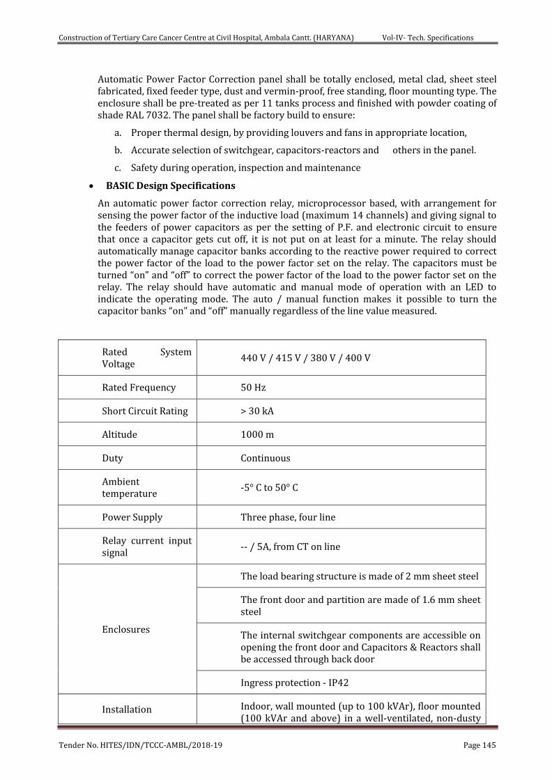
Construction of Tertiary Care Cancer Centre at Civil Hospital, Ambala Cantt. (HARYANA) Vol-IV- Tech. Specifications
Tender No. HITES/IDN/TCCC-AMBL/2018-19 Page 145
Automatic Power Factor Correction panel shall be totally enclosed, metal clad, sheet steel fabricated, fixed feeder type, dust and vermin-proof, free standing, floor mounting type. The enclosure shall be pre-treated as per 11 tanks process and finished with powder coating of shade RAL 7032. The panel shall be factory build to ensure:
a. Proper thermal design, by providing louvers and fans in appropriate location,
b. Accurate selection of switchgear, capacitors-reactors and others in the panel.
c. Safety during operation, inspection and maintenance
BASIC Design Specifications
An automatic power factor correction relay, microprocessor based, with arrangement for sensing the power factor of the inductive load (maximum 14 channels) and giving signal to the feeders of power capacitors as per the setting of P.F. and electronic circuit to ensure that once a capacitor gets cut off, it is not put on at least for a minute. The relay should automatically manage capacitor banks according to the reactive power required to correct the power factor of the load to the power factor set on the relay. The capacitors must be turned “on” and “off” to correct the power factor of the load to the power factor set on the relay. The relay should have automatic and manual mode of operation with an LED to indicate the operating mode. The auto / manual function makes it possible to turn the capacitor banks “on” and “off” manually regardless of the line value measured.
Rated System Voltage
440 V / 415 V / 380 V / 400 V
Rated Frequency 50 Hz
Short Circuit Rating > 30 kA
Altitude 1000 m
Duty Continuous
Ambient temperature
-5° C to 50° C
Power Supply Three phase, four line
Relay current input signal
-- / 5A, from CT on line
Enclosures
The load bearing structure is made of 2 mm sheet steel
The front door and partition are made of 1.6 mm sheet steel
The internal switchgear components are accessible on opening the front door and Capacitors & Reactors shall be accessed through back door
Ingress protection - IP42
Installation Indoor, wall mounted (up to 100 kVAr), floor mounted (100 kVAr and above) in a well-ventilated, non-dusty
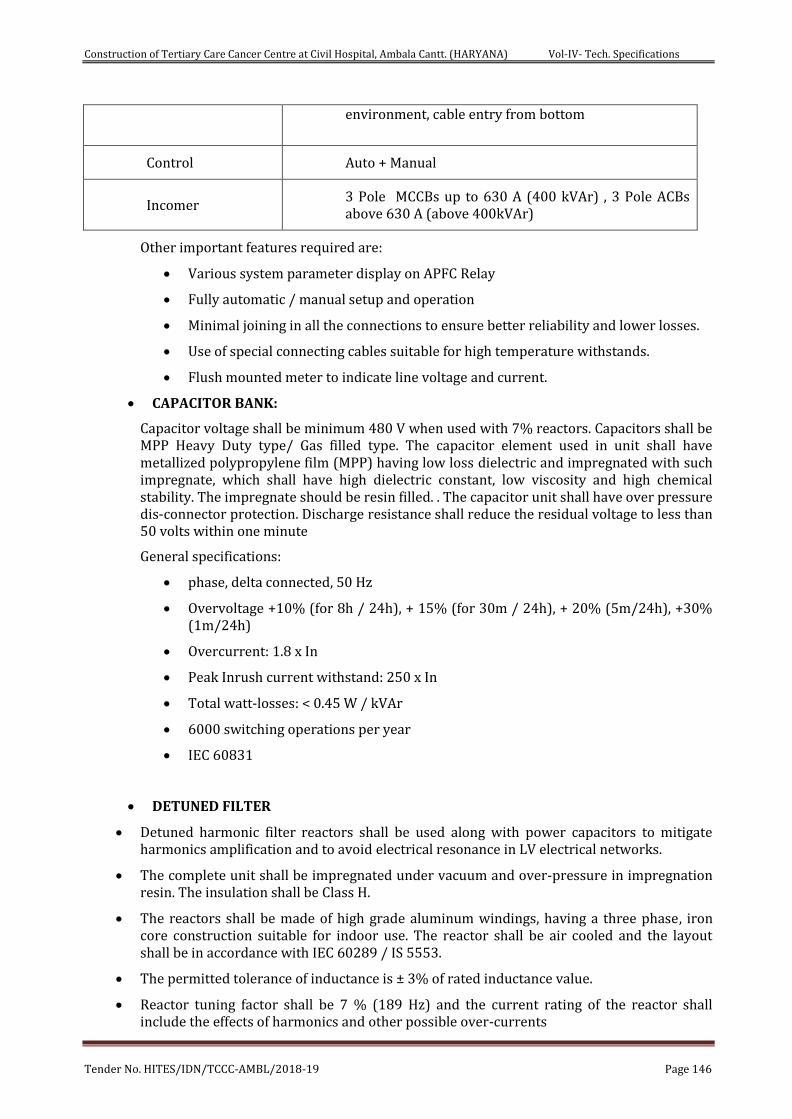
Construction of Tertiary Care Cancer Centre at Civil Hospital, Ambala Cantt. (HARYANA) Vol-IV- Tech. Specifications
Tender No. HITES/IDN/TCCC-AMBL/2018-19 Page 146
environment, cable entry from bottom
Control Auto + Manual
Incomer 3 Pole MCCBs up to 630 A (400 kVAr) , 3 Pole ACBs above 630 A (above 400kVAr)
Other important features required are:
Various system parameter display on APFC Relay
Fully automatic / manual setup and operation
Minimal joining in all the connections to ensure better reliability and lower losses.
Use of special connecting cables suitable for high temperature withstands.
Flush mounted meter to indicate line voltage and current.
CAPACITOR BANK:
Capacitor voltage shall be minimum 480 V when used with 7% reactors. Capacitors shall be MPP Heavy Duty type/ Gas filled type. The capacitor element used in unit shall have metallized polypropylene film (MPP) having low loss dielectric and impregnated with such impregnate, which shall have high dielectric constant, low viscosity and high chemical stability. The impregnate should be resin filled. . The capacitor unit shall have over pressure dis-connector protection. Discharge resistance shall reduce the residual voltage to less than 50 volts within one minute
General specifications:
phase, delta connected, 50 Hz
Overvoltage +10% (for 8h / 24h), + 15% (for 30m / 24h), + 20% (5m/24h), +30% (1m/24h)
Overcurrent: 1.8 x In
Peak Inrush current withstand: 250 x In
Total watt-losses: < 0.45 W / kVAr
6000 switching operations per year
IEC 60831
DETUNED FILTER
Detuned harmonic filter reactors shall be used along with power capacitors to mitigate harmonics amplification and to avoid electrical resonance in LV electrical networks.
The complete unit shall be impregnated under vacuum and over-pressure in impregnation resin. The insulation shall be Class H.
The reactors shall be made of high grade aluminum windings, having a three phase, iron core construction suitable for indoor use. The reactor shall be air cooled and the layout shall be in accordance with IEC 60289 / IS 5553.
The permitted tolerance of inductance is ± 3% of rated inductance value.
Reactor tuning factor shall be 7 % (189 Hz) and the current rating of the reactor shall include the effects of harmonics and other possible over-currents
Construction of Tertiary Care Cancer Centre at Civil Hospital, Ambala Cantt. (HARYANA) Vol-IV- Tech. Specifications
Tender No. HITES/IDN/TCCC-AMBL/2018-19 Page 147
The limit of linearity of inductance of the filter reactor is: 1.8*In with L=0.95*LN.
The reactor shall be fitted with a temperature sensitive micro-switch in the center coil (normally open) for connection to trip circuits in case of high operating temperatures.
Power loss in each reactor shall be less than 5 W/kVAr
Each reactor shall have routine test certificate for the above tests.
Contactor
All contactors shall be AC6B duty 3 pole air-break, magnetic, capacitor duty type. The rating of contactor shall be suitably assigned. The contactors shall be so chosen as to withstand inrush current due to parallel switching. Contactor should be with damping resistors to limit capacitor charging current
The individual capacitor bank/step shall be switched automatically / manually with selector switch as required using magnetic contactors suitable for switching capacitive currents. The contactor coil voltage shall be as specified.
The minimum life expectancy of the contactor shall be one million switching operations
Contactor should be with surge suppressor
Operation voltage up to 690V
Insulation voltage 1 kV
Rated impulse withstand up to 8 kV
APFC Controller
The APFC controller should be microprocessor based and should correct power factor with the help of contactors by switching the required no. capacitor banks
The controller should offer power factor correction without any need for manual intervention. The controllers should decide optimum configuration of capacitor banks in order to achieve desired power factor by taking into consideration the kVAr of each step, no of operations, total usage time, re-connection time of each step etc. Besides manual switching of capacitors should also be possible directly through the controller, The APFC controller should have the following basic features
Backlit LCD display with multiple parameters displayed at the same time
Auto step programmable
Capable of measuring VTHD and ITHD values at least up to 15th order
Automatic CT reversal sensing and correction
Should be 1A / 5A CT selectable.
Sensing shall be done at LT as well as HT side of the transformer
Display of average weekly power factor
Keypad lock feature to prevent operation by unauthorized persons
Alarms for under/over compensation, high VTHD/ITHD, over temperature, capacitor failure, capacitor over-current, over/under voltage
Individual capacitor’s ON/OFF status and capacitor failure indication
Temperature sensing feature with alarm in case of panel over heating
Construction of Tertiary Care Cancer Centre at Civil Hospital, Ambala Cantt. (HARYANA) Vol-IV- Tech. Specifications
Tender No. HITES/IDN/TCCC-AMBL/2018-19 Page 148
Should have RS485 communication protocol.
SWITCHGEAR & PROTECTION:
Suitable capacity duty contactor for each step shall be used and must be capable of capacitor switching duty. Busbars shall be suitably colour coded and must be mounted on appropriate insulator supports
Power cable used shall have superior mechanical, electrical and thermal properties. Internal wiring between main bus bars, contactor, capacitor etc shall be made with 1100 volt grade PVC insulated FRLS copper conductor of appropriate size by using suitable copper crimping terminal ends etc suitable bus links for input supply cable termination shall be provided.
Control circuit shall be duly protected by using suitable rating MCB. An emergency stop push button shall be provided to trip the entire system (22.5 mm dia, mushroom type, press to stop and turn to reset). 440 Volt caution board shall be provided on the panel.
TESTS AT MANUFACTURER’S WORKS:
All routine and type tests as per IS:2834 relevant to capacitor bank s as amended up to date shall be carried out at manufacturer’s works and test certificates to be submitted.
TEST AT SITE:
Insulation resistance with 500 V DC Meggar shall be carried out and test results should be recorded.
Residual voltage shall be measured after switching of the capacitors and the same shall not be more than 50 volts after one minute. Each discharge resister shall be tested for its working.
INSTALLATION:
Capacitor bank shall be installed at least 30 cm away from the walls on suitable frame work of welded construction. The earth terminals provided on the body of capacitor bank shall be bonded to main capacitor panel earth bus with 2 nos 8 SWG copper or 6 SWG GI earth wire.
Contractor shall also submit four sets of installation and maintenance manual.
L.T. CABLES & WIRE
a) Wires
The design manufacture, testing and supply of single core LEAD FREEFRLS PVC insulated 1.1 KV grade multi-stranded twisted wires under this specification shall comply with latest edition of following standards.
IS : 3961 Current rating for cables.
IS: 5831 PVC insulation and sheath of electric cables.
IS : 694 PVC insulated cables for working voltage upto and including 1100 volts.
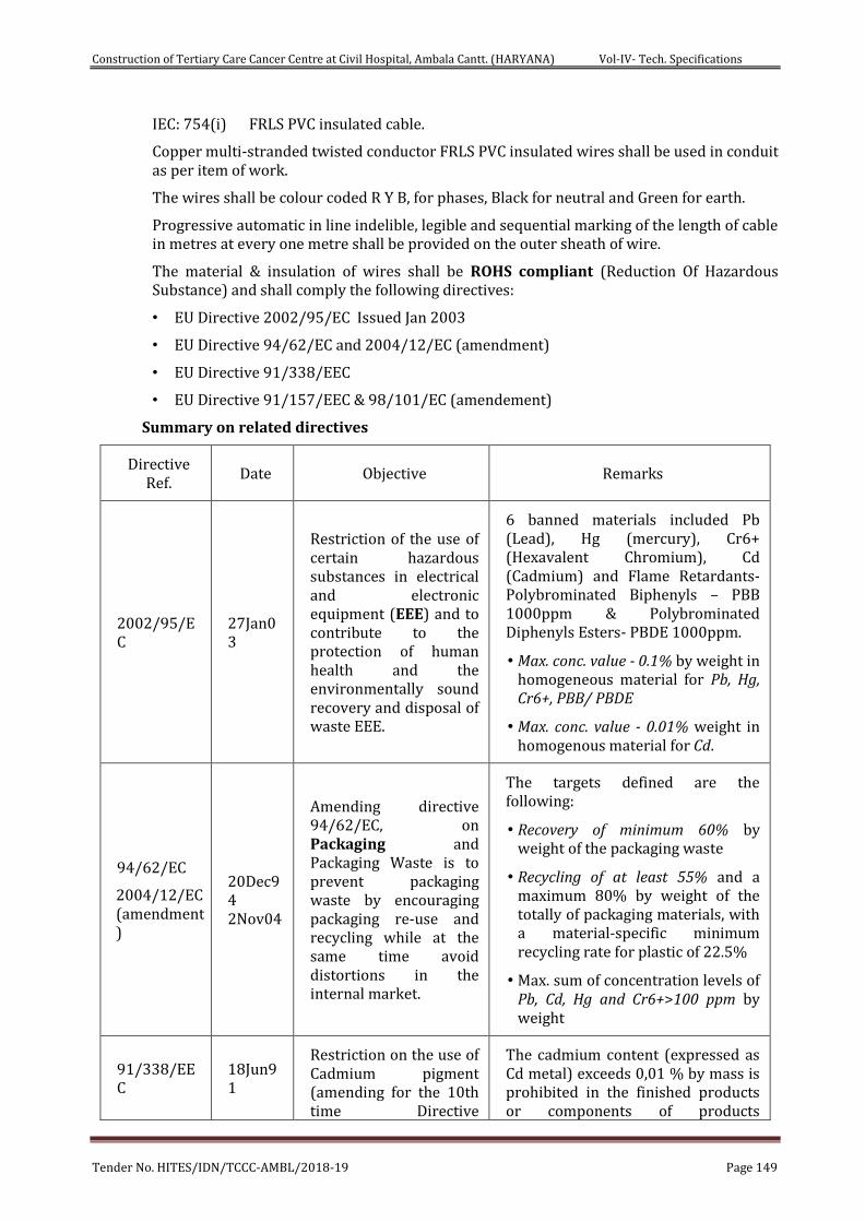
Construction of Tertiary Care Cancer Centre at Civil Hospital, Ambala Cantt. (HARYANA) Vol-IV- Tech. Specifications
Tender No. HITES/IDN/TCCC-AMBL/2018-19 Page 149
IEC: 754(i) FRLS PVC insulated cable.
Copper multi-stranded twisted conductor FRLS PVC insulated wires shall be used in conduit as per item of work.
The wires shall be colour coded R Y B, for phases, Black for neutral and Green for earth.
Progressive automatic in line indelible, legible and sequential marking of the length of cable in metres at every one metre shall be provided on the outer sheath of wire.
The material & insulation of wires shall be ROHS compliant (Reduction Of Hazardous Substance) and shall comply the following directives:
• EU Directive 2002/95/EC Issued Jan 2003
• EU Directive 94/62/EC and 2004/12/EC (amendment)
• EU Directive 91/338/EEC
• EU Directive 91/157/EEC & 98/101/EC (amendement)
Summary on related directives
Directive Ref.
Date Objective Remarks
2002/95/EC
27Jan03
Restriction of the use of certain hazardous substances in electrical and electronic equipment (EEE) and to contribute to the protection of human health and the environmentally sound recovery and disposal of waste EEE.
6 banned materials included Pb (Lead), Hg (mercury), Cr6+ (Hexavalent Chromium), Cd (Cadmium) and Flame Retardants- Polybrominated Biphenyls – PBB 1000ppm & Polybrominated Diphenyls Esters- PBDE 1000ppm.
• Max. conc. value - 0.1% by weight in homogeneous material for Pb, Hg, Cr6+, PBB/ PBDE
• Max. conc. value - 0.01% weight in homogenous material for Cd.
94/62/EC
2004/12/EC (amendment)
20Dec94 2Nov04
Amending directive 94/62/EC, on Packaging and Packaging Waste is to prevent packaging waste by encouraging packaging re-use and recycling while at the same time avoid distortions in the internal market.
The targets defined are the following:
• Recovery of minimum 60% by weight of the packaging waste
• Recycling of at least 55% and a maximum 80% by weight of the totally of packaging materials, with a material-specific minimum recycling rate for plastic of 22.5%
• Max. sum of concentration levels of Pb, Cd, Hg and Cr6+>100 ppm by weight
91/338/EEC
18Jun91
Restriction on the use of Cadmium pigment (amending for the 10th time Directive
The cadmium content (expressed as Cd metal) exceeds 0,01 % by mass is prohibited in the finished products or components of products
Construction of Tertiary Care Cancer Centre at Civil Hospital, Ambala Cantt. (HARYANA) Vol-IV- Tech. Specifications
Tender No. HITES/IDN/TCCC-AMBL/2018-19 Page 150
76/769/EEC) manufactured from polymers or copolymers of vinyl chloride and stabilized by substances.
b) Cables
The design, manufacture, testing and supply of the cable under this specification shall comply with latest edition of following standards:
IS: 8130 Conductors for insulated electric cables and flexible cords.
IS: 7098 XLPE insulation and sheath of electric cables.
IS: 3975 Mild steel wires, strips and tapes for armouring cables.
IS: 7098 Current rating of cables.
IS: 7098 XLPE insulated (heavy duty) electric cables for working voltage upto and including 1100 volts.
IS: 424-1475(F-3) Power cable-flammability test.
Specification for cross-linked polyethylene insulated XLPE sheathed cable for working voltage upto 1.1 KV.
Specification for XLPE insulated (heavy duty) electric cables for working voltages upto and including 1100 volts.
ASTM-D: 2863 Standard method for measuring the minimum oxygen concentration to support candle-like combustion of plastics (Oxygen Index).
ASTM-D: 2843 Standard test method for measuring the density of smoke from the burning or decomposition.
IEEE : 383 Standard for type of test Class-IE, Electric cables, feild splicers and connections for power generation station.
ASTME:662IEC:754(x) Standard test method for specific optical density of smoke generated by solid materials.
IS : 10418 Cable drums.
c) Technical Requirements:
i. The cables shall be suitable for laying in racks, ducts, trenches conduits and under-ground buried installation with uncontrolled back fill and chances of flooding by water.
ii. They shall be designed to withstand all mechanical, electrical and thermal stresses under steady state and transient operating condition.
iii. The aluminium/copper wires used for manufacturing the cables shall be true circular/sector in shape before stranding and shall be of uniformally good quality, free from defects. The conductor used in manufacture of the cable shall be of H2 grade.
iv. The cable should withstand 25 KA for 0.5 sec with insulation armour insulated at one end. Bidder shall furnish calculation in support of capability to withstand the earth fault currents. The current carrying capacity of armour and screen (as applicable) shall not be less than the earth fault current values and duration.
Construction of Tertiary Care Cancer Centre at Civil Hospital, Ambala Cantt. (HARYANA) Vol-IV- Tech. Specifications
Tender No. HITES/IDN/TCCC-AMBL/2018-19 Page 151
v. The fillers and inner sheath shall be of non-hygroscopic fire retardant materials and shall be suitable for the operating temperature of the cable. Filler and inner sheath shall not stick to insulation and outer sheath.
vi. Progressive automatic in line indelible, legible and sequential marking of the length of the cable in metres at every one metres shall be provided on the outer sheath of all cables and at every 5 metre ‘FRLS’ marking in case of ‘FRLS’ cables.
vii. Strip/Wire armouring following method (b) mentioned in IS: 3975 shall only be acceptable. For single core cable aluminium wire armouring shall be used.
viii. Allowable tolerance on the overall diameter of the cables shall be + 2mm.
ix. The normal current rating of all XLPE insulated cables shall be as per IS: 7098.
x. A distinct inner sheath shall be provided by pressure extrusion process for all multicore armoured and unarmoured cables as per IS: 5831.
xi. Outer sheath shall be provided by extrusion process as per IS: 5831
xii. The breaking load of armour joint shall not be less than 95% of that armour wire. Zinc rich paint shall be applied on armoured joint surface.
xiii. In plant repairs to the cables shall not be accepted.
xiv. All the cables shall be supplied in non-returnable drums as per IS: 10418.
d) In Case of FRLS Cables
i) The outer sheath of cables shall have an oxygen index of not less than 29 as per ASIMD: 2863.
ii) The maximum acid gas generation by weight as per IEC: 754 (i) shall not be more than 20% for outer sheath material of all cables. Bidder shall also guarantee the maximum theoretical acid gas generation with 20% by weight of outer sheath.
iii) The cables outer sheath shall meet the requirement of light transmission of 40% (minimum and shall be tested as per ISTMD: 2843). In case the test for light transmission is conducted as per ASTME: 662. The bidder shall furnish smoke density values as per this standard and shall co-relate the anticipated light transmission when tested as per ASTMD: 2843.
iv) The cable shall pass the fire resistance test as per SS: 42, 41, 475 (I) and flammability test as per EEE: 383.
e) Inspection:
All cables shall be inspected on receipt of the same at site and checked for any damage during transit.
f) Joint in Cables
The contractor shall take care that the cables received at site are distributed to various locations in such a manner as to ensure maximum utilisation and avoidance of cable jointing. Cable shall be rechecked before cutting in lengths, where the joints are unavoidable, and the location of such joints shall be got approved from the DGHS/HITES. The joints shall be done by qualified jointer strictly in accordance with manufacturer’s instruction/drawings.
g) Joint Boxes for Cables
The cable joint boxes shall be of appropriate size suitable for type of cable of particular voltage rating.
h) Jointing of Cables
Construction of Tertiary Care Cancer Centre at Civil Hospital, Ambala Cantt. (HARYANA) Vol-IV- Tech. Specifications
Tender No. HITES/IDN/TCCC-AMBL/2018-19 Page 152
All straight through joints shall be done in epoxy mould boxes with epoxy resins. Straight through joints shall not be permitted unless the length of run is in excess of cable drum.
End terminations of cables more than 1.1 KV grade shall be done with epoxy mould boxed and epoxy resin. Cable glands shall be 1.1KV grade double compression type and made to tin plated heavy-duty brass casting and machine finished. Glands shall be of robust construction capable of clamping cable and cable armour, firmly without injury of cable.
All washers and hardwares shall be made of brass tinned. Rubber components used in the glands shall be made of neoprene of tested quality.
Cable lugs shall be tinned copper/aluminium solderless crimping type conforming to IS: 8309 suitable for aluminium or copper conductor.
Crimping of terminals shall be done by using Corrosion inhabitory compound, with crimping tool.
Fire resistant paint has to be applied 1 Metre on either side of cable joint.
The contractor shall liaise fully with all other contractors to achieve an efficient and properly coordinated installation where equipment has to be re-positioned due to lack of site liaison; no extra cost shall be incurred by the HITES.
i) Testing of Cables
Cables shall be tested at factory as per requirement of IS: 7098 Part-I. The tests shall incorporate routine tests, type tests and acceptance tests. Prior to laying of cables, following tests shall be carried out:
i) Insulation test between phases and phase to earth for each length of cable before and after jointing.
On completion of cable laying work, the following test shall be conducted in the presence of Engineer-in-charge/HITES/ DGHS.
ii) Insulation resistance test (Sectional and overall) 1000/5000V depending upon the voltage grade of cable.
iii) Continuity resistance test.
iv) Sheathing continuity test.
v) Earth test.
j) Laying of Cable
The cable drum shall be placed on jacks before unwinding the cable. Great care shall be exercised in laying cables to avoid forming links. At all changes in directions in horizontal & vertical places, the cable shall be bent with a radius of bend not less than 8 times the diameter of cable.
The cable of 1.1KV grade shall be laid not less than 750mm below ground level in a 375mm wide trench (throughout), where more than one cable is to be laid in the same trench, the width of the trench shall be increased such that the interaxial spacing between the cables except where otherwise specified shall at least be 150mm minimum or as per site requirements or as approved by the Engineer-in-charge. Where single core cables are used in multiphase systems, the cables shall be installed in trefoil where possible.
In case the cables are laid in vertical formation due to unavoidable circumstance the depth per tier shall be increased by 200mm (minimum). Cable shall be laid in reasonably straight line, where a change in direction takes place a suitable cur-
Construction of Tertiary Care Cancer Centre at Civil Hospital, Ambala Cantt. (HARYANA) Vol-IV- Tech. Specifications
Tender No. HITES/IDN/TCCC-AMBL/2018-19 Page 153
vature shall be i.e. either 12 times the dia meter of the cable or the radius of the bend shall not be less than twice the diameter of the cable drum or whichever is less. Minimum 3-meter long loop shall be provided at both sides of every straight through joint & 3 meters at each end of cable or as directed at site.
Greater care shall be exercised in handling the cable in order to avoid forming ‘Kinks’. The cable drum shall in-verbally convey on wheels and the cable unrolled in right direction as indicated on the drum by the manufacturer. The cable shall be pulled over rollers in the trench steadily and uniformly without jerks and strains.
Cables laid in trenches in single tier formation, 10 cms. All around sand cushioning is provided below and above the cable before a protective cover is laid. For every additional vertical tier. The 30cm of sand cushion are provided over the initial tier. The cable shall be protected by 2nd class bricks of size not less than 230x115x75mm, stone tiles/RCC curved channel be placed on top of the sand breadth wise for the full length of the cable and where more than one cable is to be laid in the same trench the brick shall cover all cables and project at least 8 cms. Over the outer sides of the end cables.
Filling of trenches shall be done after the sand cushioning and laying of tilesor bricks are carried out to the satisfaction of the Engineer-in-charge (Refer drawing). Back fill for trenches shall be filled in layer not exceeding 150 mm. Each layer shall be properly rammed & consolidate before laying the next layer.
PVC pipe shall be provided for all road crossing. The size of the pipe shall be according to the cable and a minimum 100mm dia. pipe shall be provided. The pipe shall be laid in ground with special arrangement and shall be cement jointed and concreting with 1:5:10 shall be made as per relevant IS with latest amendment. Location of cables laid directly underground shall be indicated by cable marker at an interval of 30 meters & with change of direction. Aluminium strip cable tag of 20mm wide with engraved tag no. shall be provided at both ends of cable.
Where the cables are to be laid in ducts (pucca trenches) in side the building, they will have to be laid on MS rack/ on MS cable trays grouted in walls trenches. Cables sizing through floors shall be protected from mechanical damage by a steel channel to a height of one meter above the floor where cable pass through wall they shall be sleeved with PVC/steel conduit.
Where the cables are laid in open (in building) along walls, ceiling or above false ceiling, cable rack (ladder type) or cable tray shall be provided. The size of the cable tray or rack shall depend on the number of cables to pass over that rack. Cable tray/rack shall be properly supported through wall/ceiling according to the site conditions. Cable laid on tray & riser shall be neatly dressed &clamped at an interval of 1000 mm & 750mm for horizontal & vertical cable run respectively either side at each bend of cable. All power cables shall be clamped individually & control cables shall be clamped in groups of three or four cables. Clamps for multicore cables shall be fabricated of 25x3 GI flats. Single core power cable shall be laid in trefoil formation & clamped with trefoil clamps made of PVC/fibre glass.
Cable openings in wall/floor shall be sealed by the contractor suitably by hession tape & bitumen compound or by any other proven to prevent ingress of water.
After the cables are laid, these shall be tested as per IS and the results submitted to Engineer-in-charges/Engineer and in case the results found unsatisfactory, all the repairing/ replacing of cables will be done by the contractor free of charge.
k) Fire Seal System
Construction of Tertiary Care Cancer Centre at Civil Hospital, Ambala Cantt. (HARYANA) Vol-IV- Tech. Specifications
Tender No. HITES/IDN/TCCC-AMBL/2018-19 Page 154
i) All the floor/wall opening provided for cable crossing shall be sealed by fire seal system.
ii) The fire proof sealing system shall fully comply with the requirements of relevant IS/BS: 476 Part-B. The fireproof seal system shall have minimum one hour fire resistance rating.
iii) The fire proof seal system shall be physically, chemically, thermally stable and shall be mechanically secured to the masonary concrete members. The system shall be completely gas and smoke tight, antirodent and anti-termite.
iv) The material used in fireproof seal system shall be non-toxic and harmless to the working personnel.
v) Type of fireproof seal system shall be foaming type or flamemastic type compound or approved equivalent.
After laying and jointing work is completed, high voltage test should be applied to all cables to ensure that they have not been damaged during or after the laying operation and that there is not fault in the jointing.
Cables for use on low and medium voltage system (1.1KV grade cables) should withstand for 15 minutes a pressure of 3000V DC applied between conductors and also between each conductor and sheaths. In the absence of pressure testing facilities it is sufficient to test for one minute with a 1000V insulation tester In case the test results are unsatisfactory the cost of repairs and replacements and extra work of removal & laying will be made good by the contractor.
Cable shall be installed so that separation shown in the table below are observed.
HV Cable (11 KV/ 33 KV) - HV Cable (11 KV/ 33 KV) 50 mm
ELV & LV 230 V/433 V - ELV & LV cable 230 V/433 V Equal to the diameter of the bigger cable.
HV cables (11 KV/33 KV) - ELV & LV cables 230 V/433 V 300 mm
LV cables 433 V - Telephone/Instrument cable 350 mm
All cables - All hot pipe work 200 mm
l) Quality Assurance
Quality Assurance shall follow the requirements of DGHS/ HITES as applicable. Quality Assurance involvement will commence at enquiry and follow through to completion and acceptance thus ensuring total conformity to Purchaser’s requirements.
m) Deviations
Deviation from specification must be stated in writing at the quotation stage.
In absence of such a statement, it will be assumed that the requirements of the specifications are met without exception.
n) Spares for Commissioning Including Consumables
The manufacturer/tenderer shall also supply a complete list of commissioning spares and tools and consumables. The same shall be included in the bid price. No extra payment shall be made on account of non-availability of spares during commissioning.
CABLE TRAY
Construction of Tertiary Care Cancer Centre at Civil Hospital, Ambala Cantt. (HARYANA) Vol-IV- Tech. Specifications
Tender No. HITES/IDN/TCCC-AMBL/2018-19 Page 155
Ladder Type Cable Tray
Ladder type cable tray shall be fabricated out of double bended channel section longitudinal members with single bended channel section rungs of cross members welded to the base of the longitudinal members at a centre to centre spacing of 250 mm. The channel sections shall be supplied in convenient lengths and assembled at site to the desired lengths. These may be galvanized or painted to the desired lengths.
Perforated Type Cable Tray
i. The cable tray shall be fabricated out of slotted/perforated M.S. Sheet as channel section single or double bended. The channel section shall be supplied in convenient length and assembled at site to the desired lengths. All cable trays shall be hot dipped galvanized only as per relevant IS Codes.
ii. Typically, the dimensions, fabrication details etc. are shown in CPWD General Specification for Electrical Works - Part II -External, 1994 as amended up to date. The jointing between the sections shall be made with coupler plates of the same material and thickness as the channel section.
iii. Two coupler plates, each of minimum 200mm length, shall be bolted on each of the two sides of the channel section with 8mm dia round headed bolts, nuts and washers. In order to maintain proper earth continuity bond, the paint on the contact surfaces between the coupler plates and cable tray shall be scraped and removed before the installation.
iv. The maximum permissible uniformly distributed load for various sizes of cables trays and for different supported span are as per CPWD General Specification of Electrical Work Part II -1994. The sizes shall be specified considering the same.
v. The width of the cable tray shall be chosen so as to accommodate all the cable in one tier, plus 30 to 50% additional width for future expansion. This additional width shall be minimum 100mm. The overall width of one cable tray shall be limited to 800mm.
vi. Factory fabricated bends, reducers, tee/cross junctions, etc. shall be provided as per good engineering practice. (Details are typically shown in figure 3 of CPWD General Specification of Electrical Work Part II -1994) or as amended up to date. The radius of bend, junctions etc. shall not be less than the minimum permissible radius of bending of the largest size of cable to be carried by the cable tray.
vii. The cable tray shall be suspended from the ceiling slab with the help of 10mm dia MS rounds or 25 mm X 5 mm flats at specified spacing as per CPWD General Specification of Electrical Work Part II -1994 or as amended up to date. Flat type suspenders may be used for channels up to 450mm width bolted to cable trays. Round suspenders shall be threaded and bolted to the cable trays or to independent support angles 50mm x 50mm x 5mm at the bottom end as specified. These shall be grouted to the ceiling slab at the other end through an effective means, as approved by the PMC/Consultant to take the weight of the cable tray with the cables.
viii. The entire tray (except in the case of galvanized type) and the suspenders shall be painted with two coats of red oxide primer paint after removing the dirt and rust, and finished with two coats of spray paint of approved make synthetic enamel paint.
ix. The cable tray shall be bonded to the earth Terminal of the switch bonds at both ends.
x. The cable trays shall be measured on unit length basis, along the center line of the cable tray, including bends, reducers, tees, cross-joints, etc, and paid for accordingly.
Construction of Tertiary Care Cancer Centre at Civil Hospital, Ambala Cantt. (HARYANA) Vol-IV- Tech. Specifications
Tender No. HITES/IDN/TCCC-AMBL/2018-19 Page 156
SANDWICH BUS DUCTS/TRUNKING, RISING MAINS
Scope :
These specifications are intended for design, manufacturing, Supply, Installation, testing & commissioning of 3 Phase 3 Wire / 3 Phase 4 Wire (100% Neutral ) / 3 Phase 5 Wire Sandwich type Aluminum Busbar Trunking System.
System details :
The Busbar Trunking System shall be suitable for operational Voltage of 415V / 690V / 1000V with supply frequency of 50Hz, minimum insulation voltage of 1100V & impulse withstand voltage of 12 kV.
Standards :
The Busbar Trunking System shall be designed to comply in accordance with the following international standards,
IEC 61439 – Part 1 : Low voltage switchgear & controlgear assembly- General rules
IEC 61439 – Part 6 : Busbar Trunking Systems (busways)
IEC 60529 : Degree of protection
IS 8623 – Part 2 : Specification for Low Voltage Switchgear & Controlgear Assemblies
IS 1893 – Part 1 : Criteria for Earthquake Resistant Design of Structures
IEEE 693:2005 : High Seismic Qualification Level
Wherever required and specified, the Busbar Trunking System shall conform to Fire Rating of 600 deg C for 2 Hours.
Busbar Trunking System should also have Seismic Zone-5, Flame Propagation and Fire Resistance certification.
Manufacturer :
The manufacturer must have an established track record in design and manufacture of sandwichbusbar trunking system, and must have supplied busbar trunking systems for at least 20 years.
Design & Construction requirements :
General :
The Busbar Trunking System shall be of sandwich construction, non-ventilated and natural cooled design. It shall be possible to mount the Busbar Trunking System in any orientation without affecting the current rating.
Busbars :
The busbars should be made of high conductivity electrical grade Aluminum with conductivity >60%
Purity of Aluminum conductor should not be less than 99.6%
Aluminum busbars should be Tin plated at the joint area
Provision for mounting external earth strip to be provided on both side of busduct. 2 Nos. Copper earth strips of appropriate size shall be provided for the complete run of bus bars enclosure.
Construction of Tertiary Care Cancer Centre at Civil Hospital, Ambala Cantt. (HARYANA) Vol-IV- Tech. Specifications
Tender No. HITES/IDN/TCCC-AMBL/2018-19 Page 157
Insulation :
Each bus bar shall be individually insulated by means of Multi layer Class-F Insulation, Each layer shall have withstand breakdown voltage of minimum 6 kV.
The insulation material used shall be of minimum Class F (155 deg. C)
Insulation must be Halogen free & RoHS compliance
Housing :
The housing shall be made of minimum 1.6 mm electro-galvanized sheet steel, epoxy powder coated with RAL7032 shade.
Enclosure must be dust & vermin proof
IP rating of indoor busduct must be IP-54 / IP-55 & Outdoor busduct should be IP-65 / IP-66 with canopy.
Joints :
The joint design shall have inbuilt provision of absorbing expansion & contraction of 12mm per joint during operation.
The joint insulation must be of single piece moulded design of thermoset material for longer life and higher temperature withstand & better insulation property.
The joint construction must allow +/- 3mm adjustment at the time of installation, for ease of adjusting to site measurement variations.
The joint bolt must be insulated with a bolt insulator. The bolt insulator must be of molded one piece.
The joint design shall have inbuilt provision to prevent excessive insertion of busduct which can damage the bolt insulator.
The busbar ends shall not have holes or slots at the joints to avoid reduction in cross section area which will lead to temperature increase. The electrical continuity shall be through pressure plates, achieving a high contact area of joint cross section and expansion capability.
It shall be possible to install and remove the joints without disturbing the adjacent feeder section
Joint set should have insulators with temperature withstand capacity of class-F
Plug-in Unit / Tap off units :
Plug in boxes will be of draw out type. Contacts will be of silver plated copper and spring loaded. Earth connection will be the first to make and last to break during insertion and with drawl. Plug in boxes will be made from 1.6 mm CRCA sheet steel powder coated.
Each section of Bus Bar enclosure plug in ports spread at interval of approximately 600 mm for the insertion of plug in boxes.
Inside the plug in Boxes MCCB will be located as per requirements. The operating handle will be interlocked with plug in box cover so that MCCB can be operated only with the suitable cover in closed position. The plug in box will be interlocked with bus bar trunking so that it cannot be inserted or removed with the plug in box lid open. MCCB will be of 4 pole type. Short circuit breaking capacity of MCCB in Plug in Box should be same as that of bus trunking i.e. 50 KA.
Construction of Tertiary Care Cancer Centre at Civil Hospital, Ambala Cantt. (HARYANA) Vol-IV- Tech. Specifications
Tender No. HITES/IDN/TCCC-AMBL/2018-19 Page 158
When the MCCB in the Plug-in unit is in ‘ON’ position, the operator should not be able to open the door.
The design of plug-in units shall be such that, the PE conductor shall be of ‘First-Make’ ‘Last-Break’ type.
The Plug-in unit will be suitable for accommodating MCCBs or other accessories, as required. The Plug-in unit should allow the flexibility of accommodating different reputed MCCB makes, to be mutually agreed depending on the tender requirements.
Plug-in unit must achieve IP-54 protection
Plug-in units should be plug-in type up to 400A & Bolt-on Type from 630A
It should be possible to offer Bolt-on Type Tap-off Box for 100A & higher ratings to withstand vibration due to crane movement, heavy machines in industries
Routine & Type Tests :
The busduct shall be type tested at a reputed test laboratory (certified by ASTA or ERDA) for the tests as per IEC-61439 Part-1 (Low voltage switchgear & controlgear assembly- General rules) & Part 6 (Bus bar trunking systems & bus ways)
Short circuit testing of busduct should be for duration of 1 Sec. Neutral & Earth conductor should also be tested for 60% short circuit rating of phase conductor
Degree of ingress protection (IP rating) shall also be tested at any reputed independent laboratory as per IEC-60529
Dielectric test.
Busduct should be tested for minimum Seismic Zone-4 & High Seismic Qualification level as per IEEE:693
Installation:-
The Bus Section shall be joined together with flanges and tie bolts. Bus trunking shall be suspended at a uniform height as per site conditions above floor/Ground level with suitable MS suspenders and MS supports duly Hot dip Galvanised.
SECTION-IV-TECHNICAL SPECIFICATIONS FOR D.G.SETS
DIESEL GENERATOR SETS & ASSOCIATED WORK
SCOPE OF WORK:
This specification covers the design, manufacture, assembly, packing, dispatch, transportation, supply, erection, testing, commissioning, performance and guarantee testing of Diesel Gen-Sets with Acoustic Enclosure, complete in all respects with all equipment, fitting and accessories for efficient and trouble free operation as specified here under. All DG Sets shall be provided with Hospital Type Silencers.
Silent type Diesel Generator Set with suitable batteries, electrical panels, Radiator cooling system, exhaust system (as per the requirement), day tank fuel system, fuel piping etc. as per requirement.
The Scope of work shall also include labour, tools, tackles and plants, hardware and consumables, steel fabrication and items as prescribed below:
Diesel Engine and Alternator set complete with base frame and accessories.
DG Set shall be with PCCM / Synchronizing relay suitable for auto /manual / By pass arrangements.
Construction of Tertiary Care Cancer Centre at Civil Hospital, Ambala Cantt. (HARYANA) Vol-IV- Tech. Specifications
Tender No. HITES/IDN/TCCC-AMBL/2018-19 Page 159
Engine mounted engine control integral panel duly wired upto terminal box for engine safeties with sensors and protection for inter facing with PLC/Microprocessor based relay.
Fuel Oil system including day service oil tank, piping, valves, filters etc. from engine to service day oil tank.
Lube oil system with piping etc. (Pre-lube oil pump with controller if required).
For DG Sets upto & including 1010 KVA Rating: Radiator Cooled System without Cooling Towers.
For DG Sets above 1010 KVA Rating: Cooling system with Heat Exchanger, suitable rating Cooling Towers complete with makeup water tanks. GI B class Water Pipes of suitable size with valves & bends etc shall be provided between DG Sets & Cooling Towers.
Exhaust emission shall meet latest CPCB norms without catalytic converter or online scrubber and residential silencer, exhaust piping with mineral wool insulation and aluminum cladding as called for.
Steel fabricated structure/support/hanger including fixing, grouting and bolting etc.
Painting of steel work.
LT Termination Box shall be suitable for suitable size Sandwich busducts through flexible tinned copper busbars of suitable ratings.
Copper Control cabling between DG sets and respective LT Panels
Exhaust Gas Pipes MS C Class, 6 mm thick with all accessories and hardwares. Height of Exhaust pipes shall be provided as per relevant CPCB and CPWD norms.
MS Stack structure for supporting DG Exhaust Pipes duly painted with 2 coats of red-oxide primer & enamel paint of approved shade.
All DG Sets shall be provided adequate shading with polycarbonate sheets supported on MS structure duly painted.
Body & Neutral earthing of DG Sets complete with earth pits and earth strips/wire etc as per IS-3043.
All DG Sets shall be tested by an independent test laboratory ICAT (Manesar)/ ARAI, Pune to ascertain that DG Set will generate the net nominal full load at the stipulated ambient temperature conditions. Test Certificates for DG Sets shall be produced.
CODES & STANDARDS
The design, construction, manufacture, inspection, testing and performance shall comply with all the currently applicable statutes, safety codes, relevant Bureau of Indian Standard (BIS), British Standards (BS), International Electro Technical Commission (IEC) publication, standards amended up to date.
Some of the applicable standards are listed below :
(A) Generating Set
ISO 8528
Part – I Application, rating and performances. Part – II Engines Part – III A.C. Generator for generating set Part –IV Control Gear & Switch Gear
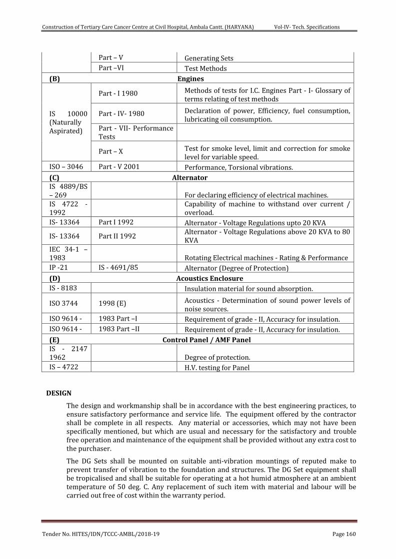
Construction of Tertiary Care Cancer Centre at Civil Hospital, Ambala Cantt. (HARYANA) Vol-IV- Tech. Specifications
Tender No. HITES/IDN/TCCC-AMBL/2018-19 Page 160
Part – V Generating Sets Part –VI Test Methods
(B) Engines
IS 10000 (Naturally Aspirated)
Part - I 1980 Methods of tests for I.C. Engines Part - I- Glossary of terms relating of test methods
Part - IV- 1980 Declaration of power, Efficiency, fuel consumption, lubricating oil consumption.
Part - VII- Performance Tests
Part – X Test for smoke level, limit and correction for smoke level for variable speed.
ISO – 3046 Part - V 2001 Performance, Torsional vibrations.
(C) Alternator IS 4889/BS – 269
For declaring efficiency of electrical machines.
IS 4722 -1992
Capability of machine to withstand over current / overload.
IS- 13364 Part I 1992 Alternator - Voltage Regulations upto 20 KVA
IS- 13364 Part II 1992 Alternator - Voltage Regulations above 20 KVA to 80 KVA
IEC 34-1 – 1983
Rotating Electrical machines - Rating & Performance
IP -21 IS - 4691/85 Alternator (Degree of Protection)
(D) Acoustics Enclosure IS - 8183 Insulation material for sound absorption.
ISO 3744 1998 (E) Acoustics - Determination of sound power levels of noise sources.
ISO 9614 - 1983 Part –I Requirement of grade - II, Accuracy for insulation. ISO 9614 - 1983 Part –II Requirement of grade - II, Accuracy for insulation.
(E) Control Panel / AMF Panel IS - 2147 1962
Degree of protection.
IS – 4722 H.V. testing for Panel
DESIGN
The design and workmanship shall be in accordance with the best engineering practices, to ensure satisfactory performance and service life. The equipment offered by the contractor shall be complete in all respects. Any material or accessories, which may not have been specifically mentioned, but which are usual and necessary for the satisfactory and trouble free operation and maintenance of the equipment shall be provided without any extra cost to the purchaser.
The DG Sets shall be mounted on suitable anti-vibration mountings of reputed make to prevent transfer of vibration to the foundation and structures. The DG Set equipment shall be tropicalised and shall be suitable for operating at a hot humid atmosphere at an ambient temperature of 50 deg. C. Any replacement of such item with material and labour will be carried out free of cost within the warranty period.
Construction of Tertiary Care Cancer Centre at Civil Hospital, Ambala Cantt. (HARYANA) Vol-IV- Tech. Specifications
Tender No. HITES/IDN/TCCC-AMBL/2018-19 Page 161
The engine alternation set shall be capable of working at ambient temperature between 0°C to 50°C and relative humidity upto 95%.
The operating capacity of each set shall be arrived at after considering a load with power factor of 0.8 lagging, and after taking into consideration suitable de-rating on account of above parameters of the station.
The engine/alternator set shall be capable of taking 10% over-load for a period of one hour during any 12 hours period, while operating continuously at full rated load.
Nominal output voltage of engine/alternator set shall be 415 volts 50 Hz AC Supply with manual adjustment at all conditions of load with coarse and fine controls with a range of ± 5%.
The frequency shall be maintained at 50 Hz ± 2% for the set. The output wave-form shall be sinusoidal at all load conditions.
The engine/alternator set shall be selected for a high degree of performance with over all low fuel consumption for the normal life of the alternator set.
The engine/alternator set shall meet the requirements of all linear & non-linear loads, but over-sizing of the alternator in order to meet the non-liner characteristics of loads in not envisaged.
The Engine shall be capable to minimum 60% bulk load of the rating during transfer of the load from NO Load position without tripping.
SYSTEM OPERATION
The set may be idle for a long time except for periodical test whenever there is a electrical supply failure, the set may required to run continuously for period even exceeding 24 hours.
SYSTEM FEATURE
The entire work shall confirm to Bureau of Indian Standards safety standards; British Standards, and CPWD specifications.
PERFORMANCE REQUIREMENT
The equipment shall be capable of delivering power continuously at the generator Terminal, a net output not less than the specified value at 0.8-0.95 p.f. excluding auxiliary power (shall be included over and above), when operating under the site ambient conditions described in this specification. Gen Set should be capable of taking 100 % step load & it should be able to take full load in less than 25 sec. from start. (The set shall be suitable for prime duty).
The design parameters of the generator and excitation system shall be chosen that the set is stable while running at any load between no – load and full load and also during starting of motors. It should also have synchronous speed control with load sensing governing system suitable for parallel running of D.G. sets.
Engine should be heavy duty four strokes, turbo charged after cooler ‘V’ construction/in line electric start. Engine should have minimum lube oil change period 500 Hrs. Bidders are required to offer the Duplex filter system for lube oil and fuel oil in case of non compliance.
The set shall have vibration limit less than 130 microns (as per BS:4999 Part – 142) & noise level shall be meet CPCB norms under all conditions of load. The set shall be dynamically balanced. The set shall be mounted directly on the inertia foundation or with foundation bolts etc. The efficient residential silencer shall be provided with or without catalytic converter on-line scrubber & the set shall meet EURO-II norms for D.G Sets, for the exhaust. Air inlet shall also be provided.
Construction of Tertiary Care Cancer Centre at Civil Hospital, Ambala Cantt. (HARYANA) Vol-IV- Tech. Specifications
Tender No. HITES/IDN/TCCC-AMBL/2018-19 Page 162
The engine shall be stationary, compression ignition, totally enclosed, water cooled, 4 stroke direct injection, cold battery starting, turbo charged and low temperature with after cooled Radiator Cooled 1500 RPM in accordance to BS 5514 and IS: 10002 complete with all accessories. The DG engine shall be suitable for quick start & should be able to pick up 100% load within optimum time.
The DG Engine & the batteries shall be designed to take up at least six starting attempts beyond which the system shall be protected by means of an over crank relay. Calculations for battery sizing and battery charger capacity shall be submitted for review of the consultants. The successful bidder will submit shop drawing of the equipments/accessories selected for this work for the approval.
SERVICE INTERVAL AND OPERATION
The set shall be capable of running at full load for not less than 500 hrs continuously. The change period both for the lube oil, lube oil filters shall be minimum 500 Hours of operations, in the event the change period for above consumables false short below the specified time period as above, bidders are required to quote for duplex type filters with oil make up systems.
DIESEL ENGINE - CONSTRUCTION
Material of construction of major parts shall be as under or as per manufacturer design.
M.S. base frame with anti-vibration mountings.
Crankcase – Aluminium alloys.
Crank shaft, connecting rods –Forged Alloy Steel.
Piston – AL alloy casting.
Piston rings – Alloy Steel.
Engine Block – Cast Iron
Cylinder Liner – Cast Iron
All other material of construction shall be as per relevant standard/code.
One common base frame shall be provided for mounting the engine and alternator complete with electric suspension between D.G set and foundation bolts, leveling lines etc. as required.
All externally mounted hardware shall be high tensile steel only.
The normal speed of the engine shall be 1500 RPM and the direction of rotation shall be clearly marked on the set.
The engine shall be fitted with an exhaust gas driven turbo charger of air / water cooled type complete with its own self contained lubricating system. The turbo-charger shall be positioned at the free end of the engine preferably.
The engine shall be fitted with a charge air inter cooler of the air/water type. Air from the turbo-charger compressor passes through the inter cooled and then to the engine manifold. The inter cooler shall be of tubular construction or as per manufacturer design with aluminum bronze tubes, mild sheet steel and cast iron water headers.
Fuel injection and valves shall not require frequent adjustment while in service.
All filters like fuel, lubrication oil, by pass etc shall be provided in the engine and shall be dry, paper element type.
Starting system shall be 24V DC comprising of SMF batteries (25 plates, 360 AH capacity or as recommended by OEM), Voltage Regulator and arrangement for initial charging of batteries.
Construction of Tertiary Care Cancer Centre at Civil Hospital, Ambala Cantt. (HARYANA) Vol-IV- Tech. Specifications
Tender No. HITES/IDN/TCCC-AMBL/2018-19 Page 163
Bed Plate
The bed plate shall be fabricated from M.S. channel. The welding shall be radio graphed, and the entire fabrication shall be stress relieved after welding. The bed plate shall have integral well ribbed diaphragms for supporting the main bearing housings.
Crank Case
The crank case shall be steel construction with heavy steel plates to form water compartments around the cylinder. To facilitate access for purpose of inspection, inspection ports shall be provided.
Lube-Oil Priming Pump
An A.C. motor driven intermittent operation lube-oil priming pump shall be provided. This shall also include necessary piping, fitting instruments etc. for lubrication system along with clock timers if required.
Crank Shaft
The crank shaft shall be made of high tensile strength steel forging, and shall have a suitable flange to which the flywheel shall be bolted.
The bearing journals and fillets shall be induction hardened; and fully balanced.
Main And Big End Bearings
The main and big end bearings shall be detachable shells of high grade bearing material, and shall be pre-finished.
Connecting Rods
The connecting rods shall be of high grade drop forged steel I - beam section, centre to centre length. The rods shall be rifle drilled for pressure lubrication of piston pin. The rod shall be tapered at piston pin end provided to reduce unit pressures. The piston pin of suitable diameter shall be full floating and made of tubular steel, and retained by a snap ring.
Cylinder Liners
The cylinder liners shall be replaceable wet liners, cast iron alloy, and provided with specially machined grooves in their bores to give an oil retaining surface. These liners shall be easily replaceable without re-boring the block.
Piston
The piston shall be made of forged aluminum alloy, cam ground and machined on outer surface. The piston shall be fitted with an oil scraper ring, and compression rings of hardened cast iron alloy. The piston shall be oil cooled.
Camshaft
The camshaft shall be of induction hardened steel alloy with gear drive, and one of this shall be provided for each block of cylinders.
Exhaust Manifold
The exhaust manifold shall be multi-branch, of insulated design utilizing Ni-resist casting.
Flywheel
The flywheel, which shall conform to requirements of NEMA/ASA/BS codes, shall be made of mild steel statically balanced after machining and shall have graduated markings around the periphery / markings for checking of the valves can also be located on the vibration damper. Barring slots shall be provided around the flywheel rim for hand-barring/ alternatively a suitable barring arrangement should be provided.
Construction of Tertiary Care Cancer Centre at Civil Hospital, Ambala Cantt. (HARYANA) Vol-IV- Tech. Specifications
Tender No. HITES/IDN/TCCC-AMBL/2018-19 Page 164
Governing System
The governor shall be Isochronous, electronic digital type with a steady state frequency variation of +/- .25%. The transient performance shall comply with ISO 8528-5, Class G3 requirements.
It should be possible to adjust the over speed settings on the governor by means of digital signals Manual adjustments for over speed trip settings are not preferred.
HEAT EXCHANGER
The DG Set should be equipped with a Heat Exchanger/ Radiator for suitable operation.
ALARMS/TRIP (AUDIO AND VISUAL)
The following Alarm/Trip indications shall be provided as minimum with first stage as pre alarm & second stage as trip:
High water temperature.
Low lube oil pressure.
Low fuel level.
Low coolant level.
Over crank
Over
OTHER AUXILIARY EQUIPMENT/SERVICES
These shall be complete include the following:-
Silencer
Exhaust Silencer shall be residential type to reduce the noise level. Values for Pressure drop across the silencers to be indicated by the vendor.
Cooling
The engine shall be water cooled heat exchanger type or radiator cooled depending on its capacity. DG Set shall be adequately designed for continuous operation on ambient conditions at 50 deg C.
INSTALLATION OF GENERATING SET
The engine and alternator shall be mounted on specially designed common MS base plate and frame of extremely rigid welded construction, so as to provide no deflection.
The engine/alternator set shall be installed over the Dunlop-make, S-type anti-vibration cushy base in order to isolate the transmission of vibrations to the floor or building structures.
The exhaust system shall be designed and installed in such a manner that it avoids excessive stresses on the exhaust manifold of turbocharger, washing spray or any other source.
The exhaust pipe shall pass through an oversized collar, filled with glass wool when crossing floor/wall.
All exposed metal parts shall be suitably painted to prohibit corrosion under the climatic conditions at site.
The installation of fuel piping, power distribution and control panels shall be carried out in accordance with the specification of respective items.
DAY SERVICE FUEL TANK
Construction of Tertiary Care Cancer Centre at Civil Hospital, Ambala Cantt. (HARYANA) Vol-IV- Tech. Specifications
Tender No. HITES/IDN/TCCC-AMBL/2018-19 Page 165
Day service fuel tank shall be made of 3 mm thick MS sheet of 990 litres capacity or as OEM standard capacacity for each set with all accessories such as oil level indicator, inlet pipe connection, outlet pipe connection, trough to collect spilt oil, air vent pipe with air filter, manhole with cover, low level and full level float valve arrangements with all fittings, interconnections between tanks and engine. The tank shall be provided with suitable calibration scale. The Fuel to be used for trials and acceptance tests shall be high speed diesel. First fill of 990 litres HSD per DG set required coolant and lube oil is included in the scope of this contract at no. extra cost.
FOUNDATION
Foundation shall be casted as per the recommendations of the manufacturer in consultation with the Supplier and as per the requirements of the site. The successful bidder shall submit detailed foundation drawings for approval from client.
PAINTING
The Contractor shall paint all exposed metal parts and equipment supplied by him. All sheet metal work shall undergo a process of phosphating, passivating and then sprayed with high corrosion resistant primer. The finishing treatment shall be of two coats of synthetic enamel paint of approved color. All piping shall be color coded.
ALTERNATOR
The alternator shall be brushless synchronous and suitable for 3 phase 415 Volts, 4 wire, 50 Hz, 0.8 PF, 1500 RPM.
The alternator shall be suitable for coupling directly to the diesel engine It shall be Drip proof, screen protected as per IP-23. The alternator shall be single bearing type & self ventilating. The alternators shall be continuously rated and shall have class ‘H’ insulation with a temperature rise restricted to that of class F designed and built to withstand tropical conditions. It shall generally conform to BS: 5000 (Part - 99) / standards listed above. The alternator shall be suitable for sustaining a 10% overload for 1 hour in any 12 hour period without injury. The terminal arrangement for alternator shall be suitable for Cable connections of adequate size to deliver the full load of the alternator.
The alternator shall also have a solid state type digital voltage regulator (D.V.R.) suitable for single running with control limits of 1% from no load to full load under normal load changes. It shall be of static type and complete with cross current compensation. The regulator shall be provided with voltage adjusting potentiometer, and shall be complete with all alarm contacts, internal wiring, etc.
The Engine and Alternator shall be direct coupled and mounted on a common rigid fabricated steel base frame with suitable vibration isolation system.
EXCITOR
Self excited, self regulated and providing alternator output regulation at plus or minus 0.25%. The alternator shall be provided with a pilot-excited, permanent magnet-excited generator (PMG) for superior short circuit capabilities. Bidders to specify sustained short circuit current capabilities for up to 10 seconds.
The alternator shall be provided with sealed Barings to give minimum service life of 40,000 Hours. The Bidders to specify the maximum rating of the motor that can be started direct on line without any base load, with 50% base load, restricting the Voltage depth to 20%.
INSTRUMENTATION
Instrumentation shall be provided and mounted on the Generator Set to monitor the following:
Engine Speed
Construction of Tertiary Care Cancer Centre at Civil Hospital, Ambala Cantt. (HARYANA) Vol-IV- Tech. Specifications
Tender No. HITES/IDN/TCCC-AMBL/2018-19 Page 166
Oil Pressure
Oil Temperature
Water Temperature.
A Gauge Board shall be provided with all the indicators grouped together. The generator shall be provided with a microprocessor-based controller with a facility for remote start, remote annunciation , auto / manual synchronizing and remote communication capability. It should be possible to monitor the parameters of the engine and the alternator and display the status of the faults on the DG set if any and generate a complete report on the PC individually. The following minimum monitoring & protection is required for the alternators.
Alternator Monitoring
Current. (I1, I2, I3)
Frequency
Voltage (L-L & L-N)
KVA
KVAR
Power Factor
Percentage alternator duty heavily i.e. actual load / KW rating.
The Generator shall be protected against the following electrical faults:
Overload and short circuit
Ground fault
Over current
Over frequency
Under frequency
Under Voltage
Over Voltage
Locked Rotor
Reverse power protection.
It should be possible to read the data i.e. Parameters and Shutdown status locally on the D.G Set. All the above Parameters should be displayed on The Local Control Panel through appropriate meters and status on faults should be indicated through a facia annunciator. It should be possible to display all the functions as above on a personal computer.
EXHAUST SILENCER PIPING
Exhaust Piping: The exhaust silencer piping system shall be of heavy duty MS, Class-C pipes, 6 mm thick. The runs forming part of factory assembly on the engine fl exible connections up to exhaust silencer shall be exclusive of exhaust piping item. The work include necessary cladding of exhaust pipe work using 50 mm thick Loosely bound resin (LBR) mattress/ mineral wool/ Rockwool, density not less than 120 kg/m3 and aluminium cladding (0.6 mm thick) for the complete portion. The exhaust pipe work includes necessary supports, foundation etc. to avoid any load & stress on turbo charger / exhaust
Construction of Tertiary Care Cancer Centre at Civil Hospital, Ambala Cantt. (HARYANA) Vol-IV- Tech. Specifications
Tender No. HITES/IDN/TCCC-AMBL/2018-19 Page 167
piping. The exhaust pipe shall be run along the existing wall of the building duly clamped/supported on independent structure for which, the design and Drawing for such structure shall be got approved from the Engineer-in-charge.
Exhaust system should create minimum back pressure.
Number of bends should be kept minimum and smooth bends should be used to minimize back pressure.
Pipe sleeve of larger dia. should be used while passing the pipe through concrete wall & gap should be filled with felt lining.
Exhaust piping inside the Acoustic Enclosure/ Genset room should be lagged with asbestos rope along with aluminium sheet cladding / insulated to avoid heat input to the room.
Exhaust flexible shall have it’s free length when it is installed. For bigger engines, 2 flexible bellows can be used.
For engines up to 500 KVA, only one bellow is required. However, if exhaust pipe length is more than 7 m then additional bellow/ provision for expansion should be provided.
‘C’ Class MS pipes and long bend/elbows should be used.
The exhaust outlet should be in the direction of prevailing winds and should not allow exhaust gases to enter air inlet/ windows etc.
When tail end is horizontal, 45 Degree downward cut should be given at the end of the pipe to avoid rain water entry into exhaust piping.
When tail end is vertical, there should be rain trap to avoid rain water entry. If rain cap is used, the distance between exhaust pipe and rain cap should be higher than diameter of pipe. Horizontal run of exhaust piping should slope downwards away from engine to the condensate trap. Silencer should be installed with drain plug at bottom.
TESTS AT MANUFACTURER'S WORK
The following tests shall be performed at manufacture’s works prior to packing and dispatch to site.
On DG Set
Maximum power load capacity.
Maximum motor starting capacity
Endurance test.
Fuel consumption at full load, 50% load, 75% load and 25% load.
Engine - Alternator cooling air flow
Load acceptance Test
On the Alternator
High voltage tests on stator and rotor windings.
Insulation resistance of stator and rotor windings.
Temperature rise test.
Measurement of resistance of stator and rotor windings.
Measurement of losses.
Mechanical balance.
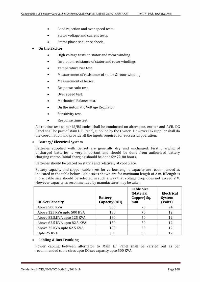
Construction of Tertiary Care Cancer Centre at Civil Hospital, Ambala Cantt. (HARYANA) Vol-IV- Tech. Specifications
Tender No. HITES/IDN/TCCC-AMBL/2018-19 Page 168
Load rejection and over speed tests.
Stator voltage and current tests.
Stator phase sequence check.
On the Excitor
High voltage tests on stator and rotor winding.
Insulation resistance of stator and rotor windings.
Temperature rise test.
Measurement of resistance of stator & rotor winding
Measurement of losses.
Response ratio test.
Over speed test.
Mechanical Balance test.
On the Automatic Voltage Regulator
Sensitivity test.
Response time test
All routine test as per IS/BS codes shall be conducted on alternator, exciter and AVR. DG Panel shall be part of Main L.T. Panel, supplied by the Owner. However DG supplier shall do the coordination and provide all the inputs required for successful operation.
Battery/ Electrical System
Batteries supplied with Genset are generally dry and uncharged. First charging of uncharged batteries is very important and should be done from authorized battery charging centre. Initial charging should be done for 72-80 hours.
Batteries should be placed on stands and relatively at cool place.
Battery capacity and copper cable sizes for various engine capacity are recommended as indicated in the table below. Cable sizes shown are for maximum length of 2 m. If length is more, cable size should be selected in such a way that voltage drop does not exceed 2 V. However capacity as recommended by manufacturer may be taken.
DG Set Capacity Battery Capacity (AH)
Cable Size (Material Copper) Sq. mm
Electrical System (Volts)
Above 500 KVA 360 70 24
Above 125 KVA upto 500 KVA 180 70 12
Above 82.5.KVA upto 125 KVA 180 50 12
Above 62.5 KVA upto 82.5 KVA 150 50 12
Above 25 KVA upto 62.5 KVA 120 50 12
Upto 25 KVA 88 35 12
Cabling & Bus Trunking
Power cabling between alternator to Main LT Panel shall be carried out as per recommended cable sizes upto DG set capacity upto 500 KVA.
Construction of Tertiary Care Cancer Centre at Civil Hospital, Ambala Cantt. (HARYANA) Vol-IV- Tech. Specifications
Tender No. HITES/IDN/TCCC-AMBL/2018-19 Page 169
As far as possible, for DG Set of capacity 500 KVA & above connection between alternator to Main LT Panel shall be through Sandwich bus trunking. For exposed/ outdoor bus trunking protection requirement should be IP-66.
While terminating cables, avoid any tension on the bolts/ busbars (if cable is specified). While terminating R, Y& B phase notations should be maintained in the alternator and LT Panel for easy maintenance. Crimped cables should be connected to alternator and control panel through cable glands.
Multi-core copper flexible stranded cable of 2.5 Sqmm size should be used for inter connecting the engine controls with the switchgear and other equipments. External wirings, when provided for remote voltage / excitation monitoring/ droop CT etc. shall be screened sheathed type.
Alternator Termination Links
For proper terminations between links and Cables/switchgear terminals, the contact area must be adequate. The following situations should also be avoided as they lead to creation of heat sources at the point of termination:
(i) Point contact arising out of improper position of links with switchgear terminals
(ii) Gaps between busbars / links and terminals being remedied by connecting bolt/stud In such cases the bolt will carry the load current. Normally these bolts / studs are made of MS and hence are not designed to carry currents.
Adequate clearance between busbars / links at terminals should be maintained (IS 4232 may be referred to for guidelines). Improper termination will lead to local heat generation which may lead to failure.
INSPECTION AND TESTING AT SITE
All pre-commissioning and commissioning test and checks shall be carried out at site. The Contractor shall be required to produce manufacturer's test certificate for the particular batch of materials supplied to him by the manufacturers. The test carried out shall be as per the relevant standards. For examination and testing of materials and the works at site, the Contractor shall provide necessary testing and gauging equipment as required. All such testing and gauging equipment shall be tested for calibration at any approved laboratory as required by the Engineer In Charge. The Contractor shall give notice well in advance to the Engineer In Charge before commencement of any site testing. All materials like consumable stores, fuel oil grease, lubricating oil etc. required for the trails shall be arranged by the contractor. The Contractor shall make all necessary hook-ups to carry out tests at site and shall furnish necessary fuel. The complete installation should be initially started and checked out for operational compliance by manufacturer's representative.
TRIALS (AT SITE):-
Preliminary Trials
After completion of erection of generating sets and before carrying out main trials, preliminary site trials shall be conducted in the presence of the Engineer In Charge. Such trials shall include the checking and adjustments of all instrument relays, timers, interlocks and meters. Insulation resistance of stator, rotor and exciter windings shall be checked and reading recorded. A check shall be made for the satisfactory working of all auxiliary motors and their starting accessories supplied with the set. Diesel & lubricating oils for establishing performance at site shall be arranged by the contractor without any extra cost.
Main Trials
The main trials shall include over 8 hours continuous run at available load. D.G. Panel shall be tested for automatic operation by injecting proper current and voltage by a separate
Construction of Tertiary Care Cancer Centre at Civil Hospital, Ambala Cantt. (HARYANA) Vol-IV- Tech. Specifications
Tender No. HITES/IDN/TCCC-AMBL/2018-19 Page 170
source. The satisfactory working of automatic operation shall be tested and necessary adjustments shall be done for relays in the presence of the Engineer In Charge and the results shall be recorded in the test sheet at 30 minutes intervals. Alternator efficiencies as determined in works test shall be used as the basis of calculation for fuel consumption rate. A tolerance of 3% shall be allowed on the fuel oil consumption to cover possible errors in measurement.
Tests providing the satisfactory performance of all safety and operating controls shall be carried out. Governor trials shall be carried out as laid down in ISO: 3046. Alternator insulation resistance and commutation check shall be as per ISO: 3046. Starting time of sets shall be tested at least five times after sufficient time intervals to allow for cold start. On completion of tests, inspection doors shall be removed and running gears inspected and alignment checked.
Any further reasonable trial as suggested by the Engineer In Charge shall be carried out with no extra charges. All instruments, materials and labour required for carrying out the trials shall be provided by the Contractor. Test sheets of trials shall be forwarded in quadruplicate to Engineer In Charge.
TEST WITNESS
Tests shall be performed in the presence of Engineer In Charge. The contractor shall give at least thirty (30) days advance notice of the date when the tests are proposed to be carried out.
EXHAUST SILENCER PIPING
The Exhaust piping system for the DG set shall be as per CPWD Specifiactaions meeting the requirements of CPCB Norms. The exhaust silencer piping system shall be of heavy duty MS pipes confirming to class B. Suitable length of flexible piping shall be used for connecting the exhaust piping to the engine as per the recommendation of the manufacturer. MS screws flanges and bends shall be used as per site requirements. Exhaust pipe inside the building shall be logged with heat resistive glass wool of 48 kg / meter cube and then cladded with Al. foil all along the pipe.
Exhaust Stack Height- In order to dispose exhaust above building height, minimum exhaust stack height should be as follows:-
a. For DG Sets up to 1000 KVA - H = h+0.2√KVA
where H = Height of Exhaust stack, h = Height of building
b. For DG set above 1000 KVA - 30 M or 3M above the building height, whichever is higher
The Exhaust Piping stack shall be supported by suitable MS steel structure with twin aviation light at the top of the exhaust piping.
Synchronization System
The synchronization panel shall be complete in all respects for auto operation of D.G. Sets. The minimum requirement for D.G. set operation shall be as detailed below, however, the vendor shall indicate in details the additional features and facilities being offered by them.
The parallel operation of D.G. set in Synchronization mode shall be completely through Power Control Center Module (PCCM). The PCCM shall be mounted on DG SETs outside the Building (the supplying and fixing of the PCCM is in the scope of Supplying and fixing of DG vendor Set). The PLC for the further operation shall be mounted on the Synchronizing panel with SLC 5/03 processor, kw transducer &
Construction of Tertiary Care Cancer Centre at Civil Hospital, Ambala Cantt. (HARYANA) Vol-IV- Tech. Specifications
Tender No. HITES/IDN/TCCC-AMBL/2018-19 Page 171
suitable input /out put card,8 channel analog card Power Monitors – IV . The wiring between the DG Sets, PCCM and Synchronizing Panel is included in the scope.
During the parallel operation, the system take care of the load sharing i.e. active and reactive both for all the D.G. sets. and issue soft commands for voltage / frequency raise / lower,
Depending upon the load requirements, the system shall start / stop the D.G. sets.
Monitoring & logging of the electrical data and events through existing P C. This will be achieved by using microprocessor based PC controller or equivalent networking kits & required hardware like GCM, modlon convertor ,communication cable.
Alarms and necessary remedial commands for D.G. and electrical system fault.
D.G synchronizing panels . Local Control and Manual Synchronization
(Common for all D.G. Sets Part of the Synchronizing Panel)
The minimum equipment shall be as follows:
DG selector switch
PLC / manual selector switch
Double scale voltmeter
Double scale frequency meter
Synchronoscope
Check synchronization relay
Synchronization lamps
Solo parallel selector switch
Manual synchronization circuit “ON”/”OFF” selector switch
Push buttons & indicating lamps
Control PT
Mimic
The following components shall be provided for each DG Set :
a. Breaker control Switch except for DG Incomer.
b. Automatic battery charger having inbuilt Trickle /boost facility selector switch for battery charger
c. DC digital Ammeter and Voltmeter selector switch
d. Auto/Manual selector switch for priming pump
e. Breaker control switch (only for one number bus-coupler required)
f. Indicating lamps (LED type) for following:
g. R1Y1B, phase indication
h. D.G breaker “ON”/”OFF” spring charged
i. Neutral contactor “ON” /”OFF”
j. Engine running
k. Battery charger “ON”
l. Control supply healthy
Construction of Tertiary Care Cancer Centre at Civil Hospital, Ambala Cantt. (HARYANA) Vol-IV- Tech. Specifications
Tender No. HITES/IDN/TCCC-AMBL/2018-19 Page 172
m. Priming pump “ON” /”OFF”
n. Speed raise /low joystick
o. Voltage raise / low joystick
p. 12 window annunciator with alarm Accept/Test/Reset push buttons, Hooter.
q. Temperature Scanners for RTD and BTD
r. Beacon light
s. Hour meter
t 5 Nos. Under voltage relay for mains feeder “
t. 5 Nos. Over Voltage relay for mains feeder “
u. Stand by Earth fault relay ‘’
v. Reverse power relay (reactive) “
w. Trip circuit supervision relay “
x. Master trip relay “
y. 5 H.P, DOL starter for oil priming pumps for D G Set
z. Power factor meter ( Analog)
aa. Frequency meter (Digital)
bb. Ammeter (Digital)
cc. Voltmeter (Digital)
dd. KW and KVA meter (Digital)
ee. Kwh meter (Digital)
ff. D.C. Ammeter (digital)
gg. D.C. Voltmeter (digital)
hh. Breaker Control Switch for bus coupler
ii. Battery Charger on / off switch with boost and trickle charger facility
jj. Trickle / booster charger selector, switch
kk. Push buttons (lot)
ll. P. T
mm. Aux. Contactor (lot)
nn. transducers
Automatic Generator Sequencing
a) Automatically start & stop gen sets based on plant load or bus on process demand.
b) Configurable plant bus demand start / stop levels and timers.
c) On line engine priority sequence configurability from any synch. Unit or PC to equalize run time of all DG Sets.
SYNCHRONISING PANEL
The technical specification and details of the microprocessor based PLC controller for the DG set synchronizing and load sharing shall be as follows:
Construction of Tertiary Care Cancer Centre at Civil Hospital, Ambala Cantt. (HARYANA) Vol-IV- Tech. Specifications
Tender No. HITES/IDN/TCCC-AMBL/2018-19 Page 173
The microprocessor based PLC panel shall be suitable for use with AVR and electronic speed governor to protect and monitor DG sets.
Double Frequency Meter and Double Voltmeter shall be provided in synchronizing panel.
Synchrony check relay also shall be provided.
The PLC shall be provided with following features and audible alarm:
o Engine pre glow control
o Fuel solenoid control
o Engine starter control
o KVA controlled cool-down timer
o Speed monitoring
o Over speed protection
o Oil pressure monitoring, alarm and shutdown of the engine.
o Water temperature monitoring, alarm and shutdown of the engine
o Battery voltage monitoring
o Over speed monitoring and alarm.
o 3 attempt start failure alarm
o Under/Over Frequency
o Reserve Power (Inverse time delay)
o Loss of excitation
o Over current (inverse time delay)
o Loss of utility power detection
o Load surge
o Current unbalance
o Voltage unbalance
o Mains Protection (vector shift, df/dt ROCOl)
o True RMS power calculations accurate control
o Configurable loading/unloading ramp rates
o Isochronous load sharing of up to 4 units using percentage based load sharing
o Base load control for optimum fuel efficiency
o Import export control using a watt transducer
o Soft utility transfer function
o Digital signal processing to eliminate harmonic issues
o Adjustable phase window, Voltage and dwell time
o Safe dead bus closing logic internal to the control
o Synchronization across generator and mains breakers
o Multiple short re-closing with adjustable time delay
Construction of Tertiary Care Cancer Centre at Civil Hospital, Ambala Cantt. (HARYANA) Vol-IV- Tech. Specifications
Tender No. HITES/IDN/TCCC-AMBL/2018-19 Page 174
o Manual voltage and speed adjusts for manual synchronizing
o VAR sharing on isolated busses using percentage based reactive load sharing
o Power factor or VAR control when base loaded
o Externally adjustable VAR or PF set point levels.
o The DG set shall start and stop automatically based on plant bus demand.
The PLC system shall be provided with built in relays for protection of the following:
o Reverse Power
o Reverse KVAR
o Over current
o Under and over voltage
o Under and over frequency
o Synchronization check and earth fault relay.
The PLC system shall be suitable for load sharing by sensing active and reactive power.
The PLC system shall comprises of the following:
o Main processor unit
o Power module for power supply to the processor and the system
o Power monitor to monitor voltage, KVA, KVAR, KW, KWH, KVAH, KVARH.
o 16/32 channel Digital input module
o 16/32 channel Digital output module
o EEPROM for main processor unit
o Computer to PLC communication card with necessary cables.
o Window based operator interface Software Package
o Mounting chassis for the equipment
The microprocessor based main processor of the system shall be suitable for 128 digital I/P and 128 O/P and comprises of the following:
The main processor unit shall be suitable for operation on 24 Volts DC with integrated memory. The integrated Ram memory shall be 20 K Words for program, data and constants plus data memory and flash EPROM of 16 K works for backup application program, communication card and real time clock. 4 Nos. discrete combination module (Input/output Module) shall be provided and the same shall be suitable for operation on 24 volts DC system. Combination module shall be with 16/32 inputs and 16/32 output channels as per the actual requirement.
o 1 No. 2 slot extension rack
o 1 No. Ram back up battery unit
o 8/4 Nos. digital input module
o 8/4 Nos. digital output module
Construction of Tertiary Care Cancer Centre at Civil Hospital, Ambala Cantt. (HARYANA) Vol-IV- Tech. Specifications
Tender No. HITES/IDN/TCCC-AMBL/2018-19 Page 175
The CPU display unit shall be suitable for 4 lines of 40 characters. The display shall be with back lit LCD. Clarity shall be not less than 5 x 7 pixels. The height of the characters shall be not less than 5 mm. The data entry shall be with the help of 24 function keys. In addition to this there shall be 10 service keys and 12 alphanumeric keys. The system shall be provided with RS 232 communication port.
OPERATION AND COMMUNICATION
The PLC shall monitor the bus bar load continuously. In event of mains failure the PLC shall give signal to select and start the generator, which is closer to the load sensed during the last 60 seconds. In case the load at the time of main failure is more than the highest rating DG set, the PLC shall give command to start 2 Nos. DG sets to suit the load, synchronize the sets and give command to close the breaker on the main LV panel.
If load starts reducing the PLC shall give command to turn off the DG sets through cool down timer. On restoration of main power supply, the PLC shall check the voltage and frequency and if they are stabilized and within the permissible tolerances, the PLC shall give command to shut down the DG sets through cool down timer.
The control and monitoring of the cooling tower and fan and feed pump shall be done through PLC control system. Necessary control wiring between cooling tower, pumps and PLC panel shall be carried out within the scope of work.
SYNCHRONIZING MODULE
The synchronizing module shall be a microprocessor based intelligent unit, which shall monitor the electrical parameters and shall able to communication with the PLC control unit in the process of synchronizing and load management. The system shall be suitable for dynamic synchronization. The synchronizing module shall be suitable for programming and set the preferred difference between DG set and bus bar.
The synchronization module shall monitor and fulfill the following conditions before the system synchronizes the DG set to mains.
Feed bank signal from the DG breaker on main LV panel that the breaker is in open condition.
o Bus bar voltage is present
o Generator voltage is present
The frequency regulator in the system shall start when the generator voltage and the bus bas voltage is over 50% of normal voltage. The voltage regulator in the system shall start when the frequency is within 90% of the normal system frequency.
The system shall close the breaker on the power panel without carrying out synchronization when all the below mentioned conditions are fulfilled.
Feedback signal from the DG breaker on main LV panel that the breaker is in closed condition.
o Bus bar voltage is present
o Generator voltage is present
The synchronizing module shall transmit all monitored electrical parameters to the PLC unit and the PLC unit shall start controlling the synchronization of the DG sets and its load management. The data logging, monitoring shall also be through a PC based BMS station.
SHOCK TREATMENT CHART
Construction of Tertiary Care Cancer Centre at Civil Hospital, Ambala Cantt. (HARYANA) Vol-IV- Tech. Specifications
Tender No. HITES/IDN/TCCC-AMBL/2018-19 Page 176
Shock treatment chart explaining the method of shock treatment in English, Hindi and local language shall be provided dully framed in glass in the diesel generating station.
WIRING
Providing conduits and drawing wires for the following: -
Control wiring between diesel generating set and the automatic mains failure panel.
All wiring associated with the fuel oil transfer pump and including level controllers and circulating water pumps.
All wiring associated with DC supply.
All earthing conductors associated with this installation.
All wiring and cables shall be PVC insulated stranded copper conductor wires and cables suitable for 660/1100 volts minimum size of wires for control wiring shall be 2.5 sq. mm and minimum size of wire for pumps shall be 4 sq.mm. The wires would be as per IS.
CABLES
MV cables shall be XLPE aluminium conductor armoured cables, laid in trenches between diesel generating set and DG panel. All power & control cables will be rated for 1.1 KV grade. Storing, laying, jointing procedures as same as that for the LT cables stated elsewhere.
TEST PERFORMANCE
Scope
This section lay down the procedure for conducting test on the installation. In general the procedure laid down here shall be followed. However, if manufacturer of the equipment has prescribed different procedure which is at variance, the same may be adopted. All required artificial load, testing equipment other required material required for testing purpose shall be supplied by agency.
Physical Test
Particulars such as name plate details of all major component equipment shall be recorded and compared with what has been offered by the contractor as per agreement.
Level of foundation.
Firmness of mounting.
Verticality of installed set.
Tightness of nuts & bolts.
Proper installation of exhaust pipe.
Insulation of exhaust pipe with 75 mm dia glass wool with aluminium cladding.
Provision of guard on engine/alternator set coupling joints.
Termination of various cables.
Rating of various fuses.
Termination of earth leads on neutral & body.
Earth Resistance
Construction of Tertiary Care Cancer Centre at Civil Hospital, Ambala Cantt. (HARYANA) Vol-IV- Tech. Specifications
Tender No. HITES/IDN/TCCC-AMBL/2018-19 Page 177
The resistance shall be measured by isolating the connecting earth lead in respect of all earth stations.
Run Test
The engine shall be given a test run continuously for at least six hours with alternator supplying full rated load. During this run following observation shall be recorded.
S.No. ITEMS TIME AFTER START OF RUN/TEST
1 Hr 2 Hr 3 Hr 4 Hr 5 Hr 6 Hr 7Hr
1. Lubricating oil pressure
2. Exhaust gas colour
3. Speed engine
4. Output voltage
5. Load current
6. Load (KW)
7. Noise Level (DB)
Stator Temperature Rise Test
The alternator shall be loaded of full rated load and stator (alternator) body temperature be recorded as under at intervals of 30 minutes till such time that there consecutive readings are the same.
S.No. TIME AMBIENT TEMP STATOR TEMP
(Hr) (ºC) (ºC)
a. The temperature rise shall be maintained within 60°C above the ambient.
Fuel Consumption Test
. Fuel consumption for half an hour shall be measured after the full load operation condition have stabilized.
. During this measurement the load shall be maintained unchanged.
. The fuel consumption shall be compared with values given in the technical particulars.
Over Load
Over load test to the extent of 10% over the rated load shall be conducted immediately after the full load run test.
The various parameters as in the case of run test shall regularly be monitored and recorded.
After the over load test, the load shall be normalized to rated value and all parameters recorded.
Insulation Test
Insulation test shall be conducted after testing the engine/alternator set at overload.
The insulation resistance between the starter coil and from shall be measure with 5000 volts meggar.
Construction of Tertiary Care Cancer Centre at Civil Hospital, Ambala Cantt. (HARYANA) Vol-IV- Tech. Specifications
Tender No. HITES/IDN/TCCC-AMBL/2018-19 Page 178
The insulation resistance of alternator winding shall be not below:
Rated output voltage + 1 Mega Ohms
1000 + Rated output in KVA
Insulation resistance of control wiring with 500 volts meggar shall be measure, which shall not be less than one mega ohms.
Regulation Test
The voltage regulation from no laid to full rated load at 0.8 p.f. and from no load to half the rated load at 0.8 p.f. shall be measured between phase & neutral under automatic and manual regulation mode, which shall not exceed 0.5% of the nominal rated output voltage.
In automatic regulation mode, the recovery line shall be noted which shall not exceed 3 seconds.
The frequency of output supply of various load conditions shall be noted and recorded.
The variation shall be compared with the accuracy standards specified.
Change in speed of engine with change in load shall be observed and compared with standard reading for the speed governor.
Data Sheet
Vendors shall fill in the performance data in the block columns of the attached Data sheets.
ACCOUSTIC ENCLOSURE
Construction Details
The Structure is fabricated using CRCA sheets of 14/16 SWG Thickness and steel members. The enclosure is fabricated on a MS Channel Frame work further strengthened by suitable cross members to make it robust and sturdy. Rock wool / Mineral wool of suitable thickness and density conforming to IS 8183 is used for acoustic insulation to reduce the sound level to 68 – 70 d b from the original sound level of 105 – 110 d b, when measured at 1mtr.distance from the D.G. Set. The acoustic enclosure consists of following:
a) Acoustic Insulation :
High density Fireproof Acoustic Enclosure Material i.e. resin bonded rock wool / fiber glass wool (75 – 100mm thick of 64Kg/m3 density) conforming to IS:8183 is provided on all doors and roof to absorb noise. The insulation material used is fire retardant. The insulation is covered with fiber glass cloth and is supported by perforated sheet. Sound attenuators / down stream silencers are provided at all openings for air inlet/outlet to facilitate free air flow but to absorb sound resulting in extremely low noise level. Detachable partitions are provided inside the enclosure to attain further noise attenuation of the engine.
b) Noise Suppressor :
A suitably designed absorption type Hospital noise suppressor is provided which minimize the exhaust noise of the engine.
c) Exhaust System :
The exhaust gas is taken out through a specially designed flexible pipe, which prevents any back pressure on the engine.
d) Thermal Insulation :
The exhaust system and noise suppressor is provided thermal insulation by using glass
Construction of Tertiary Care Cancer Centre at Civil Hospital, Ambala Cantt. (HARYANA) Vol-IV- Tech. Specifications
Tender No. HITES/IDN/TCCC-AMBL/2018-19 Page 179
wool & covering it with Aluminum sheet. This prevents it from radiating excess heat on the engine, makes it safe for the operator and enhances aesthetics.
e) Surface Treatment :
The enclosure is surface treated and painted with high quality polyurethane epoxy paint with prior zinc oxide primer base, which makes it weather proof and suitable for outdoor application. The paint is highly resistant to acids, alkaline, salt sprays, halogens, solvents, lubricants etc and has very good dielectric properties and is resistant to abrasion and cracking.
f) Air Circulation & Ventilation System:
A suitable forced air circulation and ventilation system is designed to maintain safe operating temperatures inside the enclosure. Requisite air circulation for engine aspiration combustion and cooling is provided by means of Exhaust fans or tube axial fan driven by a 3 phase squirrel cage induction motor according to need of engine.
g) Vibration Isolation:
The engine and alternator is mounted on Anti-Vibration Mounting pads to eliminate engine vibration.
h) Hardware:
Inlet and Outlet for cable, draining of lube oil and diesel etc. are provided. The doors are gasketed with high quality EPDN gaskets to avoid leakage of sound. All doors are lockable.
CHAPTER-8
TECHNICAL SPECIFICATION-INTERNAL ELECTRIFICATION, TELEPHONE SYSTEM AND
LAN NETWORKING
SCOPE
The electrical Installation work shall be carried out in accordance with Indian Standard Code of Practice for Electrical Wiring Installation IS: 732-1989 and IS: 2274-1963. It shall also be in conformity with the current Indian Electricity rules and regulations and requirements of the Local Electricity Supply Authority and Fire Insurance regulations, so far as these become applicable to the installation. FRLS PVC insulated Copper conductor wires will be used for points, circuit & sub-main wiring conforming to relevant IS-Codes.
Electrical work in general shall be carried out as per following CPWD Specifications with up to date amendment.
Specifications for Electrical Works Part-I (Internal) by CPWD–2013 with latest revision
Specifications for Electrical Works Part-II (External) by CPWD–1994 with latest revision
METALLIC CONDUIT WIRING SYSTEM.
Construction of Tertiary Care Cancer Centre at Civil Hospital, Ambala Cantt. (HARYANA) Vol-IV- Tech. Specifications
Tender No. HITES/IDN/TCCC-AMBL/2018-19 Page 180
TYPE AND SIZE OF CONDUIT
All conduit pipes shall be of approved gauge (not less than 16 SWG for conduits of sizes up to 32 mm diameter and not less than 14 SWG for conduit of size above 32mm diameter) solid drawn or reamed by welding finished with black stove enameled surface. All conduit accessories shall be of threaded type and under no circumstances pin grip type accessories shall be used. The maximum number of PVC insulated 650/1100 volts grade copper conductor cable that can be drawn in conduit of various sizes shall be as per IS Code. No steel conduit less than 20mm in diameter shall be used.
CONDUIT JOINTS.
Conduit pipes shall be joined by means of threaded couplers, and threaded accessories only. In long distance straight run of conduits, inspection type couplers at reasonable intervals shall be provided or running threads with couplers and jam nuts shall be provided. In the later case the bare threaded portion shall be treated with anti-corrosive preservative. Threads on conduit pipes in all cases shall be between 13 mm to 19 mm long sufficient to accommodate pipes to full threaded portion of couplers or accessories.
Cut ends of conduit pipe shall have neither sharp edges nor any burrs left to avoid damage to the insulation of conductor while pulling them through such pipes.
PROTECTION AGAINST CONDENSATION.
The layout of conduit should be such that any condensation or sweating inside the conduit is drained out. Suitable precaution should also be taken to prevent entry of insects inside the conduit.
PROTECTION OF CONDUIT AGAINST RUST.
The outer surface of conduit including all bends, unions, tees, junction boxes etc. forming part of conduit system shall be adequately protected against rust when such system is exposed to weather by being painted with two coats of oxide paint applied before they are fixed. In all cases, no bare threaded portion of conduit pipe shall be allowed. Unless such bare thread portion of conduit is treated with anticorrosive preservative or covered with approved plastic compound.
PAINTING OF CONDUIT AND ACCESSORIES.
After installation, all accessible surface (if any) of conduit pipes, fittings etc. shall be painted with two coats of approved enameled paint or aluminium paint as required to match the finish of surrounding wall, trusses etc.
SURFACE CONDUIT
Conduit pipes shall be fixed by saddles, secured to suitable approved plugs with screws in an approved manner at an interval of not more than one meter,but on either side of the couplers or bends or similar fi ttings, saddles shall be fixed at a distance of 30 cm from the center of such fittings.Where conduit pipes are to be laid along the trusses, steel joists etc. the same shall be secured by means of saddles or girder clips or clamps asrequired by the Engineer-in-charge.In long distance straight run of conduit, inspection type couplers at reasonable intervals shall be provided, or running threads with couplers and jam nuts shall be provided.Fixing Outlet Boxes Only portion of the switch box shall be sunk in the wall, the other portion beingprojected out for suitable entry of conduit pipes into the box.
RECESS CONDUIT
The chase in the wall shall be neatly made and of ample dimensions to permit the conduit to be fixed in the manner desired. In the case of building under construction, conduit shall be buried in the wall before plastering and shall be finished neatly after erection of conduit. In case of exposed brick/rubble masonry work, special care shall be taken to fix the conduit
Construction of Tertiary Care Cancer Centre at Civil Hospital, Ambala Cantt. (HARYANA) Vol-IV- Tech. Specifications
Tender No. HITES/IDN/TCCC-AMBL/2018-19 Page 181
and accessories in position along with the building work. Entire work of chasing the wall, fixing the conduit in chases, and burring the conduit in mortar before plastering shall form part of point wiring work.
The conduit pipe shall be fixed by means of staples or by means of saddles not more than 60cm apart or by any other approved means of fixing. Fixing of standard bends and elbows shall be avoided as far as practicable and all curves maintained by bending the conduit pipe itself with the long radius, which shall permit easy drawing in of conductors. All threaded joints of conduit pipe shall be treated with some approved preservative compound to secure protection against rust. Suitable inspection boxes to the barest minimum requirements shall be provided to permit periodical inspection and of facilitate replacement of wires, if necessary. These shall be mounted flush with the wall. Suitable ventilating holes shall be provided in the inspection box covers. Wherever the length of conduit run is more than 10 meters, then circular junction box shall be provided.
METAL OUTLET BOXES & COVERS.
The switch box shall be made of modular metal boxes with suitable size modular cover plates. Modular metal box shall be made of mild steel on all sides except on the front. The metal box (other than modular type) shall be made of metal on all sides except on the front. Boxes shall be hot dip galvanized mild steel. Metal boxes up to 20 x 30 cm size M.S. box shall have wall thickness of 18 SWG and MS boxes above 20 x 30 cm size shall be of 16 SWG. The metallic boxes shall be painted with anticorrosive paint before erection. Clear depth of the box shall not be less than 60mm. All boxes shall be covered from top with Phenolic laminated sheet of approved shade. These shall be of 3 mm thick synthetic phenolic resin bonded laminated sheet as base material and conform to grade P-I of IS: 2036-1994.
ERECTION AND EARTHING OF CONDUITS.
The conduit of each circuit or section shall be completed before conductors are drawn in. The entire system of conduit after erection shall be tested in presence of Engineer In Charge for mechanical and electrical continuity throughout and permanently connected to earth conforming to the requirement by means of special approved type of earthing clamp effectively fastened to conduit pipe in a workmen like manner for a perfect continuity between the earth and conduit.
NON-METALLIC CONDUIT WIRING SYSTEM
Scope
This chapter covers the detailed requirements for wiring work in non-metallic conduits.This chapter covers both surface and recessed types of wiring work.
Application
Recessed conduit work is generally suitable for all applications. Surface conduit work may be adopted in places like workshops etc. and where recessed work may not be possible to be done. The type of work shall be as specified in individual works.
Flexible non-metallic conduits shall be used only at terminations, wherever specified.
Special Precautions-
i. If the pipes are liable to mechanical damages, they should be adequately protected.
ii. Non-metallic conduit shall not be used for the following applications:-
iii. In concealed/inaccessible places of combustible construction where ambient temperature exceeds 60 degrees C.
Construction of Tertiary Care Cancer Centre at Civil Hospital, Ambala Cantt. (HARYANA) Vol-IV- Tech. Specifications
Tender No. HITES/IDN/TCCC-AMBL/2018-19 Page 182
iv. In places where ambient temperature is less than 5 degrees C.
v. For suspension of fl uorescent fi ttings and other fi xtures.
vi. In areas exposed to sunlight.
Materials
Conduits
All non-metallic conduit pipes and accessories shall be of suitable material complying with IS 2509 : 1973 and IS 3419 : 1989 for rigid conduits and IS 9537 (Part 5) : 2000 for fl exible conduits. The interior of the conduits shall be free from obstructions. The rigid conduit pipes shall be ISI marked.
The conduits shall be circular in cross-section. The conduits shall be designated by their nominal outside diameter. The dimensional details of rigid non-metallic.
No non-metallic conduit less than 20 mm in diameter shall be used.
The maximum number of PVC insulated aluminium/copper conductor cables of 650/1100 V grade conforming to IS 694 : 1990 that can be drawn in one conduit of various sizes as per CPWD specification. Conduit sizes shall beselected accordingly.
Conduit Accessories
The conduit wiring system shall be complete in all respect including accessories.
Rigid conduit accessories shall be normally of grip type.
Flexible conduit accessories shall be of threaded type.
Bends, couplers etc. shall be solid type in recessed type of works, and may be solid or inspection type as required, in surface type of works.
Saddles for fi xing conduits shall be heavy gauge non-metallic type with base.
The minimum width and the thickness of the ordinary clips or girder clips shall be as per CPWD specification
For all sizes of conduit, the size of clamping rod shall be 4.5 mm (7 SWG) diameter.
Outlets
The switch box shall be made of either rigid PVC molding, or mild steel, or cast iron on all sides except at the front. The regulator boxes shall however be made only of mild steel or cast iron.
PVC boxes shall comply with the requirements laid down in IS 14772 : 2000. These boxes shall be free from burrs, fi ns and internal roughness.
The thickness of the walls and base of PVC boxes shall not be less than 2 mm.
The clear depth of PVC boxes shall not be less than 60 m.
3 mm thick phenolic laminated sheet covers for all types of boxes shall be as per requirements.
Installation
Common Aspects for Both Recessed and Surface Conduit Works
The erection of conduits of each circuit shall be completed before the cables are drawn in.
Conduit Joints
Construction of Tertiary Care Cancer Centre at Civil Hospital, Ambala Cantt. (HARYANA) Vol-IV- Tech. Specifications
Tender No. HITES/IDN/TCCC-AMBL/2018-19 Page 183
o All joints shall be sealed/cemented with approved cement. Damaged conduit pipes/fi ttings shall not be used in the work. Cut ends of conduit pipes shall have neither sharp edges nor any burrs left to avoid damage to the insulation of conductors while pulling them through such pipes.
o The Engineer-in-charge, with a view to ensuring that the above provision has been carried out, may require that the separate lengths of conduit etc.
after they have been prepared shall be submitted for inspection before being fixed.
All bends in the system may be formed either by bending the pipes by an approved method of heating, or by inserting suitable accessories such as bends, elbows or similar fi ttings, or by fi xing non-metallic inspection boxes, whichever is most suitable. Where necessary, solid type fi ttings shall be used.
Radius of bends in conduit pipes shall not be less than 7.5 cm. No length of
conduit shall have more than the equivalent of four quarter bends from outlet
to outlet.
Care shall be taken while bending the pipes to ensure that the conduit pipe
is not injured, and that the internal diameter is not effectively reduced.
Outlets
All switches, plugs, fan regulators etc. shall be fitted in flush pattern.
Additional Requirements for Surface Conduit Work
Conduit pipes shall be fi xed by heavy gauge non-metallic saddles with base, secured to suitable approved plugs with screws in an approved manner, at an interval of not more than 60 cm, but on either side of couplers or bends or similar fi ttings, saddles shall be fi xed at a closer distance from the centre of such fi ttings.
Slotted PVC saddles may also be used where the PVC pipe can be pushed in through the slots.
Where the conduit pipes are to be laid along the trusses, steel joists etc. the same shall be secured by means of saddles or girder clips as required by the Engineer in-charge. Where it is not possible to use these for fi xing, suitable clamps with bolts and nuts shall be used.
If the conduit pipes are liable to mechanical damage, they shall be adequately protected.
Earthing Requirements
A protective (earth) conductor shall be drawn inside the conduit in all distribution circuits to provide for earthing of non-current carrying metallic parts of the installation. These shall be terminated on the earth terminal in the switch boxes and/or earth terminal blocks at the DBs.
Gas or water pipe shall not be used as protective conductors (earth medium).
SWITCHES
All 6 and 16 Amp switches shall be modular type of 240 volts A.C. grade. All switches shall be fixed on modular metal boxes. All 6 Amp socket shall be 3 pin type and 16 Amp socket shall be 5/6 pin type (unless otherwise specified) suitable for 16/6 Amp.
Construction of Tertiary Care Cancer Centre at Civil Hospital, Ambala Cantt. (HARYANA) Vol-IV- Tech. Specifications
Tender No. HITES/IDN/TCCC-AMBL/2018-19 Page 184
All modular switches, sockets, telephone outlets, TV outlet etc. shall be in off white finish unless otherwise specified. The switches controlling the lights or fans shall be connected to the phase wire of the circuit. Switch boards shall be located at 1200 mm above finished floor level unless otherwise indicated on drawings or directed by Engineer-In-Charge.
In case of computer power points, Data points, telephone points etc. to be fixed on laminated partition board (furniture), same shall be fixed on laminated board (portion of laminated board meant for fixing power points) with base plate/cover plate as applicable, duly fixed with screws.
One modular switch may control maximum one, two or three light points as per requirement and as directed by Engineer-In-Charge. One light point controlled by 2 switches shall be provided in the starcases as directed by Engineer-In-Charge. Depending on area of rooms, halls etc. one or more than one switchboards shall be provided as directed by Engineer-In-Charge. At least one number 6A Socket with Switch shall be provided in each switchboard as directed by Engineer-In-Charge. Suitable power points and light points shall be provided for urinal sensors and hand dryers in the toilets as directed by Engineer-In-Charge. 10% Light fixtures shall be provided and operated with UPS supply with switches fed from UPS Distribution Boards.
COVER PLATE
All modular switches, sockets, telephone outlets etc. shall be fixed on modular metal boxes with modular base plates and modular cover plates on top.
WALL SOCKET PLATE
Each outlet shall have a switch located beside the socket preferably on the same cover plate/modular base. The earth terminal of the socket shall be connected to the earth wire.
WIRING
All PVC insulated copper conductor wires shall conform to relevant IS Codes. All wires/ cables shall be stranded type irrespective of its size.
All internal wiring shall be carried out with PVC insulated FRLS, Copper wires of 650/1100 Volts grade. The circuit wiring for points shall be carried out in looping in system and no joint shall be allowed in the length of the conductors. Circuit wiring shall be laid in separate conduit originating from distribution board to switch board for light/fan. A light/fan switchboard may have more than one circuit but shall have to be of same phase. Looping circuit wiring shall be drawn in same conduit as for point wiring.
Each circuit shall have a separate neutral wire. Neutral looping shall be carried out from point to point or in light/fan switchboards. A separate earth wire shall be provided along with circuit wiring for each circuit. For point wiring red/yellow/blue colour wire shall be used for phase and black colour wire for neutral.
Circuit wiring shall be carried out with red, yellow or blue colour PVC insulated wire for RYB phase wire respectively and black colour PVC insulated Copper wire for the neutral wires. Green/Green-Yellow Colour copper wire shall be used as earth continuity conductor and shall be drawn along with other wires. No wire shall be drawn into any conduit until all work of any nature, that may cause injury to wire is completed. Care shall be taken in pulling the wires so that no damage occurs to the insulation of the wire.
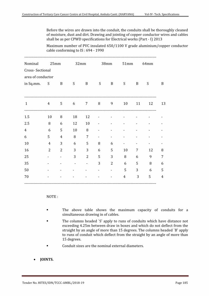
Construction of Tertiary Care Cancer Centre at Civil Hospital, Ambala Cantt. (HARYANA) Vol-IV- Tech. Specifications
Tender No. HITES/IDN/TCCC-AMBL/2018-19 Page 185
Before the wires are drawn into the conduit, the conduits shall be thoroughly cleaned of moisture, dust and dirt. Drawing and jointing of copper conductor wires and cables shall be as per CPWD specifications for Electrical works (Part - I) 2013
Maximum number of PVC insulated 650/1100 V grade aluminium/copper conductor cable conforming to IS : 694 - 1990
-------------------------------------------------------------------------------------------------------
Nominal 25mm 32mm 38mm 51mm 64mm
Cross- Sectional
area of conductor
in Sq.mm. S B S B S B S B S B
-------------------------------------------------------------------------------------------------------
1 4 5 6 7 8 9 10 11 12 13
-------------------------------------------------------------------------------------------------------
1.5 10 8 18 12 - - - - - -
2.5 8 6 12 10 - - - - - -
4 6 5 10 8 - - - - - -
6 5 4 8 7 - - - - - -
10 4 3 6 5 8 6 - - - -
16 2 2 3 3 6 5 10 7 12 8
25 - - 3 2 5 3 8 6 9 7
35 - - - - 3 2 6 5 8 6
50 - - - - - - 5 3 6 5
70 - - - - - - 4 3 5 4
-------------------------------------------------------------------------------------------------------
NOTE :
The above table shows the maximum capacity of conduits for a simultaneous drawing in of cables.
The columns headed `S' apply to runs of conduits which have distance not exceeding 4.25m between draw in boxes and which do not deflect from the straight by an angle of more than 15 degrees. The columns headed `B' apply to runs of conduit which deflect from the straight by an angle of more than 15 degrees.
Conduit sizes are the nominal external diameters.
JOINTS.
Construction of Tertiary Care Cancer Centre at Civil Hospital, Ambala Cantt. (HARYANA) Vol-IV- Tech. Specifications
Tender No. HITES/IDN/TCCC-AMBL/2018-19 Page 186
All joints shall be made at main switches, distribution board socket and switch boxes only. No joint shall be made in conduits and junction boxes. Conductors shall be continuous from outlet to outlet.
LOAD BALANCING
Balancing of circuits in three-phase installation shall be planned before the commencement of wiring and shall be strictly adhered to.
COLOUR CODE FOR CIRCUIT WIRING
Colour code for circuit and sub main wiring installation shall be Red, Yellow, and Blue for three phases. Black for neutral and yellow/green or green only for earth in case of insulated earth wire.
CLASSIFICATION OF POINTS.
General
Classification and measurement of Point wiring shall be as per CPWD specification for Electrical Works (Part-I-Internal) 2013.
Point Wiring (Modular)
Definition of Point Wiring:
A point (other than socket outlet point) shall include all work necessary in complete wiring to the light points/fan/exhaust fan/call bell point from the controlling switch/MCB. The scope of wiring for a point shall, however, include the wiring work necessary in tapping from another point in the same distribution circuit i.e. from first switch board (wiring from distribution board to first switch box is covered in the circuit wiring and is not in the scope of point wiring) to subsequent switch board(s) in the same distribution circuit. The point wiring includes all materials specified below including chasing the wall (in case of recessed wiring in wall), fixing the conduit and making the wall good as it originally was. It also includes supply, drawing, testing and commissioning of wires.
Scope of point wiring
Following shall be deemed to be included in point wiring.
a. Supply & fixing conduit & conduit accessories for the same and wiring cables (including supplying and drawing wires) between the switch box and the point outlet.
b. All fixing accessories such as clips, nails, screws, phil plug, rawl plug etc. as required.
c. Modular switches, modular base plates and modular cover plates over the same. regulators, sockets with Metal boxes etc. in recessed or surface .
d. Outlet boxes, junction boxes, pull-through boxes etc. but excluding modular metal boxes if any, provided the switchboards for loose wires/conduit terminations.
e. In case of recessed wiring in wall the scope includes chasing of wall, fixing the conduit and making the wall good as it originally was.
f. Control modular switch (5/6A) as specified.
g. Ceiling rose or connector (in case of points for ceiling/exhaust fan point, prewired light fittings and call bells).
h. Connections to ceiling rose, connector, socket outlet, lamp holder, switch etc.
Construction of Tertiary Care Cancer Centre at Civil Hospital, Ambala Cantt. (HARYANA) Vol-IV- Tech. Specifications
Tender No. HITES/IDN/TCCC-AMBL/2018-19 Page 187
i. Interconnecting wiring between points on the same circuit, in the same switch box or from another. Interconnecting wiring from first switchboard to subsequent switch board(s).
j. Protective (loop earthing) conductor as required from one metallic switch box to another in the distribution circuits, and from switchboard to each point (light/fan/exhaust fan/call bell etc).
k. Bushed conduit where wiring cables pass through wall etc.
l. Ceiling rose (in the case of pendants except stiff pendants).
m. Lamp holder (in the case of goose neck type wall bracket, batten holder and fittings which are not pre-wired).
n. Back Plate (in the case of stiff pendants).
Circuit and Submain Wiring
Circuit Wiring
Circuit wiring shall mean the wiring from the distribution board up to the tapping point for the nearest first point of that distribution circuit i.e. up to the nearest first switch box.
Submain Wiring
Submain wiring shall mean the wiring from one main/distribution switchboard to another.
Power Plug Wiring
6A Plug Wiring
Wiring for all 6 A Socket Outlets shall be done with 2 X 2.5 sqmm PVC insulated copper wire in suitable size MS Conduit (including supplying and fixing MS Conduit) along with the earth wire. Up to 3 points may be connected to one circuit.
16A Power Plug Wiring
Wiring for all 16 A Socket Outlets/Geyser point shall be done with 2X4 sq mm PVC insulated copper wire in suitable size MS Conduit (including supplying and fixing MS Conduit) along with the earth wire, directly from the MCB- Distribution Board or from one power socket outlet to another in case of computer power points. Looping shall not be done in general 16A power points (other than computer power points).
Wiring for 20A Metal Clad Socket Outlets
Wiring for all 20A Metal Clad Socket Outlets shall be done with 2X6 sqmm PVC insulated copper wire in suitable size MS Conduit (including supplying and fixing MS Conduit) along with the earth wire directly from the MCB-Distribution Board. Measurement of wiring for 20A Metal Clad Socket outlet shall be done on linear basis i.e. complete wiring directly from MCB-Distribution Board to the socket outlet.
CONDUCTOR SIZE.
Wiring shall be carried out with following sizes of PVC insulated stranded single core copper conductor wire/cable.
i. Light Point. - 1.5 sq.mm
ii. Ceiling /Cabin/Exhaust Fan Point - 1.5 sq.mm

Construction of Tertiary Care Cancer Centre at Civil Hospital, Ambala Cantt. (HARYANA) Vol-IV- Tech. Specifications
Tender No. HITES/IDN/TCCC-AMBL/2018-19 Page 188
iii. Call Bell Point - 1.5 sq.mm
iv. 6A Plug Point/ UPS Computer outlets (up to 3 outlets on one ckt.) - 2.5 sq.mm
v. Circuit Wiring - 2.5 sq.mm
vi. General Power Point – 4 sq.mm
vii 20A Industrial Socket Outlet – 6 Sqmm
viii Special Power Point – 6 Sqmm
ix A/C Box with 32A MCB- 6 Sqmm
LIGHTING FIXTURE AND FANS
GENERAL
a. The Contractor shall supply and install all LED Lighting fixtures as per IS 4347 for Hospital Lighting.
b. All fixtures shall be delivered to the building complete with suspension accessories, canopies, hanging devices, sockets, holders, reflectors, ballasts, diffusing material, louvers, plaster frames, recessing boxes, etc. all wired and assembled as indicated.
c. Full size shop detail drawings of special fixture or lighting equipment, where called for in the fixtures, shall be submitted to the Engineer In Charge for approval.
d. Fixtures, housing, frame or canopy, shall provide a suitable cover for fixture outlet box or fixture opening.
e. Fixtures shall comply with all applicable requirements as herein outlined unless otherwise specified or shown on the Drawings.
f. Manufacturer's name and catalogue number of light fixtures, fans, switchgears etc. shall be strictly adhered.
g. Fixtures shall bear manufacturer's name and the factory inspection label.
h. Fixtures shall be completely wired and constructed to comply with the IEE wiring regulations requirements for lighting fixtures, unless otherwise specified.
i. Revamping the fixture shall be possible without having to remove the fixture from its place.
j. Lamps of the proper type, wattage and voltage rating shall be furnished and installed in each fixture.
k. For Labs, ICU, CCU and other Critical Areas, Clean Room LED Light Fixtures shall be provided to maintain requisite Lux level as per NBC 2016, ECBC and as directed by Engineer-In-Charge.
INSTALLATION
Fixtures shall be installed at mounting heights as detailed on the Drawings or as instructed on site by the Engineer-In -charge.
Construction of Tertiary Care Cancer Centre at Civil Hospital, Ambala Cantt. (HARYANA) Vol-IV- Tech. Specifications
Tender No. HITES/IDN/TCCC-AMBL/2018-19 Page 189
Pendent fixtures within the same room or area shall be installed plumb and at a uniform height from the finished floor. Adjustment of height shall be made during installation.
Flush mounted recessed fixtures, shall be installed so as to completely eliminate leakage of light within the fixture and between the fixture and adjacent finish.
Fixtures mounted outlet boxes shall be rigidly secured to a fixture stud in the outlet box. Hickeys or extension pieces shall be installed where required to facilitate proper installation.
Fixtures located on the exterior of the building shall be installed with non-ferrous metal screws finished to match the fixtures.
LED Light Fixtures -GENERAL
LED Lighting fixtures shall provide luminous efficacy of more than 100 Lumens/ Watt, including Driver & accessories. LED Light Fixtures shall have inbuilt harmonic mechanism to mitigate harmonics.
BALLASTS/ Driver
Ballasts/ Driver shall be electronic type and having high power factor type.
Ballasts shall have manufacturer's lowest sound level and case temperature rise rating.
TESTING
After all lighting fixtures are installed and are connected their respective switches, test all fixtures to ensure operation on their correct switch in the presence of the engineer.
All non-operating fixtures or ones connected to the wrong or inconveniently located switch shall be correctly connected as directed by the Engineer In- charge. Stickers are to be placed on each light fixture w.r.t. controlling switch of respective light.
CEILING FANS
All ceiling fans shall be provided with suspension arrangement in the concrete/slab/roof members. Contractor to ensure that provision are kept at appropriate stage at locations shown on the drawing. Fan box with MS hook shall be as per CPWD specification. Ceiling fan shall be Heavy Duty, double ball bearing type, copper wound motor complete with canopy, down rod, blades etc. and shall conform to relevant IS Standards. Ceiling Fans shall be white in colour. Ceiling fan shall be provided with electronic regulator. Electronic Regulator shall be suitable for 240 volts A.C supply 50 Hz and shall be of continuous duty type and with BEE Star rating. Ceiling Fans shall be 5-Star BEE rated & comply to ECBC norms.
EXHAUST FANS
Exhaust fans shall be heavy-duty type with double ball bearing and conforming to IS 2312 (latest revision). Exhaust fan shall be complete with copper wound motor, capacitor, Louver/shutter, frame and mounting bracket. Exhaust fan shall be suitable for operation on 240 volts single phase A.C supply with BEE 5-star rating & comply to ECBC norms.
Construction of Tertiary Care Cancer Centre at Civil Hospital, Ambala Cantt. (HARYANA) Vol-IV- Tech. Specifications
Tender No. HITES/IDN/TCCC-AMBL/2018-19 Page 190
DISTRIBUTION BOARDS & MCBs
General
DISTRIBUTION BOARDS
As a general practice MCB type double door DB shall be used. Provision of Vertical type MCB DBs is to be considered in areas where 3-phase outlets are also required:
Provisions in MCB DB:
i) Recess/ surface type with integral loose wire box.
ii) Phase/neutral/ earth terminal blocks for termination of incoming & outgoing wires.
iii) DIN channel for mounting MCBs.
iv) Arrangement for mounting incomer MCB/RCCB/RCBO/MCCB as required.
v) Copper Bus Bar.
vi) Earthing terminals.
vii) Interconnection between terminal block/ incoming switch/ bus bar/ neutral/ terminal block/ earth terminal connector with specified size of FRLS pre insulated copper conductor cable duly fitted with copper lugs/ thimbles.
ix) Termination block should be suitable for termination of conductor/ cable of required size but minimum rated cross section of the terminal blocks should be 6 sq. mm.
x) Terminal block shall be made of flame retardant polyamide material.
xi) Coloured terminal blocks and FRLS wires for easy identification of RYB phases, Neutral and Earth.
xii) DB shall be provided with a detachable cassette for safe removal of MCBs, RCCBs. Terminal connectors from the DB without loosening the internal cable connections of phase and neutral circuits.
xiii) The DB shall have peel able poly layer on the cover for protection from cement, plaster, paints etc during the construction period.
xiv) Detachable plate with knock out holes shall be provided at the top/ bottom of board. Complete board shall be factory fabricated and pre-wired in factory, ready for installation at site. The box and cover shall be fabricated from 1.6 mm sheet steel, properly pretreated, phosphotized with powder coated finish.
xv) DB shall be of double door construction provided with hinged cover in the front.
xvi) DB doors shall be suitably earthed.
Distribution Board shall be standard type. Distribution boards shall contain miniature circuit breakers. Miniature circuit breakers shall be quick make and quick break type with trip free mechanism. MCB shall have thermal and magnetic short circuit protection. All miniature circuit breakers shall be of minimum 10 kA rated rupturing capacity unless otherwise specified.
Neutral busbars shall be provided with the same number of terminals, as there are single ways on the board, in addition to the terminals for incoming mains. An earth bar of similar size as the neutral bar shall also be provided. All live parts shall be screened from the front. Ample clearance shall be provided between all live metal and the earth case and
Construction of Tertiary Care Cancer Centre at Civil Hospital, Ambala Cantt. (HARYANA) Vol-IV- Tech. Specifications
Tender No. HITES/IDN/TCCC-AMBL/2018-19 Page 191
adequate space for all incoming and outgoing cables. A circuit identification card in clear plastic cover shall be provided for each distribution board.
MCB's shall be provided on the phase of each circuit. The individual banks of MCB's shall be detachable. There shall be ample space behind the banks of MCB's to accommodate all the wiring. All the distribution boards shall be completely factory wired, ready for connections. All the terminals shall have adequate current rating and size to suit individual feeder requirements. Each circuit shall be clearly numbered from left to right to correspond with wiring diagram. All the switches and circuits shall be distinctly marked with a small description of the service installed.
Earth Leakage Circuit Breaker/Residual Current Circuit Breaker shall be provided in each Distribution Board as required. Earth Leakage Circuit Breaker shall be current operated type and of 30 mA sensitivity unless otherwise specified. It shall also provide over-current and short circuit protection i.e. it shall be MCB-cum-RCCB (Residual Current Circuit Breaker). In case ELCB doesn’t have inbuilt short circuit protection, same rating MCB have to be provided for short circuit protection along with ELCB. Cost of this MCB is deemed to be included in the cost of ELCB. ELCB shall be housed within the Distribution Board.
Distribution Boards shall be ready for connections and shall be inspected in the factory by Electrical Engineer- In charge before dispatch.
Before procurement of Distribution Boards, MCB’s, ELCB’s (incomer and outgoings) etc., the contractor has to take approval of the DB Schedule/Drawings of each DB from the Electrical Engineer In Charge. The whole unit i.e. Distribution Board, MCB’s, ELCB’s etc. shall come from the manufactures premises/workshop. After inspection and clearance from the HITES Electrical Engineer the same may be dispatched to site for installation. However if a single component (such as ELCB or MCB or DB) is required for any reason such as replacement, increase in no. of circuits in the DB, change in the load of existing circuit, change in the total load on a particular DB etc., the same may be ordered separately.
TELEPHONE SYSTEM
Point Wiring for Telephone System
a) The point wiring shall be carried out with telephones wires/cables, 2 pair, un-armoured, PVC insulated and sheath, 0.51 mm dia annealed tinned copper conductor, conforming to ITD specification S/WS-113C armouring and outer sheath as per IS: 1554 (Part -I) in 25 mm steel conduit (one pair always remaining spare for one point). If more than one telephone point has to be provided at one point, multi-core, un-armoured telephone cable shall be used (pairs required are equal to 2 x no. of points) in suitable size conduit. If specifically mentioned in schedule of quantities, instead of ordinary PVC insulated telephone wire as specified above, UTP cable Cat – 6 to be supplied & laid.
b) The item includes providing and fixing/laying of conduit, switch boxes, socket for telephones connection and telephone wires/cables etc.
Minimum diameter of steel conduit for telephone wiring shall be 25 mm.
a) The point shall commence from the main telephone tag box/sub tag box and would terminate at outlet box of point. Connection at both ends included in point wiring.
b) Steel conduit, accessories, draw out boxes, switch boxes etc. shall be supplied & laid as per the details given at 2.0.
c) Each telephone point shall have 1 no. flush type RJ11 telephone jack fixed on 3 mm thick, hylem sheet in MS outlet box (size 100 x 100 mm). More than one telephone socket outlet (maximum 2 nos.) can be fixed on one outlet box, provided these points
Construction of Tertiary Care Cancer Centre at Civil Hospital, Ambala Cantt. (HARYANA) Vol-IV- Tech. Specifications
Tender No. HITES/IDN/TCCC-AMBL/2018-19 Page 192
are at one place and multi-pair (more than 2 pair) telephone cable has been drawn to this point from tag box. However if specified in schedule of quantities, telephone cord grid plate mounted outlet unit (RJ – 11) with moulded cover plate in recessed galvanised MS box to be provided.
d) Joint in telephone wiring (between main tag box/sub tag box and outlet box of point) shall not be allowed and the contractor should bear the wastage of wire if resulted due to this special requirement of telephone system. No looping in telephone system is allowed unless specifically shown in the drawing or instructed by site engineer in the drawing/instruction book.
e) Telephone and computer data wiring can be drawn in the same conduit, provided after drawing wires, 50% of conduit cross sectional area is free. However independent PVC insulated telephone & data wire of suitable size shall be used for telephone and computer data.
f) To identify each pair of multi-pair telephone wire/cable, PVC indication numbers shall be put on both end of pair just before termination.
Point Wiring (Computer Data)
a) The point wiring shall be carried out with data cable of 4 (FOUR) pairs (or as specified in schedule of quantities) un-armoured, PVC insulated and sheath, 0.50 mm dia annealed tinned copper conductor (CAT 5e or CAT 6 as specified in schedule of quantities), in suitable size conduit.
b) The item includes providing and fixing/laying of conduit, switch boxes, socket for computer connection and data wires/cables etc
Minimum diameter of steel conduit for telephone wiring shall be 25 mm.
a) The point shall commence from the main junction box or sub junction box at floor of computer data system, and would terminate at outlet box of point. Connection at both ends of cable shall be carried out by purchaser.
b) General specification for concealed/surface conduit system of telephone system (clause no. 5.1 (c), 5.1 (d) & 5.1 (g) shall be applicable for this system also.
c) Joint in computer data cable (between junction box and outlet box of point) shall not be allowed and the contractor should bear the wastage of cable if resulted due to this special requirement of computer data system.
Telephone Cable Work (Underground System)
a) The cable shall be suitable for telephone system of suitable pairs (as specified in schedule of quantities), steel armoured, PVC insulated and sheath, 0.51 mm dia annealed tinned copper conductor, conforming to ITD specification S/WS-113C armouring and outer sheath as per IS:1554(Part-I). All telephone cables for underground laying shall be jelly filled type.
b) Specification for laying of telephone cable in underground system shall be same as for electrical system (clause no. 4.2,4.3,4.4 and 4.5 and the same shall be followed.
Telephone Tag Boxes
a) These shall be of KRONE type using insulation displacement technique in which there is no stripping or soldering of wire, of MS sheet 14 G with connector suitable for telephone connection. It shall have hinged MS sheet cover. Tag box to be of sufficient size to not only accommodate required KRONES but also space for dressing of wires.
Television Point Wiring
Construction of Tertiary Care Cancer Centre at Civil Hospital, Ambala Cantt. (HARYANA) Vol-IV- Tech. Specifications
Tender No. HITES/IDN/TCCC-AMBL/2018-19 Page 193
a) only steel conduit minimum 25mm dia shall be provided and laid for all tv wiring. All specifications for conduting shall be same as mentioned above.
b) Co-axial TV cable of single strand tinned copper conductor of diameter 0.80 mm, complete with metallic shield. Cable having signal loss less than 6 db per 100 Mts. for band 1 UHF should be provided and laid.
c) One number TV wall outlet in suitable MS box should be fixed at each receiving end.
d) In each 25 mm dia conduit max. 2 nos. co-axial cables should be drawn. There should be the least possible number of bends in the conduit system.
e) The samples of TV cable & wall outlet should be got approved before installing.
f) Matter to be checked by contractor with purchaser, whether system of each TV point having its own TV antenna is there for the project or cable TV system having common antenna for project is to be followed. This shall be speciallyapplicable if in the project residential quarters are also included. If central cable TV system is their, necessary amplifier, tap-off, and splitters etc. to be provided as per detail drawings and schedule of quantities.
Enhanced Category 6 UTP specifications
a) The UTP shall be 4-pair, with 24 SWG solid or standard copper conductors.
b) The UTP-based cabling system shall have a 160 MHz channel channel bandwidth over a maximum distance of 100m (328 ft) and a channel power sum attenuation-to-crosstalk ratio (PSACR) of 9.6 dB@ 100 MHz using an interconnect or BIX cross connect configuration.
c) The UTP-based cabling system shall use matched components from a single manufacturer, certified to deliver system performance over the lifetime of the application that the cabling system was originally designed to support.
d) The UTP-based cabling system shall comply with the following standards:
Enhanced Category 5 – TIA/EIA Addendum
Category 5 – ANSI/TIA/EIA-568, TIA/EIA TSB67
Class D – CENELEC EN50173
Class D – ISO/IEC 11801
UTP Outlets
a) The outlet UTP connection module and its optional cover shall be available in the following colors: grey, almond, white, black, orange, red, yellow, green, blue, purple and brown.
b) The outlet UTP connection module shall be Power Sum rated, with a power Sum NEXT performance equal to or better than ANSI/TIA/EIA-568 Category 5 pair-to-pair NEXT performance specifications, and shall have a PS5 marking to indicate compliance.
c) The eight-position outlet UTP connection module shall accommodation six-position modular plug cords without damage to either the cord or the module.
d) It shall be possible to inspect and/or re-terminate the UTP cable at the outlet through front access at the face plate.
e) The faceplate housing the outlet UTP connection modules shall have aperture plugs to cover any unused openings in the faceplate.
f) The faceplate housing the outlet UTP connection module in wall mounted single and dual-gang electrical boxes, utility poles and modular furniture (cubical) access points
Construction of Tertiary Care Cancer Centre at Civil Hospital, Ambala Cantt. (HARYANA) Vol-IV- Tech. Specifications
Tender No. HITES/IDN/TCCC-AMBL/2018-19 Page 194
using manufacturer – supplied faceplates and/or adapters, equipped with front, side or angled-entry options for modular cords.
UTP System Testing
a) There are two primary field test parameters for an UTP-based end-to-end cabling system. These are continuity/wire mapping and a visual inspection, both to be performed by the vendor.
b) Continuity/wire mapping is used to verify consistency pair-to-pin terminations at each end of a given cable. It also checks for faulty connections in the run. For each of the eight conductors in the cable, continuity/wire mapping indicates:
Continuity of the channel to the remote end.
Shorts between any two or more conductors.
Crossed pairs.
Reversed pairs.
Split pairs.
Any other wiring.
c) LAN wiring shall be done with Category 6 (CAT 6) wire, if specifically asked for in BOQ.
TELEPHONE TAG BLOCK (TTB / IDF)
CAT-5e (enhanced) unshielded twisted pair cable in MS conduit shall be used to have modern structured cabling network for telephone system, to have latest facilities for Internet and also data cabling. All the telephone Jack must terminated on RJ-11 jacks and installed onto a dual Jack faceplate. Telephone RJ-11 Jacks must be terminated with a BLACK Connector/Jack.
For LAN CAT 6 UTP cables shall be used for interconnecting the RJ 45 outlets to Intermediate Switch (Hub) or directly to IT room, if the running length limit permits. These Intermediate switch shall be installed in a rack/cabinet and located in electrical room of the respective floors. Fibre Optic cable or CAT-6 UTP cable shall be used for backbone to interconnect the Intermediate switch to IT room’s Server rack, as per the design requirement of the specialised Vendor. All the Data Jack must terminated on an 8 wire, 8-position Jack. Each RJ-45 Data Connection will be terminated with a BLUE Data Jack
Only conduit routing & wiring shall be provided by the Electrical contractor and the configuration & wiring shall be done by the Vendor for the IT Networking.
EPABX system, with latest technology will be provided to provide Voice Mail & Call Accounting by costing of all calls made by telephones.
A small cabinet for Low current services shall be provided at the false ceiling level to locate all the terminal points like Tel.Tag block, tap-off box for MATV etc., for interconnecting all the low current outlets (jacks). Each tel. outlet shall be provided a separate wire from the room tag block.
Similarly one CAT-5e wire from the floor TTB/IDF shall be provided for each Tel. Outlet proposed.
A Multi pair box as per BOQ Tel. Cable shall be laid from the Service gate to the Telephone switch room MDF for Direct lines from the Service provider. Some of the lines shall be bypassed to EPABX and shall be directly provided to Top management’s office & Telephone operators for direct communication to outside. Rest of the lines shall be routed through EPABX for the use of patrons & staff through extensions. The following area/desk shall have direct access to outside Tel. lines:
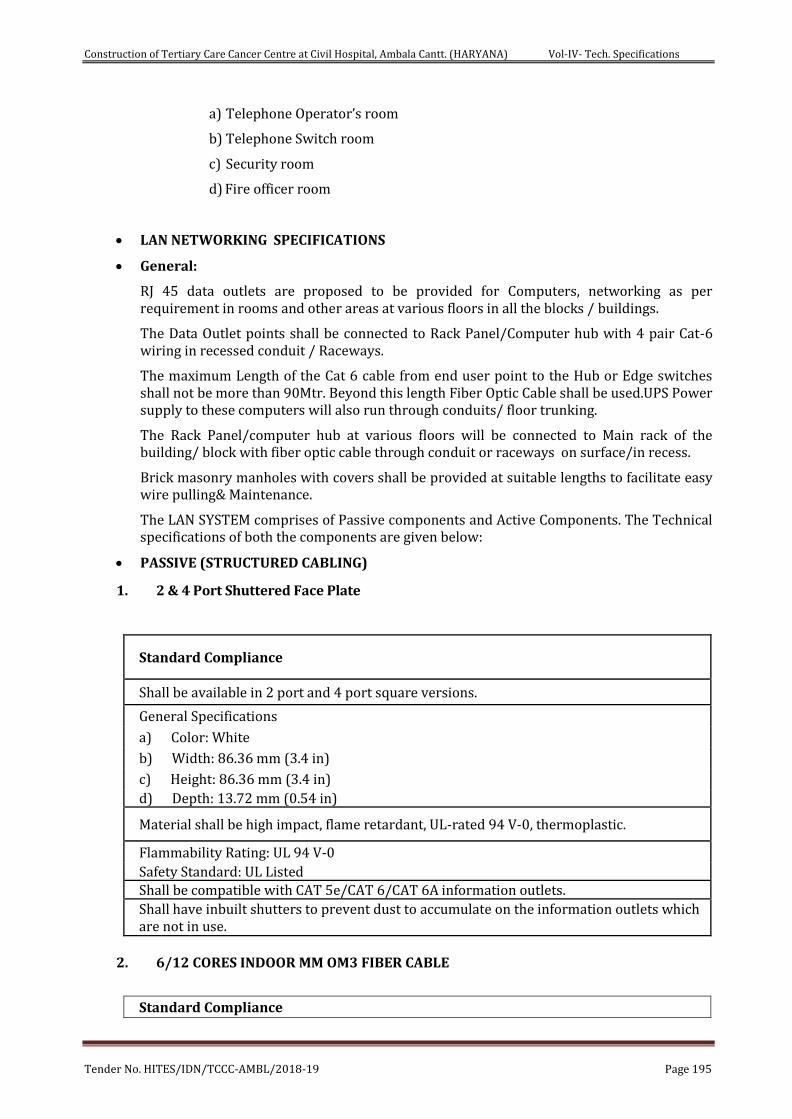
Construction of Tertiary Care Cancer Centre at Civil Hospital, Ambala Cantt. (HARYANA) Vol-IV- Tech. Specifications
Tender No. HITES/IDN/TCCC-AMBL/2018-19 Page 195
a) Telephone Operator’s room
b) Telephone Switch room
c) Security room
d) Fire officer room
LAN NETWORKING SPECIFICATIONS
General:
RJ 45 data outlets are proposed to be provided for Computers, networking as per requirement in rooms and other areas at various floors in all the blocks / buildings.
The Data Outlet points shall be connected to Rack Panel/Computer hub with 4 pair Cat-6 wiring in recessed conduit / Raceways.
The maximum Length of the Cat 6 cable from end user point to the Hub or Edge switches shall not be more than 90Mtr. Beyond this length Fiber Optic Cable shall be used.UPS Power supply to these computers will also run through conduits/ floor trunking.
The Rack Panel/computer hub at various floors will be connected to Main rack of the building/ block with fiber optic cable through conduit or raceways on surface/in recess.
Brick masonry manholes with covers shall be provided at suitable lengths to facilitate easy wire pulling& Maintenance.
The LAN SYSTEM comprises of Passive components and Active Components. The Technical specifications of both the components are given below:
PASSIVE (STRUCTURED CABLING)
1. 2 & 4 Port Shuttered Face Plate
Standard Compliance
Shall be available in 2 port and 4 port square versions.
General Specifications
a) Color: White
b) Width: 86.36 mm (3.4 in)
c) Height: 86.36 mm (3.4 in) d) Depth: 13.72 mm (0.54 in)
Material shall be high impact, flame retardant, UL-rated 94 V-0, thermoplastic.
Flammability Rating: UL 94 V-0 Safety Standard: UL Listed Shall be compatible with CAT 5e/CAT 6/CAT 6A information outlets. Shall have inbuilt shutters to prevent dust to accumulate on the information outlets which are not in use.
2. 6/12 CORES INDOOR MM OM3 FIBER CABLE
Standard Compliance
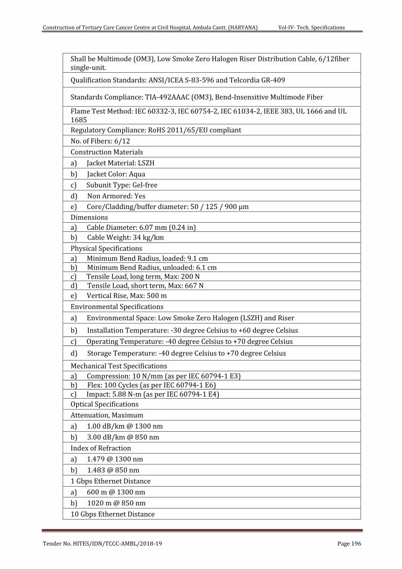
Construction of Tertiary Care Cancer Centre at Civil Hospital, Ambala Cantt. (HARYANA) Vol-IV- Tech. Specifications
Tender No. HITES/IDN/TCCC-AMBL/2018-19 Page 196
Shall be Multimode (OM3), Low Smoke Zero Halogen Riser Distribution Cable, 6/12fiber single-unit.
Qualification Standards: ANSI/ICEA S-83-596 and Telcordia GR-409
Standards Compliance: TIA-492AAAC (OM3), Bend-Insensitive Multimode Fiber
Flame Test Method: IEC 60332-3, IEC 60754-2, IEC 61034-2, IEEE 383, UL 1666 and UL 1685 Regulatory Compliance: RoHS 2011/65/EU compliant
No. of Fibers: 6/12
Construction Materials
a) Jacket Material: LSZH
b) Jacket Color: Aqua
c) Subunit Type: Gel-free
d) Non Armored: Yes
e) Core/Cladding/buffer diameter: 50 / 125 / 900 µm
Dimensions a) Cable Diameter: 6.07 mm (0.24 in) b) Cable Weight: 34 kg/km
Physical Specifications a) Minimum Bend Radius, loaded: 9.1 cm b) Minimum Bend Radius, unloaded: 6.1 cm c) Tensile Load, long term, Max: 200 N d) Tensile Load, short term, Max: 667 N e) Vertical Rise, Max: 500 m
Environmental Specifications
a) Environmental Space: Low Smoke Zero Halogen (LSZH) and Riser
b) Installation Temperature: -30 degree Celsius to +60 degree Celsius
c) Operating Temperature: -40 degree Celsius to +70 degree Celsius
d) Storage Temperature: -40 degree Celsius to +70 degree Celsius
Mechanical Test Specifications a) Compression: 10 N/mm (as per IEC 60794-1 E3) b) Flex: 100 Cycles (as per IEC 60794-1 E6) c) Impact: 5.88 N-m (as per IEC 60794-1 E4) Optical Specifications
Attenuation, Maximum
a) 1.00 dB/km @ 1300 nm
b) 3.00 dB/km @ 850 nm
Index of Refraction
a) 1.479 @ 1300 nm
b) 1.483 @ 850 nm
1 Gbps Ethernet Distance
a) 600 m @ 1300 nm
b) 1020 m @ 850 nm
10 Gbps Ethernet Distance
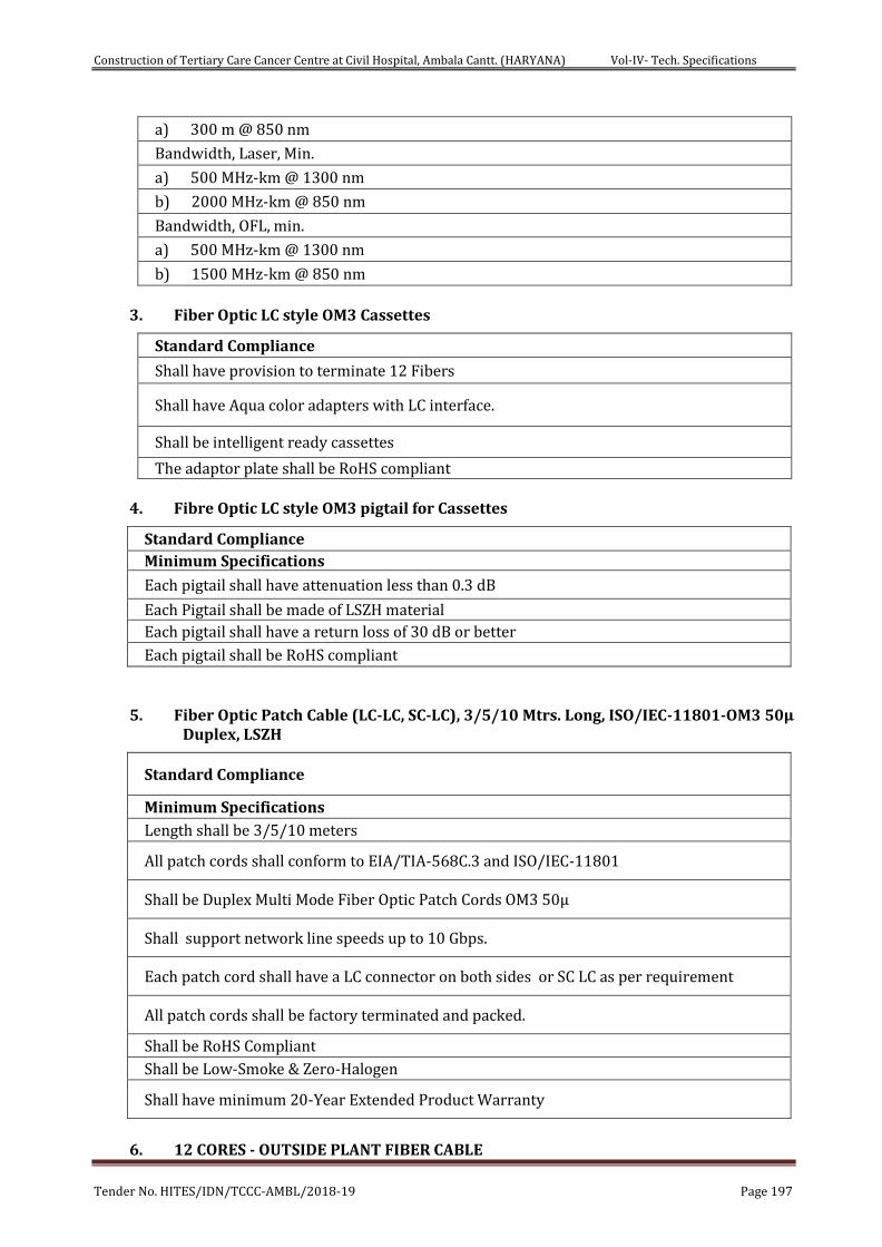
Construction of Tertiary Care Cancer Centre at Civil Hospital, Ambala Cantt. (HARYANA) Vol-IV- Tech. Specifications
Tender No. HITES/IDN/TCCC-AMBL/2018-19 Page 197
a) 300 m @ 850 nm
Bandwidth, Laser, Min.
a) 500 MHz-km @ 1300 nm
b) 2000 MHz-km @ 850 nm
Bandwidth, OFL, min.
a) 500 MHz-km @ 1300 nm
b) 1500 MHz-km @ 850 nm
3. Fiber Optic LC style OM3 Cassettes
Standard Compliance
Shall have provision to terminate 12 Fibers
Shall have Aqua color adapters with LC interface.
Shall be intelligent ready cassettes
The adaptor plate shall be RoHS compliant
4. Fibre Optic LC style OM3 pigtail for Cassettes
Standard Compliance Minimum Specifications
Each pigtail shall have attenuation less than 0.3 dB
Each Pigtail shall be made of LSZH material Each pigtail shall have a return loss of 30 dB or better
Each pigtail shall be RoHS compliant
5. Fiber Optic Patch Cable (LC-LC, SC-LC), 3/5/10 Mtrs. Long, ISO/IEC-11801-OM3 50μ Duplex, LSZH
Standard Compliance
Minimum Specifications
Length shall be 3/5/10 meters
All patch cords shall conform to EIA/TIA-568C.3 and ISO/IEC-11801
Shall be Duplex Multi Mode Fiber Optic Patch Cords OM3 50μ
Shall support network line speeds up to 10 Gbps.
Each patch cord shall have a LC connector on both sides or SC LC as per requirement
All patch cords shall be factory terminated and packed.
Shall be RoHS Compliant
Shall be Low-Smoke & Zero-Halogen
Shall have minimum 20-Year Extended Product Warranty
6. 12 CORES - OUTSIDE PLANT FIBER CABLE
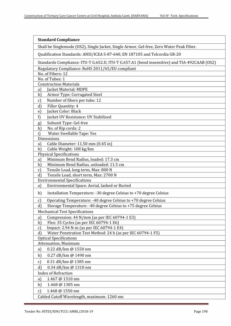
Construction of Tertiary Care Cancer Centre at Civil Hospital, Ambala Cantt. (HARYANA) Vol-IV- Tech. Specifications
Tender No. HITES/IDN/TCCC-AMBL/2018-19 Page 198
Standard Compliance
Shall be Singlemode (OS2), Single Jacket, Single Armor, Gel-free, Zero Water Peak Fiber.
Qualification Standards: ANSI/ICEA S-87-640, EN 187105 and Telcordia GR-20
Standards Compliance: ITU-T G.652.D, ITU-T G.657.A1 (bend insensitive) and TIA-492CAAB (OS2)
Regulatory Compliance: RoHS 2011/65/EU compliant No. of Fibers: 12 No. of Tubes: 1 Construction Materials a) Jacket Material: MDPE b) Armor Type: Corrugated Steel c) Number of fibers per tube: 12 d) Filler Quantity: 4 e) Jacket Color: Black f) Jacket UV Resistance: UV Stabilized
g) Subunit Type: Gel-free h) No. of Rip cords: 2 i) Water Swellable Tape: Yes Dimensions a) Cable Diameter: 11.50 mm (0.45 in) b) Cable Weight: 108 kg/km Physical Specifications a) Minimum Bend Radius, loaded: 17.3 cm b) Minimum Bend Radius, unloaded: 11.5 cm c) Tensile Load, long term, Max: 800 N d) Tensile Load, short term, Max: 2700 N Environmental Specifications a) Environmental Space: Aerial, lashed or Buried
b) Installation Temperature: -30 degree Celsius to +70 degree Celsius
c) Operating Temperature: -40 degree Celsius to +70 degree Celsius d) Storage Temperature: -40 degree Celsius to +75 degree Celsius
Mechanical Test Specifications a) Compression: 44 N/mm (as per IEC 60794-1 E3) b) Flex: 35 Cycles (as per IEC 60794-1 E6) c) Impact: 2.94 N-m (as per IEC 60794-1 E4) d) Water Penetration Test Method: 24 h (as per IEC 60794-1 F5) Optical Specifications Attenuation, Maximum a) 0.22 dB/km @ 1550 nm
b) 0.27 dB/km @ 1490 nm
c) 0.31 dB/km @ 1385 nm d) 0.34 dB/km @ 1310 nm Index of Refraction a) 1.467 @ 1310 nm b) 1.468 @ 1385 nm
c) 1.468 @ 1550 nm Cabled Cutoff Wavelength, maximum: 1260 nm
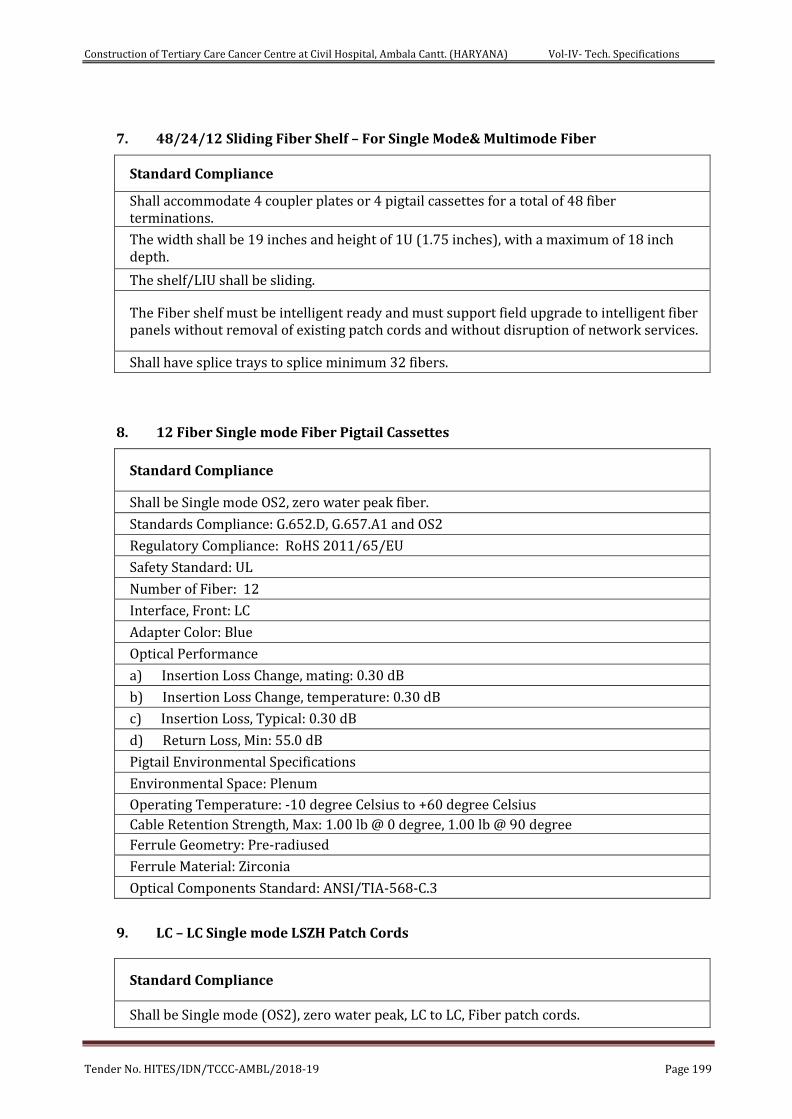
Construction of Tertiary Care Cancer Centre at Civil Hospital, Ambala Cantt. (HARYANA) Vol-IV- Tech. Specifications
Tender No. HITES/IDN/TCCC-AMBL/2018-19 Page 199
7. 48/24/12 Sliding Fiber Shelf – For Single Mode& Multimode Fiber
Standard Compliance
Shall accommodate 4 coupler plates or 4 pigtail cassettes for a total of 48 fiber terminations.
The width shall be 19 inches and height of 1U (1.75 inches), with a maximum of 18 inch depth.
The shelf/LIU shall be sliding.
The Fiber shelf must be intelligent ready and must support field upgrade to intelligent fiber panels without removal of existing patch cords and without disruption of network services.
Shall have splice trays to splice minimum 32 fibers.
8. 12 Fiber Single mode Fiber Pigtail Cassettes
Standard Compliance
Shall be Single mode OS2, zero water peak fiber.
Standards Compliance: G.652.D, G.657.A1 and OS2
Regulatory Compliance: RoHS 2011/65/EU
Safety Standard: UL
Number of Fiber: 12
Interface, Front: LC
Adapter Color: Blue
Optical Performance
a) Insertion Loss Change, mating: 0.30 dB
b) Insertion Loss Change, temperature: 0.30 dB
c) Insertion Loss, Typical: 0.30 dB
d) Return Loss, Min: 55.0 dB
Pigtail Environmental Specifications
Environmental Space: Plenum
Operating Temperature: -10 degree Celsius to +60 degree Celsius Cable Retention Strength, Max: 1.00 lb @ 0 degree, 1.00 lb @ 90 degree
Ferrule Geometry: Pre-radiused
Ferrule Material: Zirconia
Optical Components Standard: ANSI/TIA-568-C.3
9. LC – LC Single mode LSZH Patch Cords
Standard Compliance
Shall be Single mode (OS2), zero water peak, LC to LC, Fiber patch cords.
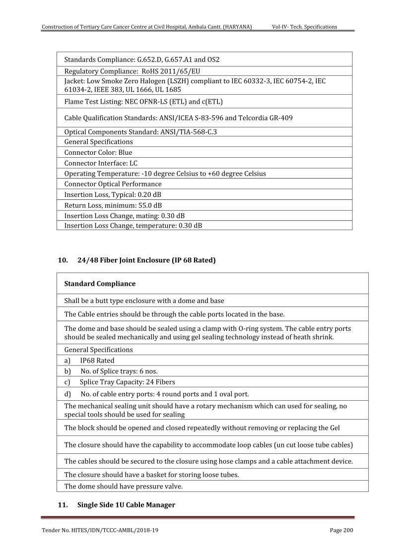
Construction of Tertiary Care Cancer Centre at Civil Hospital, Ambala Cantt. (HARYANA) Vol-IV- Tech. Specifications
Tender No. HITES/IDN/TCCC-AMBL/2018-19 Page 200
Standards Compliance: G.652.D, G.657.A1 and OS2
Regulatory Compliance: RoHS 2011/65/EU Jacket: Low Smoke Zero Halogen (LSZH) compliant to IEC 60332-3, IEC 60754-2, IEC 61034-2, IEEE 383, UL 1666, UL 1685
Flame Test Listing: NEC OFNR-LS (ETL) and c(ETL)
Cable Qualification Standards: ANSI/ICEA S-83-596 and Telcordia GR-409
Optical Components Standard: ANSI/TIA-568-C.3 General Specifications
Connector Color: Blue
Connector Interface: LC
Operating Temperature: -10 degree Celsius to +60 degree Celsius
Connector Optical Performance
Insertion Loss, Typical: 0.20 dB
Return Loss, minimum: 55.0 dB
Insertion Loss Change, mating: 0.30 dB Insertion Loss Change, temperature: 0.30 dB
10. 24/48 Fiber Joint Enclosure (IP 68 Rated)
Standard Compliance
Shall be a butt type enclosure with a dome and base
The Cable entries should be through the cable ports located in the base.
The dome and base should be sealed using a clamp with O-ring system. The cable entry ports should be sealed mechanically and using gel sealing technology instead of heath shrink.
General Specifications
a) IP68 Rated
b) No. of Splice trays: 6 nos.
c) Splice Tray Capacity: 24 Fibers
d) No. of cable entry ports: 4 round ports and 1 oval port.
The mechanical sealing unit should have a rotary mechanism which can used for sealing, no special tools should be used for sealing
The block should be opened and closed repeatedly without removing or replacing the Gel
The closure should have the capability to accommodate loop cables (un cut loose tube cables)
The cables should be secured to the closure using hose clamps and a cable attachment device.
The closure should have a basket for storing loose tubes.
The dome should have pressure valve.
11. Single Side 1U Cable Manager
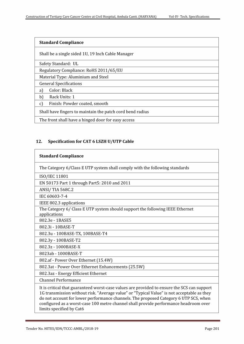
Construction of Tertiary Care Cancer Centre at Civil Hospital, Ambala Cantt. (HARYANA) Vol-IV- Tech. Specifications
Tender No. HITES/IDN/TCCC-AMBL/2018-19 Page 201
Standard Compliance
Shall be a single sided 1U, 19 Inch Cable Manager
Safety Standard: UL
Regulatory Compliance: RoHS 2011/65/EU
Material Type: Aluminium and Steel
General Specifications
a) Color: Black
b) Rack Units: 1
c) Finish: Powder coated, smooth
Shall have fingers to maintain the patch cord bend radius
The front shall have a hinged door for easy access
12. Specification for CAT 6 LSZH U/UTP Cable
Standard Compliance
The Category 6/Class E UTP system shall comply with the following standards
ISO/IEC 11801
EN 50173 Part 1 through Part5: 2010 and 2011
ANSI/ TIA 568C.2
IEC 60603-7-4
IEEE 802.3 applications The Category 6/ Class E UTP system should support the following IEEE Ethernet applications 802.3e - 1BASE5
802.3i - 10BASE-T
802.3u - 100BASE-TX, 100BASE-T4
802.3y - 100BASE-T2
802.3z - 1000BASE-X
8023ab - 1000BASE-T
802.af - Power Over Ethernet (15.4W)
802.3at - Power Over Ethernet Enhancements (25.5W)
802.3az - Energy Efficient Ethernet
Channel Performance
It is critical that guaranteed worst-case values are provided to ensure the SCS can support 1G transmission without risk. “Average value” or “Typical Value” is not acceptable as they do not account for lower performance channels. The proposed Category 6 UTP SCS, when configured as a worst-case 100 metre channel shall provide performance headroom over limits specified by Cat6
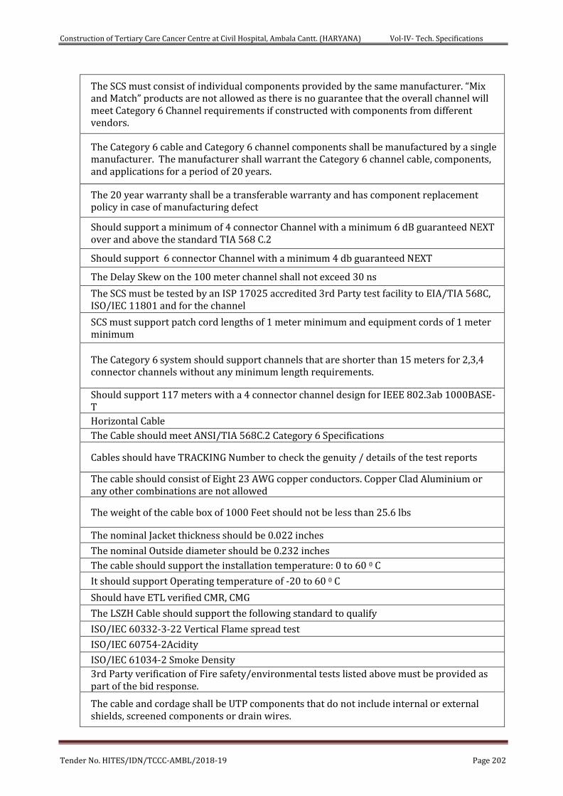
Construction of Tertiary Care Cancer Centre at Civil Hospital, Ambala Cantt. (HARYANA) Vol-IV- Tech. Specifications
Tender No. HITES/IDN/TCCC-AMBL/2018-19 Page 202
The SCS must consist of individual components provided by the same manufacturer. “Mix and Match” products are not allowed as there is no guarantee that the overall channel will meet Category 6 Channel requirements if constructed with components from different vendors.
The Category 6 cable and Category 6 channel components shall be manufactured by a single manufacturer. The manufacturer shall warrant the Category 6 channel cable, components, and applications for a period of 20 years.
The 20 year warranty shall be a transferable warranty and has component replacement policy in case of manufacturing defect
Should support a minimum of 4 connector Channel with a minimum 6 dB guaranteed NEXT over and above the standard TIA 568 C.2
Should support 6 connector Channel with a minimum 4 db guaranteed NEXT
The Delay Skew on the 100 meter channel shall not exceed 30 ns
The SCS must be tested by an ISP 17025 accredited 3rd Party test facility to EIA/TIA 568C, ISO/IEC 11801 and for the channel
SCS must support patch cord lengths of 1 meter minimum and equipment cords of 1 meter minimum
The Category 6 system should support channels that are shorter than 15 meters for 2,3,4 connector channels without any minimum length requirements.
Should support 117 meters with a 4 connector channel design for IEEE 802.3ab 1000BASE-T Horizontal Cable
The Cable should meet ANSI/TIA 568C.2 Category 6 Specifications
Cables should have TRACKING Number to check the genuity / details of the test reports
The cable should consist of Eight 23 AWG copper conductors. Copper Clad Aluminium or any other combinations are not allowed
The weight of the cable box of 1000 Feet should not be less than 25.6 lbs
The nominal Jacket thickness should be 0.022 inches
The nominal Outside diameter should be 0.232 inches
The cable should support the installation temperature: 0 to 60 0 C
It should support Operating temperature of -20 to 60 0 C
Should have ETL verified CMR, CMG
The LSZH Cable should support the following standard to qualify
ISO/IEC 60332-3-22 Vertical Flame spread test
ISO/IEC 60754-2Acidity
ISO/IEC 61034-2 Smoke Density 3rd Party verification of Fire safety/environmental tests listed above must be provided as part of the bid response.
The cable and cordage shall be UTP components that do not include internal or external shields, screened components or drain wires.
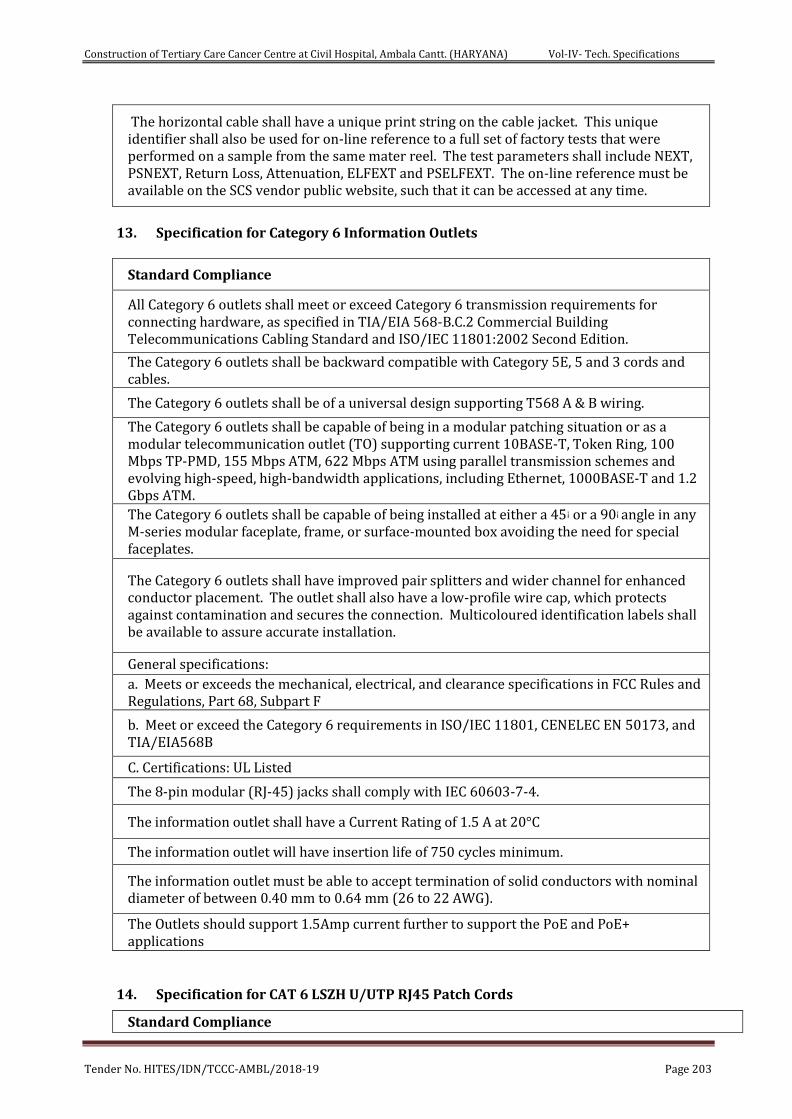
Construction of Tertiary Care Cancer Centre at Civil Hospital, Ambala Cantt. (HARYANA) Vol-IV- Tech. Specifications
Tender No. HITES/IDN/TCCC-AMBL/2018-19 Page 203
The horizontal cable shall have a unique print string on the cable jacket. This unique identifier shall also be used for on-line reference to a full set of factory tests that were performed on a sample from the same mater reel. The test parameters shall include NEXT, PSNEXT, Return Loss, Attenuation, ELFEXT and PSELFEXT. The on-line reference must be available on the SCS vendor public website, such that it can be accessed at any time.
13. Specification for Category 6 Information Outlets
Standard Compliance
All Category 6 outlets shall meet or exceed Category 6 transmission requirements for connecting hardware, as specified in TIA/EIA 568-B.C.2 Commercial Building Telecommunications Cabling Standard and ISO/IEC 11801:2002 Second Edition.
The Category 6 outlets shall be backward compatible with Category 5E, 5 and 3 cords and cables.
The Category 6 outlets shall be of a universal design supporting T568 A & B wiring.
The Category 6 outlets shall be capable of being in a modular patching situation or as a modular telecommunication outlet (TO) supporting current 10BASE-T, Token Ring, 100 Mbps TP-PMD, 155 Mbps ATM, 622 Mbps ATM using parallel transmission schemes and evolving high-speed, high-bandwidth applications, including Ethernet, 1000BASE-T and 1.2 Gbps ATM. The Category 6 outlets shall be capable of being installed at either a 45¡ or a 90¡ angle in any M-series modular faceplate, frame, or surface-mounted box avoiding the need for special faceplates.
The Category 6 outlets shall have improved pair splitters and wider channel for enhanced conductor placement. The outlet shall also have a low-profile wire cap, which protects against contamination and secures the connection. Multicoloured identification labels shall be available to assure accurate installation.
General specifications: a. Meets or exceeds the mechanical, electrical, and clearance specifications in FCC Rules and Regulations, Part 68, Subpart F
b. Meet or exceed the Category 6 requirements in ISO/IEC 11801, CENELEC EN 50173, and TIA/EIA568B
C. Certifications: UL Listed
The 8-pin modular (RJ-45) jacks shall comply with IEC 60603-7-4.
The information outlet shall have a Current Rating of 1.5 A at 20°C
The information outlet will have insertion life of 750 cycles minimum.
The information outlet must be able to accept termination of solid conductors with nominal diameter of between 0.40 mm to 0.64 mm (26 to 22 AWG).
The Outlets should support 1.5Amp current further to support the PoE and PoE+ applications
14. Specification for CAT 6 LSZH U/UTP RJ45 Patch Cords
Standard Compliance
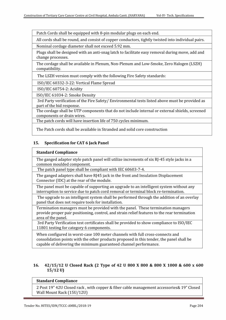
Construction of Tertiary Care Cancer Centre at Civil Hospital, Ambala Cantt. (HARYANA) Vol-IV- Tech. Specifications
Tender No. HITES/IDN/TCCC-AMBL/2018-19 Page 204
Patch Cords shall be equipped with 8-pin modular plugs on each end.
All cords shall be round, and consist of copper conductors, tightly twisted into individual pairs.
Nominal cordage diameter shall not exceed 5.92 mm.
Plugs shall be designed with an anti-snag latch to facilitate easy removal during move, add and change processes.
The cordage shall be available in Plenum, Non-Plenum and Low-Smoke, Zero Halogen (LSZH) compatibility.
The LSZH version must comply with the following Fire Safety standards:
ISO/IEC 60332-3-22: Vertical Flame Spread
ISO/IEC 60754-2: Acidity
ISO/IEC 61034-2: Smoke Density 3rd Party verification of the Fire Safety/ Environmental tests listed above must be provided as part of the bid response. The cordage shall be UTP components that do not include internal or external shields, screened components or drain wires. The patch cords will have insertion life of 750 cycles minimum.
The Patch cords shall be available in Stranded and solid core construction
15. Specification for CAT 6 Jack Panel
Standard Compliance
The ganged adapter style patch panel will utilize increments of six RJ-45 style jacks in a common moulded component. The patch panel type shall be compliant with IEC 60603-7-4.
The ganged adapters shall have RJ45 jack in the front and Insulation Displacement Connector (IDC) at the rear of the module.
The panel must be capable of supporting an upgrade to an intelligent system without any interruption to service due to patch cord removal or terminal block re-termination.
The upgrade to an intelligent system shall be performed through the addition of an overlay panel that does not require tools for installation.
Termination managers must be provided with the panel. These termination managers provide proper pair positioning, control, and strain relief features to the rear termination area of the panel. 3rd Party Verification test certificates shall be provided to show compliance to ISO/IEC 11801 testing for category 6 components.
When configured in worst-case 100 meter channels with full cross-connects and consolidation points with the other products proposed in this tender, the panel shall be capable of delivering the minimum guaranteed channel performance.
16. 42/15/12 U Closed Rack (2 Type of 42 U 800 X 800 & 800 X 1000 & 600 x 600 15/12 U)
Standard Compliance
2 Post 19" 42U Closed rack , with copper & fiber cable management accessories& 19” Closed Wall Mount Rack (15U/12U)

Construction of Tertiary Care Cancer Centre at Civil Hospital, Ambala Cantt. (HARYANA) Vol-IV- Tech. Specifications
Tender No. HITES/IDN/TCCC-AMBL/2018-19 Page 205
2 Nos. of 1U power distribution box, with 10 x IEC - C13 sockets & with 32Amp MCB- terminating on a IP56 power sockets
1 No. Horizontal PDU with 5/15Amp Universal Sockets with 32Amp MCB
Front mounting PVC Cable managers/ guide
Integral Cable management ducts/ arms (on either side) with covers
Cantilever Tray x 1 (19" / 1U/ 255mm - D)
Cable retention bobbins X 5 (both sides) + Window Molding x 6
Cable Hangers (set of 3) x 2 (Right & left side one set each)
Bar, Earthing 42U
Mounting Hardware (Pack of 10) x 5
IP65 Rated Outdoor if used in outdoor environment (Weather resistant)
Testing & Commissioning of Passive Components:
All the passive components shall have their Testing reports from the OEM with Batch No.
There shall be the proper ferruling and Numbering on the Cat 6 /fiber cables. There Shall be
proper dressing of the cables and equipment management inside the racks.
The Cat 6 cable installation measurements shall be done through penta scanning with
standard parameters and shall have the OEM certification for the installation of all the
components.
The optical fiber cable installation shall be checked by the OTDR machine and the reports
shall meet all the parameters of the technical data sheet of the Cable and shall have the OEM
certification for the installation.
After installation & OEM certification Commissioning of the passive components shall be
completed.
ACTIVE COMPONENTS
TECHNICAL SPECIFICATIONS FOR ACTIVE COMPONENTS
Firewall with Unified Threat Management (UTM)
S.N. TECHNICAL SPECIFICATION
1 The UTM solution should be Hardware based, Reliable, purpose-built security appliance with hardened operating system that eliminates the security risks associated with general-purpose operating systems.
2 Should support 1:1 high availability.
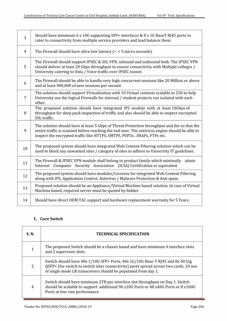
Construction of Tertiary Care Cancer Centre at Civil Hospital, Ambala Cantt. (HARYANA) Vol-IV- Tech. Specifications
Tender No. HITES/IDN/TCCC-AMBL/2018-19 Page 206
3 Should have minimum 6 x 10G supporting SFP+ interfaces & 8 x 1G BaseT RJ45 ports to cater to connectivity from multiple service providers and load balance them.
4 The Firewall should have ultra-low latency (~ < 5 micro seconds).
5 The Firewall should support IPSEC & SSL VPN, inbound and outbound both. The IPSEC VPN should deliver at least 20 Gbps throughput to ensure connectivity with Multiple colleges / University catering to Data / Voice traffic over IPSEC tunnel.
6 The Firewall should be able to handle very high concurrent sessions like 20 Million or above and at least 400,000 of new sessions per second.
7 The solution should support Virtualization with 10 Virtual contexts scalable to 250 to help University use the logical Firewalls for internal / student projects run isolated with each other.
8 The proposed solution should have integrated IPS module with at least 10Gbps of throughput for deep pack inspection of traffic and also should be able to inspect encrypted SSL traffic.
9 The solution should have at least 5 Gbps of Threat Protection throughput and the so that the entire traffic is scanned before reaching the end user. The antivirus engine should be able to inspect the encrypted traffic like HTTPS, SMTPS, POP3s , IMAPs, FTPs etc.
10 The proposed system should have integrated Web Content Filtering solution which can be used to block any unwanted sites / category of sites to adhere to University IT guidelines.
11 The Firewall & IPSEC VPN module shall belong to product family which minimally attain Internet Computer Security Association (ICSA) Certification or equivalent
12 The proposed system should have modules/Licenses for integrated Web Content Filtering along with IPS, Application Control, Antivirus / Malware Protection & Anti spam.
13 Proposed solution should be an Appliance/Virtual Machine based solution. In case of Virtual Machine based, required server must be quoted by bidder.
14 Should have direct OEM TAC support and hardware replacement warranty for 5 Years.
1. Core Switch
S. N. TECHNICAL SPECIFICATION
1 The proposed Switch should be a chassis based and have minimum 4 interface slots and 2 supervisor slots.
2 Switch should have 48x 1/10G SFP+ Ports, 48x 1G/10G Base-T RJ45 and 8x 40 Gig QSFP+ (for switch to switch inter connectivity) ports spread across two cards. 24 nos of single mode LR transceivers should be populated from day 1.
4 Switch should have minimum 2TB per interface slot throughput on Day 1. Switch should be scalable to support additional 96 x10G Ports or 48 x40G Ports or 8 x100G Ports at line rate performance
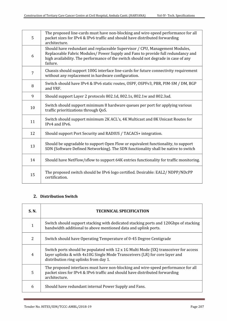
Construction of Tertiary Care Cancer Centre at Civil Hospital, Ambala Cantt. (HARYANA) Vol-IV- Tech. Specifications
Tender No. HITES/IDN/TCCC-AMBL/2018-19 Page 207
5 The proposed line-cards must have non-blocking and wire-speed performance for all packet sizes for IPv4 & IPv6 traffic and should have distributed forwarding architecture.
6
Should have redundant and replaceable Supervisor / CPU, Management Modules, Replaceable Fabric Modules/ Power Supply and Fans to provide full redundancy and high availability. The performance of the switch should not degrade in case of any failure.
7 Chassis should support 100G interface line-cards for future connectivity requirement without any replacement in hardware configuration.
8 Switch should have IPv4 & IPv6 static routes, OSPF, OSPFv3, PBR, PIM-SM / DM, BGP and VRF.
9 Should support Layer 2 protocols 802.1d, 802.1s, 802.1w and 802.3ad.
10 Switch should support minimum 8 hardware queues per port for applying various traffic prioritizations through QoS.
11 Switch should support minimum 2K ACL's, 4K Multicast and 8K Unicast Routes for IPv4 and IPv6.
12 Should support Port Security and RADIUS / TACACS+ integration.
13 Should be upgradable to support Open Flow or equivalent functionality, to support SDN (Software Defined Networking). The SDN functionality shall be native to switch
14 Should have NetFlow/sflow to support 64K entries functionality for traffic monitoring.
15 The proposed switch should be IPv6 logo certified. Desirable: EAL2/ NDPP/NDcPP certification.
2. Distribution Switch
S. N. TECHNICAL SPECIFICATION
1 Switch should support stacking with dedicated stacking ports and 120Gbps of stacking bandwidth additional to above mentioned data and uplink ports.
2 Switch should have Operating Temperature of 0-45 Degree Centigrade
4 Switch ports should be populated with 12 x 1G Multi Mode (SX) transceiver for access layer uplinks & with 4x10G Single Mode Transceivers (LR) for core layer and distribution ring uplinks from day 1.
5 The proposed interfaces must have non-blocking and wire-speed performance for all packet sizes for IPv4 & IPv6 traffic and should have distributed forwarding architecture.
6 Should have redundant internal Power Supply and Fans.
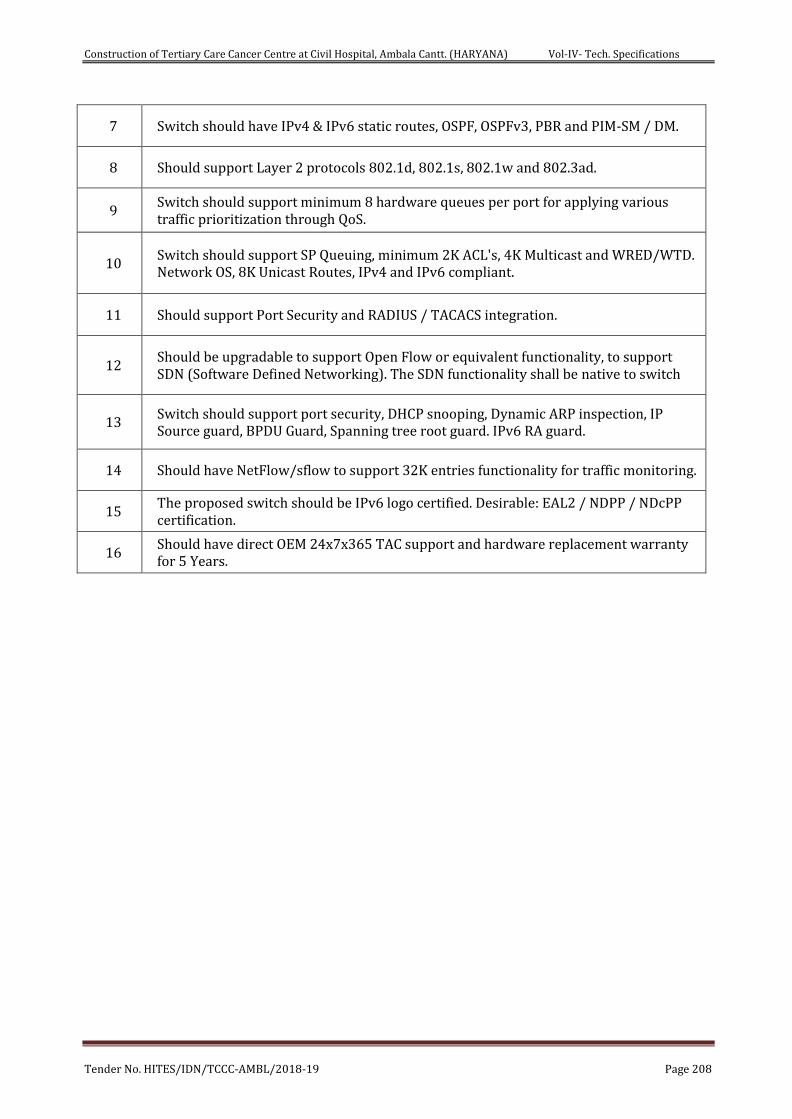
Construction of Tertiary Care Cancer Centre at Civil Hospital, Ambala Cantt. (HARYANA) Vol-IV- Tech. Specifications
Tender No. HITES/IDN/TCCC-AMBL/2018-19 Page 208
7 Switch should have IPv4 & IPv6 static routes, OSPF, OSPFv3, PBR and PIM-SM / DM.
8 Should support Layer 2 protocols 802.1d, 802.1s, 802.1w and 802.3ad.
9 Switch should support minimum 8 hardware queues per port for applying various traffic prioritization through QoS.
10 Switch should support SP Queuing, minimum 2K ACL's, 4K Multicast and WRED/WTD. Network OS, 8K Unicast Routes, IPv4 and IPv6 compliant.
11 Should support Port Security and RADIUS / TACACS integration.
12 Should be upgradable to support Open Flow or equivalent functionality, to support SDN (Software Defined Networking). The SDN functionality shall be native to switch
13 Switch should support port security, DHCP snooping, Dynamic ARP inspection, IP Source guard, BPDU Guard, Spanning tree root guard. IPv6 RA guard.
14 Should have NetFlow/sflow to support 32K entries functionality for traffic monitoring.
15 The proposed switch should be IPv6 logo certified. Desirable: EAL2 / NDPP / NDcPP certification.
16 Should have direct OEM 24x7x365 TAC support and hardware replacement warranty for 5 Years.
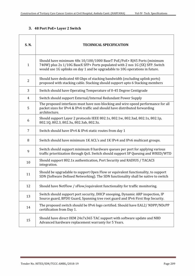
Construction of Tertiary Care Cancer Centre at Civil Hospital, Ambala Cantt. (HARYANA) Vol-IV- Tech. Specifications
Tender No. HITES/IDN/TCCC-AMBL/2018-19 Page 209
3. 48 Port PoE+ Layer 2 Switch
S. N. TECHNICAL SPECIFICATION
1 Should have minimum 48x 10/100/1000 BaseT PoE/PoE+ RJ45 Ports (minimum 740W) plus 2x 1/10G BaseX SFP+ Ports populated with 2 nos 1G (SX) SFP. Switch would use 1G uplinks on day 1 and be upgradable to 10G operations in future.
2 Should have dedicated 48 Gbps of stacking bandwidth (excluding uplink ports) proposed with stacking cable. Stacking should support upto 6 Stacking members
3 Switch should have Operating Temperature of 0-45 Degree Centigrade
4 Switch should support External/Internal Redundant Power Supply
5 The proposed interfaces must have non-blocking and wire-speed performance for all packet sizes for IPv4 & IPv6 traffic and should have distributed forwarding architecture.
6 Should support Layer 2 protocols IEEE 802.1s, 802.1w, 802.3ad, 802.1x, 802.1p, 802.1Q, 802.3, 802.3u, 802.3ab, 802.3z.
7 Switch should have IPv4 & IPv6 static routes from day 1
8 Switch should have minimum 1K ACL’s and 1K IPv4 and IPv6 multicast groups.
9 Switch should support minimum 8 hardware queues per port for applying various traffic prioritization through QoS. Switch should support SP Queuing and WRED/WTD
10 Should support 802.1x authentication, Port Security and RADIUS / TACACS integration.
11 Should be upgradable to support Open Flow or equivalent functionality, to support SDN (Software Defined Networking). The SDN functionality shall be native to switch
12 Should have NetFlow / sFlow/equivalent functionality for traffic monitoring.
13 Switch should support port security, DHCP snooping, Dynamic ARP inspection, IP Source guard, BPDU Guard, Spanning tree root guard and IPv6 First Hop Security.
14 The proposed switch should be IPv6 logo certified. Should have EAL2/ NDPP/NDcPP certification from Day 1.
15 Should have direct OEM 24x7x365 TAC support with software update and NBD Advanced hardware replacement warranty for 5 Years.
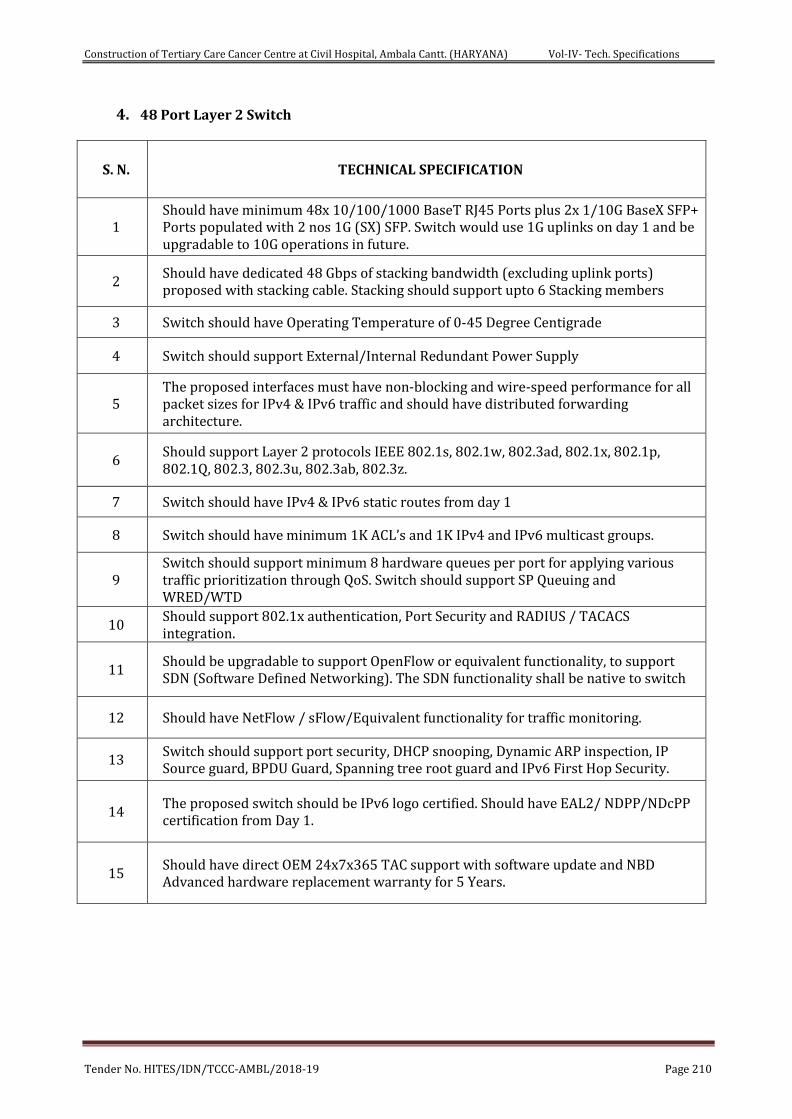
Construction of Tertiary Care Cancer Centre at Civil Hospital, Ambala Cantt. (HARYANA) Vol-IV- Tech. Specifications
Tender No. HITES/IDN/TCCC-AMBL/2018-19 Page 210
4. 48 Port Layer 2 Switch
S. N. TECHNICAL SPECIFICATION
1 Should have minimum 48x 10/100/1000 BaseT RJ45 Ports plus 2x 1/10G BaseX SFP+ Ports populated with 2 nos 1G (SX) SFP. Switch would use 1G uplinks on day 1 and be upgradable to 10G operations in future.
2 Should have dedicated 48 Gbps of stacking bandwidth (excluding uplink ports) proposed with stacking cable. Stacking should support upto 6 Stacking members
3 Switch should have Operating Temperature of 0-45 Degree Centigrade
4 Switch should support External/Internal Redundant Power Supply
5 The proposed interfaces must have non-blocking and wire-speed performance for all packet sizes for IPv4 & IPv6 traffic and should have distributed forwarding architecture.
6 Should support Layer 2 protocols IEEE 802.1s, 802.1w, 802.3ad, 802.1x, 802.1p, 802.1Q, 802.3, 802.3u, 802.3ab, 802.3z.
7 Switch should have IPv4 & IPv6 static routes from day 1
8 Switch should have minimum 1K ACL’s and 1K IPv4 and IPv6 multicast groups.
9 Switch should support minimum 8 hardware queues per port for applying various traffic prioritization through QoS. Switch should support SP Queuing and WRED/WTD
10 Should support 802.1x authentication, Port Security and RADIUS / TACACS integration.
11 Should be upgradable to support OpenFlow or equivalent functionality, to support SDN (Software Defined Networking). The SDN functionality shall be native to switch
12 Should have NetFlow / sFlow/Equivalent functionality for traffic monitoring.
13 Switch should support port security, DHCP snooping, Dynamic ARP inspection, IP Source guard, BPDU Guard, Spanning tree root guard and IPv6 First Hop Security.
14 The proposed switch should be IPv6 logo certified. Should have EAL2/ NDPP/NDcPP certification from Day 1.
15 Should have direct OEM 24x7x365 TAC support with software update and NBD Advanced hardware replacement warranty for 5 Years.
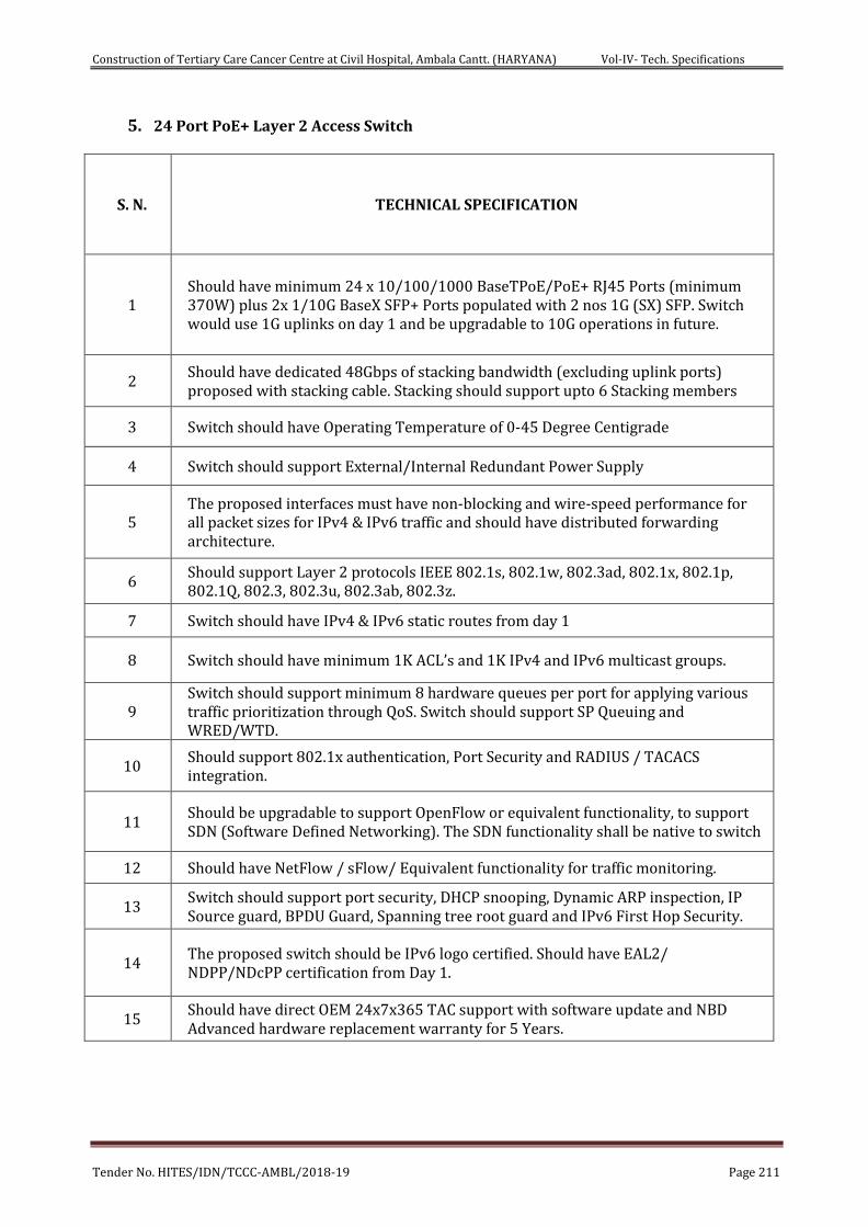
Construction of Tertiary Care Cancer Centre at Civil Hospital, Ambala Cantt. (HARYANA) Vol-IV- Tech. Specifications
Tender No. HITES/IDN/TCCC-AMBL/2018-19 Page 211
5. 24 Port PoE+ Layer 2 Access Switch
S. N. TECHNICAL SPECIFICATION
1 Should have minimum 24 x 10/100/1000 BaseTPoE/PoE+ RJ45 Ports (minimum 370W) plus 2x 1/10G BaseX SFP+ Ports populated with 2 nos 1G (SX) SFP. Switch would use 1G uplinks on day 1 and be upgradable to 10G operations in future.
2 Should have dedicated 48Gbps of stacking bandwidth (excluding uplink ports) proposed with stacking cable. Stacking should support upto 6 Stacking members
3 Switch should have Operating Temperature of 0-45 Degree Centigrade
4 Switch should support External/Internal Redundant Power Supply
5 The proposed interfaces must have non-blocking and wire-speed performance for all packet sizes for IPv4 & IPv6 traffic and should have distributed forwarding architecture.
6 Should support Layer 2 protocols IEEE 802.1s, 802.1w, 802.3ad, 802.1x, 802.1p, 802.1Q, 802.3, 802.3u, 802.3ab, 802.3z.
7 Switch should have IPv4 & IPv6 static routes from day 1
8 Switch should have minimum 1K ACL’s and 1K IPv4 and IPv6 multicast groups.
9 Switch should support minimum 8 hardware queues per port for applying various traffic prioritization through QoS. Switch should support SP Queuing and WRED/WTD.
10 Should support 802.1x authentication, Port Security and RADIUS / TACACS integration.
11 Should be upgradable to support OpenFlow or equivalent functionality, to support SDN (Software Defined Networking). The SDN functionality shall be native to switch
12 Should have NetFlow / sFlow/ Equivalent functionality for traffic monitoring.
13 Switch should support port security, DHCP snooping, Dynamic ARP inspection, IP Source guard, BPDU Guard, Spanning tree root guard and IPv6 First Hop Security.
14 The proposed switch should be IPv6 logo certified. Should have EAL2/ NDPP/NDcPP certification from Day 1.
15 Should have direct OEM 24x7x365 TAC support with software update and NBD Advanced hardware replacement warranty for 5 Years.
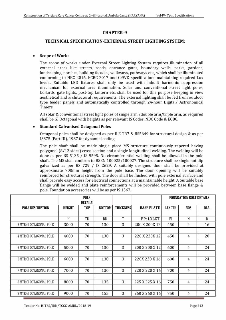
Construction of Tertiary Care Cancer Centre at Civil Hospital, Ambala Cantt. (HARYANA) Vol-IV- Tech. Specifications
Tender No. HITES/IDN/TCCC-AMBL/2018-19 Page 212
CHAPTER-9
TECHNICAL SPECIFICATION-EXTERNAL STREET LIGHTING SYSTEM:
Scope of Work:
The scope of works under External Street Lighting System requires illumination of all external areas like streets, roads, entrance gates, boundary walls, parks, gardens, landscaping, porches, building facades, walkways, pathways etc., which shall be illuminated conforming to NBC 2016, ECBC 2017 and CPWD specifications maintaining required Lux levels. Suitable LED fixtures shall only be used with inbuilt harmonic suppression mechanism for external area illumination. Solar and conventional street light poles, bollards, gate lights, post-top lantern etc. shall be used for this purpose keeping in view aesthetical and architectural requirements. The external lighting shall be fed from outdoor type feeder panels and automatically controlled through 24-hour Digital/ Astronomical Timers.
All solar & conventional street light poles of single arm /double arm/triple arm, as required shall be GI Octagonal with heights as per relevant IS Codes, NBC Code & ECBC.
Standard Galvanised Octagonal Poles
Octagonal poles shall be designed as per ILE TR7 & BS5649 for structural design & as per IS875 (Part III), 1987 for dynamic loading.
The pole shaft shall be made single piece MS structure continuously tapered having polygonal (8/12 sides) cross section and a single longitudinal welding. The welding will be done as per BS 5135 / IS 9595. No circumferential welding shall be allowed in the pole shaft. The MS shall conform to BSEN 100025/100027. The structure shall be single hot dip galvanized as per BS 729 / IS 2629. A suitably designed door shall be provided at approximate 700mm height from the pole base. The door opening will be suitably reinforced for structural strength. The door shall be flushed with pole external surface and shall provide easy access for electrical connections at a maintainable height. A Suitable base flange will be welded and plate reinforcements will be provided between base flange & pole. Foundation accessories will be as per IS 1367.
POLE DETAILS
FOUNDATION BOLT DETAILS
POLE DESCRIPTION HEIGHT TOP BOTTOM THICKNESS BASE PLATE LENGTH NOS DIA.
H TD BD T BP: LXLXT FL N D
3 MTR GI OCTAGONAL POLE 3000 70 130 3 200 X 200X 12 450 4 16
4 MTR GI OCTAGONAL POLE 4000 70 130 3 220 X 220X 12 450 4 20
5 MTR GI OCTAGONAL POLE 5000 70 130 3 200 X 200 X 12 600 4 24
6 MTR GI OCTAGONAL POLE 6000 70 130 3 220X 220 X 16 600 4 24
7 MTR GI OCTAGONAL POLE 7000 70 130 3 220 X 220 X 16 700 4 24
8 MTR GI OCTAGONAL POLE 8000 70 135 3 225 X 225 X 16 750 4 24
9 MTR GI OCTAGONAL POLE 9000 70 155 3 260 X 260 X 16 750 4 24
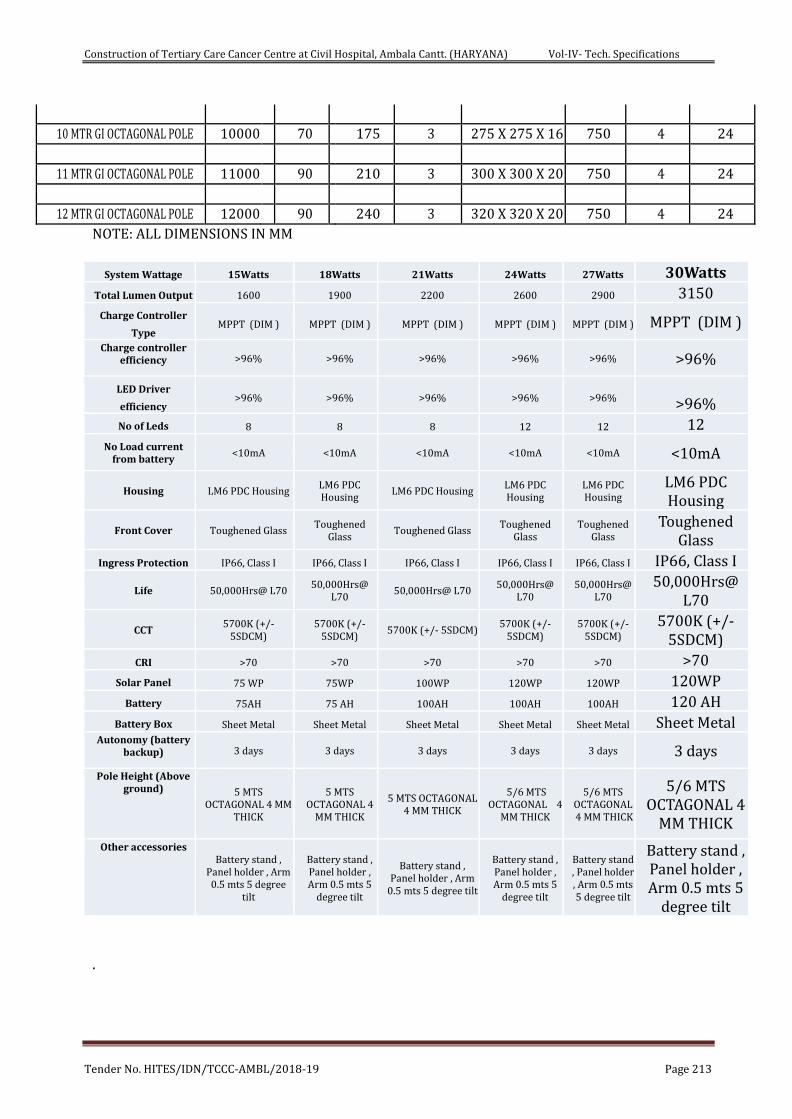
Construction of Tertiary Care Cancer Centre at Civil Hospital, Ambala Cantt. (HARYANA) Vol-IV- Tech. Specifications
Tender No. HITES/IDN/TCCC-AMBL/2018-19 Page 213
10 MTR GI OCTAGONAL POLE 10000 70 175 3 275 X 275 X 16 750 4 24
11 MTR GI OCTAGONAL POLE 11000 90 210 3 300 X 300 X 20 750 4 24
12 MTR GI OCTAGONAL POLE 12000 90 240 3 320 X 320 X 20 750 4 24
NOTE: ALL DIMENSIONS IN MM
System Wattage 15Watts 18Watts 21Watts 24Watts 27Watts 30Watts Total Lumen Output 1600 1900 2200 2600 2900 3150
Charge Controller
Type MPPT (DIM ) MPPT (DIM ) MPPT (DIM ) MPPT (DIM ) MPPT (DIM ) MPPT (DIM )
Charge controller efficiency >96% >96% >96% >96% >96% >96%
LED Driver
efficiency >96% >96% >96% >96% >96% >96%
No of Leds 8 8 8 12 12 12 No Load current
from battery <10mA <10mA <10mA <10mA <10mA <10mA
Housing LM6 PDC Housing LM6 PDC Housing
LM6 PDC Housing LM6 PDC Housing
LM6 PDC Housing
LM6 PDC Housing
Front Cover Toughened Glass Toughened
Glass Toughened Glass
Toughened Glass
Toughened Glass
Toughened Glass
Ingress Protection IP66, Class I IP66, Class I IP66, Class I IP66, Class I IP66, Class I IP66, Class I Life 50,000Hrs@ L70
50,000Hrs@ L70
50,000Hrs@ L70 50,000Hrs@
L70 50,000Hrs@
L70
50,000Hrs@ L70
CCT 5700K (+/-
5SDCM) 5700K (+/-
5SDCM) 5700K (+/- 5SDCM)
5700K (+/- 5SDCM)
5700K (+/- 5SDCM)
5700K (+/- 5SDCM)
CRI >70 >70 >70 >70 >70 >70 Solar Panel 75 WP 75WP 100WP 120WP 120WP 120WP
Battery 75AH 75 AH 100AH 100AH 100AH 120 AH Battery Box Sheet Metal Sheet Metal Sheet Metal Sheet Metal Sheet Metal Sheet Metal
Autonomy (battery backup) 3 days 3 days 3 days 3 days 3 days 3 days
Pole Height (Above ground) 5 MTS
OCTAGONAL 4 MM THICK
5 MTS OCTAGONAL 4
MM THICK
5 MTS OCTAGONAL 4 MM THICK
5/6 MTS OCTAGONAL 4
MM THICK
5/6 MTS OCTAGONAL 4 MM THICK
5/6 MTS OCTAGONAL 4
MM THICK Other accessories
Battery stand , Panel holder , Arm 0.5 mts 5 degree
tilt
Battery stand , Panel holder , Arm 0.5 mts 5
degree tilt
Battery stand , Panel holder , Arm
0.5 mts 5 degree tilt
Battery stand , Panel holder , Arm 0.5 mts 5
degree tilt
Battery stand , Panel holder , Arm 0.5 mts 5 degree tilt
Battery stand , Panel holder , Arm 0.5 mts 5
degree tilt .
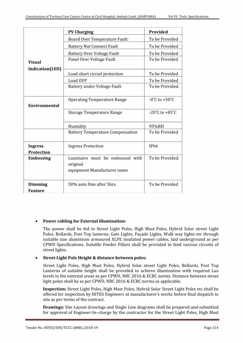
Construction of Tertiary Care Cancer Centre at Civil Hospital, Ambala Cantt. (HARYANA) Vol-IV- Tech. Specifications
Tender No. HITES/IDN/TCCC-AMBL/2018-19 Page 214
Power cabling for External illumination:
The power shall be fed to Street Light Poles, High Mast Poles, Hybrid Solar street Light Poles, Bollards, Post Top lanterns, Gate Lights, Façade Lights, Walk way lights etc through suitable size aluminium armoured XLPE insulated power cables, laid underground as per CPWD Specifications. Suitable Feeder Pillars shall be provided to feed various circuits of street lights.
Street Light Pole Height & distance between poles:
Street Light Poles, High Mast Poles, Hybrid Solar street Light Poles, Bollards, Post Top Lanterns of suitable height shall be provided to achieve illumination with required Lux levels in the external areas as per CPWD, NBC 2016 & ECBC norms. Distance between street light poles shall be as per CPWD, NBC 2016 & ECBC norms as applicable.
Inspection: Street Light Poles, High Mast Poles, Hybrid Solar Street Light Poles etc shall be offered for inspection by HITES Engineers at manufacturer’s works before final dispatch to site as per terms of the contract.
Drawings: Site Layout drawings and Single Line diagrams shall be prepared and submitted for approval of Engineer-In–charge by the contractor for the Street Light Poles, High Mast
Visual
Indication(LED)
PV Charging Provided Board Over Temperature Fault: To be Provided Battery Not Connect Fault To be Provided Battery Over Voltage Fault To be Provided Panel Over Voltage Fault To be Provided
Load short circuit protection To be Provided Load OVP To be Provided Battery under Voltage Fault To be Provided.
Environmental
Operating Temperature Range -0˚C to +50˚C
Storage Temperature Range -20˚C to +85˚C
Humidity 95%RH Battery Temperature Compensation
To be Provided
Ingress
Protection Ingress Protection IP66
Embossing Luminaire must be embossed with
original
equipment Manufacturer name
To be Provided.
Dimming
Feature 50% auto Dim after 5hrs. To be Provided
Construction of Tertiary Care Cancer Centre at Civil Hospital, Ambala Cantt. (HARYANA) Vol-IV- Tech. Specifications
Tender No. HITES/IDN/TCCC-AMBL/2018-19 Page 215
Poles, Hybrid Solar street Light Poles, Bollards, Post Top lanterns, Gate Lights, Façade Lights, Walk Way lights etc. The drawings shall be got approved from Engineer-In–charge before commencement of works at site.
Applicable IEC Standards:
i. IEC 61215 latest: Solar Panel
ii. IEC 61347-2-13 : LED driver safety
iii. IEC 62384 : LED driver performance
iv. CISPR 15 : Radio disturbance characteristics
v. IEC 61547 : EMC immunity requirements
vi. IEC 60598 : General requirements and test
Construction of Tertiary Care Cancer Centre at Civil Hospital, Ambala Cantt. (HARYANA) Vol-IV- Tech. Specifications
Tender No. HITES/IDN/TCCC-AMBL/2018-19 Page 216
CHAPTER - 10
UPS SYSTEM
Quality power Supply
The UPS shall be ON-LINE double conversion with filter, stabilized and reliable
voltage that is free from all mains interference (Over voltage, frequency variations,
voltage drops).
The battery bank should have provision for future expansions. The UPS shall have
Optional filters, Isolation transformer module, LCD-based remote control panel etc.
The Operating mode of UPS
It should operate in following on-line operating mode:
Economy Mode: The UPS should use Line Interactive technology, i.e. the load is
powered from the mains; the energy consumption is reduced with a subsequent
improvement in efficiency .
Smart active mode: The UPS should automatically selects On Line or Line
Interactive operating mode according to the quality of the mains supply, by
monitoring the number, frequency and type of disturbances at the mains power
input.
Stand-by-off mode: With the mains available the UPS should normally not
powered and consequently the power consumption is almost nil. Only when the
mains fails or falls outside a preset range, does the inverter take over using power
from the batteries. This mode shall be suitable for Emergency escape lighting as pr
standard EN 50171.
The UPS shall have Expandable feature. The UPS shall have expandable feature to
increase power availability or redundancy. For the expandability there shall be “Hot
System Expansion” feature, the additional unit can be connected in parallel while
the other units are on-line and supplying regular power to the load.
Maximum safety for personnel
There should be a feedback protection device in the UPS to prevent any voltage
back feed in the upstream distribution board, thus ensuring the maintenance
personal.
For Advanced communication there shall be software system which displays the
most important information such as the input and output Voltage, the load applied,
the remaining back-up time, etc. It should also be able to provide information even
in the event of a failure, to support the fault diagnostics.
It should also contain the following hardware interfaces:
RS232 serial port
Dry contacts
EPO (Emergency Power Off)
Contact for UPS shutdown using the remote emergency button.
Construction of Tertiary Care Cancer Centre at Civil Hospital, Ambala Cantt. (HARYANA) Vol-IV- Tech. Specifications
Tender No. HITES/IDN/TCCC-AMBL/2018-19 Page 217
The UPS should have Mimic Panel for status and alarm, control and commands,
input, output, battery status and settings.
Low Input Harmonic Distortion
The UPS shall have The Power Factor Correction (PFC), standard on all modules, so
that the input power factor level to 0.95 for any load percentages so that it is ideal
in conjunction with motor generator or in installation with other sensitive loads.
There shall be built in Active Filter designed to reduce the level of THDi to less than
4% and to increase the input power factor up to 0.99.
This Active filter shall be based on the IGBT’s Technologies controlled by the Digital
Signal Processor (DSP). This DSP instantly monitors and controls the inputs current
absorbed by the UPS in order to eliminate the unlike harmonics and maintain the
THDi less than 4%. With the effect of Active Filter the UPS can also be connected to
the low loads. These active filters shall be fitted inside the UPS so that no additional
footprint is required.
UPS & its features:-
The input requirements of the UPS are as follows:
Voltage : 400 V three-phase + Neutral
Voltage tolerance : ± 20%+
Frequency : 45-65 Hz
Current distortion : <4% with active filter
Power factor : 0.99 with active filter
The Bypass of the UPS are as follows:
Rated voltage : 400 V three-phase + N
Phases number : 3 + N
Voltage tolerance : ± 15%
Rated frequency : 50 Hz
Frequency tolerance : ± 2%
By-pass : Staticand manual for maintenance
Transfer time : Nil
The Battery for the UPS are as follows:
Type of battery : maintenance-free sealed leadacid
Battery blocks : 12 V
Recharge time minimum : 6 Hr
The Output of UPS are as follows:
Construction of Tertiary Care Cancer Centre at Civil Hospital, Ambala Cantt. (HARYANA) Vol-IV- Tech. Specifications
Tender No. HITES/IDN/TCCC-AMBL/2018-19 Page 218
Rated power : Asper General arrangement/DBR
Active power : Asper General
arrangement/DBR
Phases number : 3 + N
Waveform : Sinewave
Rated voltage : 415V
Frequency : 50 Hz
Dynamic stability : ± 5%0.
Static stability : ± 1% 00
Crest factor : 3 : 1
Overload : 110% for 5Min, 125% for 10 min, 150 for 1Min
The System of UPS is as follows:
AC/AC efficiency : 92% in On-line mode
Noise : 50-56 Db at 1 M distance
Operating temperature : -2º - 45ºC
Relative humidity : 95% non-condensing
Remote controls : EPO & Bypass
Remote signals : volt free contacts
Protection degree : IP20
Communication : Double RS232/C + slot for SNMP
Adapter
The Standard of UPS are as follows:
i. Safety EN 62040-1
ii. EMC IEC 62040-2
iii. EN 50091-2 lev. A
iv. Directives 73/23, 93/68, 89/336 EEC
v. EN 62040-3.
All Outlets for power in IT room, Audio-visual media room, EPABX room,
Fire Officer Control Room & Security room shall be fed from UPS supply
Construction of Tertiary Care Cancer Centre at Civil Hospital, Ambala Cantt. (HARYANA) Vol-IV- Tech. Specifications
Tender No. HITES/IDN/TCCC-AMBL/2018-19 Page 219
CHAPTER - 11
TECHNICAL SPECIFICATIONS - FIRE ALARM SYSTEM
GENERAL
A. The specifications includes furnishing, installation, connection and testing of the microprocessor controlled, intelligent reporting fire alarm network equipment required to form a complete, operative, coordinated system. It shall include, but not be limited to, alarm initiating devices, alarm notification appliances, Network Fire Alarm Control Panels (FACP), Network Reporting Terminals (NRT), Network Liquid Crystal Display (NLCD), auxiliary control devices, annunciators, and wiring as shown on the drawings and specified herein.
B. The fire alarm system shall comply with requirements of IS:2189:1999 & 1996 NFPA Standard 72 for Protected Premises Signaling Systems except as modified and supplemented by this specification, or the stringent one of the two specification in case of any discrepancy. The system shall be electrically supervised and monitor the integrity of all conductors.
C. Fire Alarm System shall be integrated with P.A. system. A digitized pre-recorded voice message shall notify occupants that a fire condition has been reported. The message shall instruct the occupants with emergency instructions. Emergency manual voice override shall be provided.
D. The system and its components shall be Underwriters Laboratories, Inc. listed under the appropriate UL testing standard as listed herein for fire alarm applications and shall be in compliance with the UL listing
E. Each designated zone shall transmit separate and different alarm, supervisory and trouble signals to the Fire Alarm Control Room and designated personnel.
F. The FACPs shall be active/interrogative-type systems where each transponder is repetitively scanned, causing a signal to be transmitted to the fire alarm control panel node indicating that the transponder and its associated initiating device and notification appliance circuit wiring is functional. Loss of this signal at the FACP shall result in a trouble indication on both the FACP display and at the network display, as specified hereinafter for the particular input.
G. The system shall be arranged such that not less than 20 percent additional transponders may be inserted into any network communication loop.
H. The installing company shall employ technicians on site to guide the labours and to ensure the systems integrity.
SCOPE:
A new network intelligent reporting, microprocessor controlled fire detection and shall be compatible with PA system emergency voice alarm communication network shall be installed in accordance with the specifications and drawings.
Basic Performance:
A. Alarm and trouble signals from the FACP, NRT, and NLCD network nodes shall be digitally encoded by listed electronic devices onto a NFPA Style 9 looped multiplex communication system.
Construction of Tertiary Care Cancer Centre at Civil Hospital, Ambala Cantt. (HARYANA) Vol-IV- Tech. Specifications
Tender No. HITES/IDN/TCCC-AMBL/2018-19 Page 220
B. Alarm, trouble and supervisory signals from all intelligent reporting devices shall be encoded onto NFPA Style 6 (Class A) Signaling Line Circuits (SLC).
C. Initiation Device Circuits (IDC) shall be wired Class A (NFPA Style D). Connected by the SLC.
D. Notification Appliance Circuits (NAC) shall be wired Class A (NFPA Style Z). Connected by the SLC.
E. Power for initiating devices and notification appliances must be from the main fire alarm control panel, the transponder to which they are connected or to a Field Charging Power Supply (FCPS).
F. A single ground or open on any system signaling line circuit, initiating device circuit, or notification appliance circuit shall not cause system malfunction, loss of operating power or the ability to report an alarm.
G. Alarm signals arriving at the main FACP shall not be lost following a power failure (or outage) until the alarm signal is processed and recorded.
H. Digitized electronic signals shall employ check digits or multiple polling.
I. Transponder devices are to consist of low current, solid-state integrated circuits, and shall be powered locally from a primary power and standby power source.
J. F.A. System shall be integrated with P.A system & Car Calling system so that it can be used for Emergency evacuation under fire condition.
SUBMITTALS
A. General:
All substitute equipment proposed as equal to the equipment specified herein, shall meet or exceed the following standards. For equipment other than that specified, the contractor shall supply proof that such substitute equipment does in fact equal or exceed the features, functions, performance, and quality of the specified equipment. Two copies of all submittals shall be submitted to the Engineer-in-charge/Engineer for review.
B.Shop Drawings:
1. Sufficient information, clearly presented, shall be included to determine compliance with drawings and specifications.
2. Include manufacturer's name(s), model numbers, ratings, power requirements, equipment layout, device arrangement, complete wiring point-to-point diagrams, and conduit layouts.
3. Show equipment layout and main control panel, module layout, configurations and terminations.
C.Manuals:
Submit simultaneously with the shop drawings, complete operating and maintenance manuals listing the manufacturer's name(s) including technical data sheets.
Wiring diagrams shall indicate internal wiring for each item of equipment and the interconnections between the items of equipment.
Provide a clear and concise description of operation, which gives the information required to properly operate the equipment and system.
Approvals will be based on complete submissions of manuals together with shop drawings.
D. Software Modifications
Construction of Tertiary Care Cancer Centre at Civil Hospital, Ambala Cantt. (HARYANA) Vol-IV- Tech. Specifications
Tender No. HITES/IDN/TCCC-AMBL/2018-19 Page 221
Provide the services of a factory trained and authorized technician to perform all system software modifications, upgrades or changes. Response time of the technician to the site shall not exceed 2 hours.
Provide all hardware, software, programming tools and documentation necessary to modify the fire alarm network on site. Modification includes addition and deletion of devices, circuits, zones and changes to system operation and custom label changes for devices or zones. The system structure and software shall place no limit on the type or extent of software modifications on-site. Modification of software shall not require power-down of the system or loss of system fire protection while modifications are being made.
E. Certifications:
Together with the shop drawing submittal, submit a certification from the major equipment manufacturer indicating that the proposed supervisor of installation and the proposed performer of contract maintenance is an authorized representative of the major equipment manufacturer and trained on network applications. Include names and addresses in the certification.
APPLICABLE PUBLICATIONS:
The publications listed below form a part of this specification. The publications are referenced in text by the basic designation only.
A. The fire alarm system shall comply with requirements of NFPA for protected premises signaling systems except as modified and supplemented by this specification. The system field wiring shall be supervised either electrically or by software-directed polling of field devices.
B. Underwriters Laboratories Inc. (UL) - USA:
C. Local and State Building Codes.
D. All requirements of the Authority Having Jurisdiction (AHJ).
APPROVALS:
A. The system must have proper listing and/or approval from the following nationally recognized agencies:
UL Underwriters Laboratories Inc
FM Factory Manual
ULC Underwriters Laboratories Canada
CPWD Central Public Work Department
BIS Bureau of Indian Standards
B. The fire alarm control panel, network interface and all transponders shall meet the modular labeling requirements of Underwriters Laboratories, Inc. Each subassembly, including all printed circuits, shall include the appropriate UL modular label. Systems which do not include modular labels, which may require return to the manufacturer for system upgrades, and are not acceptable.
PRODUCTS
EQUIPMENT AND MATERIAL, GENERAL:
A. All equipment and components shall be new, and the manufacturer's current model. The materials, appliances, equipment and devices shall be tested and listed by a nationally recognized approvals agency for use as part of a protected premises
Construction of Tertiary Care Cancer Centre at Civil Hospital, Ambala Cantt. (HARYANA) Vol-IV- Tech. Specifications
Tender No. HITES/IDN/TCCC-AMBL/2018-19 Page 222
protective signaling (fire alarm) system. The authorized representative of the manufacturer of the major equipment, such as control panels, shall be responsible for the satisfactory installation of the complete system.
B. All equipment and components shall be installed in strict compliance with each manufacturer's recommendations. Consult the manufacturer's installation manuals for all wiring diagrams, schematics, physical equipment sizes, etc. before beginning system installation. Refer to the riser/connection diagram for all specific system installation/termination/wiring data.
C. All equipment shall be attached to walls and ceiling/floor assemblies and shall be held firmly in place. (e.g., detectors shall not be supported solely by suspended ceilings). Fasteners and supports shall be adequate to support the required load.
CONDUIT AND WIRE:
A. M.S. Conduit:
1. Conduit shall be in accordance with the National Electrical Code (NEC), local and state requirements.
2. Where possible, all wiring shall be installed in conduit or raceway. Conduit fill shall not exceed 40 percent of interior cross sectional area where three or more cables are contained within a single conduit.
3. Cable must be separated from any open conductors of power, or Class 1 circuits, and shall not be placed in any conduit, junction box or raceway containing these conductors, per NEC Article 760-29.
4. Wiring for 24 volt control, alarm notification, emergency communication and similar power-limited auxiliary functions may be run in the same conduit as initiating and signaling line circuits. All circuits shall be provided with transient suppression devices and the system shall be designed to permit simultaneous operation of all circuits without interference or loss of signals.
5. Conduit shall not enter any FACP or any other remotely mounted control panel equipment or back boxes, except where conduit entry is specified by the FACP manufacturer.
The following specifications of Maharashtra Schedule of Rates shall be followed:-
1. WGMA/BW
Scope
Concealing of Rigid steel Conduits:
In walls / flooring:
Concealing of Rigid steel conduits and erecting in wall, flooring by making chases / grooves/ entries as per approved Method of Construction along with continuous earth wire and all required material including earth clips hardware such as ‘U’ nails, binding wire, fish wire; accessories such as MS junction / inspection boxes, check-nuts, flexible PVC pipe, drawing fish wires and making all piping rigid, refinishing the surface with cement mortar, removing debris from site.
Material:
Rigid Steel Conduits:
Rigid steel HG conduit minimum 20mm dia and 16 gauge, ERW grade duly processed for antirust treatment and painted with black enamel paint, accessories for rigid steel conduits
Construction of Tertiary Care Cancer Centre at Civil Hospital, Ambala Cantt. (HARYANA) Vol-IV- Tech. Specifications
Tender No. HITES/IDN/TCCC-AMBL/2018-19 Page 223
such as check nuts, long bends, deep junction boxers for flooring, regular junction boxes for walls; of required ways all of the same make.
Construction of Tertiary Care Cancer Centre at Civil Hospital, Ambala Cantt. (HARYANA) Vol-IV- Tech. Specifications
Tender No. HITES/IDN/TCCC-AMBL/2018-19 Page 224
Earth continuity wire:
GI wire of 2.5 sq. mm GI earth clips 22 gauge, 100 mm width, for fixing earth wire along the conduits.
Junction boxes / Draw – in boxes:
Junction box shall be 5 sided with removable to plate and of suitable size to accommodate No. of entries; fabricated from 16 SWG CRCA sheet steel earth terminal duly treated with antirust treatment and painted with two coats of red oxide paint. There shall be knock out holes in required numbers and dia for entry of conduit of conduit pipes and arrangement to fix cover plates on it.
Hardware:
‘U’ nails, plumbing and general use nails of required sizes, washers, check-nuts, steel binding wire 20 gauge, GI fish wire, etc.
Method of Construction:
Concealing of Rigid Steel conduits:
General:
Work shall be done in co-ordination with civil work to suit final approved layout. Size of conduit shall be correct depending on number of wires to be drawn. (Table No. 1/1, for Steel conduits) Separate pipe shall be used for each phase in 1-ph distribution and for power and light distribution and also for wiring for other utilities like data, telephone, TV cabling, etc; for which the distance between pipes shall not be less than 300 mm or anti electrostatic partition is to be provided. Adequate use of conduit accessories shall be made at required locations. Entries in wall shall be at level of corresponding conduit with colour coding as per Table No. 1 / 4(For Visual identification) Flexible conduits shall be used at expansion joints. Erection shall be done as per the layout finalized with minimum sharp bends, with junction boxes at angular junctions and for straight runs at every 4.25 metre; in such manner so as to facilitate drawing of wires. All bending of conduits shall be done approved manner without changing the cross-section.
Concealing of Rigid Steel Conduits in walls/ flooring:
Chases shall be made in walls of adequate width with cutter and chiseling through it. Necessary finishing of the wall surface shall be done. Work in flooring shall not disturb RCC work, Conduits of adequate size shall be erected with use of appropriate accessories, and hardware like ‘U’ nails, etc. draw-in / inspection boxes shall be fixed with check-nut, flush with surrounding surface and earthed.
Testing:
Earth continuity:
Earth continuity shall be ensured at termination point of Earth wire, between the ends of metal conduit.
Mode of Measurement:
Measurement shall be carried out on the basis per running meter length of conduit.
a) WGMA/CC-
Scope:
Bunch of wires:
Providing specified wires and drawing them through provided conduits/ trunking and / or as directed with coated ferrules, harnessing the bunch of wires with necessary material when
Construction of Tertiary Care Cancer Centre at Civil Hospital, Ambala Cantt. (HARYANA) Vol-IV- Tech. Specifications
Tender No. HITES/IDN/TCCC-AMBL/2018-19 Page 225
used in panel boards, duly connecting / terminating with lugs, and testing for safety and beneficial use.
Material:
Wires: in conduits/ trunking/ panel boards
Mains/ Sub- Main/ Circuit mains (comprising phase and neutral wires):
PVC insulated wire of specified size, minimum FR Grade insulation copper conductor of electrolytic tough pitch (ETP) grade having insulation of 1.1 kV grade, ISI marked of required colour coding as per Table No. 1/5.
Wires: Open
PVC insulated and PVC sheathed wire of specified size, minimum FR Grade insulation, copper conductor of electrolytic tough pitch (ETP) grade, having insulation of 1.1 kV grade, ISI marked of required colour coding as per Table No. 1/5.
Earth Continuity wire:
PVC insulated wire minimum FR Grade insulation, copper conductor of electrolytic grade, having insulation of 1.1 kV grade of green/ green yellow colour, ISI marked of required colour coding as per Table No. 1/5.
Lugs:
Copper lugs of appropriate size & type.
Other material:
Rubber grommet, bush, harnessing material, flexible conduit etc.
Method of Construction:
Bunch of wires:
Drawing of wires: General
Specified wires shall be drawn with adequate care. Correct colour coding as per Table No. 1/5 shall be used for phase, neutral and earth. Wires shall not have intermediate joint in between terminals of the accessories. Earth-wire and Return wire (neutral) of two different phases, shall not be drawn in single pipe. Wires shall be terminated in the terminals of accessories only, with appropriate type of size and lugs.
Drawing of wires: through PVC conduits.
Bush shall be used at pipe opening to protect wire insulation from getting damaged due to burrs/ sharp edges. Number of wires shall not exceed with respect to size of pipe as per Table No. 1/2.
Drawing of wires: through Rigid Steel conduits
Bush shall be used at pipe opening to protect wire insulation from getting damaged due to burrs/ sharp edges. Number of wires shall not exceed with respect to size of pipe as per Table No. 1/1.
Open wire bunch:
Open wires shall be erected with due care so as to avoid chances of any mechanical manner in panel boards or where ever necessary. For covering lead wires flexible conduit shall be used with gland as per necessity.
Testing:
Insulation resistance test:
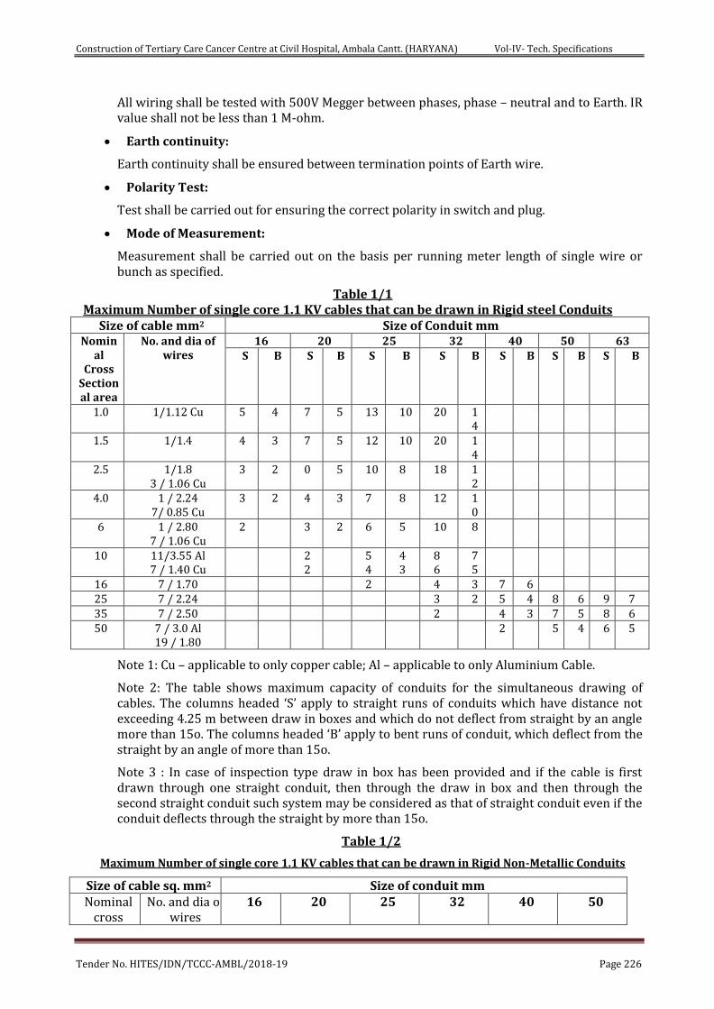
Construction of Tertiary Care Cancer Centre at Civil Hospital, Ambala Cantt. (HARYANA) Vol-IV- Tech. Specifications
Tender No. HITES/IDN/TCCC-AMBL/2018-19 Page 226
All wiring shall be tested with 500V Megger between phases, phase – neutral and to Earth. IR value shall not be less than 1 M-ohm.
Earth continuity:
Earth continuity shall be ensured between termination points of Earth wire.
Polarity Test:
Test shall be carried out for ensuring the correct polarity in switch and plug.
Mode of Measurement:
Measurement shall be carried out on the basis per running meter length of single wire or bunch as specified.
Table 1/1 Maximum Number of single core 1.1 KV cables that can be drawn in Rigid steel Conduits
Size of cable mm2 Size of Conduit mm Nomin
al Cross
Sectional area
No. and dia of wires
16 20 25 32 40 50 63 S B S B S B S B S B S B S B
1.0 1/1.12 Cu 5 4 7 5 13 10 20 14
1.5 1/1.4 4 3 7 5 12 10 20 14
2.5 1/1.8 3 / 1.06 Cu
3 2 0 5 10 8 18 12
4.0 1 / 2.24 7/ 0.85 Cu
3 2 4 3 7 8 12 10
6 1 / 2.80 7 / 1.06 Cu
2 3 2 6 5 10 8
10 11/3.55 Al 7 / 1.40 Cu
2 2
5 4
4 3
8 6
7 5
16 7 / 1.70 2 4 3 7 6 25 7 / 2.24 3 2 5 4 8 6 9 7 35 7 / 2.50 2 4 3 7 5 8 6 50 7 / 3.0 Al
19 / 1.80 2 5 4 6 5
Note 1: Cu – applicable to only copper cable; Al – applicable to only Aluminium Cable.
Note 2: The table shows maximum capacity of conduits for the simultaneous drawing of cables. The columns headed ‘S’ apply to straight runs of conduits which have distance not exceeding 4.25 m between draw in boxes and which do not deflect from straight by an angle more than 15o. The columns headed ‘B’ apply to bent runs of conduit, which deflect from the straight by an angle of more than 15o.
Note 3 : In case of inspection type draw in box has been provided and if the cable is first drawn through one straight conduit, then through the draw in box and then through the second straight conduit such system may be considered as that of straight conduit even if the conduit deflects through the straight by more than 15o.
Table 1/2
Maximum Number of single core 1.1 KV cables that can be drawn in Rigid Non-Metallic Conduits
Size of cable sq. mm2 Size of conduit mm Nominal
cross No. and dia of
wires 16 20 25 32 40 50
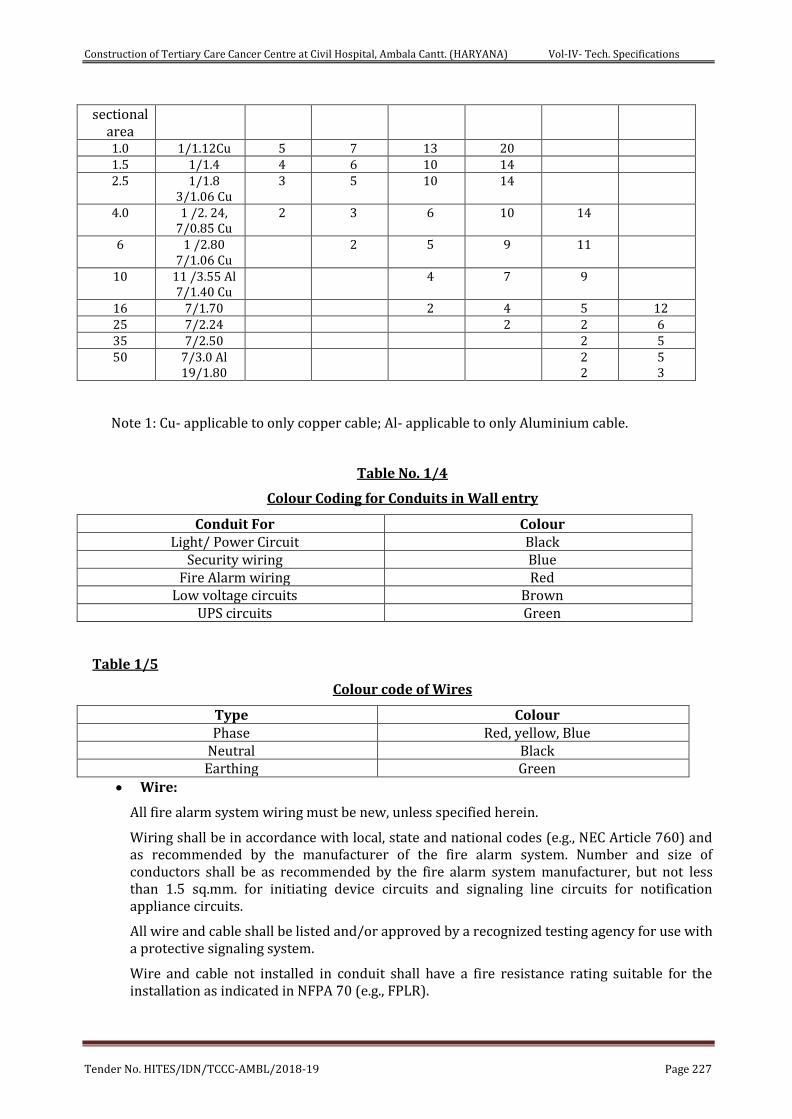
Construction of Tertiary Care Cancer Centre at Civil Hospital, Ambala Cantt. (HARYANA) Vol-IV- Tech. Specifications
Tender No. HITES/IDN/TCCC-AMBL/2018-19 Page 227
sectional area 1.0 1/1.12Cu 5 7 13 20 1.5 1/1.4 4 6 10 14 2.5 1/1.8
3/1.06 Cu 3 5
10 14
4.0 1 /2. 24, 7/0.85 Cu
2 3 6 10 14
6 1 /2.80 7/1.06 Cu
2 5 9 11
10 11 /3.55 Al 7/1.40 Cu
4 7 9
16 7/1.70 2 4 5 12 25 7/2.24 2 2 6 35 7/2.50 2 5 50 7/3.0 Al
19/1.80 2
2 5 3
Note 1: Cu- applicable to only copper cable; Al- applicable to only Aluminium cable.
Table No. 1/4
Colour Coding for Conduits in Wall entry
Conduit For Colour Light/ Power Circuit Black
Security wiring Blue Fire Alarm wiring Red
Low voltage circuits Brown UPS circuits Green
Table 1/5
Colour code of Wires
Type Colour Phase Red, yellow, Blue
Neutral Black Earthing Green
Wire:
All fire alarm system wiring must be new, unless specified herein.
Wiring shall be in accordance with local, state and national codes (e.g., NEC Article 760) and as recommended by the manufacturer of the fire alarm system. Number and size of conductors shall be as recommended by the fire alarm system manufacturer, but not less than 1.5 sq.mm. for initiating device circuits and signaling line circuits for notification appliance circuits.
All wire and cable shall be listed and/or approved by a recognized testing agency for use with a protective signaling system.
Wire and cable not installed in conduit shall have a fire resistance rating suitable for the installation as indicated in NFPA 70 (e.g., FPLR).
Construction of Tertiary Care Cancer Centre at Civil Hospital, Ambala Cantt. (HARYANA) Vol-IV- Tech. Specifications
Tender No. HITES/IDN/TCCC-AMBL/2018-19 Page 228
Wiring used for the signaling line circuit (SLC) shall be twisted and shielded and installed in conduit unless specifically accepted by the fire alarm equipment manufacturer.
All field wiring shall be completely supervised.
FIRE ALARM CONTROL PANELS AND FIRE CONTROL ROOM:
The Fire Alarm Control Panel shall be as per Section 7.33 of IS: 2189.
Each network FACP shall contain a microprocessor-based central processing unit (CPU). The CPU shall communicate with and control the following types of equipment used to make up the system: intelligent addressable detectors, addressable modules, Panel modules including initiating circuit, control circuits, transponders, local and remote operator terminals, printers, annunciators, emergency voice communication systems, and other system controlled devices.
Each FACP on the network shall perform the following functions:
1. It shall Supervise and monitor all intelligent addressable detectors and monitor modules connected to the system for normal, trouble and alarm conditions.
2. It shall supervise all initiating signaling and notification circuits throughout the facility by way of connection to monitor and control modules.
3. It shall detect the activation of any initiating device and the location of the alarm condition. Operate all notification appliances and auxiliary devices as programmed. In the event of CPU failure, all SLC loop modules shall fallback to degrade mode. Such degrade mode shall treat the corresponding SLC loop control modules and associated detection as conventional two-wire operation. Any activation of a detector in this mode shall automatically activate associated Notification Appliance Circuits.
4. It shall visually and audibly annunciate any trouble, supervisory, security or alarm condition on operator’s terminals, panel display, and annunciators.
5. When a any of the following condition is detected and reported by one of the system initiating devices or appliances:
i. Fire Alarm Conduits
ii. Trouble Confirmation
iii. Supervisory Card
iv. Security Alarm
v. Pre Alarm
Then the following functions shall immediately occur:
a. The FACP alarm LED on the FACP shall flash.
b. A local piezo-electric indication for the event signal for the event in the FACP shall sound a distinctive Signal.
c. The 960(24X40)-character LCD display on the local FACP node and on the network displays shall indicate all information associated with the fire alarm condition, including the type of alarm point, and its location within the protected premises. This information shall also be displayed on the network reporting terminal.System can be configured without taking the panel offline and shall have the feature of Remote diagnostics via a built-in web server.
d. Printing and 12000 history storage equipment shall log the information associated with the fire alarm control panel condition, along with the time and date of
Construction of Tertiary Care Cancer Centre at Civil Hospital, Ambala Cantt. (HARYANA) Vol-IV- Tech. Specifications
Tender No. HITES/IDN/TCCC-AMBL/2018-19 Page 229
occurrence. The Panel should have Built-in Ethernet Port for Webserver, BACnet and 3D color graphics software.
e. All system output programs assigned via control-by-event interlock programming to be activated by the particular point in alarm shall be executed, and the associated system outputs (alarm notification appliances and/or relays) shall be activated on either local outputs or points located on other network nodes.
General FACP Configuration & Operation:
1. Each FACP node shall include a full featured operator interface control and annunciation panel which shall include a backlit 960(24X40) character Liquid Crystal Display (LCD), individual, color coded system status LEDs, and an alpha-numeric keypad for field programming and control of the node.
2. All programming or editing of the existing programming in the system shall be achieved without special equipment or interrupting the alarm monitoring functions of the fire alarm control panel.
3. FACP nodes shall be designed so that it permits continued local operation of remote transponders under both normal and abnormal network communication loop conditions. This shall be obtained by having transponders operate as local control panels upon loss of network communication.
4. FACP nodes shall be modular in construction to allow ease of servicing. Each CPU and transponder shall be capable of being programmed on site without requiring the use of any external programming equipment. Systems which require use of external programmers or change of EPROMs are not acceptable.
5. The CPU and associated equipment are to be protected so that they will not be affected by voltage surges or line transients including RFI and EMI.
6. Each transponder and peripheral device connected to the FACP node CPU shall be continuously scanned for proper operation. Data transmissions between network nodes, FACP CPUs, transponders, and peripheral devices shall be reliable and error free. The transmission scheme used shall employ dual transmission or other equivalent error checking techniques. Failure of any transponder or peripheral device to respond to an interrogation shall be annunciated as a trouble condition.
The FACP shall be able to provide the following software and hardware features:
1. Pre- Signal and Positive Alarm Sequence: The system shall provide means to cause pre-alarm signals to only sound in specific areas with a delay of the alarm from 60 to up to 180 seconds after start of alarm processing. In addition, a Positive Alarm Sequence selection shall be available that allows a 15-Second time period for acknowledge an alarm signal from a fire detection/initiating device. If the alarm is not acknowledged within 15 seconds, all local remote outputs shall automatically immediately.
2. Smoke Detector Pre-Alarm indication at control panel: To obtain early warning of incipient or potential fire conditions, the system shall support a programmable option to determine system response to real-time detector sensing values above the programmed setting. Two levels of Pre-Alarm indication shall be available at the control.
a) Alert: It shall be possible to set individual smoke detectors for pre-programmed pre-alarm thresholds. If the individual threshold is reached, the pre-alarm condition shall be activated.
b) Action: if programmed for action and the detector reaches a level exceeding the pre-programmed level, the control panel shall indicate an action
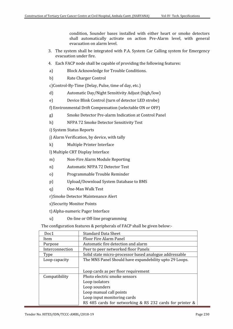
Construction of Tertiary Care Cancer Centre at Civil Hospital, Ambala Cantt. (HARYANA) Vol-IV- Tech. Specifications
Tender No. HITES/IDN/TCCC-AMBL/2018-19 Page 230
condition, Sounder bases installed with either heart or smoke detectors shall automatically activate on action Pre-Alarm level, with general evacuation on alarm level.
3. The system shall be integrated with P.A. System Car Calling system for Emergency evacuation under fire.
4. Each FACP node shall be capable of providing the following features:
a) Block Acknowledge for Trouble Conditions.
b) Rate Charger Control
c) Control-By-Time (Delay, Pulse, time of day, etc.)
d) Automatic Day/Night Sensitivity Adjust (high/low)
e) Device Blink Control (turn of detector LED strobe)
f) Environmental Drift Compensation (selectable ON or OFF)
g) Smoke Detector Pre-alarm Indication at Control Panel
h) NFPA 72 Smoke Detector Sensitivity Test
i) System Status Reports
j) Alarm Verification, by device, with tally
k) Multiple Printer Interface
l) Multiple CRT Display Interface
m) Non-Fire Alarm Module Reporting
n) Automatic NFPA 72 Detector Test
o) Programmable Trouble Reminder
p) Upload/Download System Database to BMS
q) One-Man Walk Test
r) Smoke Detector Maintenance Alert
s) Security Monitor Points
t) Alpha-numeric Pager Interface
u) On-line or Off-line programming
The configuration features & peripherals of FACP shall be given below:-
Doc1 Standard Data Sheet Item Floor Fire Alarm Panel Purpose Automatic fire detection and alarm Interconnection Peer to peer networked floor Panels Type Solid state micro-processor based analogue addressable Loop capacity The MNS Panel Should have expandebility upto 29 Loops.
Loop cards as per floor requirement Compatibility Photo electric smoke sensors
Loop isolators Loop sounders Loop manual call points Loop input monitoring cards RS 485 cards for networking & RS 232 cards for printer &
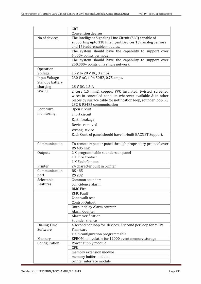
Construction of Tertiary Care Cancer Centre at Civil Hospital, Ambala Cantt. (HARYANA) Vol-IV- Tech. Specifications
Tender No. HITES/IDN/TCCC-AMBL/2018-19 Page 231
CRT Convention devises
No of devices The Intelligent Signaling Line Circuit (SLC) capable of supporting upto 318 Intelligent Devices 159 analog Sensors and 159 addressable modules.
The system should have the capability to support over 5,000+ points per node.
The system should have the capability to support over 250,000+ points on a single network.
Operation Voltage 15 V to 28 V DC, 3 amps Input Voltage 230 V AC, 1 Ph 50HZ, 0.75 amps. Standby battery charging 28 V DC, 1.5 A Wiring 2 core 1.5 mm2, copper, PVC insulated, twisted, screened
wires in concealed conduits wherever available & in other places by surface cable for notification loop, sounder loop, RS 232 & RS485 communication
Loop wire monitoring
Open circuit
Short circuit
Earth Leakage
Device removed
Wrong Device Each Control panel should have In-built BACNET Support.
Communication To remote repeater panel through proprietary protocol over
RS 485 link Outputs 2 X programmable sounders on panel
1 X Fire Contact 1 X Fault Contact
Printer 24 character built in printer Communication port
RS 485 RS 232
Selectable Features
Common sounders coincidence alarm RMC Fire
RMC Fault Zone walk test Control Output Output delay Alarm counter Alarm Counter Alarm verification Sounder silence
Dialing Time 4 second per loop for devices, 3 second per loop for MCPs Software Firmware
Field configuration programmable Memory EPROM non volatile for 12000 event memory storage Configuration Power supply module
CPU memory extension module memory buffer module printer interface module
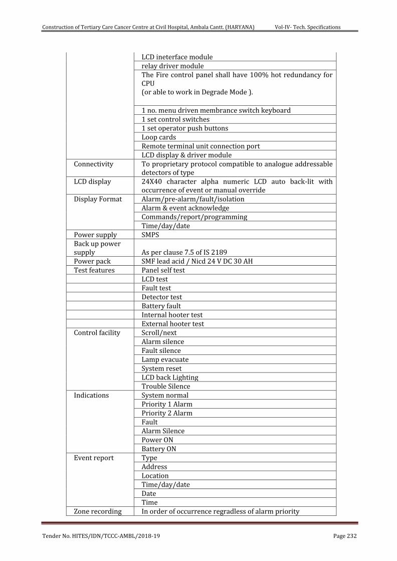
Construction of Tertiary Care Cancer Centre at Civil Hospital, Ambala Cantt. (HARYANA) Vol-IV- Tech. Specifications
Tender No. HITES/IDN/TCCC-AMBL/2018-19 Page 232
LCD ineterface module relay driver module The Fire control panel shall have 100% hot redundancy for CPU (or able to work in Degrade Mode ). 1 no. menu driven membrance switch keyboard 1 set control switches 1 set operator push buttons Loop cards Remote terminal unit connection port LCD display & driver module
Connectivity To proprietary protocol compatible to analogue addressable detectors of type
LCD display 24X40 character alpha numeric LCD auto back-lit with occurrence of event or manual override
Display Format Alarm/pre-alarm/fault/isolation Alarm & event acknowledge Commands/report/programming Time/day/date
Power supply SMPS Back up power supply As per clause 7.5 of IS 2189 Power pack SMF lead acid / Nicd 24 V DC 30 AH Test features Panel self test LCD test Fault test Detector test Battery fault Internal hooter test External hooter test Control facility Scroll/next
Alarm silence Fault silence Lamp evacuate System reset LCD back Lighting Trouble Silence
Indications System normal Priority 1 Alarm Priority 2 Alarm Fault Alarm Silence Power ON Battery ON
Event report Type Address Location Time/day/date Date Time
Zone recording In order of occurrence regradless of alarm priority
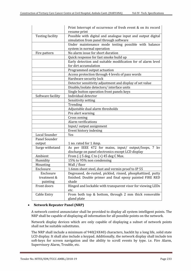
Construction of Tertiary Care Cancer Centre at Civil Hospital, Ambala Cantt. (HARYANA) Vol-IV- Tech. Specifications
Tender No. HITES/IDN/TCCC-AMBL/2018-19 Page 233
Print Interrupt of occurrence of fresh event & on its record resume print
Testing facility Possible with digital and analogue input and output digital simulation from panel through software
Under maintenance mode testing possible with balance system in normal operation
Fire pattern No alarm issue for short duration Quick response for fast smoke build up Early detection and suitable modification for of alarm level
for dirt accumulation Programmed output actuation Access protection through 4 levels of pass words Hardware security lock Detector sensitivity adjustment and display of set value Disable/isolate detectors/ interface units Single button operation front panels keys Software facility Individual detector Sensitivity setting Trending Adjustable dual alarm thresholds Pre alert warning Cross zoning Alarm verifications Input/ output assignment Event history indexing Local Sounder Yes Panel Sounder output 1 no. rated for 1 Amp. Surge withstand As per IEEE 472 for mains, input/ output/loops, 7 kv
discharge on panel electronics except LCD display Ambient From (-) 5 deg. C to (+) 45 deg C Max. Humidity 15% to 95% non condensing Mounting Wall / floor Enclosure 1.6mm sheet steel, dust and vermin proof to IP 55
Enclosure treatment &
painting
Degreased, de-rusted, pickled, rinsed, phosphattized, putty finished. Double primer and final epoxy painted FIRE RED shade
Front doors Hinged and lockable with transparent visor for viewing LEDs etc.
Cable Entry From both top & bottom, through 2 mm thick removable gland plate
Network Repeater Panel (NRP)
A network control annunciator shall be provided to display all system intelligent points. The NRP shall be capable of displaying all information for all possible points on the network.
Network display devices which are only capable of displaying a subset of network points shall not be suitable substitutes.
The NRP shall include a minimum of 940(24X40) characters, backlit by a long life, solid state LCD display. It shall also include a keypad. Additionally, the network display shall include ten soft-keys for screen navigation and the ability to scroll events by type. i.e. Fire Alarm, Supervisory Alarm, Trouble, etc.
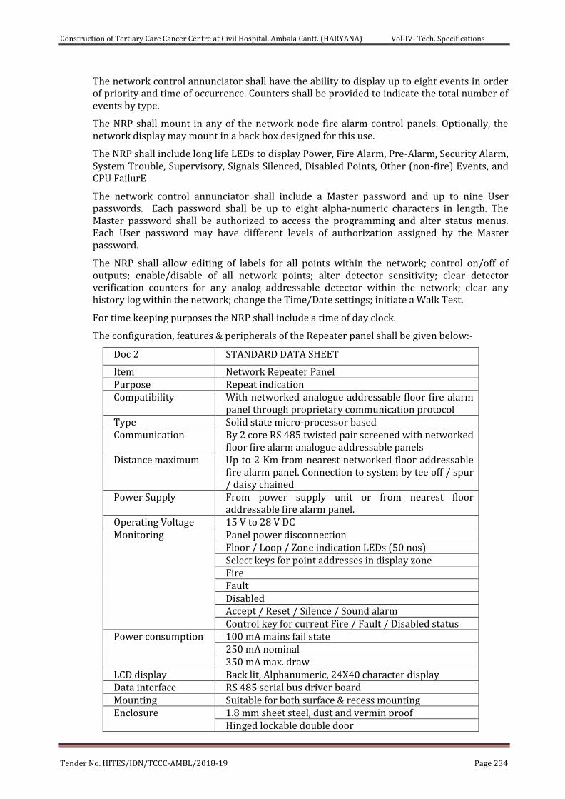
Construction of Tertiary Care Cancer Centre at Civil Hospital, Ambala Cantt. (HARYANA) Vol-IV- Tech. Specifications
Tender No. HITES/IDN/TCCC-AMBL/2018-19 Page 234
The network control annunciator shall have the ability to display up to eight events in order of priority and time of occurrence. Counters shall be provided to indicate the total number of events by type.
The NRP shall mount in any of the network node fire alarm control panels. Optionally, the network display may mount in a back box designed for this use.
The NRP shall include long life LEDs to display Power, Fire Alarm, Pre-Alarm, Security Alarm, System Trouble, Supervisory, Signals Silenced, Disabled Points, Other (non-fire) Events, and CPU FailurE
The network control annunciator shall include a Master password and up to nine User passwords. Each password shall be up to eight alpha-numeric characters in length. The Master password shall be authorized to access the programming and alter status menus. Each User password may have different levels of authorization assigned by the Master password.
The NRP shall allow editing of labels for all points within the network; control on/off of outputs; enable/disable of all network points; alter detector sensitivity; clear detector verification counters for any analog addressable detector within the network; clear any history log within the network; change the Time/Date settings; initiate a Walk Test.
For time keeping purposes the NRP shall include a time of day clock.
The configuration, features & peripherals of the Repeater panel shall be given below:-
Doc 2 STANDARD DATA SHEET
Item Network Repeater Panel Purpose Repeat indication Compatibility With networked analogue addressable floor fire alarm
panel through proprietary communication protocol Type Solid state micro-processor based Communication By 2 core RS 485 twisted pair screened with networked
floor fire alarm analogue addressable panels Distance maximum Up to 2 Km from nearest networked floor addressable
fire alarm panel. Connection to system by tee off / spur / daisy chained
Power Supply From power supply unit or from nearest floor addressable fire alarm panel.
Operating Voltage 15 V to 28 V DC Monitoring Panel power disconnection
Floor / Loop / Zone indication LEDs (50 nos) Select keys for point addresses in display zone Fire Fault Disabled Accept / Reset / Silence / Sound alarm Control key for current Fire / Fault / Disabled status
Power consumption 100 mA mains fail state 250 mA nominal 350 mA max. draw
LCD display Back lit, Alphanumeric, 24X40 character display Data interface RS 485 serial bus driver board Mounting Suitable for both surface & recess mounting Enclosure 1.8 mm sheet steel, dust and vermin proof
Hinged lockable double door
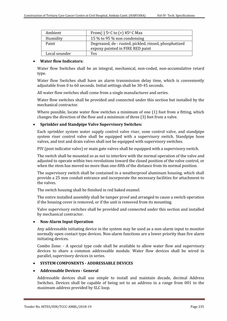
Construction of Tertiary Care Cancer Centre at Civil Hospital, Ambala Cantt. (HARYANA) Vol-IV- Tech. Specifications
Tender No. HITES/IDN/TCCC-AMBL/2018-19 Page 235
Ambient From(-) 5o C to (+) 450 C Max Humidity 15 % to 95 % non condensing Paint Degreased, de - rusted, pickled, rinsed, phosphatized
expoxy painted in FIRE RED paint Local sounder Yes
Water flow Indicators:
Water flow Switches shall be an integral, mechanical, non-coded, non-accumulative retard type.
Water flow Switches shall have an alarm transmission delay time, which is conveniently adjustable from 0 to 60 seconds. Initial settings shall be 30-45 seconds.
All water flow switches shall come from a single manufacturer and series.
Water flow switches shall be provided and connected under this section but installed by the mechanical contractor.
Where possible, locate water flow switches a minimum of one (1) foot from a fitting, which changes the direction of the flow and a minimum of three (3) feet from a valve.
Sprinkler and Standpipe Valve Supervisory Switches:
Each sprinkler system water supply control valve riser, zone control valve, and standpipe system riser control valve shall be equipped with a supervisory switch. Standpipe hose valves, and test and drain valves shall not be equipped with supervisory switches.
PIV (post indicator valve) or main gate valves shall be equipped with a supervisory switch.
The switch shall be mounted so as not to interfere with the normal operation of the valve and adjusted to operate within two revolutions toward the closed position of the valve control, or when the stem has moved no more than one-fifth of the distance from its normal position.
The supervisory switch shall be contained in a weatherproof aluminum housing, which shall provide a 25 mm conduit entrance and incorporate the necessary facilities for attachment to the valves.
The switch housing shall be finished in red baked enamel.
The entire installed assembly shall be tamper proof and arranged to cause a switch operation if the housing cover is removed, or if the unit is removed from its mounting.
Valve supervisory switches shall be provided and connected under this section and installed by mechanical contractor.
Non-Alarm Input Operation
Any addressable initiating device in the system may be used as a non-alarm input to monitor normally open contact type devices. Non-alarm functions are a lower priority than fire alarm initiating devices.
Combo Zone: - A special type code shall be available to allow water flow and supervisory devices to share a common addressable module. Water flow devices shall be wired in parallel, supervisory devices in series.
SYSTEM COMPONENTS - ADDRESSABLE DEVICES
Addressable Devices - General
Addressable devices shall use simple to install and maintain decade, decimal Address Switches. Devices shall be capable of being set to an address in a range from 001 to the maximum address provided by SLC loop.
Construction of Tertiary Care Cancer Centre at Civil Hospital, Ambala Cantt. (HARYANA) Vol-IV- Tech. Specifications
Tender No. HITES/IDN/TCCC-AMBL/2018-19 Page 236
Addressable devices, which use a binary address setting method, such as a Dip switch, are not an allowable substitute.
Detectors shall be intelligent (analog) and addressable, and shall connect with two wires to the FACP Signaling line circuit.
Addressable smoke and thermal detectors shall provide dual alarm and power/polling LEDs. Both LEDs shall flash under normal conditions, indicating that the detector is operational and in regular communication with the control panel, and both LEDs shall be placed into steady illumination by the control panel, indicating that an alarm condition has been detected. If required, the LED flash shall have the ability to be removed from the system program. An output connection shall also be provided in the base to connect an external remote alarm LED.
The fire alarm control panel shall permit detector sensitivity adjustment through field programming. Sensitivity shall be automatically adjusted by the panel on a time-of-day basis.
Using software in the FACP, detectors shall automatically compensate for dust accumulation and other slow environmental changes that may affect their performance. The detectors shall be listed by UL as meeting the calibrated sensitivity test requirements of NFPA Standard 72, Chapter 7 or EN 54.
The detectors shall be ceiling-mount and shall include a separate twist-lock base with tamper proof feature. Base shall include a sounder base with a built-in (local) sounder rated at 85 DB minimum, a relay base and an isolator base designed for Class A applications.
The detectors shall provide a test means whereby they will simulate an alarm condition and report that condition to the control panel. Such a test may be initiated at the detector itself (by activating a magnetic switch) or initiated remotely on command from the control panel.
Detectors shall also store an internal identifying type code that the control panel shall use to identify the type of device (Photoelectric, Thermal& Photo-thermal).
Detectors will operate in an analog fashion, where the detector simply measures its designed environment variable and transmits an analog value to the FACP based on real-time measured values. The FACP software, not the detector, shall make the alarm/normal decision, thereby allowing the sensitivity of each detector to be set in the FACP program and allowing the system operator to view the current analog value of each detector.
A magnetic test switch shall be provided to test detectors and modules. Detectors shall report an indication of an analog value reaching 100% of the alarm threshold.
Programmable Electronic Exit Point Directional Sounders
Electronic sounders shall operate on 24 VDC nominal. Electronic sounders shall be field programmable without the use of special tools, at a sound level of at least 90 dBA measured at 10 feet from the device. It shall be capable to broadcast preprogrammed Voice Message also and shall be flush or surface mounted as shown on plans. It shall produce broad-band directional sound to guide occupants to safe exists even in complete darkness.
Strobe lights shall meet the requirements of the ADA, UL Standard 1971, be fully synchronized, and shall meet the following criteria: The maximum pulse duration shall be 2/10 of one second.
Strobe intensity shall meet the requirements of UL 1971.
The flash rate shall meet the requirements of UL 1971.
Addressable Pull Box (manual station)
Addressable pull boxes shall, on command from the control panel, send data to the panel representing the state of the manual switch and the addressable communication module
Construction of Tertiary Care Cancer Centre at Civil Hospital, Ambala Cantt. (HARYANA) Vol-IV- Tech. Specifications
Tender No. HITES/IDN/TCCC-AMBL/2018-19 Page 237
status. They shall use a key operated test-reset lock, and shall be designed so that after actual emergency operation, they cannot be restored to normal use except by the use of a key.
All operated stations shall have a positive, visual indication of operation and utilize a key type reset.
Manual stations shall be constructed of Lexan with clearly visible operating instructions provided on the cover. The word FIRE shall appear on the front of the stations in raised letters, 1.75 inches or larger.
Intelligent Multi-Co-Operative Sensing Photoelectric Smoke Detector (As required)
The detectors shall use the photoelectric (light-scattering) principal to measure smoke density and shall be in position to work in advance multi Co-Operative Sensing, on command from the control panel, send data to the panel representing the analog level of smoke density.
Photo- electric Fire Alarm detector having photo electric smoke sensor and thermal sensor incorporated and shall send individual smoke sensitivity and temperature operation to panel having following technical specifications: -
o Operating Temperature - 0 to 50oC
o Humidity - 10 to 95%
o Smoke sensor sensitivity - 0.2% to 3.7% per foot of smoke Obstruction
o Smoke sensor Air velocity - 0-610 m/min
Intelligent Thermal Detectors (As required)
Thermal detectors shall be intelligent addressable devices rated at 135 degrees Fahrenheit (58 degrees Celsius) and have a fixed rate-of-rise element rated at 15 degrees F (9.4 degrees C) per minute. It shall connect via two wires to the fire alarm control panel signaling line circuit.
Intelligent Multi Criteria (Photo- Thermal) Acclimating Detector
The intelligent multi criteria Acclimate detector shall be an addressable device that is designed to monitor a minimum of photoelectric and thermal technologies in a single sensing device. The design shall include the ability to adapt to its environment by utilizing a built-in microprocessor to determine its environment and choose the appropriate sensing settings. The detector design shall allow a wide sensitivity window, no less than 1 to 4% per foot obscuration. This detector shall utilize advanced electronics that react to slow smoldering fires and thermal properties all within a single sensing device.
The microprocessor design shall be capable of selecting the appropriate sensitivity levels based on the environment type it is in (office, manufacturing, kitchen etc.) and then have the ability to automatically change the setting as the environment changes (as walls are moved or as the occupancy changes).
The intelligent multi criteria detection device shall include the ability to combine the signal of the thermal sensor with the signal of the photoelectric signal in an effort to react hastily in the event of a fire situation. It shall also include the inherent ability to distinguish between a fire condition and a false alarm condition by examining the characteristics of the thermal and smoke sensing chambers and comparing them to a database of actual fire and deceptive phenomena.
The detector shall have Isolator modules to automatically isolate wire-to-wire short circuits on an SLC Class A or Class B branch. The isolator module shall limit the number of detectors that may be rendered inoperative by a short circuit fault on the SLC loop segment or branch. At least one isolator module shall be provided for each floor or protected zone of the campus.
Construction of Tertiary Care Cancer Centre at Civil Hospital, Ambala Cantt. (HARYANA) Vol-IV- Tech. Specifications
Tender No. HITES/IDN/TCCC-AMBL/2018-19 Page 238
If a wire-to-wire short occurs, the isolator module shall automatically open-circuit (disconnect) the SLC. When the short circuit condition is corrected, the isolator module shall automatically reconnect the isolated section.
Two-Wire Detector Monitor Module
Addressable monitor modules shall be provided to connect one supervised IDC zone of conventional 2-wire smoke detectors or alarm initiating devices (any N.O. dry contact device).
The IDC zone may be wired for Class A or B (Style D or Style B) operation. An LED shall be provided that shall flash under normal conditions, indicating that the monitor module is operational and in regular communication with the control panel.
For difficult to reach areas, the monitor module shall be available in a miniature package and shall be no larger than 2-3/4 inch x 1-1/4 inch x 1/2 inch. This version need not include Style D or an LED.
Addressable Control Module
Addressable control modules shall be provided to supervise and control the operation of Lifts, sprinkler, switch gears etc., one conventional NACs of compatible, 24 VDC powered, polarized audio/visual notification appliances. For fan shutdown and other auxiliary control functions, the control module may be set to operate as a dry contact relay.
The control module NAC may be wired for Style Z or Style Y (Class A/B) with up to 1 amp of inductive A/V signal, or 2 amps of resistive A/V signal operation, or as a dry contact (Form-C) relay. The relay coil shall be magnetically latched to reduce wiring connection requirements, and to insure that 100% of all auxiliary relay or NACs may be energized at the same time on the same pair of wires.
Audio/visual power shall be provided by a separate supervised power loop from the main fire alarm control panel or from a supervised, UL listed remote power supply.
The control module shall be suitable for pilot duty applications and rated for a minimum of 0.6 amps at 30V DC.
Addressable Relay Module
Addressable Relay Modules shall be available for HVAC (AHUs &Ventilation Fans) control and other building functions. The relay shall be form C and rated for a minimum of 2.0 Amps resistive or 1.0 Amps inductive. The relay coil shall be magnetically latched to reduce wiring connection requirements, and to insure that 100% of all auxiliary relay or NACs may be energized at the same time on the same pair of wires.
EXECUTION
INSTALLATION:
a. Installation shall be in accordance with the NEC, NFPA 72, local and state codes, as shown on the drawings, and as recommended by the major equipment manufacturer.
b. All conduit, junction boxes, conduit supports and hangers shall be concealed in finished areas and may be exposed in unfinished areas. Smoke detectors shall not be installed prior to the system programming and test period. If construction is ongoing during this period, measures shall be taken to protect smoke detectors from contamination and physical damage.
c. All fire detection and alarm system devices, control panels and remote annunciators shall be flush mounted when located in finished areas and may be surface mounted when located in unfinished areas.
Construction of Tertiary Care Cancer Centre at Civil Hospital, Ambala Cantt. (HARYANA) Vol-IV- Tech. Specifications
Tender No. HITES/IDN/TCCC-AMBL/2018-19 Page 239
d. Manual Pull Stations shall be suitable for surface mounting or semi flush mounting as shown on the plans, and shall be installed not less than 42 inches, nor more than 48 inches above the finished floor.
e. Manual Pull Station of Metal Die cast body & meeting requirments of UL 38, Para No 3.2.1 & NFPA-72, Para No-17.4.2.
TYPICAL OPERATION:
Actuation of any manual station, smoke detector, heat detector or water flow switch shall cause the following operations to occur unless otherwise specified:
Activate all programmed speaker circuits.
Actuate hooter units until the panel is reset.
Light the associated indicators corresponding to active speaker circuits.
Release all magnetic door holders to doors to adjacent zones on the floor from which the alarm was initiated.
Where required, return all elevators to the primary or alternate floor of egress.
A smoke detector in any elevator lobby shall, in addition to the above functions, return all elevators to the primary or alternate floor of egress.
Smoke detectors in the elevator machine room or top of hoistway shall return all elevators in to the primary or alternate floor. Smoke detectors or heat detectors installed to shut down elevator power shall do so in accordance with ANSI A17.1 requirements and be coordinated with the electrical contractor.
Duct type smoke detectors shall, in addition to the above functions, shut down the ventilation system or close associated control dampers as appropriate.
Activation of any sprinkler system low-pressure switch, on valve tamper switch, shall cause a system supervisory alarm indication.
HVAC/Smoke Control System Operation:
On/Auto/Off switches and status indicators (LEDS) shall be provided for monitoring and manual control of each fan, damper, HVAC control unit, stairwell pressurization fan, and smoke exhaust fan.
The OFF LED shall be Yellow, the ON LED shall be green, and the Trouble/Fault LED shall be Amber/Orange for each switch. The Trouble/Fault indicator shall indicate a trouble in the control and/or monitor points associated with that switch. In addition, each group of eight switches shall have two LEDS and one momentary switch which allow the following functions: An Amber LED to indicate an OFF-NORMAL switch position, in the ON or OFF position; A Green LED to indicate ALL AUTO switch position; A Local Acknowledge/Lamp Test momentary switch.
Each switch shall have the capability to monitor and control two addressable inputs and two addressable outputs. In all modes, the ON and OFF indicators shall continuously follow the device status not the switch position. Positive feedback shall be employed to verify correct operation of the device being controlled. Systems that indicate on/off/auto by physical switch position only are not acceptable.
All HVAC switches (i.e., limit switches, vane switches, etc.) which shall be provided and installed by the HVAC contractor, but the detail of the switches required shall be provided by the vendor for fire alarm system as per the equipment layout in the building.
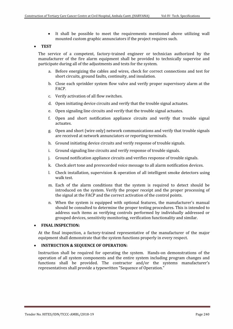
Construction of Tertiary Care Cancer Centre at Civil Hospital, Ambala Cantt. (HARYANA) Vol-IV- Tech. Specifications
Tender No. HITES/IDN/TCCC-AMBL/2018-19 Page 240
It shall be possible to meet the requirements mentioned above utilizing wall mounted custom graphic annunciators if the project requires such.
TEST
The service of a competent, factory-trained engineer or technician authorized by the manufacturer of the fire alarm equipment shall be provided to technically supervise and participate during all of the adjustments and tests for the system.
a. Before energizing the cables and wires, check for correct connections and test for short circuits, ground faults, continuity, and insulation.
b. Close each sprinkler system flow valve and verify proper supervisory alarm at the FACP.
c. Verify activation of all flow switches.
d. Open initiating device circuits and verify that the trouble signal actuates.
e. Open signaling line circuits and verify that the trouble signal actuates.
f. Open and short notification appliance circuits and verify that trouble signal actuates.
g. Open and short (wire only) network communications and verify that trouble signals are received at network annunciators or reporting terminals.
h. Ground initiating device circuits and verify response of trouble signals.
i. Ground signaling line circuits and verify response of trouble signals.
j. Ground notification appliance circuits and verifies response of trouble signals.
k. Check alert tone and prerecorded voice message to all alarm notification devices.
l. Check installation, supervision & operation of all intelligent smoke detectors using walk test.
m. Each of the alarm conditions that the system is required to detect should be introduced on the system. Verify the proper receipt and the proper processing of the signal at the FACP and the correct activation of the control points.
n. When the system is equipped with optional features, the manufacturer's manual should be consulted to determine the proper testing procedures. This is intended to address such items as verifying controls performed by individually addressed or grouped devices, sensitivity monitoring, verification functionality and similar.
FINAL INSPECTION:
At the final inspection, a factory-trained representative of the manufacturer of the major equipment shall demonstrate that the system functions properly in every respect.
INSTRUCTION & SEQUENCE OF OPERATION:
Instruction shall be required for operating the system. Hands-on demonstrations of the operation of all system components and the entire system including program changes and functions shall be provided. The contractor and/or the systems manufacturer's representatives shall provide a typewritten "Sequence of Operation."
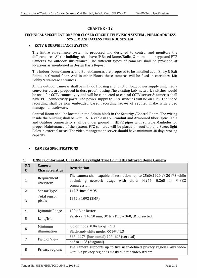
Construction of Tertiary Care Cancer Centre at Civil Hospital, Ambala Cantt. (HARYANA) Vol-IV- Tech. Specifications
Tender No. HITES/IDN/TCCC-AMBL/2018-19 Page 241
CHAPTER - 12
TECHNICAL SPECIFICATIONS FOR CLOSED CIRCUIT TELEVISION SYSTEM , PUBLIC ADDRESS SYSTEM AND ACCESS CONTROL SYSTEM
CCTV & SURVEILLANCE SYSTEM
The Entire surveillance system is proposed and designed to control and monitors the different area. All the buildings shall have IP Based Dome/Bullet Camera indoor type and PTZ Cameras for outdoor surveillance. The different types of cameras shall be provided at locations as mentioned in Design Basis Report.
The indoor Dome Cameras and Bullet Cameras are proposed to be installed at all Entry & Exit Points in Ground floor. And in other Floors these cameras will be fixed in corridors, Lift Lobby & staircase entrances.
All the outdoor cameras shall be in IP 66 Housing and Junction box, power supply unit, media converter etc are proposed in dust proof housing The existing LAN network switches would be used for CCTV connectivity and will be connected to central CCTV server & cameras shall have POE connectivity ports. The power supply to LAN switches will be on UPS. The video recording shall be non embedded based recording server of reputed make with video management software.
Control Room shall be located in the Admin block in the Security /Control Room. The wiring inside the building shall be with CAT 6 cable in PVC conduit and Armoured fiber Optic Cable and Outdoor connectivity shall be under ground in HDPE pipes with suitable Manholes for proper Maintenance of the system. PTZ cameras will be placed on roof top and Street light Poles in external areas. The video management server should have minimum 30 days storing capacity.
CAMERA SPECIFICATIONS
1. ONVIF Conformant, UL Listed Day/Night True IP Full HD Infrared Dome Camera
S.N
O. Camera
Characteristics Description
1 Requirement
Overview
The camera shall capable of resolutions up to 2560x1920 @ 30 fPS while
optimizing network usage with either H.264, H.265 or MJPEG
compression.
2 Sensor Type 1/2.7‑inch CMOS
3 Total sensor pixels
1952 x 1092 (2MP)
4 Dynamic Range 100 dB or Better
5 Lens/Iris Varifocal 3 to 10 mm, DC Iris F1.5 – 360, IR corrected
6 Minimum
illumination
Color mode: 0.04 lux @ F 1.3
Black-and-white mode: .001@ f 1.3
7 Field of View 36° - 117° (horizontal) 20° - 61° (vertical)
64° to 113° (diagonal)
8 Privacy regions The camera supports up to five user-defined privacy regions. Any video
within a privacy region is masked in the video stream.
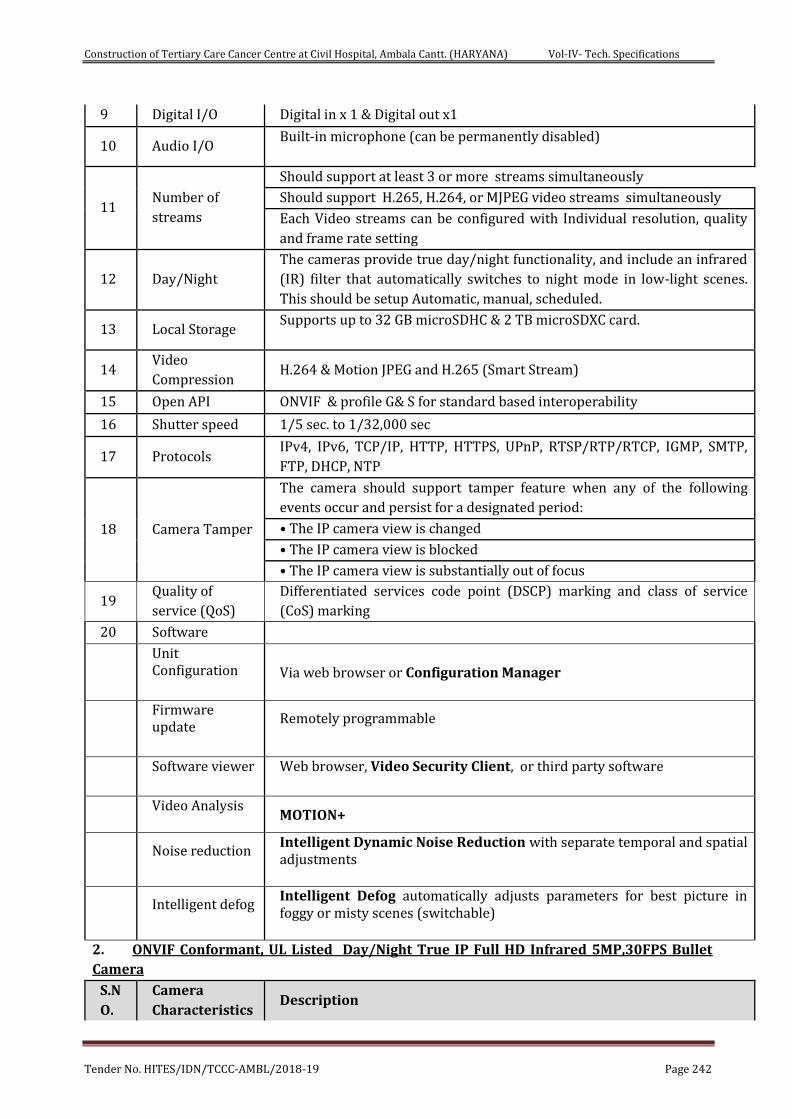
Construction of Tertiary Care Cancer Centre at Civil Hospital, Ambala Cantt. (HARYANA) Vol-IV- Tech. Specifications
Tender No. HITES/IDN/TCCC-AMBL/2018-19 Page 242
9 Digital I/O Digital in x 1 & Digital out x1
10 Audio I/O Built-in microphone (can be permanently disabled)
11 Number of
streams
Should support at least 3 or more streams simultaneously
Should support H.265, H.264, or MJPEG video streams simultaneously
Each Video streams can be configured with Individual resolution, quality
and frame rate setting
12 Day/Night The cameras provide true day/night functionality, and include an infrared
(IR) filter that automatically switches to night mode in low-light scenes.
This should be setup Automatic, manual, scheduled.
13 Local Storage Supports up to 32 GB microSDHC & 2 TB microSDXC card.
14 Video
Compression H.264 & Motion JPEG and H.265 (Smart Stream)
15 Open API ONVIF & profile G& S for standard based interoperability
16 Shutter speed 1/5 sec. to 1/32,000 sec
17 Protocols IPv4, IPv6, TCP/IP, HTTP, HTTPS, UPnP, RTSP/RTP/RTCP, IGMP, SMTP,
FTP, DHCP, NTP
18 Camera Tamper
The camera should support tamper feature when any of the following
events occur and persist for a designated period:
• The IP camera view is changed
• The IP camera view is blocked
• The IP camera view is substantially out of focus
19 Quality of
service (QoS) Differentiated services code point (DSCP) marking and class of service
(CoS) marking
20 Software
Unit Configuration
Via web browser or Configuration Manager
Firmware update
Remotely programmable
Software viewer
Web browser, Video Security Client, or third party software
Video Analysis
MOTION+
Noise reduction
Intelligent Dynamic Noise Reduction with separate temporal and spatial adjustments
Intelligent defog
Intelligent Defog automatically adjusts parameters for best picture in foggy or misty scenes (switchable)
2. ONVIF Conformant, UL Listed Day/Night True IP Full HD Infrared 5MP,30FPS Bullet
Camera
S.N
O. Camera
Characteristics Description
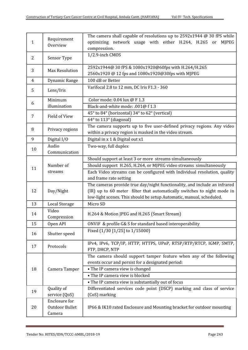
Construction of Tertiary Care Cancer Centre at Civil Hospital, Ambala Cantt. (HARYANA) Vol-IV- Tech. Specifications
Tender No. HITES/IDN/TCCC-AMBL/2018-19 Page 243
1 Requirement
Overview
The camera shall capable of resolutions up to 2592x1944 @ 30 fPS while
optimizing network usage with either H.264, H.265 or MJPEG
compression.
2 Sensor Type 1/2.9-inch CMOS
3 Max Resolution 2592x1944@ 30 fPS & 1080x1920@60fps with H.264/H.265 2560x1920 @ 12 fps and 1080x1920@30fps with MJPEG
4 Dynamic Range 100 dB or Better
5 Lens/Iris Varifocal 2.8 to 12 mm, DC Iris F1.3 - 360
6 Minimum
illumination
Color mode: 0.04 lux @ F 1.3
Black-and-white mode: .001@ f 1.3
7 Field of View 45° to 84° (horizontal) 34° to 62° (vertical)
64° to 113° (diagonal)
8 Privacy regions The camera supports up to five user-defined privacy regions. Any video
within a privacy region is masked in the video stream.
9 Digital I/O Digital in x 1 & Digital out x1
10 Audio
Communication Two-way, full duplex
11 Number of
streams
Should support at least 3 or more streams simultaneously
Should support H.265, H.264, or MJPEG video streams simultaneously
Each Video streams can be configured with Individual resolution, quality
and frame rate setting
12 Day/Night The cameras provide true day/night functionality, and include an infrared
(IR) up to 60 meter filter that automatically switches to night mode in
low-light scenes. This should be setup Automatic, manual, scheduled.
13 Local Storage Micro SD
14 Video
Compression H.264 & Motion JPEG and H.265 (Smart Stream)
15 Open API ONVIF & profile G& S for standard based interoperability
16 Shutter speed Fixed (1/30 [1/25] to 1/15000)
17 Protocols IPv4, IPv6, TCP/IP, HTTP, HTTPS, UPnP, RTSP/RTP/RTCP, IGMP, SMTP,
FTP, DHCP, NTP
18 Camera Tamper
The camera should support tamper feature when any of the following
events occur and persist for a designated period:
• The IP camera view is changed
• The IP camera view is blocked
• The IP camera view is substantially out of focus
19 Quality of
service (QoS) Differentiated services code point (DSCP) marking and class of service
(CoS) marking
20 Enclosure for
Outdoor Bullet
Camera IP66 & IK10 rated Enclosure and Mounting bracket for outdoor mounting
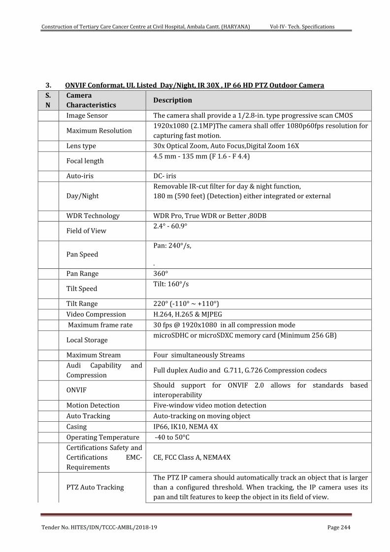
Construction of Tertiary Care Cancer Centre at Civil Hospital, Ambala Cantt. (HARYANA) Vol-IV- Tech. Specifications
Tender No. HITES/IDN/TCCC-AMBL/2018-19 Page 244
3. ONVIF Conformat, UL Listed Day/Night, IR 30X , IP 66 HD PTZ Outdoor Camera
S.
N Camera
Characteristics Description
Image Sensor The camera shall provide a 1/2.8-in. type progressive scan CMOS
Maximum Resolution 1920x1080 (2.1MP)The camera shall offer 1080p60fps resolution for
capturing fast motion.
Lens type 30x Optical Zoom, Auto Focus,Digital Zoom 16X
Focal length 4.5 mm - 135 mm (F 1.6 - F 4.4)
Auto-iris DC- iris
Day/Night Removable IR-cut filter for day & night function, 180 m (590 feet) (Detection) either integrated or external
WDR Technology WDR Pro, True WDR or Better ,80DB
Field of View 2.4° - 60.9°
Pan Speed Pan: 240°/s, .
Pan Range 360°
Tilt Speed Tilt: 160°/s
Tilt Range 220° (-110° ~ +110°)
Video Compression H.264, H.265 & MJPEG
Maximum frame rate 30 fps @ 1920x1080 in all compression mode
Local Storage microSDHC or microSDXC memory card (Minimum 256 GB)
Maximum Stream Four simultaneously Streams
Audi Capability and
Compression Full duplex Audio and G.711, G.726 Compression codecs
ONVIF Should support for ONVIF 2.0 allows for standards based
interoperability
Motion Detection Five-window video motion detection
Auto Tracking Auto-tracking on moving object
Casing IP66, IK10, NEMA 4X
Operating Temperature -40 to 50°C
Certifications Safety and
Certifications EMC-
Requirements CE, FCC Class A, NEMA4X
PTZ Auto Tracking The PTZ IP camera should automatically track an object that is larger
than a configured threshold. When tracking, the IP camera uses its
pan and tilt features to keep the object in its field of view.
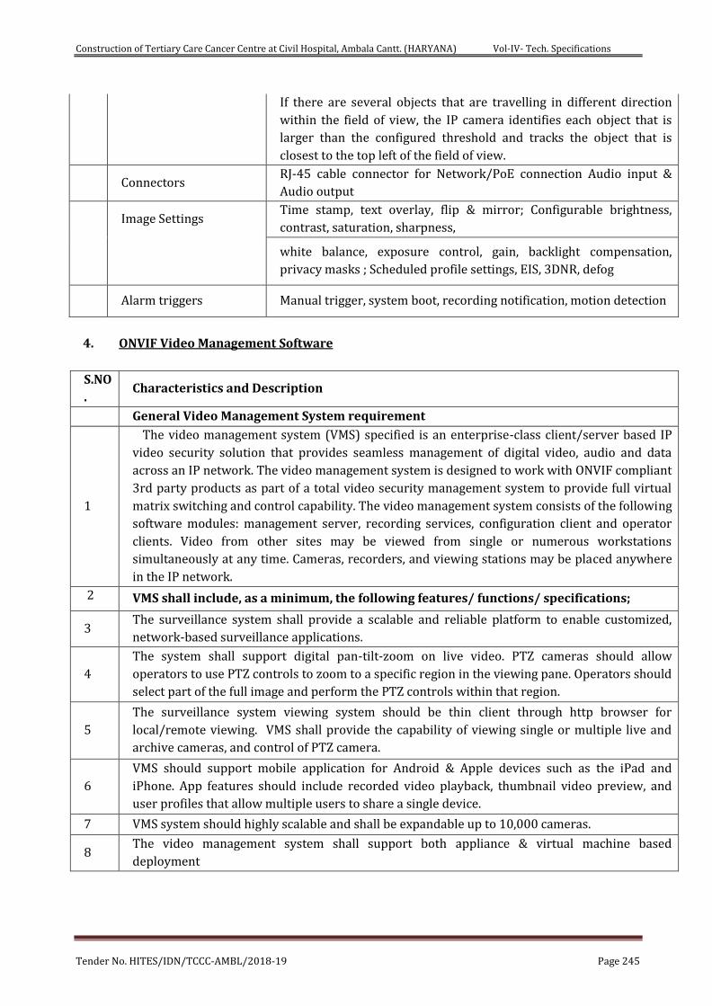
Construction of Tertiary Care Cancer Centre at Civil Hospital, Ambala Cantt. (HARYANA) Vol-IV- Tech. Specifications
Tender No. HITES/IDN/TCCC-AMBL/2018-19 Page 245
If there are several objects that are travelling in different direction
within the field of view, the IP camera identifies each object that is
larger than the configured threshold and tracks the object that is
closest to the top left of the field of view.
Connectors RJ-45 cable connector for Network/PoE connection Audio input &
Audio output
Image Settings Time stamp, text overlay, flip & mirror; Configurable brightness,
contrast, saturation, sharpness,
white balance, exposure control, gain, backlight compensation,
privacy masks ; Scheduled profile settings, EIS, 3DNR, defog
Alarm triggers Manual trigger, system boot, recording notification, motion detection
4. ONVIF Video Management Software
S.NO
. Characteristics and Description
General Video Management System requirement
1
The video management system (VMS) specified is an enterprise-class client/server based IP
video security solution that provides seamless management of digital video, audio and data
across an IP network. The video management system is designed to work with ONVIF compliant
3rd party products as part of a total video security management system to provide full virtual
matrix switching and control capability. The video management system consists of the following
software modules: management server, recording services, configuration client and operator
clients. Video from other sites may be viewed from single or numerous workstations
simultaneously at any time. Cameras, recorders, and viewing stations may be placed anywhere
in the IP network.
2 VMS shall include, as a minimum, the following features/ functions/ specifications;
3 The surveillance system shall provide a scalable and reliable platform to enable customized,
network-based surveillance applications.
4 The system shall support digital pan-tilt-zoom on live video. PTZ cameras should allow
operators to use PTZ controls to zoom to a specific region in the viewing pane. Operators should
select part of the full image and perform the PTZ controls within that region.
5 The surveillance system viewing system should be thin client through http browser for
local/remote viewing. VMS shall provide the capability of viewing single or multiple live and
archive cameras, and control of PTZ camera.
6 VMS should support mobile application for Android & Apple devices such as the iPad and
iPhone. App features should include recorded video playback, thumbnail video preview, and
user profiles that allow multiple users to share a single device.
7 VMS system should highly scalable and shall be expandable up to 10,000 cameras.
8 The video management system shall support both appliance & virtual machine based
deployment
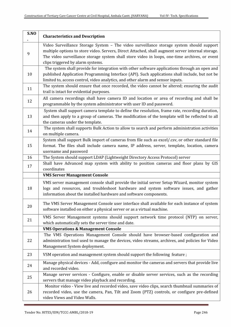
Construction of Tertiary Care Cancer Centre at Civil Hospital, Ambala Cantt. (HARYANA) Vol-IV- Tech. Specifications
Tender No. HITES/IDN/TCCC-AMBL/2018-19 Page 246
S.NO
. Characteristics and Description
9
Video Surveillance Storage System – The video surveillance storage system should support
multiple options to store video. Servers, Direct Attached, shall augment server internal storage.
The video surveillance storage system shall store video in loops, one-time archives, or event
clips triggered by alarm systems.
10 The system shall provide for integration with other software applications through an open and
published Application Programming Interface (API). Such applications shall include, but not be
limited to, access control, video analytics, and other alarm and sensor inputs.
11 The system should ensure that once recorded, the video cannot be altered; ensuring the audit
trail is intact for evidential purposes.
12 All camera recordings shall have camera ID and location or area of recording and shall be
programmable by the system administrator with user ID and password.
13 System shall support camera template to define the resolution, frame rate, recording duration,
and then apply to a group of cameras. The modification of the template will be reflected to all
the cameras under the template.
14 The system shall supports Bulk Action to allow to search and perform administration activities
on multiple camera.
15 System shall support Bulk import of cameras from file such as excel/.csv, or other standard file
format. The files shall include camera name, IP address, server, template, location, camera
username and password
16 The System should support LDAP (Lightweight Directory Access Protocol) server
17 Shall have Advanced map system with ability to position cameras and floor plans by GIS
coordinates
VMS Server Management Console
18 VMS server management console shall provide the initial server Setup Wizard, monitor system
logs and resources, and troubleshoot hardware and system software issues, and gather
information about the installed hardware and software components.
20 The VMS Server Management Console user interface shall available for each instance of system
software installed on either a physical server or as a virtual machine.
21 VMS Server Management systems should support network time protocol (NTP) on server,
which automatically sets the server time and date.
VMS Operations & Management Console
22 The VMS Operations Management Console should have browser-based configuration and
administration tool used to manage the devices, video streams, archives, and policies for Video
Management System deployment.
23 VSM operation and management system should support the following feature ;
24 Manage physical devices - Add, configure and monitor the cameras and servers that provide live
and recorded video.
25 Manage server services - Configure, enable or disable server services, such as the recording
servers that manage video playback and recording.
26 Monitor video - View live and recorded video, save video clips, search thumbnail summaries of
recorded video, use the camera, Pan, Tilt and Zoom (PTZ) controls, or configure pre-defined
video Views and Video Walls.
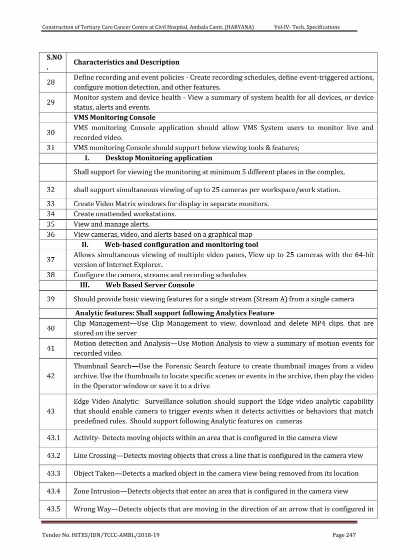
Construction of Tertiary Care Cancer Centre at Civil Hospital, Ambala Cantt. (HARYANA) Vol-IV- Tech. Specifications
Tender No. HITES/IDN/TCCC-AMBL/2018-19 Page 247
S.NO
. Characteristics and Description
28 Define recording and event policies - Create recording schedules, define event-triggered actions,
configure motion detection, and other features.
29 Monitor system and device health - View a summary of system health for all devices, or device
status, alerts and events.
VMS Monitoring Console
30 VMS monitoring Console application should allow VMS System users to monitor live and
recorded video.
31 VMS monitoring Console should support below viewing tools & features;
I. Desktop Monitoring application
Shall support for viewing the monitoring at minimum 5 different places in the complex.
32 shall support simultaneous viewing of up to 25 cameras per workspace/work station.
33 Create Video Matrix windows for display in separate monitors.
34 Create unattended workstations.
35 View and manage alerts.
36 View cameras, video, and alerts based on a graphical map
II. Web-based configuration and monitoring tool
37 Allows simultaneous viewing of multiple video panes, View up to 25 cameras with the 64-bit
version of Internet Explorer.
38 Configure the camera, streams and recording schedules
III. Web Based Server Console
39 Should provide basic viewing features for a single stream (Stream A) from a single camera
Analytic features: Shall support following Analytics Feature
40 Clip Management—Use Clip Management to view, download and delete MP4 clips. that are
stored on the server
41 Motion detection and Analysis—Use Motion Analysis to view a summary of motion events for
recorded video.
42 Thumbnail Search—Use the Forensic Search feature to create thumbnail images from a video
archive. Use the thumbnails to locate specific scenes or events in the archive, then play the video
in the Operator window or save it to a drive
43 Edge Video Analytic: Surveillance solution should support the Edge video analytic capability
that should enable camera to trigger events when it detects activities or behaviors that match
predefined rules. Should support following Analytic features on cameras
43.1 Activity- Detects moving objects within an area that is configured in the camera view
43.2 Line Crossing—Detects moving objects that cross a line that is configured in the camera view
43.3 Object Taken—Detects a marked object in the camera view being removed from its location
43.4 Zone Intrusion—Detects objects that enter an area that is configured in the camera view
43.5 Wrong Way—Detects objects that are moving in the direction of an arrow that is configured in
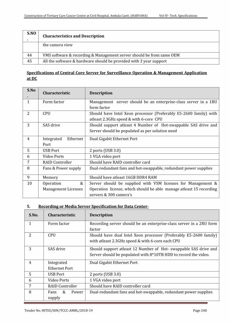
Construction of Tertiary Care Cancer Centre at Civil Hospital, Ambala Cantt. (HARYANA) Vol-IV- Tech. Specifications
Tender No. HITES/IDN/TCCC-AMBL/2018-19 Page 248
S.NO
. Characteristics and Description
the camera view
44 VMS software & recording & Management server should be from same OEM
45 All the software & hardware should be provided with 3 year support
Specifications of Central Core Server for Surveillance Operation & Management Application
at DC
S.No
. Characteristic Description
1 Form factor Management server should be an enterprise-class server in a 1RU
form factor
2 CPU Should have Intel Xeon processor (Preferably E5-2600 family) with
atleast 2.3GHz speed & with 6-core CPU
3 SAS drive Should support atleast 4 Number of Hot-swappable SAS drive and
Server should be populated as per solution need
4 Integrated Ethernet
Port Dual Gigabit Ethernet Port
5 USB Port 2 ports (USB 3.0)
6 Video Ports 1 VGA video port
7 RAID Controller Should have RAID controller card
8 Fans & Power supply Dual-redundant fans and hot-swappable, redundant power supplies
9 Memory Should have atleast 16GB DDR4 RAM
10 Operation &
Management Licenses Server should be supplied with VSM licenses for Management &
Operation license, which should be able manage atleast 15 recording
servers & 300 camera's
5. Recording or Media Server Specification for Data Center-
S.No. Characteristic Description
1 Form factor Recording server should be an enterprise-class server in a 2RU form
factor
2 CPU Should have dual Intel Xeon processor (Preferably E5-2600 family)
with atleast 2.3GHz speed & with 6-core each CPU
3 SAS drive Should support atleast 12 Number of Hot- swappable SAS drive and
Server should be populated with 8*10TB HDD to record the video.
4 Integrated
Ethernet Port Dual Gigabit Ethernet Port
5 USB Port 2 ports (USB 3.0)
6 Video Ports 1 VGA video port
7 RAID Controller Should have RAID controller card
8 Fans & Power
supply Dual-redundant fans and hot-swappable, redundant power supplies
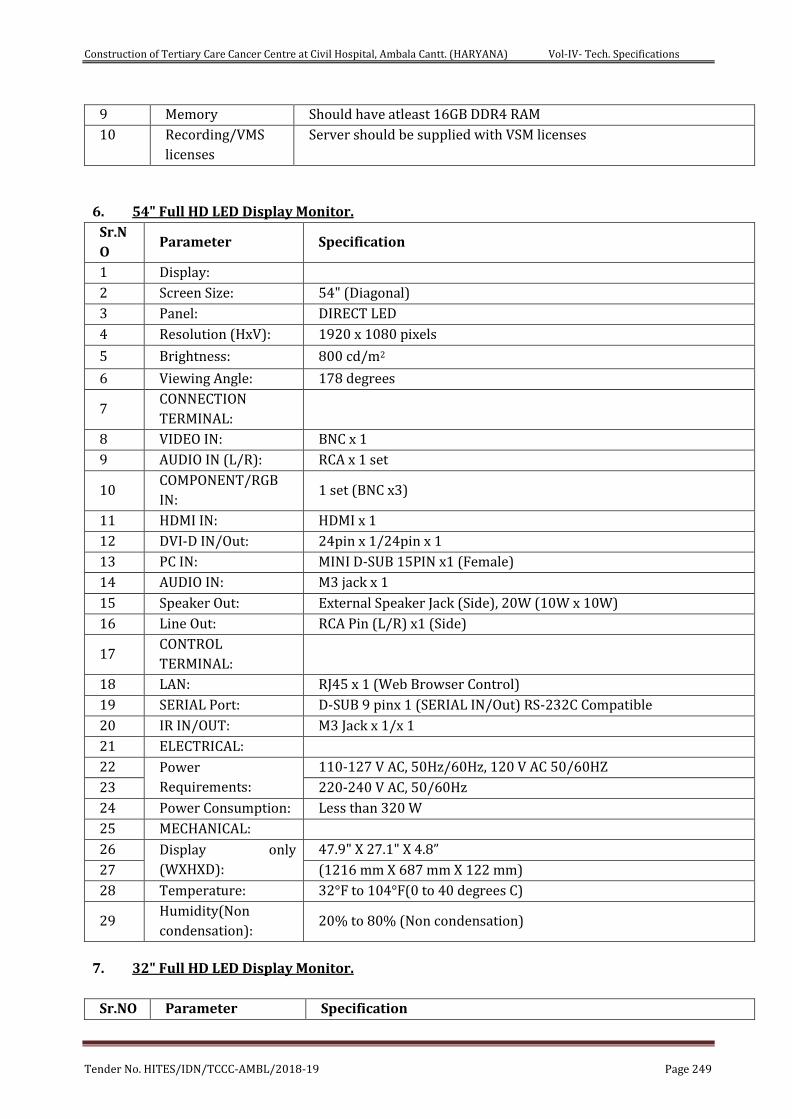
Construction of Tertiary Care Cancer Centre at Civil Hospital, Ambala Cantt. (HARYANA) Vol-IV- Tech. Specifications
Tender No. HITES/IDN/TCCC-AMBL/2018-19 Page 249
9 Memory Should have atleast 16GB DDR4 RAM
10 Recording/VMS
licenses Server should be supplied with VSM licenses
6. 54" Full HD LED Display Monitor.
Sr.N
O Parameter Specification
1 Display:
2 Screen Size: 54" (Diagonal)
3 Panel: DIRECT LED
4 Resolution (HxV): 1920 x 1080 pixels
5 Brightness: 800 cd/m2
6 Viewing Angle: 178 degrees
7 CONNECTION
TERMINAL:
8 VIDEO IN: BNC x 1
9 AUDIO IN (L/R): RCA x 1 set
10 COMPONENT/RGB
IN: 1 set (BNC x3)
11 HDMI IN: HDMI x 1
12 DVI-D IN/Out: 24pin x 1/24pin x 1
13 PC IN: MINI D-SUB 15PIN x1 (Female)
14 AUDIO IN: M3 jack x 1
15 Speaker Out: External Speaker Jack (Side), 20W (10W x 10W)
16 Line Out: RCA Pin (L/R) x1 (Side)
17 CONTROL
TERMINAL:
18 LAN: RJ45 x 1 (Web Browser Control)
19 SERIAL Port: D-SUB 9 pinx 1 (SERIAL IN/Out) RS-232C Compatible
20 IR IN/OUT: M3 Jack x 1/x 1
21 ELECTRICAL:
22 Power
Requirements:
110-127 V AC, 50Hz/60Hz, 120 V AC 50/60HZ
23 220-240 V AC, 50/60Hz
24 Power Consumption: Less than 320 W
25 MECHANICAL:
26 Display only
(WXHXD):
47.9" X 27.1" X 4.8”
27 (1216 mm X 687 mm X 122 mm)
28 Temperature: 32°F to 104°F(0 to 40 degrees C)
29 Humidity(Non
condensation): 20% to 80% (Non condensation)
7. 32" Full HD LED Display Monitor.
Sr.NO Parameter Specification
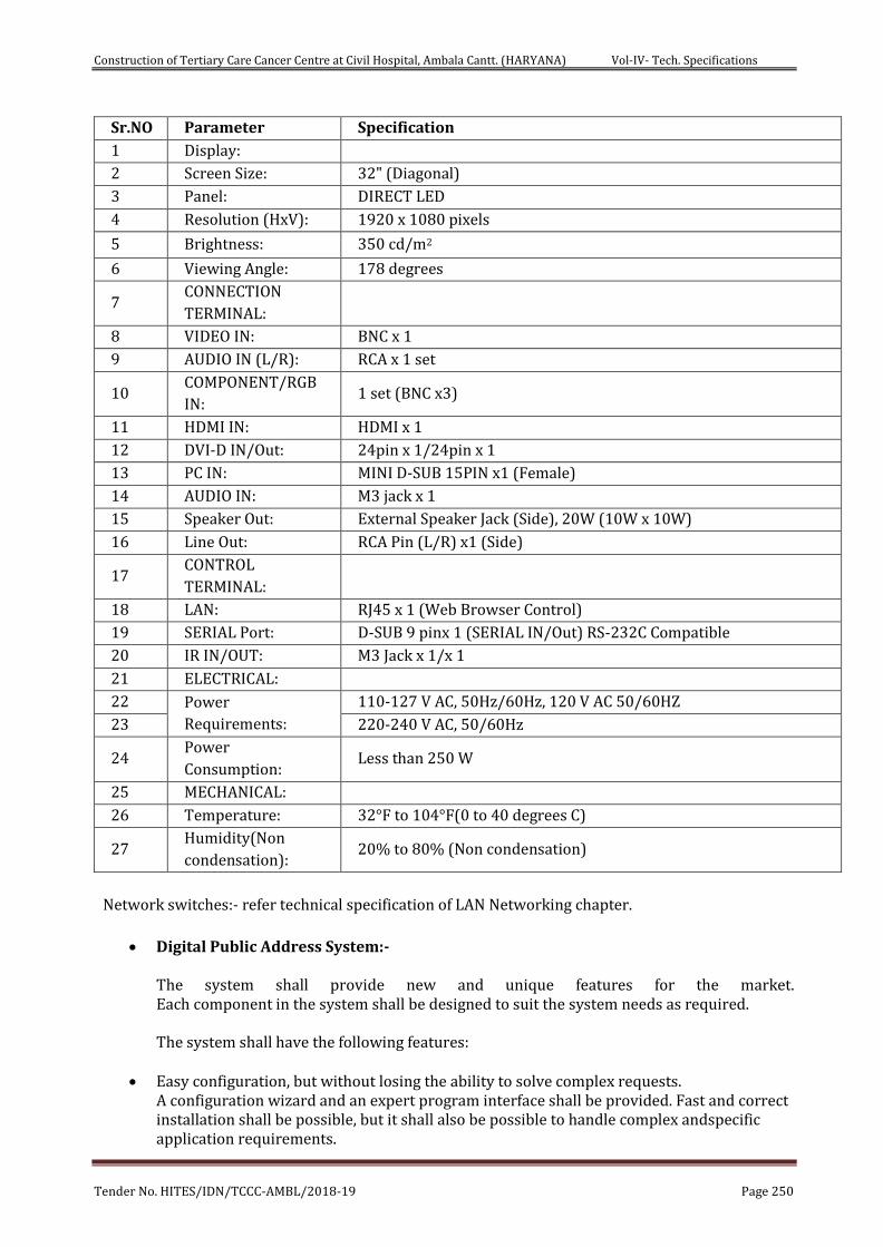
Construction of Tertiary Care Cancer Centre at Civil Hospital, Ambala Cantt. (HARYANA) Vol-IV- Tech. Specifications
Tender No. HITES/IDN/TCCC-AMBL/2018-19 Page 250
Sr.NO Parameter Specification
1 Display:
2 Screen Size: 32" (Diagonal)
3 Panel: DIRECT LED
4 Resolution (HxV): 1920 x 1080 pixels
5 Brightness: 350 cd/m2
6 Viewing Angle: 178 degrees
7 CONNECTION
TERMINAL:
8 VIDEO IN: BNC x 1
9 AUDIO IN (L/R): RCA x 1 set
10 COMPONENT/RGB
IN: 1 set (BNC x3)
11 HDMI IN: HDMI x 1
12 DVI-D IN/Out: 24pin x 1/24pin x 1
13 PC IN: MINI D-SUB 15PIN x1 (Female)
14 AUDIO IN: M3 jack x 1
15 Speaker Out: External Speaker Jack (Side), 20W (10W x 10W)
16 Line Out: RCA Pin (L/R) x1 (Side)
17 CONTROL
TERMINAL:
18 LAN: RJ45 x 1 (Web Browser Control)
19 SERIAL Port: D-SUB 9 pinx 1 (SERIAL IN/Out) RS-232C Compatible
20 IR IN/OUT: M3 Jack x 1/x 1
21 ELECTRICAL:
22 Power
Requirements:
110-127 V AC, 50Hz/60Hz, 120 V AC 50/60HZ
23 220-240 V AC, 50/60Hz
24 Power
Consumption: Less than 250 W
25 MECHANICAL:
26 Temperature: 32°F to 104°F(0 to 40 degrees C)
27 Humidity(Non
condensation): 20% to 80% (Non condensation)
Network switches:- refer technical specification of LAN Networking chapter.
Digital Public Address System:-
The system shall provide new and unique features for the market. Each component in the system shall be designed to suit the system needs as required.
The system shall have the following features:
Easy configuration, but without losing the ability to solve complex requests.
A configuration wizard and an expert program interface shall be provided. Fast and correct installation shall be possible, but it shall also be possible to handle complex andspecific application requirements.
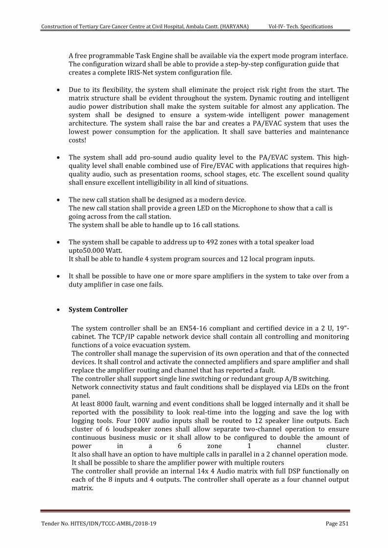
Construction of Tertiary Care Cancer Centre at Civil Hospital, Ambala Cantt. (HARYANA) Vol-IV- Tech. Specifications
Tender No. HITES/IDN/TCCC-AMBL/2018-19 Page 251
A free programmable Task Engine shall be available via the expert mode program interface. The configuration wizard shall be able to provide a step-by-step configuration guide that creates a complete IRIS-Net system configuration file.
Due to its flexibility, the system shall eliminate the project risk right from the start. The matrix structure shall be evident throughout the system. Dynamic routing and intelligent audio power distribution shall make the system suitable for almost any application. The system shall be designed to ensure a system-wide intelligent power management architecture. The system shall raise the bar and creates a PA/EVAC system that uses the lowest power consumption for the application. It shall save batteries and maintenance costs!
The system shall add pro-sound audio quality level to the PA/EVAC system. This high-
quality level shall enable combined use of Fire/EVAC with applications that requires high-quality audio, such as presentation rooms, school stages, etc. The excellent sound quality shall ensure excellent intelligibility in all kind of situations.
The new call station shall be designed as a modern device.
The new call station shall provide a green LED on the Microphone to show that a call is going across from the call station. The system shall be able to handle up to 16 call stations.
The system shall be capable to address up to 492 zones with a total speaker load
upto50.000 Watt. It shall be able to handle 4 system program sources and 12 local program inputs.
It shall be possible to have one or more spare amplifiers in the system to take over from a duty amplifier in case one fails.
System Controller
The system controller shall be an EN54-16 compliant and certified device in a 2 U, 19”-cabinet. The TCP/IP capable network device shall contain all controlling and monitoring functions of a voice evacuation system. The controller shall manage the supervision of its own operation and that of the connected devices. It shall control and activate the connected amplifiers and spare amplifier and shall replace the amplifier routing and channel that has reported a fault. The controller shall support single line switching or redundant group A/B switching. Network connectivity status and fault conditions shall be displayed via LEDs on the front panel. At least 8000 fault, warning and event conditions shall be logged internally and it shall be reported with the possibility to look real-time into the logging and save the log with logging tools. Four 100V audio inputs shall be routed to 12 speaker line outputs. Each cluster of 6 loudspeaker zones shall allow separate two-channel operation to ensure continuous business music or it shall allow to be configured to double the amount of power in a 6 zone 1 channel cluster. It also shall have an option to have multiple calls in parallel in a 2 channel operation mode. It shall be possible to share the amplifier power with multiple routers The controller shall provide an internal 14x 4 Audio matrix with full DSP functionally on each of the 8 inputs and 4 outputs. The controller shall operate as a four channel output matrix.
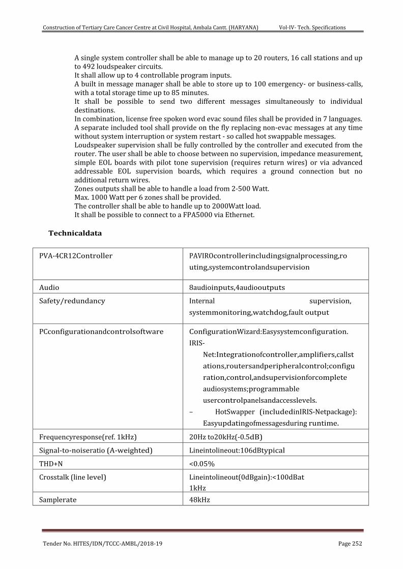
Construction of Tertiary Care Cancer Centre at Civil Hospital, Ambala Cantt. (HARYANA) Vol-IV- Tech. Specifications
Tender No. HITES/IDN/TCCC-AMBL/2018-19 Page 252
A single system controller shall be able to manage up to 20 routers, 16 call stations and up to 492 loudspeaker circuits. It shall allow up to 4 controllable program inputs. A built in message manager shall be able to store up to 100 emergency- or business-calls, with a total storage time up to 85 minutes. It shall be possible to send two different messages simultaneously to individual destinations. In combination, license free spoken word evac sound files shall be provided in 7 languages. A separate included tool shall provide on the fly replacing non-evac messages at any time without system interruption or system restart - so called hot swappable messages. Loudspeaker supervision shall be fully controlled by the controller and executed from the router. The user shall be able to choose between no supervision, impedance measurement, simple EOL boards with pilot tone supervision (requires return wires) or via advanced addressable EOL supervision boards, which requires a ground connection but no additional return wires. Zones outputs shall be able to handle a load from 2-500 Watt. Max. 1000 Watt per 6 zones shall be provided. The controller shall be able to handle up to 2000Watt load. It shall be possible to connect to a FPA5000 via Ethernet.
Technicaldata
PVA-4CR12Controller PAVIROcontrollerincludingsignalprocessing,ro
uting,systemcontrolandsupervision
Audio 8audioinputs,4audiooutputs
Safety/redundancy Internal supervision,
systemmonitoring,watchdog,fault output
PCconfigurationandcontrolsoftware ConfigurationWizard:Easysystemconfiguration.
IRIS-
Net:Integrationofcontroller,amplifiers,callst
ations,routersandperipheralcontrol;configu
ration,control,andsupervisionforcomplete
audiosystems;programmable
usercontrolpanelsandaccesslevels.
– HotSwapper (includedinIRIS-Netpackage):
Easyupdatingofmessagesduring runtime.
Frequencyresponse(ref. 1kHz) 20Hz to20kHz(-0.5dB)
Signal-to-noiseratio (A-weighted) Lineintolineout:106dBtypical
THD+N <0.05%
Crosstalk (line level) Lineintolineout(0dBgain):<100dBat
1kHz
Samplerate 48kHz
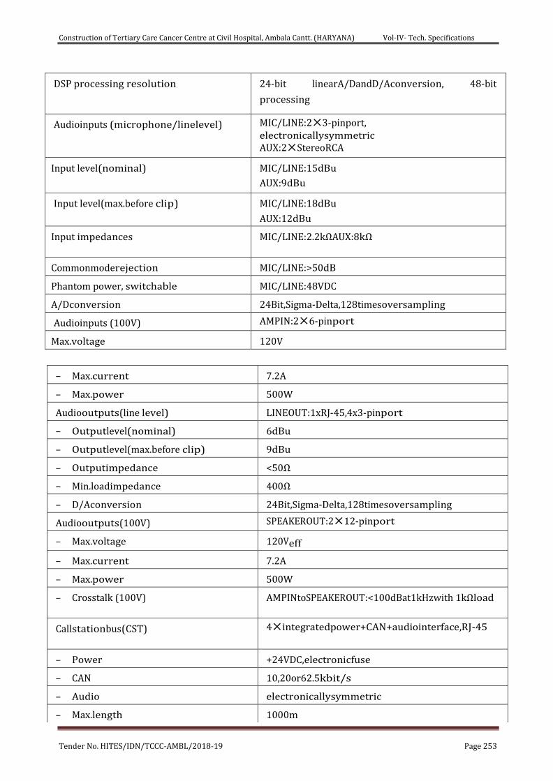
Construction of Tertiary Care Cancer Centre at Civil Hospital, Ambala Cantt. (HARYANA) Vol-IV- Tech. Specifications
Tender No. HITES/IDN/TCCC-AMBL/2018-19 Page 253
DSP processing resolution 24-bit linearA/DandD/Aconversion, 48-bit
processing
Audioinputs (microphone/linelevel) MIC/LINE:23-pinport, electronicallysymmetric AUX:2StereoRCA
Input level(nominal) MIC/LINE:15dBu
AUX:9dBu
Input level(max.before clip) MIC/LINE:18dBu
AUX:12dBu
Input impedances MIC/LINE:2.2kΩAUX:8kΩ
Commonmoderejection MIC/LINE:>50dB
Phantom power, switchable MIC/LINE:48VDC
A/Dconversion 24Bit,Sigma-Delta,128timesoversampling
Audioinputs (100V) AMPIN:26-pinport
Max.voltage 120V
– Max.current 7.2A
– Max.power 500W
Audiooutputs(line level) LINEOUT:1xRJ-45,4x3-pinport
– Outputlevel(nominal) 6dBu
– Outputlevel(max.before clip) 9dBu
– Outputimpedance <50Ω
– Min.loadimpedance 400Ω
– D/Aconversion 24Bit,Sigma-Delta,128timesoversampling
Audiooutputs(100V) SPEAKEROUT:212-pinport
– Max.voltage 120Veff
– Max.current 7.2A
– Max.power 500W
– Crosstalk (100V) AMPINtoSPEAKEROUT:<100dBat1kHzwith 1kΩload
Callstationbus(CST) 4integratedpower+CAN+audiointerface,RJ-45
– Power +24VDC,electronicfuse
– CAN 10,20or62.5kbit/s
– Audio electronicallysymmetric
– Max.length 1000m
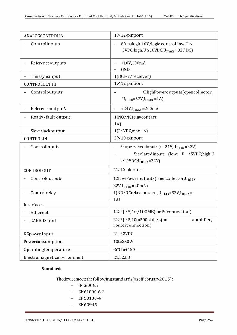
Construction of Tertiary Care Cancer Centre at Civil Hospital, Ambala Cantt. (HARYANA) Vol-IV- Tech. Specifications
Tender No. HITES/IDN/TCCC-AMBL/2018-19 Page 254
– Controlinputs – 5supervised inputs (0–24V,Umax =32V)
– 5isolatedinputs (low: U ≤5VDC;high:U
≥10VDC;Umax=32V)
CONTROLOUT 210-pinport
– Controloutputs 12LowPoweroutputs(opencollector,Umax =
32V,Imax =40mA)
– Controlrelay 1(NO/NCrelaycontacts,Umax=32V,Imax=
1A) Interfaces
– Ethernet 1RJ-45,10/100MB(for PCconnection)
– CANBUS port 2RJ-45,10to500kbit/s(for amplifier, routerconnection)
DCpower input 21–32VDC
Powerconsumption 10to250W
Operatingtemperature -5°Cto+45°C
Electromagneticenvironment E1,E2,E3
Standards
Thedevicemeetsthefollowingstandards(asofFebruary2015):
– IEC60065
– EN61000-6-3
– EN50130-4
– EN60945
ANALOGCONTROLIN 112-pinport
– Controlinputs – 8(analog0-10V/logic control;low:U ≤
5VDC;high:U ≥10VDC;Umax =32V DC)
– Referenceoutputs – +10V,100mA
– GND
– Timesyncinput 1(DCF-77receiver)
CONTROLOUT HP 112-pinport
– Controloutputs – 6HighPoweroutputs(opencollector,
Umax=32V,Imax =1A)
– ReferenceoutputV – +24V,Imax =200mA
– Ready/fault output 1(NO/NCrelaycontact
1A)
– Slaveclockoutput 1(24VDC,max.1A)
CONTROLIN 210-pinport
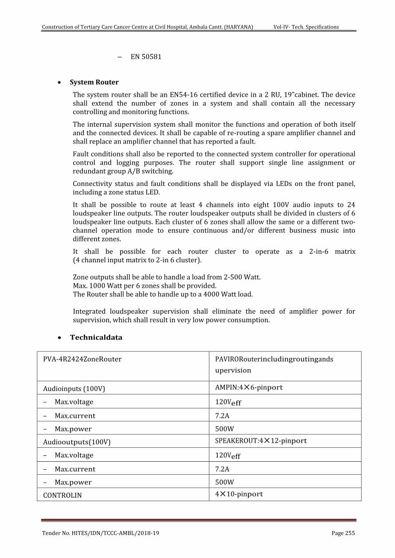
Construction of Tertiary Care Cancer Centre at Civil Hospital, Ambala Cantt. (HARYANA) Vol-IV- Tech. Specifications
Tender No. HITES/IDN/TCCC-AMBL/2018-19 Page 255
– EN 50581
System Router
The system router shall be an EN54-16 certified device in a 2 RU, 19”cabinet. The device shall extend the number of zones in a system and shall contain all the necessary controlling and monitoring functions.
The internal supervision system shall monitor the functions and operation of both itself and the connected devices. It shall be capable of re-routing a spare amplifier channel and shall replace an amplifier channel that has reported a fault.
Fault conditions shall also be reported to the connected system controller for operational control and logging purposes. The router shall support single line assignment or redundant group A/B switching.
Connectivity status and fault conditions shall be displayed via LEDs on the front panel, including a zone status LED.
It shall be possible to route at least 4 channels into eight 100V audio inputs to 24 loudspeaker line outputs. The router loudspeaker outputs shall be divided in clusters of 6 loudspeaker line outputs. Each cluster of 6 zones shall allow the same or a different two-channel operation mode to ensure continuous and/or different business music into different zones.
It shall be possible for each router cluster to operate as a 2-in-6 matrix (4 channel input matrix to 2-in 6 cluster). Zone outputs shall be able to handle a load from 2-500 Watt. Max. 1000 Watt per 6 zones shall be provided. The Router shall be able to handle up to a 4000 Watt load. Integrated loudspeaker supervision shall eliminate the need of amplifier power for supervision, which shall result in very low power consumption.
Technicaldata
PVA-4R2424ZoneRouter PAVIRORouterincludingroutingands
upervision
Audioinputs (100V) AMPIN:46-pinport
– Max.voltage 120Veff
– Max.current 7.2A
– Max.power 500W
Audiooutputs(100V) SPEAKEROUT:412-pinport
– Max.voltage 120Veff
– Max.current 7.2A
– Max.power 500W
CONTROLIN 410-pinport
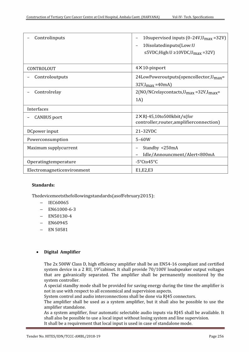
Construction of Tertiary Care Cancer Centre at Civil Hospital, Ambala Cantt. (HARYANA) Vol-IV- Tech. Specifications
Tender No. HITES/IDN/TCCC-AMBL/2018-19 Page 256
– Controlinputs – 10supervised inputs (0–24V,Umax =32V)
– 10isolatedinputs(Low:U
≤5VDC;High:U ≥10VDC,Umax =32V)
CONTROLOUT 410-pinport
– Controloutputs 24LowPoweroutputs(opencollector,Umax=
32V,Imax =40mA)
– Controlrelay 2(NO/NCrelaycontacts,Umax =32V,Imax=
1A)
Interfaces
– CANBUS port 2RJ-45,10to500kbit/s(for controller,router,amplifierconnection)
DCpower input 21–32VDC
Powerconsumption 5–60W
Maximum supplycurrent – Standby <250mA
– Idle/Announcment/Alert<800mA
Operatingtemperature -5°Cto45°C
Electromagneticenvironment E1,E2,E3
Standards: Thedevicemeetsthefollowingstandards(asofFebruary2015):
– IEC60065
– EN61000-6-3
– EN50130-4
– EN60945
– EN 50581
Digital Amplifier
The 2x 500W Class D, high efficiency amplifier shall be an EN54-16 compliant and certified system device in a 2 RU, 19”cabinet. It shall provide 70/100V loudspeaker output voltages that are galvanically separated. The amplifier shall be permanently monitored by the system controller. A special standby mode shall be provided for saving energy during the time the amplifier is not in use with respect to all economical and supervision aspects. System control and audio interconnections shall be done via RJ45 connectors. The amplifier shall be used as a system amplifier, but it shall also be possible to use the amplifier standalone. As a system amplifier, four automatic selectable audio inputs via RJ45 shall be available. It shall also be possible to use a local input without losing system and line supervision. It shall be a requirement that local input is used in case of standalone mode.
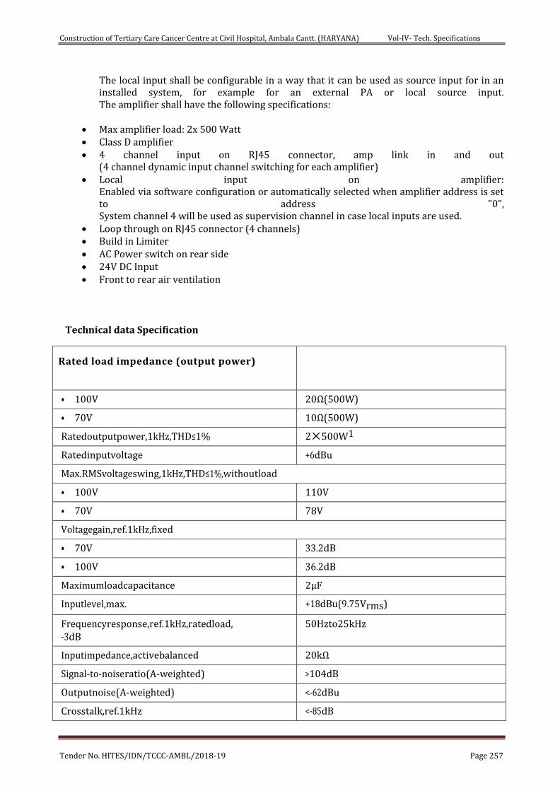
Construction of Tertiary Care Cancer Centre at Civil Hospital, Ambala Cantt. (HARYANA) Vol-IV- Tech. Specifications
Tender No. HITES/IDN/TCCC-AMBL/2018-19 Page 257
The local input shall be configurable in a way that it can be used as source input for in an installed system, for example for an external PA or local source input. The amplifier shall have the following specifications:
Max amplifier load: 2x 500 Watt Class D amplifier 4 channel input on RJ45 connector, amp link in and out
(4 channel dynamic input channel switching for each amplifier) Local input on amplifier:
Enabled via software configuration or automatically selected when amplifier address is set to address "0", System channel 4 will be used as supervision channel in case local inputs are used.
Loop through on RJ45 connector (4 channels) Build in Limiter AC Power switch on rear side 24V DC Input Front to rear air ventilation
Technical data Specification
Rated load impedance (output power)
• 100V 20Ω(500W)
• 70V 10Ω(500W)
Ratedoutputpower,1kHz,THD≤1% 2500W1
Ratedinputvoltage +6dBu
Max.RMSvoltageswing,1kHz,THD≤1%,withoutload
• 100V 110V
• 70V 78V
Voltagegain,ref.1kHz,fixed
• 70V 33.2dB
• 100V 36.2dB
Maximumloadcapacitance 2µF
Inputlevel,max. +18dBu(9.75Vrms)
Frequencyresponse,ref.1kHz,ratedload, -3dB
50Hzto25kHz
Inputimpedance,activebalanced 20kΩ
Signal-to-noiseratio(A-weighted) >104dB
Outputnoise(A-weighted) <-62dBu
Crosstalk,ref.1kHz <-85dB
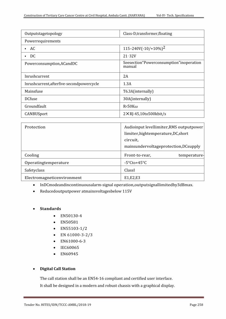
Construction of Tertiary Care Cancer Centre at Civil Hospital, Ambala Cantt. (HARYANA) Vol-IV- Tech. Specifications
Tender No. HITES/IDN/TCCC-AMBL/2018-19 Page 258
Outputstagetopology Class-D,transformer,floating
Powerrequirements
• AC 115–240V(-10/+10%)2
• DC 21‑32V
Powerconsumption,ACandDC Seesection“Powerconsumption”inoperationmanual
Inrushcurrent 2A
Inrushcurrent,afterfive-secondpowercycle 1.3A
Mainsfuse T6.3A(internally)
DCfuse 30A(internally)
Groundfault R<50Kω
CANBUSport 2RJ-45,10to500kbit/s
Protection Audioinput levellimiter,RMS outputpower
limiter,hightemperature,DC,short
circuit,
mainsundervoltageprotection,DCsupply
undervoltageprotection,inrushcurrentli
miter,ground fault Cooling Front-to-rear, temperature-
controlledfans Operatingtemperature -5°Cto+45°C
Safetyclass ClassI
Electromagneticenvironment E1,E2,E3
InDCmodeandincontinuousalarm-signal operation,outputsignallimitedby3dBmax.
Reducedoutputpower atmainsvoltagesbelow 115V
Standards
EN50130-4
EN50581
EN55103-1/2
EN 61000-3-2/3
EN61000-6-3
IEC60065
EN60945
Digital Call Station
The call station shall be an EN54-16 compliant and certified user interface.
It shall be designed in a modern and robust chassis with a graphical display.
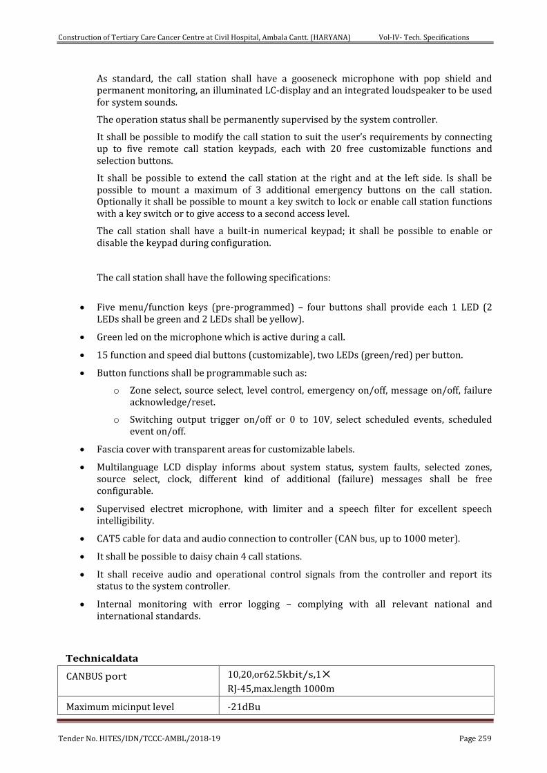
Construction of Tertiary Care Cancer Centre at Civil Hospital, Ambala Cantt. (HARYANA) Vol-IV- Tech. Specifications
Tender No. HITES/IDN/TCCC-AMBL/2018-19 Page 259
As standard, the call station shall have a gooseneck microphone with pop shield and permanent monitoring, an illuminated LC-display and an integrated loudspeaker to be used for system sounds.
The operation status shall be permanently supervised by the system controller.
It shall be possible to modify the call station to suit the user’s requirements by connecting up to five remote call station keypads, each with 20 free customizable functions and selection buttons.
It shall be possible to extend the call station at the right and at the left side. Is shall be possible to mount a maximum of 3 additional emergency buttons on the call station. Optionally it shall be possible to mount a key switch to lock or enable call station functions with a key switch or to give access to a second access level.
The call station shall have a built-in numerical keypad; it shall be possible to enable or disable the keypad during configuration.
The call station shall have the following specifications:
Five menu/function keys (pre-programmed) – four buttons shall provide each 1 LED (2 LEDs shall be green and 2 LEDs shall be yellow).
Green led on the microphone which is active during a call.
15 function and speed dial buttons (customizable), two LEDs (green/red) per button.
Button functions shall be programmable such as:
o Zone select, source select, level control, emergency on/off, message on/off, failure acknowledge/reset.
o Switching output trigger on/off or 0 to 10V, select scheduled events, scheduled event on/off.
Fascia cover with transparent areas for customizable labels.
Multilanguage LCD display informs about system status, system faults, selected zones, source select, clock, different kind of additional (failure) messages shall be free configurable.
Supervised electret microphone, with limiter and a speech filter for excellent speech intelligibility.
CAT5 cable for data and audio connection to controller (CAN bus, up to 1000 meter).
It shall be possible to daisy chain 4 call stations.
It shall receive audio and operational control signals from the controller and report its status to the system controller.
Internal monitoring with error logging – complying with all relevant national and international standards.
Technicaldata
CANBUS port 10,20,or62.5kbit/s,1
RJ-45,max.length 1000m
Maximum micinput level -21dBu
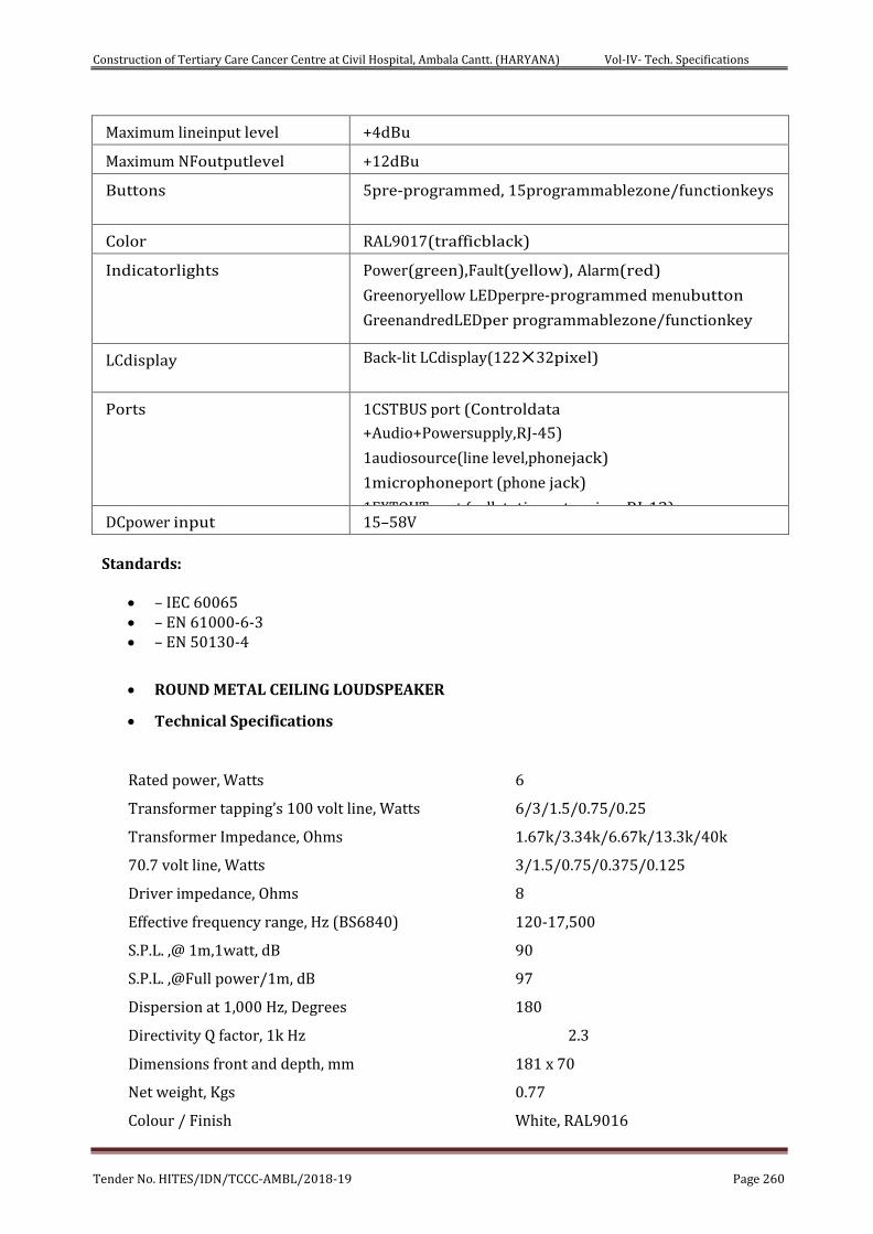
Construction of Tertiary Care Cancer Centre at Civil Hospital, Ambala Cantt. (HARYANA) Vol-IV- Tech. Specifications
Tender No. HITES/IDN/TCCC-AMBL/2018-19 Page 260
Maximum lineinput level +4dBu
Maximum NFoutputlevel +12dBu
Buttons 5pre-programmed, 15programmablezone/functionkeys
Color RAL9017(trafficblack)
Indicatorlights Power(green),Fault(yellow), Alarm(red)
Greenoryellow LEDperpre-programmed menubutton
GreenandredLEDper programmablezone/functionkey
LCdisplay Back-lit LCdisplay(12232pixel)
Ports 1CSTBUS port (Controldata
+Audio+Powersupply,RJ-45)
1audiosource(line level,phonejack)
1microphoneport (phone jack)
1EXTOUT port (callstationextension, RJ-12) DCpower input 15–58V
Standards:
– IEC 60065 – EN 61000-6-3 – EN 50130-4
ROUND METAL CEILING LOUDSPEAKER
Technical Specifications
Rated power, Watts 6
Transformer tapping’s 100 volt line, Watts 6/3/1.5/0.75/0.25
Transformer Impedance, Ohms 1.67k/3.34k/6.67k/13.3k/40k
70.7 volt line, Watts 3/1.5/0.75/0.375/0.125
Driver impedance, Ohms 8
Effective frequency range, Hz (BS6840) 120-17,500
S.P.L. ,@ 1m,1watt, dB 90
S.P.L. ,@Full power/1m, dB 97
Dispersion at 1,000 Hz, Degrees 180
Directivity Q factor, 1k Hz 2.3
Dimensions front and depth, mm 181 x 70
Net weight, Kgs 0.77
Colour / Finish White, RAL9016
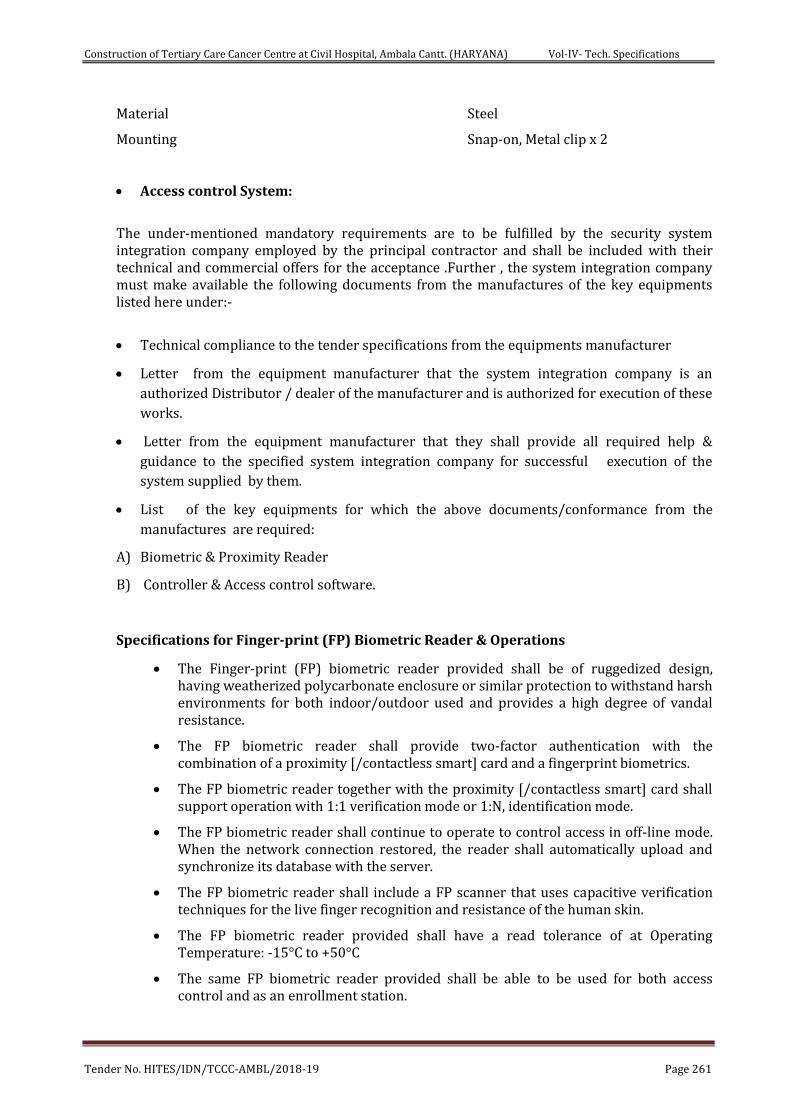
Construction of Tertiary Care Cancer Centre at Civil Hospital, Ambala Cantt. (HARYANA) Vol-IV- Tech. Specifications
Tender No. HITES/IDN/TCCC-AMBL/2018-19 Page 261
Material Steel
Mounting Snap-on, Metal clip x 2
Access control System:
The under-mentioned mandatory requirements are to be fulfilled by the security system integration company employed by the principal contractor and shall be included with their technical and commercial offers for the acceptance .Further , the system integration company must make available the following documents from the manufactures of the key equipments listed here under:-
Technical compliance to the tender specifications from the equipments manufacturer
Letter from the equipment manufacturer that the system integration company is an
authorized Distributor / dealer of the manufacturer and is authorized for execution of these
works.
Letter from the equipment manufacturer that they shall provide all required help &
guidance to the specified system integration company for successful execution of the
system supplied by them.
List of the key equipments for which the above documents/conformance from the
manufactures are required:
A) Biometric & Proximity Reader
B) Controller & Access control software.
Specifications for Finger-print (FP) Biometric Reader & Operations
The Finger-print (FP) biometric reader provided shall be of ruggedized design, having weatherized polycarbonate enclosure or similar protection to withstand harsh environments for both indoor/outdoor used and provides a high degree of vandal resistance.
The FP biometric reader shall provide two-factor authentication with the combination of a proximity [/contactless smart] card and a fingerprint biometrics.
The FP biometric reader together with the proximity [/contactless smart] card shall support operation with 1:1 verification mode or 1:N, identification mode.
The FP biometric reader shall continue to operate to control access in off-line mode. When the network connection restored, the reader shall automatically upload and synchronize its database with the server.
The FP biometric reader shall include a FP scanner that uses capacitive verification techniques for the live finger recognition and resistance of the human skin.
The FP biometric reader provided shall have a read tolerance of at Operating Temperature: -15°C to +50°C
The same FP biometric reader provided shall be able to be used for both access control and as an enrollment station.
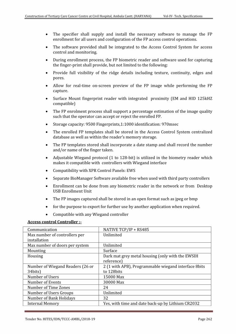
Construction of Tertiary Care Cancer Centre at Civil Hospital, Ambala Cantt. (HARYANA) Vol-IV- Tech. Specifications
Tender No. HITES/IDN/TCCC-AMBL/2018-19 Page 262
The specifier shall supply and install the necessary software to manage the FP enrollment for all users and configuration of the FP access control operations.
The software provided shall be integrated to the Access Control System for access control and monitoring.
During enrollment process, the FP biometric reader and software used for capturing the finger-print shall provide, but not limited to the following:
Provide full visibility of the ridge details including texture, continuity, edges and pores.
Allow for real-time on-screen preview of the FP image while performing the FP capture.
Surface Mount fingerprint reader with integrated proximity (EM and HID 125kHZ compatible)
The FP enrolment process shall support a percentage estimation of the image quality such that the operator can accept or reject the enrolled FP.
Storage capacity: 9500 Fingerprints,1:1000 identification: 970msec
The enrolled FP templates shall be stored in the Access Control System centralized database as well as within the reader’s memory storage.
The FP templates stored shall incorporate a date stamp and shall record the number and/or name of the finger taken.
Adjustable Wiegand protocol (1 to 128-bit) is utilized in the biometry reader which makes it compatible with controllers with Wiegand interface
Compatibility with XPR Control Panels: EWS
Separate BioManager Software available free when used with third party controllers
Enrollment can be done from any biometric reader in the network or from Desktop USB Enrollment Unit
The FP images captured shall be stored in an open format such as jpeg or bmp
for the purpose to export for further use by another application when required.
Compatible with any Wiegand controller
Access control Controller :-
Communication NATIVE TCP/IP + RS485 Max number of controllers per installation
Unlimited
Max number of doors per system Unlimited Mounting Surface Housing Dark mat grey metal housing (only with the EWSIH
reference) Number of Wiegand Readers (26 or 34bits)
2 (1 with APB), Programmable wiegand interface 8bits to 128bits
Number of Users 15000 Max Number of Events 30000 Max Number of Time Zones 24 Number of Users Groups Unlimited Number of Bank Holidays 32 Internal Memory Yes, with time and date back-up by Lithium CR2032
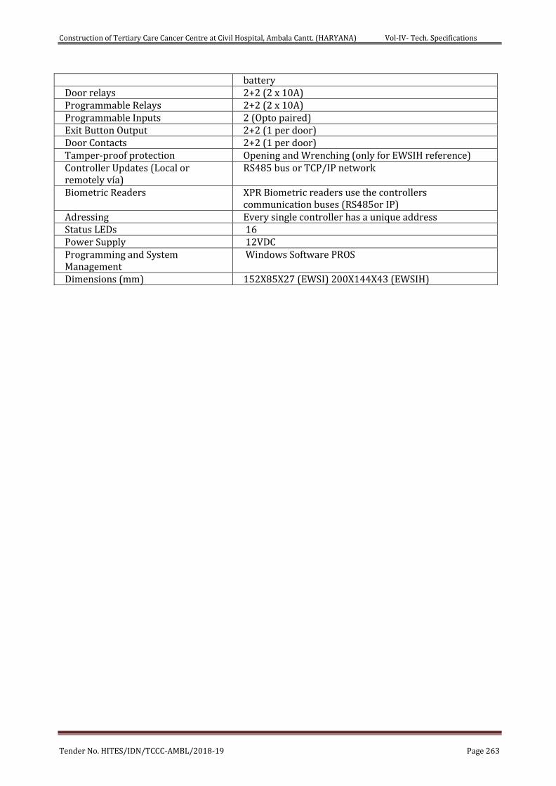
Construction of Tertiary Care Cancer Centre at Civil Hospital, Ambala Cantt. (HARYANA) Vol-IV- Tech. Specifications
Tender No. HITES/IDN/TCCC-AMBL/2018-19 Page 263
battery Door relays 2+2 (2 x 10A) Programmable Relays 2+2 (2 x 10A) Programmable Inputs 2 (Opto paired) Exit Button Output 2+2 (1 per door) Door Contacts 2+2 (1 per door) Tamper-proof protection Opening and Wrenching (only for EWSIH reference) Controller Updates (Local or remotely vía)
RS485 bus or TCP/IP network
Biometric Readers XPR Biometric readers use the controllers communication buses (RS485or IP)
Adressing Every single controller has a unique address Status LEDs 16 Power Supply 12VDC Programming and System Management
Windows Software PROS
Dimensions (mm) 152X85X27 (EWSI) 200X144X43 (EWSIH)
Construction of Tertiary Care Cancer Centre at Civil Hospital, Ambala Cantt. (HARYANA) Vol-IV- Tech. Specifications
Tender No. HITES/IDN/TCCC-AMBL/2018-19 Page 264
CHAPTER-13
TECHNICAL SPECIFICATION SOLAR POWER
WORK DESCRIPTION-GENERAL
This section specifies the engineering, supply, delivery to site, installation, testing, commissioning and maintenance of solar power plant as described in the Content.
SOLAR PHOTOVOLTAIC MODULES:
The total Solar PV minimum array capacity should not be less than the KWp specified for each location as above and should comprise of poly crystalline modules of minimum 250 Wp and above wattage. Module capacity less than minimum 250 Wp should not be supplied. The Photovoltaic module must be tested and certified by an independent testing laboratory that is accredited in accordance with ISO Guide 25.
a. The PV modules should be of Indigenous make. The PV modules must conform to the latest edition of any of the following / equivalent BIS standards for PV module design qualification and type approval:
Crystalline Silicon Terrestrial PV Modules IEC 61215 / IS14286
Thin Film Terrestrial PV Modules IEC 61646 / Equivalent IS
In addition, the modules must conform to IEC 61730 Part 1(requirements for Construction) & Part 2 (requirements for testing, for safety qualification).
Further, the PV modules must also qualify the Salt Mist Corrosion Testing as per IEC61701 / IS 61701
b. SPV module Conversion efficiency should be equal to or greater than 14% at STC and AM 1.5 radiations.
c. The PV modules shall perform satisfactorily in humidity up to 100 % with temperature between -40ºC to +85ºC. Since the modules would be used in a high voltage circuit, the high voltage insulation test shall be carried out on each module and a test certificate to that effect be provided.
d. The prescribed electrical degradation shall not be less than 10 (ten) percent of the full rated original output at the end of the period of 12 years and not less than 20 (twenty) percent of the full rated original output at the end of 25 years.
e. Manufacturers/suppliers should confirm whether they are supplying PV modules using a RF identification tag (RFID), which must contain the following information. The RFID can be placed inside or outside the module laminate, but must be able to withstand harsh environmental conditions:-
i. Name & Serial No. of the Manufacturer of PV Module.
ii. Name & Serial No. of the Manufacturer of Solar Cells
iii. Month and year of the manufacture ( separately for solar cells & module)
iv. Country of origin (separately for solar cells & module)
v. I – V curve for the module
Construction of Tertiary Care Cancer Centre at Civil Hospital, Ambala Cantt. (HARYANA) Vol-IV- Tech. Specifications
Tender No. HITES/IDN/TCCC-AMBL/2018-19 Page 265
vi. Peak Wattage, Im, Vm and FF for the module
vii. Unique Serial No. and Model No. of the module
viii. Date and year of obtaining IEC PV module qualification certificate
ix. Name of the test lab issuing IEC certificate
x. Other relevant information on traceability of solar cells and module as per ISO9000 series.
f. Other general requirement for the PV modules and subsystems shall be the following:
i. Raw material (Solar cells) and technology employed in the module production shall have to be certified and a certificate giving details of major materials i.e. cells, Glass, back sheet, their makes and data sheets to be submitted for the modules being supplied by the bidder.
ii. The rated output power of any supplied module shall not have negative tolerance.
iii. The peak-power point voltage and the peak-power point current of any supplied module and/or any module string (series connected modules) shall not vary more than 3 (three) percent from the respective arithmetic means for all modules and/or for all module string, as the case may be
iv. Except where specified, the front module surface shall consist of impact resistant, low-iron and high-transmission toughened glass.
v. The module frame, if any, shall be made of aluminum or corrosion-resistant material which shall be electrolytically compatible with the structural material used for mounting the modules.
vi. The module shall be provided with a junction box with either provision of external screw terminal connection or sealed type and with arrangement for provision of by-pass diode. The box shall have hinged, weather proof lid with captive screws and cable gland entry points or may be of sealed type IP65 rated.
vii. Necessary I-V curves at 250 C, 450,600 and at NOC are required to be furnished.
viii. Fill factor of module shall not be less than 0.70
ARRAY STRUCTURE:
a. The array structure shall be so designed that it will occupy minimum space without scarifying the output from SPV panels.
b. Wherever required, suitable number of PV panel structure shall be provided. Structures shall be of flat-plate design either or L sections.
c. Structural material shall be corrosion resistant and electrolytically compatible with the material used in the module frame, its fasteners, nuts and bolts. Galvanizing should meet ASTM A-123 hot dipped galvanizing or equivalent which provides at least spraying thickness of 70 micron on steel as per IS 5905, if steel
Construction of Tertiary Care Cancer Centre at Civil Hospital, Ambala Cantt. (HARYANA) Vol-IV- Tech. Specifications
Tender No. HITES/IDN/TCCC-AMBL/2018-19 Page 266
frame is used. Aluminum frame structures with adequate strength and in accordance with relevant BIS/international standards can also be used.
d. Structures shall be supplied complete with all members to be compatible for allowing easy installation at the roof top site and the structure atop sloping roofs shall be done by the Bidder.
e. The structures shall be designed to allow easy replacement of any module & can be either designed to transfer point load on the roof top or UDL as per site conditions and design to be approved by DGHS/HITES.
f. Each structure shall have a provision to adjust its angle of inclination to the horizontal as per the site conditions.
g. The array structure shall be grounded properly using maintenance free earthing kit.
h. Each panel frame structure should be so fabricated as to be fixed on the rooftop column/wall structures. The structure should be capable of withstanding a wind load of 200 km/hr. after grouting & installation. The front end of the solar array must be one meter above the rooftop. Grouting material for SPV structures shall be as per M15 (1:2:4) concrete specifications.
i. The structures shall be designed for simple mechanical and electrical installation. There shall be no requirement of welding or complex machinery at the installation site. If prior civil work or support platform is absolutely essential to install the structures, the supplier shall clearly and unambiguously communicate such requirements along with their specification in the bid. Detailed engineering drawings and instructions for such prior civil work shall be carried out prior to the supply of Goods.
j. The supplier shall specify installation details of the PV modules and the support structures with appropriate diagrams and drawings. Such details shall include, but not limited to, the following:
i. Determination of true south at the site;
ii. Array tilt angle to the horizontal, with permitted tolerance;
iii. Details with drawings for fixing the modules;
iv. Details with drawings of fixing the junction/terminal boxes;
v. Interconnections details inside the junction/terminal boxes;
vi. Structural installation details and drawings;
vii. Electrical grounding (earthing);
viii. Inter-panel/Inter-row distance with allowed tolerances; and
ix. Safety precautions to be taken.
k. The array structure shall support SPV modules at a given orientation and absorb and transfer the mechanical loads to the rooftop columns properly. All nuts and bolts shall be of very good quality stainless steel. Detailed design and drawing shall have to be submitted for acceptance and approval before execution of work.
NOTE: The structural design of the complete system should be compatible with the structural strength and load bearing capacity of the roof. Design calculations and
Construction of Tertiary Care Cancer Centre at Civil Hospital, Ambala Cantt. (HARYANA) Vol-IV- Tech. Specifications
Tender No. HITES/IDN/TCCC-AMBL/2018-19 Page 267
certificate to this effect shall be provided by a qualified chartered structural engineer.
POWER CONDITIONING UNIT (PCU)
The PCU required of appropriate capacities as follows, should convert DC power produced by SPV modules, in to AC power and adjust the voltage & frequency levels to suit the local grid conditions.
PCU should be appropriate capacity of proposed solar PV plants.
POWER CONDITIONING UNIT (INVERTER PLUS MPPT CHARGE CONTROLLER)
Input Voltage:
• From PV Module: Minimum 08KWp, 120V nominal DC from Solar PV Array.
• From AC source: 410-415V (Phase to Phase) (+12%, - 20%), 3 ph, 50 Hz (+ .5 Hz).
Output Voltage:
Suitable for charging 120 V, 600AH tubular plate lead acid VRLA Gel type battery bank.
Protection:
• Short Circuit
• Deep discharge
• Over charging (Automatic trickle charge mode on full charge)
• Input surge voltage
• Over current (Load)
• Battery reverse polarity
• Solar Array reverse polarity
Indication (LED/LCD Indication):
• String on
• Mains on
• Input on
• Control on
• Charge on
• 80% charged, 100% charged
• Charger overload
• Battery on trickle
• Battery disconnected/fault battery reverse polarity
• Low solar power
• System fault
Construction of Tertiary Care Cancer Centre at Civil Hospital, Ambala Cantt. (HARYANA) Vol-IV- Tech. Specifications
Tender No. HITES/IDN/TCCC-AMBL/2018-19 Page 268
• Charger over temperature
• Input over/under voltage (for AC)
Operating Temp: 0-50 Deg C
Humidity: 0-95% non condensing
Enclosure IP 32
No Load Consumption: < 1%
INVERTER:
Common Technical Specification:
Control Type: Voltage source, microprocessor assisted, output regulation
Output Voltage: 3 phase, 415 Vac (+12.5%, -20% Vac)
Frequency: 50 Hz (+3 Hz, -3 Hz)
Continuous rating: As per Table Above
DC link voltage range: 0 to 800 V
Nominal Power: As per Table Above
Total Harmonic Distortion: less than 3%
Maximum current ripple: 4% PP
Reactive Power: 0.95 inductive to 0.95 capacitive
Operating Temp. Range: 0 to 55 deg C
Housing Cabinet: INVERTER to be housed in suitable switch cabinet, Within IP 65 Degree of ingress protection for outdoor and IP 20 for Indoor.
Inverter efficiency: 95% and above at full load,
Power Control: MPPT
Other important Features/Protections required in the INVERTER
• Mains (Grid) over-under voltage and frequency protection
• Fool Proof protection against ISLANDING
• Designed to withstand starting in – rush current when pump is started and provide trip free operation.
• Included authentic tracking of the solar arrays maximum power operation voltage (MPPT)
• Array ground fault detection
• LCD and piezoelectric keypad operator interface Menu driven
• Automatic fault conditions reset for all parameter like voltage, frequency and/or black out.
• MOV type surge arrester on AC and DC terminals for over voltage protection from lightening-induced surges.
Construction of Tertiary Care Cancer Centre at Civil Hospital, Ambala Cantt. (HARYANA) Vol-IV- Tech. Specifications
Tender No. HITES/IDN/TCCC-AMBL/2018-19 Page 269
• INVERTER should be rated to operate at 0-55 deg. centigrade unless provision for air conditioning is included in INVERTER
• All parameters should be accessible through an industry standard communication link.
• Overload capacity (for 10 sec) should be 150% of continuous rating.
• The INVERTER shall be self-commuted and shall utilize a circuit topology and components suitable for meeting the specifications listed above at high conversion efficiency and with high reliability.
• The PCU shall give the preference to feed the loads from Solar Energy being produced and shall draw the additional power from mains to meet the load requirements in case the load is more than the solar energy being produced.
• PCU shall be capable to synchronize independently & automatically/to be phase locked with Power Supply Authority grid power line frequency to attain synchronization & export power generated by the solar panel to Power Supply Authority grid.
• Since the INVERTER is to be used in solar photovoltaic energy system, it should have high operational efficiency. The DC to AC conversion efficiency shall at least be 95percent at full load. The idling current at no load must not exceed 2 percent of the full load current.
• Transformer less inverters shall be preferred. Restriction of DC components on AC side shall be achieved.
• The INVERTER output shall be 415 VAC, 50 Hz 3 phase.
• The INVERTER shall be capable of operating in parallel with the grid utility service and shall be capable of interrupting line-to-line fault currents and line-to-ground fault currents.
• The INVERTER shall be able to withstand an unbalance output load to the extent of 30%.
• The INVERTER shall include appropriate self-protective and self-diagnostic features to protect itself and the PV array damage in the event of INVERTER component failure or from parameters beyond the INVERTER’s safe operating range due to internal or external causes. The self-protective features shall not allow signals from the INVERTER front panel to cause the INVERTER to be operated in a manner which may be unsafe or damaging. Faults due to malfunctioning within the INVERTER, including commutation failure, shall be cleared by the inverter protective devices and not by the existing site utility grid service circuit breaker.
• The INVERTER shall go to shut down/standby mode, with its contacts open, under the following conditions before attempting an automatic restart after an appropriate time delay;
I. Insufficient Solar Power Input
When the solar available from the PV array is insufficient to supply the losses of the INVERTER, the INVERTER shall go to a standby/shutdown
Construction of Tertiary Care Cancer Centre at Civil Hospital, Ambala Cantt. (HARYANA) Vol-IV- Tech. Specifications
Tender No. HITES/IDN/TCCC-AMBL/2018-19 Page 270
mode. The INVERTER control shall prevent excessive cycling during rightly shut down or extended periods of insufficient solar radiation.
II. Utility-Grid Over or Under Voltage
The INVERTER shall restart after an over or under voltage shutdown where the utility grid voltage has returned to within limits for a minimum of two minutes.
III. Utility-Grid Over or Under Frequency
The INVERTER shall restart after an over or under frequency shutdown when the utility grid voltage has returned to within limits for minimum of two minutes.
• The INVERTER generated harmonics measured at the point of connection to the utility services when operating at the rated power shall not exceed a total harmonics current distortion of 3 percent, a single frequency current distortion of 4 percent and single frequency voltage distortion of 1 percent, when the first through the fiftieth integer harmonics of 50 Hz are considered.
• The INVERTER power factor at the point of utility services connection shall be 0.95 lagging or leading when operating at above 25 percent of the rated output.
• The internal copper wiring of the INVERTER shall have flame resistant insulation. Use of PVC is not acceptable. All conductors shall be made of standard copper.
• The INVERTER shall withstand a high voltage test of 2000V rms, between either the input or the output terminals and cabinet (chassis).
• Full protection against accidental open circuit and reverse polarity at the input shall be provided.
• The INVERTER shall not produce Electromagnetic Interference (EMI) which may cause malfunctioning of electronic instruments including communication equipment, which are located within the facility in which the INVERTER is housed.
• The INVERTER shall have an appropriate display on the front panel to display the instantaneous AC power output and the DC voltage, current and power input. Each of these measurements\ displays shall have an accuracy of 1 Percent of full scale or better.
• The display shall be visible from outside the INVERTER enclosures. Operational status of the INVERTER, alarms, trouble indicators and A.C and the D.C disconnect switch positions shall also be communicated by appropriate messages or indicator lights on the front cover of the INVERTER enclosure.
• Communication Modbus protocol with LAN/WAN options along with remote access facility and SCADA package with latest monitoring systems including individual string monitoring with Web/IP data monitoring.
Construction of Tertiary Care Cancer Centre at Civil Hospital, Ambala Cantt. (HARYANA) Vol-IV- Tech. Specifications
Tender No. HITES/IDN/TCCC-AMBL/2018-19 Page 271
• The Inverter shall be with Bi-directional full sine wave charge controller 120 V DC output.
Electrical safety, Earthing and Protections
a. Internal Faults: In built protection for internal faults including excess temperature, communication failure, and overload and cooling fan failure (if fitted) is obligatory.
b. Galvanic Isolation: Galvanic Isolation is required to avoid any DC component being injected into the grid and the potential for AC components appearing at the array.
c. Over Voltage Protection: Over Voltage Protection against atmospheric lightening discharge to the PV array is required. Protection is to be provided against voltage fluctuations in the grid itself and internal faults in the power conditioner, operational errors and switching transients.
d. Earth fault supervision: An integrated earth fault device shall have to be provided to detect eventual earth fault on DC side and shall send message to the supervisory system.
e. Cabling practice: Cable connections must be made PVC Cu. cable, as per BIS standards. All cable connections must be made using suitable terminations for effective contact. The PVC Cu cables must be run in GL trays with covers for protection.
f. Fast acting semiconductor type current limiting fuses at the main bus-bar to protect from the grid short circuit contribution.
g. The INVERTER shall include an easy accessible emergency OFF button located at an appropriate position on the unit.
h. The INVERTER shall include ground lugs for equipment and PV array grounding. The DC circuit ground shall be a solid single point ground connection in accordance with WEC 69042.
i. All exposed surfaces of ferrous parts shall be thoroughly cleaned, primed and painted or otherwise suitably protected to survive a nominal 30 years design life of the unit.
j. The INVERTER enclosure shall be weatherproof and capable of surviving climatic changes and should keep the INVERTER intact under all conditions in the room where it will be housed.The INVERTER shall be located indoor and should be wall/pad mounted, Moisture condensation and entry of rodents and insects shall be prevented in the INVERTER enclosure.
k. Components and circuit boards mounted inside the enclosures shall be clearly identified with appropriate permanent designations, which shall also serve to identify the items on the supplied drawings.
l. All doors, covers, panels and cable exists shall be gasketed or otherwise designed to limit the entry of dust and moisture. All doors shall be equipped with locks. All openings shall be provided with grills or screens with openings no larger than 0.95 cm. (about 3x8 inch).
m. In the design and fabrication of the INVERTER the site temperature (50 to 550 C), incident sunlight and the effect of ambient temperature on component life shall be considered carefully. Similar considerations shall be given to the heat sinking and thermal for blocking diodes and similar components.
Construction of Tertiary Care Cancer Centre at Civil Hospital, Ambala Cantt. (HARYANA) Vol-IV- Tech. Specifications
Tender No. HITES/IDN/TCCC-AMBL/2018-19 Page 272
Factory testing
a. The INVERTER shall be tested to demonstrate operation of its control system and the ability to be automatically synchronized and connected in parallel with a utility service, prior to its shipment.
b. Operation of all controls, protective and instrumentation circuits shall be demonstrated by direct test if feasible or by simulation operation conditions for all parameters that cannot be directly tested.
c. Special attention shall be given to demonstrate utility service interface protection circuits and functions, including calibration and functional trip tests of faults and isolation protection equipment.
d. Operation of startup, disconnect and shutdown controls shall also be tested and demonstrated. Stable operation of the INVERTER and response to control signals shall also be tested and demonstrated.
e. Factory testing shall not only be limited to measurement of phase currents, efficiencies, harmonics content and power factor, but shall also include all other necessary tests/simulations required and requested by the Purchasers Engineers. Tests may be performed at 25, 50, 75 and 100 percent of the rated nominal power.
f. A factory Test Reports (FTR) shall be supplied with the unit after all tests. The FTR shall include detailed description of all parameters tested qualified and warranted.
g. Factory testing of the INVERTER should be carried out and witnessed by the Purchaser’s Engineers at the manufacturers premises.
Operating modes:
The following operating modes are to be made available:
a. Standby mode: Where the control system continuously monitors the output of the solar generator until pre-set value is exceeded (typically 10 watts)
b. Operational or MPP tracking mode: The control system continuously adjust the voltage of the generator to optimize the power available. The power conditioner must automatically re-enter stand-by mode when input power reduces below the standby mode threshold. Front Panel display should prove the status of the INVERTER, including AC Voltage, Current, Power output & DC Current, Voltage and Power input, pf and fault Indication (if any)
Codes and standards:-
The quality of equipment supplied shall be controlled to meet the guidelines for engineering design included in the standards and codes listed in relevant ISI and other standards, such as:
IEEE 928 Recommended Criteria for Terrestrial PV Power systems.
IEEE 929 Recommended Practices for Utility Interface of Residential and Intermediate PV Systems.
IEEE 519 guide for Harmonic Control and Reactive Compensation of Static Power Controllers.
National Electrical NEPA 70-(USA) or equivalent national standard.
Construction of Tertiary Care Cancer Centre at Civil Hospital, Ambala Cantt. (HARYANA) Vol-IV- Tech. Specifications
Tender No. HITES/IDN/TCCC-AMBL/2018-19 Page 273
National Electrical safety Code ANSI C2-(USA) or equivalent national standard.
JRC Specification 503 (Version 2.2 March 1991) or JPL Block V standard for PV modules.
The inverter manufacturer should attach efficiency certificate from Independent Third party Testing laboratory i.e. IEC, TUV, SNL/ERTL or STQC. PCU should confirm to IEC 61683 for efficiency measurements and IEC 600682 for environmental testing. MPPT unit should confirm to design qualification IEC 62093.
Plant metering/data logging
a. PV array energy production: Digital Meters to log the actual value of AC/DC Voltage, Current & Energy generated by the PV systems shall have to be provided. 1 Nos. two way LT 415V energy meters (import – export) class 0.2S ABT compliant shall be incorporated in the system one for each Solar PV Plant.
b. Solar Irradiance: An integrating Pyranometer (Class-II or better) should be provided, with the sensor mounted in the plane of the array. Readout should be integrated with data logging system.
c. Wind Speed: An integrated wind speed measurement unit to be provided.
d. Temperature Sensor: Integrated temp. Sensor for measuring the module surface temp, inverter inside enclosure temp. and ambient temp to be provided complete with readout integrated with the following features:
e. Data logging systems(Hardware and software) one for each Solar PV Plant, for plant control and monitoring shall be provided with the following features suitable Computers: Desktop Computer 3 GHz Pentium i7 latest (3MB Cache) with 500 GB HDD, 4 GB RD RAM, 2 Parallel & 2 Serial Port, Wi-Fi Lan Card, DVD RW Drive, 20” LED Display, USB Scroll Mouse, along with All in one 1200 dpi/12 ppm Desktop LaserJet printers along with a 1 KVA on-line ups with 1 hour battery backup.
f. GSM Modem / Wi Fi modem in case GSM connectivity is used or Wireless Router + modem in case Ethernet connection is being used for remote access must be provided.
g. Remote Supervisory Control and data acquisition through SCADA software at the purchaser location through Handheld device /GSM cellular device with latest software/hardware configuration and service connectivity for online/real time data monitoring/control complete to be supplied and operation and maintenance /control to be ensured by the supplier.
h. All major parameters should be available on the digital bus and logging facility for energy auditing through the internal microprocessor and can be read on the digital LCD/LED front panel at any time the current values, previous values for up to a month and the average values. The following parameters should be accessible via the operating interface display:
AC Voltage
AC Output current

Construction of Tertiary Care Cancer Centre at Civil Hospital, Ambala Cantt. (HARYANA) Vol-IV- Tech. Specifications
Tender No. HITES/IDN/TCCC-AMBL/2018-19 Page 274
Output Power
DC Input Voltage
DC Input Current
Time Active
Time disabled
Time Idle
Temperatures (C)
Inverter Status
i. Protective function limits (viz-AC Over voltage (both input & output), AC Under voltage (both input & output), Over current (both input & output), Over frequency, Under frequency ground fault, PV starting voltage, PV stopping voltage, Over voltage delay, Under voltage delay over frequency, Ground fault delay, PV starting delay, PV stopping delay over temperature, short circuit).
Maximum Power Point Tracker (MPPT)
Maximum power point tracker shall be integrated in the Inverter to maximize energy drawn from the array. The MPPT should be microprocessor based to minimize power losses. The details of working mechanism of MPPT shall be mentioned. The MPPT must have provision (manual setting) for constant voltage operation. MPPT unit should confirm to IEC 62093 for design qualification and to IEC 600682 for environmental testing.
Disconnection and islanding
Disconnection of the PV generator in the event of loss of the main grid supply is to be achieved by in built protection within the power conditioner. This may be achieved through rate of change of current, phase angle, unbalanced voltage or reactive load variants. Operation outside the limits of power quality as described in the technical data sheet should cause the power conditioner to disconnect the grid. Additional parameters requiring automatic disconnection are:
• Neutral voltage displacement
• Over current
• Earth fault
• Reverse power
In case of the above, tripping time should be less than 0.5 seconds. Response time in case of grid failure due to switch off or failure based shut down should be well within 5 seconds.
Automatic reconnection after the grid failure is restored
INVERTER shall have facility to reconnect the inverter automatically to the grid following restoration of grid, subsequent to grid failure condition. The system should have integrated SCADA and software or plant control and remote communication with web monitoring to monitoring individual strings and complete power plant.
Construction of Tertiary Care Cancer Centre at Civil Hospital, Ambala Cantt. (HARYANA) Vol-IV- Tech. Specifications
Tender No. HITES/IDN/TCCC-AMBL/2018-19 Page 275
ARRAY JUNCTION BOX, MAIN JUNCTION BOXES WITH STRING MONITORING
FEATURE TO THE INVERTER:
The junction boxes are to be provided in the PV yard for termination of connecting cables. The Junction Boxes shall be made of FRP/Powder Coated Aluminum with full dust, water & vermin proof arrangement. All wires/cables must be terminated through cable lugs. The J.Bs shall be such that input & output termination can be made through suitable cable glands.
• Made of FRP or cast aluminum
• Copper bus bars/terminal blocks housed in the junction box with suitable termination
• threads
• Conforming to IP65 (for outdoor)/ IP 21 (for indoor) standards and IEC 62208
• Hinged door with EPDM rubber gasket to prevent water entry.
• Single compression cable glands.
• Provision capacity MOVs provided within the box to protect against lightening.
PLANT CONTROL, DATA LOGGER & PLANT MONITORING UNIT
Basically, this unit should perform the following:
• Individual Array monitoring via string monitoring system.
• Measurement and/or recording of energy parameters.
• Simple data logger or energy meter to record the energy data on a predetermined interval basis.
• Measurement & continuous acquisition of ambient air temperature, wind speed, solar radiation, PV module temperature, individual string current, inverter output voltage and current, output frequency.
• Operating state monitoring and failure indication.
• Representation of monitoring data in graphics mode or in tabulation mode.
• Controlling & monitoring the entire power system through remote
• Necessary hardware & software shall have to be supplied by the contractor. Both the software and hardware required for interfacing the plant including CPUs, modems, Printers, UPS, cellular device are to be supplied and installed by the contractor.
• Remote control/instrumentation: The microprocessor control unit should have the provision for installation of Rs-232/485 communication link, should have remote control and monitoring capability (by personal computer). All parameters, status and indicators and targets accessible through the local operator interface may be accessed remotely through these ports. Optional analog outputs (0-5 DC) for AC powers, DC current, DC Voltage can be supplied to
Construction of Tertiary Care Cancer Centre at Civil Hospital, Ambala Cantt. (HARYANA) Vol-IV- Tech. Specifications
Tender No. HITES/IDN/TCCC-AMBL/2018-19 Page 276
interface with external data acquisition systems. Optional contacts input from an external SCAD/RTU or other remote control device can be provided within the inverter enclosure for remotely disabling or resetting the unit.
ENERGY METER
A 3 Phase, 20-60 A Energy Meter shall be provided as approved by Engineer-in charge to measure the quantum of energy. Meter must be provided with the necessary data cables. Energy Meter should be 0.5 Class of accuracy.
DC DISTRIBUTION BOARD:
Each Solar PV Plant shall have its separate DC Distribution panel to receive the DC output from the array field with analog measurement meter for voltage, current and power from different MJBs so as to check any failure in the array field.
DCDBs shall be dust & vermin proof. The bus bars are to be made of copper of desired size. Suitable capacity MCBs/MCCBs to be provided for controlling the DC power output to the INVERTER along with necessary surge arrestors.
AC DISTRIBUTION PANEL BOARD
Each plant shall be supplied with its dedicated AC Distribution panel which shall be located at an appropriate location in the building itself. ACDBs are to be provided at the cable terminating points emanating from the inverters. The AC power from inverter of each individual Solar PV Plant shall be fed into its dedicated AC Distribution panel. Thereafter, the outputs shall be terminated into the main LT supply.
AC Distribution Panel Board (DPB) shall control the AC power from inverter and should have necessary surge arresters. Interconnection from ACDB to mains at LT bus bar is to be carried out and complete equipment along with metering to be installed in the ACDB.
Requirement/specifications of DCDB and ACDB may be changed as per site conditions.
All switches at the circuit breakers, connectors should confirm to IEC 60947, part I II & III DC/AC Distribution Board
DCDB:Circuit - I (from Array) 80 A DC Circuit Breaker: 2 Nos. (1 in use, 1 standby)
ACDB:Incoming Circuit – I (from Inverter) 63 Amp, MCB: 2 No. (1 in use, 1 standby)
Outgoing: 32 Amp SPN MCB 4nos. (3 in use, 1 standby)
Panel type: Wall mounting type & CRCA 2.5 mm thick with IP 32 protection Cable Gland suitable to Incoming & out going cable
CABLES & WIRES
• Cabling in the yard and control room: Cabling in the yard shall be carried out as per IE rules. All other cabling above ground should be suitably mounted on cable trays with proper covers. Only LSZH XLPE cables must be used.
• The size of cable for connecting module to terminal box, terminal box to panel junction box, panel junction box to array junction box and array junction box to
Construction of Tertiary Care Cancer Centre at Civil Hospital, Ambala Cantt. (HARYANA) Vol-IV- Tech. Specifications
Tender No. HITES/IDN/TCCC-AMBL/2018-19 Page 277
PCU to Battery Bank/ACDB shall be as per site requirement. The decision of Engineer-in-charge shall be final.
• Wires: Only FRLS copper wires of appropriate size and of reputed make shall have to be used.
• Cables ends: All connections are to be made through suitable cable/lug/terminals; crimped properly & with use of cable glands.
• Cable marking: All cable/wires are to be marked in proper manner by good quality ferule or by other means so that the cable can be easily identified. Any change in cabling schedule/sizes if desired by the bidder/supplier be got approved after citing appropriate reasons. All cable schedules/layout drawings have to be got approved from the purchaser prior to installation. All cable tests and measurement methods should confirm to IEC 60189.
• Multi Strand, Annealed high conductivity copper conductor
• PVC type ‘A’ pressure extruded insulation
• Overall PVC insulation for UV protection and confirm to IEC 69947.
• Armored cable for underground laying
• All cables shall confirm to BIS standards (IS 694)and (IS 1554)
• The size of each type of cable selected shall be based on minimum voltage drop, however the maximum drop shall be limited to 2 %
• Selected cable should carry a current density of minimum 1.2 Amp/Sq.mm
• All electrical/wires inside the building to be fixed in Rigid Steel Conduit for wiring inside the building.
• Proper/trenches as per site requirement.
• Voltage rating 660/1000V.
• Excellent resistance to heat, cold, water, oil, abrasion, UV radiation.
• For laying/termination of cables, latest BIS/IEC codes/ standards to be followed.
Civil Work
Concreting
• Concrete mix shall be of M-20/M-25 grade for pedestal and earth pit chambers.
• Pedestal base shall be provided with tapered gola using water proofing compound of IS-2649.
• Curing of all concrete work shall be carried out continuously for minimum of 7days.
Array layout:
Contractor shall design the array layout by incorporating following dimensions:
• Minimum 750mm space around the periphery wall of rooftop.
• Minimum 900mm space nears the rain water exhaust pipe, water tank and rooftop entrance.
Construction of Tertiary Care Cancer Centre at Civil Hospital, Ambala Cantt. (HARYANA) Vol-IV- Tech. Specifications
Tender No. HITES/IDN/TCCC-AMBL/2018-19 Page 278
Structural Design:
IS 800-2007 shall be followed for structural design. Contractor shall submit the DBR calculations along with the structural design.
FIRE EXTINGUISHERS:
The firefighting system for the proposed power plants for the fire protection shall be consisting of:
• CO2 type 4.5 kg fire extinguishers in the control room for fire caused by electrical short circuits.
• Sand buckets in the control room. The installation of fire Extinguishers should confirm to TAC regulations and BIS standards. The fire extinguishers shall be provided in the control room housing the batteries and PCUs.
LIGHTENING PROTECTION
There shall be required number of suitable lightening arrestors installed in the array field. Lightening protection shall be provided by the use of metal oxide arrestors and suitable earthing such that induced transients find an alternate route to earth. Protection shall meet the safety rules as per Indian Electricity Act.
EARTHING PROTECTION
Each array structure of the PV yard should be grounded properly. In addition the lightening arrester/masts should also be provided inside the array field. Provision should be kept for shorting and grounding of the PV array at the time of maintenance work. All metal casing/shielding of plant should be thoroughly grounded in accordance with Indian Electricity Act./IE Rules. Earth resistance should be tested in presence of the representative of DGHS/HITES after earthing by calibrated earth tester. INVERTER ACDB and DCDB should also be earthed properly.
DANGER BOARDS
Danger board should be provided as and where necessary as per IE act/IE rules as amended up to date.
DRAWING & MANUALS
• 5 copies of Engineering, electrical drawings and installation and O&M manuals are to be supplied with each Plant.
• Bidders shall provide complete technical data sheets for each equipment giving details of the specifications along with make/makes in their bid along with basic design of the power plant and power evacuation, along with protection equipment. Approved ISI and reputed makes for equipment to be used.
• For complete electro-mechanical works, bidders shall supply complete design details and drawings for approval before progressing with the installation work.
TOOLS & TACKLES AND SPARES:
After completion of installation & commissioning of the power plant, necessary tools & tackles and spares are to be provided free of cost by the contractor for maintenance purpose. A list of requisite spares in case of Inverter comprising of a set of logic cards, IGBT driver cards, Junction Boxes, Fuses, MCCBs etc. along with
Construction of Tertiary Care Cancer Centre at Civil Hospital, Ambala Cantt. (HARYANA) Vol-IV- Tech. Specifications
Tender No. HITES/IDN/TCCC-AMBL/2018-19 Page 279
spare set of PV modules shall be supplied with the equipment. A minimum set of spares shall be maintained in the plant itself for the entire period of warranty and O & M which upon use shall be replenished.
QUALITY AND ADAPTABILITY OF THE EQUIPMENT:
Bidders must verify the grid behavior, solar insulation levels, and general site conditions on their own before bidding. The bidder shall accordingly ensure that the equipment and the design submitted shall be able to perform as per guaranteed performance levels in the available site conditions. The design of the plant and the equipment offered by the bidders shall be evaluated for its quality and adaptability to the site conditions based on the purchasers past experience, projects earlier executed by the bidders and from other sources. Bidders must submit detailed technical operational parameters and latest performance indicators.
Construction of Tertiary Care Cancer Centre at Civil Hospital, Ambala Cantt. (HARYANA) Vol-IV- Tech. Specifications
Tender No. HITES/IDN/TCCC-AMBL/2018-19 Page 280
CHAPTER - 14
TECHNICAL SPECIFICATION NURSE CALL SYSTEM (NCS)
1) Wired Bed Side Unit - Supplying, installation, testing and commissioning of Wired Wall mounted Bed Side Unit complete with nurse call, additional help alarm & wired remote hand held unit .The Nurse Call system in the ward areas provide for Nurse Call and Additional Help call from each patient point. A call from a patient point shall light up the indicator light on the corridor outside the respective ward / isolation room and also be displayed in the monitors at the Central Nursing Station with audio visual beep. The Bedside Unit as a system that processes the calls and simultaneously displays the two different calls available as indicated below:
1 Nurse Call-----Once the Patient activates the Nurse Call, An audio visual indicated in the Central Station. With Patient Bed No.
2. Additional Help Call
NOTE: Activated call can be reset ONLY FROM THE BED SIDE.One reset point to reset the call/alarm at Central Station.
Electrical specification:-
Voltage---230-240 Volts
Frequency 50/60 Hz
Power Max----10 watt
Current Consumption---2A
Operating Temperature ------0-60 Degree Celsius
2) Wired Central Station- Supplying, installation, testing and commissioning of Wall mounted 8/16/24/32/40 omnicall Bedded Central Station to monitor the nurse call / Additional help alarm for Patients beds on Nursing Station. Displays the bed number along with the audible beep.Central Station consists built-in Numeric LED display and Call Console System having plug in type single digitital module for each bed with suitable digital electronic components with three colour indication, with power supply suitable for 220 volts 50 hz AC main supply complete with step-down transformer of appropriate rating , electronic rectifier with regulating circuits to give two numbers of DC outputs of + 12V DC through battery/panel and battery charger , all housed in powder coated sheet steel enclosure ,network interface module,power supply. All system consoles shall be listed as an integral part of the core system.
a. The Central Station console shall be small self-contained unit. The console shall include an easy to read Room/Bed Number.
b The Central Station may simultaneous display Max Calls points. Each point will include two LED indicator points and space for labeling the point.
c. The LED will provide visual annunciation of room status along with the distinct tone type for different type of calls (Nurse Call and Additional Help)
d. Call indications on Central Station at Nurse Station are indicated as,Nurse Call---- Indicating with Red bar graph LED(Bed Number/Room Number).
Construction of Tertiary Care Cancer Centre at Civil Hospital, Ambala Cantt. (HARYANA) Vol-IV- Tech. Specifications
Tender No. HITES/IDN/TCCC-AMBL/2018-19 Page 281
e. Additional help alarm Call - Indicating with Blue LED along with Red bar graph LED.
f. The highest priority call (Additional Help/Emergency Call) shall display by glowing of the Bed Number and the Blue Led.
g. No muting of the call at the Central Station which is mounted or installed at Nurse station.
h. Central station can be interface with PC and print out call report etc.
i. All devices can be interface with data cat-6 cable in one loop up to 30 nos. devices
h. The Central Station can be desk or wall mounted. Electrical specification:-
Voltage - 230-240 Volts,
Frequency - 50/60 Hz
Power Max - 500m watts.
Current Consumption - 100mA.
Operating Temperature - 0-60 Degree Celsius
Construction of Tertiary Care Cancer Centre at Civil Hospital, Ambala Cantt. (HARYANA) Vol-IV- Tech. Specifications
Tender No. HITES/IDN/TCCC-AMBL/2018-19 Page 282
CHAPTER-15
TECHNICAL SPECIFICATIONS- HVAC WORKS
SYSTEM DESIGN DATA
A. DESIGN PHLOSOPHY
HVAC system in the Hospitals & healthcare stands out for its complexities and stringent demands on indoor air quality, airflow patterns, cross contamination control, odor control and noise control etc. The hospital air conditioning system further demands more care in energy aspects due to its longer hours of operations.
The following factors have been considered for the design of HVAC services:
Individual and quickly responding temperature control for each area.
Draft-free air distribution.
Fresh air or makeup air supply to maintain adequate Indoor Air Quality.
Humidity control
Acceptable noise level.
Separate AHU’s for different floors/zones to avoid mixing of air and operational
AHU with Heat Recovery units in OTs.
To effectively design an HVAC system for this hospital building, the design is made as per the building layout and the departmental areas or zones. These zones are broadly classified as follows.
Inpatient Wards/ ICUs : For residential patient.
Radiology Areas : Diagnostics-ray, MRI,CT Scan, Laboratories.
Operation Theatres : OTs and its allied areas
Radiation Oncology : Linac machines and allied rooms, treatment
bays, physicians, nuclear medicines
OPD and Emergency : OPD areas and emergency areas
The individual requirements of the above zones and areas has been considered for designing the HVAC system as per requirements.
B. GENERAL
The system design, basis of design, requirements and other relevant data are outlined in this section.
1.1. TENDER DRAWINGS
For guidance of the bidder, drawings (Schematic HVAC Layout/External Burried Pipe layout, Plant Room Layout etc.) are enclosed with these tender documents. These drawings are broadly indicative of the work to be carried out. The
Construction of Tertiary Care Cancer Centre at Civil Hospital, Ambala Cantt. (HARYANA) Vol-IV- Tech. Specifications
Tender No. HITES/IDN/TCCC-AMBL/2018-19 Page 283
contractor on award of work will furnish detailed stage-wise working drawings as required in advance for approval of Engineer.
1.2. SHOP DRAWINGS/TECHNICAL DATA SHEETS
The contractor shall prepare and furnish all shop drawings including floor plans & Terrace, Schematic HVAC Layout/External HVAC pipe routing etc.
The manufacturing of equipment shall be commenced only after the shop drawings/GA Drawings/ technical data sheet along with pump curves are approved in writing by the Engineer. Such drawings shall be co-ordinated with other services work. These shop drawings will be approved by HITES which will be considered as base for execution of HVAC work.
1.3. COMPLETION / AS BUILT DRAWINGS
On completion of the work and before issuance of certificate of virtual completion, the contractor shall submit to the Engineer –in-Charge, General layout drawings, drawn at approved scale indicating layout of pump house piping and its accessories “As installed”. AS built drawings shall be prepared taking approved shop drawings as base & incorporating all changes/ modifications as per site conditions. These drawings shall include the following:-
a. General Layout of Plant Room including all details mentioned in clause 1.2
b. Panels and other equipment/accessories location and their dimensions etc.
c. HVAC floor layout including terrace Plan etc.
d. Complete schematic as installed.
e. Route of all cables and pipes run along with detail sizes and mode of
installation.
1.4. DRAWINGS & DOCUMENTS
The contractor shall submit to the Engineer, the following documents on completion of the work and before issuance of virtual completion.
i. Warranty for required equipment installed like Pumps, Panels, Chillers,.
HWG, AHU, FCU etc.
ii. As Built Drawings
iii. Material Test Certificates
iv. Catalogues/Brochures
v. Operation and Maintenance Manuals
vi. List of recommended spares and consumables
vii. All approvals including technical approvals and sanctions
viii. NoC from Fire authority before commencement of execution & after
completion of entire work etc.
1.5. MANUFACTURING
Construction of Tertiary Care Cancer Centre at Civil Hospital, Ambala Cantt. (HARYANA) Vol-IV- Tech. Specifications
Tender No. HITES/IDN/TCCC-AMBL/2018-19 Page 284
The responsibility for ensuring the manufacture of the equipment as per the specifications shall be solely that of the contractor. The contractor shall be responsible for selection of materials as per agreed specifications.
1.6. MAKE OF MATRIALS/MANUFACTURER’S INSTRUCTION
Only approved makes as mentioned in our approved make list of tender documents of material shall be used. The Contractor shall furnish Technical data sheets / GA drawings of all items before placing P.O. The contractor shall get the samples of required items approved from the HITES as conveyed by E-I-C before commencing the supply. In case of any discrepancy/anomalies wrt specifications, prior intimation from Contractor to E-I-C to be given. Final decision lies with HITES for according approvals.
Any specific instruction furnished by manufacturer covering the points not mentioned in technical specifications of the tender shall be brought to the notice of E-I-C in writing for further instructions in this regard at appropriate time.
MATERIAL TESTING
The E-I-C shall have full power to get any material of work to be tested by an independent agency at contractor’s expense in order to prove the soundness and adequacy.
1.7. INSPECTION AND TESTING
a. All equipment shall be inspected and tested as per an agreed Quality
Assurance Plan before the same is packed and dispatched from the
contractor’s works. The contractor shall carry out tests as specified/
directed by engineer.
b. The E-I-C may, at his sole discretion, carry out inspection at different stages
during manufacturing and final testing after manufacturing.
c. Approvals or passing of any inspection by the engineer or his authorized
representative shall not, however, prejudice the right of the engineer to
reject the plan if it does not comply with the specification when erected or
give complete satisfaction in service.
1.8. TRAINING OF DEPARTMENT PERSONNEL
a. The contractor shall train the CLIENT/ HITES’s personnel to become
proficient in operating the equipment installed. Training shall be done
before the expiry of the defects liability period (one year after completion
& handing over).
b. The period of training shall be adequate and mutually agreed upon by the
Engineer and contractor.
c. The CLIENT/ HITES’s personnel shall also be trained for routine
maintenance work and lubrication, overhauling, adjustments, testing,
minor repairs and replacement.
Construction of Tertiary Care Cancer Centre at Civil Hospital, Ambala Cantt. (HARYANA) Vol-IV- Tech. Specifications
Tender No. HITES/IDN/TCCC-AMBL/2018-19 Page 285
d. Nothing extra shall be paid to the contractor for training CLIENT/ HITES’s
personnel.
1.9. PERFORMANCE GUARANTEE
At the close of the work and before issue of final certificate of virtual completion by the engineer, the contractor shall furnish written guarantee indemnifying the CLIENT/ HITES against defective materials and workmanship for a period of one year after completion and handing over. The contractor shall hold himself fully responsible for reinstallation or replace free of cost to the CLIENT/ HITES.
a. Any defective material or equipment supplied by the contractor.
b. Any material or equipment supplied by the CLIENT/ HITES which is proved
to be damaged or destroyed as a result of defective workmanship by the
contractor.
The detailed specifications and specific requirements are outlined in the subsequent sections.
C. LOCATION
The proposed Cancer Care Institute is coming up at Ambala (Haryana) India.
D. SCOPE OF WORKS :
The work proposed under this tender includes providing and fixing HVAC systems for the above work.
Providing and fixing at site all main equipment associated with air-conditioning and ventilation for the above.
To execute all incidental work at site including material supply at site associated with the system asked in the specifications.
Nature of such works will be sheet metal ductwork, air distribution devices viz. grilles and diffusers, copper refrigerant piping and its insulation, drain piping etc., incidental civil works, incidental electrical works, cable, control panel etc. at site for all manufactured items at works and also items fabricated at site.
Routine Testing, pressure testing of fabricated components, commissioning of complete plant at site.
Performance testing at site of complete air-conditioning, air-cooling and ventilation system / installations
E. BASIS OF DESIGN :
Station Name - Ambala (Haryana) India
Latitude - 30.36° North
Longitude - 76.84° East
Altitude - 272 meters from MSL
Daily Range - 29 F
Out side Conditions
Construction of Tertiary Care Cancer Centre at Civil Hospital, Ambala Cantt. (HARYANA) Vol-IV- Tech. Specifications
Tender No. HITES/IDN/TCCC-AMBL/2018-19 Page 286
Summer : Dry bulb temperature 43.3C
: Wet Bulb Temperature 23.9C
Monsoon : Dry bulb temperature 35C
: Wet Bulb Temperature 26.7C
Winter : Dry bulb temperature 7.2C
: Wet Bulb Temperature 5.6C
Ventilation : As per ASHRAE
Roof Insulation : All the exposed roof to be insulated with
50 thick expanded polystyrene insulation / or equivalent insulation
Toilets : 12 air changes per hour
F. INSIDE DESIGN CONDITIONS
Inside Design Conditions
Sr. No. Space Name ----------------------------------------------------------------------- Temperature RH% Pressure type
=========================================================================
1. Sample collection °C
Treatment Rooms 231.1 505% ()
2. X-ray/MRI/CAT Scan 231.1 505% (-)
3. Labs 231.1 505% (-)
5. Pre/Post IPD 221.1 505% (+)
6. Intensive Care Unit 221.1 505% (+)
7. Operation Theatres 211.0 505% (+)
8. Doctors Rest Rooms 231.1 605% ()
9. Isolation rooms 231.1 505% (-)
10. Patient Room 241.1 505% ()
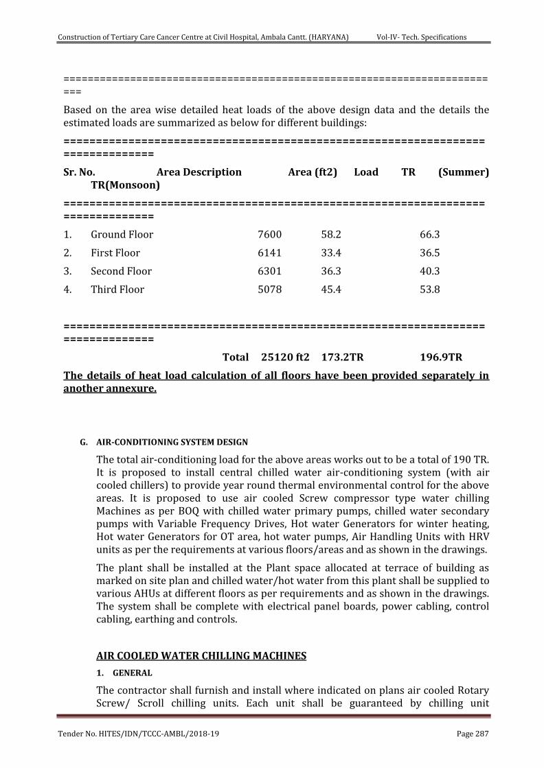
Construction of Tertiary Care Cancer Centre at Civil Hospital, Ambala Cantt. (HARYANA) Vol-IV- Tech. Specifications
Tender No. HITES/IDN/TCCC-AMBL/2018-19 Page 287
=========================================================================
Based on the area wise detailed heat loads of the above design data and the details the estimated loads are summarized as below for different buildings:
===============================================================================
Sr. No. Area Description Area (ft2) Load TR (Summer) TR(Monsoon)
===============================================================================
1. Ground Floor 7600 58.2 66.3
2. First Floor 6141 33.4 36.5
3. Second Floor 6301 36.3 40.3
4. Third Floor 5078 45.4 53.8
===============================================================================
Total 25120 ft2 173.2TR 196.9TR
The details of heat load calculation of all floors have been provided separately in another annexure.
G. AIR-CONDITIONING SYSTEM DESIGN
The total air-conditioning load for the above areas works out to be a total of 190 TR. It is proposed to install central chilled water air-conditioning system (with air cooled chillers) to provide year round thermal environmental control for the above areas. It is proposed to use air cooled Screw compressor type water chilling Machines as per BOQ with chilled water primary pumps, chilled water secondary pumps with Variable Frequency Drives, Hot water Generators for winter heating, Hot water Generators for OT area, hot water pumps, Air Handling Units with HRV units as per the requirements at various floors/areas and as shown in the drawings.
The plant shall be installed at the Plant space allocated at terrace of building as marked on site plan and chilled water/hot water from this plant shall be supplied to various AHUs at different floors as per requirements and as shown in the drawings. The system shall be complete with electrical panel boards, power cabling, control cabling, earthing and controls.
AIR COOLED WATER CHILLING MACHINES
1. GENERAL
The contractor shall furnish and install where indicated on plans air cooled Rotary Screw/ Scroll chilling units. Each unit shall be guaranteed by chilling unit
Construction of Tertiary Care Cancer Centre at Civil Hospital, Ambala Cantt. (HARYANA) Vol-IV- Tech. Specifications
Tender No. HITES/IDN/TCCC-AMBL/2018-19 Page 288
manufacturer to produce a capacity of not less than specified tons of refrigeration at specified leaving water temperature with the temperature of ambient air entering the condenser not exceeding 113 degree F (45degree C). The construction and rating of the chillers shall be in accordance with latest AHRI standard 550/590 and shall comply with ANSI B 9.1 safety code, National Electrical code and ASME code. Necessary 3 ph.50 Hz, 220/415 volts, A.C. Power supply shall be made available for all units.
1. CODES & STANDARDS
ASHRAE 15 Safety code for Mechanical refrigeration
ASHRAE 23 Methods of testing and rating positive displacement refrigerant compressors and condensing units
ASHRAE 30 Methods of testing liquid chilling packages ASME SEC VIII DIVI Boiler and pressure vessel code ANSI B 31.5 Code for refrigeration piping
AHRI 550/590 (2003) Standard for Air Cooled Screw chilling packages
AHRI 575 Standard for method of measuring machinery sound within an Equipments space
ISO 1940 Mechanical vibration – Balance quality requirements of rigid rotors
ISO 10816-1 Mechanical vibration – Evaluation of machine vibration of measurements on non-rotating parts. General guidelines
TEMA – C/R Heat Exchanger with acceptable deviation
ASTM: C591 Specification for Polyurethane/ Polyisocyanurate Foam
2. BASIC UNIT
Each unit shall consist in general of multiple semi hermetic screw compressors, air cooled condenser coils, DX/flooded type chiller, condenser fans, outer weather proof casing, automatic control panel and accessories.
3. COMPRESSOR (SCREW TYPE)
Each unit shall have multiple rotary, double bolted hermetic screw compressor
The rotary screw shall be manufactured from forged steel with precision cast male and female profiles which are asymmetrical. The profile of screws shall permit safe operation up to a speed of 3000 RPM for 50 Hz operation. The compressor shall unload from fully loaded to the minimum capacity by means of hydraulically actuated slide valve positioned over both the male and female rotors.
The compressor housing shall be of high grade cast iron, machined with precision, to provide a very close tolerance between the rotors and the housing.
The rotors shall be mounted on antifriction bearings designed to reduce friction and power input. There shall be multiple cylindrical bearings to handle the radial and axial loads.
There shall be built in oil reservoir to ensure full supply of lubricants to all bearings and a check valve to prevent back spin during shut down.
There shall be oil pump or other means of differential pressure inside the compressor for forced lubrication of all parts during startup, running and coasting for shut down. An oil sump header shall be provided in the casing.
Construction of Tertiary Care Cancer Centre at Civil Hospital, Ambala Cantt. (HARYANA) Vol-IV- Tech. Specifications
Tender No. HITES/IDN/TCCC-AMBL/2018-19 Page 289
The units shall be complete with automatic capacity control mechanism, by use of slide value to permit modulation between 20% to 100% of capacity range.
4. COMPRESSOR MOTOR
The driving motor shall be Hermetic squirrel cage type protected against damage by means of built in protection devices.
5. VARIABLE SPEED DRIVE
A variable speed drive shall be factory installed on the chiller and exactly same as per global catalogue. It shall vary the compressor motor speed by controlling the frequency and voltage of the electrical power to the motor. The adaptive capacity control logic shall automatically adjust motor speed and compressor pre-rotation vane position independently for maximum part-load efficiency by analyzing information fed to it by sensors located throughout the chiller.
Drive shall be PWM type utilizing IGBT's with a power factor of 0.95 or better at all loads and speeds. It must also employ harmonic filters to minimize current and voltage distortions.
The variable speed drive shall be unit mounted in a NEMA-1 enclosure with all power and control wiring between the drive and chiller factory installed, including power to the chiller oil pump. Field power wiring shall be a single point connection and electrical lugs for incoming power wiring shall be provided. The entire chiller package shall be UL listed.
The following features shall be provided : a door interlocked circuit breaker, capable of being padlocked; UL listed ground fault protection; over voltage and under voltage protection; 3 phase sensing motor over current protection; single phase protection; insensitive to phase rotation; over temperature protection; digital readout at the chiller unit control panel of:
• Output frequency
• Output voltage
• phase output current
• Input kilowatts (KW) and Kilowatt-hours (KWH)
• Self-diagnostic service parameters
6. DRIVE :
The compressor shall be driven directly or through speed increasing gears as required. The gears and pinions shall be pressure lubricated. The gears shall be provided with oil filter and submerged oil pump. The gears should be of helical type with crown teeth designed such that more than one tooth is in contact at all times to provide even distribution of compressor load and quiet operation. Gears should be integrally assembled in the compressor rotor support and be film lubricated. Each gear should be individually mounted in its own journal and thrust bearings to isolate it from impeller and motor shafts.
Construction of Tertiary Care Cancer Centre at Civil Hospital, Ambala Cantt. (HARYANA) Vol-IV- Tech. Specifications
Tender No. HITES/IDN/TCCC-AMBL/2018-19 Page 290
7. CONDENSER
Condenser coil
The condenser coils shall be made of seamless copper tubes, integrally grooved type arranged in staggered rows and are mechanically expanded into super slit aluminum fins (the coil shall be circuited for sub cooling. The coil shall be minimum three rows deep with atleast 12 fins per inch) or micro channel type, parallel flow aluminum alloy tubes metallurgically brazed as one piece to enhance aluminum fins. Condenser coil shall be post coated with an electro-deposited and baked flexible epoxy coating (E coat) i.e. finished with polyurethane UV resistant top coat suitable for highly corrosive applications.
Condenser fans
The units shall be furnished with necessary number of direct driven propeller type fans arranged for horizontal or vertical discharge. Condenser fan motor shall have class ‘B’ motor insulation, inherent protection device and shall be permanently lubricated type with resilient mounting. Each fan shall have a safety guard and shall have a low noise level.
8. COOLER
The cooler shall be direct expansion shell and tube type, with steel shell and seamless copper tubes. The refrigerant head shall be removable type. The tubes shall be supported in the shell by adequate stiff supports to eliminate vibrations and noise. The tube ends shall be fixed firmly into the tube sheets to prevent leakage of refrigerant gas.
The cooler shall be tested and stamped against leaks in accordance with ASME code for the refrigerant being used and otherwise tested and constructed in accordance with ASME or equivalent approved code requirements.
The cooler shall have a minimum of 2 independent direct expansion refrigerant circuits.
The cooler shall be factory insulated with 19 mm thick closed cell polyvinyl chloride and further protected by means of heater cables.
9. CONTROLS
All the controls shall be factory wired and located in a weather proof enclosure. These shall include fuses, selector switch, oil safety switch, high and low pressure cutouts, interlocks for crankcase heaters and inherent motor protection devices, fan control thermostat, recycling pump-down circuit, high discharge temperature cutout indicator lamps shall be provided for the compressor units.
Necessary starters for compressor motors and condenser fan motors shall be included and provided within the unit. The compressor & the condenser fans shall be electrically interlocked such that the compressor can run only when at least one of the condenser fans are running.
Air Chilling Machine Control System
The Air chilling unit shall be complete with microprocessor based type control system, which shall have the following features:-
Construction of Tertiary Care Cancer Centre at Civil Hospital, Ambala Cantt. (HARYANA) Vol-IV- Tech. Specifications
Tender No. HITES/IDN/TCCC-AMBL/2018-19 Page 291
Electric expansion valve for economic operation of the system
Self-diagnostic capability to locate faults and give early warning.
Leaving chilled water temperature control and reset capability, with provision to accept over ride commands from a central BMS system.
Automatic sequencing of various functions for starting, running and stopping of the various components of the unit based on demand.
A programmable microprocessor complete with key pad and LED display window to perform the above functions.
The control package shall also consist of, but not limited to, the following components:
Low control voltage to unit.
Field power and control circuit terminal blocks.
ON/OFF switch.
Replaceable relay board.
Leaving chilled water set point board.
Diagnostic digital display module.
Microprocessor board. Temperature reset board.
The control system shall have an extended module for control and monitoring from a central BMS including the reset of chilled water temperature, ON/OFF / Fault etc.
10. REFRIGERANT CIRCUIT
The refrigerant piping between compressors, chiller and condenser shall be of heavy gauge copper with brazed joints. The circuit shall include sight glass, moisture indicator, solenoid valves, electronic expansion valves, filter driers and necessary shut off valves with charging connections.
11. UNIT CASING
All the above components shall be housed in an outer casing fabricated from galvanized steel, zinc phosphate with multiple coats of baked enamel paint to make the whole casing weather proof for outdoor installation. Removable panels shall be provided for access to all working parts.
The chilling unit shall be AHRI certified as per AHRI 550 / 590. All suppliers shall furnish computer printouts along with their technical bids, giving details of capacity output at design conditions as given in tender.
Chillers shall be Eurovent/AHRI Certified as per BOQ Provisions.
12. MISCELLANEOUS
Each system shall be provided with the following:-
Necessary charge of refrigerant gas and lubricating oil.
Spring vibration isolators below the unit rated by the isolator manufacturers to absorb 90% of unit vibration and as approved by the engineer.
Construction of Tertiary Care Cancer Centre at Civil Hospital, Ambala Cantt. (HARYANA) Vol-IV- Tech. Specifications
Tender No. HITES/IDN/TCCC-AMBL/2018-19 Page 292
Dial type thermometers and pressure gauges for the inlet and outlet of the chilled water lines. (Priced Separately).
Flexible connectors between chilled water lines and cooler inlet and outlet.
Water flow switch at the outlet of chilling unit (Priced separately).
Butterfly valve at the outlet and balancing valve at the inlet of the chillers (Priced separately).
13. Fouling Factor:-
The fouling factor for the cooler shall be not more than value as specified in BOQ.
14. GRAPHIC CONTROL CENTER
The chiller shall be controlled by a unit mounted microprocessor based control center. The chiller control panel shall provide control of chiller operation and monitoring of chiller sensors, actuators, relays and switches.
The control panel shall include a color liquid crystal display (LCD) with touch screen control or surrounded by “soft “keys. The screen shall detail all operations and parameters, using a graphical representation of the chiller and its major components. Panel verbiage shall be available in other languages as an option with English always available. Data shall be displayed in either English or Metric units.
The sophisticated program and sensor shall monitor the chiller water temperature to prevent freeze up. When needed hot gas bypass is available as an option. The panel shall display countdown timer messages so the operator knows when functions are starting and stopping. Every programmable point shall have a pop-up screen with the allowable ranges, so that the chiller cannot be programmed to operate outside of its design limits.
The chiller control panel shall also provide:
1. System operating information including:
a. return and leaving chilled water temperature
b. return and leaving condenser water temperature
c. evaporator and condenser saturation temperature
d. differential oil pressure
e. percent motor current
f. evaporator and condenser saturation temperature
g. compressor discharge temperature
h. oil reservoir temperature
i. oil temperature
j. operating hours
k. number of compressor starts
2. Digital programming of set points through the universal keypad including:
a. leaving chilled water temperature
b. percent current limit
Construction of Tertiary Care Cancer Centre at Civil Hospital, Ambala Cantt. (HARYANA) Vol-IV- Tech. Specifications
Tender No. HITES/IDN/TCCC-AMBL/2018-19 Page 293
c. pull-down demand limiting
d.six-week schedule for starting and stopping the chiller, pumps and tower
e. remote reset temperature range
3. Status messages indicating:
a. system ready to start
b. system running
c. system shutdown
d. system safety shutdown-manual restart
e. system cycling shutdown-auto restart
f. system prelube
g. start inhibit
4. The text displayed within the system status and system details field shall be displayed as a color coded message to indicate severity.
5. Safety shutdowns enunciated through the display and the status bar, and consist of system status, system details, day, time, cause of shutdown, and type of restart required. Safety shutdowns with a fixed speed drive shall include:
a. evaporator – low pressure
b. evaporator – transducer or leaving liquid probe
c. evaporator – transducer or temperature sensor
d. condenser – high pressure contacts open
e. condenser – high pressure
f. condenser – pressure transducer out of range
g. auxiliary safety – contacts closed
h. discharge – high temperature
i. discharge – low temperature
j. oil – high temperature
k. oil – low differential pressure
l. oil – high differential pressure
m. oil – sump pressure transducer out of range
n. oil – differential pressure calibration
o. oil – variable speed pump – pressure setpoint not achieved
p. control panel – power failure
q. motor or starter – current imbalance
r. thrust bearing – proximity probe clearance
s. thrust bearing - proximity probe out – of – range
Construction of Tertiary Care Cancer Centre at Civil Hospital, Ambala Cantt. (HARYANA) Vol-IV- Tech. Specifications
Tender No. HITES/IDN/TCCC-AMBL/2018-19 Page 294
t. thrust bearing – high oil temperature
u. thrust bearing – oil temperature sensor
v. software reboot
5.1 Safety shutdowns with a VSD Shall include:
a. VSD shutdown – requesting fault data
b. VSD – stop contacts open
c. VSD – 110% motor current overload
d. VSD – high phase A, B,C inverter heatsink temp.
e. VSD – high converter heatsink temperature
6. Cycling shutdowns enunciated through the display and the status bar, and consists of system status, system details, day, time, cause of shutdown, and type of restart required. Cycling shutdowns with a fixed speed drive shall include:
a. multiunit cycling – contacts open
b. system cycling - contacts open
c. oil - low temperature differential
d. oil – low temperature
e. control panel - power failure
f. leaving chilled liquid - low temperature
g. leaving chilled liquid - flow switch open
h. motor controller – contacts open
i. motor controller – loss of current
j. power fault
k. control panel - schedule
l. starter – low supply line voltage
m. starter – low supply line voltage
n. proximity probe – low supply voltage
o. oil - variable speed pump - drive contacts open
6.1 Cycling shutdowns with a VSD shall include all necessary parameters.
7. Security access to prevent unauthorized change of set points, to allow local or remote control of the chiller, and to allow manual operation of the prerotation vanes and oil pump. Access shall be through ID and password recognition, which is defined by three different levels of user competence: view, operator, and service.
8. Trending data with the ability to customize points of once every second to once every hour. The panel shall trend different parameters from a list of over 140, without the need of an external monitoring system.
Construction of Tertiary Care Cancer Centre at Civil Hospital, Ambala Cantt. (HARYANA) Vol-IV- Tech. Specifications
Tender No. HITES/IDN/TCCC-AMBL/2018-19 Page 295
9. The operating program stored in non-volatile memory (EPROM) to eliminate reprogramming the chiller due to AC power failure or battery discharge. Programmed setpoints shall be retained in lithium battery-backed RTC memory for a minimum of 10 years with power removed from the system.
10. A fused connection through a transformer in the compressor motor starter to provide individual over- current protected power for all controls.
11. A numbered terminal strip for all required field interlock wiring.
12. An RS-232/RS 485 communication port to output all system operating data, shutdown / cycling message, and a record of the last 10 cycling or safety shutdowns to a field-supplied printer. Data logs to a printer at a set programmable interval. This data can be preprogrammed to print for desired time interval.
13. The capability to interface with a building automation system to provide:
a. remote chiller start and stop
b. remote leaving chiller liquid temperature adjust
c. remote current limit setpoint adjust
d. remote ready to start contacts
e. safety shutdown contacts
f. cycling shutdown contacts
g. run contacts
14 Tests at Factory:
At least one chiller shall be tested on ARI/Eurovent certified test bed at 100%, 75%, 50% and 25% load at AHRI/Eurovent/Design Conditions (to be decided by E-I-C at appropriate stage) to establish IPLV/NPLV at the manufacturer’s works and shall be witnessed by client’s representatives at factory. Nothing extra shall be paid in this regard.
The scope of work of Contractor shall include suitable capacity of chillers with VFDs as specified in BOQ & as per meeting functional requirements complete with R - 134 A refrigerant or as per BOQ (ozone friendly, HFC), open / semi hermatic / hermatically sealed single /multiple Screw compressors complete with single/twin refrigerant circuit, driven by suitable KW Squirrel Cage induction motor complete with water cooled shell & tube condenser, insulated shell and tube flooded chiller, with S.S braided pipe flexible connector, insulation to be mechanically protected similar to chilled water piping insulation, flanged end for chiller & condenser, electronic auto setting water flow switches at condenser & chiller outlet, factory done refrigerant piping, refrigerant and oil first charged, microprocessor based control panel with non-volatile memory & touch screen display, motor driven by chiller / floor mounted air cooled VSD/VFD with IP 54 (or more) enclosure with active harmonic filters with THDI less than 40% or nearest possible as per OEM & accessories, stainless steel braided pipe flexible connector for chiller and condenser at inlet & oulet, IP 44 enclosure for control and terminal box, factory installed electrical
Construction of Tertiary Care Cancer Centre at Civil Hospital, Ambala Cantt. (HARYANA) Vol-IV- Tech. Specifications
Tender No. HITES/IDN/TCCC-AMBL/2018-19 Page 296
disconnect / isolator switch integrating main fuses etc. all mounted on M.S. frame. Motor shall be suitable for 415 volts ± 10%, 50Hz ± 5 %, three phase A.C. supply.
It should include flow switch/DP switch at chiller and condenser, vibration isolators, including oil separators, pressure relief devices, filter drier moisture indicators, refrigerant economizer, integral refrigerant piping and wiring, accessories as required and called for, automatic and safety controls mounted in central console panel.
VIII. IEEE519, 1992 recommendations shall be used for the basis of calculation of total active harmonic distortion (THD) at the point of common coupling (PCC) for VFDs.
Suitable PCC/RCC foundation ( PCC foundation in PCC (1:2:4) type B-1 using 20 mm graded stone aggregate 30 cm above floor level including making connection of inlet & outlet with fittings including nut, bolts, packing etc.) with plaster to be provided.
VACUUM DEGASSER, AIR & DIRT SEPARATOR & DIRT SEPARATOR
VACUUM DEGASSER
The vacuum degasser shall be of a solid and a robust construction. The Vacuum degasser shall work on the Principle of pressure differential dearation. Vacuum degasser shall be installed in a by pass line to CHW header. It shall be able to degas a minimum of 1CMH or 1000 l/h of water at system working pressure.
The degasser shall be capable of refilling the CHW pipeline with degassed water to compensate the volume of vented gases, unit shall be selected as per system's highest working pressure with following features
• Fully automated degassing and water make-up • The Deagasser shall be able to switch itself off when the pipeline achieves
desired Pressure & degassed levels of water. Works on pressure differential deaeration principle
• Built in flow meter to measure degassed and make-up water volumes • Microprocessor based control panel • BMS compatible • All Components, i.e. pump, vacuum tube, valves, interconnecting piping and
control panel mounted on a compact steel frame, It should be with a Multi-stage Centrifugal pump The Degasser shall be of Plug & play type & shall be of automatic operation. Vacuum degasser shall consist of
Vacuum tube with high capacity automatic airvent with an ingress preventer.
Multistage centrifugal pump.
Make-up water and system inlet water connections with motorised valves.
Water outlet connection with motorised valve to enable degasser operation
even at low system pressure.
(Manual preset flow control valves at inlet and outlet are not acceptable.)
Pressure transmitter to regulate pressure / vacuum in the vacuum tube
Construction of Tertiary Care Cancer Centre at Civil Hospital, Ambala Cantt. (HARYANA) Vol-IV- Tech. Specifications
Tender No. HITES/IDN/TCCC-AMBL/2018-19 Page 297
Built in flow meter to measure degassed and make-up water volumes.
Microprocessor based, BMS compatible, control panel with IP54 protection.
All Components, i.e. pump, vacuum tube, valves, interconnecting piping and
control panel mounted on a compact steel frame.
DIRT SEPARATOR
The Dirt separator shall be of a solid and robust construction (Mild Steel). It shall be able to remove solid particles upto 5 microns from water at Velocity between 2-3m/s. All connections, fittings and heads shall be of carbon steel. The medium used to de-aerate and remove dirt shall be manufactured of Steel Tube & a mesh made of copper wire. This medium should be non clogging in nature. The flow should not be obstructed by the dirt collected. A Drain valve should be present at the bottom to remove the accumulated dirt without the need of shutting down the operation of the system. The Dirt Separator shall be insulated depending upon its location (outdoor or indoor). The pressure drop on account of the dirt separator shall not exceed 21 kPa at maximum flow of the chilled water system.
AIR & DIRT SEPARATOR
The Air and Dirt separator shall be of a solid and robust construction (Mild Steel). It shall be able to remove free air and microbubbles as well as remove solid particles upto 5 microns from water at Velocity between 2-3m/s. Removal of Air & dirt shall be through coalescence. The unit shall be able to condition the water to make it highly absorptive at all points in the system .This ensures that microbubbles can no longer exist at any point in the system. All connections, fittings and heads shall be of carbon steel. The medium used to de-aerate and remove dirt shall be manufactured of Steel Tube & a mesh made of copper wire. This medium should be non clogging in nature. An automatic air vent of at least 100mm free area to be connected at the top for the release of the air separated from the water. The flow should not be obstructed by the dirt collected. A Drain valve should be present at the bottom to remove the accumulated dirt without the need of shutting down the operation of the system. The Air & Dirt Separator shall be insulated depending upon its location (outdoor or indoor). The pressure drop on account of the air and dirt separator shall not exceed 21 kPa at maximum flow of the chilled water system
AIR HANDLING UNITS
1 SCOPE
The Scope of this section comprises the supply, erection, testing and commissioning of double skin Air Handling Units conforming to these Specifications and in accordance with requirements of drawings and schedule of quantities.
2 TYPE
The Air Handling Units shall be of floor mounted draw through type having sections such as filter section with pre-filters, microvee filters and HEPA filters as required under BOQ ,cooling coil section with suitable chilled water cooling coil, fan section with DIDW fan, mixing section where required under BOQ. Humidification section with centrifugal fan as per schedule of quantities and arrangement shown on the drawings.
Construction of Tertiary Care Cancer Centre at Civil Hospital, Ambala Cantt. (HARYANA) Vol-IV- Tech. Specifications
Tender No. HITES/IDN/TCCC-AMBL/2018-19 Page 298
3 CAPACITY
The air moving and coil capacities (Air Conditioning Load), maximum motor HP, static pressure shall be as shown in Schedule of equipment and quantities and on drawings.
4 CASING
The housing/ casing of the air handling unit shall be of double skin construction. The housing shall be so made that it can be delivered at site in total/ semi knock down conditions depending upon the conditions. The frame work shall be of extruded aluminum hollow sections with thermal break profile fitted with pre-formed insulated sections. All the members shall be assembled thru mechanical joints to make a sturdy and strong frame work for various sections. Casings should be as per EN 1886.
Double skin panels (each not exceeding 750mm wide) shall be made of 22G pre-coated Galvanized sheet steel and 22G galvanized sheet inside with pressure injected PU foam insulation of 25mm thick X 38 Kg/Cu.M in in between, these panels shall be with thermal break barrier also. The panels shall be bolted from inside on to the frame work with soft rubber gasket in between to make the joints air tight.
Frame work for each section shall be bolted together with soft rubber gasket in between to make the joints air tight. Suitable doors with powder coated hinges and latches shall be provided for access to various panels for maintenance.
The fan and the motor arrangement shall be mounted on to the extruded aluminium frame work. The entire housing i.e. The Air Handling Unit shall be mounted on extruded aluminium base channel framework.
Drain pan shall be constructed of 16 SS sheet having 12 mm thick 32 Kq/Cu. XPE insulation. The pan shall have necessary slope to facilitate for fast removal of condensate.
The drain pan shall be of 18 G stainless steel (SS-304 grade) with necessary slope to facilitate fast removal of condensate. Necessary arrangement will be provided to slide the coil in the drain pan. The drain pan shall be insulated with 19 mm thick close cell Nitrile insulation (self-adhesive)/as per manufacturer’s specifications or equivalent
5 MOTOR AND DRIVE
Fan motors shall be 230 ± 10% volts 50 cycles 3 phase totally enclosed fan cooled with IP-55 rotation, having efficiency class IE-3, suitable for 415 Volts, 50 Hz AC supply. Motor shall be especially designed for quite operation and motor speed shall not exceed 1440 RPM. Drive to fan shall be provided through belt drive arrangement. Belts shall be of oil-resistant type. Adjustable sheaves shall be provided.
6 FAN
The fan shall be backward, curved double inlet double width type complete with motor and drive package. The wheel and housing shall be fabricated from heavy gauge galvanized steel. The fan impeller shall be mounted on a solid shaft supported to housing with angle iron frame and pillow block heavy duty ball bearings. The fan shall be selected for a speed not exceeding 1000 RPM. The fan outlet velocity shall not be more than 1800 rpm. Fan housing with motor shall be mounted on a common steel base mounted inside the AHU on anti-vibration springs or cushy foot mount.
Construction of Tertiary Care Cancer Centre at Civil Hospital, Ambala Cantt. (HARYANA) Vol-IV- Tech. Specifications
Tender No. HITES/IDN/TCCC-AMBL/2018-19 Page 299
The fan shall be direct driven type. Another fire retardant canvass connection shall be provide at unit outlet to connect the ducts.
7. Cooling Coils:
The cooling coil shall be seamless copper tubes not less than 0.437 mm thick and 12.5 mm O.D. The coil shall have continuous aluminum fins. The tube shall be staggered in the direction of air flow. The fins shall be uniformly bonded to the tubes by mechanical expansion of the tube. The coil shall be tested against leaks
At a hydraulic pressure of 21kg/m3 for a period of two hours. The water headers shall be of copper pipes to connect all the tubes. The header shall be complete with water In/Out connections, vent plug and drain at the bottom and designed to provide a water velocity between 0.6 to 1.8 m/s ( 2 to 6 FPS)
8. Filters :
As asked for under Bill of quantities.
9. Electrical Panel :
Each unit shall have its own electric panel consisting of MCCB / fuse switch unit, starter, indicating lamps, incoming/outgoing internal and external wiring and earthing as per the details in BOQ.
10 Fresh Air Control :
An adjustable damper of GI sheet along with bird screen ,air inlet louvers and air filters shall be provided for fresh air entry. The damper shall be sized for 50% of designed air quantity.
11 Limitations :
The air velocity across the cooling coils shall not exceed 500 fpm.
The fan outlet velocity shall not exceed 1800 fps (9m/s) in any case.
The velocity across the filters shall not exceed 500 fpm in any case.
12 TESTING
Cooling/Heating capacity of various air-handling unit models shall be computed from the measurements of airflow and dry and wet bulb temperatures of air entering and leaving the coil.
Flow measurements shall be by anemometer and temperature measurements by accurately calibrated mercury in glass thermometer. Computed result shall conform to the specified capacities and quoted ratings. Consumption shall be computed from measurements of incoming voltage and input current.
13 DATA / INFORMATION:-
The contractor shall complete the Data Sheet & submit as a part of his technical submittal at appropriate stage.
HEAT RECOVERY VENTILLATION SECTION: (ENTHALPY WHEEL)
a. Wheel: The wheel shall be made of alternate layer of corrugated and intervening flat composite material of aluminium foil of uniform width to ensure smooth surface. The cross contamination between the two stream shall be nil and leakage less than
Construction of Tertiary Care Cancer Centre at Civil Hospital, Ambala Cantt. (HARYANA) Vol-IV- Tech. Specifications
Tender No. HITES/IDN/TCCC-AMBL/2018-19 Page 300
0.04%. The wheel medium should be bonded together to form rigid transfer medium forming a multitude of narrow channels ensuring laminar flow. The wheels shall be of proven design.
The wheel can be fully wound or on larger units, sectorised, i.e. assembled in segments. In latter case the segments are assembled between rigid spokes thus ensuring structural longevity and allowing replacement of one or specific segments only.
The wheel shall be cleanable by spraying its face surface with compressed air, low temperature steam or hot water or by vacuum cleaning without affecting its latent properties.
The face velocity across the wheel should not exceed 700 fpm (3.5 m/s).
The wheels shall be tested in accordance with AHRI (Std. 1060) or ASHRAE S4-78 method of testing air to air heat exchangers. Development an manufacturers shall meet all quality assurance criteria specified in BSEN ISO 9001.
The minimum sensible and latent efficiencies should be 75%. A computerized selection should be enclosed along with offer.
b. Casing: The casing shall be constructed as a single skin, self-supporting, galvanized sheet steel structure and include rotary wheel support beams and purging sector. The casing shall be supplied with access panels to facilitate inspection and service. Size 2150 mm and larger shall be in two sections to facilitate shipping and handling.
c. Seals: The casing shall be equipped with adjustable brush seals, which minimize the carryover to max 0.05 – 0.2%.
d. Hub and Spokes: Hub and Spokes on one piece rotor shall be Aluminium and on sectorrized rotor Hub shall be made of steel, painted with ani corosion paint and galvanized sheet steel spokes.
e. Drive: The wheel shall be belt driven along its perimeter. A constant speed fractional horsepower motor shall be used. The motor shall be mounted on a self-adjusting base to provide correct belt tension.
TESTING
The Thermal Wheel shall be tested in accordance with the parameters fixed as below.
Supply Air Capacity - FDB/FWB.
Exhaust Air Capacity - FDB / FWB.
Fresh Air Capacity - FDB / FWB
Heat exchanger units(HRV) in double skin construction,constructed out of extruded Aluminium section frame with puf insulated panels,blowers,IE-3 Motor plate to plate type Aluminium heat exchanger and filters.The unit will have two separate passages one for supply of fresh air and the other for exhaust of cool air from the rooms after the revovery of energy. Efficiency of these heat exchangers shall be 60-65%.The plate to plate heat exchanger shall be rigid thermally bonded seamless Aluminium channels separated by extruded aluminium spacers of the following capacity.
Construction of Tertiary Care Cancer Centre at Civil Hospital, Ambala Cantt. (HARYANA) Vol-IV- Tech. Specifications
Tender No. HITES/IDN/TCCC-AMBL/2018-19 Page 301
VARIABLE FREQUENCY DRIVES FOR HVAC SYSTEMS
1. GENERAL REQUIREMENTS
a. This specification covers complete variable frequency drives (VFDs) designated on the drawing schedules to be variable speed. All standard and optional features shall be included within the VFD.
b. The frequency converter shall not be a general purpose product, but a dedicated HVAC engineered product.
c. The VFD and its options shall be factory mounted and tested as a single unit under full load before dispatch.
d. The VFD shall be tested to UL 508C. The appropriate UL label shall be applied.
e. The VFD shall be CE marked and conform to the European Union Electro Magnetic Compatibility directive.
f. The VFD shall be UL listed for a short circuit current rating of 100 kA and labeled with this rating.
2. TECHNICAL REQUIREMENTS
2.1 The VFD shall convert incoming fixed frequency three-phase AC power into an
adjustable frequency and voltage for controlling the speed of three-phase AC
motors. The motor current shall closely approximate a sine wave. Motor voltage
shall be varied with frequency to maintain desired motor magnetization current
suitable for the driven load and to eliminate the need for motor derating.
When properly sized, the VFD shall allow the motor to produce full rated power at rated motor voltage, current, and speed without using the motor's service factor. VFDs utilizing sine weighted/coded modulation (with or without 3rd harmonic injection) must provide data verifying that the motors will not draw more than full load current during full load and full speed operation.
2.2 The VFD shall include an input full-wave bridge rectifier and maintain a
fundamental (displacement) power factor near unity regardless of speed or load.
2.3 The VFD shall have a dual 5% impedance DC link reactor (harmonic filters) on the
positive and negative rails of the DC bus to minimize power line harmonics and
protect the VFD from power line transients. The chokes shall be non-saturating.
Swinging chokes that do not provide full harmonic filtering throughout the entire
load range are not acceptable.
2.4 VFDs with saturating (non-linear) DC link reactors shall require an additional 3%
AC line reactor to provide acceptable harmonic performance at full load, where
harmonic performance is most critical.
IEEE519, 1992 recommendations shall be used for the basis of calculation of total harmonic distortion (THD) at the point of common coupling (PCC). On request VFD manufacturer shall provide THD figures for the total connected load. The contractor shall provide details of supply transformer rating, impedance, short circuit current, short circuit impedance etc to allow this calculation to be made.
Construction of Tertiary Care Cancer Centre at Civil Hospital, Ambala Cantt. (HARYANA) Vol-IV- Tech. Specifications
Tender No. HITES/IDN/TCCC-AMBL/2018-19 Page 302
2.5 All VFDs shall contain integral EMC Filters to attenuate Radio Frequency
Interference conducted to the AC power line. The VFDs shall comply with the
emission and immunity requirements of IEC 61800-3 : 2004, Category C1 with
50m motor cable (unrestricted distribution). The suppliers of VFDs shall include
additional EMC filters if required to meet compliance to this requirement.
2.6 The VFD’s full load output current rating shall meet or exceed the normal rated
currents of standard IEC induction motors. The VFD shall be able to provide full
rated output current continuously, 110% of rated current for 60 seconds and
120% of rated torque for up to 0.5 second while starting.
2.7 The VFD shall provide full motor torque at any selected frequency from 20 Hz to
base speed while providing a variable torque V/Hz output at reduced speed. This
is to allow driving direct drive fans without high speed derating or low speed
excessive magnetization, as would occur if a constant torque V/Hz curve was used
at reduced speeds. Breakaway current of 160% shall be available.
2.8 A programmable automatic energy optimization selection feature shall be provided
as standard in the VFD. This feature shall automatically and continuously monitor
the motor’s speed and load to adjust the applied voltage to maximize energy
savings.
2.9 The VFD must be able to produce full torque at low speed to operate direct driven
fans.
2.10 Output power circuit switching shall be able to be accomplished without interlocks
or damage to the VFD.
2.11 An Automatic Motor Adaptation algorithm shall measure motor stator resistance
and reactance to optimize performance and efficiency. It shall not be necessary to
run the motor or de-couple the motor from the load to perform the test.
2.12 Galvanic isolation shall be provided between the VFD’s power circuitry and control
circuitry to ensure operator safety and to protect connected electronic control
equipment from damage caused by voltage spikes, current surges, and ground loop
currents. VFDs not including either galvanic or optical isolation on both analog I/O
and discrete digital I/O shall include additional isolation modules.
2.13 VFD shall minimize the audible motor noise through the used of an adjustable
carrier frequency. The carrier frequency shall be automatically adjusted to
optimize motor and VFD operation while reducing motor noise. VFDs with fixed
carrier frequency are not acceptable.
2.14 The VFD shall allow up to at least 100 meters of SWA (Single Wire Armour) cable to
be used between the FC and the motor and allow the use of MICS (Mineral
Insulated Copper Sheath) cable in the motor circuit for fire locations.
3. PROTECTIVE FEATURES
Construction of Tertiary Care Cancer Centre at Civil Hospital, Ambala Cantt. (HARYANA) Vol-IV- Tech. Specifications
Tender No. HITES/IDN/TCCC-AMBL/2018-19 Page 303
3.1 Overload protection in VFD shall automatically compensate for changes in motor
speed.
3.2 Protection against input transients, loss of AC line phase, output short circuit,
output ground fault, over voltage, under voltage, VFD over temperature and motor
over temperature. The VFD shall display all faults in plain language. Codes are not
acceptable.
3.3 Protect VFD from input phase loss. The VFD should be able to protect itself from
damage and indicate the phase loss condition. During an input phase loss
condition, the VFD shall be able to be programmed to either trip off while
displaying an alarm, issue a warning while running at reduced output capacity, or
issue a warning while running at full commanded speed. This function is
independent of which input power phase is lost.
3.4 Protect from under voltage. The VFD shall provide full rated output with an input
voltage as low as 90% of the nominal. The VFD will continue to operate with
reduced output, without faulting, with an input voltage as low as 70% of the
nominal voltage.
3.5 VFD shall include current sensors on all three output phases to accurately measure
motor current, protect the VFD from output short circuits, output ground faults,
and act as a motor overload. If an output phase loss is detected, the VFD will trip
off and identify which of the output phases is low or lost.
3.6 If the temperature of the VFD’s heat sink rises to 80C, the VFD shall automatically
reduce its carrier frequency to reduce the heat sink temperature. It shall also be
possible to program the VFD so that it reduces its output current limit value if the
VFD’s temperature becomes too high.
3.7 In order to ensure operation during periods of overload, it must be possible to
program the VFD to automatically reduce its output current to a programmed
value during periods of excessive load. This allows the VFD to continue to run the
load without tripping.
3.8 The VFD shall have temperature controlled cooling fan(s) for quiet operation,
minimized losses, and increased fan life. At low loads or low ambient
temperatures, the fan(s) may be off even when the VFD is running.
3.9 Protect from output switching : The VFD shall be fully protected from switching a
contactor / isolator at the output without causing tripping e.g.: for switching
on/off the isolators of the AHU / ventilation fans / pumps near the motor with VFD
in ON mode.
3.10 The VFD shall store in memory the last 10 alarms. A description of the alarm, and
the date and time of the alarm shall be recorded.
3.11 When used with a pumping system, the VFD shall be able to detect no-flow
situations, dry pump conditions, and operation off the end of the pump curve. It
Construction of Tertiary Care Cancer Centre at Civil Hospital, Ambala Cantt. (HARYANA) Vol-IV- Tech. Specifications
Tender No. HITES/IDN/TCCC-AMBL/2018-19 Page 304
shall be programmable to take appropriate protective action when one of the
above situations is detected.
4. INTERFACE FEATURES
4.1 Auto keys shall be provided on the control panel to start and stop the VFD and
determine the source of the speed reference. It shall be possible to either disable
these keys or password protect them from undesired operation.
4.2 There shall be an “Info” key on the keypad. The Info key shall include “on-line”
context sensitive assistance for programming and troubleshooting.
4.3 The VFD shall be programmable to provide a digital output signal to indicate
whether the VFD is in Manual or Auto mode. This is to alert the Building
Automation System whether the VFD is being controlled locally or by the Building
Automation System.
4.4 Password protected keypad with alphanumeric, graphical, backlit display can be
remotely mounted. Two levels of password protection shall be provided to guard
against unauthorized parameter changes.
4.5 All VFDs shall have the same customer interface. The keypad and display shall be
identical and interchangeable for all sizes of VFDs.
4.6 To set up multiple VFDs, it shall be possible to upload all setup parameters to the
VFD’s keypad, place that keypad on all other VFDs in turn and download the setup
parameters to each VFD. To facilitate setting up VFDs of various sizes, it shall be
possible to download from the keypad only size independent parameters. Keypad
shall provide visual indication of copy status.
4.7 Display shall be programmable to communicate in multiple languages including
English, Chinese, Korean, Japanese, Thai and Indonesian.
4.8 A Red FAULT light, a yellow WARNING light and a green POWER-ON light shall be
provided. These indications shall be visible both on the keypad and on the VFD
when the keypad is removed.
4.9 A quick setup menu with factory preset typical HVAC parameters shall be provided
on the VFD. The VFD shall also have individual Fan, Pump, and Compressor menus
specifically designed to facilitate start-up of these applications.
4.10 A three-feedback PID controller to control the speed of the VFD shall be standard.
4.11 This controller shall accept up to three feedback signals. It shall be programmable
to compare the feedback signals to a common set point or to individual set points
and to automatically select either the maximum or minimum deviating signal as
the controlling signal. It shall also be possible to calculate the controlling feedback
signal as the average of all feedback signals or the difference between a pair of
feedback signals.
4.12 The VFD shall be able to apply individual scaling to each feedback signal.
Construction of Tertiary Care Cancer Centre at Civil Hospital, Ambala Cantt. (HARYANA) Vol-IV- Tech. Specifications
Tender No. HITES/IDN/TCCC-AMBL/2018-19 Page 305
4.13 For fan flow tracking applications, the VFD shall be able to calculate the square root
of any or all individual feedback signals so that a pressure sensor can be used to
measure air flow.
4.14 The VFD’s PID controller shall be able to actively adjust its setpoint based on flow.
This allows the VFD to compensate for a pressure feedback sensor which is located
near the output of the pump rather than out in the controlled system.
4.15 The VFD shall have three additional PID controllers which can be used to control
damper and valve positioners in the system and to provide setpoint reset.
4.16 Floating point control interface shall be provided to increase/decrease speed in
response to contact closures.
4.17 Five simultaneous meter displays shall be available. They shall be selectable from
(at a minimum), frequency, motor current, motor voltage, VFD output power, VFD
output energy, VFD temperature in degrees, feedback signals in their own units,
among others.
4.18 Programmable Sleep Mode shall be able to stop the VFD. When its output frequency
drops below set “sleep” level for a specified time, when an external contact
commands that the VFD go into Sleep Mode, or when the VFD detects a no-flow
situation, the VFD may be programmed to stop. When the VFD’s speed is being
controlled by its PID controller, it shall be possible to program a “wake-up”
feedback value that will cause the VFD to start. To avoid excessive starting and
stopping of the driven equipment, it shall be possible to program a minimum run
time before sleep mode can be initiated and a minimum sleep time for the VFD.
4.19 A run permissive circuit shall be provided to accept a “system ready” signal to
ensure that the VFD does not start until dampers or other auxiliary equipment are
in the proper state for VFD operation. The run permissive circuit shall also be
capable of initiating an output “run request” signal to indicate to the external
equipment that the VFD has received a request to run.
4.20 VFD shall be programmable to display feedback signals in appropriate units, such as
inches of water column (in-wg), pressure per square inch (psi) or temperature
(°F). Examples can be room temperature in 0C , return air temperature in 0C ,
supply air temperature in 0C, CO2 concentration in ppm, pressure in bar,
differential pressure in PSI etc.
4.21 VFD shall be programmable to sense the loss of load. The VFD shall be
programmable to signal this condition via a keypad warning, relay output and/or
over the serial communications bus. To ensure against nuisance indications, this
feature must be based on motor torque, not current, and must include a proof
timer to keep brief periods of no load from falsely triggering this indication.
4.22 Standard Control and Monitoring Inputs and Outputs
a. Four dedicated, programmable digital inputs shall be provided for interfacing with the systems control and safety interlock circuitry.
Construction of Tertiary Care Cancer Centre at Civil Hospital, Ambala Cantt. (HARYANA) Vol-IV- Tech. Specifications
Tender No. HITES/IDN/TCCC-AMBL/2018-19 Page 306
b. Two terminals shall be programmable to act as either as digital outputs or additional digital inputs.
c. Two programmable relay outputs, Form C 240 V AC, 2 A, shall be provided for remote indication of VFD status.
d. Each relay shall have an adjustable on delay / off delay time.
e. Two programmable analog inputs shall be provided that can be either direct-or-reverse acting.
f. Each shall be independently selectable to be used with either an analog voltage or current signal.
g. The maximum and minimum range of each shall be able to be independently scalable from 0 to 10 V dc and 0 to 20 mA.
h. A programmable low-pass filter for either or both of the analog inputs must be included to compensate for noise.
i. The VFD shall provide front panel meter displays programmable to show the value of each analog input signal for system set-up and troubleshooting,
j. One programmable analog current output (0/4 to 20 mA) shall be provided for indication of VFD status. This output shall be programmable to show the reference or feedback signal supplied to the VFD and for VFD output frequency, current and power. It shall be possible to scale the minimum and maximum values of this output.
k. It shall be possible to read the status of all analog and digital inputs of the VFD through serial bus communications.
l. It shall be possible to command all digital and analog output through the serial communication bus.
4.23 Optional Control and Monitoring Inputs and Outputs
a. It shall be possible to add optional modules to the VFD in the field to expand its analog and digital inputs and outputs.
b. These modules shall use rigid connectors to plug into the VFD’s control card.
c. The VFD shall automatically recognize the option module after it is powered up. There shall be no need to manually configure the module.
d. Modules may include such items as:
e. Additional digital outputs, including relay outputs
f. Additional digital inputs
g. Additional analog outputs
h. Additional analog inputs, including Ni or Pt temperature sensor inputs
i. It shall be possible through serial bus communications to control the status of all optional analog and digital outputs of the VFD.
4.24 Standard programmable firefighter’s override mode allows a digital input to control
the VFD and override all other local or remote commands. It shall be possible to
program the VFD so that it will ignore most normal VFD safety circuits including
Construction of Tertiary Care Cancer Centre at Civil Hospital, Ambala Cantt. (HARYANA) Vol-IV- Tech. Specifications
Tender No. HITES/IDN/TCCC-AMBL/2018-19 Page 307
motor overload. The VFD shall display FIREMODE whenever in firefighter’s
override mode. Fire mode shall allow selection of forward or reverse operation
and the selection of a speed source or preset speed, as required to accommodate
local fire codes, standards and conditions.
4.25 A real-time clock shall be an integral part of the VFD.
a. It shall be possible to use this to display the current date and time on the VFD’s display.
b. Ten programmable time periods, with individually selectable ON and OFF functions shall be available. The clock shall also be programmable to control start/stop functions, constant speeds, PID parameter setpoints and output relays. Is shall be possible to program unique events that occur only during normal work days, others that occur only on non-work days, and others that occur on specific days or dates. The manufacturer shall provide free PC-based software to set up the calendar for this schedule.
c. All VFD faults shall be time stamped to aid troubleshooting.
d. It shall be possible to program maintenance reminders based on date and time, VFD running hours, or VFD operating hours.
e. The real-time clock shall be able to time and date stamp all faults recorded in the VFD fault log.
f. The VFD shall be able to store load profile data to assist in analyzing the system demand and energy consumption over time.
i. The VFD shall include a sequential logic controller to provide advanced control interface capabilities. This shall include:
ii. Comparators for comparing VFD analog values to programmed trigger values
iii. Logic operators to combine up to three logic expressions using Boolean algebra
iv. Delay timers
v. A 20-step programmable structure
4.26 The VFD shall include a Cascade Controller which allows the VFD to operate in
closed loop set point (PID) control mode for one motor at a controlled speed and
control the operation of 3 additional constant speed motor starters.
5. SERIAL COMMUNICATIONS
1.1 The VFD shall include a standard EIA-485 communications port and capabilities to
be connected to the following serial communication protocols at no additional cost
and without a need to install any additional hardware or software in the VFD:
a. Metasys N2
b. Modbus RTU
1.2 VFD shall have standard USB port for direct connection of Personal Computer (PC)
to the VFD. The manufacturer shall provide at no-charge- PC software to allow
complete setup and access of the VFD and logs of VFD operation through the USB
Construction of Tertiary Care Cancer Centre at Civil Hospital, Ambala Cantt. (HARYANA) Vol-IV- Tech. Specifications
Tender No. HITES/IDN/TCCC-AMBL/2018-19 Page 308
port. It shall be possible to communicate to the VFD through this USB port without
interrupting VFD communications to the building management system.
1.3 The VFD shall have provisions for an optional 24 V DC back-up power interface to
power the VFD’s control card. This is to allow the VFD to continue to communicate
to the building automation system even if power to the VFD is lost.
6. ADJUSTMENTS
6.1 The VFD shall have a manually adjustable carrier frequency that can be adjusted in
0.5 kHz increments to allow the user to select the desired operating
characteristics. The VFD shall also be programmable to automatically reduce its
carrier frequency to avoid tripping due to thermal loading.
6.2 Four independent setups shall be provided.
6.3 Four preset speeds per setup shall be provided for a total of 16.
6.4 Each setup shall have two programmable ramp up and ramp down times.
Acceleration and deceleration ramp times shall be adjustable over the range from
1 to 3,600 seconds.
Each setup shall be programmable for a unique current limit value. If the output current from the VFD reaches this value, any further attempt to increase the current produced by the VFD will cause the VFD to reduce its output frequency to reduce the load on the VFD. If desired, it shall be possible to program a timer which will cause the VFD to trip off after a programmed time period.
If the VFD trips on one of the following conditions, the VFD shall be programmable for automatic or manual reset: external interlock, under-voltage, over-voltage, current limit, over temperature, and VFD overload. The number of restart attempts shall be selectable from 0 through 20 or infinitely and the time between attempts shall be adjustable from 0 through 600 seconds.
An automatic “start delay” may be selected from 0 to 120 seconds. During this delay time, the VFD shall be programmable to either apply no voltage to the motor or apply a DC braking current if desired.
Four programmable critical frequency lockout ranges to prevent the VFD from operating the load at a speed that causes vibration in the driven equipment shall be provided. Semi-automatic setting of lockout ranges shall simplify the set-up.
7. OPTIONAL FEATURES
7.1 All optional features shall be built and mounted by VFD manufacturer as an inbuilt
factory solution. All optional features shall be UL listed by the VFD manufacturer
as a complete assembly and carry a UL label.
8. SERVICE CONDITIONS
8.1 Ambient temperature at full speed, full load operation with continuous drive rated
output current:
a. -10 to 45°C for ratings upto 90 kW without derating
Construction of Tertiary Care Cancer Centre at Civil Hospital, Ambala Cantt. (HARYANA) Vol-IV- Tech. Specifications
Tender No. HITES/IDN/TCCC-AMBL/2018-19 Page 309
b. -10 to 40°C for ratings 110 kW and higher without derating
c. Relative Humidity : 0 to 95%, non-condensing.
d. Elevation : Up to 3,300 feet without derating.
e. AC line voltage variation : + 10% of nominal with full output.
f. VFD Enclosure protection : IP 55, integral, with no additional cabinets.
g. Side Clearances : No side clearance shall be required for cooling.
h. All power and control wiring shall be done from the bottom.
i. All VFDs shall be plenum rated.
9. QUALITY ASSURANCE
9.1. To ensure quality, the complete VFD shall be tested by the manufacturer. The VFD
shall drive a motor connected to a dynamometer at full load and speed and shall be
cycled during the automated test procedure.
9.2. All optional features shall be functionally tested at the factory for proper operation.
FILTERS
1. GENERAL
This section covers the general requirements for special type of filters to be installed in air moving equipment or air ducts.
2. PRE-FILTERS (FABRIC TYPE)
Synthetic fibre Pre-filters shall be in light weight aluminium framed with non woven synthetic fibre replaceable media. The filter shall have an efficiency of 90 percent down to 10 microns particles size when tested as per B.S.2831 standards. The filter frame shall be of aluminium and shall be suitable for mounting in Air handling units or ducts as required at site. The velocity across the face of the filter shall not exceed 500 FPM and the pressure drop across the filter shall not exceed 4mm. The filters shall be suitable for operation under 100 percent relative humidity and 120 deg.C temperature conditions.
3. MICROVEE FILTERS (FINE FILTERS)
Microvee filters shall be of dry type. Filters media shall be made from washable non woven synthetic fibre replaceable media reinforced with HDPE cloth & Aluminum mesh, specially treated with antifungal and bactericidal agents to prevent growth of micro organisms. The filter media shall be treated to permit washing with water several times before discharged. The media shall be properly supported and spaced so that air flow through the filter is uniform. The filter shall be housed in aluminium frame work. Filters shall be designed to remove particle down to 5 micron size and with efficiently of 98.0 percent tested as per BS 2831 using Test Dust II. The filters shall be installed in the air handling units after the chilled water coils. They shall be capable of being replaced or removed for servicing without the use of special tools.
4. HIGH EFFICIENCY PARTICULATE ABSOLUTE (HEPA) FILTERS
Construction of Tertiary Care Cancer Centre at Civil Hospital, Ambala Cantt. (HARYANA) Vol-IV- Tech. Specifications
Tender No. HITES/IDN/TCCC-AMBL/2018-19 Page 310
HEPA filters shall be made in extended surface configuration of deep space folds of sub micron glass fibers. The filter media shall be housed in an aluminium sheet frame provided with double turned flanges and closed cell neoprene gasket. The filter media shall not absorb moisture, stretch, swell or undergo chemical change with moisture. The filter shall be resistant to fungus and bacterial growth. Filters shall be free from pin holes and other leaks.
The housing shall be designed to install the HEPA filters in the terminal locations in the false ceiling or in the duct plenum so that it is removed easily without risking the infiltration of dust whatsoever. The arrangement for filters shall be strictly in accordance with the manufacturers recommendations and shall be approved by the engineer prior to fabrication and installation. The filters shall be protected with aluminium slotted protective grille from the bottom in case of installation of filters in false ceiling air terminals. All MS parts shall be derusted and shall be epoxy painted. The aluminium grilles shall be made from 1.6 mm aluminium sheets with minimum clear area of 60 percent. The grilles shall be anodised stove enamel painted as approved by the Engineer.
5. LAMINAR FLOW HEPA TENT:
i. Introduction :
Diffusers are available for flush mounting in the ceiling. Suitable angle frames are also provided for the modular panel construction. The units are available in three standard sizes for top entry complete with opposed blade dampers.
ii. Description :
LFD laminar flow HEPA TENT are constructed from SS-304, perforated face with approx 50% perforation. The perforated front face is openable hinge type complete with key operated dampers from front.
iii. Features :
Suitable for modular panel assemblies.
Front Faced with opposed blade dampers.
Pivoting type face plate for damper operation from front.
Easy maintenance and cleaning.
iv. Finishesd Standard :
Epoxy Polyester Powder Coated off white/pure white.
Natural anodised.
Mini Pleat HEPA Filters:- These filters shall remove a broad range of airborne contaminants, including fine dust, smoke soot & pollen. These filters shall increase its energy efficiency due to lower pressure drop in comparison to conventional deep pleat HEPA. The filter housing shall be with a very minimal size. The performance of the filters has to be factory scanned prior to the supply .Individual testing under rigid quality control & modern assembly methods has to be used to ensure conformance to specifications.
Class of filters should be confirmed to
Construction of Tertiary Care Cancer Centre at Civil Hospital, Ambala Cantt. (HARYANA) Vol-IV- Tech. Specifications
Tender No. HITES/IDN/TCCC-AMBL/2018-19 Page 311
ASHRAE 52.2 MERV 16-20
EN 1822 E10-H14
Eurovent 4/5 EU 10-EU 14
IEST RP CC 001.3 A,B,C D
These filters has to be with special grade micro glass fiber paper spaced with uniformly positioned hot melt adhesive beads to ensure optimum air-flow. The filter shall be with micro glass pleated media. The frame shall be with extruded aluminium or SS 304 material. It shall be of hi flow box with flange.
The gasket shall be polyethylene food grade. The maximum operating temperature shall be from 100 deg C to 300 deg C and the maximum humidity shall be 100% RH at 0% condensation. The initial pressure drop shall be 20 mm wg at rated air flow capacity and the final pressure drop shall be within 50 mm wg. Efficiency on 0.3 micron shall be 99.997 %. The media shall be epoxy sealed & DOP tested.
ECBC Mandatory Requirements for HVAC Works- It needs to be complied by Contractor.
FAN COIL UNITS
1. SCOPE
This section covers the technical requirements for manufacture, testing at works, and delivering at site, testing after installation, commissioning of fan coil units conforming to these specifications and in accordance with the requirement of the drawings and DBR.
2. TYPE
The fan coil unit shall be horizontal type to be mounted within ceiling space draw through type complete with finned coil, fan with motor (IE-3 efficiency class), double skin insulated drain pan, one or more centrifugal fans and motors, cleanable air filters & fan speed regulator & other controls as described. Horizontal fan coil units shall be provided with auxiliary secondary condensate drain pan.
i. Capacity
The air moving and coil capacities shall be as shown on Drawings and as per requirements.
ii. Cabinets
Cabinets shall be constructed of 18 gauge die-formed cold-rolled galvanized sheet steel, bowdlerized and painted with approved shade of powder coating finish and shall have access doors to piping and controls. Access panels shall have positive locking fasteners for easy removal. Horizontal furred-in type units mounted within ceiling space shall be provided with a cabinet housing, the coil and fan section with provision to mount filters within the fan section.
iii. Interior Chassis
Construction of Tertiary Care Cancer Centre at Civil Hospital, Ambala Cantt. (HARYANA) Vol-IV- Tech. Specifications
Tender No. HITES/IDN/TCCC-AMBL/2018-19 Page 312
The interior chassis shall be constructed of not less than 16 gauge cold rolled galvanized sheet steel bowdlerized and painted with approved shade of powder coating finish. All ceiling suspended fan coil units shall be securely mounted from the building structure with top panel set dead level in both directions. In case of ceiling suspended horizontal units, fan deck and cooling coil shall be easily removable from FCU without lowering down of the FCU or disturbing the other installation.
iv. Fan Section
This shall consist of two lightweight aluminum impellers of forward curved type, both statically and dynamically balanced.
The two impellers shall be directly mounted on to a double shaft, single phase multiple winding motor capable of running at three speeds
A GI plenum shall connect fan outlet to the coil.
v. Cooling Coil
The coil shall be of seamless copper tube of minimum 10 mm OD and wall thickness shall be minimum 0.5 mm. All bends and joints shall be enclosed within insulated end sections of the base unit for protection against sweating. Each coil shall be provided with air vent. All coils shall be factory tested at 21 kg per sq.cm. (300psig) air pressure when submerged in water. Fin spacing shall be 4 to 5 fins per cm. Tubes shall be mechanically/ hydraulically expanded for minimum thermal contact resistance with fins. Air vent shall be provided in headers at a level higher than coils. The cooling coil shall be easily removable from backside of FCU without disturbing the other installations. The copper tube or pipe should not be manufactured from reprocessed or recycled copper
vi. Drain Pans
Primary drain pan shall be of double skin construction fabricated from 22 gauge stainless steel with all corners enclosed. An additional inner bottom panel of 22 G thick stainless steel sheet shall be provided to prevent damage to insulation. The pan shall be insulated with minimum 15mm thick expanded polyethylene insulation sandwiched between top and bottom panels to prevent condensation. The pan shall be of sufficient size to accommodate cooling coil supply and return water header and bends and control valves.
The auxiliary condensate drain pan shall be similar in construction to primary drain pan and size larger than primary drain pan to catch all overflows in case primary drain pan gets choked. Drain from auxiliary drain pan shall be connected to drain from primary drain pan through a tee connection and piped to vertical risers.
vii. Motor
Motor shall be 240 ± 10% volts, 50 Hz, single phase, six poles, rpm not exceeding 1000 at maximum airflow. Motor shall have three speed windings and shall be factory wired to a terminal block mounted within the fan section. Motors shall have extended shaft on both sides. A sturdy switch shall be provided with the unit complete with wiring, for ON/OFF operation & with minimum three speed control of the fan.
viii. AIR FILTER
Construction of Tertiary Care Cancer Centre at Civil Hospital, Ambala Cantt. (HARYANA) Vol-IV- Tech. Specifications
Tender No. HITES/IDN/TCCC-AMBL/2018-19 Page 313
The filter shall be cleanable type 12mm thick AL of MERV 8 rating wire mesh and mounted behind the pan in a filter plenum of GI sheet.
ix. PAINTING
The fan coil units shall be powder coated in approved colour.
3. CONTROLS
All units shall be complete with following controls
i. PIB Control Valve in water lines
ii. Wall mounted thermostat containing three speed and on/off control for fan, speed and
temperature control for summer/ winter air conditioning
iii. 'Y' strainer, ball valve and globe valve as shown on drawings and as per requirements.
4. PERFORMANCE DATA
Fan coil units shall be selected for the lowest operating noise level having standard sound level rating of NC 30 at low speed and NC 35 at medium / high speed. Fan performance rating and power consumption data, with operating points clearly indicated, shall be submitted by the Contractor and verified at the time of testing and commissioning of the installation.
5. TESTING
Cooling capacity of various fan coil unit models shall be computed from the measurements of airflow and dry and wet bulb temperatures of entering and leaving the coil. Flow measurements shall be by anemometer and temperature measurements by accurately calibrated mercury -in-glass thermometers. Computed ratings shall conform to the specified capacities and quoted ratings. Power consumption shall be computed from measurements of incoming voltage and input current.
6. DATA / INFORMATION:-
The contractor shall complete the Data Sheet & submit as a part of his technical submittal at appropriate stage.
PUMPS
1. General
The various items of pump shall be complete in all respect and comply with the specification given below:
2. Pump Sets
The pump sets shall be with drip proof squirrel cage induction motor with suitable starter as specified.
Construction of Tertiary Care Cancer Centre at Civil Hospital, Ambala Cantt. (HARYANA) Vol-IV- Tech. Specifications
Tender No. HITES/IDN/TCCC-AMBL/2018-19 Page 314
Pumps shall be as per IS:1520-1960, IS:9079, IS:325 and shall be of the following construction:
1. Casing Cast Iron (with CED coating)
2. Impeller Bronze/ CI with corrocoat
3. Shaft High Tensile Steel
4. Shaft sleeve SS
5. Bearings Heavy Duty Ball/Roller bearings
6. Base Plate Cast Iron/Fabricated M.S.
7. Flanges BIS 1536/1960
8. Seal Mechanical seal
9. Max. Speed 1500 RPM/2900 RPM
11. Starter See Section "Electrical Switchgears"
a) Drive ratings shown are only tentative and Tenderers shall select their drivers at
least 5% in excess of the maximum BHP of the pump plus transmission losses, if
any. Drivers shall be supplied with starters unless otherwise stated.
3. Accessories & Fittings
The following accessories/fittings shall be provided with each pump among other standard accessories/fittings required:
i) Lubrication fittings and seal piping
ii) Test and/or air vent cocks
iii) Steel channel base frame for fixing pump on the concrete foundation
Construction of Tertiary Care Cancer Centre at Civil Hospital, Ambala Cantt. (HARYANA) Vol-IV- Tech. Specifications
Tender No. HITES/IDN/TCCC-AMBL/2018-19 Page 315
iv) Suction and discharge pressure gauges not less than 150mm dia. and of the appropriate rating, with gauge cocks, etc.
v) 25 mm G.I. gland water drain piping.
4. Installation
Pumps shall be installed as per manufacturer's recommendations. Pump set shall be mounted on concrete block which in turn is mounted on machinery isolation cork or any other equivalent vibration isolation fitting.
Concrete foundation will be made by the Contractor as per approved drawings and specifications and the isolation pad foundation bolts, etc., shall also be supplied by the Contractor. Contractor shall ensure that the foundation bolts are correctly embedded.
Pump sets shall preferably be factory aligned whenever necessary, site alignment shall be done by competent persons. Before the foundation bolts are grouted and the coupling bolted, the bed plate levels and alignment results shall be submitted to the Engineer.
5. Insulation
Pumps used for chilled water service shall be insulated so that the dismantling of pumps not affected. Insulation shall be provided in a manner so as to minimize the damage to the insulation in case of maintenance of pumps or other components.
6. Testing
Tenderers shall submit the performance curves of the pumps. They shall also be responsible for the selection of capacity and total head requirements of each pump to match his own piping and equipment layout.
On completion of the entire installation, pumps shall be tested for their discharge head, flow and B.H.P. Test results shall correspond to the performance curves.
Tenderers shall furnish the required testing instruments and arrange for their connection as required.
7. Painting
After complete installation and testing, pumps accessories and fittings shall be given two coats of approved finishing paint.
8. Secondary Pumps VFD salient features:
VFDs shall have built in AC chokes for line side protection and harmonic reduction, VFDs shall be provided with I/O expander cards for expanding the input / output requirements. They shall have BMS option cards for integration with IBMS and also shall have pump logic controller for synchronizing the VFDs for pump application.
VFDs shall have pump functions like sleep frequency, wake frequency, dry pump protection, PID controller/built in PLC for performing the pumping functions.
Construction of Tertiary Care Cancer Centre at Civil Hospital, Ambala Cantt. (HARYANA) Vol-IV- Tech. Specifications
Tender No. HITES/IDN/TCCC-AMBL/2018-19 Page 316
VFDs shall be with 4 line alpha numeric display.
VFDs shall be housed inside sheet steel cubicle panel with associated switchgears like SFU / MCCB/MPCB, contactors, overload relays, indicating lamps, push buttons, selector switches, control transformers, cooling fans along with filters.
The power and control circuit shall be separated to meet the EMI guidelines for the use of VFDs inside the hospital premises.
VFD panel shall be placed near the secondary pumps motor to keep the cable length below 30 m.
Motors used for VFD shall be inverted duty and shall have VPI treatment, insulated bearing housings, EFF 1 class only. All VFDs shall be harmonic filters to enable them not interfare with other equipments.
VENTILATION SYSTEM
1. General:
The ventilation fan shall be complete in all respects and shall generally comply with the following specifications given below :
2. Inline Fans :
2.1 General :
The inline fan shall be complete in all respects and shall comply with the following specifications :
2.2 Fans :
The fan shall be complete with centrifugal impeller, casing, direct driven motor, vibration isolators etc.
2.2.1 Housing :
The housing shall be constructed of hot rolled GSS sheet metal construction. Housing metal shall be either spot welded or screwed or mounted together with the rivets. The housing shall indicate arrow showing rotation, make, model and duty condition.
2.2.2 Fan Wheel :
Fan wheel shall be forward/backward curved type and it shall be statically and dynamically balanced.
2.2.4 Ball Bearing :
The ball bearing shall be completely maintenance free and can be used in any mounting position at maximum indicted temperature. The bearing lubricant shall be suitable for min. ambient temperature of 15C. For applications at max. indicated ambient temperature life expectancy LIO is 40,000 hours minimum.
Construction of Tertiary Care Cancer Centre at Civil Hospital, Ambala Cantt. (HARYANA) Vol-IV- Tech. Specifications
Tender No. HITES/IDN/TCCC-AMBL/2018-19 Page 317
VENTILLATION FANS
INLINE & PROPELLER FANS
1. SCOPE
The scope of this section comprises the supply, installation, testing and commissioning of centrifugal and inline fans conforming to these specifications and in accordance with the requirement of drawings and DBR.
2. TYPE
Centrifugal and inline fans shall be of type as indicated in drawings and in DBR.
3. INLINE FANS
Inline fan shall incorporate DIDW direct driven centrifugal fan with TEFC (IP-21/44) motor or as per OEM. It should be preferably AMCA certified. The Fan RPM should not be exceed 1440. The fan assembly shall be enclosed in a sheet metal housing of 22 gauge GSS and with necessary inspection cover with proper gasket assembly. The fan material shall be galvanized sheet steel. Flanges shall be provided on both sides of inline fan to facilitate easy connection. Flexible anti-vibration joints shall be provided to arrest vibration being transferred to other Equipments connected to inline fan. Motor shall be single phase/three phase as per duty conditions.
All single-phase fans shall be provided with speed regulators while all three phase fans shall be provided with opposed blade dampers in GSS construction at fan outlet for air balancing.
4. PROPELLER FANS
Propeller fans shall be direct driven, three or four blade type mounted on a steel mounting plate with orifice ring.
Mounting plate shall be of steel construction, square with streamlined venturi inlet coated with baked enamel paint. Mounting plate shall be of standard size, constructed of 12 to 16 gauge steel sheet depending upon the fan size. Orifice ring shall be correctly formed by spinning or stamping to provide easy passage of air without turbulence and to direct the air stream.
Fan blades shall be constructed of aluminum or glass reinforced polypropylene. Fan hub shall be of heavy welded steel construction with blades bolted to the hub fan blades and assembly shall be statically and dynamically balanced
Shaft shall be of steel accurately ground and shall not pass through first critical speed through entire range of specified fan speed.
Motor shall be standard permanent split capacitor of shaded pole for small sizes, totally enclosed with pre-lubricated sleeve or ball bearings, designed for a quiet operation with a maximum speed of 1000 RPM for fans 60 cm dia. or larger and 1440 RPM for fans 45 cm dia. and smaller. Motors for larger fans shall be suitable for 415 ± 6% volts. 50 cycle 3-phase power supply and for smaller fans shall be suitable for 220 ± 6% volts, 50 cycles single-phase power supply. Motors shall be suitable for horizontal or vertical service as indicated in drawings and as per requirements.
Propeller fans shall be provided with following accessories: -
Construction of Tertiary Care Cancer Centre at Civil Hospital, Ambala Cantt. (HARYANA) Vol-IV- Tech. Specifications
Tender No. HITES/IDN/TCCC-AMBL/2018-19 Page 318
a. Wire guard and bird-screen
b. Gravity louvers at outlet
c. Regulator for controlling fan speed for single-phase fan motor.
d. Single-phase preventors for 3 phase fans.
e. Wiring between regulator and fan motor including termination at both
ends.
5. PERFORMANCE DATA
All fans shall be selected for the lowest operating noise level. Capacity rating, power consumption with operating points clearly indicated shall be submitted and verified at the time of testing and commissioning of installation.
6. TESTING
Capacity of all fans shall be measured by an anemometer. Measured airflow capacities shall conform to the specified capacities and quoted ratings, power consumption shall be computed from measurements of incoming voltage and incoming current.
The Fans shall be preferably AMCA certified. Also, it should be UL & FM/EN approved.
CENTRIFUGAL FAN SECTIONS
1. SCOPE
The scope of this section comprises the supply, installation, testing and commissioning of ventilation fan sections conforming to these specifications and in accordance with the requirement of drawings and DBR. Fan Outlet velocity shall not exceed 610 meters per minute.
2. TYPE
Ventilation fan sections shall be complete with Centrifugal Fans, belt driven fans complete with motor drive and housing with weatherproof cowl.
3. UNIT CONSTRUCTION
i. Housing
The housing shall be fabricated out of 16 gauge steel sheet and shall have flange to be connected to duct. The discharge cowl shall be hinged along one edge for easy access to motor and drive, for inspection and maintenance. The entire assembly shall be weatherproof and provided with 18 gauge galvanized steel mesh bird screen of 6 mm size on all discharge cowls around the outlet areas. Shaft shall be constructed of steel, turned, ground & polished.
ii. Fan
Fan shall be forward / backward inclined wheel type designed for maximum efficiency, minimum turbulence and quiet operation. Fan shall be statically and
Construction of Tertiary Care Cancer Centre at Civil Hospital, Ambala Cantt. (HARYANA) Vol-IV- Tech. Specifications
Tender No. HITES/IDN/TCCC-AMBL/2018-19 Page 319
dynamically balanced. Fan shall conform to specifications as given in specification No.SPC/CF – PF/01
iii. Motor
Motors shall be suitable for 415 +- 10% volts, 50 CPS, 3 Phase AC supply totally enclosed fan cooled motor provided with class ‘F’ insulation& IE-3 class efficiency. Motor shall be designed for quiet operation and motor speed shall not exceed 1440 RPM. Drive to fan shall be through belts.
iv. Back draft Damper
Where called for in DBR the ventilation fan section shall be provided with a rattle free back draft damper to prevent air from re-entering the fan when fan is not in operation, thus sealing completely in closed position. Damper shall be chatterproof under all conditions.
4. VIBRATION ISOLATION
The motor and fan assembly shall be isolated from base through Dunlop/Resistoflex vibration isolators.
5. PERFORMANCE DATA
All fans shall be selected for the lowest operating noise level. Capacity rating, power consumption with operating points clearly indicated shall be submitted and verified at the time of testing and commissioning of installation.
6. TESTING
Capacity of all fans shall be measured by an anemometer. Measured airflow capacities shall conform to the specified capacities and quoted ratings, power consumption shall be computed from measurements of incoming voltage and incoming current.
The Fans shall be AMCA certified. Also, it should be UL & FM/EN approved. Sound attenuators with/without baffles to reduce noise generated at source itself wherever feasible.
AXIAL FLOW FAN SECTIONS
1. SCOPE
This section covers the technical requirements for manufacture, testing at works, delivery at site, testing after installation, commissioning of axial flow fan equipments for ventilation and exhaust system. Their location shall be as given in DBR and drawings.
The fans shall be complete with all the accessories required for proper installation and performance consisting mainly of the following: -
a. Suction and discharge side flanges and counter flanges suitably drilled, complete
with bolts & nuts, direct driving electric motor, suspension hangers (for ceiling
hung fans only) for vibration isolation (rubber in shear type). Any structural steel
and hardware required for assembly, installation, supporting of fan or accessories.
2 mm thick flexible connectors, fire resistant type at suction and discharge end,
Foundation bolts and vibration isolators (in case of floor mounting only).
Construction of Tertiary Care Cancer Centre at Civil Hospital, Ambala Cantt. (HARYANA) Vol-IV- Tech. Specifications
Tender No. HITES/IDN/TCCC-AMBL/2018-19 Page 320
b. Gravity louvers
2. APPLICABLE SPECIFICATIONS STANDARDS AND CODES.
Documents listed below should be read along with the technical data given in the DBR and shall be applicable to the material, manufacture, testing and installation of axial flow fans and accessories.
a. I.S.S.: 3588 – 1986; specifications for electric axial flow fans.
b. ANSI/ASHRAE: standard 51
c. ANSI/AMCA: standard 210 & 300 for preparing performance curves, charts and
testing of fans for air and sound performnace
d. IS-2312 – Propeller type A.C ventilation fans
e. BS – 848/ ACMA Tested – Methods of performance test for fans
3. DESIGN & MANUFACTURING
i. Fan and Components
a. The fan shall be designed to handle the quantity of air against the static pressure
and at conditions indicated in the technical data. The fan shall have 70% efficiency
at operating conditions and shall have performance characteristics to match the
approved performance curves.
b. The unit shall be factory built to the highest standards to ensure rigidity, maximum
mechanical and electrical reliability, quite, stable and vibration free operation at
the prescribed conditions of flow, static and speed.
c. The casing shall be fabricated from heavy gauge sheet steel with suction and
discharge ends flanged and complete with counter flanges, G.I. nuts and bolts. The
flanges and counter flanges shall be matched and drilled suitably to receive flexible
PVC connections. An inspection door with handle and neoprene gaskets shall be
provided. Support brackets for ceiling suspension shall be bolted to the casing for
connection to hanger bolts.
ii. Impeller & Blades
The impeller shall be cast aluminum; aerofoil type with well-balanced blades made from cast aluminum alloy or cast steel construction.
4. DRIVE
The fan hub and blades shall be directly mounted on the shaft of a totally enclosed motor, rotor of fan motor shall be well balanced. The motor shall be TEFC, squirrel cage, IP 55 0– class H/F as per use, IE-3 class efficiency preferably and suitable for 415 +- 10% V, 50 HZ 3 phase AC power supply. The motor shall be dual speed wherever called for in DBR. The maximum motor speed shall be limited to 1450 RPM. Motor conduit box shall be mounted on exterior of fan casing and lead wires from motor to conduit box shall be protected from air stream by enclosing in a flexible metal conduit.
5. TECHNICAL SPECIFICATIONS
Construction of Tertiary Care Cancer Centre at Civil Hospital, Ambala Cantt. (HARYANA) Vol-IV- Tech. Specifications
Tender No. HITES/IDN/TCCC-AMBL/2018-19 Page 321
The firm shall submit the technical data and performance characteristics with operating points duly marked for approval prior to fabrication. The supplier shall supply the test certificates of all the fans.
6. GENERAL REQUIREMENTS
a. Static, dynamic balancing and vibration: the individual fan impeller, blades, motor
shall be statically and dynamically balanced independently. After assembly the
entire fan motor unit shall not give rise to any vibrations. The balancing shall be
as per ISO: 1940 GR 6.3.
b. NOISE LEVEL: The tendered shall indicate the noise level generated by the
fan/motor unit in terms of decibel units to be measured at 3M from the unit. This
shall fall in line with best engineering standard and shall not be more than 80 db.
7. PAINTING
All fans and their accessories shall be painted with two coats of suitable enamel paint after one coat of Red Oxide primer.
8. PACKING
The fans shall be dispatched in packed condition to avoid damage during transportation to site. Transit insurance for the fans shall be included in this offer.
9. INSPECTION & TESTING
All fans shall be subjected to inspection and testing requirements as given below. The contactor shall be responsible for providing all inspection facilities and for conducting all tests at works and at site after erection. Test certificates for all fans shall be submitted, some fans at the discretion of CLIENT/ HITES may be tested at the factory in his presence.
The performance of the fan motor unit shall be tested by operating at design conditions. The following parameters will be tested vis-à-vis the approved performance curves.
a. Airflow capacity, Static head developed, BHP requirement, Vibration and noise
level. The Fans shall be AMCA certified. Also, it should be UL & FM/EN approved.
Sound attenuators with/without baffles to reduce noise generated at source itself
wherever feasible.
SHEET METAL WORK & AIR DISTRIBUTION
1. SCOPE :
The scope of work shall include supply of factory fabrication of G.I. sheet metal duct and its installation as shown in the relevant duct drawing, testing at site, loading & unloading of G.I. sheet ducts at site, and shifting and other hardware from site stores to exact location inside the office complex. The packing shall be suitable for marine transportation purpose and all other natural disasters and the same shall be transported to respective office warehouses to achieve a guaranteed commercial operation of the same to the entire satisfaction of client.
2. RAW MATERIAL
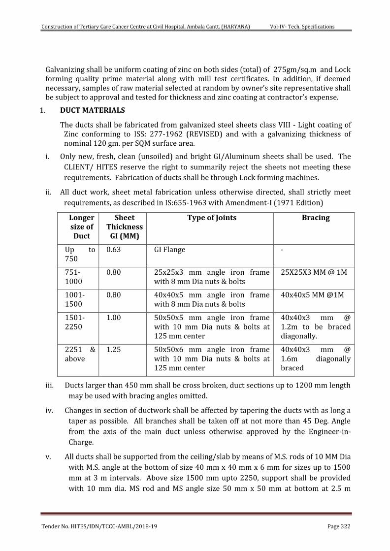
Construction of Tertiary Care Cancer Centre at Civil Hospital, Ambala Cantt. (HARYANA) Vol-IV- Tech. Specifications
Tender No. HITES/IDN/TCCC-AMBL/2018-19 Page 322
Galvanizing shall be uniform coating of zinc on both sides (total) of 275gm/sq.m and Lock forming quality prime material along with mill test certificates. In addition, if deemed necessary, samples of raw material selected at random by owner’s site representative shall be subject to approval and tested for thickness and zinc coating at contractor’s expense.
1. DUCT MATERIALS
The ducts shall be fabricated from galvanized steel sheets class VIII - Light coating of Zinc conforming to ISS: 277-1962 (REVISED) and with a galvanizing thickness of nominal 120 gm. per SQM surface area.
i. Only new, fresh, clean (unsoiled) and bright GI/Aluminum sheets shall be used. The
CLIENT/ HITES reserve the right to summarily reject the sheets not meeting these
requirements. Fabrication of ducts shall be through Lock forming machines.
ii. All duct work, sheet metal fabrication unless otherwise directed, shall strictly meet
requirements, as described in IS:655-1963 with Amendment-I (1971 Edition)
Longer size of Duct
Sheet Thickness
GI (MM)
Type of Joints Bracing
Up to 750
0.63 GI Flange -
751-1000
0.80 25x25x3 mm angle iron frame with 8 mm Dia nuts & bolts
25X25X3 MM @ 1M
1001-1500
0.80 40x40x5 mm angle iron frame with 8 mm Dia nuts & bolts
40x40x5 MM @1M
1501-2250
1.00 50x50x5 mm angle iron frame with 10 mm Dia nuts & bolts at 125 mm center
40x40x3 mm @ 1.2m to be braced diagonally.
2251 & above
1.25 50x50x6 mm angle iron frame with 10 mm Dia nuts & bolts at 125 mm center
40x40x3 mm @ 1.6m diagonally braced
iii. Ducts larger than 450 mm shall be cross broken, duct sections up to 1200 mm length
may be used with bracing angles omitted.
iv. Changes in section of ductwork shall be affected by tapering the ducts with as long a
taper as possible. All branches shall be taken off at not more than 45 Deg. Angle
from the axis of the main duct unless otherwise approved by the Engineer-in-
Charge.
v. All ducts shall be supported from the ceiling/slab by means of M.S. rods of 10 MM Dia
with M.S. angle at the bottom of size 40 mm x 40 mm x 6 mm for sizes up to 1500
mm at 3 m intervals. Above size 1500 mm upto 2250, support shall be provided
with 10 mm dia. MS rod and MS angle size 50 mm x 50 mm at bottom at 2.5 m
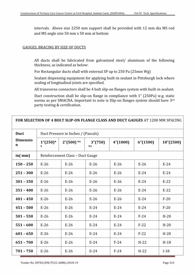
Construction of Tertiary Care Cancer Centre at Civil Hospital, Ambala Cantt. (HARYANA) Vol-IV- Tech. Specifications
Tender No. HITES/IDN/TCCC-AMBL/2018-19 Page 323
intervals. Above size 2250 mm support shall be provided with 12 mm dia MS rod
and MS angle size 50 mm x 50 mm at bottom
GAUGES, BRACING BY SIZE OF DUCTS
All ducts shall be fabricated from galvanized steel/ aluminum of the following thickness, as indicated as below:
For Rectangular ducts shall with external SP up to 250 Pa (25mm Wg)
Sealant dispensing equipment for applying built-in sealant in Pittsburgh lock where sealing of longitudinal joints are specified.
All transverse connectors shall be 4 bolt slip-on flanges system with built-in sealant.
Duct construction shall be slip-on flange in compliance with 1” (250Pa) w.g. static norms as per SMACNA. Important to note is Slip-on flanges system should have 3rd party testing & certification.
FOR SELECTION OF 4 BOLT SLIP-ON FLANGE CLASS AND DUCT GAUGES AT 1200 MM SPACING
Duct
Dimension
Duct Pressure in Inches / (Pascals)
1"(250)*5
2”(500) *4 3”(750) *3
4”(1000) 6"(1500) 10”(2500)
in( mm) Reinforcement Class – Duct Gauge
150 – 250 E-26 E-26 E-26 E-26 E-26 E-24
251 – 300 E-26 E-26 E-26 E-26 E-24 E-24
301 – 350 E-26 E-26 E-26 E-26 E-24 E-22
351 – 400 E-26 E-26 E-26 E-26 E-24 E-22
401 – 450 E-26 E-26 E-26 E-26 E-24 F-20
451 – 500 E-26 E-26 E-24 E-24 E-24 F-20
501 – 550 E-26 E-26 E-24 E-24 F-24 H-20
551 – 600 E-26 E-26 E-24 E-24 F-22 H-20
601 – 650 E-26 E-26 E-24 E-24 F-22 H-20
651 – 700 E-26 E-26 E-24 F-24 H-22 H-18
701 – 750 E-26 E-26 E-24 F-24 H-22 I-18
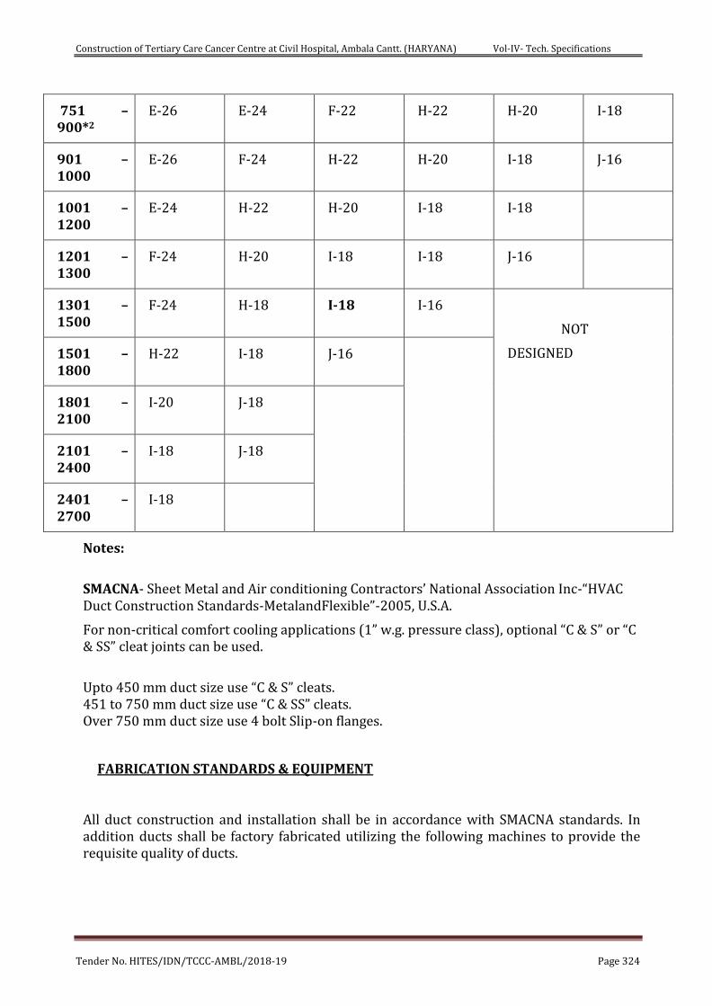
Construction of Tertiary Care Cancer Centre at Civil Hospital, Ambala Cantt. (HARYANA) Vol-IV- Tech. Specifications
Tender No. HITES/IDN/TCCC-AMBL/2018-19 Page 324
751 – 900*2
E-26 E-24 F-22 H-22 H-20 I-18
901 – 1000
E-26 F-24 H-22 H-20 I-18 J-16
1001 – 1200
E-24 H-22 H-20 I-18 I-18
1201 – 1300
F-24 H-20 I-18 I-18 J-16
1301 – 1500
F-24 H-18 I-18 I-16
NOT
DESIGNED 1501 – 1800
H-22 I-18 J-16
1801 – 2100
I-20 J-18
2101 – 2400
I-18 J-18
2401 – 2700
I-18
Notes:
SMACNA- Sheet Metal and Air conditioning Contractors’ National Association Inc-“HVAC Duct Construction Standards-MetalandFlexible”-2005, U.S.A.
For non-critical comfort cooling applications (1” w.g. pressure class), optional “C & S” or “C & SS” cleat joints can be used.
Upto 450 mm duct size use “C & S” cleats. 451 to 750 mm duct size use “C & SS” cleats. Over 750 mm duct size use 4 bolt Slip-on flanges.
FABRICATION STANDARDS & EQUIPMENT
All duct construction and installation shall be in accordance with SMACNA standards. In addition ducts shall be factory fabricated utilizing the following machines to provide the requisite quality of ducts.
Construction of Tertiary Care Cancer Centre at Civil Hospital, Ambala Cantt. (HARYANA) Vol-IV- Tech. Specifications
Tender No. HITES/IDN/TCCC-AMBL/2018-19 Page 325
1. A coil (Sheet metal in Roll Form) line to facilitate location of longitudinal seams at
corners/folded edges only, for required duct rigidity and leakage free
characteristics. No longitudinal seams permitted along any face side of the duct.
2. All ducts, transformation pieces and fittings to be made on CNC profile cutters for
required accuracy of dimensions, location and dimensions of notches at the folding
lines.
3. All edges to be machine treated using lock formers, flangers and rollers for turning
up edges.
4. Kitchen exhaust ducting shall be with 16 G MS suitable access doors shall be
provided at every 3 m. Provision shall be made for firefighting agency to install duct
mounted sprinklers at every 3m. Generally exhaust duct shall have slop towards
kitchen hood.
DUCT CONSTRUCTION
All ducts shall be fabricated and installed in workmanlike manner, conforming to relevant SMACNA codes:
a) Ducts so identified on the Drawings shall be acoustically lined and insulated from
outside as described in the section “Insulation” and as indicated in schedule of
quantities. Duct dimension shown in the drawings, are overall sheet metal
dimensions inclusive of the acoustic lining where required and indicated in
schedule of quantities. The fabricated duct dimensions should be as per approved
drawings and care should be taken to ensure that all connecting sections are
dimensionally matched to avoid any gaps.
b) Ducts shall be straight and smooth on the inside with longitudinal seams shall be air
either Pittsburgh or snap button as per SMACNA practice, to ensure air tightness.
c) All ducts up to 75 cms width within conditioned spaces shall have slip and drive
(C&S/SS) joints. The internal ends of slip joints shall be in the direction of airflow.
Care should be taken ensure that S/SS cleats are mounted on the longer side of the
duct and cleats on the shorter side. Ducts more than 75cms width shall have 4 bolt
slip-on flanges. Ducts and accessories within the ceiling spaces, visible from air-
conditioned areas shall be provided with two coats of mat black finish paint.
d) Changes in dimensions and shape of ducts shall be gradual (between 1:4 and 1:7).
Air-vanes shall be installed in all bends and duct collars designed to permit the air
to make the turn without appreciable turbulence.
Construction of Tertiary Care Cancer Centre at Civil Hospital, Ambala Cantt. (HARYANA) Vol-IV- Tech. Specifications
Tender No. HITES/IDN/TCCC-AMBL/2018-19 Page 326
e) Ducts shall be fabricated as per details shown on drawings. All ducts shall be rigid
and shall adequately supported and braced where required with standing seams,
tees or angles, of ample size to keep the ducts true to shape and to prevent buckling,
vibration or breathing.
f) All sheet metal connections, partitions and plenums required to confine the flow of
air to and through the filters and fans, shall be constructed of 18G GSS/16G
Aluminum, thoroughly stiffened with 25mm x 25mm x 3mm galvanized steel angle
braces and fitted with all necessary inspection doors as required, to give access to
all parts of the apparatus. Access doors shall be not less than 45cm x 45cm in size.
g) Plenums shall be shop/factory fabricated panel type and assemble at site. Fixing of
galvanized angle flanges on the duct pieces shall be with rivets heads inside i.e.
towards GS sheet and riveting shall be done from outside.
h) Self-adhesive Polyethylene lining of minimum 4.5mm thickness instead of felt shall
be used between duct flanges and between duct supports in all ducting installation.
3. ACCESSORIES:
All dampers, except where shown, shall be louver dampers having multiple opposed
blades type or with parallel blades of airfoil construction. The construction of the
dampers shall be robust and tight fitting. They should be made from 18 gauge
galvanized sheets. The depth should be minimum of 150mm and flanges of 40mm.
Blades shall be connected with a suitable linkage for operation by an extending by an
extending lever, which shall have a locking quadrant with positions of the damper
indicated on it. Dampers and their operating device shall be made robust, easily
operable and accessible through suitable access doors in the ducts.
Dampers shall be provided in ducts at every branch supply or return air duct
connections whether or not indicated on the drawings for the proper volume control
and balancing the system.
Where shown, splitter dampers shall be installed. This damper consists of double
thickness airfoil blade hinged on the downstream edge. The operating lever shall
extend outside the duct and insulation with an airtight hub and locking arrangements.
The thickness of the damper blades shall be the same as the duct in which they are
installed but not less than 1.5mm thickness.
Fire dampers shall be motorized / solenoid type wherever specified shall be provide in
the ducts to minimize spreading of fire through ducts, i.e. points where duct passes fire
Construction of Tertiary Care Cancer Centre at Civil Hospital, Ambala Cantt. (HARYANA) Vol-IV- Tech. Specifications
Tender No. HITES/IDN/TCCC-AMBL/2018-19 Page 327
(rated 1 ½ hrs. or more) wall or slab. Fire dampers shall be 230mm – deep and face
area as required. The outlet casing of the damper shall be fabricated out of 12 gauges
M.S. sheet duly epoxy painted with two coats. The louvers shall be provided with
smooth pivoted linkage, tripping mechanism of steel bar with heavy-duty spring
assembly and provision of motor. The louvers to be arranged to pivot and hold in an
open position and can be closed by an electrically operated motor. The damper is used
in conjunction with a smoke alarm system. The entire assembly shall be duly epoxy
primer of 2 coats (epoxy paint) or aluminum spray painted. The dampers shall be
designed for automatic as well as manual tripping.
Motors shall be rated for fire damper (spring to close power to open) operation and shall
be suitable for outdoor installation (IP55). Fire dampers are closed on a signal from the
fire control module. Module supply and wiring by fire control contractor.
Motorised dampers should be single flap dampers with 18 gauge construction with
Belimo or Equivalent make spring return type. Opening time should be more than
75secs. And closing time should be 30secs. The power shall be given from the electrical
panel and will be routed through the unit.
300mm X 300mm access panels with gasket neoprene and stud bolt type shall be
provided near lower dampers/ splitters dampers and fire damper. All main ducting
work shall be accessible throughout using tight fitted hinged access doors. Doors shall
be cemented sponge rubber gaskets of 6mm thickness. Felt is not acceptable. In the
case of insulated ducts with access doors, the same shall be properly insulated, such
that it can be operated without damaging the duct insulation and there should be no
condensation either on the access doors or on the ducts when he plant is running.
4. INSTALLATION GUIDELINES
The duct fabrication and installation shall generally confirm to IS 655-1963.
All ducts shall be supported from the concrete slab or beams. Duct supports shall be
fixed through the use of two anchor fasteners for each leg. The anchor fasteners shall be
of approved make. If ducting is supported from steel structure, Beam Clamps shall be
provided. In no case shall the duct be supported from the false ceiling hangers or be
permitted to rest on a hung ceiling.
Transverse joints shall be provided with rubber gaskets (6mm thk.) of nonflammable
type. Use of felt shall not be permitted.
Wherever the ducts are acoustically lined, the duct size shall be increased by the
thickness of the duct lining.
The contractor shall provide and neatly erect all sheet metal work as per the
specifications and drawings. This work ,in all its parts and details, shall meet with the
approval of the Engineer
The contractor shall make all necessary allowances and provisions for beams, pipes or
other obstructions in the ducting, whether or not the same has been shown in the
Construction of Tertiary Care Cancer Centre at Civil Hospital, Ambala Cantt. (HARYANA) Vol-IV- Tech. Specifications
Tender No. HITES/IDN/TCCC-AMBL/2018-19 Page 328
drawings. Wherever necessary to avoid beams or other structural works, plumbing or
other pipes / conduits, the ducts shall be transformed, divided or curved to one side as
approved or directed by the Engineer. However the required cross-sectional area shall
be maintained.
All metal work shall be done in dead or furred down spaces so as not to cause any delay
to other contractors on the building.
If a duct cannot be installed as shown in the drawings, the contractor shall install the
duct between the required points by any path available subject to the approval of the
Engineer and Architect.
All ducts shall be rigid and shall be adequately supported with standing seams, tees or
angles of ample size wherever required to keep the ducts true to shape, prevent
buckling, vibration and breathing.
All duct joints shall be tightly fitted using rubber gasket of nonflammable type and all
interior surfaces shall be smooth. Bends shall be made with radius not less than one-
half of the width of the duct or with properly designed interior curved vanes. Two
vanes shall be spaced such that the aspect ratio of each of the individual elbows formed
by the vane will be about five to one.
All sheet metal connections, partitions and plenums required to confine the flow of air to
and through the filters and fans, shall be constructed from 16G galvanised iron
thoroughly stiffened with 25mm X 25mm angle iron braces and fitted with all
necessary doors as required to give access to all parts of the apparatus. Doors shall not
be less than 46 cm X 71cm. Sheet Metal connections to indoor units shall be flexible,
double thickness fiberglass cloth or equivalent nonflammable material of 100mm long.
Where metal ducts or sleeves terminate in woodwork, brick or masonry openings tight
joints shall be made by the means of closely fittings heavy flanged collars.
Resistoflex or similar vibration isolation material of 6mm thickness shall be provided
between ducts and duct support.
Where ductwork is connected to rotating equipment duct such as fans, air handling units
(indoor unit of split/package system), the connections shall be made with double
thickness nonflammable flexible material, 100mm long.
5. GRILLES AND DIFFUSERS:
Supply Air Side Wall Outlets
Wherever specified in the B.O.Q. shall be in Aluminum construction.
Double Deflection Grilles:
Wherever specified in the B.O.Q. shall be in Aluminum construction. Aluminum double
deflection grills for supply air shall be provided with vertical and horizontal adjustable
bars and an approved blade damper adjustable from the front face of the grille. The
Construction of Tertiary Care Cancer Centre at Civil Hospital, Ambala Cantt. (HARYANA) Vol-IV- Tech. Specifications
Tender No. HITES/IDN/TCCC-AMBL/2018-19 Page 329
grilles will be powder -coated in a shade as given in the schedule of finishes of this
handbook.
Fixed Bar Linear Grilles
Fixed bar grilles will be in extruded aluminum construction. Bars shall be fixed in position using vertical tie bars. Bar spacing shall not exceed 12mm and the grilles shall have 60% free area. Deflection angle of the bars shall be 0. The grilles will be powder coated in a shade as per the owner/architect. Irrespective of grille finish, vertical tie bars shall be powder coated in Matt black. Supply air outlets shall be provided with volume control dampers to be installed in the duct collar. Dampers shall be in black Matt powder coated finish. Where required by the Architects/Consultants, the grilles shall be provided with a margin on all sides. Supply air outlets shall be provided with end closure pieces for the supply portion of the grille. The end closure pieces shall not come to the grille face.
• Continuous grilles shall butt with hairline joints and be provided with interlocking splines.
• All return air grilles shall be similar and equal to the above as determined by consultants.
• All exhaust air grilles shall be similar and equal to the supply air grilles specified above.
6. CEILING OUTLETS:
Square / Rectangular Diffusers:
Shall be of aluminum construction wherever specified in the BOQ. Corners of inner and outer cores shall be assembled to provide precise mitered corners. Supply air diffusers shall be provided with multi blade butterfly dampers. Damper flaps shall be provided with a nylon worm gear assembly for ease of operation. Diffusers will be powder -coated in a shade as approved by client/Architect. Diffuser shall be half step down type.
7. GUIDELINES FOR INSTALLATION OF GRILLES/DIFFUSERS
Installation of the grilles/diffusers shall be done by the air conditioning contractor irrespective of the type/model of false ceiling systems .The diffusers will have to be individually suspended from the duct and aligned to match the ceiling line level. In case gypsum or any other false ceiling system, all wooden frames, rectangular or circular for supply/return/exhaust air diffusers will be provided by the Air conditioning contractor.
All air outlets/return air inlets in the same room shall be of the same size unless otherwise specified.
Grilles and diffuser samples must be submitted to the consultants for prior approval before procurement and installation.
Wire Hangers shall be used to suspend all static HVAC services.
Wire Hangers should consist of a pre-formed wire rope sling with a range of end fixings to fit fixings, these include a ferruled loop, permanently fixed threaded M6 (or M8, M10) stud, permanently fixed nipple end with toggle, at one end or hook or eyelet, cladding hook, barrel, wedge anchor, eyebolt anchor or any other end fixture type or size as per
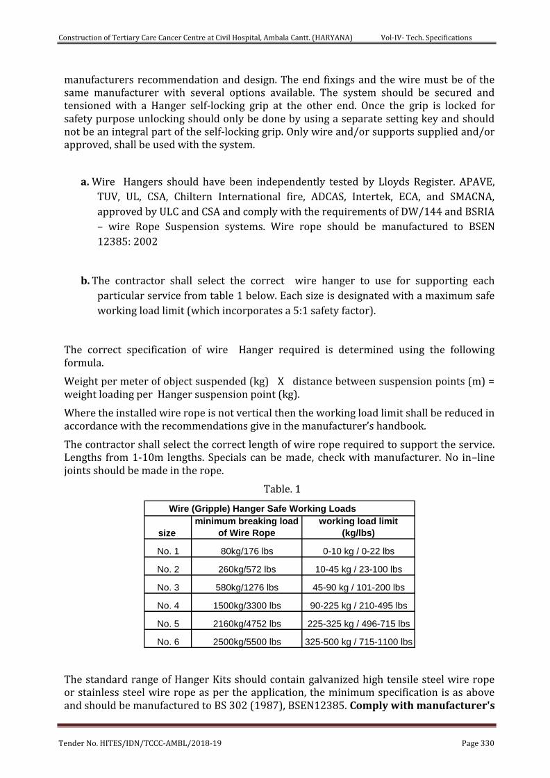
Construction of Tertiary Care Cancer Centre at Civil Hospital, Ambala Cantt. (HARYANA) Vol-IV- Tech. Specifications
Tender No. HITES/IDN/TCCC-AMBL/2018-19 Page 330
manufacturers recommendation and design. The end fixings and the wire must be of the same manufacturer with several options available. The system should be secured and tensioned with a Hanger self-locking grip at the other end. Once the grip is locked for safety purpose unlocking should only be done by using a separate setting key and should not be an integral part of the self-locking grip. Only wire and/or supports supplied and/or approved, shall be used with the system.
a. Wire Hangers should have been independently tested by Lloyds Register. APAVE,
TUV, UL, CSA, Chiltern International fire, ADCAS, Intertek, ECA, and SMACNA,
approved by ULC and CSA and comply with the requirements of DW/144 and BSRIA
– wire Rope Suspension systems. Wire rope should be manufactured to BSEN
12385: 2002
b. The contractor shall select the correct wire hanger to use for supporting each
particular service from table 1 below. Each size is designated with a maximum safe
working load limit (which incorporates a 5:1 safety factor).
The correct specification of wire Hanger required is determined using the following formula.
Weight per meter of object suspended (kg) X distance between suspension points (m) = weight loading per Hanger suspension point (kg).
Where the installed wire rope is not vertical then the working load limit shall be reduced in accordance with the recommendations give in the manufacturer’s handbook.
The contractor shall select the correct length of wire rope required to support the service. Lengths from 1-10m lengths. Specials can be made, check with manufacturer. No in–line joints should be made in the rope.
Table. 1
Wire (Gripple) Hanger Safe Working Loads
size
minimum breaking load
of Wire Rope
working load limit
(kg/lbs)
No. 1 80kg/176 lbs 0-10 kg / 0-22 lbs
No. 2 260kg/572 lbs 10-45 kg / 23-100 lbs
No. 3 580kg/1276 lbs 45-90 kg / 101-200 lbs
No. 4 1500kg/3300 lbs 90-225 kg / 210-495 lbs
No. 5 2160kg/4752 lbs 225-325 kg / 496-715 lbs
No. 6 2500kg/5500 lbs 325-500 kg / 715-1100 lbs
The standard range of Hanger Kits should contain galvanized high tensile steel wire rope or stainless steel wire rope as per the application, the minimum specification is as above and should be manufactured to BS 302 (1987), BSEN12385. Comply with manufacturer's
Construction of Tertiary Care Cancer Centre at Civil Hospital, Ambala Cantt. (HARYANA) Vol-IV- Tech. Specifications
Tender No. HITES/IDN/TCCC-AMBL/2018-19 Page 331
load ratings and recommended installation procedures. Note the testing is done to the minimum breaking load of the wire thus giving a minimum safety factor of 5: 1.
Ducting Supports:
a) All ductwork shall be independently supported from building construction. All
horizontal ducts shall be rigidly and securely supported, in an approved manner,
with hangers formed of galvanized steel wire ropes and galvanized steel
angle/channel or a pair of brackets, connected by galvanized steel wire hangers
under ducts, rigid supports may be provided at certain interval if need be. The
spacing between supports should be not greater than 2.4 meter. All vertical
ductwork shall be supported by structural members on each floor slab. Duct
supports may be through galvanized steel insert plates or Toggle end wire
fixing left in slab at the time of slab casting. Galvanized steel cleat with a hole for
passing the wire rope hanger shall be welded to the plates. Trapeze hanger
formed of galvanized steel wire rope using Gripple shall be hung through these
cleats. Wherever use of metal insert plates is not feasible, duct support shall be
through dash/anchor fastener driven into the concrete slab by electrically
operated gun. Wire rope supports shall hang through the cleats or wire rope
threaded studs can be screwed into the anchor fasteners.
All horizontal ducts shall be adequately secured and supported. In an approved manner, with trapeze Hangers formed of galvanized steel wire rope in a cradle support method (refer to typical drawings) under ducts at no greater than 2000mm centre, for above 2000-2250mm 50x50x5 mm angle should be used under the duct (refer to typical drawings), above 2250mm appropriate size angle should be used with prior approval. All vertical duct work shall be supported by structural members on each floor slab. Duct support shall be through dash / anchor fastener driven into the concrete slab by electrically operated gun. Hanger wires shall then hang around the ducting. Rigid supports shall be used in conjunction with wire rope hangers to assist with alignment of services where recommended for by the manufacturer. Rigid support must also be used in conjunction with wire rope hangers with duct work at each change of direction or connection. Support ducting in accordance with Schedule I at the end of this Section. Any other Gripple solution can be used based on manufacturer’s recommendation on site conditions after prior approval. In cases of Spiral ducting the wire can be wrapped directly around the ducting without the need for a spiral ducting clamp for sizes above 1100 a cradle support should be provided refer to manufacturer’s recommendations.
Ducting over furred ceiling shall be supported from the slab above or from beams after obtaining approval of Construction manager/consultant. In no case shall any duct be supported from false ceiling Hangers or be permitted to rest on false ceiling. All metal work in dead or furred down spaces shall be erected in time to occasion no delay to other Contractor’s work in the building. All supports of pipe shall be taken from structural slab/wall by means of fastener.
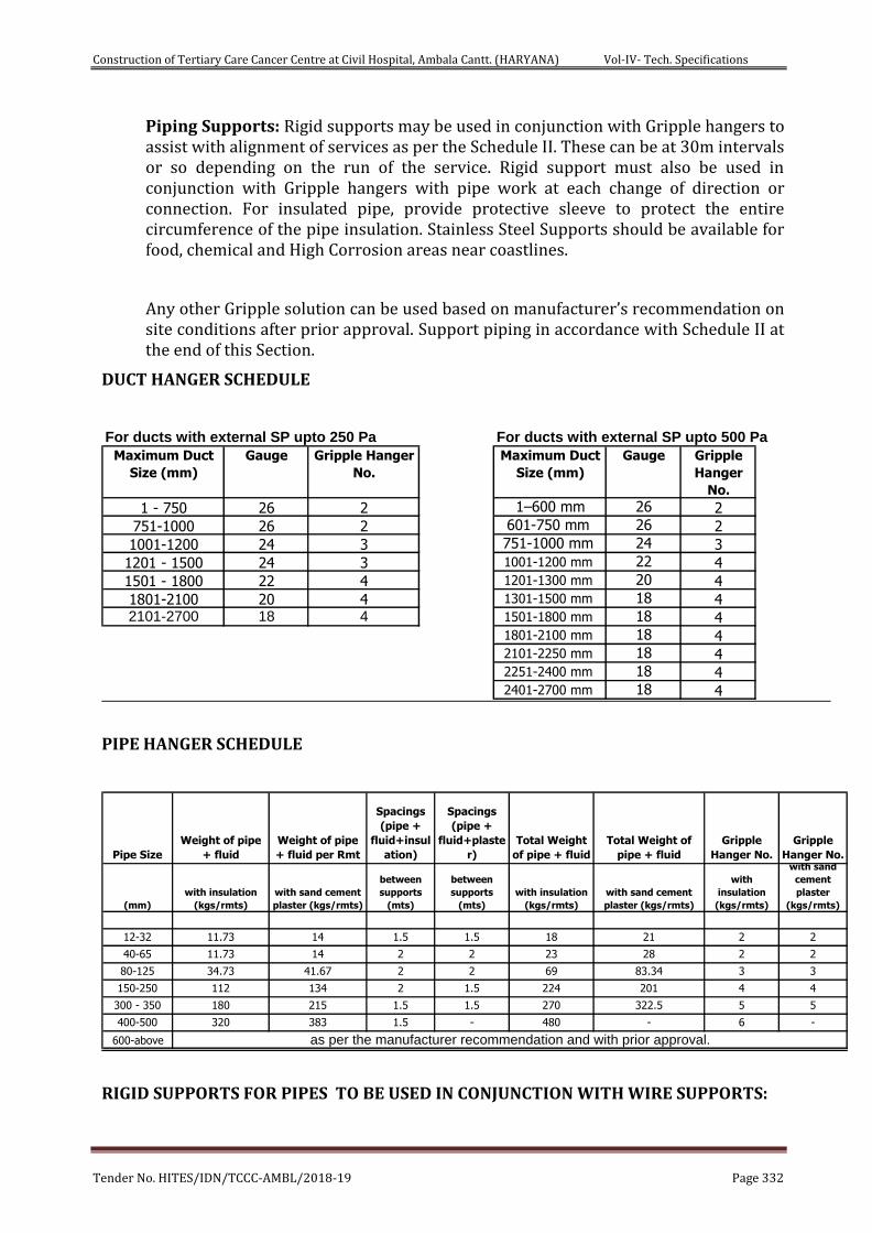
Construction of Tertiary Care Cancer Centre at Civil Hospital, Ambala Cantt. (HARYANA) Vol-IV- Tech. Specifications
Tender No. HITES/IDN/TCCC-AMBL/2018-19 Page 332
Piping Supports: Rigid supports may be used in conjunction with Gripple hangers to assist with alignment of services as per the Schedule II. These can be at 30m intervals or so depending on the run of the service. Rigid support must also be used in conjunction with Gripple hangers with pipe work at each change of direction or connection. For insulated pipe, provide protective sleeve to protect the entire circumference of the pipe insulation. Stainless Steel Supports should be available for food, chemical and High Corrosion areas near coastlines.
Any other Gripple solution can be used based on manufacturer’s recommendation on site conditions after prior approval. Support piping in accordance with Schedule II at the end of this Section.
DUCT HANGER SCHEDULE
For ducts with external SP upto 500 Pa
Maximum Duct
Size (mm)
Gauge Gripple Hanger
No.
Maximum Duct
Size (mm)
Gauge Gripple
Hanger
No.
1 - 750 26 2 1–600 mm 26 2
751-1000 26 2 601-750 mm 26 2
1001-1200 24 3 751-1000 mm 24 3
1201 - 1500 24 3 1001-1200 mm 22 4
1501 - 1800 22 4 1201-1300 mm 20 4
1801-2100 20 4 1301-1500 mm 18 42101-2700 18 4 1501-1800 mm 18 4
1801-2100 mm 18 42101-2250 mm 18 42251-2400 mm 18 42401-2700 mm 18 4
For ducts with external SP upto 250 Pa
PIPE HANGER SCHEDULE
Pipe Size
Weight of pipe
+ fluid
Weight of pipe
+ fluid per Rmt
Spacings
(pipe +
fluid+insul
ation)
Spacings
(pipe +
fluid+plaste
r)
Total Weight
of pipe + fluid
Total Weight of
pipe + fluid
Gripple
Hanger No.
Gripple
Hanger No.
(mm)
with insulation
(kgs/rmts)
with sand cement
plaster (kgs/rmts)
between
supports
(mts)
between
supports
(mts)
with insulation
(kgs/rmts)
with sand cement
plaster (kgs/rmts)
with
insulation
(kgs/rmts)
with sand
cement
plaster
(kgs/rmts)
12-32 11.73 14 1.5 1.5 18 21 2 2
40-65 11.73 14 2 2 23 28 2 2
80-125 34.73 41.67 2 2 69 83.34 3 3
150-250 112 134 2 1.5 224 201 4 4
300 - 350 180 215 1.5 1.5 270 322.5 5 5
400-500 320 383 1.5 - 480 - 6 -
600-above as per the manufacturer recommendation and with prior approval.
RIGID SUPPORTS FOR PIPES TO BE USED IN CONJUNCTION WITH WIRE SUPPORTS:
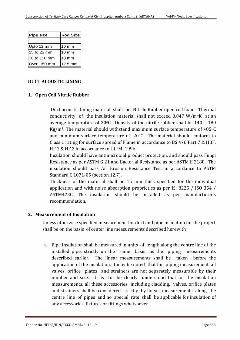
Construction of Tertiary Care Cancer Centre at Civil Hospital, Ambala Cantt. (HARYANA) Vol-IV- Tech. Specifications
Tender No. HITES/IDN/TCCC-AMBL/2018-19 Page 333
Pipe size Rod Size
Upto 12 mm 10 mm
15 to 25 mm 10 mm
30 to 150 mm 10 mm
Over 150 mm 12.5 mm
DUCT ACOUSTIC LINING
1. Open Cell Nitrile Rubber
Duct acoustic lining material shall be Nitrile Rubber open cell foam. Thermal
conductivity of the insulation material shall not exceed 0.047 W/moK at an
average temperature of 20oC. Density of the nitrile rubber shall be 140 – 180
Kg/m3. The material should withstand maximum surface temperature of +85oC
and minimum surface temperature of -20oC. The material should conform to
Class 1 rating for surface spread of Flame in accordance to BS 476 Part 7 & HBF,
HF 1 & HF 2 in accordance to UL 94, 1996.
Insulation should have antimicrobial product protection, and should pass Fungi
Resistance as per ASTM G 21 and Bacterial Resistance as per ASTM E 2180. The
insulation should pass Air Erosion Resistance Test in accordance to ASTM
Standard C 1071-05 (section 12.7).
Thickness of the material shall be 15 mm thick specified for the individual
application and with noise absorption proprieties as per IS: 8225 / ISO 354 /
ASTM423C. The insulation should be installed as per manufacturer’s
recommendation.
2. Measurement of Insulation
Unless otherwise specified measurement for duct and pipe insulation for the project
shall be on the basis of center line measurements described herewith
a. Pipe Insulation shall be measured in units of length along the centre line of the
installed pipe, strictly on the same basis as the piping measurements
described earlier. The linear measurements shall be taken before the
application of the insulation. It may be noted that for piping measurement, all
valves, orifice plates and strainers are not separately measurable by their
number and size. It is to be clearly understood that for the insulation
measurements, all these accessories including cladding, valves, orifice plates
and strainers shall be considered strictly by linear measurements along the
centre line of pipes and no special rate shall be applicable for insulation of
any accessories, fixtures or fittings whatsoever.
Construction of Tertiary Care Cancer Centre at Civil Hospital, Ambala Cantt. (HARYANA) Vol-IV- Tech. Specifications
Tender No. HITES/IDN/TCCC-AMBL/2018-19 Page 334
b. Duct Insulation and Acoustic Lining shall be measured on the basis of surface
area along the centre line of insulation thickness. Thus the surface area of
externally thermally insulated or acoustically lined be based on the perimeter
comprising centre line (of thickness of insulation) width and depth of the
cross section of insulated or lined duct, multiplied by the centre-line length
including tapered pieces, bends, tees, branches, etc. as measured for bare
ducting.
3. Duct Insulation Material
Thermal insulation material for Duct insulation shall be with factory
laminated black fiber glass cloth closed cell Elastomeric UV resistant or Plain
polyethylene material. Thermal conductivity as per BS 874 part 2 – 86 (DIN
52613 52612) / DIN EN 12667 / EN ISO8497 of the insulation material
shall not exceed 0.038 W/moK or 0.212 BTU / (Hr-ft2-oF/inch) at an average
temperature of 30oC. Density of the nitrile rubber shall be 40-60 Kg/m3 &
for polyethylene material it shall be 25-30 Kg/m3 and shall be plain material.
The product shall have temperature range of –40 oC to 105oC.
The insulation material shall be fire rated for Class 0 as per BS 476 Part 6 :
1989 for fire propagation test and for Class 1 as per BS 476 Part 7, 1987 for
surface spread of flame test. Water vapour permeability shall be not less
than 0.024 per inch (2.48 x 10⁻¹³ Kg/m.s.Pa i.e. µ>7000: Water vapour
diffusion resistance) as per DIN 53122 part 2, DIN 52615 / EN 12086 &
EN13469.
In addition to above properties the insulation material for ducts shall be
anti-microbial. Microbiological growth on insulation surface shall be in
accordance with ASTM G-21 and bacterial resistance to ASTM2180.
The Material shall comply to ISO 5659 / BS 6853 / ABD 0031 for smoke
density and toxicity values. The thermal conductivity of insulation material
shall not be effected by aging as per DIN 52616 standard.
Thickness of the insulation shall be as specified for the individual
application. Each lot of insulation material delivered at site shall be
accompanied with manufacturer’s test certificate for density and thickness.
Samples of insulation material from each lot delivered at site may be selected
by Owner’s site representative and gotten tested for thermal conductivity
and density at Contractor’s cost. Adhesive used for sealing the insulation
shall be non-flammable and with low VOC content (maximum 850 gm/l as
per IGBC guide lines) strictly as per manufacturer’s recommendations.
DUCTING INSULATION THICKNESS SHALL BE AS PER TABLE BELOW.
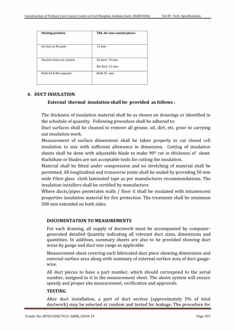
Construction of Tertiary Care Cancer Centre at Civil Hospital, Ambala Cantt. (HARYANA) Vol-IV- Tech. Specifications
Tender No. HITES/IDN/TCCC-AMBL/2018-19 Page 335
Ducting position
Thk. for non-coastal places
SA duct in RA path
13 mm
Ducted return air system SA duct: 19 mm
RA duct: 13 mm
Both SA & RA exposed
Both 25 mm
4. DUCT INSULATION
External thermal insulation shall be provided as follows :
The thickness of insulation material shall be as shown on drawings or identified in
the schedule of quantity. Following procedure shall be adhered to:
Duct surfaces shall be cleaned to remove all grease, oil, dirt, etc. prior to carrying
out insulation work.
Measurement of surface dimensions shall be taken properly to cut closed cell
insulation to size with sufficient allowance in dimension. Cutting of insulation
sheets shall be done with adjustable blade to make 900 cut in thickness of sheet.
Hackshaw or blades are not acceptable tools for cutting the insulation.
Material shall be fitted under compression and no stretching of material shall be
permitted. All longitudinal and transverse joints shall be sealed by providing 50 mm
wide Fibre glass cloth laminated tape as per manufacturer recommendations. The
insulation installers shall be certified by manufacture.
Where ducts/pipes penetrates walls / floor it shall be insulated with intumescent
properties insulation material for fire protection. The treatment shall be minimum
500 mm extended on both sides.
DOCUMENTATION TO MEASUREMENTS
For each drawing, all supply of ductwork must be accompanied by computer-generated detailed Quantity indicating all relevant duct sizes, dimensions and quantities. In addition, summary sheets are also to be provided showing duct areas by gauge and duct size range as applicable.
Measurement sheet covering each fabricated duct piece showing dimensions and external surface area along with summary of external surface area of duct gauge-wise.
All duct pieces to have a part number, which should correspond to the serial number, assigned to it in the measurement sheet. The above system will ensure speedy and proper site measurement, verification and approvals.
TESTING
After duct installation, a part of duct section (approximately 5% of total ductwork) may be selected at random and tested for leakage. The procedure for
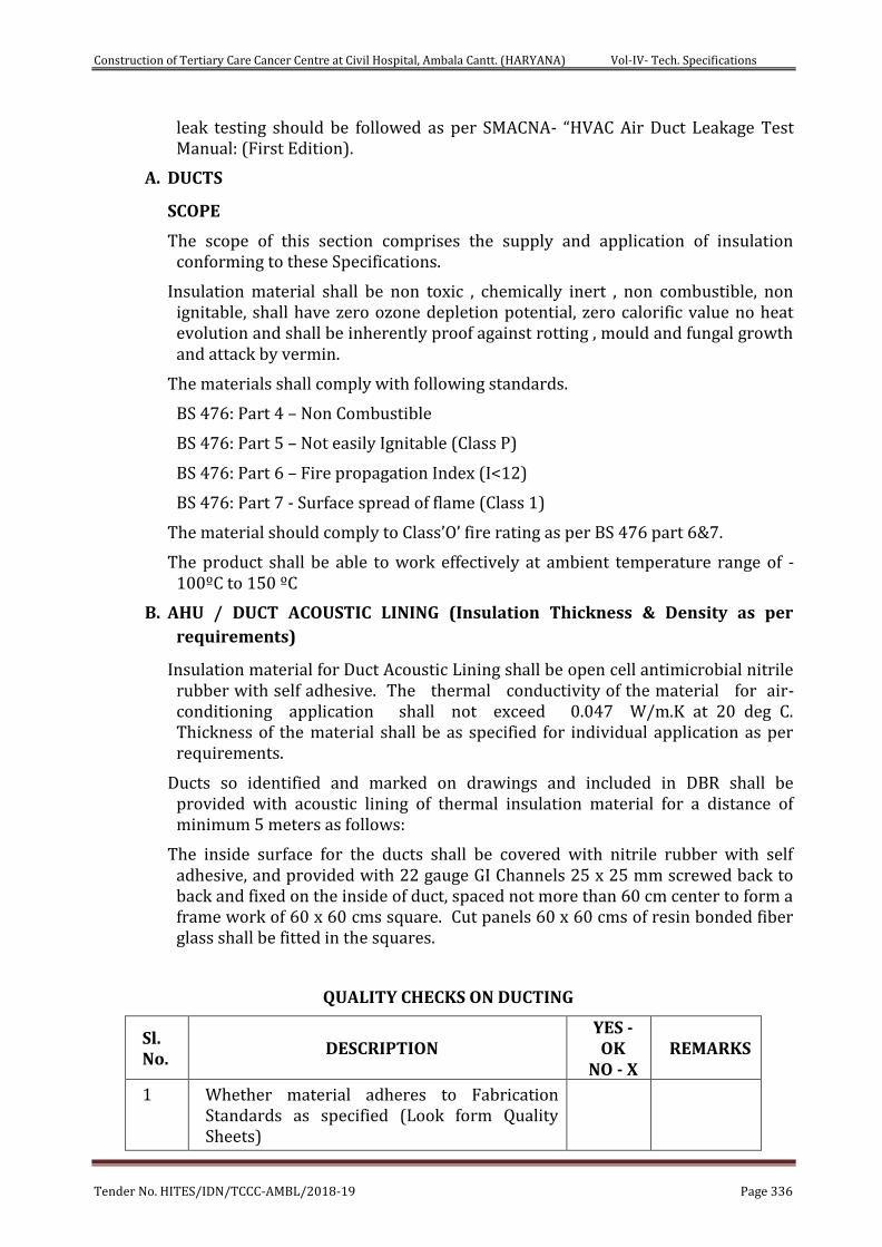
Construction of Tertiary Care Cancer Centre at Civil Hospital, Ambala Cantt. (HARYANA) Vol-IV- Tech. Specifications
Tender No. HITES/IDN/TCCC-AMBL/2018-19 Page 336
leak testing should be followed as per SMACNA- “HVAC Air Duct Leakage Test Manual: (First Edition).
A. DUCTS
SCOPE
The scope of this section comprises the supply and application of insulation conforming to these Specifications.
Insulation material shall be non toxic , chemically inert , non combustible, non ignitable, shall have zero ozone depletion potential, zero calorific value no heat evolution and shall be inherently proof against rotting , mould and fungal growth and attack by vermin.
The materials shall comply with following standards.
BS 476: Part 4 – Non Combustible
BS 476: Part 5 – Not easily Ignitable (Class P)
BS 476: Part 6 – Fire propagation Index (I<12)
BS 476: Part 7 - Surface spread of flame (Class 1)
The material should comply to Class’O’ fire rating as per BS 476 part 6&7.
The product shall be able to work effectively at ambient temperature range of -100ºC to 150 ºC
B. AHU / DUCT ACOUSTIC LINING (Insulation Thickness & Density as per
requirements)
Insulation material for Duct Acoustic Lining shall be open cell antimicrobial nitrile rubber with self adhesive. The thermal conductivity of the material for air-conditioning application shall not exceed 0.047 W/m.K at 20 deg C. Thickness of the material shall be as specified for individual application as per requirements.
Ducts so identified and marked on drawings and included in DBR shall be provided with acoustic lining of thermal insulation material for a distance of minimum 5 meters as follows:
The inside surface for the ducts shall be covered with nitrile rubber with self adhesive, and provided with 22 gauge GI Channels 25 x 25 mm screwed back to back and fixed on the inside of duct, spaced not more than 60 cm center to form a frame work of 60 x 60 cms square. Cut panels 60 x 60 cms of resin bonded fiber glass shall be fitted in the squares.
QUALITY CHECKS ON DUCTING
Sl. No.
DESCRIPTION YES - OK
NO - X REMARKS
1 Whether material adheres to Fabrication Standards as specified (Look form Quality Sheets)
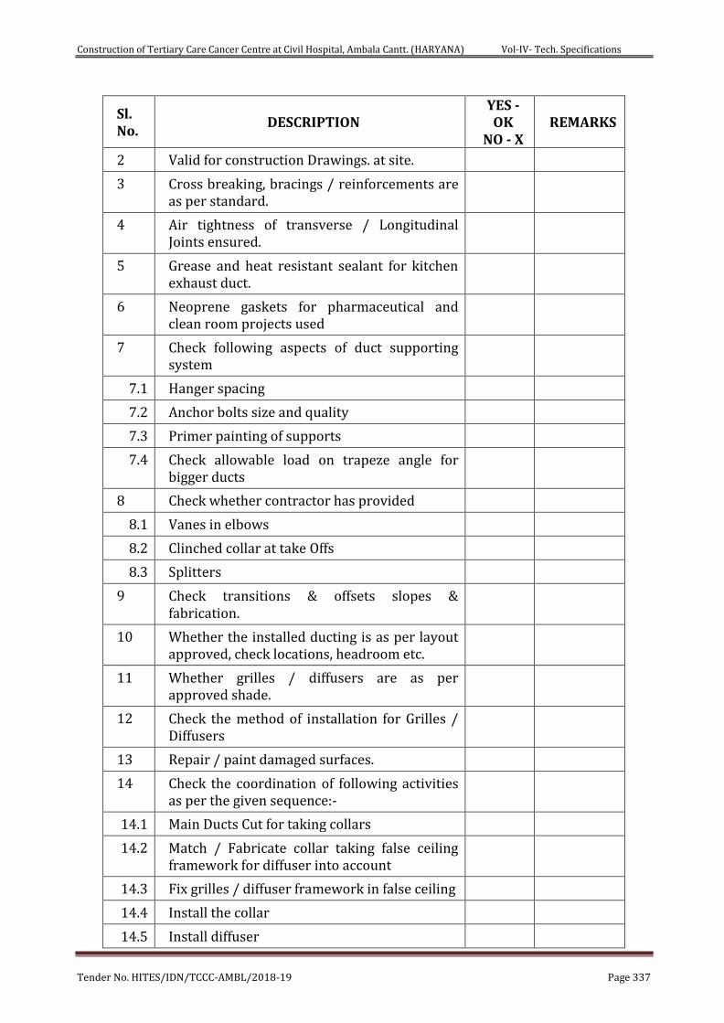
Construction of Tertiary Care Cancer Centre at Civil Hospital, Ambala Cantt. (HARYANA) Vol-IV- Tech. Specifications
Tender No. HITES/IDN/TCCC-AMBL/2018-19 Page 337
Sl. No.
DESCRIPTION YES - OK
NO - X REMARKS
2 Valid for construction Drawings. at site.
3 Cross breaking, bracings / reinforcements are as per standard.
4 Air tightness of transverse / Longitudinal Joints ensured.
5 Grease and heat resistant sealant for kitchen exhaust duct.
6 Neoprene gaskets for pharmaceutical and clean room projects used
7 Check following aspects of duct supporting system
7.1 Hanger spacing
7.2 Anchor bolts size and quality
7.3 Primer painting of supports
7.4 Check allowable load on trapeze angle for bigger ducts
8 Check whether contractor has provided
8.1 Vanes in elbows
8.2 Clinched collar at take Offs
8.3 Splitters
9 Check transitions & offsets slopes & fabrication.
10 Whether the installed ducting is as per layout approved, check locations, headroom etc.
11 Whether grilles / diffusers are as per approved shade.
12 Check the method of installation for Grilles / Diffusers
13 Repair / paint damaged surfaces.
14 Check the coordination of following activities as per the given sequence:-
14.1 Main Ducts Cut for taking collars
14.2 Match / Fabricate collar taking false ceiling framework for diffuser into account
14.3 Fix grilles / diffuser framework in false ceiling
14.4 Install the collar
14.5 Install diffuser
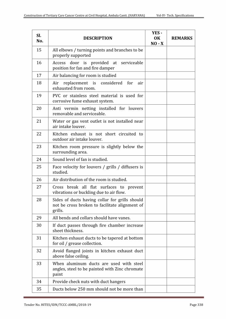
Construction of Tertiary Care Cancer Centre at Civil Hospital, Ambala Cantt. (HARYANA) Vol-IV- Tech. Specifications
Tender No. HITES/IDN/TCCC-AMBL/2018-19 Page 338
Sl. No.
DESCRIPTION YES - OK
NO - X REMARKS
15 All elbows / turning points and branches to be properly supported
16 Access door is provided at serviceable position for fan and fire damper
17 Air balancing for room is studied
18 Air replacement is considered for air exhausted from room.
19 PVC or stainless steel material is used for corrosive fume exhaust system.
20 Anti vermin netting installed for louvers removable and serviceable.
21 Water or gas vent outlet is not installed near air intake louver.
22 Kitchen exhaust is not short circuited to outdoor air intake louver.
23 Kitchen room pressure is slightly below the surrounding area.
24 Sound level of fan is studied.
25 Face velocity for louvers / grills / diffusers is studied.
26 Air distribution of the room is studied.
27 Cross break all flat surfaces to prevent vibrations or buckling due to air flow.
28 Sides of ducts having collar for grills should not be cross broken to facilitate alignment of grills.
29 All bends and collars should have vanes.
30 If duct passes through fire chamber increase sheet thickness.
31 Kitchen exhaust ducts to be tapered at bottom for oil / grease collection.
32 Avoid flanged joints in kitchen exhaust duct above false ceiling.
33 When aluminum ducts are used with steel angles, steel to be painted with Zinc chromate paint
34 Provide check nuts with duct hangers
35 Ducts below 250 mm should not be more than
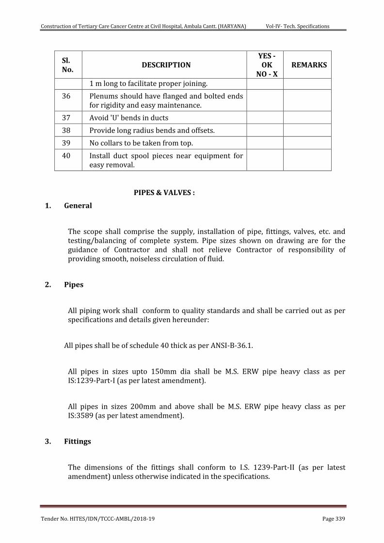
Construction of Tertiary Care Cancer Centre at Civil Hospital, Ambala Cantt. (HARYANA) Vol-IV- Tech. Specifications
Tender No. HITES/IDN/TCCC-AMBL/2018-19 Page 339
Sl. No.
DESCRIPTION YES - OK
NO - X REMARKS
1 m long to facilitate proper joining.
36 Plenums should have flanged and bolted ends for rigidity and easy maintenance.
37 Avoid 'U' bends in ducts
38 Provide long radius bends and offsets.
39 No collars to be taken from top.
40 Install duct spool pieces near equipment for easy removal.
PIPES & VALVES :
1. General
The scope shall comprise the supply, installation of pipe, fittings, valves, etc. and testing/balancing of complete system. Pipe sizes shown on drawing are for the guidance of Contractor and shall not relieve Contractor of responsibility of providing smooth, noiseless circulation of fluid.
2. Pipes
All piping work shall conform to quality standards and shall be carried out as per specifications and details given hereunder:
All pipes shall be of schedule 40 thick as per ANSI-B-36.1.
All pipes in sizes upto 150mm dia shall be M.S. ERW pipe heavy class as per IS:1239-Part-I (as per latest amendment).
All pipes in sizes 200mm and above shall be M.S. ERW pipe heavy class as per IS:3589 (as per latest amendment).
3. Fittings
The dimensions of the fittings shall conform to I.S. 1239-Part-II (as per latest amendment) unless otherwise indicated in the specifications.
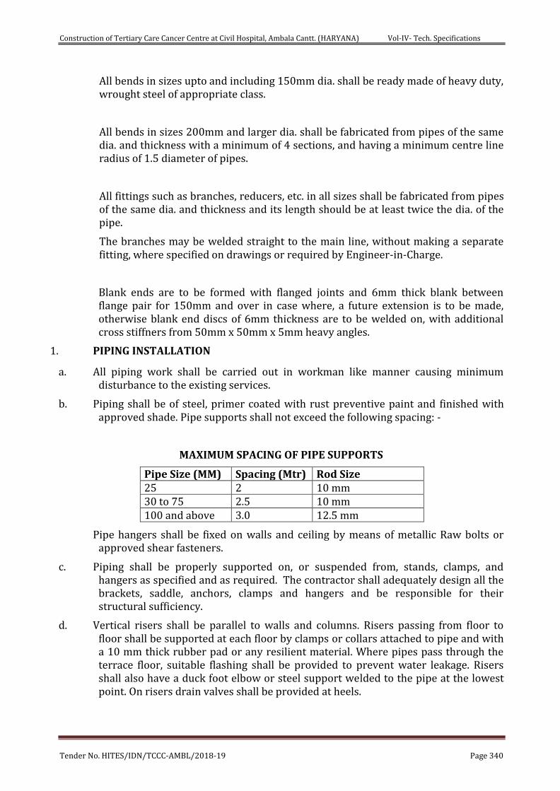
Construction of Tertiary Care Cancer Centre at Civil Hospital, Ambala Cantt. (HARYANA) Vol-IV- Tech. Specifications
Tender No. HITES/IDN/TCCC-AMBL/2018-19 Page 340
All bends in sizes upto and including 150mm dia. shall be ready made of heavy duty, wrought steel of appropriate class.
All bends in sizes 200mm and larger dia. shall be fabricated from pipes of the same dia. and thickness with a minimum of 4 sections, and having a minimum centre line radius of 1.5 diameter of pipes.
All fittings such as branches, reducers, etc. in all sizes shall be fabricated from pipes of the same dia. and thickness and its length should be at least twice the dia. of the pipe.
The branches may be welded straight to the main line, without making a separate fitting, where specified on drawings or required by Engineer-in-Charge.
Blank ends are to be formed with flanged joints and 6mm thick blank between flange pair for 150mm and over in case where, a future extension is to be made, otherwise blank end discs of 6mm thickness are to be welded on, with additional cross stiffners from 50mm x 50mm x 5mm heavy angles.
1. PIPING INSTALLATION
a. All piping work shall be carried out in workman like manner causing minimum disturbance to the existing services.
b. Piping shall be of steel, primer coated with rust preventive paint and finished with approved shade. Pipe supports shall not exceed the following spacing: -
MAXIMUM SPACING OF PIPE SUPPORTS
Pipe Size (MM) Spacing (Mtr) Rod Size 25 2 10 mm 30 to 75 2.5 10 mm 100 and above 3.0 12.5 mm
Pipe hangers shall be fixed on walls and ceiling by means of metallic Raw bolts or approved shear fasteners.
c. Piping shall be properly supported on, or suspended from, stands, clamps, and hangers as specified and as required. The contractor shall adequately design all the brackets, saddle, anchors, clamps and hangers and be responsible for their structural sufficiency.
d. Vertical risers shall be parallel to walls and columns. Risers passing from floor to floor shall be supported at each floor by clamps or collars attached to pipe and with a 10 mm thick rubber pad or any resilient material. Where pipes pass through the terrace floor, suitable flashing shall be provided to prevent water leakage. Risers shall also have a duck foot elbow or steel support welded to the pipe at the lowest point. On risers drain valves shall be provided at heels.
Construction of Tertiary Care Cancer Centre at Civil Hospital, Ambala Cantt. (HARYANA) Vol-IV- Tech. Specifications
Tender No. HITES/IDN/TCCC-AMBL/2018-19 Page 341
e. Pipe sleeve of 50 mm larger than the pipe diameter shall be provided wherever pipes pass through walls and the annular space filled with felt and finished with retaining rings. In case of an insulated pipe the diameter shall be inclusive of insulation.
f. Insulated piping shall be supported in such a manner as not to put undue pressure on the insulation. Metal sheet shall be provided between the insulation and clamp, saddle or roller extending at least 150 mm on both sides of clamp, saddle or roller.
4. Flanges
All flanges shall be of mild steel as per IS: 6392/71 and shall be steel slip-on-type, welded to the pipes flanges thickness shall be to suit class-II pressures. Flanges may be tack welded into position, but all final welding shall be done with joints dismounted. 3mm thick gaskets shall be used with all flanged joints. The gaskets shall be fibre reinforced rubber as approved by the Engineer-in-Charge. Special adhesive compound shall be used between flanges of steam, air and gas lines.
Flanges shall be used as used as follows:
Counter flanges for equipment having flanged connections.
Flanged pairs shall be used on all such equipment, which is required to be isolated or removed for service e.g. pumps, refrigeration machines, air handling units, etc.
All threaded valves shall be provided with nipples and flanged pairs on both sides to permit flange connection, for removal of valves from main lines for repair/replacement.
5. Valves
a) Butterfly Valves, Gate Valves, Globe Valves and Check Valves:
All gate valves, globe and check valves upto and including 40mm dia. Shall be of gun metal screwed type, conforming to class 1 of IS:778.
All butterfly valves of 50mm dia. and above shall be flanged type, have cast iron body with black nitrile rubber seat and conforming to class PN-16 of IS:780 (for sizes upto 300mm) and of IS:2906 (for sizes 350mm and above).
All globe and check valve of 50mm dia. and above shall be flanged type in cast iron construction and conforming to class PN-16.
Construction of Tertiary Care Cancer Centre at Civil Hospital, Ambala Cantt. (HARYANA) Vol-IV- Tech. Specifications
Tender No. HITES/IDN/TCCC-AMBL/2018-19 Page 342
Air valves shall be provided at all higher points in the piping system for venting as per the sizes shown in the BOQ.
All air needle valves shall be of gun metal and tested upto a pressure of class 1 pressure rating. All globe valves of size 50mm and above shall be of rising spindle type.
b) Balancing Valves
All balancing valves of upto and including 50 mm dia. shall be in gun metal screwed type construction. The valves of 65 mm dia. and above shall be in cast iron flanged end construction.
The valve shall have PTFE/SS disc with special erosion/ corrosion proof sealing.
The valves shall be capable of delivering metered quantity of water and subsequently should function as isolating valve. All the valves shall have built in pressure drop measuring facility to ascertain water flow rate. The valves shall have temper proof adjustable and lockable arrangement for required water quantity after commissioning. The valve shall be to the minimum requirement of IS: 778 Class-1.
The valves shall be complete with drain cock, pressure test cocks, etc.
c) Miscellaneous Valves
All gauge cocks shall be of gunmetal plug type, complete with siphon (brass chrome plated).
All drain valves shall be of gunmetal with a hose union connection on one end or extended upto the drain pit as the case may be.
All valves on the supply line of fan coil units shall be of gunmetal ball type with integral water strainers, having (BSP) FPT inlet and flare type MPT outlet connection.
All valves on the return line of fan coil units shall be as above but without integral water strainer.
d) Strainers
The strainers shall either be 'pot' type or 'Y' type with cast iron or fabricated steel body, tested to a pressure of 10 kg/sq.cm. Applicable for the butterfly valves as shown on the drawings.
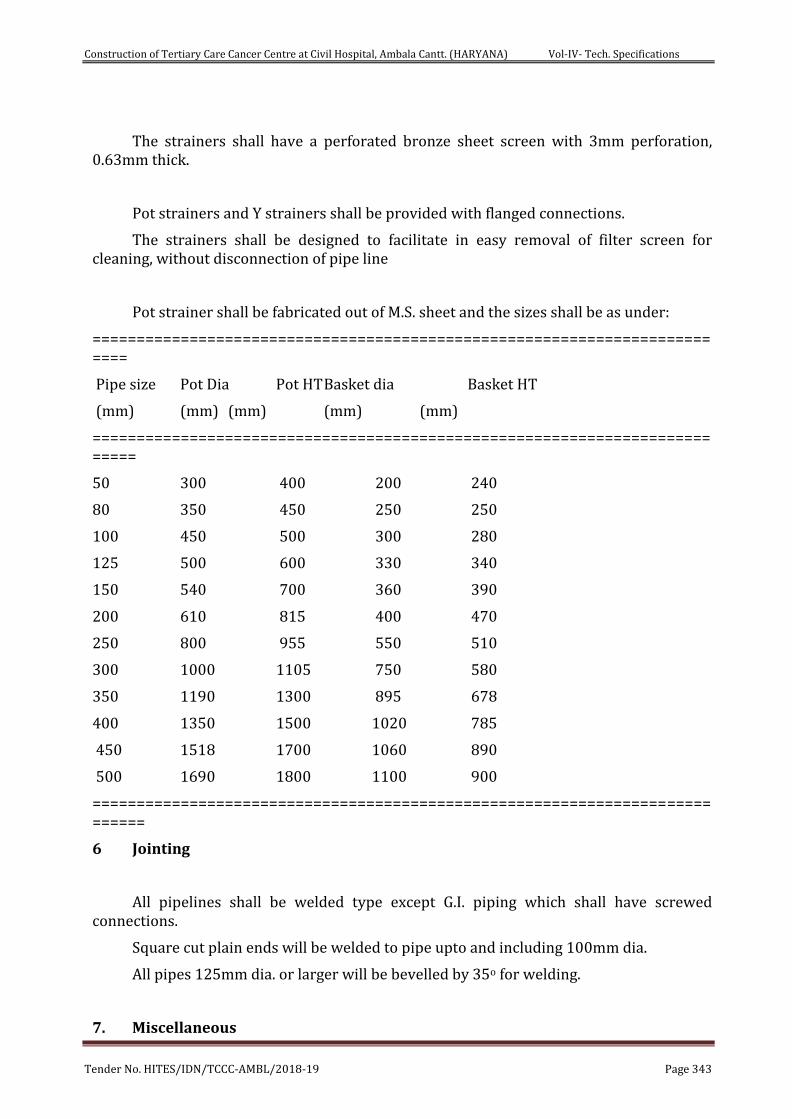
Construction of Tertiary Care Cancer Centre at Civil Hospital, Ambala Cantt. (HARYANA) Vol-IV- Tech. Specifications
Tender No. HITES/IDN/TCCC-AMBL/2018-19 Page 343
The strainers shall have a perforated bronze sheet screen with 3mm perforation, 0.63mm thick.
Pot strainers and Y strainers shall be provided with flanged connections.
The strainers shall be designed to facilitate in easy removal of filter screen for cleaning, without disconnection of pipe line
Pot strainer shall be fabricated out of M.S. sheet and the sizes shall be as under:
==========================================================================
Pipe size Pot Dia Pot HT Basket dia Basket HT
(mm) (mm) (mm) (mm) (mm)
===========================================================================
50 300 400 200 240
80 350 450 250 250
100 450 500 300 280
125 500 600 330 340
150 540 700 360 390
200 610 815 400 470
250 800 955 550 510
300 1000 1105 750 580
350 1190 1300 895 678
400 1350 1500 1020 785
450 1518 1700 1060 890
500 1690 1800 1100 900
============================================================================
6 Jointing
All pipelines shall be welded type except G.I. piping which shall have screwed connections.
Square cut plain ends will be welded to pipe upto and including 100mm dia.
All pipes 125mm dia. or larger will be bevelled by 35o for welding.
7. Miscellaneous
Construction of Tertiary Care Cancer Centre at Civil Hospital, Ambala Cantt. (HARYANA) Vol-IV- Tech. Specifications
Tender No. HITES/IDN/TCCC-AMBL/2018-19 Page 344
a) Provide all piping, required to make the apparatus connected, complete and ready for regular and safe operation. Unless otherwise noted, connect all apparatus and equipment in accordance with manufacturer's standard details, as approved by Engineer-in-Charge.
Consult drawings and specifications to determine number and requirements of all items of equipment requiring piping, such as bend, drain, relief, etc. wherever equipment is provided with connections for such piping.
b) Unless otherwise specified, pitch the lines of piping as follows:
All condensation drainage, including air handling unit and fan coil unit shall be pitched in the direction of flow to ensure adequate drainage, with an adequate trap seal to prevent leakage of air due to static pressure developed by air conditioning units. Pitch, 20mm per metre wherever possible, but not less than 10mm. Drains from other equipment shall be pitched similarly without trap seal.
c) Provide valves and capped connections for all low points in piping system, necessary or required for draining systems. Provide for all risers isolating valves and drain valves to permit repairs without interfering with the rest of the system
d) During construction, temporarily close, open ends of pipes with sheet metal caps, where necessary, or required to prevent debris from entering piping system.
e) Support piping independently of all equipment so that the equipment is not stressed by the piping weight or expansion.
f) Provide suitable platforms, etc. to facilitate the maintenance-repair and replacement of valves and fittings.
g) Unions, if used, shall be flanged, as required, wherever indicated and in connections to all equipment, apparatus, and specialties requiring disconnection for repairs or replacement. Locate unions between shut-off valves and equipment, as directed by Engineer-in-Charge.
h) Provide shut-off valves where indicated and for individual equipment, units at inlet and outlet, to permit unit removal for repairs, without interfering with remaining of the system. Additional shut-off valves shall be provided as required to enable all systems to be fully sectionalized. By-pass and stop valves shall be provided for all automatic control valves as specified
Construction of Tertiary Care Cancer Centre at Civil Hospital, Ambala Cantt. (HARYANA) Vol-IV- Tech. Specifications
Tender No. HITES/IDN/TCCC-AMBL/2018-19 Page 345
i) Arrange piping for maximum accessibility for maintenance and repair; locate valves for easy access and operation. No valves shall be installed with handles pointing down, unless unavoidable.
j) Cut the pipes accurately according to measurements, established at building and work into place without springing or forcing.
k) Pipe supports shall be adjustable for height and prime coated with rust preventive paint and finish coated with grey paint, both as approved by Engineer-in-Charge. Spacing of pipe supports shall not be more than that as specified below:
======================================================================================
Nominal pipe size Spacing
(MM) (Meters)
=======================================================================================
15 1.25
20 & 25 2.00
32, 40, 50 & 65 2.50
80, 100 & 125 2.50
150 & above 2.50 ==============================================================================
l) Extra supports shall be provided at the bends, and at heavy fittings like valves to avoid undue stresses on the pipes. Pipe hangers shall be fixed on walls and ceilings by means of metallic dash fasteners.
m) Insulated piping shall be supported in such a manner so as not to put undue pressure on the insulation.
Hangers and supports shall be provided and installed for all piping and tubing wherever indicated, required or otherwise specified. Wherever necessary, additional hangers and supports shall be provided to prevent vibration or excessive deflection of piping and tubing.
All hangers and supports shall be made of steel or other durable and non-combustible materials, galvanized or plated. Wood, wire or perforated strap iron shall not be used as permanent hangers or supports.
Hangers shall be supported from structural steel, concrete inserts and pipe racks, specifically approved.
No hanger/equipment shall be suspended midway, between steel joists and panel points.
Construction of Tertiary Care Cancer Centre at Civil Hospital, Ambala Cantt. (HARYANA) Vol-IV- Tech. Specifications
Tender No. HITES/IDN/TCCC-AMBL/2018-19 Page 346
Drilling or punching of holes in steel joist members will not be permitted.
All pipes in AC plant room shall be supported from pipes and channels from floor.
9 Sleeves
Where pipes pass through walls, provide galvanized steel pipe sleeves 50mm larger than outside diameter of pipe without any extra cost. Where pipes are insulated, sleeves shall be large enough to have ample clearance for insulation.
Where pipes pass through outside walls or floor slab the space between pipe and sleeve shall be packed with lead wool and oakum.
The centre of pipes shall be in the centre of sleeves and sleeves shall be flush with the finished surface. Floor sleeves shall project 50mm above finished floor level.
10 Expansion or Contraction
The Contractor shall provide for expansion and contraction of all piping installed by the use of swing connections and expansion loops.
11 Arrangement and Alignment of Piping
All piping shall be arranged and aligned in accordance with the drawings as specified. Where special conditions are encountered in the field, the arrangement and alignment of piping shall be as directed by the Engineer-in-charge.
Unless otherwise specified, the piping shall be installed in a uniform manner, parallel to or perpendicular to walls or ceilings, and all changes in directions shall be made with fittings. The horizontal piping shall be run at right angles and shall not run diagonally across rooms or other piping. Wherever possible all piping shall be arranged to provide a maximum head room.
All piping shall be installed as directly as possible between connecting points in so far as the work of other trades permits. Where interference occurs with another trade whose work is more difficult to route, this contractor shall reroute his pipes as required to avoid interference at the discretion of the Engineer-in-Charge.
All piping shall be carefully installed to provide for proper alignment, slope and expansion.
The stresses in pipelines shall be guided and pipes shall be supported in such a manner that pipe lines shall not creep, sag or buckle.
Anchors and supports shall be provided wherever necessary to prevent any misalignment of piping.
Construction of Tertiary Care Cancer Centre at Civil Hospital, Ambala Cantt. (HARYANA) Vol-IV- Tech. Specifications
Tender No. HITES/IDN/TCCC-AMBL/2018-19 Page 347
Small tubing, gauges, controls or other equipment installed on any apparatus, shall not be coiled or excessive in length, but shall be installed neatly, carefully bent at all changes in direction, secured in place and properly fastened to equipment at intervals to prevent sagging. The piping shall be grouped wherever practical and shall be installed uniformly in straight parallel lines in either vertical or horizontal positions. All tubing/capillaries shall be provided with PVC sleeves to save it against frictional cuts or damage due to vibration.
12 Testing
In general, tests shall be applied to piping before connection of equipment and appliances. In no case shall piping equipment or appliances be subjected to pressures exceeding their test rating.
The tests shall be completed and approved before any insulation is applied. Testing of segments of pipe work will be permitted, provided all open ends are first closed, by blank-offs or flanges.
After tests have been completed, the system shall be drained and flushed 3 to 4 times and cleaned of all dust and foreign matter. All strainers, valves and fittings shall be cleaned of all dirt, fillings and debris.
All piping shall be tested to hydraulic test pressure of at least two times the maximum operating pressure but less than 10 kg/sq. cm. for a period of not less than 24 hours. All leaks and defects in the joints revealed during the testing shall be rectified to the satisfaction of the Engineer-in-Charge, without any extra cost.
All the piping systems shall be tested in the presence of the Engineer-in-Charge or their authorized representative. Advance notice of test dates shall be given and all Equipments, labour, material required for inspection, and repairs during the test shall be provided by the contractor. A test shall be repeated till the entire system is found satisfactory to the above authority. The tests shall be carried out for a part of work if required by the Engineer-in-Charge in order to avoid hindrances in the work of the insulation contractor.
All water and condensate pipes shall be tested and proven tight under hydrostatic pressure of 10 kg/sq.cm. Unless otherwise stated, for a minimum period of 24 hours without drop in pressure.
The Contractor shall make sure that proper noiseless circulation is achieved through all piping systems. If due to poor air bond, proper circulation is not achieved, the contractor shall bear all expenses for carrying out the rectification work including finishing of floors, walls and ceiling damaged in the process of rectification.
Construction of Tertiary Care Cancer Centre at Civil Hospital, Ambala Cantt. (HARYANA) Vol-IV- Tech. Specifications
Tender No. HITES/IDN/TCCC-AMBL/2018-19 Page 348
The Contractor shall provide all labors and materials to make provision for removing water and throwing it at the proper place during the testing or/and after the testing to avoid damages to employer or other contractors properties. Any damage caused by the contractor to the employer or other contractors properties, shall be borne by the Contractor.
13. Copper Piping
Heavy gauge soft copper tubing, type M, shall be used to make connections to equipment, wherever required or specified by Engineer-in-Charge.
Flare fittings e.g. flare nuts, tees, elbows, reducers, etc. shall all be of brass.
14. Refrigerant Piping
The refrigerant circuit piping shall be of carbon steel seamless, as per ASTMA-106, grade B or BS-3602 grade 23 and dimensioned as per ANSI B-36.1, schedule 40. The fittings shall be heavy class. The pipes and fittings shall be connected by means of welded joints. The connections to gauges, controls, etc. shall be with flare fittings. The refrigerant valves, required in the circuit shall be as follows:
Valve Size Valve Material Type of Connections fittings
=====================================================================
Upto 12mm Brass packless type Flare
16mm and above Brass/Steel packed Brazed/Welded type
=====================================================================
Note :- All valves shall be tested against leaks upto 28 kg/sq.cm.
The strainers for the refrigerant liquid line shall be 'Y' type with gun metal body and bronze filter screen of fine mesh. The filter screen shall be easily removable type without dismantling the strainer from the circuit. The moisture indication sight glass in the liquid line shall have leak proof glass on opposite sides to permit easy inspection of the liquid refrigerant. Silencers and moisture drier etc. shall be provided as part of the refrigerant piping.
Bolts wherever used shall be electro-galvanized steel. Brazed joints, in the refrigerant piping, which has leak, shall be opened and re-done. These shall in, no case be repaired by addition of brazing alloy to the joint.
Construction of Tertiary Care Cancer Centre at Civil Hospital, Ambala Cantt. (HARYANA) Vol-IV- Tech. Specifications
Tender No. HITES/IDN/TCCC-AMBL/2018-19 Page 349
15. Drain Piping
The drain piping shall be medium class galvanized steel as per IS: 1239 (as per latest amendment).
The fittings shall be of as per IS: 1239 Part-II with screwed connections.
The gate valves shall be of gun metal as described earlier.
Pipe crosses shall be provided at bends, to permit easy cleaning of drain line. The drain line shall be provided upto the nearest drain trap and pitched towards the trap.
Drain lines shall be provided at all the lowest points in the system, as well as at Equipments where leakage of water is likely to occur, or to remove condensate and water from pump glands. The drain pipe work shall be carried out with threaded joints only. No welded joint shall be permissible.
16. Painting
All pipes supports, hangers, etc., shall be given two coats of red oxide primer.
All pipes (insulated and non insulated) shall then be given two coats finish paint, of a type and color as approved by the Engineer-in-Charge.
DUCT AND PIPE INSULATION
Ductwork shall be insulated as per the below specified guidelines.
Painting
Angle iron Flanges, Stiffeners, hangers and supports shall be painted with 2 coats of anti-rust primer and remaining uncovered duct shall be further painted with 2 coats of synthetic enamel paints of black color.
Testing and Balancing
After completion of ducting work, system shall be tested for air leakage. Leakage if any shall be plugged and all the adjustments and balancing are completed. The air quantity readings shall be recorded. All dampers shall be set and locked in position after the final adjustments. All readings made shall be submitted to the consultants for approval.
Ductwork & Piping Insulation Application Guidelines :
Construction of Tertiary Care Cancer Centre at Civil Hospital, Ambala Cantt. (HARYANA) Vol-IV- Tech. Specifications
Tender No. HITES/IDN/TCCC-AMBL/2018-19 Page 350
Piping and accessory insulation application shall be as follows:
Pipes shall be thoroughly cleaned with wire brush and rendered free from all rust and
grease.
For insulation of straight pipe slip on method shall be used. For elbows and bends snap
off method will be used.
First 2 coats of specified Insulation adhesive shall be applied then the Insulation shall
be fixed tightly on the surface taking care to seal all joints .
Adequately sized PVC self-adhesive tape shall be provided to seal all joints afterwards
Al cladding shall be done as per requirements.
DUCT INSULATION
MATERIAL
Insulation material shall be Closed Cell Elastomeric Nitrile Rubber
Thermal conductivity of elastomeric nitrile rubber shall not exceed 0.033 W/(m.K)
at mean temperature of 0C
Insulation material shall have anti-microbial product, which is EPA (Environmental
Protection Agency), USA approved, as an integral part of insulation which cannot be
washed off or worn off.
It shall give enhanced level of protection against harmful Microbes such as bacteria,
mold, mildew and fungi and shall confirm to following standards: Fungi Resistance
– ASTM G21 and Bacterial resistance – ASTM G 22 / ASTM 2180.
The insulation shall have fire performance such that it passes Class 1 as per BS476
Part 7 for surface spread of flame as per BS 476 and also pass Fire Propagation
requirement as per BS476 Part 6 to meet the Class ‘O’ Fire category as per 1991
Building Regulations (England & Wales) and the Building Standards (Scotland)
Regulations 1990 as well the National Building code (NBC) of india.
Material shall be FM (Factory Mutual), USA approved.
Moisture Diffusion Resistance Factor or ‘µ’ value shall be minimum 10,000.
The insulation thickness shall be 9 mm on all ducts except the toilet and basement exhaust.
PIPE WORK INSULATION:
All chilled water and drain pipes Insulation shall be as follows.The material will be TF quality Expanded polystyrenene of 20kg/m3 density minimum.
Upto 100 mm pipe size - 50 mm
Above 100 mm pipe size - 75 mm
Construction of Tertiary Care Cancer Centre at Civil Hospital, Ambala Cantt. (HARYANA) Vol-IV- Tech. Specifications
Tender No. HITES/IDN/TCCC-AMBL/2018-19 Page 351
CONTROLS
1. General :
1.1 The various controls listed below shall be electrically operated and generally comply
with the specifications listed below:
1.2 In case of low voltage controls necessary step down transformers shall be provided
with each control as required.
2. Chilling Unit Control:
The Chilling machines controls shall be generally standard as per the selected manufacturer standards.
3. Air Handling Unit and Fan Coil Unit controls:
3.1 AHUs thermostats shall be cooling/heating suitable for mounting in the room or the
return path as required. The thermostat shall be modulating potentiometer type
with an adjustable throttling range and required accuracy.
3.2 2- way motorised Valve for AHUs :
The motorised water valve shall be globe type and consist of CI/gunmetal valve body with SS trim and equal percentage of flow charcteristics, modulating motor and linkage.The valve shall be of 3 way mixing type.
3.2 The thermostat for Fan coil unit shall be space type for cooling. It shall be snap acting type , line voltage, murcury bulb type with differential of 1.1 C. It shall have minimum three speed control complete with wiring etc.
3.3 The water pressure guages shall be of robust construction 150 mm dial of suitable
range and occupancy range.
3.4 The thermometers shall be murcurry filled industrial stem type with metal casing
and threaded fixing arrangement.
NOISE & VIBRATION CONTROL
Construction of Tertiary Care Cancer Centre at Civil Hospital, Ambala Cantt. (HARYANA) Vol-IV- Tech. Specifications
Tender No. HITES/IDN/TCCC-AMBL/2018-19 Page 352
1. SCOPE OF WORK
This section deals with design, supply, installation, testing and commissioning of noise and vibration control equipment and accessories.
2. STANDARDS
The testing of all noise control equipment and the methods used in measuring the noise rating of air conditioning plant and equipment shall be in accordance with the relevant sections of the following British Standards, unless otherwise stated:
BS 4718: 1971 Methods of Test of Silencers for Air Distribution Systems BS 2750: Laboratory and Field Measurement of Airborne Sound Parts 1-9:1980 Insulation of Various Building Elements Recommendations for Field Laboratory Measurement of
Airborne and Impact Sound Transmission in Buildings BS 3638: 1987 Methods of Measurement of Sound Adsorption in a
Reverberation Room BS 4773: Acoustic Testing. Part 2: 1976 BS 4856: Acoustic performance without additional ducting of
forced Part 2: 1976 fan convection equipment. Part 5: 1976 Acoustic performance with additional ducting of forced
fan convection equipment BS 4857: Acoustic Testing and Rating of High Pressure Terminal Par 2:1978 (1983) Reheat Units. BS 4954: Acoustic Testing and Rating of Induction Units. Par 2:1978 (1987) BS 5643: 1984 Glossary of Refrigeration, Heating, Ventilating and
Air Conditioning Terms
3. GENERAL
The air conditioning contractor must take all necessary precautions to have minimum noise generation and its transmission generated by moving plant and equipment to achieve acceptable limits for occupied areas. In addition to the noise level criteria particular attention must be given to the following details at time of ordering plant and equipment and their installation :-
All moving plant / equipment shall be statically and dynamically balanced at manufacturers works and certificates issued.
The isolation of moving plant, machinery and apparatus including lines equipment from the building structure.
Where duct work and pipe work services pass through walls, floors and ceilings, or wherever supported shall be surrounded with a resilient acoustic absorbing material to prevent contact with the structure and minimize the outbreak of noise from plant rooms.
Construction of Tertiary Care Cancer Centre at Civil Hospital, Ambala Cantt. (HARYANA) Vol-IV- Tech. Specifications
Tender No. HITES/IDN/TCCC-AMBL/2018-19 Page 353
The reduction of noise breakout from plant rooms and the selection of externally mounted equipment and plant to meet ambient noise level requirements of the Specifications.
Electrical conduits and connections to all moving plant and equipment shall be carried out in flexible conduit and cables to prevent the transmission of vibration to the structure and nullify the provisions of anti-vibration mountings.
All duct connections to fans shall incorporate flexible connections, except in cases where these are fitted integral within air handling units.
All resilient acoustic absorbing materials shall be non flammable, vermin and rot proof and shall not tend to break up or compress sufficiently to transmit vibration or noise from the equipment to the structure.
Where practicable, attenuators shall be built into walls and floors to prevent the flanking of noise the duct work systems and their penetrations sealed in the manner previously described. Where this is not feasible, the exposed surface of the duct work between the attenuators and the wall subjected to noise infiltration shall be acoustically clad as specified.
4. SOUND ATTENUATORS
Attenuators shall be provided in ducts in accordance with acceptable noise level criteria. Attenuators shall be constructed from high quality pre-galvanised steel sheet casings with lock formed joints along the casing length. Angle iron cross jointing flanges shall be fitted to silencer casings, drilled as required and finished with red oxide primer paint. Acoustic splitters shall be formed by chancel section pre-galvanised sheet steel framework retaining acoustic fill of a density to attain the required performance. Splitters shall have round Nos., ends to give smooth entry and exit conditions to minimise air pressure drops. The acoustic fill shall be protected from the air flow by 22 swg minimum perforated galvanized sheet steel. All attenuators shall be selected against a maximum allowable air pressure drop of 100 Pa. It will be the responsibility of the AC Contractor at the time of placing orders for fan equipment to obtain from the manufacturers, certified sound power levels to enable the selected duct silencers to be checked against the original design information, prior to orders being placed.
5. ANTI-VIBRATION MOUNTINGS.
All items of rotating and reciprocating plant and equipment shall be isolated from the structure by the use of anti-vibration materials, mountings or spring loaded supports fixed to either concrete bases, inertia blocks or support steels. Centrifugal fans and motors within air handling units shall be isolated from the frame of the air handling unit by suitable anti-vibration mountings. Fan discharge air connections shall be fitted with approved flexible connections. Axial flow fans shall be mounted on steel legs as diaphragm plates supported on neoprene in shear anti-vibration mountings, or suspended using spring loaded hangers to suite the application. Centrifugal pumps shall be mounted on inertia bases consisting of reinforced concrete sub-base, anti-vibration mountings and concrete filled steel upper plinth. The AC Contractor shall be responsible for providing the steel upper plinth and mountings. Pipe work connections to circulating pumps, chillers, cooler coils and other heat exchanger equipment shall be made with flexible connections as per piping Specifications. The construction of the
Construction of Tertiary Care Cancer Centre at Civil Hospital, Ambala Cantt. (HARYANA) Vol-IV- Tech. Specifications
Tender No. HITES/IDN/TCCC-AMBL/2018-19 Page 354
anti-vibration mountings shall generally comply with the following: -Enclosed Spring Mounting (Caged or Restrained Springs) Each mounting shall consist of cast or fabricated telescopic top and bottom housing enclosing one or more helical steel springs as the principle isolation elements, and shall incorporate a built- in leveling device. The springs shall have an outside diameter of not less than 75% of the operating height, and be selected to have at least 50% overload capacity before becoming coil bound. The bottom plate of each mounting shall have bonded to it a neoprene pad designed to attenuate any high frequency energy transmitted by the springs. Mountings incorporating snobbery of restraining devices shall be designed so that the snubbing damping or restraining mechanism, is capable of being adjusted to have no significant effect during the normal running of the isolated machine. The manufacturers shall provide restrained isolator on chillers subject to approval.
6. OPEN SPRING MOUNTINGS
Each mounting shall consist of one or more helical steel springs as the principal isolation elements, and shall incorporate a built-in leveling device. The spring shall be fixed or otherwise securely located to cast or fabricated top and bottom plates, and shall have an outside diameter of not less than 75% of the operating height, and shall be selected to have at least 50% overload capacity before becoming coil-bound. The bottom plate shall have bonded to it a neoprene pad designed to attenuate any high frequency energy transmitted by the springs.
7. NEOPRENE-IN-SHEAR MOUNTINGS
Each mounting shall consist of a steel top plate and base plate completely embedded in oil resistant neoprene. Each mounting shall be capable of being fitted with a leveling device, and bolt holes in the base plate and tapped holes in the top plate so that they may be bolted to the floor and equipment where required.
8. INERTIA BASES FOR PUMPS
The inertia base shall be an all welded mild steel channel frame the minimum depth of which shall be 1/12 of the longest span between isolator but not less than 150 mm. filled with concrete the density of which shall be 2300 kg/m3.
The inertia base shall be sufficiently large to provide support for all parts of the equipment, including any component, which overhands the equipment base, such as suction, and discharge elbows on centrifugal pumps.
The frame shall include pre-located equipment anchor bolts fixed into position and housed in a steel sleeve allowing minor bolt location adjustment.
Isolator support brackets shall be welded into the corners of the base and suitably re-enforced for the load of the equipment and base.
Additional reinforcing roads shall be provided at 200 mm. centres to ensure the concrete and frame is adequately stiffened against distortion.
9. REFERENCE DESIGN STANDARD
Following standard & guidelines shall be adopted while designing the HVAC System.
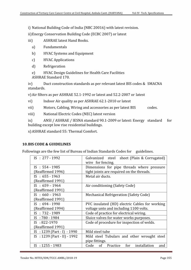
Construction of Tertiary Care Cancer Centre at Civil Hospital, Ambala Cantt. (HARYANA) Vol-IV- Tech. Specifications
Tender No. HITES/IDN/TCCC-AMBL/2018-19 Page 355
i) National Building Code of India (NBC 20016) with latest revision.
ii) Energy Conservation Building Code (ECBC 2007) or latest
iii) ASHRAE latest Hand Books.
a) Fundamentals
b) HVAC Systems and Equipment
c) HVAC Applications
d) Refrigeration
e) HVAC Design Guidelines for Health Care Facilities ASHRAE Standard 170.
iv) Duct construction standards as per relevant latest BIS codes & SMACNA standards.
v) Air filters as per ASHRAE 52.1-1992 or latest and 52.2-2007 or latest
vi) Indoor Air quality as per ASHRAE 62.1-2010 or latest
vii) Motors, Cabling, Wiring and accessories as per latest BIS codes.
viii) National Electric Codes (NEC) latest version
ix) ANSI / ASHRAE / IESNA standard 90.1-2009 or latest: Energy standard for building except low rise residential buildings.
x) ASHRAE standard 55: Thermal Comfort.
10. BIS CODE & GUIDELINES
Followings are the few list of Bureau of Indian Standards Codes for guidelines.
IS : 277 - 1992 Galvanized steel sheet (Plain & Corrugated) wire for fencing.
IS : 554 - 1985 (Reaffirmed 1996)
Dimensions for pipe threads where pressure tight joints are required on the threads.
IS : 655 - 1963 (Reaffirmed 1991)
Metal air ducts.
IS : 659 – 1964 (Reaffirmed 1991)
Air conditioning (Safety Code)
IS : 660 – 1963 (Reaffirmed 1991)
Mechanical Refrigeration (Safety Code)
IS : 694 - 1990 (Reaffirmed 1994)
PVC insulated (HD) electric Cables for working voltage unto and including 1100 volts.
IS : 732 - 1989 Code of practice for electrical wiring. IS : 780 - 1984 Sluice valves for water works purposes. IS : 822-1970 (Reaffirmed 1991)
Code of procedure for inspection of welds.
IS : 1239 (Part - I) - 1990 Mild steel tube IS : 1239 (Part - II) - 1992 Mild steel Tubulars and other wrought steel
pipe fittings. IS : 1255 - 1983 Code of Practice for installation and
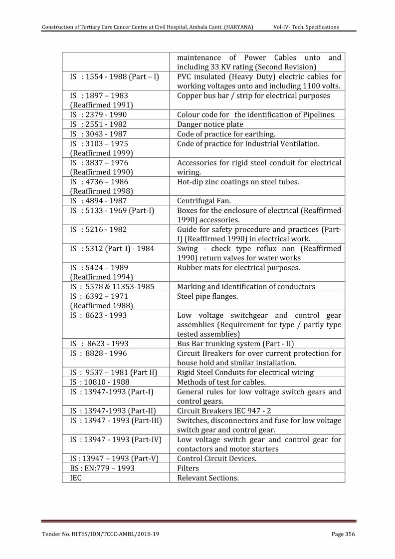
Construction of Tertiary Care Cancer Centre at Civil Hospital, Ambala Cantt. (HARYANA) Vol-IV- Tech. Specifications
Tender No. HITES/IDN/TCCC-AMBL/2018-19 Page 356
maintenance of Power Cables unto and including 33 KV rating (Second Revision)
IS : 1554 - 1988 (Part – I) PVC insulated (Heavy Duty) electric cables for working voltages unto and including 1100 volts.
IS : 1897 – 1983 (Reaffirmed 1991)
Copper bus bar / strip for electrical purposes
IS : 2379 - 1990 Colour code for the identification of Pipelines. IS : 2551 - 1982 Danger notice plate IS : 3043 - 1987 Code of practice for earthing. IS : 3103 – 1975 (Reaffirmed 1999)
Code of practice for Industrial Ventilation.
IS : 3837 – 1976 (Reaffirmed 1990)
Accessories for rigid steel conduit for electrical wiring.
IS : 4736 – 1986 (Reaffirmed 1998)
Hot-dip zinc coatings on steel tubes.
IS : 4894 - 1987 Centrifugal Fan. IS : 5133 - 1969 (Part-I) Boxes for the enclosure of electrical (Reaffirmed
1990) accessories. IS : 5216 - 1982 Guide for safety procedure and practices (Part-
I) (Reaffirmed 1990) in electrical work. IS : 5312 (Part-I) - 1984 Swing - check type reflux non (Reaffirmed
1990) return valves for water works IS : 5424 – 1989 (Reaffirmed 1994)
Rubber mats for electrical purposes.
IS : 5578 & 11353-1985 Marking and identification of conductors IS : 6392 – 1971 (Reaffirmed 1988)
Steel pipe flanges.
IS : 8623 - 1993 Low voltage switchgear and control gear assemblies (Requirement for type / partly type tested assemblies)
IS : 8623 - 1993 Bus Bar trunking system (Part - II) IS : 8828 - 1996 Circuit Breakers for over current protection for
house hold and similar installation. IS : 9537 – 1981 (Part II) Rigid Steel Conduits for electrical wiring IS : 10810 - 1988 Methods of test for cables. IS : 13947-1993 (Part-I) General rules for low voltage switch gears and
control gears. IS : 13947-1993 (Part-II) Circuit Breakers IEC 947 - 2 IS : 13947 - 1993 (Part-III) Switches, disconnectors and fuse for low voltage
switch gear and control gear. IS : 13947 - 1993 (Part-IV) Low voltage switch gear and control gear for
contactors and motor starters IS : 13947 – 1993 (Part-V) Control Circuit Devices. BS : EN:779 – 1993 Filters IEC Relevant Sections.

Construction of Tertiary Care Cancer Centre at Civil Hospital, Ambala Cantt. (HARYANA) Vol-IV- Tech. Specifications
Tender No. HITES/IDN/TCCC-AMBL/2018-19 Page 357
SPECIFICATIONS FOR HVAC ELECTRICAL PANELS/ CABLES/ CABLE TRAYS/ SWITCHGEARS ETC. SHALL BE AS PER ELECTRICAL SPECIFICATIONS GIVEN IN RESPECTIVE HEADS.
MODE OF MEASUREMENT
1 General
This specification covers measurement of various items/materials at site.
2 Unit Prices in the Schedule of Quantities
The item description in the Schedule of Quantities is in the form of a condensed resume. The unit price shall be held to include everything necessary to complete the work covered by this item in accordance with the specifications and drawings. The sum of all the individual item prices shall represent the total price of the installation ready to be handed over.
The unit price of the various items shall include the
All equipment, machinery, apparatus and materials required as well as the cost of any tests which the consultant may request in addition to the tests generally required to prove quality and performance of equipment.
All the labour required to supply and install the complete installation in accordance with the specifications.
Use of any tools, equipment, machinery, lifting tackle, scaffolding ladders etc. required by the contractor to carry out his work.
All the necessary measures to prevent the transmission of vibration.
The necessary material to isolate equipment foundations, from the building structure, wherever necessary and suggested by the Engineer.
Storage and insurance of all equipment apparatus and materials.
The Contractor's unit price shall include all equipment, apparatus material and labour indicated in the drawings and/or specifications in conjunction with the item in question, as well as all additional equipment, apparatus, material and labour usual and necessary to complete the system even though not specifically shown, described or otherwise referred to.
Construction of Tertiary Care Cancer Centre at Civil Hospital, Ambala Cantt. (HARYANA) Vol-IV- Tech. Specifications
Tender No. HITES/IDN/TCCC-AMBL/2018-19 Page 358
3 Measurements of Sheet metal ducts, grilles/diffusers, etc.
a) Sheet Metal Ducts
All duct measurements shall be taken as per actual outer duct surface area including bends, tees, reducers, collars and other fittings. Gaskets, nuts, bolts vibration isolation pads, vanes are included in the basic duct items of the B.O.Q.
The unit of measurements shall be the finished sheet metal surface area in metre squares. No extra shall be allowed for overlaps.
All the guide vanes, deflectors access panels, splitter dampers within the duct work shall be considered as part of the duct and nothing will be paid extra on this account.
The unit duct price shall include all the duct hangers, supports and metallic fasteners as well as any materials and labour required to complete the duct frame.
b) Box Dampers
Box dampers wherever shown or required in ducts shall be measured as per finished inside cross-sections and paid as per the calculated are in sq.m.
c) Grilles/Diffusers
All measurements of grilles/diffusers shall be the nominal outlet size excluding the outer flanges.
The square or rectangular grilles/diffusers shall be measured in plain sq.m.
All round diffusers shall be measured by their diameters in centimetre.
All linear diffusers shall be measured as per actual length in meters.
4 Measurements of Piping, Fittings, Valves, Fabricated Items
a) Pipe
Construction of Tertiary Care Cancer Centre at Civil Hospital, Ambala Cantt. (HARYANA) Vol-IV- Tech. Specifications
Tender No. HITES/IDN/TCCC-AMBL/2018-19 Page 359
(Including Water Piping, Oil Piping, L.P. Gas Piping, Air Piping, Vacuum Piping, etc.)
All pipes shall be measured in linear meter (to the nearest Cm.) along the axis of the pipes and rates shall be inclusive of all fittings e.g. tees, bends, reducer, elbows, hanger support bracket, etc. Deduction shall be made for valves in the line.
The rate quoted shall be inclusive of cutting holes, metallic fasteners and inclusive of all items as specified in specifications and Schedule of Quantities.
Rates quoted shall be inclusive of providing and fixing vibration pads and wooden pieces, wherever specified or required by the Engineer-in-Charge.
Flexible connections, wherever required or specified shall be measured as part of straight length of same diameter, with no additional allowances being made for providing the same.
The length of the pipe for the purpose of payment will be taken through the centre line of the pipe and all fittings (e.g. tees, bends, reducers, elbows, etc.) as through the fittings are also presumed to be pipe lengths. Nothing extra whatsoever will be paid for over and above the fittings. For valves and flanges, section 1.16.3.2 below applies:
b) Valves and Flanges
All the C.I. and G.M. valves shall be measured according to the nominal size in mm and shall be measured by number. Such valves shall not be counted as part of pipe length hence deduction in pipe length, will be made wherever valves occur.
All gate and globe valves shall include two nos. of flanges and two numbers 150 mm long M.S. nipples, with one side threaded matching one of the valves, and other welded to the M.S. slip-on- flanges.
Rate for all valves shall also include the necessary number of bolts, nuts and washers, 3mm thick insertion gasket of required temperature grade companion flanges and all items specified in the specification.
The rates quoted shall be inclusive of making connections to the equipment, tanks, pumps, etc. and the connection made with an installed pipe line shall be included in the rates as per the B.O.Q.
Construction of Tertiary Care Cancer Centre at Civil Hospital, Ambala Cantt. (HARYANA) Vol-IV- Tech. Specifications
Tender No. HITES/IDN/TCCC-AMBL/2018-19 Page 360
c) Structural Supports
Structural supports including supports fabricated from pipe lengths for pipes shall be measured as part of pipe line and hence no separate payment will be made. Rates shall be inclusive of hoisting, cutting, jointing, welding, cutting of holes and chases in walls, slabs or floors, painting supports and other items as described in specifications, drawings and schedule of quantities or as required at site by Engineer-in-Charge.
d) Copper Connections for Fan Coil Units
Copper connection assembly for making connections to the fan coil units shall be measured, as part of the fan coil unit price and shall include brass flare nuts, brass tees, brass reducers, fittings, fixing of automatic 3 way valve, making connections and leak testing, complete assembly as per specifications and drawings. Nothing extra shall be payable on account of any variation in the length of copper pipe.
5 Painting
Painting of all pipes, supports, valves and fittings shall be included with the cost of these items. Nothing extra shall be paid for this work.
Painting of grilles/diffusers, tanks and equipment wherever required shall be in the cost of these items.
6 Insulation
Measurement of insulation for vessels, piping, equipment and ducts shall be made over the bare uninsulated surface area of the metal.
a) Pipes
The measurements for insulation of piping shall be made in linear meters through all valves, flanges, and fittings. Pipes/bends shall be measured along the centre line radius between tangent points. If the outer radius is R1 and the inner radius is R2, the centre line radius shall be measured as (R1+R2)/2. Measurement of all valves, flanges and fittings shall be taken in running metre of pipe line as if they are also pipe lengths. Nothing extra over the above shall be payable for insulation over valves, flanges and fittings in pipe line/routings. Fittings that connect two or more different sizes of pipe shall be measured as part of the larger size.
Construction of Tertiary Care Cancer Centre at Civil Hospital, Ambala Cantt. (HARYANA) Vol-IV- Tech. Specifications
Tender No. HITES/IDN/TCCC-AMBL/2018-19 Page 361
b) Ducts
The measurements for insulation of ducts shall be made in actual square meters of bare uninsulated duct surface.
In case of bends the area shall be worked out by taking an average of inner and outer lengths of the bends. Measure-ments for damper, flanges, fittings shall be for the surface dimension for the connecting duct. Nothing extra over the above shall be payable for insulation over dampers, flanges and fittings in duct routing.
c) Vessels
The area of standard dished and flat ends of vessels shall be measured as the uninsulated body of the shell. Areas for other shapes shall be the actual calculated area. There shall be no deduction or additions for nozzles, handle ribs, dampers, expansion joints etc. all projections on vessels or tanks shall be measured separately as pipe/duct.
d) Accessories Insulation
The unit of measurement for accessories such as expansion tank, pumps, chiller heads etc. shall be of uninsulated area in square meters. In case of curved or irregular surfaces, measurements shall be taken along the curves. The unit insulation price shall include all necessary adhesives, vapour proofing and finishing materials as well as additional labour and material required for fixing the insulation.
e) Acoustic Duct Lining
In case of acoustic lining of air ducts, measurements of the bare inside duct surface in square metre, shall be final for billing purpose.
The insulation/acoustic treatment shall include cost of battens/sections, supports, adhesives, vapour proofing, finished tiles/boards/sheets as well as additional labour and materials required for completing the work.
f) Roof and Wall Insulation and Acoustic Treatment
The unit of measurement for all underdeck roof insulation wall insulation, wall/roof acoustic panel shall be the acoustic uninsulated area of walls, roofs, to be treated, in square metres.
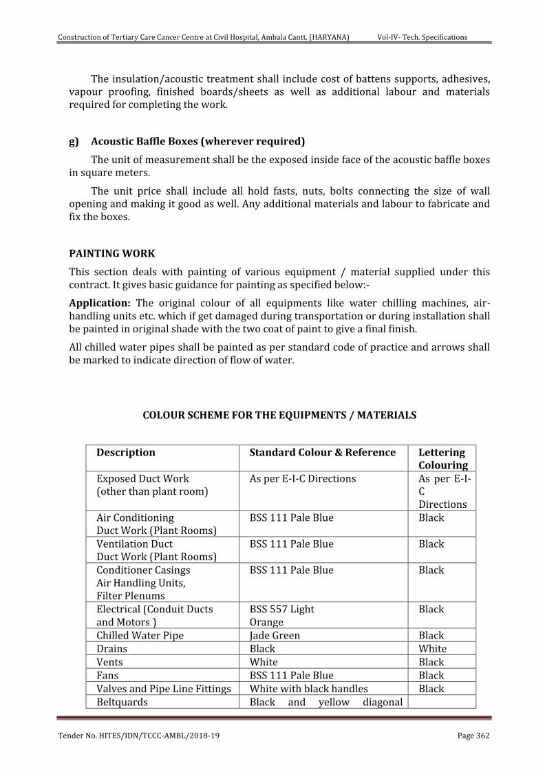
Construction of Tertiary Care Cancer Centre at Civil Hospital, Ambala Cantt. (HARYANA) Vol-IV- Tech. Specifications
Tender No. HITES/IDN/TCCC-AMBL/2018-19 Page 362
The insulation/acoustic treatment shall include cost of battens supports, adhesives, vapour proofing, finished boards/sheets as well as additional labour and materials required for completing the work.
g) Acoustic Baffle Boxes (wherever required)
The unit of measurement shall be the exposed inside face of the acoustic baffle boxes in square meters.
The unit price shall include all hold fasts, nuts, bolts connecting the size of wall opening and making it good as well. Any additional materials and labour to fabricate and fix the boxes.
PAINTING WORK
This section deals with painting of various equipment / material supplied under this contract. It gives basic guidance for painting as specified below:-
Application: The original colour of all equipments like water chilling machines, air-handling units etc. which if get damaged during transportation or during installation shall be painted in original shade with the two coat of paint to give a final finish.
All chilled water pipes shall be painted as per standard code of practice and arrows shall be marked to indicate direction of flow of water.
COLOUR SCHEME FOR THE EQUIPMENTS / MATERIALS
Description Standard Colour & Reference Lettering Colouring
Exposed Duct Work (other than plant room)
As per E-I-C Directions As per E-I-C Directions
Air Conditioning Duct Work (Plant Rooms)
BSS 111 Pale Blue Black
Ventilation Duct Duct Work (Plant Rooms)
BSS 111 Pale Blue Black
Conditioner Casings Air Handling Units, Filter Plenums
BSS 111 Pale Blue Black
Electrical (Conduit Ducts and Motors )
BSS 557 Light Orange
Black
Chilled Water Pipe Jade Green Black Drains Black White Vents White Black Fans BSS 111 Pale Blue Black Valves and Pipe Line Fittings White with black handles Black Beltquards Black and yellow diagonal
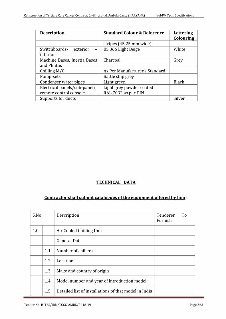
Construction of Tertiary Care Cancer Centre at Civil Hospital, Ambala Cantt. (HARYANA) Vol-IV- Tech. Specifications
Tender No. HITES/IDN/TCCC-AMBL/2018-19 Page 363
Description Standard Colour & Reference Lettering Colouring
stripes (45 25 mm wide) Switchboards- exterior – interior
BS 366 Light Beige White
Machine Bases, Inertia Bases and Plinths
Charcoal Grey
Chilling M/C As Per Manufacturer’s Standard Pump-sets Battle ship grey Condenser water pipes Light green Black Electrical panels/sub-panel/ remote control console
Light grey powder coated RAL 7032 as per DIN
Supports for ducts Silver
TECHNICAL DATA
Contractor shall submit catalogues of the equipment offered by him :
S.No Description Tenderer To Furnish
1.0 Air Cooled Chilling Unit
General Data
1.1 Number of chillers
1.2 Location
1.3 Make and country of origin
1.4 Model number and year of introduction model
1.5 Detailed list of installations of that model in India
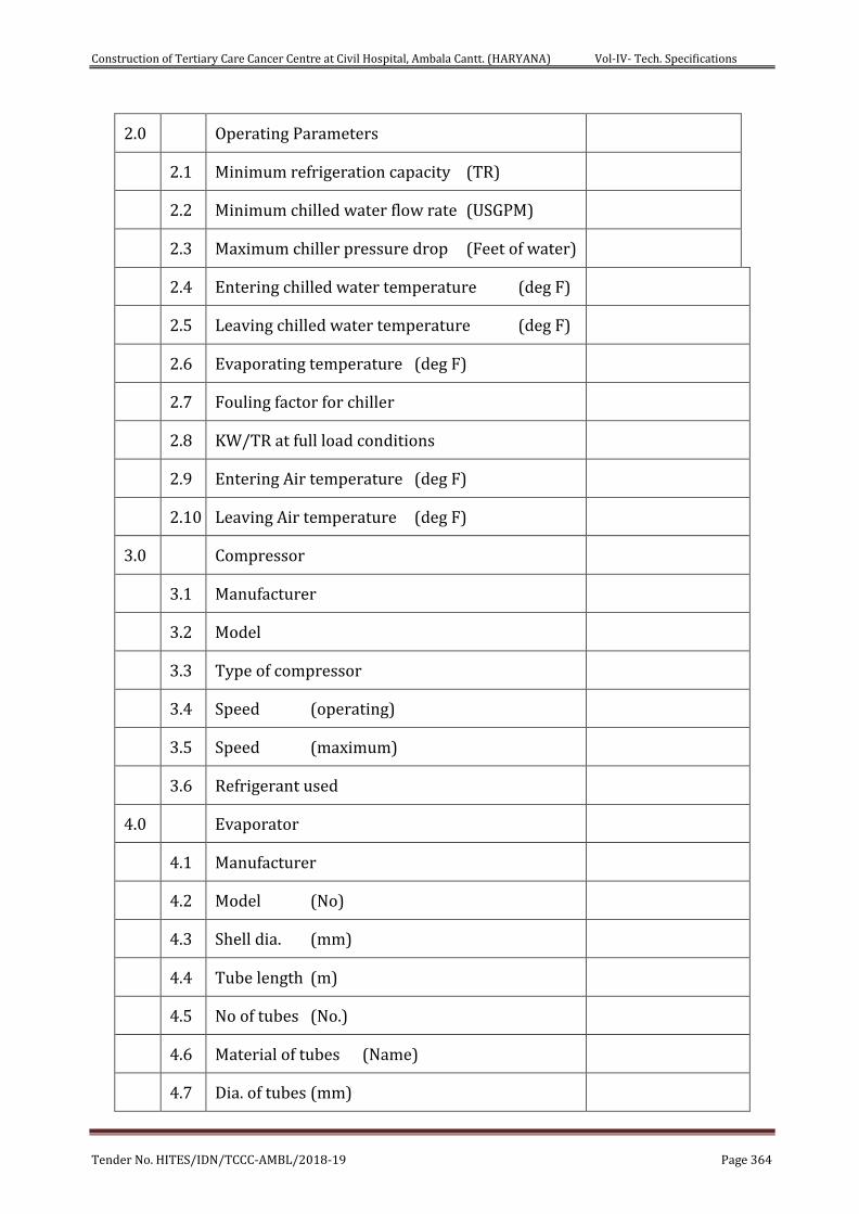
Construction of Tertiary Care Cancer Centre at Civil Hospital, Ambala Cantt. (HARYANA) Vol-IV- Tech. Specifications
Tender No. HITES/IDN/TCCC-AMBL/2018-19 Page 364
2.0 Operating Parameters
2.1 Minimum refrigeration capacity (TR)
2.2 Minimum chilled water flow rate (USGPM)
2.3 Maximum chiller pressure drop (Feet of water)
2.4 Entering chilled water temperature (deg F)
2.5 Leaving chilled water temperature (deg F)
2.6 Evaporating temperature (deg F)
2.7 Fouling factor for chiller
2.8 KW/TR at full load conditions
2.9 Entering Air temperature (deg F)
2.10 Leaving Air temperature (deg F)
3.0 Compressor
3.1 Manufacturer
3.2 Model
3.3 Type of compressor
3.4 Speed (operating)
3.5 Speed (maximum)
3.6 Refrigerant used
4.0 Evaporator
4.1 Manufacturer
4.2 Model (No)
4.3 Shell dia. (mm)
4.4 Tube length (m)
4.5 No of tubes (No.)
4.6 Material of tubes (Name)
4.7 Dia. of tubes (mm)
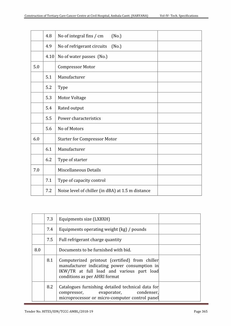
Construction of Tertiary Care Cancer Centre at Civil Hospital, Ambala Cantt. (HARYANA) Vol-IV- Tech. Specifications
Tender No. HITES/IDN/TCCC-AMBL/2018-19 Page 365
4.8 No of integral fins / cm (No.)
4.9 No of refrigerant circuits (No.)
4.10 No of water passes (No.)
5.0 Compressor Motor
5.1 Manufacturer
5.2 Type
5.3 Motor Voltage
5.4 Rated output
5.5 Power characteristics
5.6 No of Motors
6.0 Starter for Compressor Motor
6.1 Manufacturer
6.2 Type of starter
7.0 Miscellaneous Details
7.1 Type of capacity control
7.2 Noise level of chiller (in dBA) at 1.5 m distance
7.3 Equipments size (LXBXH)
7.4 Equipments operating weight (kg) / pounds
7.5 Full refrigerant charge quantity
8.0 Documents to be furnished with bid.
8.1 Computerized printout (certified) from chiller manufacturer indicating power consumption in IKW/TR at full load and various part load conditions as per AHRI format
8.2 Catalogues furnishing detailed technical data for compressor, evaporator, condenser, microprocessor or micro-computer control panel
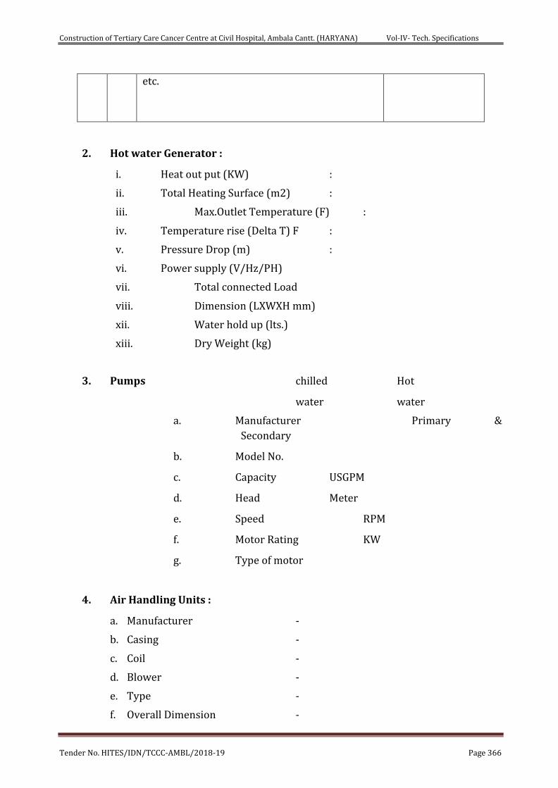
Construction of Tertiary Care Cancer Centre at Civil Hospital, Ambala Cantt. (HARYANA) Vol-IV- Tech. Specifications
Tender No. HITES/IDN/TCCC-AMBL/2018-19 Page 366
etc.
2. Hot water Generator :
i. Heat out put (KW) :
ii. Total Heating Surface (m2) :
iii. Max.Outlet Temperature (F) :
iv. Temperature rise (Delta T) F :
v. Pressure Drop (m) :
vi. Power supply (V/Hz/PH)
vii. Total connected Load
viii. Dimension (LXWXH mm)
xii. Water hold up (lts.)
xiii. Dry Weight (kg)
3. Pumps chilled Hot
water water
a. Manufacturer Primary &
Secondary
b. Model No.
c. Capacity USGPM
d. Head Meter
e. Speed RPM
f. Motor Rating KW
g. Type of motor
4. Air Handling Units :
a. Manufacturer -
b. Casing -
c. Coil -
d. Blower -
e. Type -
f. Overall Dimension -
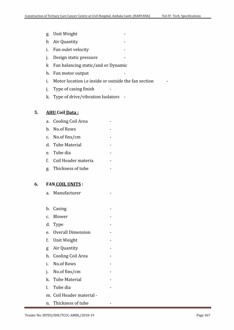
Construction of Tertiary Care Cancer Centre at Civil Hospital, Ambala Cantt. (HARYANA) Vol-IV- Tech. Specifications
Tender No. HITES/IDN/TCCC-AMBL/2018-19 Page 367
g. Unit Weight -
h Air Quantity -
i. Fan oulet velocity -
j. Design static pressure -
k Fan balancing static/and or Dynamic
h. Fan motor output -
i. Motor location i.e inside or outside the fan section -
j. Type of casing finish -
k. Type of drive/vibration Isolators -
5. AHU Coil Data :
a. Cooling Coil Area -
b. No.of Rows -
c. No.of fins/cm -
d. Tube Material -
e. Tube dia -
f. Coil Header materia -
g. Thickness of tube -
6. FAN COIL UNITS :
a. Manufacturer -
b. Casing -
c. Blower -
d. Type -
e. Overall Dimension -
f. Unit Weight -
g Air Quantity -
h. Cooling Coil Area -
i. No.of Rows -
j. No.of fins/cm -
k. Tube Material -
l. Tube dia -
m. Coil Header material -
n. Thickness of tube -
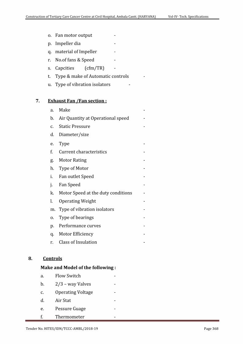
Construction of Tertiary Care Cancer Centre at Civil Hospital, Ambala Cantt. (HARYANA) Vol-IV- Tech. Specifications
Tender No. HITES/IDN/TCCC-AMBL/2018-19 Page 368
o. Fan motor output -
p. Impeller dia -
q. material of Impeller -
r. No.of fans & Speed -
s. Capcities (cfm/TR) -
t. Type & make of Automatic controls -
u. Type of vibration isolators -
7. Exhaust Fan /Fan section :
a. Make -
b. Air Quantity at Operational speed -
c. Static Pressure -
d. Diameter/size
e. Type -
f. Current characteristics -
g. Motor Rating -
h. Type of Motor -
i. Fan outlet Speed -
j. Fan Speed -
k. Motor Speed at the duty conditions -
l. Operating Weight -
m. Type of vibration isolators -
o. Type of bearings -
p. Performance curves -
q. Motor Efficiency -
r. Class of Insulation -
8. Controls
Make and Model of the following :
a. Flow Switch -
b. 2/3 – way Valves -
c. Operating Voltage -
d. Air Stat -
e. Pessure Guage -
f. Thermometer -
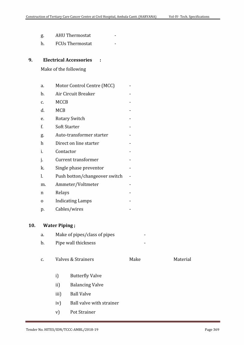
Construction of Tertiary Care Cancer Centre at Civil Hospital, Ambala Cantt. (HARYANA) Vol-IV- Tech. Specifications
Tender No. HITES/IDN/TCCC-AMBL/2018-19 Page 369
g. AHU Thermostat -
h. FCUs Thermostat -
9. Electrical Accessories :
Make of the following
a. Motor Control Centre (MCC) -
b. Air Circuit Breaker -
c. MCCB -
d. MCB -
e. Rotary Switch -
f. Soft Starter -
g. Auto-transformer starter -
h Direct on line starter -
i. Contactor -
j. Current transformer -
k. Single phase preventor -
l. Push botton/changeover switch -
m. Ammeter/Voltmeter -
n Relays -
o Indicating Lamps -
p. Cables/wires -
10. Water Piping ;
a. Make of pipes/class of pipes -
b. Pipe wall thickness -
c. Valves & Strainers Make Material
i) Butterfly Valve
ii) Balancing Valve
iii) Ball Valve
iv) Ball valve with strainer
v) Pot Strainer
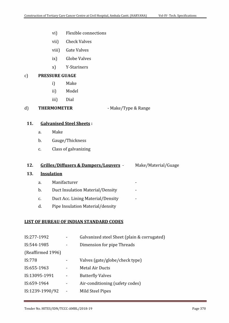
Construction of Tertiary Care Cancer Centre at Civil Hospital, Ambala Cantt. (HARYANA) Vol-IV- Tech. Specifications
Tender No. HITES/IDN/TCCC-AMBL/2018-19 Page 370
vi) Flexible connections
vii) Check Valves
viii) Gate Valves
ix) Globe Valves
x) Y-Stariners
c) PRESSURE GUAGE
i) Make
ii) Model
iii) Dial
d) THERMOMETER - Make/Type & Range
11. Galvanised Steel Sheets :
a. Make
b. Gauge/Thickness
c. Class of galvanizing
12. Grilles/Diffusers & Dampers/Louvers - Make/Material/Guage
13. Insulation
a. Manifacturer -
b. Duct Insulation Material/Density -
c. Duct Acc. Lining Material/Density -
d. Pipe Insulation Material/density
LIST OF BUREAU OF INDIAN STANDARD CODES
IS:277-1992 - Galvanized steel Sheet (plain & corrugated)
IS:544-1985 - Dimension for pipe Threads
(Reaffirmed 1996)
IS:778 - Valves (gate/globe/check type)
IS:655-1963 - Metal Air Ducts
IS:13095-1991 - Butterfly Valves
IS:659-1964 - Air-conditioning (safety codes)
IS:1239-1990/92 - Mild Steel Pipes
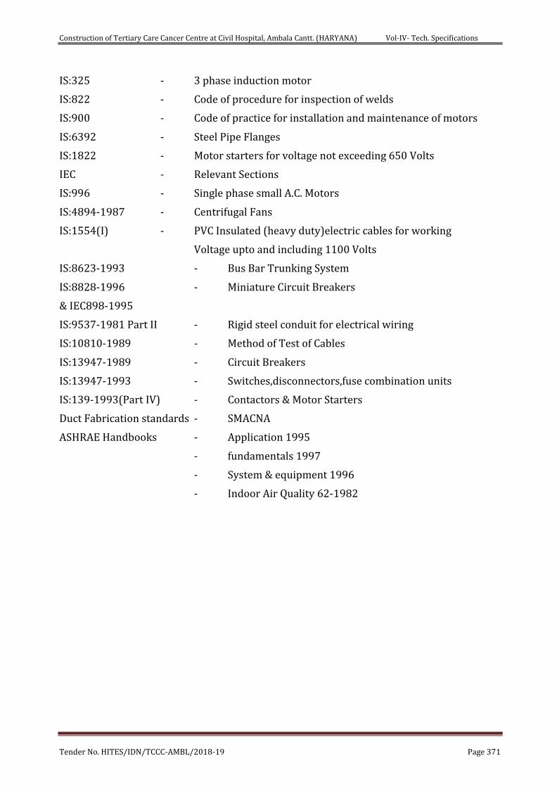
Construction of Tertiary Care Cancer Centre at Civil Hospital, Ambala Cantt. (HARYANA) Vol-IV- Tech. Specifications
Tender No. HITES/IDN/TCCC-AMBL/2018-19 Page 371
IS:325 - 3 phase induction motor
IS:822 - Code of procedure for inspection of welds
IS:900 - Code of practice for installation and maintenance of motors
IS:6392 - Steel Pipe Flanges
IS:1822 - Motor starters for voltage not exceeding 650 Volts
IEC - Relevant Sections
IS:996 - Single phase small A.C. Motors
IS:4894-1987 - Centrifugal Fans
IS:1554(I) - PVC Insulated (heavy duty)electric cables for working
Voltage upto and including 1100 Volts
IS:8623-1993 - Bus Bar Trunking System
IS:8828-1996 - Miniature Circuit Breakers
& IEC898-1995
IS:9537-1981 Part II - Rigid steel conduit for electrical wiring
IS:10810-1989 - Method of Test of Cables
IS:13947-1989 - Circuit Breakers
IS:13947-1993 - Switches,disconnectors,fuse combination units
IS:139-1993(Part IV) - Contactors & Motor Starters
Duct Fabrication standards - SMACNA
ASHRAE Handbooks - Application 1995
- fundamentals 1997
- System & equipment 1996
- Indoor Air Quality 62-1982
Construction of Tertiary Care Cancer Centre at Civil Hospital, Ambala Cantt. (HARYANA) Vol-IV- Tech. Specifications
Tender No. HITES/IDN/TCCC-AMBL/2018-19 Page 372
CHAPTER- 16
TECHNICAL SPECIFICATIONS- FIRE FIGHTING SYSTEM
1. FIRE FIGHTING WORKS- FIRE PROTECTIONS
Scope of work shall include design, engineering, supply, installation, testing & commissioning of firefighting system.
All material shall be of conforming to relevant IS specifications wherever exists and subject to approval of Engineer in charge.
The firefighting shall be carried out strictly as per NBC -2016.
Testing, commissioning & getting approvals from various inspection authorities and obtaining No objection certificate (NOC) for occupation of buildings.
1.1. TENDER DRAWINGS
For guidance of the bidder, drawings (Internal Fire Fighting Layout/External Fire Layout, etc.) are enclosed with these tender documents. These drawings are broadly indicative of the work to be carried out. The contractor on award of work will furnish detailed stage-wise working drawings as required in advance for approval of Engineer and get the same approved by Local Fire Authority/other statutory bodies. No claim whatsoever shall be admissible on account of changes that may be introduced by the Engineer/ Local Fire Authority.
1.2. SHOP DRAWINGS/TECHNICAL DATA SHEETS
The contractor shall prepare and furnish all shop drawings including floor plans & Terrace, Schematic Fire Fighting Layout/External Fire Layout showing sprinklers, Fire Hydrants/First Aid Hose, Zonal Control Valves, Extinguishers, Signage’s, Terrace layout with OHT.
Such shop drawings shall be based on the Architectural drawings/Tender Drawings and requirements laid down in the Specifications, BOQ and as per site conditions. The manufacturing of equipment shall be commenced only after the shop drawings/GA Drawings/ technical data sheet along with pump curves are approved in writing by the Engineer. Such drawings shall be coordinated with other services work. These shop drawings will be approved by HITES which will be considered as base for execution of fire fighting work.
1.3. COMPLETION / AS BUILT DRAWINGS
On completion of the work and before issuance of certificate of virtual completion, the contractor shall submit to the Engineer –in-Charge, General Layout drawings, drawn at approved scale indicating layout of all Firefighting items, piping and its accessories “As installed”. As built drawings shall be prepared taking approved shop drawings as base & incorporating all changes/ modifications as per site conditions. These drawings shall include the following:-
a. Firefighting floor layout including terrace indicating internal hydrants, sprinklers complete
with pipe dia. , pipe spacing interval etc.
Construction of Tertiary Care Cancer Centre at Civil Hospital, Ambala Cantt. (HARYANA) Vol-IV- Tech. Specifications
Tender No. HITES/IDN/TCCC-AMBL/2018-19 Page 373
b. Complete schematic as installed.
c. UG Sumps, Location of External Hydrants, Fire Hose Cabinet, 2-way/4-way fire brigade inlet
connection, Draw out connection, Fire Extinguishers, Earth pipes, route of earthling
conductors etc.
d. Route of all cables and pipes run along with size details and mode of installation.
e. General Layout of Pump House including all details mentioned in clause 1.2.
f. Panels and other equipment/accessories location and their dimensions etc.
1.4. DRAWINGS & DOCUMENTS
The contractor shall submit to the Engineer, the following documents on completion of the work and before issuance of virtual completion.
a. Warranty for required equipment installed
b. As Built Drawings
c. Material Test Certificates
d. Catalogues/Brochures
e. Operation and Maintenance Manuals
f. List of recommended spares and consumables
g. All approvals including technical approvals and sanctions
h. NOC from Fire authority before commencement of execution & after completion of
entire work etc.
1.5. SANCTION/ APPROVALS FROM STATUTORY AUTHORITIES/ LOCAL FIRE
AUTHORITY
The contractor shall be fully responsible and shall carry out following activities:-
a. Preparation & submission of working drawings
b. Obtaining the approval of drawings
c. Arranging inspection of site by officials of the Authority
d. Obtaining the final No objection/ completion certificate after submitting
required documents.
e. Any other statutory approvals required.
1.6. MANUFACTURING
The responsibility for ensuring the manufacture of the equipment as per the specifications shall be solely that of the contractor. The contractor shall be responsible for selection of materials as per agreed specifications and BOQ.
1.7. MAKE OF MATRIALS/MANUFACTURER’S INSTRUCTION
Only approved makes as mentioned in our approved make list of tender documents of material shall be used. The Contractor shall furnish Technical data sheets / GA drawings of all items before placing P.O. The contractor shall get the samples of required items approved from the HITES as conveyed by E-I-C before commencing the supply. In case of any discrepancy/anomalies wrt specifications, prior
Construction of Tertiary Care Cancer Centre at Civil Hospital, Ambala Cantt. (HARYANA) Vol-IV- Tech. Specifications
Tender No. HITES/IDN/TCCC-AMBL/2018-19 Page 374
intimation from Contractor to E-I-C to be given. Final decision lies with HITES for according approvals.
Any specific instruction furnished by manufacturer covering the points not mentioned in technical specifications of the tender shall be brought to the notice of E-I-C in writing for further instructions in this regard at appropriate time.
MATERIAL TESTING
The E-I-C shall have full power to get any material of work to be tested by an independent agency at contractor’s expense in order to prove the soundness and adequacy.
1.8. INSPECTION AND TESTING
a. All equipment shall be inspected and tested as per an agreed Quality
Assurance Plan before the same is packed and dispatched from the
contractor’s works. The contractor shall carry out tests as specified/
directed by engineer.
b. Contractor shall perform all such tests as may be necessary to meet
requirements of Local Authorities, Municipal or other statutory laws/ bye-
laws in force. Nothing extra shall be paid for these.
c. The E-I-C may, at his sole discretion, carry out inspection at different stages
during manufacturing and final testing after manufacturing.
d. Approvals or passing of any inspection by the engineer or his authorized
representative shall not, however, prejudice the right of the engineer to
reject the plan if it does not comply with the specification when erected or
give complete satisfaction in service.
1.9. TRAINING OF DEPARTMENT PERSONNEL
a. The contractor shall train the CLIENT/ HITES’s personnel to become proficient in operating the
equipment installed. Training shall be done before the expiry of the defects liability period (one
year after completion & handing over).
b. The period of training shall be adequate and mutually agreed upon by the Engineer and
contractor.
c. The CLIENT/ HITES’s personnel shall also be trained for routine maintenance work and
lubrication, overhauling, adjustments, testing, minor repairs and replacement.
d. Nothing extra shall be paid to the contractor for training CLIENT/ HITES’s personnel.
1.10. PERFORMANCE GUARANTEE
At the close of the work and before issue of final certificate of virtual completion by the engineer, the contractor shall furnish written guarantee indemnifying the CLIENT/ HITES against defective materials and workmanship for a period of one year after completion and handing over. The contractor shall hold himself fully responsible for reinstallation or replace free of cost to the CLIENT/ HITES.
a. Any defective material or equipment supplied by the contractor.
Construction of Tertiary Care Cancer Centre at Civil Hospital, Ambala Cantt. (HARYANA) Vol-IV- Tech. Specifications
Tender No. HITES/IDN/TCCC-AMBL/2018-19 Page 375
b. Any material or equipment supplied by the CLIENT/ HITES which is proved
to be damaged or destroyed as a result of defective workmanship by the
contractor.
2. PIPING FOR WET RISER SYSTEM
2.1. SCOPE
This section covers the details of requirement of piping used in wet riser system, including the associated auxiliary equipment.
2.2. GENERAL
The wet riser system shall remain pressurized at all times during operation, and as such the piping work shall be carried out to withstand the same.
2.3. PIPES AND FITTINGS
Pipes and fittings means tees, elbows, couplings, flanges, reducers etc. and all such connecting devices that are needed to complete the piping work in its totality.
Screwed fittings shall be approved type malleable or cast iron with reinforced ring on all edges of the fittings suitable for screwed joints.
Forged steel fittings of approved type with "V" groove for welded joints.
Fabricated fittings shall be not being permitted for pipe diameters 50 mm and below. When used, they shall be fabricated, welded and inspected in workshops whose welding procedures have been approved by the TAC as per TAC rule 4102 for sprinkler system and applicable to hydrant and sprinkler System under the supervision of Engineer-In-Charge. For "T" connections, pipes shall be drilled and reamed. Cutting by gas or electrical welding will not be accepted.
Pipes for Wet Riser system shall be of black steel MS conforming to IS: 1239/3589 (Heavy Class/ Class C).
Fittings for black steel pipes shall be malleable iron suitable for welding or tapered screwed threads.
2.4. JOINTING
2.4.1. Screwed (50 mm dia pipes and below)
Joint for black steel pipes and fittings shall be metal to metal thread joints. A small amount of red lead may be used for lubrication and rust prevention. Joints shall not be welded or caulked.
2.4.2. Welded (65 mm dia and above)
Joints between M.S. pipes and fittings shall be made with the pipes and fittings having "V" groove and welded with electrical resistance welding in an approved manner. Butt welded joints are not acceptable.
2.4.3. Flanged
Flanged joints shall be provided on:
a. Straight runs not exceeding 30 m on pipe lines 80 mm dia and above.
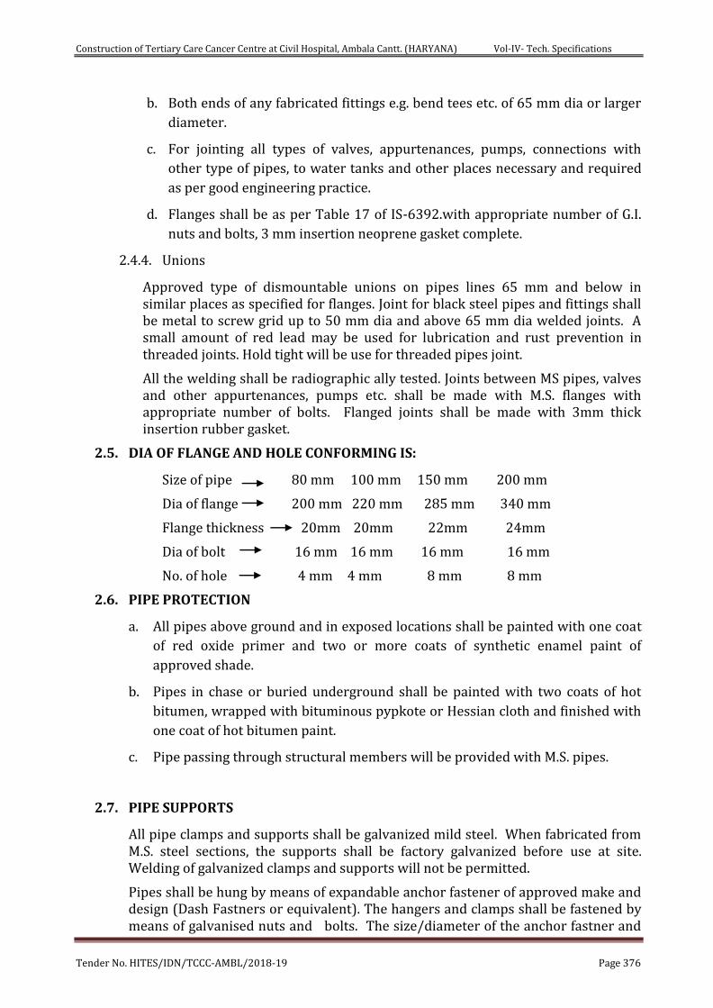
Construction of Tertiary Care Cancer Centre at Civil Hospital, Ambala Cantt. (HARYANA) Vol-IV- Tech. Specifications
Tender No. HITES/IDN/TCCC-AMBL/2018-19 Page 376
b. Both ends of any fabricated fittings e.g. bend tees etc. of 65 mm dia or larger
diameter.
c. For jointing all types of valves, appurtenances, pumps, connections with
other type of pipes, to water tanks and other places necessary and required
as per good engineering practice.
d. Flanges shall be as per Table 17 of IS-6392.with appropriate number of G.I.
nuts and bolts, 3 mm insertion neoprene gasket complete.
2.4.4. Unions
Approved type of dismountable unions on pipes lines 65 mm and below in similar places as specified for flanges. Joint for black steel pipes and fittings shall be metal to screw grid up to 50 mm dia and above 65 mm dia welded joints. A small amount of red lead may be used for lubrication and rust prevention in threaded joints. Hold tight will be use for threaded pipes joint.
All the welding shall be radiographic ally tested. Joints between MS pipes, valves and other appurtenances, pumps etc. shall be made with M.S. flanges with appropriate number of bolts. Flanged joints shall be made with 3mm thick insertion rubber gasket.
2.5. DIA OF FLANGE AND HOLE CONFORMING IS:
Size of pipe 80 mm 100 mm 150 mm 200 mm
Dia of flange 200 mm 220 mm 285 mm 340 mm
Flange thickness 20mm 20mm 22mm 24mm
Dia of bolt 16 mm 16 mm 16 mm 16 mm
No. of hole 4 mm 4 mm 8 mm 8 mm
2.6. PIPE PROTECTION
a. All pipes above ground and in exposed locations shall be painted with one coat
of red oxide primer and two or more coats of synthetic enamel paint of
approved shade.
b. Pipes in chase or buried underground shall be painted with two coats of hot
bitumen, wrapped with bituminous pypkote or Hessian cloth and finished with
one coat of hot bitumen paint.
c. Pipe passing through structural members will be provided with M.S. pipes.
2.7. PIPE SUPPORTS
All pipe clamps and supports shall be galvanized mild steel. When fabricated from M.S. steel sections, the supports shall be factory galvanized before use at site. Welding of galvanized clamps and supports will not be permitted.
Pipes shall be hung by means of expandable anchor fastener of approved make and design (Dash Fastners or equivalent). The hangers and clamps shall be fastened by means of galvanised nuts and bolts. The size/diameter of the anchor fastner and
Construction of Tertiary Care Cancer Centre at Civil Hospital, Ambala Cantt. (HARYANA) Vol-IV- Tech. Specifications
Tender No. HITES/IDN/TCCC-AMBL/2018-19 Page 377
the clamp shall be suitable to carry the weight of water filled pipe and dead load normally encounted. For pipe spacing, the stringent of the IS Code- clause no. 10.3.10, table -11 & below mentioned table should be opted.
2.8. ORIFICE PLATES
Contractor shall provide orifice flanges fabricated from 6 mm thick SS plates on the branch lines feeding different zones/ floors (as required) so as to allow required flow of water at 3.5 Kg/ sq.cm. Pressure. The contractor shall furnish design for these orifice flanges. The orifice shall be plain central hole without burs, diameter not less than half of the internal diameter of pipe to which it is fitted.
2.9. AIR CUSHION TANK AND AIR RELEASE VALVE
Air vessel on top of each wet riser/ sprinkler piping shall be installed before execution for approval fabricated out of at least 8 mm thick steel to withstand the pressure, with dished ends and supporting legs. This shall be of 250 mm dia and 200mm high. This shall be completed with necessary flange connection to the wet riser/ sprinkler piping and air release valve with necessary piping to meet the functional requirement of the system. The air vessel shall be of continuous welded construction and painted with Red Color. This shall be tested for twice the working pressure. The drain arrangement will have 25mm dia GM valve with required accessories and pressure gauge. ARV shall be of 25 mm of forged brass body & chrome plated & its components shall be of anticorrosive material. Test Pressure (Hydrostatic) for Shell: 15 bar (220 psig), Seat: 10 bar (150 psig) & Maximum Working Temperature: 110 degree C.
2.10. VALVES, GAUGES
Butter-fly, Sluice valves and NRV above 65 mm shall be of cast iron body .They shall conform to type PN 16 of IS: 13095,780. Valve wheels shall be of right hand type and have an arrowhead engraved or cast thereon the direction for turning open and closing.
Butterfly valves of various dia. as per requirements shall be of wafer type, conforming to PN-16 rating with SS disc. It shall be lever operated. The rubber lining shall be integrally moulded with EPDM/Nitrile rubber. The O-ring sall be made of nitrile rubber. The lever shall be made preferably of carbon steel.
The test pressure of Shell- 24 Bar, Seat:17.6 bar & maximum working pressure-16 bar, maximum working temperature :90 degree celcius. In case of any discrepencies between manufacturer’s standards & above specified values, these parameters shall be in compliance with relevant IS codes.
Non-return valves/ Dual plate check valve of various dia. as per requirements shall be of cast iron body. It should have Nitrile Rubber/EPDM Seal & Disc of stainless steel. They shall be swing check type/wafer type in horizontal runs and lift check type in vertical runs of piping. It should be of min. PN-16 rating. Test Pressure (Hydrostatic) :Shell: 24.50 kg, Seat:16 kg/sqcm, maximum operating temperature- 80 degree C. In case of any discrepencies between manufacturer’s standards & above specified values, these parameters shall be in compliance with relevant IS codes.
Sluice valve shall be of CI construction. The seat shall be of bronze. Hand Wheel shall be of cast iron. It should be of min. PN-16 rating.
Construction of Tertiary Care Cancer Centre at Civil Hospital, Ambala Cantt. (HARYANA) Vol-IV- Tech. Specifications
Tender No. HITES/IDN/TCCC-AMBL/2018-19 Page 378
The ball valve of various dia. shall be of forged brass construction & shall have screwed female ends. It shall be lever operated with quarter turn & shall be provided with forged brass hard chrome plated ball. It shall be complete with premium quality PTFE gland packing & seating. The ball valve shall be with chrome finish wherever required. Test Pressure (Hydrostatic): Shell: 25 kg, Seat: 16 kg/sqcm, maximum operating temperature- 220 degree C. In case of any discrepencies between manufacturer’s standards & above specified values, these parameters shall be in compliance with relevant IS codes.
Pressure gauge (Bourdon Type) shall be of suitable range with SS 304/316 Construction, case of 150/100mm diameter. The gauges shall have brass cocks. The accuracy range of pressure guage shall be in the range of +- 0.5 % to 1%. It shall conform to IP 67 protection. The dial shall be Aluminium white background with black letters. The windows shall be made of plain & toughend glass. The suitability of pressure gauge shall be in the temperature range of (-) 20 degree Celcius to 60 degree celcius. The gear mechanism shall be of SS 304 & the connection material shall be of SS-316 L. Pointer shall be of black aluminium. It shall be complete with all accessories such as siphon, gauge cock, snubber & needle valve etc. Pressure range shall be between 0 to 20 kg/sqcm.
Double flanged MS pot strainers of required dia. with M.S. body and SS 40-grade mesh strainer, PN 16 shall be provided either at tank suction line or at individual pump suction line.
Orifice plates shall be made of 6mm thickness Brass material to reduce pressure on individual hydrants to operating pressure of 3.5-kg/ sq.cm. Design of the same shall be given by the contractor as per location and pressure condition of each hydrant.
2.11. EXTERNAL YARD HYDRANTS
External yard hydrants shall be of ‘Stand Post’ type conforming to IS: 908 and comprise stand post for single or double outlet, duck foot bend, flange riser and single headed brass/ gunmetal valve conforming type A/ type-B and conforming to IS: 5290.
The stand post column shall be of cast iron, cast in one piece, conforming to grade 20 of IS: 210 or M.S. pipe. The internal diameter at the top shall be at least 80 mm.
The outlet shall be angled towards ground, with instantaneous spring lock type gunmetal female coupling of 63 mm dia. for connecting to hose pipe. It shall be with ISI marked with Sl. No. clearly mentioned. The landing valve shall be of oblique pattern shall be complete with GI twist release chain with cap. The manufacturer’s name & trademark along with year of manufacture & other details like size & type shall, be clearly mentioned. Valves shall be provided with one coat of primer & subsequently painted with 2 coats of red paint with shade no. 536 conforming to IS 5. The paint shall conform to IS 2932. Hand Wheel shall be painted black. It shall be BIS approved. Blank caps shall be made of gun metal. Hydrostatic pressure test shall be carried out at 21 kg/sqcm for 2.5 mins.
The flow test shall be at 7 kg/sqcm at 900 lpm. The water tightness seat test shall be at 14 kg/sqcm. In case of any discrepencies between manufacturer’s standards & above specified values, these parameters shall be in compliance with relevant IS codes. RRL Hose pipe shall be controlled percolating (CP) type, ISI marked (IS:8423), 63 mm dia x 15 m long (2 Nos.) complete with instantaneous type
Construction of Tertiary Care Cancer Centre at Civil Hospital, Ambala Cantt. (HARYANA) Vol-IV- Tech. Specifications
Tender No. HITES/IDN/TCCC-AMBL/2018-19 Page 379
gunmetal 63 mm dia ISI marked Male & Female couplings (IS:903) bound and riveted to hose pipe with copper rivets and 1.5 mm copper wire.
Bursting pressure not less than 22 Kg/Sqcm. External Hydrant post shall also include standard short size 63mm dia. gunmetal branch pipe with gun metal nozzle of 20 mm nominal bore outlet with instantaneous type 63 mm dia coupling complete & confirming to IS:903. M.S. fire hose weather proof cabinet (750x600x250mm approx.) made out of 16 gauge M.S. sheet capable of accommodating landing valve, hose pipes, fittings & accessories. The box shall have a front glass door with lock and key arrangement & shall be painted with one coat of primer & two coat of finished stove enamelled post office red colour paint & "FIRE HOSE" written on front.
2.12. INTERNAL HYDRANTS
The landing valve shall be of oblique pattern shall be complete with GI twist release chain with cap. The manufacturer’s name & trademark along with year of manufacture & other details like size & type shall, be clearly mentioned. Valves shall be provided with one coat of primer & subsequently painted with 2 coats of red paint with shade no. 536 conforming to IS 5. The paint shall conform to IS 2932. Hand Wheel shall be painted black. It shall be BIS approved. Blank caps shall be made of gun metal. Hydrostatic pressure test shall be carried out at 21 kg/sqcm for 2.5 mins. The flow test shall be at 7 kg/sqcm at 900 lpm. The water tightness seat test shall be at 14 kg/sqcm. In case of any discrepencies between manufacturer’s standards & above specified values, these parameters shall be in compliance with relevant IS codes. RRL Hose pipe shall be non-percolating type, ISI marked (IS:8423), 63 mm dia x 15 m long (2 Nos.) complete with instantaneous type gunmetal 63 mm dia ISI marked Male & Female couplings (IS:903) bound and riveted to hose pipe with copper rivets and 1.5 mm copper wire. bursting pressure not less than 22 Kg/Sqcm. External Hydrant post shall also include standard short size 63mm dia. gunmetal branch pipe with gun metal nozzle of 20 mm nominal bore outlet with instantaneous type 63 mm dia coupling complete & confirming to IS:903. Internal hydrant shall be with firemans axe with heavy rubber handle. Swing type First Aid hose reel in red color with 36 meters long and 20 mm dia heavy duty rubber water hose, 20 mm dia globe valve stop cock, terminating with G.M. coupling & nozzle of 5mm outlet with shut off valve confirming to IS 8090 - 1976 complete with drum and brackets for fixing on wall, bolts & nuts conforming to IS:884-1969 complete as required to be provided. MS door made up of 16 gauge MS Sheet capable of accommodating fire hose reel, landing valve, hose pipes, fittings, 1 No. CO2 & 1 No. Dry powder type portable fire extinguishers & accessories. The door shall have a front glass with lock and key arrangement & shall be painted with one coat of primer & two coat of finished stove enameled post office red color paint & "FIRE HOSE" written on front.
(Approx. size of door: 2100 mm Height, Width of Door as per Shaft size)
2.13. FIRE BRIGADE INLET CONNECTIONS/ DRAW OFF CONNECTION
One set of 2/4 ways collector head Fire Brigade connection shall be provided at underground tank, Ring Main, Sprinkler system and individual wet risers as specified conforming to IS 904.
Construction of Tertiary Care Cancer Centre at Civil Hospital, Ambala Cantt. (HARYANA) Vol-IV- Tech. Specifications
Tender No. HITES/IDN/TCCC-AMBL/2018-19 Page 380
The inlet to the wet riser sprinkler header shall be with 150 mm dia butterfly or sluice valve and non-return valve. The scope shall include necessary reducers, tees bends and special fittings as required.
It should be provided with M.S. enclosure fabricated from 1.5 mm thick M.S. sheet, front glass locking arrangement supported on M.S. structural members, painting with two coats of postal red enamel.
Fire brigade inlet connection (fire department connection) consisting of 4 Nos. 63 mm dia instantaneous inlet arranged on a 50 mm dia header, 1 No. 150 mm diameter sluice valve, with in built Non-return valve and wall mounted box of M.S. construction made out of 16 gauge MS Sheet with glass door to house the above mentioned components.
Fire brigade draw out connection (fire department connection) with suction pipe MS class 'C' 100 mm dia. & 100 mm dia. foot valve & steel chain including wall mounted box M.S. construction made out of 16 gauge MS Sheet with glass door to house the above mentioned components.
Inlet breeching having C.I. body Two way gun metal 63 mm dia instantaneous inlets conforming to IS 903 fitted with Non-return valves, 25 mm dia gun metal drain cock, blank cap, brass chains and 150 mm dia flanges with all accessories suitable for local fire tender complete as required.
3. Portable Fire Extinguishers:
3.1. Portable Fire Extinguishers:
ABC Powder stored pressure type Fire Extinguishers of 6 Kg capacity
conforming to IS : 15683 & CO2 gas based Fire Extinguisher of 4.5 Kg capacity
conforming to IS : 15683 is proposed for all floors near internal hydrant
locations.
4.5 kg carbon dioxide extinguisher, IS marked shall be complete with high
pressure discharge tube, horn, control valve & CCE approved cylinder. It shall
be suitable for extinguishing Class B & C fires. It shall be provided with Wheel
type /Squeeze grip type with discharge hose & horn. It shall be suitable for
operation within the temperature range of (-) 20 degree Celsius to 55 degree
Celsius. The test pressure shall be 250 Bar. The minimum effective discharge
shall be 95 percent.
6 kg & 9 kg Mono Ammonium Phosphate (ABC) type cartridge operated
extinguishers. The minimum effective discharge shall be 85% & the minimum
jet length shall be between 2-3 meters. The discharge pressure time shall be
between 8-13 seconds. The hydraulic test pressure shall be 35 kg/sqcm & the
charge test pressure shall be 15 kg/sqcm & the operating range shall be
within (-)5 to 55 degree C. The operating valve shall be squeeze grip type with
discharge hose & nozzle.
Higher capacity Trolley mounted Dry Chemical; Powder type Fire
Extinguisher of capacity 25 kg. confirms to IS 10658, bearing ISI mark, (
Construction of Tertiary Care Cancer Centre at Civil Hospital, Ambala Cantt. (HARYANA) Vol-IV- Tech. Specifications
Tender No. HITES/IDN/TCCC-AMBL/2018-19 Page 381
Outside Cartridge ). CO2 type Fire Extinguisher of capacity 22.5 kg filled with
Co2 Gas as per IS 15222 with controll discharge mechanism fitted with Hose,
Horn & Trolley confirms to IS 2878 bearing ISI mark. Co2 Cylinder as per IS
7285. The hydraulic test pressure shall be 250 Bar. The Operating range shall
be between (-) 30 to 55 degree C. It shall be suitable for extinguishing fires of
class B &C.
50 Lit. trolley mounted cartridge type fire extinguisher (foam) :- It shall be
suitable for extinguishing fire of class A & B. The minimum effective discharge
shall be 90% & minimum jet length shall be 10 meters. The discharge
pressure time shall be between 60-180 seconds. The hydraulic test pressure
shall be 30 kg/sqcm & type of extinguisher media shall be water & AFFF (3 lit.
of 6% concentrate).
The ISI marked Extinguisher and their installations shall be in accordance
with acceptable standard of NBC 2016. These units shall be mounted at a
convenient height to enable to its quick Access. The requirement shall be as
per NBC 2016 Part – 4 Table -7.
4. FIRE SIGNAGES :-
Various types of signage are proposed in the complex as per NBC 2016 Part -4. At
every floor near Lift landing diagram showing stairways shall be provided
mentioning instructions - 'IN CASE OF FIRE USE STAIRS UNLESS INSTRUCTED
OTHERWISE'. The signage shall be above call button in Lift Lobby. Floor Signage
indicating Exit path will be provided in each floor within the staircase. The Numerical
shall be Bold Type of minimum 75 MM height. Each corridor of every floor will have
directional signage indicating Fire Escape route. These Signage may be LED lit with
UPS power backup or of photo Luminescent paint. So that they will be visible in dark
in case of power failure. Fire related signages shall be printed on photo luminescent
U1000 aluminum sheet of 1.0 mm (+-10%)/Acrylic Board containing Lumigen II as
base chemical, covered under UV stabilized coating and of appropriate size including
fixing on wall, door, ceiling etc. with proper clamps, hangers, cleats, anchor fasteners
etc. complete in all respects. Text shall be double sided or single sided as per
requirements.
5. INSTALLATION , TESTING AND COMMISSIONING
5.1. SCOPE
This section covers the requirements of installation of the various components of the wet riser system.
A survey of the site of the work shall be made by the contractor before preparation of the detailed drawings for submission to the department for approval. The installation shall be carried out strictly in accordance with the approved drawing.
The scope of installation work shall include the following, where or not expressly mentioned in the schedule or work.
Construction of Tertiary Care Cancer Centre at Civil Hospital, Ambala Cantt. (HARYANA) Vol-IV- Tech. Specifications
Tender No. HITES/IDN/TCCC-AMBL/2018-19 Page 382
i. Filling up the hole in flooring with cement concrete, after laying the wet
riser pipes
ii. Necessary supports and camps for wet riser plumbing in the building
iii. Excavation of the earth, consolidation and refilling after laying of wet riser
piping in ground.
iv. Provision of necessary brick base or intermediate support as required in
approved manner in case of soils which are no strong enough to support
the pipes, thereby likely to case different settlement.
v. Necessary anchor block of ample dimensions in 1:2:4 cement concrete at all
bends, tee connections, foot of the wet riser, and other places as required to
stand the pressure thrust in pipes.
vi. Necessary masonry work/ steel work for supporting hose cabinets near
external (yard) hydrants.
vii. Valve chambers of approved design with external (yard) hydrant.
viii. Ground level hydrants of approved design, where specifies.
ix. Cutting and making good the damages for the installation work of the riser
system
x. Orifice plates at individual hydrants as required.
Where provision of MS pipe shall below ground become inescapable, it shall be protected from soil corrosion by two coats of bitumen painting and wrapped with bituminous Hessian cloth and finish with hot bitumen paint.
Each MS pipe shall be subjected to hydraulic pressure test before installation, in presence of the Engineer or his authorized representative.
External (yard) hydrants shall be located at least 2m away from the face of the buildings but not more than 15m and be accessible. Distance between the two hydrants should not be more than 45 metre.
Where external hydrants are below ground level , they shall be enclosed in masonry trenches of size 75sqcm and 8cm above ground level. The hydrant shall be with in 8cm from the top of the enclosure.
Landing Valve of Internal hydrant at each floor shall be located at about 1m above floor level.
Valve chambers in ground shall be of 1sqm in size, with cover.
5.2. PAINTING
Painting of the entire wet riser piping over the ground shall be done with anticorrosive primer and 2 coats of approved paint. The color shall be red to shade No. 536 of IS: 5, Paint shall conform to IS: 2932.
The pumps and engine shall be painted after installation with a coat of approved paint to similar shade as per original supply.
Construction of Tertiary Care Cancer Centre at Civil Hospital, Ambala Cantt. (HARYANA) Vol-IV- Tech. Specifications
Tender No. HITES/IDN/TCCC-AMBL/2018-19 Page 383
5.3. APPROVAL BY LOCAL BODIES
It shall be the responsibility of the contractor to obtain the approval of drawings and to get the installation inspected and approved by the concerned authorities as may be necessary as per local by-laws.
6. TECHNICAL SPECIFICATIONS FOR SPRINKLER SYSTEM
All the piping for sprinkler work shall be with MS Class C & shall conform to IS 1239/3589.
6.1. SPRINKLER HEADS
a. Side wall/pendant/upright sprinklers to be provided as per requirements which shall
be quick response type, shall be UL & FM certified, complete with rosette plate, glass
bulb temperature rating of 68 degree Celsius (red color),Quick response type, chrome
plated finish & in compliance with NBC 2016 & relevant IS codes. Wherever false
ceiling is there, upright sprinklers to be provided at requisite distance as per codal
provisions.
b. Types
i. Conventional Pattern
The sprinklers shall be designed to produce a spherical type of discharge
with a portion of water being thrown. The sprinklers shall be suitable for
erection in upright position or pendant position. The designing of
installation will be as per IS 15105.
ii. Spray Pattern
The spray type sprinkler shall produce a hemispherical discharge below the
plane of the deflector.
iii. Ceiling (Flush) Pattern
These shall be designed for use with concealed pipe work. These shall be
installed pendant with plate or base flush to the ceiling with below the
ceiling.
c. Side Wall Sprinklers
i. These shall be designed for installation along with the walls of room close to the
ceiling. The discharge pattern shall be similar to one quarter of sphere with a small
proportion discharging on the wall behind the sprinklers.
d. Constructions
i. Bulb: - Bulb shall be made of corrosion free material strong enough to with stand
any water pressure likely to occur in the system. The bulb shall shatter when the
temperature of the surrounding air reaches a predetermined level.
ii. Valve Assembly: - Water passage of the sprinkler shall be closed by a valve
assembly of flexible construction. The valve assembly shall be held in position by
the quartzoid bulb. The assembly be stable and shall withstand pressure surges or
external vibration without displacement.
iii. Yoke: - The yoke shall be made of high quality gun metal. The arms of yoke shall
Construction of Tertiary Care Cancer Centre at Civil Hospital, Ambala Cantt. (HARYANA) Vol-IV- Tech. Specifications
Tender No. HITES/IDN/TCCC-AMBL/2018-19 Page 384
be so designed as to avoid interference with discharge of water from the deflector.
The sprinkler body shall be coated with an approved anti-corrosive treatment if
the same is housed in corrosive conditions.
iv. Deflector: - The deflector shall be suitable for either upright or pendent erection.
The deflector shall be designed to give an even distribution of water over the area
protected by each sprinkler.
e. Color Code
The following color code shall be adopted for classification of sprinkler according to nominal temperature ratings:
Sprinkler Temperature Rating Color of the Bulb
68 deg. C Red
f. Size of Sprinklers Orifices
The following sizes of sprinklers shall be selected for various classes or hazards.
Moderate hazard 15 mm nominal bore
g. Stock of replacement sprinkler
The following spare sprinklers shall be supplied along with the system free of cost to be treated as spare.
Moderate hazard systems 24 sprinklers
h. Temperature Rating
For normal conditions in temperature climates rating of 68 deg. C shall be used. However the temperature rating shall be as closed as possible to, but not less than 30 deg. C above the highest anticipated temperature conditions.
i. Maximum & Minimum Distance between sprinklers, between sprinklers & boundary
wall shall be as per hazard classification of building & relevant IS codes.
j. Zoning of sprinklers with ICV to be placed in Plant Room in required buildings to be
done as per relevant IS codes/NBC 2016/CPWD specifications. The sprinkler
provision is to be considered shall be with min. one independent ICV.
k. In order to avoid any kind of leakage from sprinklers, it shall be wound with Teflon
tape & any other suitable water resistant sealing material.
l. All measures to be considered so that sprinkler bulb is cleaned & free from any
blemishes.
m. Sprinkler type (pendant/upright/sidewall) shall be conforming to requirements &
relevant IS codes.
6.2. PIPES AND FITTINGS
a. Pipes
i. Pipes less than 25mm dia shall not be used and shall be Black Steel
Construction of Tertiary Care Cancer Centre at Civil Hospital, Ambala Cantt. (HARYANA) Vol-IV- Tech. Specifications
Tender No. HITES/IDN/TCCC-AMBL/2018-19 Page 385
conforming to IS: 1239 (Heavy Class) upto 150mm.
ii. Welded Black Steel Pipe, Heavy Class conforming to IS:3589 for size
greater than 150mm.
iii. Fittings for black steel pipes shall be malleable iron suitable for
welding or approved type cast iron fittings with tapered screwed
threads.
b. Jointing
Joint for black steel pipes and fittings shall be metal to metal tapered thread or welded joints. A small amount of red lead may be used for lubrication and rust prevention in threaded joints. For Pipe size upto 50mm, Thread Joints are to be considered and for Pipe size above 50mm, Welded joints are to be considered.
Joints between MS pipes, valves and other appurtenances, pumps etc. shall be made with M.S. flanges with appropriate number of bolts. Flanged joints shall be made with 3mm thick insertion rubber gasket.
c. Pipe Protection
i. All pipes above ground and in exposed locations shall be painted
with one coat of red oxide primer and two or more coats of synthetic
enamel paint of approved shade.
ii. Pipes in chase or buried underground shall be painted with two
coats of hot bitumen, wrapped with bituminous Hessian cloth and
finished with one coat of hot bitumen paint.
d. Pipe Supports
All pipes shall be adequately supported from ceiling or walls from existing inserts by structural clamps fabricated from M.S. structurals e.g. rods, channels, angles and flats. All clamps shall be painted with one coat of red and two coats of black enamel paint. Where inserts are not provided, the contractor shall provide anchor fasteners.
e. Orifice Flanges
Contractor shall provide orifice flanges fabricated from 6mm thick Brass plates on the branch lines feeding different zones/ floors so as allow required flow of water at 3.5 kg/ sq.mm pressure. The contractor shall furnish design for these orifice flanges.
f. Valves
Butterfly or Sluice valves of size 80mm and above shall be double-flanged cast iron conforming to IS: 780.
Check valve shall be of cast iron double flanged conforming to IS: 5312.
Valves on pipes 65mm and below shall be heavy pattern gunmetal valves with cast iron wheel seat tested to 20 kg/ sq.mm pressure. Valves shall conform to IS: 778.
Construction of Tertiary Care Cancer Centre at Civil Hospital, Ambala Cantt. (HARYANA) Vol-IV- Tech. Specifications
Tender No. HITES/IDN/TCCC-AMBL/2018-19 Page 386
g. Drain Valves
50 mm dia black steel pipe conforming to IS: 1239 heavy class with 50 mm
gunmetal full way valve for draining water in the system in low pockets.
6.3. INSTALLATION CONTROL VALVE:-
Installation control valves shall comprise of the following.
a. One main stop valve of full way pattern with gunmetal pointer to indicate where open/ shut
b. One automatic alarm valve, fitted with handle and cover.
c. One hydraulic alarm motor and gong for sounding a continuous alarm upon out-break of fire.
d. One combined waste and testing valve including 5 meter of tubing and fittings
e. Alarm stop valve
f. Strainer
g. Drain plug
h. Padlock & strap
i. Wall box for installation of valve
6.4. ZONAL CONTROL VALVE :-
Zonal Control Valve Assembly shall comprise of the following:
a. Butterfly Valve
b. Non-Return Valve
c. Flow Switch
d. Pressure Gauge
e. Drain Valve
f. Sight Glass
g. Necessary MS piping
Flexible connection for sprinklers shall be braided type of various lengths as per site requirements & shall be UL listed & FM approved.
6.5. ANNUNCIATION SPRINKLER PANEL
The equipment for control panel should be compact neatly wired and enclosed in a suitable 2 mm M.S. sheet that is suitably treated against corrosion. The control panel should be painted with enamel paint. The panel shall consist of:
a. Panel should be made in a module of suitable nos. of zones e.g. each module will have audible and visual indications and will monitor the circuit conditions with 24V DC battery.
A.C. Power Supply
Fault and Fire indication lamp
Construction of Tertiary Care Cancer Centre at Civil Hospital, Ambala Cantt. (HARYANA) Vol-IV- Tech. Specifications
Tender No. HITES/IDN/TCCC-AMBL/2018-19 Page 387
Alarm acknowledgment push buttons
b. The circuits provided in the control panel for each zone shall indicate the following conditions:
i. Open Circuit in zone wiring
ii. Short Circuit in zone wiring
iii. Normal conditions
iv. Power failure
v. Low battery
c. The Automatic annunciation panel shall suitable for operation on 24V DC and shall be provided with power supply unit suitable to operate on A.C. mains of 230 V with a variation of 10%. The system shall be so designed that in case of failure of A.C. main supply it shall automatically change over to battery supply.
d. Suitable protection may be provided against charging of the battery over and above the specified values.
7. PRESSURE GAUGES
It shall be provided at the following locations.
a. Just above alarm valve
b. Just below alarm valve, on the installation stop valve
c. On the Wet Riser in every Fire Hose Cabinet Shaft.
d. Any other location as per requirement.
8. INSTALLATION OF PIPING
A. BELOW GROUND PIPING:
Underground piping should be installed in masonry trenches with cover or reinforced concrete. The pipe work shall be supported at regular intervals of 2.5m with masonry or RCC supports. All pipes shall be protected against corrosion with two coats of bituminous painting and wrapped with pypkote or bitumen Hessian cloth and finish with one coat of hot bitumen paint.
B. ABOVE GROUND PIPING:-
a. All above ground piping shall be installed on suitable pipe hangers/ supports as required. The hangers shall be made of MS angles, channels, channels etc. and painted to the required finish (with suitable synthetic enamel paint). The spacing supports shall be as follows.
i. 25 mm - 50 mm dia. 1.5mtr.
ii. 65mm – 100mm dia. 1.75 mtr.
iii. Above 100mm 2 mtr.
iv. Vertical Piping 2 mtr.
Construction of Tertiary Care Cancer Centre at Civil Hospital, Ambala Cantt. (HARYANA) Vol-IV- Tech. Specifications
Tender No. HITES/IDN/TCCC-AMBL/2018-19 Page 388
b. Piping shall be screwed type up to 50 mm dia. Welding of joints will be allowed for pipes of
65mm mm of larger diameters.
9. TESTING & COMMISSIONING:-
12.1.1 PRESSURE TESTING OF PIPES
During laying of pipes, the same shall be subjected to 10 Kg/cm2 hydraulic pressure for a period of 24 hrs. , in sections. After completion of the work, all valves/fittings shall be installed in position and entire system shall be tested for 24 Hrs. at a pressure of 10 Kg/cm2.The drop of pressure up to 0.5 Kg/cm2 shall be accepted. The pressure Testing may be carried out by means of Electric Driven Pump or manually operated Test Pump.
All leaks and defects in different joints, noticed during the testing and before commissioning shall satisfaction of engineer.
Testing of fittings/ equipment shall be carried out either at site or at works in the presence of a representative of the engineer. Test certificates shall also be furnished by the contractor.
The automatic operation of the system and alarms for the various functional requirements, as laid down in this specification, shall be satisfactory carried out in the presence of Engineer-in-charge.
12.1.2 INTERNAL HYDRANT/SPRINKLER & EXTERNAL HYDRANT SYSTEM:-
After laying and jointing, the entire piping shall be tested to hydrostatic test pressure. The pipes/sprinkler heads shall be slowly charged with water so that the air is expelled from the pipes. The pipes shall be allowed to stand full of water for a period of not less than 24 hours and then tested under pressure. The test pressure shall be 12 kg/cm2. The test pressure shall be applied by means of manually operated test pump or by a power driven test pump to be provided by the contractor. The Lines shall be flushed before completion of building work so that any foreign matter which might have entered the system is taken out. The Jockey Pump should be operated and Valves must be open at different locations.
After completion of work, all valves/ fittings shall be installed in position & entire system shall be tested for 24 hours at a pressure of 10 kg/cm2. The drop of pressure upto 0.5 kg/cm2 shall be accepted.
12.2 FINAL TESTING
After completion, all operation checks shall be carried for automatic operation of system including flow test. The exercise shall be repeated couple of time to ensure trouble free operation.
Commissioning:- Before commissioning , entire system be flushed properly. As soon as the work is completed the system shall be commissioned and made available for use. If required, isolate the system of under construction portion of the buildings.
For automatic operation sprinkler system by using inspection testing valve. In this case annunciation panel of that particular zone and mechanical gong valve should work.
Construction of Tertiary Care Cancer Centre at Civil Hospital, Ambala Cantt. (HARYANA) Vol-IV- Tech. Specifications
Tender No. HITES/IDN/TCCC-AMBL/2018-19 Page 389
Overhead Tanks shall be so designed so that the Pipe Inlet & Outlet Spout of Tank and the opening lid is not at the same level so as to ensure smooth filling of Tanks and subsequent overflow.
All other testing & commissioning methods to be adopted & performed as per relevant IS Codes/CPWD Specifications & NBC 2016 norms.
13. PAINTING
Painting of the entire wet riser piping & sprinkler piping over the ground shall be done with 1 coat of anticorrosive primer and 2 or more coats of approved paint till the satisfaction of engineer-in-charge ensuring that one coat of paint is done after final painting of the pump house & buildings. The color shall be post office stove enameled red with shade No. 536 of IS: 5, Paint shall also conform to IS:2932. The pumps/ engine shall be painted after installation with a coat of approved paint to similar shade as per original supply.
Construction of Tertiary Care Cancer Centre at Civil Hospital, Ambala Cantt. (HARYANA) Vol-IV- Tech. Specifications
Tender No. HITES/IDN/TCCC-AMBL/2018-19 Page 390
CHAPTER -17
TECHNICAL SPECIFICATION- SOLAR WATER HEATING SYSTEM
Design, Engineering Supply, Installation, Testing & Commissioning of Solar Water Heating system shall be carried out by the Contractor on EPC Basis & as directed by Engineer-in-charge. Solar Hot water system shall include flat plate solar collector panels as per OEM standards, absorber coating shall be suitably selected, coating absorptivity should be greater than 90% & coating emmisivity should be less than 20% with fins, laser/ ultrasonic welded with brass flanges & EPDM rubber gaskets. Absorber will be Cu-Cu type of suitable dimensions. It shall be provided with rockwool or any other suitable insulation at sides & bottom of suitable thickness, density & K value. Make up water tank of suitable capacity shall be of PVC construction & shall be provided with soft water provision & to refill at particular interval.
For Hospital Building Close Coupled Solar Hot Water System coupled with Heat Pumps shall be used. In a "close-coupled" SWH system the storage tank is horizontally mounted immediately above the solar collectors on the roof. No pumping is required as the hot water naturally rises into the tank through thermosiphon flow. Solar water heating system produces hot water at a temperature of 60 Deg. C and In accordance with the IS-12976:1990 and IS-12933:1990 (Part 1 to part 5). Solar hot water system may be with recirculation pump & heat exchanger system, pump to supply water from raw water storage tank to solar storge tank if height of storage tank is higher than raw water storage tank. Heat bank of suitable capacity & MOC of MS with special resin bonded FRP lining of required shell & dish thickness. It shall be provided with suitable insulation of required thickness, K value & density.
Plate type heat exchangers shall be made of SS 316 plates of suitable capacity with primary & secondary pumps which shall be horizontal centrifugal type of suitable head & discharge with motor conforming to IE3 class efficiency with brass impeller, SS 304 shaft & CI casing. Mixing Tank of suitable capacity made of SS 304 with quartz coating & insulation of suitable thickness of required K value, density & 24 G Aluminium cladding. Electrical heater back up & recirculation centrifugal pumps of suitable capacity with primary & secondary pumps which shall be horizontal centrifugal type of suitable head & discharge with motor conforming to IE3 class efficiency with brass impeller, SS 304 shaft & CI casing. Cold water tank for providing water o solar mixing tank of suitable capacity made out of PVC with low & high level controllers. Electrical control panel for the entire system with necessary cabling, level controllers, sensors, wires & other accessories shall be provided.
System to ensure that the solar hot water generated during the sunshine hours of the day is stored in a Solar Insulated tank (Heat Bank) & then the Heat is transferred to the Mixing tank as & when required (HTC application), so that the Hot Water is made available at the Controlled Temperature for final usage.
In other buildings, conventional Solar Hot Water System shall be used with/without any recirculation pumps. It supplies the hot water by gravity as preheated water to the electric geysers at all user points. Wherever, pumps are provide, one standby provision to be considered.
TESTING: All G.I pipes of Primary Circuit (Collector Circuits) shall be tested to hydrostatically for a period of 30 minutes to a pressure of 2 kg/Sq.cm without drop in pressure and all other G.I pipes for a pressure of 6 Kg/Sq.cm.
Construction of Tertiary Care Cancer Centre at Civil Hospital, Ambala Cantt. (HARYANA) Vol-IV- Tech. Specifications
Tender No. HITES/IDN/TCCC-AMBL/2018-19 Page 391
1. HOT WATER STORAGE TANK
SS-304 horizontal/vertical hot water storage tank with the required thickness(as Required) to withstand working pressure of 5 kg/sqcm. The hot water storage tank is provided with a manhole, cover, drain, vent, overflow, inlet and outlet connections etc as required and as per direction of Engineer in Charge.
Each hot water storage tank shall be provided with the following:
Thermostatic control valve
Safety valve
One AIR Release valve
Pressure and temperature relief valve
High limit Temperature sensor
Primary flow connection
Hot water supply connection
Hot water return connection
Drain connection
Thermometer fitted (inserted) in thermo well
Pressure gauge
Make up tank
Ball valve
The hot water storage tank shall be hydrostatically tested to one and half times the working pressure of a system for a period of 24 hours without any leak. Field tests are to be performed at site to satisfy the capacity and operation of the unit by the CLIENT/ HITES/project in-charge.
2. PIPING
a. HOT WATER PIPING
Supply and return pipes of the hot water system complete with necessary pipes, bends, flanges, fittings, gaskets and valves are to be provided to connect Solar water heating system , hot water storage tank.
The hot water supply and return pipes are insulated with Rock wool and cladded with aluminium sheets of 24SWG.
b. HOT WATER SOLAR PIPING
GI/CPVC/UPVC solar hot water piping complete with bends, flanges, fittings, gaskets and valves to connect the solar panels to the hot water storage tank with necessary valves and fittings.
This also includes the solar circulation pumps as per requirement to circulate the hot water to the tank from the solar panels.
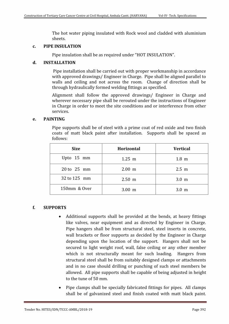
Construction of Tertiary Care Cancer Centre at Civil Hospital, Ambala Cantt. (HARYANA) Vol-IV- Tech. Specifications
Tender No. HITES/IDN/TCCC-AMBL/2018-19 Page 392
The hot water piping insulated with Rock wool and cladded with aluminium sheets.
c. PIPE INSULATION
Pipe insulation shall be as required under “HOT INSULATION”.
d. INSTALLATION
Pipe installation shall be carried out with proper workmanship in accordance with approved drawings/ Engineer in Charge. Pipe shall be aligned parallel to walls and ceiling and not across the room. Change of direction shall be through hydraulically formed welding fittings as specified.
Alignment shall follow the approved drawings/ Engineer in Charge and wherever necessary pipe shall be rerouted under the instructions of Engineer in Charge in order to meet the site conditions and or interference from other services.
e. PAINTING
Pipe supports shall be of steel with a prime coat of red oxide and two finish coats of matt black paint after installation. Supports shall be spaced as follows:
Size Horizontal Vertical
Upto 15 mm 1.25 m 1.8 m
20 to 25 mm 2.00 m 2.5 m
32 to 125 mm 2.50 m 3.0 m
150mm & Over 3.00 m 3.0 m
f. SUPPORTS
Additional supports shall be provided at the bends, at heavy fittings
like valves, near equipment and as directed by Engineer in Charge.
Pipe hangers shall be from structural steel, steel inserts in concrete,
wall brackets or floor supports as decided by the Engineer in Charge
depending upon the location of the support. Hangers shall not be
secured to light weight roof, wall, false ceiling or any other member
which is not structurally meant for such loading. Hangers from
structural steel shall be from suitably designed clamps or attachments
and in no case should drilling or punching of such steel members be
allowed. All pipe supports shall be capable of being adjusted in height
to the tune of 50 mm.
Pipe clamps shall be specially fabricated fittings for pipes. All clamps
shall be of galvanized steel and finish coated with matt black paint.
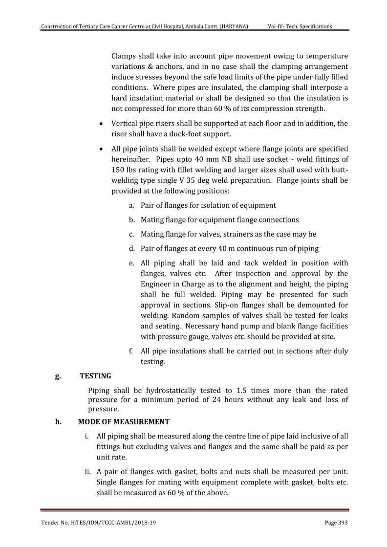
Construction of Tertiary Care Cancer Centre at Civil Hospital, Ambala Cantt. (HARYANA) Vol-IV- Tech. Specifications
Tender No. HITES/IDN/TCCC-AMBL/2018-19 Page 393
Clamps shall take into account pipe movement owing to temperature
variations & anchors, and in no case shall the clamping arrangement
induce stresses beyond the safe load limits of the pipe under fully filled
conditions. Where pipes are insulated, the clamping shall interpose a
hard insulation material or shall be designed so that the insulation is
not compressed for more than 60 % of its compression strength.
Vertical pipe risers shall be supported at each floor and in addition, the
riser shall have a duck-foot support.
All pipe joints shall be welded except where flange joints are specified
hereinafter. Pipes upto 40 mm NB shall use socket - weld fittings of
150 lbs rating with fillet welding and larger sizes shall used with butt-
welding type single V 35 deg weld preparation. Flange joints shall be
provided at the following positions:
a. Pair of flanges for isolation of equipment
b. Mating flange for equipment flange connections
c. Mating flange for valves, strainers as the case may be
d. Pair of flanges at every 40 m continuous run of piping
e. All piping shall be laid and tack welded in position with
flanges, valves etc. After inspection and approval by the
Engineer in Charge as to the alignment and height, the piping
shall be full welded. Piping may be presented for such
approval in sections. Slip-on flanges shall be demounted for
welding. Random samples of valves shall be tested for leaks
and seating. Necessary hand pump and blank flange facilities
with pressure gauge, valves etc. should be provided at site.
f. All pipe insulations shall be carried out in sections after duly
testing.
g. TESTING
Piping shall be hydrostatically tested to 1.5 times more than the rated pressure for a minimum period of 24 hours without any leak and loss of pressure.
h. MODE OF MEASUREMENT
i. All piping shall be measured along the centre line of pipe laid inclusive of all
fittings but excluding valves and flanges and the same shall be paid as per
unit rate.
ii. A pair of flanges with gasket, bolts and nuts shall be measured per unit.
Single flanges for mating with equipment complete with gasket, bolts etc.
shall be measured as 60 % of the above.
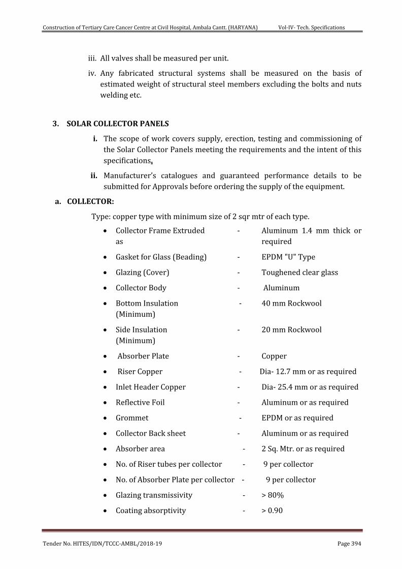
Construction of Tertiary Care Cancer Centre at Civil Hospital, Ambala Cantt. (HARYANA) Vol-IV- Tech. Specifications
Tender No. HITES/IDN/TCCC-AMBL/2018-19 Page 394
iii. All valves shall be measured per unit.
iv. Any fabricated structural systems shall be measured on the basis of
estimated weight of structural steel members excluding the bolts and nuts
welding etc.
3. SOLAR COLLECTOR PANELS
i. The scope of work covers supply, erection, testing and commissioning of
the Solar Collector Panels meeting the requirements and the intent of this
specifications.
ii. Manufacturer’s catalogues and guaranteed performance details to be
submitted for Approvals before ordering the supply of the equipment.
a. COLLECTOR:
Type: copper type with minimum size of 2 sqr mtr of each type.
Collector Frame Extruded - Aluminum 1.4 mm thick or
as required
Gasket for Glass (Beading) - EPDM "U" Type
Glazing (Cover) - Toughened clear glass
Collector Body - Aluminum
Bottom Insulation - 40 mm Rockwool
(Minimum)
Side Insulation - 20 mm Rockwool
(Minimum)
Absorber Plate - Copper
Riser Copper - Dia- 12.7 mm or as required
Inlet Header Copper - Dia- 25.4 mm or as required
Reflective Foil - Aluminum or as required
Grommet - EPDM or as required
Collector Back sheet - Aluminum or as required
Absorber area - 2 Sq. Mtr. or as required
No. of Riser tubes per collector - 9 per collector
No. of Absorber Plate per collector - 9 per collector
Glazing transmissivity - > 80%
Coating absorptivity - > 0.90
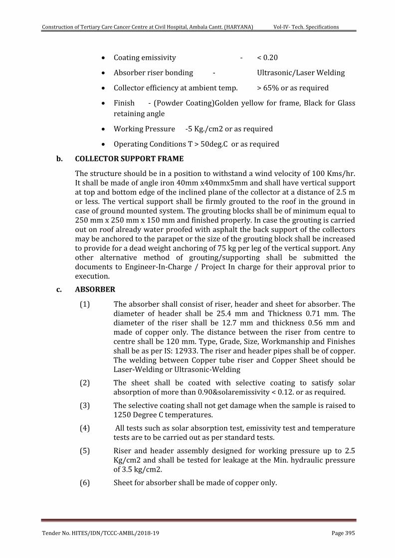
Construction of Tertiary Care Cancer Centre at Civil Hospital, Ambala Cantt. (HARYANA) Vol-IV- Tech. Specifications
Tender No. HITES/IDN/TCCC-AMBL/2018-19 Page 395
Coating emissivity - < 0.20
Absorber riser bonding - Ultrasonic/Laser Welding
Collector efficiency at ambient temp. > 65% or as required
Finish - (Powder Coating)Golden yellow for frame, Black for Glass
retaining angle
Working Pressure -5 Kg./cm2 or as required
Operating Conditions T > 50deg.C or as required
b. COLLECTOR SUPPORT FRAME
The structure should be in a position to withstand a wind velocity of 100 Kms/hr. It shall be made of angle iron 40mm x40mmx5mm and shall have vertical support at top and bottom edge of the inclined plane of the collector at a distance of 2.5 m or less. The vertical support shall be firmly grouted to the roof in the ground in case of ground mounted system. The grouting blocks shall be of minimum equal to 250 mm x 250 mm x 150 mm and finished properly. In case the grouting is carried out on roof already water proofed with asphalt the back support of the collectors may be anchored to the parapet or the size of the grouting block shall be increased to provide for a dead weight anchoring of 75 kg per leg of the vertical support. Any other alternative method of grouting/supporting shall be submitted the documents to Engineer-In-Charge / Project In charge for their approval prior to execution.
c. ABSORBER
(1) The absorber shall consist of riser, header and sheet for absorber. The diameter of header shall be 25.4 mm and Thickness 0.71 mm. The diameter of the riser shall be 12.7 mm and thickness 0.56 mm and made of copper only. The distance between the riser from centre to centre shall be 120 mm. Type, Grade, Size, Workmanship and Finishes shall be as per IS: 12933. The riser and header pipes shall be of copper. The welding between Copper tube riser and Copper Sheet should be Laser-Welding or Ultrasonic-Welding
(2) The sheet shall be coated with selective coating to satisfy solar absorption of more than 0.90&solaremissivity < 0.12. or as required.
(3) The selective coating shall not get damage when the sample is raised to 1250 Degree C temperatures.
(4) All tests such as solar absorption test, emissivity test and temperature tests are to be carried out as per standard tests.
(5) Riser and header assembly designed for working pressure up to 2.5 Kg/cm2 and shall be tested for leakage at the Min. hydraulic pressure of 3.5 kg/cm2.
(6) Sheet for absorber shall be made of copper only.
Construction of Tertiary Care Cancer Centre at Civil Hospital, Ambala Cantt. (HARYANA) Vol-IV- Tech. Specifications
Tender No. HITES/IDN/TCCC-AMBL/2018-19 Page 396
d. STAND
The stand for the collector and hot water storage tank are to be designed taking into consideration the load to be carried by the stand. The collector becomes vulnerable to wind dust. The collector may be up-listed by wind striking the underside. This wind load should be determined according to accepted engineering practices and procedures. The material for collector stand shall be of size 32 x32 x 3 mm M.S. Angle iron with one coat of red oxide primer and two or more coats of enamel paint.
e. SOLAR HEAT BANK TANK
The material of the Solar Heat Bank shall be MS Sheet. & capacity shall be 10,000 Liters. The thickness of the Solar Heat Bank Tank shall be 6 mm shell and 8 mm dish ends. The tank shall have a Manhole of dia. min. 450mm & have a special layer of Resin Bonded Fiberglas Coating inside the tank to prevent corrosion. The tank shall be semi-pressurized type with air vents
f. SOLAR MIXING TANK
The material of the Solar Mixing Tank shall be SS-304 Sheet. & capacity shall be as per requirements. The thickness of the Mixing Tank shall be 3mm shell and 4 mm dish ends. A special layer of QUARTZ coating inside the tank to prevent corrosion shall be provided. The tank shall be non-pressurized type with air vents
g. TANK INSULATION
Both the Hot Water Tanks shall be insulated with 100 mm thick rock/glass wool of 48 Kg/m3 of density & clad with 24 SWG Aluminium cladding.
h. PLATE HEAT EXCHANGER
The Plate Heat Exchanger for Heat Transfer & Control (HTC) application shall be made of SS-316 plates. The capacity for heat transfer should be as per requirements.
i. SYSTEM INTERCONNECTING PIPING
G.I. Pipe of Medium class as per IS: 1239 duly insulated with 13mm Nitrile Tube & clad with polyshield outer mechanical protection on nitrile rubber insulation, comprising of wrapping with poly-glass tape helically wound and subsequently applying 2 coats of polyshield material(resin & hardener)as per manufacturer specification and approved by Engineer-in-charge.
j. MAKEUP TANK
The capacity of Makeup tank for solar circuit shall be 200 Ltr. or as required complete with float valve and interconnection piping as required. Soft water is to be provided for the makeup tank by client
k. ELECTRICAL HEATER
Electrical Heater shall be ISI Marked. Electrical heater shall be of 12 nos. each of rating 5 KW for the 5000 Liter Mixing Tank or as required.
Construction of Tertiary Care Cancer Centre at Civil Hospital, Ambala Cantt. (HARYANA) Vol-IV- Tech. Specifications
Tender No. HITES/IDN/TCCC-AMBL/2018-19 Page 397
l. ELECTRICAL HEATER CONTROL PANEL
The Electrical Heater System shall be split in 2 zones of 30KW each or as required & shall be having Thermo-Sensor based operation. Electric Heater Control Panel of total 60kW rating shall be part of the main Control Panel as the Heater Control Zone.
m. PUMPS FOR FORCED CIRCULATION, HTC & RE_CIRCULATION OPERATIONS
All Pumps used in the solar system for Forced Circulation, HTC & Re-Circulation Systems shall be Horizontal type with Centrifugal operation & having SS Impeller & Shaft and with CI Body. All Pumps shall be suitable for 3-Phase Operation & shall be for 1Working &1Standby mode.
n. CONTROL PANEL FOR PUMP OPERATION
The Operation of the Pumps in the above operations shall be DOL Starter based with adequate rating. The Main Control Panel Shall be sub-divided into sub-Zones :
Forced Circulation Zone
Heat Transfer & Control Zone (for Primary & Secondary Pump sets)
Hot Water Re-Circulation in Building Zone
Note: Contractor shall provide Control Panel with makes as specified in the list of approved makes with digital differential temperature controller / PLC including necessary electronic parts like Contractors, Relays, Indicators, MCBs, Control fuses etc. for satisfactory working of pumps.
o. TEMPERATURE GAUGE
DIAL Type temperature gauge duly calibrated and suitable for temperature range 0-120 deg. Celsius shall be provided.
Contractor shall provide all valves, strainer, float valves and NRV etc. as per requirement.
Contractor shall provide 1:2:4 cement concrete foundation of size 300x300x250 mm (1 cement: 2 coarse sand: 4 stone aggregate of size 20 mm nominal size) for each and every footing of system. This will be scope of Civil Contractor with complete guidance from Solar Contractor.
p. PAINTING OF STANDS
Proper cleaning and degreasing of the surface should be done before painting. Two coats of zinc chromate red oxide primer shall be applied followed by one coat of epoxy paint and approved colour recommended by the CLIENT/ HITES.
q. PIPING
a) Material : Medium class (B class) GI as per IS 1239 shall be used for piping.
b) Back insulation : Insulation of R value = 1.67 m2 °C/W to withstand a temperature of 100°C shall be used.
Construction of Tertiary Care Cancer Centre at Civil Hospital, Ambala Cantt. (HARYANA) Vol-IV- Tech. Specifications
Tender No. HITES/IDN/TCCC-AMBL/2018-19 Page 398
Typical insulation detail shown below and also conforming to ECBC standards.
Thin plastic sheet shall be used as covering between glass wool and aluminum cladding besides other retaining material like chicken mesh etc.
24 SWG aluminium sheet shall be used for cladding the insulated pipe.
r. VALVES / NIPPLE / TEES / BENDS
Gun metal valve as per IS 780 specifications shall be used.
Nipple / Tees and bends shall be of GI as per IS 1239 Part II.
Gun metal ball valve shall be provided in each row outlet with Air vent.
s. VALVES
Gate valves or butterfly valves for shut-off or sectionalizing service, globe or ball valves for flow modulation. For on-site control, use gate valves. Specialty valve shall be employed where appropriate, such as check valves on a pump discharge, pressure regulating valves for equipment requiring lower-than-available system pressure, solenoid valves, etc. Flanged or threaded end valves are preferred. Locate valves in accessible locations, not more than six feet above the floor, if frequently used, and with a union on the downstream side of threaded end valves.
Provide each valve with brass, aluminum or plastic disc not les than 32mm diameter engraved with numbers, piping service and normal operating position (i.e. NO, NC) corresponding to valves shown on the diagram. Fasten disc to valve with 14gauge brass wire or 16gauge jack chain.
t. GATE VALVE
The primary function of a gate valve is for starting and stopping of flow. It has a disc actuated by a stem screw and hand wheel, moves up and down at right angles to the path of flow of fluid and seats against two faces to shut of flow. As the disc of the gate valve presents a flat surface to the direction of flow, this valve is only for starting and shutting the flow in the pipe.
These valves are of Gun Metal (GM) make. Supplying, fixing and testing correspond to IS 778-1984, Specifications for Copper Alloy Gate, Globe and Check Valves for Water Works.
All globe and check valves shall have working parts suitable for hot and cold water, as required. Valves shall be tagged with permanent label under hand wheel indicating type or duty.
All valves should have manufacturer’s test certificate indicating the date of shop test and other quality control tests with the material used for the same.
u. BALL VALVE
The ball valve shall be of high-pressure type and shall be of sizes as specified and/or shown in the drawings the normal size of a ball valve shall be that, corresponding to the size of the pipe to which it is fixed. Ball valves shall have body of carbon steel. The ball and the shaft shall be of stainless steel. The seat shall be of PTFE.
Construction of Tertiary Care Cancer Centre at Civil Hospital, Ambala Cantt. (HARYANA) Vol-IV- Tech. Specifications
Tender No. HITES/IDN/TCCC-AMBL/2018-19 Page 399
The valve shall be complete with socket weld ends and the float of copper sheet. The minimum thickness of copper sheet used for making the float shall be 0.45mm for a float exceeding 115mm dia. The body of the high-pressure ball valve when assembled in working condition with the float immersed to not more than half of its diameter shall remain closed against a test pressure of 3.5kg/sqcm.
The ball valve shall generally conform to IS specification No.1703: 1977. The weight of ball cock and the size of the ball cock shall be as per IS specification.
v. SYSTEM LAYOUT AND DESIGN
Maximum number of collector in series shall be not more than Ten for Thermosyphon system and not more than 15 for force circulation system.
Maximum number of collector in parallel in one row with header to header connections should not be more than Six.
Air venting at appropriate places without hindrance of a spring loaded valve to prevent air locking in the system should be provided. For this purpose system shall have at a suitable point atmospheric pressure conditions preferably in the high temperature zone.Flow rates commensurate with optimum heat removal from collector plates.
System shall have a suitable expansion / make up tank at a high point in the system to ensure that collectors run full all the times. Capacity of this expansion make up tank should be 1% of the system capacity.
For all systems above the capacity of 5000 LPD and 1.5% of the system capacity for the systems of capacity ranging from 1000 LPD to 5000 LPD.
Expansion cum make-up tank is for closed loop system and make up tank is for open loop system.
4. HEAT PUMPS
The Packaged type Air to Water Heat Pump. shall be completely factory assembled including required Nos. of Scroll Hermetically Sealed Scroll / Reciprocating Compressor(s), evaporator, Condenser and Microprocessor Control Panel etc with R134a / 410 a/ 470 c or any other CFC free Refrigerant and COP between 3-4.
The Heat Pump shall have inbuilt hot water heat exchanger, vibration isolators, pumps, valves, expansion valve, Copper / Aluminium fins, and other accessories. The Heat Pump should be capable of producing hot water at minimum 55°C temperature at outlet (condenser circuit) temperatures at approx. 40°C ∆T. The Machine should have an operating ambient temperature range of 0°C to 40°C.
Heat Pump shall have built in electric panel as per safety norms as manufacturer standard. It shall be Suitable for electric supply of 415 + 10% volts & 50 Hz. The Heat pump shall have an in-built facility to start / stop depending on variation in demand at different periods. All interconnecting wiring / cabling between heat pump and electrical panel shall be part of the
Construction of Tertiary Care Cancer Centre at Civil Hospital, Ambala Cantt. (HARYANA) Vol-IV- Tech. Specifications
Tender No. HITES/IDN/TCCC-AMBL/2018-19 Page 400
equipment. The heat pump should be designed at ambient temperature at 7 degree celcius considering de-aeration of Equipment.
SS 304 horizontal hot water storage tank of required capacity suitable for minimum 7 kg/sqcm operating pressure. Tank shall be provided with hot water flow meter at inlet & outlet, inlet/outlet, overflow/drain connections with MH cover, pressure relieve valve, pressure gauge at inlet/outlet with isolation cock & thermometer. Tank shall be provided with 24 G aluminium cladding. It shall eb provided with 15 mm dia. testing spout with valve. The Heat Pumps shall be installed in N+1 condition at terrace level of hospital building.
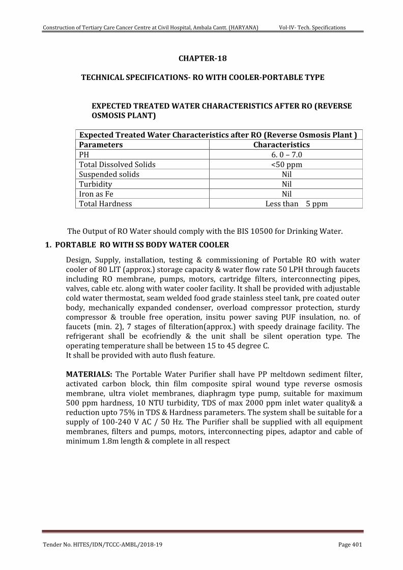
Construction of Tertiary Care Cancer Centre at Civil Hospital, Ambala Cantt. (HARYANA) Vol-IV- Tech. Specifications
Tender No. HITES/IDN/TCCC-AMBL/2018-19 Page 401
CHAPTER-18
TECHNICAL SPECIFICATIONS- RO WITH COOLER-PORTABLE TYPE
EXPECTED TREATED WATER CHARACTERISTICS AFTER RO (REVERSE OSMOSIS PLANT)
Expected Treated Water Characteristics after RO (Reverse Osmosis Plant ) Parameters Characteristics PH 6. 0 – 7.0 Total Dissolved Solids <50 ppm Suspended solids Nil Turbidity Nil Iron as Fe Nil Total Hardness Less than 5 ppm
The Output of RO Water should comply with the BIS 10500 for Drinking Water.
1. PORTABLE RO WITH SS BODY WATER COOLER
Design, Supply, installation, testing & commissioning of Portable RO with water cooler of 80 LIT (approx.) storage capacity & water flow rate 50 LPH through faucets including RO membrane, pumps, motors, cartridge filters, interconnecting pipes, valves, cable etc. along with water cooler facility. It shall be provided with adjustable cold water thermostat, seam welded food grade stainless steel tank, pre coated outer body, mechanically expanded condenser, overload compressor protection, sturdy compressor & trouble free operation, insitu power saving PUF insulation, no. of faucets (min. 2), 7 stages of filteration(approx.) with speedy drainage facility. The refrigerant shall be ecofriendly & the unit shall be silent operation type. The operating temperature shall be between 15 to 45 degree C. It shall be provided with auto flush feature. MATERIALS: The Portable Water Purifier shall have PP meltdown sediment filter, activated carbon block, thin film composite spiral wound type reverse osmosis membrane, ultra violet membranes, diaphragm type pump, suitable for maximum 500 ppm hardness, 10 NTU turbidity, TDS of max 2000 ppm inlet water quality& a reduction upto 75% in TDS & Hardness parameters. The system shall be suitable for a supply of 100-240 V AC / 50 Hz. The Purifier shall be supplied with all equipment membranes, filters and pumps, motors, interconnecting pipes, adaptor and cable of minimum 1.8m length & complete in all respect
Construction of Tertiary Care Cancer Centre at Civil Hospital, Ambala Cantt. (HARYANA) Vol-IV- Tech. Specifications
Tender No. HITES/IDN/TCCC-AMBL/2018-19 Page 402
CHAPTER -19
TECHNICAL SPECIFICATION - LIFTS
The scope of work shall cover design, supply delivery, installation, testing and
commissioning of passenger lifts/ passenger cum bed lifts/Service lifts. All lifts shall
be VVVF operated, gearless, Central opening and with Machine room. The Lifts shall
be with facility for duplex/triplex seclective/collective operation. Car enclosure fininsh
shall be SS (as per OEM) scratch proof moonrock/honeycomb. SS handrail not less
than 600mm long at 900mm above floor level , to be provided inside the lift car as per
requirement. Suitable lights and fans as per requirement shall be provided. Lift car
size, Lift well size, Lift pit overhead, entrance width, car height etc. shall be as per NBC
2016 or OEM standards. The dimensions of Lift well shown in tender drawings are
only indicative and EPC contractor shall provide the same as required by OEM.
The scope of work shall also include the following item of civil works.
a) Necessary scaffolding temporary barricade in the hoist way required during
the erection of the elevators.
b) Minor building work comprising of cutting holes and making good the car
and counterweight rail brackets, hall buttons and indicators including laying
of sills in position.
c) Steel items such as machine beams, bearing plates buffer support channels,
sill angles and fascia plates etc.
d) Suitable trap doors with steel chequered plate covers.
e) Providing and install a suitable vertical iron ladder for access to the pit.
f) Any other item required for successful completion and commissioning of
lifts. (including the hoisting beam in the machine room)
The work shall be done in accordance with regulations of any local code and
following ISI codes which govern the requirements of installations.
IS: 1860-1980 code of practice for installation, operation and
maintenance of Electric Passenger and Goods Lifts.
IS: 3534-1976 Outline dimensions of Electric Lifts.
IS: 4666-1980 Specifications for Electric passenger and Goods Elevators.
Indian Electricity Act 1910.
Indian Electricity Rules, 1956.
The lift motor shall be controlled by a variable voltage variable frequency (V.V.V.F.)
micro- processor control system which shall control and monitor every aspect of lift
operation at all stages of the car motion cycle on real time basis. Variable voltage
variable frequency drive system (with close loop) shall be used.
Construction of Tertiary Care Cancer Centre at Civil Hospital, Ambala Cantt. (HARYANA) Vol-IV- Tech. Specifications
Tender No. HITES/IDN/TCCC-AMBL/2018-19 Page 403
SHOP DRAWINGS AND APPROVAL OF ELECTRICAL INSTALLATIONS :
The selected tenderer shall prepare a furnish shop drawings for approval by The
Client, such shop drawings shall be based on the Architectural drawings and
requirements laid down in specifications, local laws and regulations etc.
The detailed drawings shall be submitted within one month of placement of order.
The successful tenderer shall obtain the approval of electrical Inspector and other
local authorities as per requirements before submitting the drawings to Client/
Engineer. The contractor shall not proceed with in installation work till the drawings
are approved by the Engineer-in-Charge.
Approval of contractor's drawings shall not absolve the contractor of any of his
obligations to meet the requirements of specification under this contract
Five sets of completion drawings operation manual, maintenance manual, spare
parts details shall be submitted to the Client/ Engineer after completion of work.
GUARANTEE
The contractor shall guarantee the equipment against all defects of materials and
workmanship for a period of one year from the date of Handing over of the
equipment as certified by the owner. Any defects arising during the guarantee period
shall be rectified and replaced by the tenderer, at his own expense, to the satisfaction of
the owner.
PERMITS, INSPECTION & LICENSE FEE
The contractor shall arrange all necessary local, provincial or national government
permit/License and shall make arrangements for inspection and tests required
thereby. Expenses to be borne by EPC contractor.
POWER SUPPLY
The apparatus shall be designed to operate on 415 + 10% - 20% Volts, 3 Phase, 4
wires, 50 Hz A.C. Supply for illumination signal equipment shall be 240 Volts single
phase 50Hz A.C.
ELECTRICAL WIRING
The necessary A.C. supply of 3 Phase, 415 Volts 50 HZ shall be made available in the
main control switch unit to be provided by the contractor in the machine room. All the
electrical works beyond the main supply switch shall be carried out by the contractor
i.e. supply and installations of panels for drive motors, switches and control complete
with wiring as per system requirement and approval of the Engineer.
The wiring shall be carried out strictly in accordance with Indian Electricity Rules
and Indian code of Practice for Electrical Wiring Installation IS-732-1963 System
Voltage not exceeding 650 V).
The cable and conduits to be used shall be of suitable size and grade conforming to
Construction of Tertiary Care Cancer Centre at Civil Hospital, Ambala Cantt. (HARYANA) Vol-IV- Tech. Specifications
Tender No. HITES/IDN/TCCC-AMBL/2018-19 Page 404
relevant IS specification. Wiring for LT switchboard to the motor terminal shall be
with heavy duty 1.1 KV grade XLPE insulated PVC sheathed, FRLS aluminium cable.
All the trailing cables used for control and safety device shall conform to IS: 4289-
1967, Specifications for lifts cables. The trailing cable circuits for controls, safety devices,
lighting and signaling shall be separate and distinct.
Power wiring between controller and main board to various landings shall be
drawn in suitable size heavy gauge conduit stove enameled/painted conforming to I.S
specifications.
The Voltage and frequency of the supply shall be subjected to variations permissible
under Indian Electricity Acts and Rules.
CAR FRAME:
The car frame, which supports the car platform and enclosures, shall be made of
structural steel and equipped with suitable guides and a car safety device mounted
underneath the car platform. The hoist ropes shall include adjustable self/ aligning
hinges. The car shall be so mounted on the frame that vibration and noise
transmitted to the passenger is minimized.
CAR SAFETY AND GOVERNER :
Suitable car safety to stop the car whenever excessive descending speed is attained shall
be operated by a centrifugal speed governor connected to the governor through a
continuous steel rope.
The governor shall be provided with self tensioning device to keep governor rope
in proper tension even after rope stretch. Suitable means shall be supplied to cut off
power from the motor and apply the brake on application of the safety.
COUNTER BALANCE :
A Suitable guided structural steel frame with appropriate filler weights of cast iron shall
be furnished to promote smooth and economic operation.
TERMINAL AND FINAL LIMITS :
Terminal limit switches shall be provided to slow down and stop the car
automatically at the terminal landings within permissible over travel and final limit
switches shall be provided to automatically cut off the power and apply the brake,
should the car travel beyond the permissible over travel. They shall act
independently of the operating devices and buffers.
TERMINAL BUFFERS :
Heavy duty spring buffers shall be installed as a means of stopping the car and
counterweight at the extreme limits of travel. Buffers in the pit shall be mounted on
steel channels which shall extend between both the car and counterweight rails.
Construction of Tertiary Care Cancer Centre at Civil Hospital, Ambala Cantt. (HARYANA) Vol-IV- Tech. Specifications
Tender No. HITES/IDN/TCCC-AMBL/2018-19 Page 405
CONTROLLER :
A Controller shall be provided to control starting stopping and speed of the elevator
motor and also be automatically able to apply the brake if any of the safety devices
operate or if power fails from any cause. In case of power failure and again restore of
power the lift shall land to next floor and shall not go to basement/lowest level.
Suitable software/hardware or rescue device shall be provided.
REVERSE PHASE RELAY :
A reverse phase relay shall be provided on the controller which is designed to protect
the lift equipment against phase reversal and phase failure.
GUIDES :
Machined steel tee guides shall be furnished for the car and counterweight. The guide
rails should be of steel solid and shall have tongued and grooved joints. Sliding clips
shall be used for fastening the guides to allow building settlement without
distorting the guide rails. To keep down the noise level and to reduce wear and tear of
the sections, only Nylon Ribs shall be used in the guide shoes, after smoothening of the
rails. The flanges shall be machined for the fish plate mounting such that rail
alignment at joints almost remain constant.
FOUNDATIONS :
The machine shall be placed directly above the hoist way upon the machine room
slab provided by the Owner.
ROPES :
The elevator shall be provided with traction steel ropes. Steel wire rope having a
tensile strength of not less that 12.5 Ton/cm2 of good flexibility shall be used for lift.
The lift rope shall conform to IS: 14665 – (Part-4- Sec-8):2001.
MACHINE :
The machine shall be gearless type.
BRAKE :
The direct current brake shall be spring applied and electrically released and
designed to provide smooth stop under variable loads. The brake should be
capable of operation automatically by various safety devices, current failure, and by
normal stopping of car. It should be possible to release the brake manually, such
releases brake manually, such releases requiring the permanent application of
manual force so as to move the lift car in short sties. For this purpose one set of brake
release equipment shall be supplied.
MOTOR :
The motor shall be suited to the service proposed and arranged for adequate
lubrication. The motor shall be class F insulation and one (1) hour rated squirrel
Construction of Tertiary Care Cancer Centre at Civil Hospital, Ambala Cantt. (HARYANA) Vol-IV- Tech. Specifications
Tender No. HITES/IDN/TCCC-AMBL/2018-19 Page 406
cage induction type having high starting torque. It shall also be provided with
Thermisters embedded in the stator windings for the highest degree of thermal
motor protection.
CONTROL
The control shall be variable voltage variable frequency A.C. variable voltage, closed
loop control system using solid state devices and electronic speed pattern
generator to command the motor from a velocity transducer and load
compensation circuits for a comfortable ride.
In Normal operation, the electromagnetic brake shall only be applied when the lift
has come to a complete standstill. The brake shall only be meant for holding the lift in
position at every landing, providing stopping without any jerking effect.
Each controller cabinet containing memory equipment shall be properly shielded from
the pollution.
MICROPROCESSOR
The control shall employ a microprocessor working on a program such that
precision leveling and highly efficient handling of passengers for least possible
waiting and reduced travel time is ensured. The microprocessor system should be
designed to accept programming with minimum downtime. It should be able to
monitor the state of input calls (such as car calls from COP and hall calls from hall
fixtures) and output commands such as starting, decelerating and stopping the
elevator. It should be able to generate floor location data, thereby, providing a reference
position to establish the safety zones for door opening and closing, and also to initiate
leveling slowdown.
DUPLEX COLLECTIVE OPERATION
The operation shall be duplex collective with/without attendant for each elevator and
shall consist of the following:-
IN THE CAR
There shall be furnished a flush type attractively finished stainless steel panel
which contains a series of luminous buttons numbered to correspond to the landings
served, an emergency stop switch and an emergency call button connected to a bell
which serves as an emergency signal.
AT HOISTWAY LANDINGS
There shall be provided an UP luminous push button and a DOWN luminous push
button at each intermediate landing and a single button at the terminal landings.
The car shall not start unless the door is in the closed position and all hoistway doors
are closed in the locked position.
If the car is idle and one or more car or landing buttons above the landing at which the
car is standing are pressed, the car shall start in the UP direction and proceed to the
Construction of Tertiary Care Cancer Centre at Civil Hospital, Ambala Cantt. (HARYANA) Vol-IV- Tech. Specifications
Tender No. HITES/IDN/TCCC-AMBL/2018-19 Page 407
highest landing for which any button is pressed and stops at intermediate landing for
which a car button or up landing button is pressed sufficiently in advance of the car's
arrival at such landings to permit these stops to be made. After each stop, the car shall
proceed in the UP direction until it reaches the highest landing for which a call is
registered. The car shall not stop on the UP trip at any landing in response to a DOWN
call.
Similarly, if the car is idle and one or more car or landing buttons below the landing
at which the car is standing are pressed, the car shall start in the DOWN direction,
proceed to the lowest landing for which any button is pressed and stop at each
intermediate landing for which a car button is pressed.
When the car is idle and a button for a landing above the car and a landing below the
car are pressed, the car shall start towards the landing corresponding to the button
pressed first. The call registered for the landing in the opposite direction from the
car shall be answered after the car has responded to the farthest call in the direction
established by the button pressed first.
A time relay shall hold the car for an adjustable interval of few seconds at the landings
at which stops are made to enable passengers to enter or leave the car.
Lift Voice Announcement:
The lift shall be provided with floor announcement system with volume control.
Lift instructions:
Steel plate containing following instructions shall be provided inside
each lift car:
i. Lift number
ii. Capacity Kg, persons.
iii. Any other instruction as per manufacturer’s standard or other relevant
codes.
Steel plate containing following instructions shall be provided outside
each lift car, on all floors:
i. Lift number
ii. Capacity Kg, persons.
iii. Any other instruction as per manufacturer’s standard or other relevant
codes.
Other Details
a. Work shall be carried out as per CPWD specifications unless
Construction of Tertiary Care Cancer Centre at Civil Hospital, Ambala Cantt. (HARYANA) Vol-IV- Tech. Specifications
Tender No. HITES/IDN/TCCC-AMBL/2018-19 Page 408
otherwise specified.
b. Suitable scaffolding in the hoist way, cutting work and all minor civil
works, if any, required shall be done by contractor without any extra
cost.
d. All steel items in machine room, hoist way and lifting arrangement in the
lift machine room shall be provided by the contractor without any extra
cost.
e. At the time of erection, testing & commissioning of lift works all the
landing door openings shall be suitably protected by the contractor to
avoid any miss happening.
f. All exposed metal parts will be painted with good quality anticorrosive
low VOC paint after erection and before commissioning of the lift.
It should be possible for an attendant to operate any car.
CAR DOOR/LANDING DOOR
The car entrance shall be provided with stainless steel centre opening
doors in moon rock finish or as per direction of Engineer In Charge. The lift
car door shall have a fire resistance rating of two hours.
HOISTWAY DOORS :
At each landing, a center/ telescopic opening , stainless steel sliding door in
plain finish giving a clear opening as per CPWD general specifications for
electrical works
–Part-III – Lifts & Escalators, shall be provided.
SIGNAL AND OPERATIVE FIXTURES :
The following signal and operative fixtures shall be provided for each lift in
stainless steel face plates except in fireman's switch which shall have a glass
face plate.
a) CAR OPERATING PANEL
There shall be one (1) No. panel in car, with hinged stainless steel face plate
and shall comprise Braille illuminated floor buttons, door open and
emergency stop controls emergency call buttons, door open and emergency
stop controls emergency call button, two position key operated switch, a
Buzzer, UP and DOWN direction light panels, a non stop button, and an integral
interphone. The jewels and accentuator shall be of modular construction, face
plate mounted, rewired using snap on lugs.
b) HALL BUTTONS AND HALL POSITION INDICATOR
There shall be provided combined signal fixture (one riser) of compact design
and of attractive hairline stainless steel face plate at the elevator entrance on
Construction of Tertiary Care Cancer Centre at Civil Hospital, Ambala Cantt. (HARYANA) Vol-IV- Tech. Specifications
Tender No. HITES/IDN/TCCC-AMBL/2018-19 Page 409
each floor which for terminal landings shall have a single luminous push
button and for intermediate landings shall have an UP Braille illuminated push
button and a DOWN Braille illuminated push button. The jewels shall be of
modular construction mounted on a stainless steel face plate. Whenever a
button is pressed, the jewel shall light up to indicate registration of the call
and shall remain enlighted till the car arrives.
c) CAR POSITION INDICATOR IN CAR
This shall be of compact design and of attractive hairline finish stainless steel
face plate with easy to read digital display of the floors, indicating through
which floor the elevator is passing or on which floor the elevator is stopped.
This shall also incorporate illuminated arrows showing the direction of
travel.
d) BATTERY OPERATED ALARM BELL AND EMERGENCY LIGHT
A solid state siren type alarm unit operated by 2 Nos. 9 volt rechargeable
Nickel Cadmium batteries shall be provided which shall give a waxing and
waning siren when alarm bell in the car is pressed momentarily.
An emergency light unit using a 9 volt dry battery power pack and
incandescent lamp with stainless steel face plate shall be provided inside
the car which shall operate automatically in the case of power failure.
e) OVERLOAD WARNING
Overload warning radars with audio-visual indication (visual indication shall
show OVERLOADED) with stainless steel face plate shall be installed in the
elevator car, so that when there is overload in the car the sign shall light up a
flash indicating OVERLOADED and a buzzer shall operate during this period
and the doors shall remain open unit the overload is removed.
f) FIREMAN'S SWITCH
A toggle switch covered by a glass cover shall be provided on the ground floor
for each elevator which shall permit a fireman to call the elevator to the ground
floor by canceling all car and landing calls. The elevator shall then stop at the
ground floor with the door open to permit the fireman to have exclusive use
of the elevator without any interference from the landing calls.
g) INTERPHONE
Interphone shall have one master unit in each machine room, one master
unit on the ground floor for each 1 (outside hoist way) and one slave unit in
each elevator car.
ELECTRIC DOOR OPERATOR FOR CAR DOOR AND HOISTWAY DOOR :
An electric door operator for opening and closing the car door shall b e
Construction of Tertiary Care Cancer Centre at Civil Hospital, Ambala Cantt. (HARYANA) Vol-IV- Tech. Specifications
Tender No. HITES/IDN/TCCC-AMBL/2018-19 Page 410
provided. The opening of a car and hoist way doors shall be such that the
doors shall start opening meant for so that by the time the elevator stops
completely, the elevator and hoist way doors shall be fully open.
The equipment shall consist of a machine on the elevator car operating the car
door when the car is stopping at a landing.
The car door and hoist way door shall be mechanically connected and shall
move simultaneously in opening and closing.
The car and hoist way doors shall be power opened and closed and shall be
checked in opening and closing with an oil cushioning mechanism built into the
gear unit.
Each hoist way door shall be provided with an interlock which will prevent
movement of the car away from the landing unit.
The doors are closed in the closed position as defined in the ISI codes.
An electric contact for the car door shall be provided which shall prevent
car movement from the landing unless the door is in the closed position as
defined in the ISI codes. The locking arrangement shall be so designed that
the electrical circuit cannot be completed unless the doors are in the closed
position and mechanical latching is effected.
Necessary switches shall be provided in the elevator machine room to control
the operation of the doors.
The car and hoist way, doors shall open automatically as the car is stopping
at a landing. The closing of the car and hoist way door must occur before the car
can be started. Doors can be stopped and reversed during their closing motion.
DOOR HANGER AND TRACKS :
For the car and each landing door, sheave type two point suspension
hangers complete with tracks shall be provided. Means shall be provided to
prevent the door from jumping off the track and for vertical and literal
adjustment of doors.
Sheaves and rollers shall be of steel and shall include shielded ball bearing to
retain grease lubrication. Adjustable ball bearings rollers shall be provided
to take the upward thrust of the doors. Tracks shall be of suitable steel
section with smooth surface. The locking of the two leaf parting type doors
should be positive.
SAFETY SENSOR:
A safety sensor(one on each door panel) shall extend to the full height of the car door.
LANDING ENTRANCE MATERIAL'S :
These shall consist of headers, extruded aluminium sills and strut angles.
Construction of Tertiary Care Cancer Centre at Civil Hospital, Ambala Cantt. (HARYANA) Vol-IV- Tech. Specifications
Tender No. HITES/IDN/TCCC-AMBL/2018-19 Page 411
WIRING :
Complete wiring in the equipment room from controller to various landings shall be
done in heavy gauge conduit / metal duct & shall confirm to IE rules 1956 . DC
power & AC power shall not run in same conduit / duct and they shall be laid as per IE
rules.
AUTOMATIC RESCUE DEVICE:
Automatic Rescue Device to be provided for all the lifts with battery backup so that it
can land to the nearest level in case of power failure. Automatic Rescue Device
shall have suitable battery backup so that it can operate minimum seven times in a day
provided the duration between usage is at least 30 minutes.
TESTING OF LIFTS
The contractor after the installation of the lifts has to conduct the following test and furnish the
readings to ascertain the performance of the lifts.
1. Levelling Test :
2. Safety Gear Test :
3. Contract Speed Test :
4. Lift Balance :
5. Car and Landing Interlock Test :
6. Controllers Test :
7. Normal Terminal Stopping Switches :
8. Final Terminal Stopping Switches :
9. Insulation Resistance Test :
10. Ropes :
11. Buffer Test :
12. Earthing :
13. Performance Test :
List of IS codes for Lift installations applicable is given below:
1. Code of Practice for installation, operation and IS-1860
Maintenance of electric passenger & goods lifts.
2. Code of Practice for installation, operation and IS-6620
Maintenance of electric service lift.
3. Specification for electric passenger & goods lifts IS-4666
4. Electric service lift. IS-6383
5. Online dimension for electric lifts IS-3534
6. Code of practice for installation and maintenance IS-4591
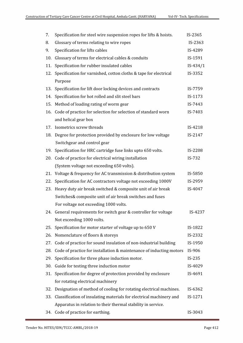
Construction of Tertiary Care Cancer Centre at Civil Hospital, Ambala Cantt. (HARYANA) Vol-IV- Tech. Specifications
Tender No. HITES/IDN/TCCC-AMBL/2018-19 Page 412
7. Specification for steel wire suspension ropes for lifts & hoists. IS-2365
8. Glossary of terms relating to wire ropes IS-2363
9. Specification for lifts cables IS-4289
10. Glossary of terms for electrical cables & conduits IS-1591
11. Specification for rubber insulated cables IS-434/1
12. Specification for varnished, cotton cloths & tape for electrical IS-3352
Purpose
13. Specification for lift door locking devices and contracts IS-7759
14. Specification for hot rolled and slit steel bars IS-1173
15. Method of loading rating of worm gear IS-7443
16. Code of practice for selection for selection of standard worn IS-7403
and helical gear box
17. Isometrics screw threads IS-4218
18. Degree for protection provided by enclosure for low voltage IS-2147
Switchgear and control gear
19. Specification for HRC cartridge fuse links upto 650 volts. IS-2208
20. Code of practice for electrical wiring installation IS-732
(System voltage not exceeding 650 volts).
21. Voltage & frequency for AC transmission & distribution system IS-5850
22. Specification for AC contractors voltage not exceeding 1000V IS-2959
23. Heavy duty air break switched & composite unit of air break IS-4047
Switches& composite unit of air break switches and fuses
For voltage not exceeding 1000 volts.
24. General requirements for switch gear & controller for voltage IS-4237
Not exceeding 1000 volts.
25. Specification for motor starter of voltage up to 650 V IS-1822
26. Nomenclature of floors & storeys IS-2332
27. Code of practice for sound insulation of non-industrial building IS-1950
28. Code of practice for installation & maintenance of inducting motors IS-906
29. Specification for three phase induction motor. IS-235
30. Guide for testing three induction motor IS-4029
31. Specification for degree of protection provided by enclosure IS-4691
for rotating electrical machinery
32. Designation of method of cooling for rotating electrical machines. IS-6362
33. Classification of insulating materials for electrical machinery and IS-1271
Apparatus in relation to their thermal stability in service.
34. Code of practice for earthing. IS-3043
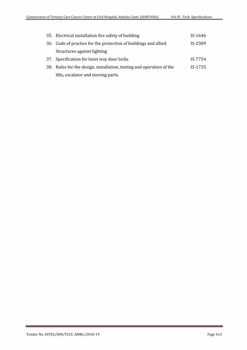
Construction of Tertiary Care Cancer Centre at Civil Hospital, Ambala Cantt. (HARYANA) Vol-IV- Tech. Specifications
Tender No. HITES/IDN/TCCC-AMBL/2018-19 Page 413
35. Electrical installation fire safety of building IS-1646
36. Code of practice for the protection of buildings and allied IS-2309
Structures against lighting
37. Specification for hoist way door locks IS-7754
38. Rules for the design, installation, testing and operation of the IS-1735
lifts, escalator and moving parts.
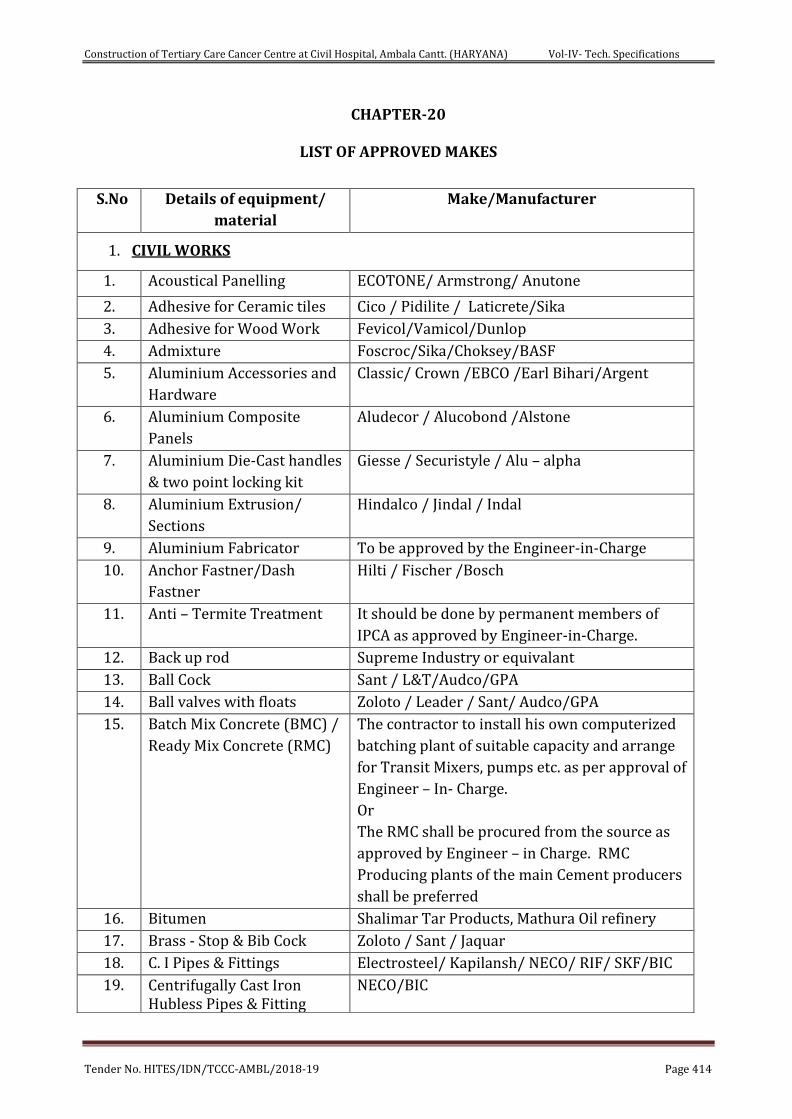
Construction of Tertiary Care Cancer Centre at Civil Hospital, Ambala Cantt. (HARYANA) Vol-IV- Tech. Specifications
Tender No. HITES/IDN/TCCC-AMBL/2018-19 Page 414
CHAPTER-20
LIST OF APPROVED MAKES
S.No Details of equipment/
material
Make/Manufacturer
1. CIVIL WORKS
1. Acoustical Panelling ECOTONE/ Armstrong/ Anutone
2. Adhesive for Ceramic tiles Cico / Pidilite / Laticrete/Sika
3. Adhesive for Wood Work Fevicol/Vamicol/Dunlop
4. Admixture Foscroc/Sika/Choksey/BASF
5. Aluminium Accessories and
Hardware
Classic/ Crown /EBCO /Earl Bihari/Argent
6. Aluminium Composite
Panels
Aludecor / Alucobond /Alstone
7. Aluminium Die-Cast handles
& two point locking kit
Giesse / Securistyle / Alu – alpha
8. Aluminium Extrusion/
Sections
Hindalco / Jindal / Indal
9. Aluminium Fabricator To be approved by the Engineer-in-Charge
10. Anchor Fastner/Dash
Fastner
Hilti / Fischer /Bosch
11. Anti – Termite Treatment It should be done by permanent members of
IPCA as approved by Engineer-in-Charge.
12. Back up rod Supreme Industry or equivalant
13. Ball Cock Sant / L&T/Audco/GPA
14. Ball valves with floats Zoloto / Leader / Sant/ Audco/GPA
15. Batch Mix Concrete (BMC) /
Ready Mix Concrete (RMC)
The contractor to install his own computerized
batching plant of suitable capacity and arrange
for Transit Mixers, pumps etc. as per approval of
Engineer – In- Charge.
Or
The RMC shall be procured from the source as
approved by Engineer – in Charge. RMC
Producing plants of the main Cement producers
shall be preferred
16. Bitumen Shalimar Tar Products, Mathura Oil refinery
17. Brass - Stop & Bib Cock Zoloto / Sant / Jaquar
18. C. I Pipes & Fittings Electrosteel/ Kapilansh/ NECO/ RIF/ SKF/BIC
19. Centrifugally Cast Iron Hubless Pipes & Fitting
NECO/BIC
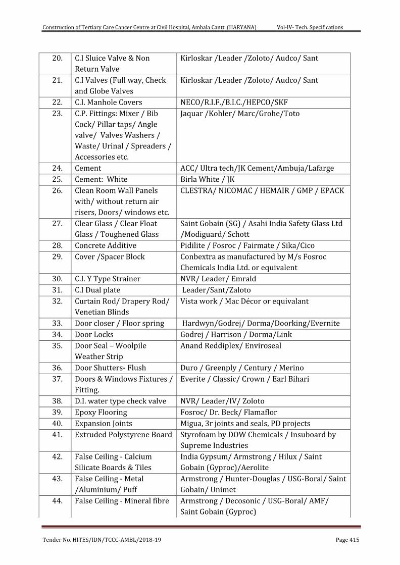
Construction of Tertiary Care Cancer Centre at Civil Hospital, Ambala Cantt. (HARYANA) Vol-IV- Tech. Specifications
Tender No. HITES/IDN/TCCC-AMBL/2018-19 Page 415
20. C.I Sluice Valve & Non
Return Valve
Kirloskar /Leader /Zoloto/ Audco/ Sant
21. C.I Valves (Full way, Check
and Globe Valves
Kirloskar /Leader /Zoloto/ Audco/ Sant
22. C.I. Manhole Covers NECO/R.I.F./B.I.C./HEPCO/SKF
23. C.P. Fittings: Mixer / Bib
Cock/ Pillar taps/ Angle
valve/ Valves Washers /
Waste/ Urinal / Spreaders /
Accessories etc.
Jaquar /Kohler/ Marc/Grohe/Toto
24. Cement ACC/ Ultra tech/JK Cement/Ambuja/Lafarge
25. Cement: White Birla White / JK
26. Clean Room Wall Panels
with/ without return air
risers, Doors/ windows etc.
CLESTRA/ NICOMAC / HEMAIR / GMP / EPACK
27. Clear Glass / Clear Float
Glass / Toughened Glass
Saint Gobain (SG) / Asahi India Safety Glass Ltd
/Modiguard/ Schott
28. Concrete Additive Pidilite / Fosroc / Fairmate / Sika/Cico
29. Cover /Spacer Block Conbextra as manufactured by M/s Fosroc
Chemicals India Ltd. or equivalent
30. C.I. Y Type Strainer NVR/ Leader/ Emrald
31. C.I Dual plate Leader/Sant/Zaloto
32. Curtain Rod/ Drapery Rod/
Venetian Blinds
Vista work / Mac Décor or equivalant
33. Door closer / Floor spring Hardwyn/Godrej/ Dorma/Doorking/Evernite
34. Door Locks Godrej / Harrison / Dorma/Link
35. Door Seal – Woolpile
Weather Strip
Anand Reddiplex/ Enviroseal
36. Door Shutters- Flush Duro / Greenply / Century / Merino
37. Doors & Windows Fixtures /
Fitting.
Everite / Classic/ Crown / Earl Bihari
38. D.I. water type check valve NVR/ Leader/IV/ Zoloto
39. Epoxy Flooring Fosroc/ Dr. Beck/ Flamaflor
40. Expansion Joints Migua, 3r joints and seals, PD projects
41. Extruded Polystyrene Board Styrofoam by DOW Chemicals / Insuboard by
Supreme Industries
42. False Ceiling - Calcium
Silicate Boards & Tiles
India Gypsum/ Armstrong / Hilux / Saint
Gobain (Gyproc)/Aerolite
43. False Ceiling - Metal
/Aluminium/ Puff
Armstrong / Hunter-Douglas / USG-Boral/ Saint
Gobain/ Unimet
44. False Ceiling - Mineral fibre Armstrong / Decosonic / USG-Boral/ AMF/
Saint Gobain (Gyproc)
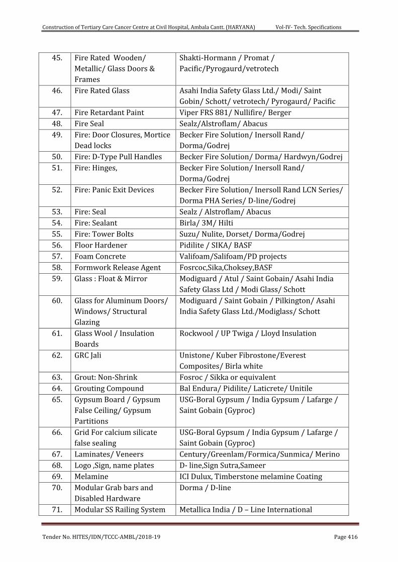
Construction of Tertiary Care Cancer Centre at Civil Hospital, Ambala Cantt. (HARYANA) Vol-IV- Tech. Specifications
Tender No. HITES/IDN/TCCC-AMBL/2018-19 Page 416
45. Fire Rated Wooden/
Metallic/ Glass Doors &
Frames
Shakti-Hormann / Promat /
Pacific/Pyrogaurd/vetrotech
46. Fire Rated Glass Asahi India Safety Glass Ltd./ Modi/ Saint
Gobin/ Schott/ vetrotech/ Pyrogaurd/ Pacific
47. Fire Retardant Paint Viper FRS 881/ Nullifire/ Berger
48. Fire Seal Sealz/Alstroflam/ Abacus
49. Fire: Door Closures, Mortice
Dead locks
Becker Fire Solution/ Inersoll Rand/
Dorma/Godrej
50. Fire: D-Type Pull Handles Becker Fire Solution/ Dorma/ Hardwyn/Godrej
51. Fire: Hinges, Becker Fire Solution/ Inersoll Rand/
Dorma/Godrej
52. Fire: Panic Exit Devices Becker Fire Solution/ Inersoll Rand LCN Series/
Dorma PHA Series/ D-line/Godrej
53. Fire: Seal Sealz / Alstroflam/ Abacus
54. Fire: Sealant Birla/ 3M/ Hilti
55. Fire: Tower Bolts Suzu/ Nulite, Dorset/ Dorma/Godrej
56. Floor Hardener Pidilite / SIKA/ BASF
57. Foam Concrete Valifoam/Salifoam/PD projects
58. Formwork Release Agent Fosrcoc,Sika,Choksey,BASF
59. Glass : Float & Mirror Modiguard / Atul / Saint Gobain/ Asahi India
Safety Glass Ltd / Modi Glass/ Schott
60. Glass for Aluminum Doors/
Windows/ Structural
Glazing
Modiguard / Saint Gobain / Pilkington/ Asahi
India Safety Glass Ltd./Modiglass/ Schott
61. Glass Wool / Insulation
Boards
Rockwool / UP Twiga / Lloyd Insulation
62. GRC Jali Unistone/ Kuber Fibrostone/Everest
Composites/ Birla white
63. Grout: Non-Shrink Fosroc / Sikka or equivalent
64. Grouting Compound Bal Endura/ Pidilite/ Laticrete/ Unitile
65. Gypsum Board / Gypsum
False Ceiling/ Gypsum
Partitions
USG-Boral Gypsum / India Gypsum / Lafarge /
Saint Gobain (Gyproc)
66. Grid For calcium silicate
false sealing
USG-Boral Gypsum / India Gypsum / Lafarge /
Saint Gobain (Gyproc)
67. Laminates/ Veneers Century/Greenlam/Formica/Sunmica/ Merino
68. Logo ,Sign, name plates D- line,Sign Sutra,Sameer
69. Melamine ICI Dulux, Timberstone melamine Coating
70. Modular Grab bars and
Disabled Hardware
Dorma / D-line
71. Modular SS Railing System Metallica India / D – Line International
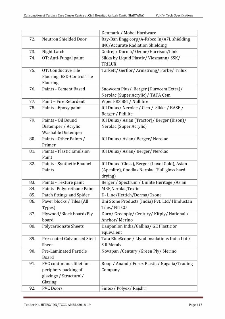
Construction of Tertiary Care Cancer Centre at Civil Hospital, Ambala Cantt. (HARYANA) Vol-IV- Tech. Specifications
Tender No. HITES/IDN/TCCC-AMBL/2018-19 Page 417
Denmark / Mobel Hardware
72. Neutron Shielded Door Ray-Ban Engg corp/A-Fabco In/A7L shielding
INC/Accurate Radiation Shielding
73. Night Latch Godrej / Dorma/ Ozone/Harrison/Link
74. OT: Anti-Fungal paint Sikka by Liquid Plastic/ Viesmann/ SSK/
TRILUX
75. OT: Conductive Tile
Flooring: ESD-Control Tile
Flooring
Tarkett/ Gerflor/ Armstrong/ Forbe/ Trilux
76. Paints - Cement Based Snowcem Plus/, Berger (Durocem Extra)/
Nerolac (Super Acrylic)/ TATA Cem
77. Paint – Fire Retardent Viper FRS 881/ Nullifire
78. Paints - Epoxy paint ICI Dulux/ Nerolac / Cico / Sikka / BASF /
Berger / Pidilite
79. Paints - Oil Bound
Distemper / Acrylic
Washable Distemper
ICI Dulux/ Asian (Tractor)/ Berger (Bison)/
Nerolac (Super Acrylic)
80. Paints - Other Paints /
Primer
ICI Dulux/ Asian/ Berger/ Nerolac
81. Paints - Plastic Emulsion
Paint
ICI Dulux/ Asian/ Berger/ Nerolac
82. Paints - Synthetic Enamel
Paints
ICI Dulux (Gloss), Berger (Luxol Gold), Asian
(Apcolite), Goodlas Nerolac (Full gloss hard
drying)
83. Paints - Texture paint Berger / Spectrum / Unilite Heritage /Asian
84. Paints- Polyurethane Paint MRF,Nerolac,Texfin
85. Patch fittings and Spider D- Line/Hettich/Dorma/Ozone
86. Paver blocks / Tiles (All
Types)
Uni Stone Products (India) Pvt. Ltd/ Hindustan
Tiles/ NITCO
87. Plywood/Block board/Ply
board
Duro/ Greenply/ Century/ Kitply/ National /
Anchor/ Merino
88. Polycarbonate Sheets Danpanlon India/Gallina/ GE Plastic or
equivalent
89. Pre-coated Galvanised Steel
Sheet
Tata BlueScope / Llyod Insulations India Ltd /
S.R.Metals
90. Pre-Laminated Particle
Board
Novapan /Century /Green Ply/ Merino
91. PVC continuous fillet for
periphery packing of
glazings / Structural/
Glazing
Roop / Anand / Forex Plastic/ Nagalia/Trading
Company
92. PVC Doors Sintex/ Polyex/ Rajshri
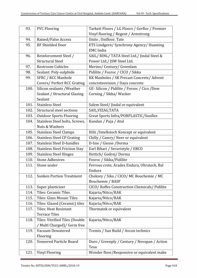
Construction of Tertiary Care Cancer Centre at Civil Hospital, Ambala Cantt. (HARYANA) Vol-IV- Tech. Specifications
Tender No. HITES/IDN/TCCC-AMBL/2018-19 Page 418
93. PVC Flooring Tarkett Floors / LG Floors / Gerflor / Premier
Vinyl flooring / Regent / Armstrong
94. Raised/False Access Unite , Unifloor, Tate
95. RF Shielded Door ETS Lindgern/ Synchrony Agency/ Huaming
EMC India
96. Reinforcement Steel /
Structural Steel
SAIL/ RINL/ TATA Steel Ltd./ Jindal Steel &
Power Ltd./ JSW Steel Ltd.
97. Restroom Cubicles Merino/ Century/ Greenlam
98. Sealant: Poly-sulphide Pidilite / Fosroc / CICO / Sikka
99. SFRC / RCC Manhole
Covers/ Perfect RCC Grating
KK Manholes / SK Precast Concrete/ Advent
concreteovision / Daya concrete
100. Silicon sealants /Weather
Sealant / Structural Glazing
Sealant
GE- Silicon / Pidilite / Forsoc / Cico /Dow
Corning / Sikka/ Wacker
101. Stainless Steel Salem Steel/ Jindal or equivalent
102. Structural steel sections SAIL,VIZAG,TATA
103. Outdoor Sports Flooring Great Sports Infra/PORPLASTIC/Sunflex
104. Stainless Steel bolts, Screws,
Nuts & Washers
Kundan / Puja / Atul
105. Stainless Steel Clamps Hilti /Intellotech Koncept or equivalent
106. Stainless Steel CP Grating Chilly / Camry/ Neer or equivalent
107. Stainless Steel D-handles D-line / Giesse /Dorma
108. Stainless Steel Friction Stay Earl Bihari / Securistyle / EBCO
109. Stainless Steel Hinges Hettich/ Godrej/ Dorma
110. Stone Adhesives Fosroc / Sikka/Pidilite
111. Stone sealer Ferrous crete, Aradex Endura, Ultratech, Bal
Endura
112. Sunken Portion Treatment Choksey / Sika / CICO/ MC Bouchemie / MC
Bouchemie / BASF
113. Super plasticizer CICO/ Roffes Construction Chemicals/ Pidilite
114. Tiles: Ceramic Tiles Kajaria/Nitco/RAK
115. Tiles: Glass Mosaic Tiles Kajaria/Nitco/RAK
116. Tiles: Glazed (Ceramic) tiles Kajaria/Nitco/RAK
117. Tiles: Heat Resistant
Terrace Tiles
Thermatek or equivalent
118. Tiles: Vitrified Tiles (Double
/ Multi Charged)/ Germ free
Kajaria/Nitco/RAK
119. Vacuum Dewatered
Flooring
Tremix / Sun Build / Avcon technics
120. Veneered Particle Board Duro / Greenply / Century / Novapan / Action
Tesa
121. Vinyl Flooring Wonder floor/Responsive or equivalent make
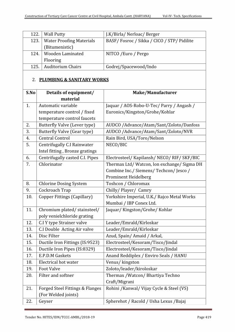
Construction of Tertiary Care Cancer Centre at Civil Hospital, Ambala Cantt. (HARYANA) Vol-IV- Tech. Specifications
Tender No. HITES/IDN/TCCC-AMBL/2018-19 Page 419
122. Wall Putty J.K/Birla/ Nerloac/ Berger
123. Water Proofing Materials
(Bitumenistic)
BASF/ Fosroc / Sikka / CICO / STP/ Pidilite
124. Wooden Laminated
Flooring
NITCO /Euro / Pergo
125. Auditorium Chairs Godrej/Spacewood/Indo
2. PLUMBING & SANITARY WORKS
S.No Details of equipment/
material
Make/Manufacturer
1. Automatic variable
temperature control / fixed
temperature control faucets
Jaquar / AOS-Robo-U-Tec/ Parry / Angash /
Euronics/Kingston/Grohe/Kohlar
2. Butterfly Valve (Lever type) AUDCO /Advance/Atam/Sant/Zoloto/Danfoss
3. Butterfly Valve (Gear type) AUDCO /Advance/Atam/Sant/Zoloto/NVR
4. Central Control Rain Bird, USA/Toro/Nelson
5. Centrifugally C.I Rainwater
Intel fitting , Bronze gratings
NECO/BIC
6. Centrifugally casted C.I. Pipes Electrosteel/ Kapilansh/ NECO/ RIF/ SKF/BIC
7. Chlorinator Thermax Ltd/ Watcon, lon exchange/ Sigma DH
Combine Inc./ Siemens/ Techcon/ Jesco /
Prominent Heidelberg
8. Chlorine Dosing System Toshcon / Chloromax
9. Cockroach Trap Chilly/ Player/ Camry
10. Copper Fittings (Capillary) Yorkshire Imperial, U.K./ Rajco Metal Works
Mumbai / IBP Conex Ltd.
11. Chromium plated/ stainsteel/
poly venielchloride grating
Jaquar/ Kingston/Grohe/ Kohlar
12. C.I Y type Strainer valve Leader/Emrald/Kirloskar
13. C.I Double Acting Air valve Leader/Emrald/Kirloskar
14. Disc Filter Azud, Spain/ Amaid / Arkal,
15. Ductile Iron Fittings (IS:9523) Electrosteel/Kesoram/Tisco/Jindal
16. Ductile Iron Pipes (IS:8329) Electrosteel/Kesoram/Tisco/Jindal
17. E.P.D.M Gaskets Anand Reddiplex / Enviro Seals / HANU
18. Electrical hot water Venus/ kingston
19. Foot Valve Zoloto/leader/kiroloskar
20. Filter and softner Thermax /Watcon/ Bhartiya Techno
Craft/Migrani
21. Forged Steel Fittings & Flanges
(For Welded joints)
Rohini /Kanwal/ Vijay Cycle & Steel (VS)
22. Geyser Spherehot / Racold / Usha Lexus /Bajaj
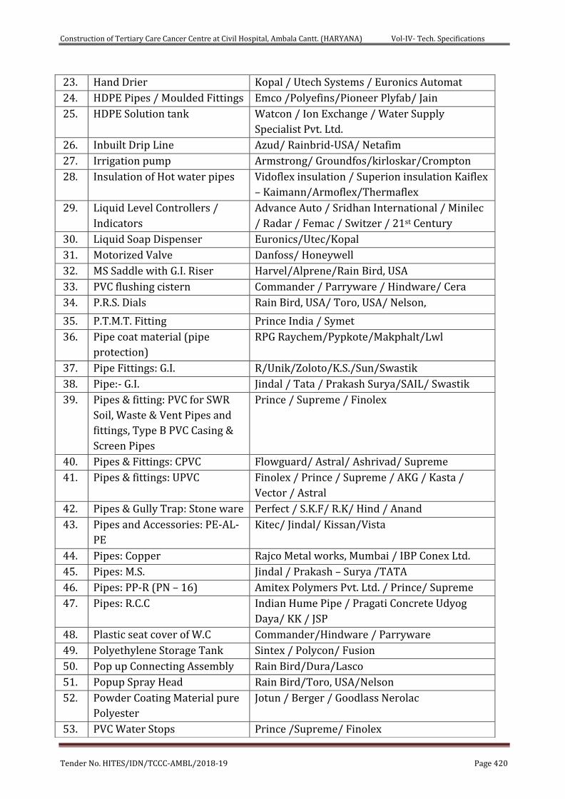
Construction of Tertiary Care Cancer Centre at Civil Hospital, Ambala Cantt. (HARYANA) Vol-IV- Tech. Specifications
Tender No. HITES/IDN/TCCC-AMBL/2018-19 Page 420
23. Hand Drier Kopal / Utech Systems / Euronics Automat
24. HDPE Pipes / Moulded Fittings Emco /Polyefins/Pioneer Plyfab/ Jain
25. HDPE Solution tank Watcon / Ion Exchange / Water Supply
Specialist Pvt. Ltd.
26. Inbuilt Drip Line Azud/ Rainbrid-USA/ Netafim
27. Irrigation pump Armstrong/ Groundfos/kirloskar/Crompton
28. Insulation of Hot water pipes Vidoflex insulation / Superion insulation Kaiflex
– Kaimann/Armoflex/Thermaflex
29. Liquid Level Controllers /
Indicators
Advance Auto / Sridhan International / Minilec
/ Radar / Femac / Switzer / 21st Century
30. Liquid Soap Dispenser Euronics/Utec/Kopal
31. Motorized Valve Danfoss/ Honeywell
32. MS Saddle with G.I. Riser Harvel/Alprene/Rain Bird, USA
33. PVC flushing cistern Commander / Parryware / Hindware/ Cera
34. P.R.S. Dials Rain Bird, USA/ Toro, USA/ Nelson,
35. P.T.M.T. Fitting Prince India / Symet
36. Pipe coat material (pipe
protection)
RPG Raychem/Pypkote/Makphalt/Lwl
37. Pipe Fittings: G.I. R/Unik/Zoloto/K.S./Sun/Swastik
38. Pipe:- G.I. Jindal / Tata / Prakash Surya/SAIL/ Swastik
39. Pipes & fitting: PVC for SWR
Soil, Waste & Vent Pipes and
fittings, Type B PVC Casing &
Screen Pipes
Prince / Supreme / Finolex
40. Pipes & Fittings: CPVC Flowguard/ Astral/ Ashrivad/ Supreme
41. Pipes & fittings: UPVC Finolex / Prince / Supreme / AKG / Kasta /
Vector / Astral
42. Pipes & Gully Trap: Stone ware Perfect / S.K.F/ R.K/ Hind / Anand
43. Pipes and Accessories: PE-AL-
PE
Kitec/ Jindal/ Kissan/Vista
44. Pipes: Copper Rajco Metal works, Mumbai / IBP Conex Ltd.
45. Pipes: M.S. Jindal / Prakash – Surya /TATA
46. Pipes: PP-R (PN – 16) Amitex Polymers Pvt. Ltd. / Prince/ Supreme
47. Pipes: R.C.C Indian Hume Pipe / Pragati Concrete Udyog
Daya/ KK / JSP
48. Plastic seat cover of W.C Commander/Hindware / Parryware
49. Polyethylene Storage Tank Sintex / Polycon/ Fusion
50. Pop up Connecting Assembly Rain Bird/Dura/Lasco
51. Popup Spray Head Rain Bird/Toro, USA/Nelson
52. Powder Coating Material pure
Polyester
Jotun / Berger / Goodlass Nerolac
53. PVC Water Stops Prince /Supreme/ Finolex
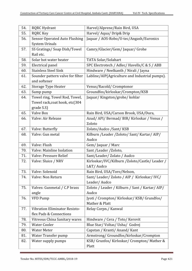
Construction of Tertiary Care Cancer Centre at Civil Hospital, Ambala Cantt. (HARYANA) Vol-IV- Tech. Specifications
Tender No. HITES/IDN/TCCC-AMBL/2018-19 Page 421
54. RQRC Hydrant Harvel/Alprene/Rain Bird, USA
55. RQRC Key Harvel/ Aqua/ Drip& Drip
56. Sensor Operated Auto Flushing
System Urinals
Jaquar / AOS-Robo/U-tec/Angash/Euronics
57. SS Gratings/ Soap Dish/Towel
Rail etc.
Camry/Glacier/Gem/ Jaquar/ Grohe
58. Solar hot water heater TATA Solar/Solahart
59. Electrical panel SPC Electrotech / Adlec/ Havells/C & S / ABB
60. Stainless Steel Sink Hindware / Neelkanth / Nirali / Jayna
61. Sounder pattern valve for filter
and softener
Labline/AIP(Agriculture and Industrial pumps).
62. Storage Type Heater Venus/Racold/ Cromptonor
63. Sump pump Groundfos/kirloskar/Crompton/KSB
64. Towel ring, Towel Rod, Towel,
Towel rack,coat hook, etc(304
grade S.S)
Jaquar/ Kingston/grohe/ kohlar
65. Valve Box Rain Bird, USA/Carson Brook, USA/Dura,
66. Valve: Air Release Azud/ API/ Bermad/ BIR/ Kirloskar / Venus /
Zoloto
67. Valve: Butterfly Zolato/Audco /Sant/ KSB
68. Valve: Gun metal Kilburn /Leader /Zoloto/ Sant/ Kartar/ AIP/
Audco
69. Valve: Flush Gem/ Jaquar / Marc
70. Valve: Mainline Isolation Sant /Leader /Zoloto,
71. Valve: Pressure Relief Sant/Leader/ Zolato / Audco
72. Valve: Sluice / NRV Kirloskar/IVC/Kilburn /Zoloto/Castle/ Leader /
L&T/ Audco
73. Valve: Solenoid Rain Bird, USA/Toro/Nelson,
74. Valve: Non Return Sant/ Leader/ Zoloto / AIP / Kirloskar/ IVC/
Leader/ Audco
75. Valves: Gunmetal / C.P brass
angle
Zoloto / Leader / Kilburn / Sant / Kartar/ AIP/
Audco
76. VFD Pump Jyoti / Crompton/ Kirloskar/ KSB/ Grundfos/
Mather & Platt
77. Vibration Eliminator Resisto-
flex Pads & Connections
Relay Corpn./ Kanwal
78. Vitreous China Sanitary wares Hindware / Cera / Toto/ Kerovit
79. Water Cooler Blue Star/ Voltas/ Usha/ Godrej
80. Water Meter Capstan / Kranti/ Anand/ Kant
81. Water Transfer pump Armstrong/ Groundfos/kirloskar/Crompton
82. Water supply pumps KSB/ Grunfos/ Kirloskar/ Crompton/ Mather &
Platt
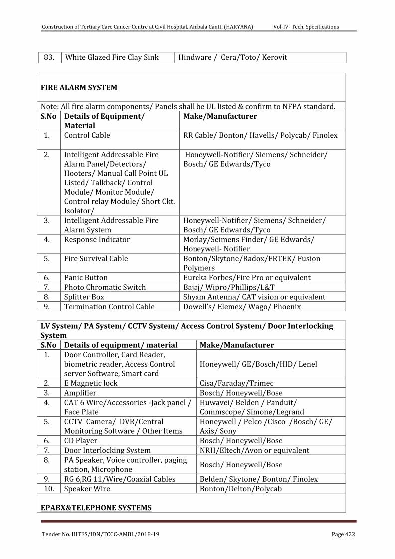
Construction of Tertiary Care Cancer Centre at Civil Hospital, Ambala Cantt. (HARYANA) Vol-IV- Tech. Specifications
Tender No. HITES/IDN/TCCC-AMBL/2018-19 Page 422
FIRE ALARM SYSTEM Note: All fire alarm components/ Panels shall be UL listed & confirm to NFPA standard. S.No Details of Equipment/
Material Make/Manufacturer
1. Control Cable RR Cable/ Bonton/ Havells/ Polycab/ Finolex
2. Intelligent Addressable Fire Alarm Panel/Detectors/ Hooters/ Manual Call Point UL Listed/ Talkback/ Control Module/ Monitor Module/ Control relay Module/ Short Ckt. Isolator/
Honeywell-Notifier/ Siemens/ Schneider/ Bosch/ GE Edwards/Tyco
3. Intelligent Addressable Fire Alarm System
Honeywell-Notifier/ Siemens/ Schneider/ Bosch/ GE Edwards/Tyco
4. Response Indicator Morlay/Seimens Finder/ GE Edwards/ Honeywell- Notifier
5. Fire Survival Cable Bonton/Skytone/Radox/FRTEK/ Fusion Polymers
6. Panic Button Eureka Forbes/Fire Pro or equivalent 7. Photo Chromatic Switch Bajaj/ Wipro/Phillips/L&T 8. Splitter Box Shyam Antenna/ CAT vision or equivalent 9. Termination Control Cable Dowell’s/ Elemex/ Wago/ Phoenix
LV System/ PA System/ CCTV System/ Access Control System/ Door Interlocking System S.No Details of equipment/ material Make/Manufacturer 1. Door Controller, Card Reader,
biometric reader, Access Control server Software, Smart card
Honeywell/ GE/Bosch/HID/ Lenel
2. E Magnetic lock Cisa/Faraday/Trimec 3. Amplifier Bosch/ Honeywell/Bose 4. CAT 6 Wire/Accessories -Jack panel /
Face Plate Huwavei/ Belden / Panduit/ Commscope/ Simone/Legrand
5. CCTV Camera/ DVR/Central Monitoring Software / Other Items
Honeywell / Pelco /Cisco /Bosch/ GE/ Axis/ Sony
6. CD Player Bosch/ Honeywell/Bose 7. Door Interlocking System NRH/Eltech/Avon or equivalent 8. PA Speaker, Voice controller, paging
station, Microphone Bosch/ Honeywell/Bose
9. RG 6,RG 11/Wire/Coaxial Cables Belden/ Skytone/ Bonton/ Finolex 10. Speaker Wire Bonton/Delton/Polycab
EPABX&TELEPHONE SYSTEMS
83. White Glazed Fire Clay Sink Hindware / Cera/Toto/ Kerovit
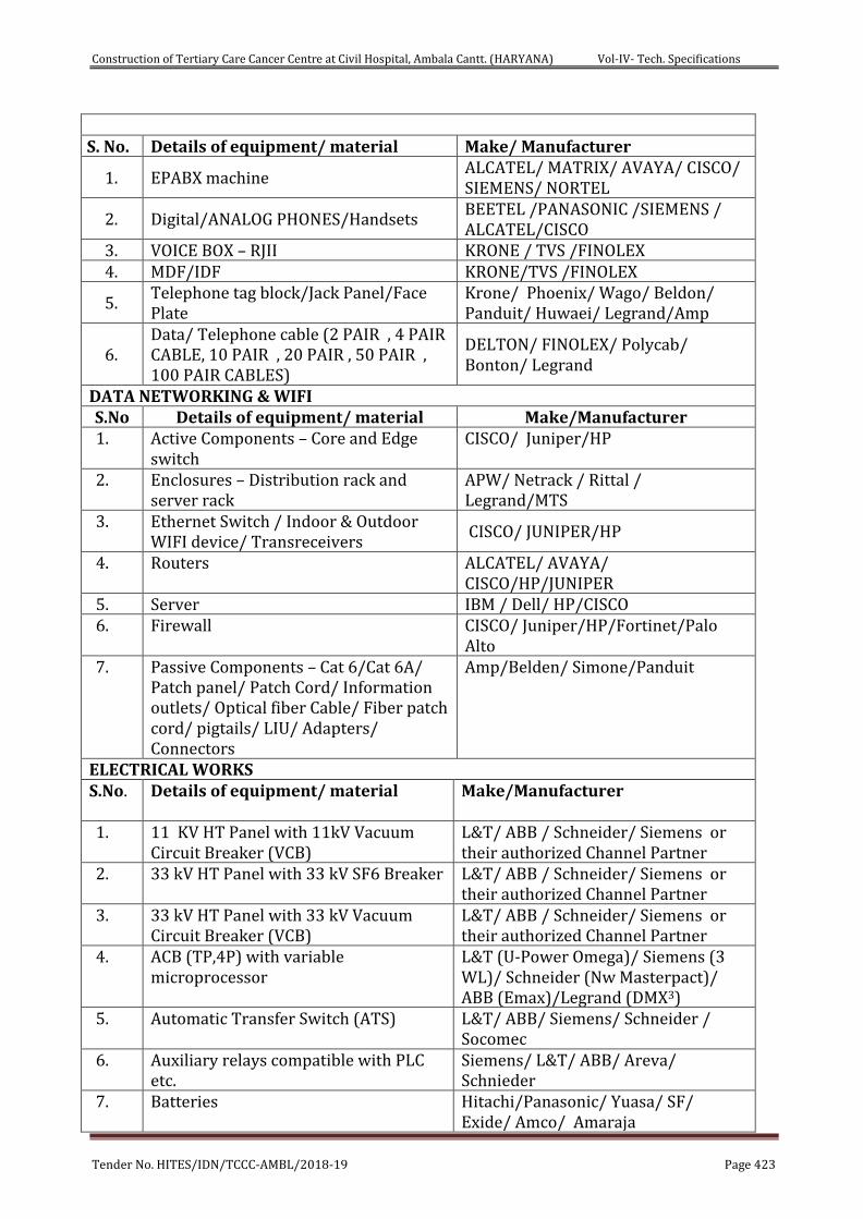
Construction of Tertiary Care Cancer Centre at Civil Hospital, Ambala Cantt. (HARYANA) Vol-IV- Tech. Specifications
Tender No. HITES/IDN/TCCC-AMBL/2018-19 Page 423
S. No. Details of equipment/ material Make/ Manufacturer
1. EPABX machine ALCATEL/ MATRIX/ AVAYA/ CISCO/ SIEMENS/ NORTEL
2. Digital/ANALOG PHONES/Handsets BEETEL /PANASONIC /SIEMENS / ALCATEL/CISCO
3. VOICE BOX – RJII KRONE / TVS /FINOLEX 4. MDF/IDF KRONE/TVS /FINOLEX
5. Telephone tag block/Jack Panel/Face Plate
Krone/ Phoenix/ Wago/ Beldon/ Panduit/ Huwaei/ Legrand/Amp
6. Data/ Telephone cable (2 PAIR , 4 PAIR CABLE, 10 PAIR , 20 PAIR , 50 PAIR , 100 PAIR CABLES)
DELTON/ FINOLEX/ Polycab/ Bonton/ Legrand
DATA NETWORKING & WIFI S.No Details of equipment/ material Make/Manufacturer 1. Active Components – Core and Edge
switch CISCO/ Juniper/HP
2. Enclosures – Distribution rack and server rack
APW/ Netrack / Rittal / Legrand/MTS
3. Ethernet Switch / Indoor & Outdoor WIFI device/ Transreceivers
CISCO/ JUNIPER/HP
4. Routers ALCATEL/ AVAYA/ CISCO/HP/JUNIPER
5. Server IBM / Dell/ HP/CISCO 6. Firewall CISCO/ Juniper/HP/Fortinet/Palo
Alto 7. Passive Components – Cat 6/Cat 6A/
Patch panel/ Patch Cord/ Information outlets/ Optical fiber Cable/ Fiber patch cord/ pigtails/ LIU/ Adapters/ Connectors
Amp/Belden/ Simone/Panduit
ELECTRICAL WORKS S.No. Details of equipment/ material
Make/Manufacturer
1. 11 KV HT Panel with 11kV Vacuum Circuit Breaker (VCB)
L&T/ ABB / Schneider/ Siemens or their authorized Channel Partner
2. 33 kV HT Panel with 33 kV SF6 Breaker L&T/ ABB / Schneider/ Siemens or their authorized Channel Partner
3. 33 kV HT Panel with 33 kV Vacuum Circuit Breaker (VCB)
L&T/ ABB / Schneider/ Siemens or their authorized Channel Partner
4. ACB (TP,4P) with variable microprocessor
L&T (U-Power Omega)/ Siemens (3 WL)/ Schneider (Nw Masterpact)/ ABB (Emax)/Legrand (DMX3)
5. Automatic Transfer Switch (ATS) L&T/ ABB/ Siemens/ Schneider / Socomec
6. Auxiliary relays compatible with PLC etc.
Siemens/ L&T/ ABB/ Areva/ Schnieder
7. Batteries Hitachi/Panasonic/ Yuasa/ SF/ Exide/ Amco/ Amaraja
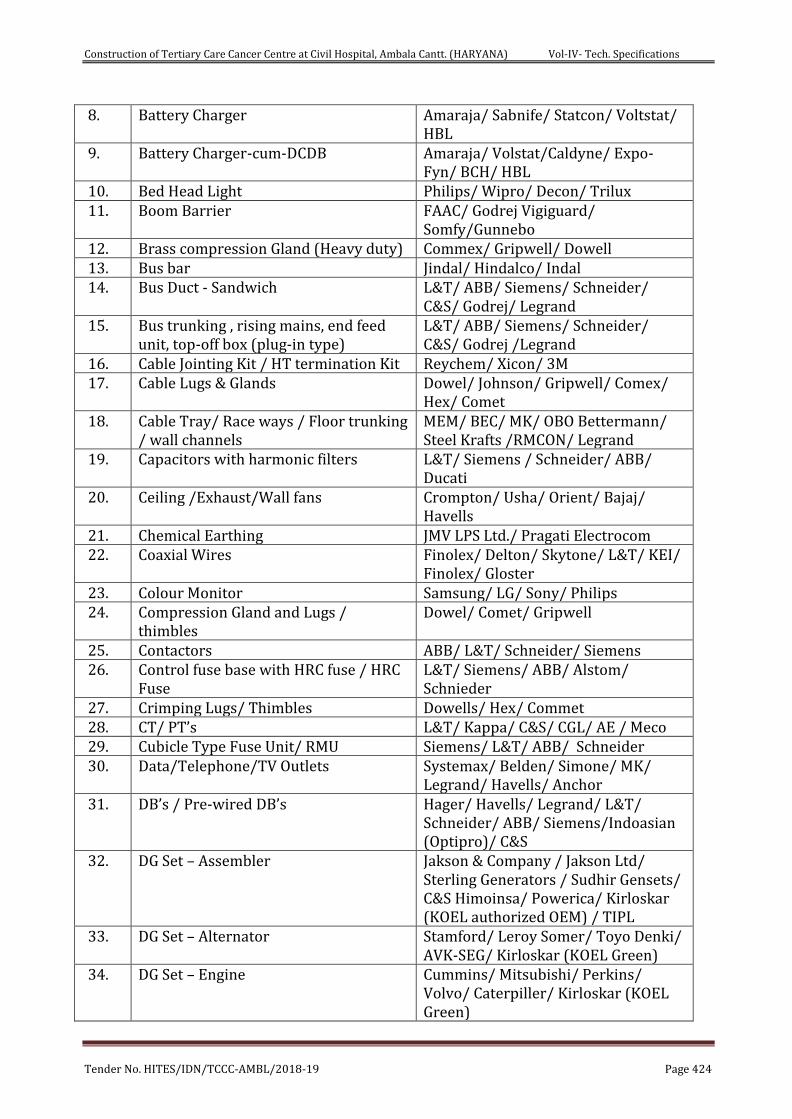
Construction of Tertiary Care Cancer Centre at Civil Hospital, Ambala Cantt. (HARYANA) Vol-IV- Tech. Specifications
Tender No. HITES/IDN/TCCC-AMBL/2018-19 Page 424
8. Battery Charger Amaraja/ Sabnife/ Statcon/ Voltstat/ HBL
9. Battery Charger-cum-DCDB Amaraja/ Volstat/Caldyne/ Expo-Fyn/ BCH/ HBL
10. Bed Head Light Philips/ Wipro/ Decon/ Trilux 11. Boom Barrier FAAC/ Godrej Vigiguard/
Somfy/Gunnebo 12. Brass compression Gland (Heavy duty) Commex/ Gripwell/ Dowell 13. Bus bar Jindal/ Hindalco/ Indal 14. Bus Duct - Sandwich L&T/ ABB/ Siemens/ Schneider/
C&S/ Godrej/ Legrand 15. Bus trunking , rising mains, end feed
unit, top-off box (plug-in type) L&T/ ABB/ Siemens/ Schneider/ C&S/ Godrej /Legrand
16. Cable Jointing Kit / HT termination Kit Reychem/ Xicon/ 3M 17. Cable Lugs & Glands Dowel/ Johnson/ Gripwell/ Comex/
Hex/ Comet 18. Cable Tray/ Race ways / Floor trunking
/ wall channels MEM/ BEC/ MK/ OBO Bettermann/ Steel Krafts /RMCON/ Legrand
19. Capacitors with harmonic filters L&T/ Siemens / Schneider/ ABB/ Ducati
20. Ceiling /Exhaust/Wall fans Crompton/ Usha/ Orient/ Bajaj/ Havells
21. Chemical Earthing JMV LPS Ltd./ Pragati Electrocom 22. Coaxial Wires Finolex/ Delton/ Skytone/ L&T/ KEI/
Finolex/ Gloster 23. Colour Monitor Samsung/ LG/ Sony/ Philips 24. Compression Gland and Lugs /
thimbles Dowel/ Comet/ Gripwell
25. Contactors ABB/ L&T/ Schneider/ Siemens 26. Control fuse base with HRC fuse / HRC
Fuse L&T/ Siemens/ ABB/ Alstom/ Schnieder
27. Crimping Lugs/ Thimbles Dowells/ Hex/ Commet 28. CT/ PT’s L&T/ Kappa/ C&S/ CGL/ AE / Meco 29. Cubicle Type Fuse Unit/ RMU Siemens/ L&T/ ABB/ Schneider 30. Data/Telephone/TV Outlets Systemax/ Belden/ Simone/ MK/
Legrand/ Havells/ Anchor 31. DB’s / Pre-wired DB’s Hager/ Havells/ Legrand/ L&T/
Schneider/ ABB/ Siemens/Indoasian (Optipro)/ C&S
32. DG Set – Assembler Jakson & Company / Jakson Ltd/ Sterling Generators / Sudhir Gensets/ C&S Himoinsa/ Powerica/ Kirloskar (KOEL authorized OEM) / TIPL
33. DG Set – Alternator Stamford/ Leroy Somer/ Toyo Denki/ AVK-SEG/ Kirloskar (KOEL Green)
34. DG Set – Engine Cummins/ Mitsubishi/ Perkins/ Volvo/ Caterpiller/ Kirloskar (KOEL Green)

Construction of Tertiary Care Cancer Centre at Civil Hospital, Ambala Cantt. (HARYANA) Vol-IV- Tech. Specifications
Tender No. HITES/IDN/TCCC-AMBL/2018-19 Page 425
35. DG Synchronizing Controller Woodword/ Dief/ Deep sea 36. Digital Lighting Control System Wipro/ Siemens/ Philips/ Schneider/
ABB/ L&T 37. Digital Numerical Relays L&T/ ABB / Siemens/ Schneider/
Areva 38. DWC HDPE Pipe DURA-LINE / REX / CARLON/
EMTELLE 39. Digital Energy Meters including Dual
Source Energy Meters L&T/ Rishabh/ Schneider/ HPL/ Siemens/ ABB/ Socomec/ Neptune
40. Electrical Motors L&T/ ABB/ Siemens/ Kirloskar 41. Optical Fiber Cable Sterlite Technologies/ Finolex/
Belden/ Delton/ Skytone 42. Fire Extinguisher Ceasefire/ Exflame/ Minimax/ Life
Guard/ Safex 43. Fire Survival Cables KEI/ Polycab/ Havells/ Fusion
Polymers 44. PVC insulated FRLS - Aluminum /
Copper 1.1 KV grade flexible wires L&T/ Gloster/ Havells/ Polycab / Finolex/ RR Kable/ KEI/ Batra henlay
45. G.I./Cu. Strip & earthing material Bharati/ Indiana/ Slotco 46. Hand Gloves & Rubber Mat Premier Polyfim Ltd/ Polyelectrosafe/
Challenger/ Electromat/ Safe Hold 47. HRC Fuse Siemens/ L&T/ ABB/ Schneider 48. HT & LT Cables (Power & Control) Gloster/ Havells/ Nicco/ Finolex/ KEI 49. Indicating Lamps AE/ Kaycee/ Vaishnav/ L&T/
Siemens/ Schnieder/ Teknik/ ABB 50. Industrial Socket Outlets ABB/ L&T/ Legrand/ Siemens/ Hager 51. Insulated Rubber Mat Premier Polyfilm Ltd/
Polyelectrosafe/ Challenger/ Electro Mat/ Safe Hold
52. Insulators Jaya Shree/ Modern/ IEC/ WSI 53. Intelligent Detectors/ Hooters &
accessories Notifier/ Honeywell/ Schneider/ Edwards/ Siemens/ L&T
54. Intelligent Fire Alarm Panel Notifier/ Honeywell/ Schneider/ Edwards/ Siemens/ L&T
55. Inverter Microtek / Luminous / Su-Kam/ Eaton
56. Isolators Siemens/ L&T/ ABB/ C&S/ Socomec/ Schnieder
57. Jointing Kit Reychem/ Xicon/ Birla-3M 58. LED Light Fixtures and Lamps Philips/ Wipro/ Keselec-Shreder/
Trilux/ C&S 59. Lightening Arrestors L&P ELECTRO/ LPI/ Indelec 60. LT Panels / Synchronizing Panel/
Capacitor Panel L&T/ ABB / Schneider/ Siemens/ Legrand or their authorized Channel Partners
61. MCBs / RCCB/Isolaters / RCBO / Change over switch
Hager/ Havells/ Legrand/ L&T/ Schneider/ ABB/ Siemens/Indoasian (Optipro)/ C&S
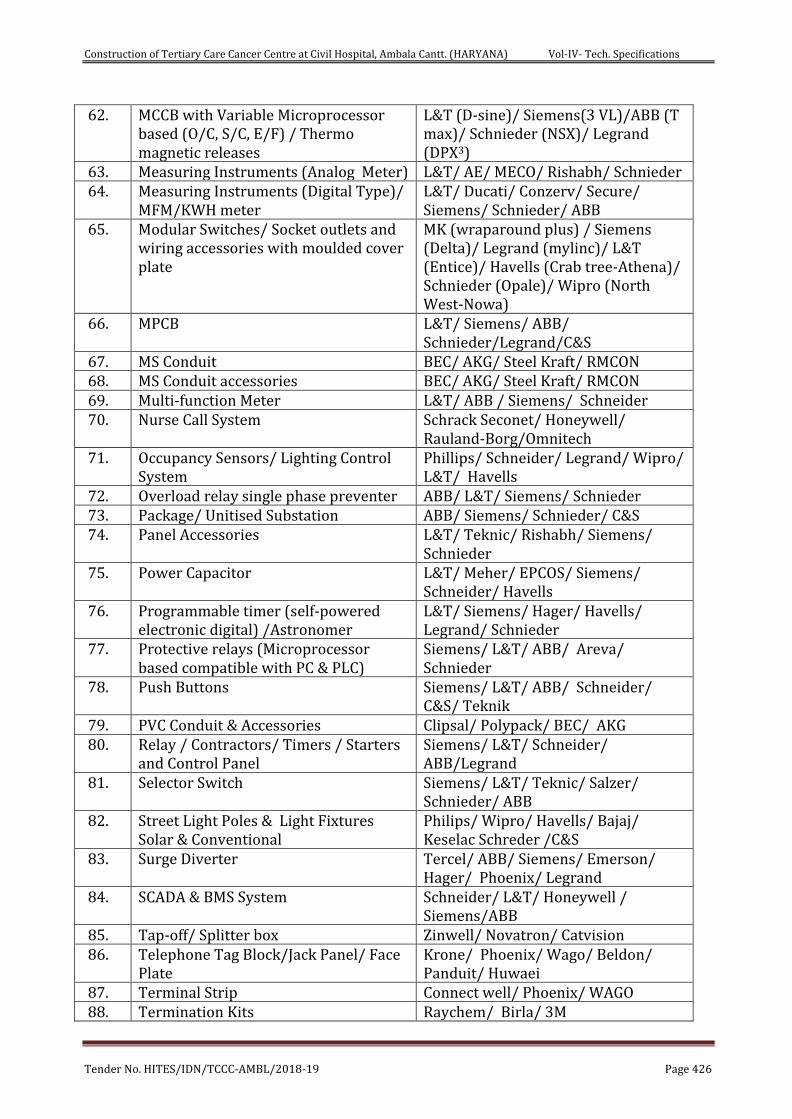
Construction of Tertiary Care Cancer Centre at Civil Hospital, Ambala Cantt. (HARYANA) Vol-IV- Tech. Specifications
Tender No. HITES/IDN/TCCC-AMBL/2018-19 Page 426
62. MCCB with Variable Microprocessor based (O/C, S/C, E/F) / Thermo magnetic releases
L&T (D-sine)/ Siemens(3 VL)/ABB (T max)/ Schnieder (NSX)/ Legrand (DPX3)
63. Measuring Instruments (Analog Meter) L&T/ AE/ MECO/ Rishabh/ Schnieder 64. Measuring Instruments (Digital Type)/
MFM/KWH meter L&T/ Ducati/ Conzerv/ Secure/ Siemens/ Schnieder/ ABB
65. Modular Switches/ Socket outlets and wiring accessories with moulded cover plate
MK (wraparound plus) / Siemens (Delta)/ Legrand (mylinc)/ L&T (Entice)/ Havells (Crab tree-Athena)/ Schnieder (Opale)/ Wipro (North West-Nowa)
66. MPCB L&T/ Siemens/ ABB/ Schnieder/Legrand/C&S
67. MS Conduit BEC/ AKG/ Steel Kraft/ RMCON 68. MS Conduit accessories BEC/ AKG/ Steel Kraft/ RMCON 69. Multi-function Meter L&T/ ABB / Siemens/ Schneider 70. Nurse Call System Schrack Seconet/ Honeywell/
Rauland-Borg/Omnitech 71. Occupancy Sensors/ Lighting Control
System Phillips/ Schneider/ Legrand/ Wipro/ L&T/ Havells
72. Overload relay single phase preventer ABB/ L&T/ Siemens/ Schnieder 73. Package/ Unitised Substation ABB/ Siemens/ Schnieder/ C&S 74. Panel Accessories L&T/ Teknic/ Rishabh/ Siemens/
Schnieder 75. Power Capacitor L&T/ Meher/ EPCOS/ Siemens/
Schneider/ Havells 76. Programmable timer (self-powered
electronic digital) /Astronomer L&T/ Siemens/ Hager/ Havells/ Legrand/ Schnieder
77. Protective relays (Microprocessor based compatible with PC & PLC)
Siemens/ L&T/ ABB/ Areva/ Schnieder
78. Push Buttons
Siemens/ L&T/ ABB/ Schneider/ C&S/ Teknik
79. PVC Conduit & Accessories Clipsal/ Polypack/ BEC/ AKG 80. Relay / Contractors/ Timers / Starters
and Control Panel Siemens/ L&T/ Schneider/ ABB/Legrand
81. Selector Switch Siemens/ L&T/ Teknic/ Salzer/ Schnieder/ ABB
82. Street Light Poles & Light Fixtures Solar & Conventional
Philips/ Wipro/ Havells/ Bajaj/ Keselac Schreder /C&S
83. Surge Diverter Tercel/ ABB/ Siemens/ Emerson/ Hager/ Phoenix/ Legrand
84. SCADA & BMS System Schneider/ L&T/ Honeywell / Siemens/ABB
85. Tap-off/ Splitter box Zinwell/ Novatron/ Catvision 86. Telephone Tag Block/Jack Panel/ Face
Plate Krone/ Phoenix/ Wago/ Beldon/ Panduit/ Huwaei
87. Terminal Strip Connect well/ Phoenix/ WAGO 88. Termination Kits Raychem/ Birla/ 3M
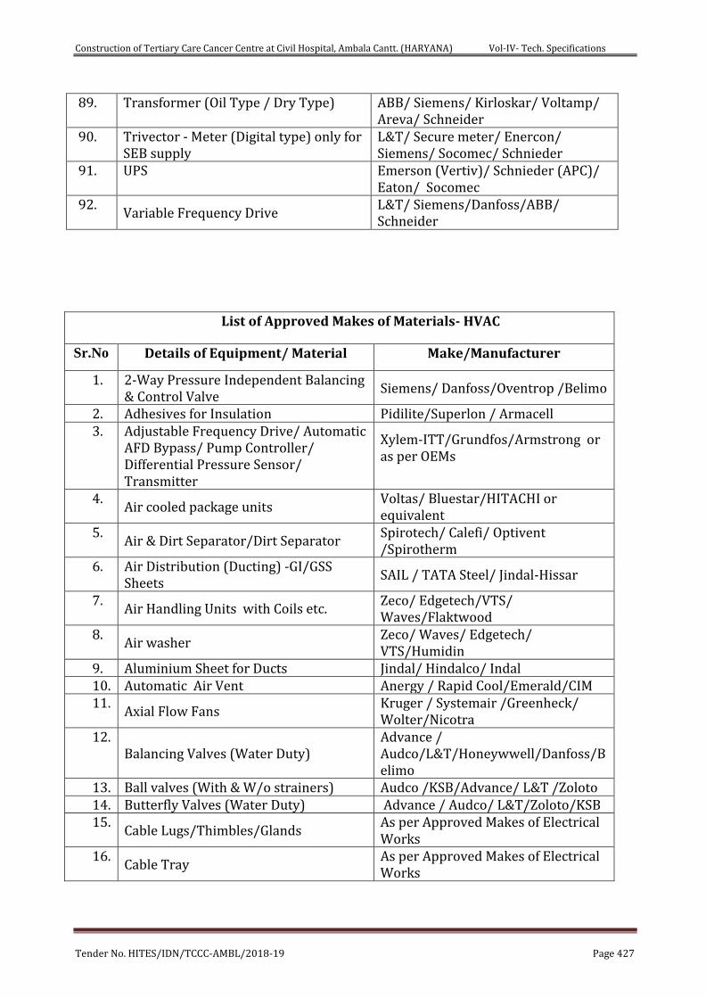
Construction of Tertiary Care Cancer Centre at Civil Hospital, Ambala Cantt. (HARYANA) Vol-IV- Tech. Specifications
Tender No. HITES/IDN/TCCC-AMBL/2018-19 Page 427
89. Transformer (Oil Type / Dry Type) ABB/ Siemens/ Kirloskar/ Voltamp/ Areva/ Schneider
90. Trivector - Meter (Digital type) only for SEB supply
L&T/ Secure meter/ Enercon/ Siemens/ Socomec/ Schnieder
91. UPS Emerson (Vertiv)/ Schnieder (APC)/ Eaton/ Socomec
92. Variable Frequency Drive
L&T/ Siemens/Danfoss/ABB/ Schneider
List of Approved Makes of Materials- HVAC
Sr.No Details of Equipment/ Material Make/Manufacturer
1. 2-Way Pressure Independent Balancing & Control Valve
Siemens/ Danfoss/Oventrop /Belimo
2. Adhesives for Insulation Pidilite/Superlon / Armacell 3. Adjustable Frequency Drive/ Automatic
AFD Bypass/ Pump Controller/ Differential Pressure Sensor/ Transmitter
Xylem-ITT/Grundfos/Armstrong or as per OEMs
4. Air cooled package units
Voltas/ Bluestar/HITACHI or equivalent
5. Air & Dirt Separator/Dirt Separator
Spirotech/ Calefi/ Optivent /Spirotherm
6. Air Distribution (Ducting) -GI/GSS Sheets
SAIL / TATA Steel/ Jindal-Hissar
7. Air Handling Units with Coils etc.
Zeco/ Edgetech/VTS/ Waves/Flaktwood
8. Air washer
Zeco/ Waves/ Edgetech/ VTS/Humidin
9. Aluminium Sheet for Ducts Jindal/ Hindalco/ Indal 10. Automatic Air Vent Anergy / Rapid Cool/Emerald/CIM 11.
Axial Flow Fans Kruger / Systemair /Greenheck/ Wolter/Nicotra
12. Balancing Valves (Water Duty)
Advance / Audco/L&T/Honeywwell/Danfoss/Belimo
13. Ball valves (With & W/o strainers) Audco /KSB/Advance/ L&T /Zoloto 14. Butterfly Valves (Water Duty) Advance / Audco/ L&T/Zoloto/KSB 15.
Cable Lugs/Thimbles/Glands As per Approved Makes of Electrical Works
16. Cable Tray
As per Approved Makes of Electrical Works
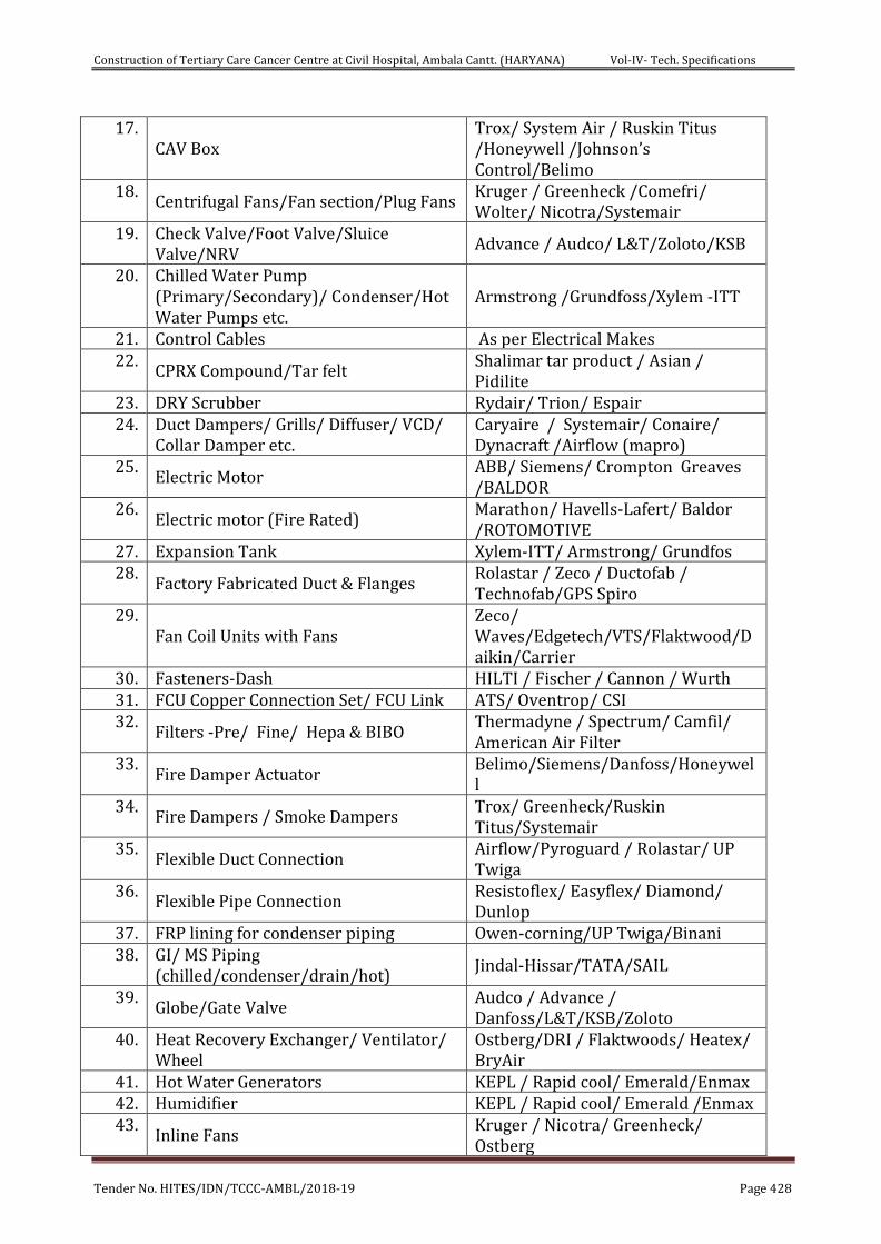
Construction of Tertiary Care Cancer Centre at Civil Hospital, Ambala Cantt. (HARYANA) Vol-IV- Tech. Specifications
Tender No. HITES/IDN/TCCC-AMBL/2018-19 Page 428
17. CAV Box
Trox/ System Air / Ruskin Titus /Honeywell /Johnson’s Control/Belimo
18. Centrifugal Fans/Fan section/Plug Fans
Kruger / Greenheck /Comefri/ Wolter/ Nicotra/Systemair
19. Check Valve/Foot Valve/Sluice Valve/NRV
Advance / Audco/ L&T/Zoloto/KSB
20. Chilled Water Pump (Primary/Secondary)/ Condenser/Hot Water Pumps etc.
Armstrong /Grundfoss/Xylem -ITT
21. Control Cables As per Electrical Makes 22.
CPRX Compound/Tar felt Shalimar tar product / Asian / Pidilite
23. DRY Scrubber Rydair/ Trion/ Espair 24. Duct Dampers/ Grills/ Diffuser/ VCD/
Collar Damper etc. Caryaire / Systemair/ Conaire/ Dynacraft /Airflow (mapro)
25. Electric Motor
ABB/ Siemens/ Crompton Greaves /BALDOR
26. Electric motor (Fire Rated)
Marathon/ Havells-Lafert/ Baldor /ROTOMOTIVE
27. Expansion Tank Xylem-ITT/ Armstrong/ Grundfos 28.
Factory Fabricated Duct & Flanges Rolastar / Zeco / Ductofab / Technofab/GPS Spiro
29. Fan Coil Units with Fans
Zeco/ Waves/Edgetech/VTS/Flaktwood/Daikin/Carrier
30. Fasteners-Dash HILTI / Fischer / Cannon / Wurth 31. FCU Copper Connection Set/ FCU Link ATS/ Oventrop/ CSI 32.
Filters -Pre/ Fine/ Hepa & BIBO Thermadyne / Spectrum/ Camfil/ American Air Filter
33. Fire Damper Actuator
Belimo/Siemens/Danfoss/Honeywell
34. Fire Dampers / Smoke Dampers
Trox/ Greenheck/Ruskin Titus/Systemair
35. Flexible Duct Connection
Airflow/Pyroguard / Rolastar/ UP Twiga
36. Flexible Pipe Connection
Resistoflex/ Easyflex/ Diamond/ Dunlop
37. FRP lining for condenser piping Owen-corning/UP Twiga/Binani 38. GI/ MS Piping
(chilled/condenser/drain/hot) Jindal-Hissar/TATA/SAIL
39. Globe/Gate Valve
Audco / Advance / Danfoss/L&T/KSB/Zoloto
40. Heat Recovery Exchanger/ Ventilator/ Wheel
Ostberg/DRI / Flaktwoods/ Heatex/ BryAir
41. Hot Water Generators KEPL / Rapid cool/ Emerald/Enmax 42. Humidifier KEPL / Rapid cool/ Emerald /Enmax 43.
Inline Fans Kruger / Nicotra/ Greenheck/ Ostberg
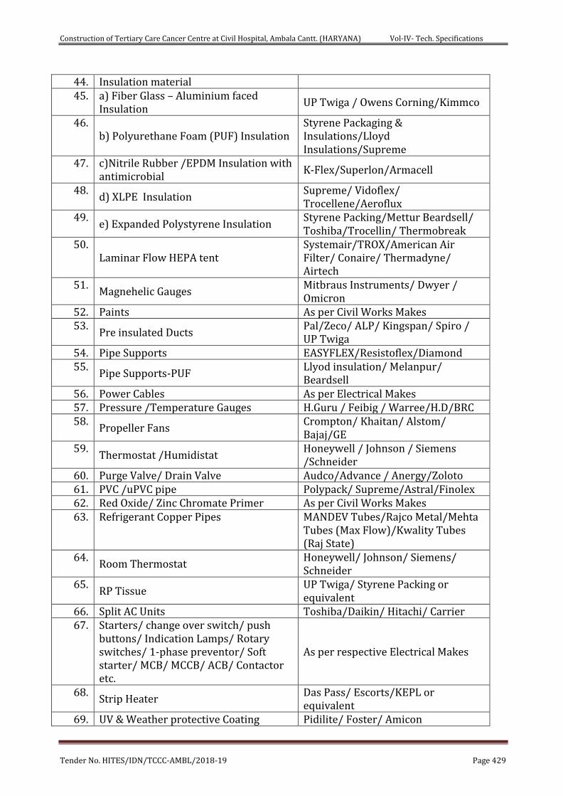
Construction of Tertiary Care Cancer Centre at Civil Hospital, Ambala Cantt. (HARYANA) Vol-IV- Tech. Specifications
Tender No. HITES/IDN/TCCC-AMBL/2018-19 Page 429
44. Insulation material 45. a) Fiber Glass – Aluminium faced
Insulation UP Twiga / Owens Corning/Kimmco
46. b) Polyurethane Foam (PUF) Insulation
Styrene Packaging & Insulations/Lloyd Insulations/Supreme
47. c)Nitrile Rubber /EPDM Insulation with antimicrobial
K-Flex/Superlon/Armacell
48. d) XLPE Insulation
Supreme/ Vidoflex/ Trocellene/Aeroflux
49. e) Expanded Polystyrene Insulation
Styrene Packing/Mettur Beardsell/ Toshiba/Trocellin/ Thermobreak
50. Laminar Flow HEPA tent
Systemair/TROX/American Air Filter/ Conaire/ Thermadyne/ Airtech
51. Magnehelic Gauges
Mitbraus Instruments/ Dwyer / Omicron
52. Paints As per Civil Works Makes 53.
Pre insulated Ducts Pal/Zeco/ ALP/ Kingspan/ Spiro / UP Twiga
54. Pipe Supports EASYFLEX/Resistoflex/Diamond 55.
Pipe Supports-PUF Llyod insulation/ Melanpur/ Beardsell
56. Power Cables As per Electrical Makes 57. Pressure /Temperature Gauges H.Guru / Feibig / Warree/H.D/BRC 58.
Propeller Fans Crompton/ Khaitan/ Alstom/ Bajaj/GE
59. Thermostat /Humidistat
Honeywell / Johnson / Siemens /Schneider
60. Purge Valve/ Drain Valve Audco/Advance / Anergy/Zoloto 61. PVC /uPVC pipe Polypack/ Supreme/Astral/Finolex 62. Red Oxide/ Zinc Chromate Primer As per Civil Works Makes 63. Refrigerant Copper Pipes MANDEV Tubes/Rajco Metal/Mehta
Tubes (Max Flow)/Kwality Tubes (Raj State)
64. Room Thermostat
Honeywell/ Johnson/ Siemens/ Schneider
65. RP Tissue
UP Twiga/ Styrene Packing or equivalent
66. Split AC Units Toshiba/Daikin/ Hitachi/ Carrier 67. Starters/ change over switch/ push
buttons/ Indication Lamps/ Rotary switches/ 1-phase preventor/ Soft starter/ MCB/ MCCB/ ACB/ Contactor etc.
As per respective Electrical Makes
68. Strip Heater
Das Pass/ Escorts/KEPL or equivalent
69. UV & Weather protective Coating Pidilite/ Foster/ Amicon
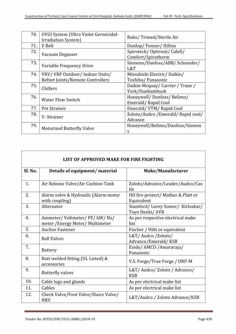
Construction of Tertiary Care Cancer Centre at Civil Hospital, Ambala Cantt. (HARYANA) Vol-IV- Tech. Specifications
Tender No. HITES/IDN/TCCC-AMBL/2018-19 Page 430
70. UVGI System (Ultra Violet Germicidal- Irradiation System)
Ruks/ Trimed/Sterile Air
71. V Belt Dunlop/ Fenner/ Hilton 72.
Vacuum Degasser Spirotech/ Optivent/ Calefi/ Comfort/Spirotherm
73. Variable Frequency Drive
Siemens/Danfoss/ABB/ Schneider/ L&T
74. VRV/ VRF Outdoor/ Indoor Units/ Refnet Joints/Remote Controllers
Mitsubishi Electric/ Daikin/ Toshiba/ Panasonic
75. Chillers
Daikin-Mcquay/ Carrier / Trane / York/Dunhambush
76. Water Flow Switch
Honeywell/ Danfoss/ Belimo/ Emerald/ Rapid Cool
77. Pot Strainer Emerald/ VTM/ Rapid Cool 78.
Y- Strainer Zoloto/Audco /Emerald/ Rapid cool/ Advance
79. Motorized Butterfly Valve
Honeywell/Belimo/Danfoss/Siemens
LIST OF APPROVED MAKE FOR FIRE FIGHTING
Sl. No. Details of equipment/ material Make/Manufacturer
1. Air Release Valve/Air Cushion Tank Zoloto/Advance/Leader/Audco/Castle
2. Alarm valve & Hydraulic (Alarm motor with coupling)
HD fire protect/ Mather & Platt or Equivalent
3. Alternator Stamford/ Lorey Somer/ Kirloskar/ Toyo Denki/ AVK
4. Ammeter/ Voltmeter/ PF/ kW/ Hz/ meter /Energy Meter/ Multimeter
As per respective electrical make list
5. Anchor Fastener Fischer / Hilti or equivalent
6. Ball Valves
L&T/ Audco /Zoloto/ Advance/Emerald/ KSB
7. Battery
Exide/ AMCO /Amararaja/ Panasonic
8. Butt welded fitting (UL Listed) & accessories
V.S. Forge/True Forge / DRP-M
9. Butterfly valves
L&T/ Audco/ Zoloto / Advance/ KSB
10. Cable lugs and glands As per electrical make list
11. Cables As per electrical make list
12. Check Valve/Foot Valve/Sluice Valve/ NRV
L&T/Audco / Zoloto Advance/KSB
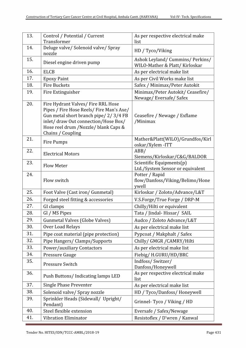
Construction of Tertiary Care Cancer Centre at Civil Hospital, Ambala Cantt. (HARYANA) Vol-IV- Tech. Specifications
Tender No. HITES/IDN/TCCC-AMBL/2018-19 Page 431
13. Control / Potential / Current Transformer
As per respective electrical make list
14. Deluge valve/ Solenoid valve/ Spray nozzle
HD / Tyco/Viking
15. Diesel engine driven pump
Ashok Leyland/ Cummins/ Perkins/ WILO-Mather & Platt/ Kirloskar
16. ELCB As per electrical make list
17. Epoxy Paint As per Civil Works make list
18. Fire Buckets Safex / Minimax/Peter Autokit
19. Fire Extinguisher Minimax/Peter Autokit/ Ceasefire/ Newage/ Eversafe/ Safex
20. Fire Hydrant Valves/ Fire RRL Hose Pipes / Fire Hose Reels/ Fire Man’s Axe/ Gun metal short branch pipe/ 2/ 3/4 FB inlet/ draw Out connection/Hose Box/ Hose reel drum /Nozzle/ blank Caps & Chains / Coupling
Ceasefire / Newage / Exflame /Minimax
21. Fire Pumps
Mather&Platt(WILO)/Grundfos/Kirloskar/Xylem -ITT
22. Electrical Motors
ABB/ Siemens/Kirloskar/C&G/BALDOR
23. Flow Meter
Scientific Equipments(p) Ltd./System Sensor or equivalent
24. Flow switch
Potter / Rapid flow/Danfoss/Viking/Belimo/Honeywell
25. Foot Valve (Cast iron/ Gunmetal) Kirloskar / Zoloto/Advance/L&T
26. Forged steel fitting & accessories V.S.Forge/True Forge / DRP-M
27. GI clamps Chilly/Hilti or equivalent
28. Gl / MS Pipes Tata / Jindal- Hissar/ SAIL
29. Gunmetal Valves (Globe Valves) Audco / Zoloto Advance/L&T
30. Over Load Relays As per electrical make list
31. Pipe coat material (pipe protection) Pypcoat / Makphalt / Safex
32. Pipe Hangers/ Clamps/Supports Chilly/ GMGR /CAMRY/Hilti
33. Power/auxiliary Contactors As per electrical make list
34. Pressure Gauge Fiebig/ H.GURU/HD/BRC
35. Pressure Switch
Indfoss/ Switzer/ Danfoss/Honeywell
36. Push Buttons/ Indicating lamps LED
As per respective electrical make list
37. Single Phase Preventer As per electrical make list
38. Solenoid valve/ Spray nozzle HD / Tyco/Danfoss/ Honeywell
39. Sprinkler Heads (Sidewall/ Upright/ Pendant)
Grinnel- Tyco / Viking / HD
40. Steel flexible extension Eversafe / Safex/Newage
41. Vibration Eliminator Resistoflex / D’wren / Kanwal
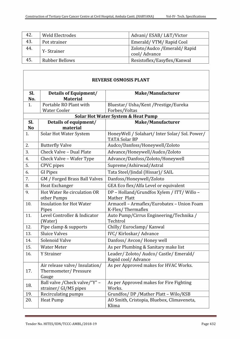
Construction of Tertiary Care Cancer Centre at Civil Hospital, Ambala Cantt. (HARYANA) Vol-IV- Tech. Specifications
Tender No. HITES/IDN/TCCC-AMBL/2018-19 Page 432
42. Weld Electrodes Advani/ ESAB/ L&T/Victor
43. Pot strainer Emerald/ VTM/ Rapid Cool
44. Y- Strainer
Zoloto/Audco /Emerald/ Rapid cool/ Advance
45. Rubber Bellows Resistoflex/Easyflex/Kanwal
REVERSE OSMOSIS PLANT
Sl. No.
Details of Equipment/ Material
Make/Manufacturer
1. Portable RO Plant with Water Cooler
Bluestar/ Usha/Kent /Prestige/Eureka Forbes/Voltas
Solar Hot Water System & Heat Pump Sl. No
Details of equipment/ material
Make/Manufacturer
1. Solar Hot Water System HoneyWell / Solahart/ Inter Solar/ Sol. Power/ TATA Solar BP
2. Butterfly Valve Audco/Danfoss/Honeywell/Zoloto
3. Check Valve – Dual Plate Advance/Honeywell/Audco/Zoloto
4. Check Valve – Wafer Type Advance/Danfoss/Zoloto/Honeywell
5. CPVC pipes Supreme/Ashirwad/Astral
6. GI Pipes Tata Steel/Jindal (Hissar)/ SAIL
7. GM / Forged Brass Ball Valves Danfoss/Honeywell/Zoloto
8. Heat Exchanger GEA Eco flex/Alfa Level or equivalent
9. Hot Water Re circulation OR other Pumps
DP – Holland/Grundfos Xylem / ITT/ Willo – Mather Platt
10. Insulation for Hot Water Pipes
Armacell – Armaflex/Eurobatex – Union Foam K-Flex/ Thermaflex
11. Level Controller & Indicator (Water)
Auto Pump/Cirrus Engineering/Technika / Techtrol
12. Pipe clamp & supports Chilly/ Euroclamp/ Kanwal
13. Sluice Valves IVC/ Kirloskar/ Advance
14. Solenoid Valve Danfoss/ Avcon/ Honey well
15. Water Meter As per Plumbing & Sanitary make list
16. Y Strainer Leader/ Zoloto/ Audco/ Castle/ Emerald/ Rapid cool/ Advance
17. Air release valve/ Insulation/ Thermometer/ Pressure Gauge
As per Approved makes for HVAC Works.
18. Ball valve /Check valve/“Y” – strainer/ GI/MS pipes
As per Approved makes for Fire Fighting Works.
19. Recirculating pumps Grundfos/ DP /Mather Platt – Wilo/KSB 20. Heat Pump AO Smith, Cristopia, Bluebox, Climaveneta,
Klima
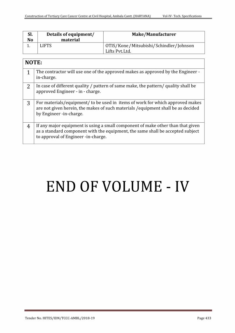
Construction of Tertiary Care Cancer Centre at Civil Hospital, Ambala Cantt. (HARYANA) Vol-IV- Tech. Specifications
Tender No. HITES/IDN/TCCC-AMBL/2018-19 Page 433
Sl. No
Details of equipment/ material
Make/Manufacturer
1. LIFTS OTIS/ Kone / Mitsubishi/ Schindler/ Johnson Lifts Pvt. Ltd.
END OF VOLUME - IV
NOTE:
1 The contractor will use one of the approved makes as approved by the Engineer -in-charge.
2 In case of different quality / pattern of same make, the pattern/ quality shall be approved Engineer - in - charge.
3 For materials/equipment/ to be used in items of work for which approved makes are not given herein, the makes of such materials /equipment shall be as decided by Engineer -in-charge.
4 If any major equipment is using a small component of make other than that given as a standard component with the equipment, the same shall be accepted subject to approval of Engineer -in-charge.