Directionally Solidified Eutectics as High Temperature ...
21
DIRECTIONALLY SOLIDIFIED EUTECTICS AS HIGH TEMPERATURE FASTENERS F. D. George United Aircraft Research Laboratories East Hartford, Connecticut Abstract In a number of laboratories, directionally solidified eutectics are being examined as candidate materials for vanes and blades in advanced gas turbines. Because of the superior high temperature properties displayed by two such alloys, a program was initiated to determine the suitability of these materials for high temperature fasteners. Material properties pertinent to fastener applications were determined as a function of temperature. These properties included shear parallel and perpendicular to the growth direction and torsion parallel to the growth direction. Several tech- niques were investigated for fabricating typical fastener shapes. These fabrication methods included grinding, creep forming and direct casting. Finally, a brief evaluation of the performance of the best fabricated fastener design was made. This study was funded by the National Aeronautics and Space Administration at Marshall Space Flight Center under contract NO. NAS8-27358. Introduction In recognition of the current and anticipated requirements for superior high temperature materials, the Materials Laboratory of UARL has directed a substantial research effort in the establishment and evaluation of a technology for growing phase-reinforced eutectic alloys. The techniques used have demonstrated that materials with su.perior mechanical properties can be processed by the directional solidification of high temperature eutectic alloys. These investigations were prompted for the main purpose of developing an alloy for use in high temperature turbine applications. Several nickel and cobalt-based, phase-reinforced composite systems have been identi- fied which display superior mechanical properties for temperatures to 2200'F. Certain of the characteristics, notably microstructural stability, tension, creep and fatigue, suggested that these type materials might qualify as high temperature fasteners for attaching thermal protection panels on space vehicles. For example, good microstruc- tura:L stability would assure non-weakening of the fastener head area at the working temperatures and high creep resistance would prevent relaxation under load and help retain a "tight joint". In comparison with other techniques for obtaining superior high temperature materials, the directionally solidified eutectic approach offers numerous advantages. One (of the most important advantages is that a eutectic composite develops its rein- forcing phase in situ by a one-step casting process. Since the composite structures -- are ,generated as a result of an equilibrium reaction, the phases produced are chemically stable with respect to one another. Furthermore, experience has shown that the low energy interfaces, established during the growth, result in a micro- structure with exceptional stability which resists coarsening and spheroidization. Mechanically, as a first approximation, the behavior of these materials can be treated as normal composites. Recently it has been shown, however, that there is an important U-l
Transcript of Directionally Solidified Eutectics as High Temperature ...
DIRECTIONALLY SOLIDIFIED EUTECTICS AS HIGH TEMPERATURE FASTENERS
F. D. George United Aircraft Research Laboratories
East Hartford, Connecticut
Abstract
In a number of laboratories, directionally solidified eutectics are being examined as candidate materials for vanes and blades in advanced gas turbines. Because of the superior high temperature properties displayed by two such alloys, a program was initiated to determine the suitability of these materials for high temperature fasteners.
Material properties pertinent to fastener applications were determined as a function of temperature. These properties included shear parallel and perpendicular to the growth direction and torsion parallel to the growth direction. Several tech- niques were investigated for fabricating typical fastener shapes. These fabrication methods included grinding, creep forming and direct casting. Finally, a brief evaluation of the performance of the best fabricated fastener design was made.
This study was funded by the National Aeronautics and Space Administration at Marshall Space Flight Center under contract NO. NAS8-27358.
Introduction
In recognition of the current and anticipated requirements for superior high temperature materials, the Materials Laboratory of UARL has directed a substantial research effort in the establishment and evaluation of a technology for growing phase-reinforced eutectic alloys. The techniques used have demonstrated that materials with su.perior mechanical properties can be processed by the directional solidification of high temperature eutectic alloys. These investigations were prompted for the main purpose of developing an alloy for use in high temperature turbine applications. Several nickel and cobalt-based, phase-reinforced composite systems have been identi- fied which display superior mechanical properties for temperatures to 2200'F. Certain of the characteristics, notably microstructural stability, tension, creep and fatigue, suggested that these type materials might qualify as high temperature fasteners for attaching thermal protection panels on space vehicles. For example, good microstruc- tura:L stability would assure non-weakening of the fastener head area at the working temperatures and high creep resistance would prevent relaxation under load and help retain a "tight joint".
In comparison with other techniques for obtaining superior high temperature materials, the directionally solidified eutectic approach offers numerous advantages. One (of the most important advantages is that a eutectic composite develops its rein- forcing phase in situ by a one-step casting process. Since the composite structures -- are ,generated as a result of an equilibrium reaction, the phases produced are chemically stable with respect to one another. Furthermore, experience has shown that the low energy interfaces, established during the growth, result in a micro- structure with exceptional stability which resists coarsening and spheroidization. Mechanically, as a first approximation, the behavior of these materials can be treated as normal composites. Recently it has been shown, however, that there is an important
U-l
effect of interphase spacing on strength. Reducing this spacing, which is accomplished by growing the material at a faster rate, has strengthened the material according to a Hall-Petch relationship. Thus, not only is processing benefited by rate increases but also properties.
Included in the disadvantages in the eutectic approach are anisotropic properties (as with other composites), a general inability to vary randomly the volume fraction of the phases, and some lack of freedom in selection of interesting systems. These last two disadvantages occur because we have selected to use a eutectic or eutectic- like composition where two or more phases crystallize simultaneously from a liquid. Even within these limitations, there are countless systems which can be anticipated if one considers ternary and higher order systems for study and development.
The prime material evaluated in this study was the directionally solidified Ni3Al-Ni3Cb eutectic alloy (l-5). After solidification the microstructure consists of a lamellar (sheet-like) dispersion of Ni3Cb within a Ni3Al matrix (Fig. 1). It. contains approximately 44 volume percent of the Ni3Cb reinforcing phase and the Ni3Al matrix (a ductile intermetallic compound) is strengthened substantially by the 8 at. % columbium dissolved within it. The eutectic melting temperature is 2335'F and its density is 8.5 gm/cc. The alloy is a high modulus material whose tensile strength and creep-rupture strength are markedly superior to conventional superalloys. It is mildly notch sensitive at room temperature but is notch insensitive at elevated tem- peratures. Although it possesses low tensile ductility at room temperature, this does not mean the material is brittle. Its toughness is, in fact, comparable to superalloys at room temperature. The fatigue strength of the alloy is outstanding at room temperature , greatly surpassing that of nickel superalloys. This eutectic alloy exhibits such remarkable properties by virtue of the directional nature of its micro- structure. The properties of the material are, as a consequence, directional. This material offers interesting possibilities for application as a high temperature fastener and if successfully developed, should satisfy performance requirements which cannot be met by conventional materials.
Since the Ni3Al-Ni3Cb alloy is representative of only one class of eutectic com- posites, i.e. the lamellar reinforced, a limited evaluation of the (Co,Cr)-(Cr,Co)TC3 eutectic (6-9) which is representative of the fibrous reinforced eutectic composite was also included in this program. This cobalt-based eutectic was modified by the addition of aluminum for the purpose of improving its oxidation resistance and to aid in stabilizing the cubic form of the cobalt in the alloy. The microstructure of this alloy is fibrous in nature (Fig, 1) and consists of approximately 26 volume percent of the carbide reinforcing phase with a cobalt, chromium, aluminum solid solution matrix. It has a density of 8.0 m/cc and a melting temperature of 2370'F. Although not as strong as the Ni3Al-Ni3Cb eutectic alloy, easily grown -
the (Co,Cr,Al)-(Cr,Co)+!3 eutectic is more rates of 50 cm/hr are typical - and is more oxidation resistant than
the Ni3ALNi3Cb eutectic. This alloy is stronger than the conventional cast nickel- base superalloys in tension and creep and has cornparabLe impact toughness. Because of the presence of the aligned fibrous carbide phase, it displays a high elastic modulus at room and elevated temperatures.
Other exsmples of "exotic" alloys which have been selected for study as candi- date materials for potential use as high temperature structural fasteners include a dispersion strengthened metal TD NiCr (10) and these evaluations will be used for comparison purposes where possible.
u-2
Melting and Solidification Process
Master melts of eutectic composition were made in alumina crucibles and chill- cast in copper molds. The resulting bars were then placed in l/2 inch diameter 99.7% recrystallized alumina cylindrical crucibles and unidirectionally solidified verti- cally within a resistively heated graphite tube furnace under a dynamic argon atmosphere (Fig. 2). These crucibles were held in a graphite sleeve which separated the crucible bottom from a water cooled brass pedestal by l/4 inch of graphite. The crucibles were lowered from the furnace at rates corresponding to a nominal* solidi- fication velocity of 2 cm/hr for the Ni3Al-Ni3Cb eutectic and 10 cm/hr for the (Co,C!r,Al)-(Cr,Co)7C3 eutectic. Liquid superheats of approximately 500'F were employed and the thermal gradient in the liquid was estimated to have been 16C°F/cm. Several l/2 inch diameter ingots of both materials were formed as cast products by this vertical Bridgman-type directional solidification process. These ingots were then ground into test samples for the determination of the material properties pertinent to fastener application.
Material Property Evaluation Pertinent to Fastener Application
Transverse Shear --
Bar samples rectangular in cross-section, l/8 inch x l/4 inch x 1 inch, were ground from the l/2 inch diameter ingots with the direction of solidification parallel to the ILongest dimension so the strength in shear perpendicular (transverse) to the growth direction might be measured.
A double shear test fixture was used in this evaluation and initially the effect of span variations and the effect of the sample ends being clamped or free on the room temperature transverse shear strength were determined. High shear strength values were measured at short spans (0.010 inch) where the sample was supported in part by the anvil and lower apparent shear strengths were measured at longer spans (0.073 inch where failure appeared to have occurred partly by bending. Samples tested at the intermediate span distances appeared to have failed in shear and the mean value was considered as the effective shear strength of the material at room temperature. There was little effect due to clamping the sample ends at the intermediate spans where shear failures were observed. Because of this all high temperature tests were run with free ends at a constant span (0.030 inch) within the intermediate range. 'The transve:rse shear tests were performed at a loading rate of 0.01 in./min.
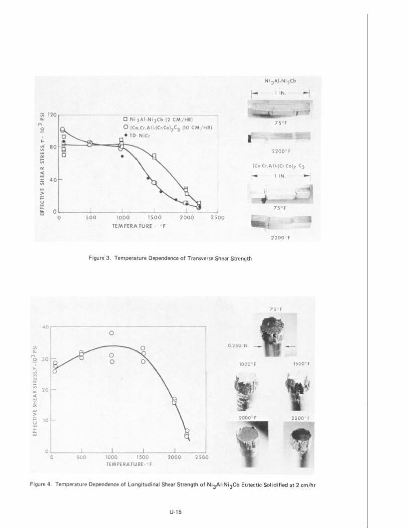
In Fig. 3, a plot of effective shear stress vs. temperature indicates that the transverse shear strength of the Ni3Al-Ni3Cb eutectic is insensitive to temperature up to IOOO'F. The transversely oriented Ni3Al-Ni3Cb displayed increasing ductility with temperature. The specimens pictured indicate the brittle failure at room tem- perature and the ductile behavior at 2200'F. The temperature dependence of transverse shear strength of the (Co,Cr,Al)-(Cr,Co)TC3 material is also shown in Fig. 3. This eutectic shows only a slight decrease in shear strength up to 1OOO'F and at that temperature exhibits a shear strength equivalent to that observed for the Ni3Al-Ni3Cb eutectic. Above this temperature, the shear strength drops off rather rapidly. The test specimens in Fig. 3 also show the increase in ductility with temperature. Finally,
--- *The failure to develop an exactly uniform rate of growth is primarily the result of
the changing thermal gradient in the solid.
in Fig. 3, the shear strength values determined for l/4 inch diameter specimens of TD NiCr (10) based on double shear testing are also shown. This dispersion strength- ened metal which had been selected for study as a candidate material for potential use as a high temperature fastener yielded values that closely compare with those obtained for the fibrous (Co,Cr,Al)-(Cr,Co)7C3 eutectic.
Longitudinal Shear
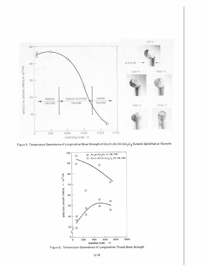
Test specimens of both eutectic alloys for measuring longitudinal shear strength, shear parallel to the direction of solidification, were ground to shape and tested, These specimens consisted of a l/4 inch diameter bolt shank with two l/8 inch thick heads (one at each end of the shank) which were attached to a fixture composed of two high temperature slotted button-head adapters and split ring washers (to assure full bearing on the specimen heads). All longitudinal shear tests were run at a loading rate of 0.01 in./min and a shearing span distance of 0.010 inch.
The longitudinal shear strength values were determined using the diameter of the bolt shank in calculating the shear area. This approximation was used in the NijAl- Ni3Cb eutectic tests because the actual sheared area, as seen in Fig. 4, was not perfectly cylindrical which reflects the effect of the different orientations of the lamellae in the various grains sheared. A large amount of plasticity at the two higher temperatures is evident from the photographs in Fig. 4 of the specimens tested at these temperatures. The temperature dependence of longitudinal shear strength of the NisAl-Ni3Cb alloy is also shown in Fig. 4. An initial increase in longitudinal shear strength with an increase in temperature is evident. This increase is undoubted partly due to the increase in the flow stress of the NixAl phase with temperature. This anomalous behavior has also been found in a Ni3(A1,Cb) single phase alloy, which is similar to the matrix phase of this eutectic, by Thornton, et al (11). The yield strength of this intermetallic compound increases with temperature up to approximately 1292OF.
lY
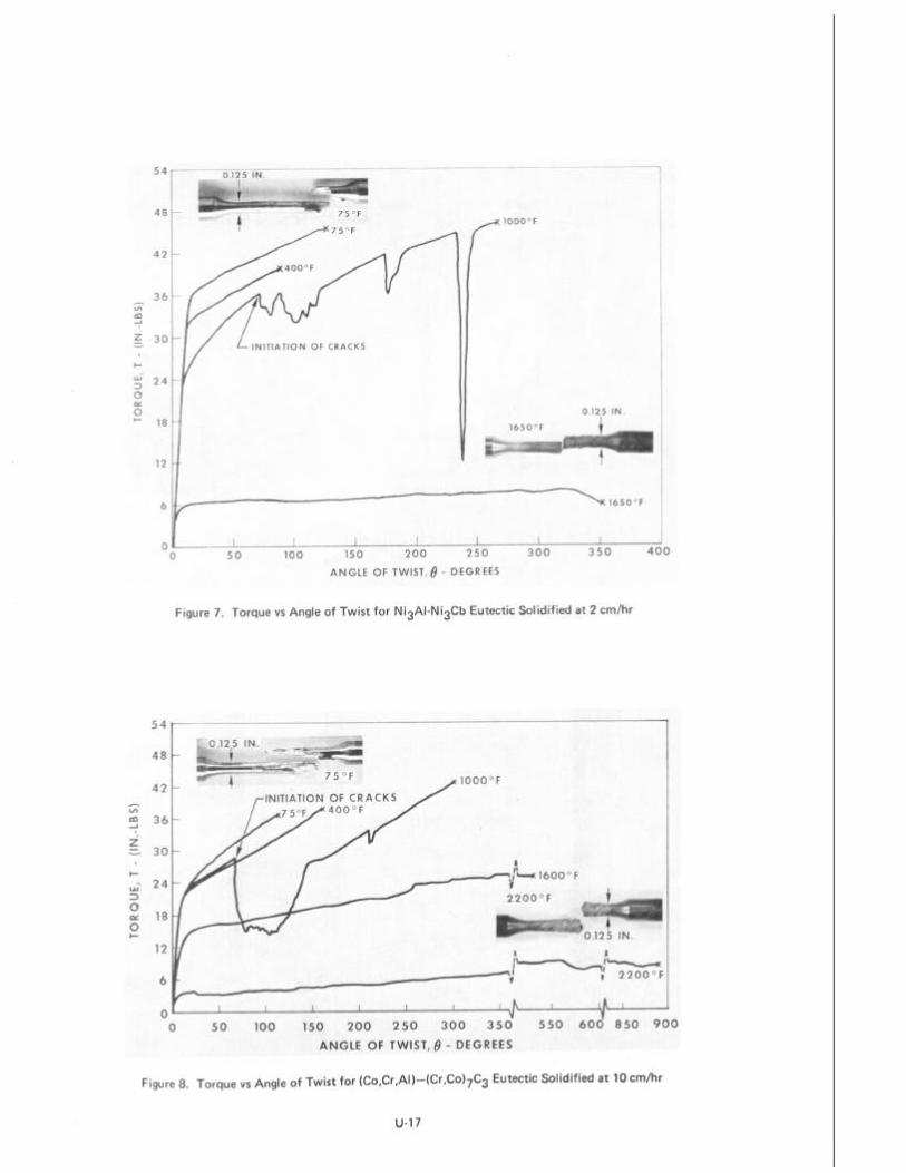
The temperature dependence of longitudinal shear strength of the (Co,Cr,Al)- (Cr,Co)7C3 alloy is shown in Fig. 5. The photographs of fractured specimens at the various temperatures clearly indicate a transition from a tensile mode of failure to a shear mode of failure with increasing temperature. Although the failure mode of most of these specimens did not appear to be purely shear, the effective shear strength values were determined by using the bolt shank diameter in calculating the shear area.
Longitudinal Thread Shear
Longitudinal thread shear specimens 2 inches long with l/4-20 threads at either end were ground from both eutectic ingots with the direction of solidification parallel to the long dimension. All longitudinal thread shear tests were run at a loading rate of 0.01 in./min. Because of the difficulty in determining the shear area in these test samples, several shadowgraphs were taken from different sides of the shear frac- ture surface and different areas were obtained. The shear strength values varied depending on the area used in the calculation and therefore an average value was used. In some more difficult cases, the values were calculated from shear areas determined from actual measurements (the width and length of thread sheared and the remaining sheared diameter).
The temperature dependence of longitudinal thread shear strength of the NixAl- NixCb eutectic is shown in Fig. 6. Although the thread shear strength values obtained are higher than the values reported for the longitudinal shear strengths, the behavior
of both appears similar with higher apparent thread shear determining the sheared area
Although an increase in ture was previously e-vident shear strength (Fig. 6). As
respect to the materials response to temperature. The strength values may be due to the difficulty in accurately
longitudinal shear strength with an increase in tempera- Fig. 4), it is more dramatic in the longitudinal thread previously mentioned, this is partly due to the increase
in the flow stress of the Ni3Al phase with temperature. This longitudinal shear strength increase in the thread tests may also be due in part to the increasing shear ductility which would allow more uniform engagement of the specimen threads and test adapt,er,,
The temperature dependence of longitudinal thread shear strength of the (Co,Cr,Al)- (Cr,C!o)$3 eutectic is also shown in Fig. 6. The thread shear strength values obtained are higher than the values reported for the longitudinal shear strengths, but again the behavior of both appears similar with respect to the materials response to tem- perature. The higher apparent thread shear strength values may again be due to the difficulty in accurately determining the sheared area.
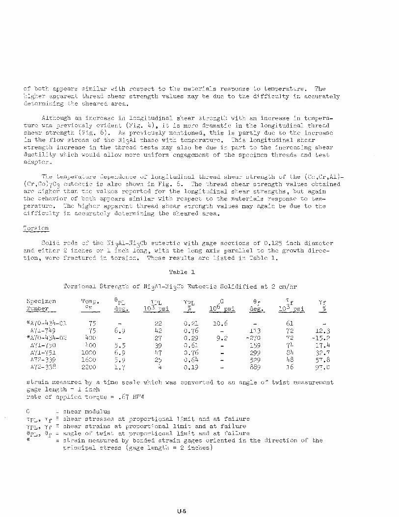
Torsion
Solid rods of the Ni3Al-Ni3Cb eutectic with gage sections of 0.125 inch diameter and either 2 inches or 1 inch long, with the long axis parallel to the growth direc- tion, were fractured in torsion. These results are listed in Table 1.
Table 1
Torsional Strength of Ni3Al-Ni3Cb Eutectic Solidified at 2 cm/hr
Specimen Temp. ePL IPL 103 psi
YPL Tf Number OF
Of --- deg. % 10GGpsi w lo3 psi
*A70-434-01 75 6-9 E
0.21 10.6 - 61 A71-749
4:: : 0.76 - 113 72
*ATO-434-02 27 0.29 9.2 -270 72 A71-750 400 2:; zy 0.61 - 159 74 A7l-751 1000 0.76 - 299 84 A72-339 1600 5.9 25 0.64 - 529 48 ~72-338 2200 1.7 4 0.19 - 889 16
Yf z
12.3 15.2 17.4 32.7 57.8 97.0
strain measured by a time scale which was converted to an angle of twist measurement gage length = 1 inch rate of applied torque = .67 RPM
G f shear modulus TPL> Tf 5 shear stresses at proportional limit and at failure ypL, yf z shear strai.ns at proportional limit and at failure OPL, Of z angle of twist at proportional limit and at failure * G strain measured by bonded strain gages oriented in the direction of the
principal stress (gage length = 2 inches)
u-5
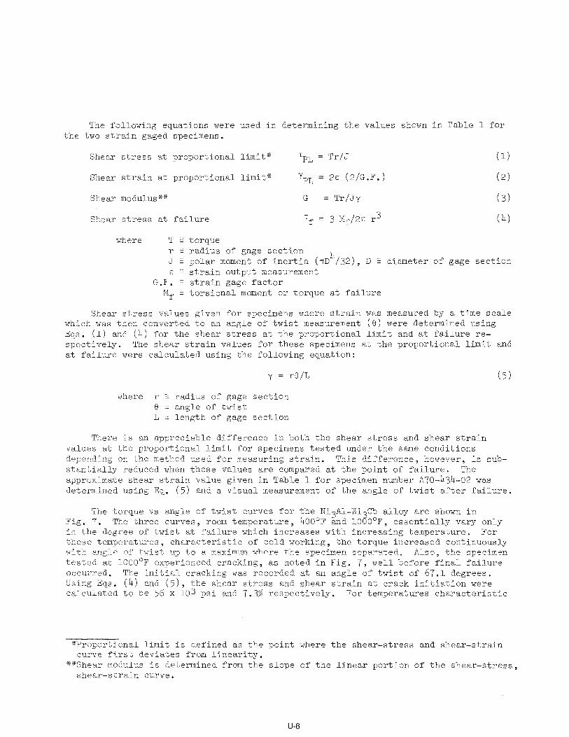
the The following equations were used in determining the values shown in Table 1 for
two strain gaged specimens.
Shear stress at proportional limit* T pL = Tr/J (1)
Shear strain at proportional limit* Y pL = 2~ (2/G.F.) (2)
Shear modulus** G = Tr/Jy (3)
Shear stress at failure Tf = 3 Mf/27r r3 (4)
where T E torque r - radius of gage section J E polar moment of inertia (~rD~/32), D 3 diameter of gage section s 3 strain output measurement
G.F. q strain gage factor M, q torsional moment or torque at failure
Shear stress values given for specimens where strain was measured by a time scale which was then converted to an angle of twist measurement (8) were determined using Eqs. (1) and (4) for the shear stress at the proportional limit and at failure re- spectively. The shear strain values for these specimens at the proportional limit and at failure were calculated using the following equation:
y = rB/L (5)
where r Z radius of gage section 8 2 angle of twist L Z length of gage section
There is an appreciable difference in both the shear stress and shear strain values at the proportional limit for specimens tested under the same conditions depending on the method used for measuring strain, This difference, however, is sub- stantially reduced when these values are compared at the point of failure. The approximate shear strain value given in Table 1 for specimen number ATO-434-02 was determined using Eq. (5) and a visual measurement of the angle of twist after failure.
The torque vs angle of twist curves for the NixAl-Ni Cb alloy are shown in Fig. 7. The three curves, room temperature, 400'F and 10 a O°F, essentially vary only in the degree of twist at failure which increases with increasing temperature. For these temperatures, characteristic of cold working, the torque increased continuously with angle of twist up to a maximum where the specimen separated. Also, the specimen tested at 1OOO'F experienced cracking, as noted in Fig. 7, well before final failure occurred. The initial cracking was recorded at an angle of twist of 67.1 degrees. Using Eqs. (4) and (5), the shear stress and shear strain at crack initiation were calculated to be 56 x 103 psi and 7.3% respectively. For temperatures characteristic
*Proportional limit is defined as the point where the shear-stress and shear-strain curve first deviates from linearity.
**Shear modulus is determined from the slope of the linear portion of the shear-stress, shear-strain curve.
U-6
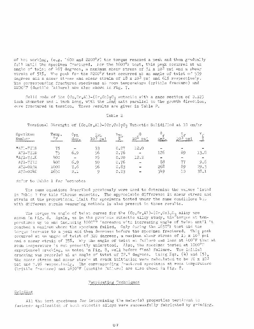
of hot working, (e.g. 1600 and 2200'F) the torque reached a peak and then gradually fell until the specimen fractured. For the 1600'F test, this peak occurred at an angle of twist of 467 degrees, a maximum shear stress of 51 x 103 psi and a shear strain of 51%. The peak for the 2200'F test occurred at an angle of twist of 559 degrees and a shear stress and shear strain of 18 x 103 psi and 61% respectively. The corresponding fractured specimens at room temperature (brittle fracture) and 2200°F (ductile failure) are also shown in Fig. 7.
Solid rods of the (Co,Cr,Al)-(Cr,Co)7C3 eutectic with a gage section of 0.125 inch diameter and 1 inch long, with the long axis parallel to the growth direction, were fractured in torsion. These results are given in Table 2.
Table 2
Torsional Strength of (Co,Cr,Al)-(Cr,Co)7C3 Eutectic Solidified at 10 cm/hr
Specimen Number ---
Temp. @PL TPL yPL G e OF 103 psi % 106 psi
?f yf deg. cJe& lo3 psi 2
*A71-771D A7&771U
*A71-771E A71-771X ~72-012'ii ~72-004~
75
43: 400 1000 1650
6:9
6T9 7.6 2.1
:z
25 ::
9
0.27 12.0 0.76 - 126 i?9 13.8
0.20 12.2 - 0.76 - ia Y-7 9.6 0.83 - 268 89 29.3 0.23 - 349 10 38.1
Refer to Table 1 for footnotes
The same equations described previously were used to determine the values listed in Table 2 for this fibrous eutectic. The appreciable difference in shear stress and strain at the proportional limit for specimens tested under the same conditions but with different strain measuring methods is also present in these results.
The torque vs angle of twist curves for the (Co,Cr,Al)-(Cr,Co)7C3 alloy are shown in Fig. 8. Again, as in the previous eutectic alloy study, the torque at tem- peratures up to and including 1OOO'F increased with increasing angle of twist until it reached a maximum where the specimen failed. Only during the 1650'F test did the torque increase to a peak and then decrease before the specimen fractured. This peak occurred at an angle of twist of 320 degrees, a maximum shear stress of 15 x lo3 psi and a. shear strain of 35%. Why the angle of twist at failure was less at 400'F than at room temperature is not presently understood. Also, the specimen tested at 1000°F experienced cracking, as noted in Fig. 8, well before final failure. The initial cracking was recorded at an angle of twist of 72.7 degrees. Using Eqs. (4) and (5), the shear stress and shear strain at crack initiation were calculated to be 70 x lo3 psi and 7.9% respectively. The corresponding fractured specimens at room temperature (brittle fracture) and 1650~~ (ductile failure) are also shown in Fig. 8.
Fabricating Techniques
Grinding -cc-
All the test specimens for determining the material properties pertinent to fastener application of both eutectic alloys were successfully fabricated by grinding.
u-7
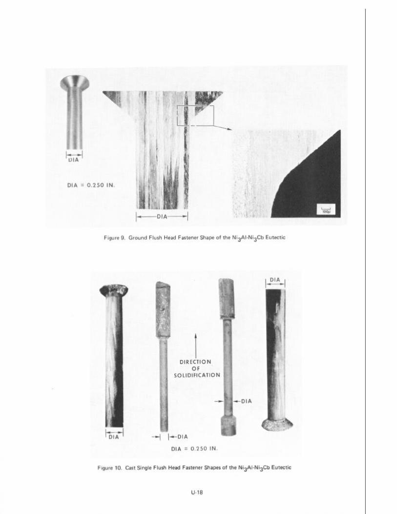
A typical flush head fastener shape of the Ni3Al-Ni3Cb eutectic that was fabri- cated by grinding is shown in Fig. 9. The direction of solidification is parallel to the long axis of the fastener. Various lamellar orientations, all parallel to the growth direction, are evident from the two microstructural views in Fig. 9. Several double flush headed specimens were ground to shape from Ni3Al-Ni3Cb ingots directionally solidified at 2 cm/hr for use in evaluating this process as a method for fabricating fasteners.
Casting
Two mold designs were used for the purpose of determining the feasibility of directly casting the Ni3Al-Ni Cb eutectic into a typical flush head fastener shape. One design allowed directiona ? solidification to proceed from the fastener shank to the flush head and the other allowed directional solidification from the flush head shape into the shank. Figure 10 shows two eutectic ingots that were successfully solidified at 2 cm/hr using both of these designs. The center photographs in Fig. 10 show the ingots after removal from the high purity alumina mold in which they were directionally cast. There appears to be no indication of a metal-mold reaction. The outermost photographs show the cast fastener shapes after macro-etching their sur- faces. It is evident from the grain alignment seen in these photographs that the solidification was directional.
shape A double flush headed specimen of the Ni3Al-Ni3Cb eutectic that was cast into
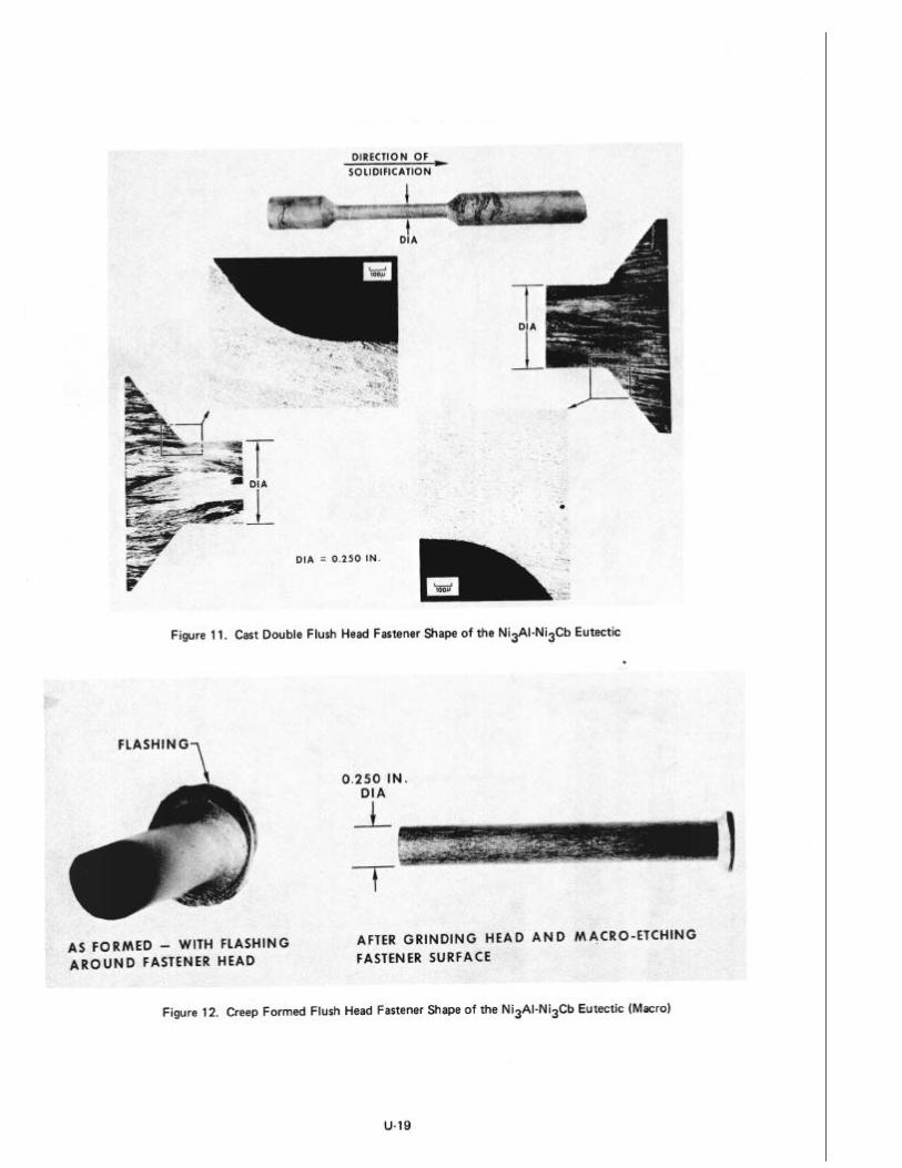
at 2 cm/hr is shown in Fig. 11. The top photograph shows the ingot after removal from the high purity alumina mold in which it was directionally cast. Again, there appears to be no indication of a metal-mold reaction. Microstructural examina- tion of the views shown in Fig. 11 indicates a relatively gradual transition of the eutectic grain alignment through the two flush headed shapes of the cast ingot.
A few single and double 100' flush headed specimens of the Ni3Al-Ni3Cb eutectic were directionally cast in order to evaluate this process as a method of fabricating fasteners.
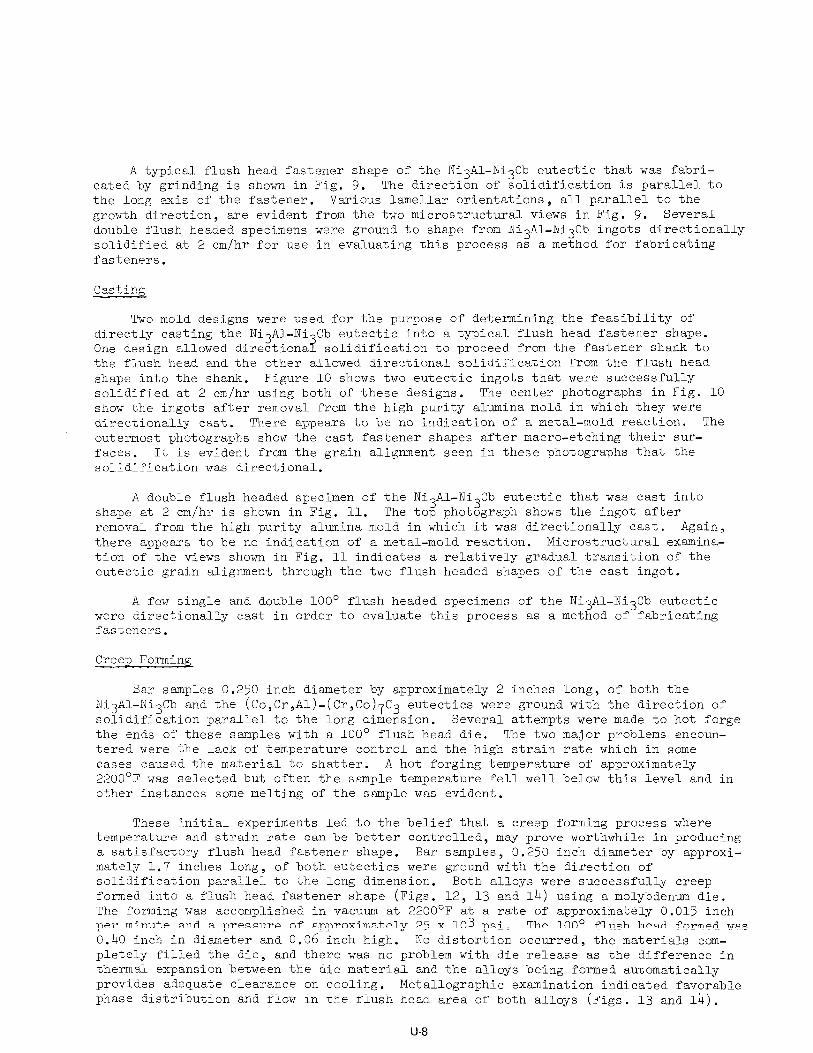
Creep Forming
Bar samples 0.250 inch diameter by approximately 2 inches long, of both the Ni3Al-Ni3Cb and the (Co,Cr,Al)-(Cr,Co)7C3 eutectics were ground with the direction of solidification parallel to the long dimension. Several attempts were made to hot forge the ends of these samples with a 100' flush head die. The two major problems encoun- tered were the lack of temperature control and the high strain rate which in some cases caused the material to shatter. A hot forging temperature of approximately 2200°F was selected but often the sample temperature fell well below this level and in other instances some melting of the sample was evident.
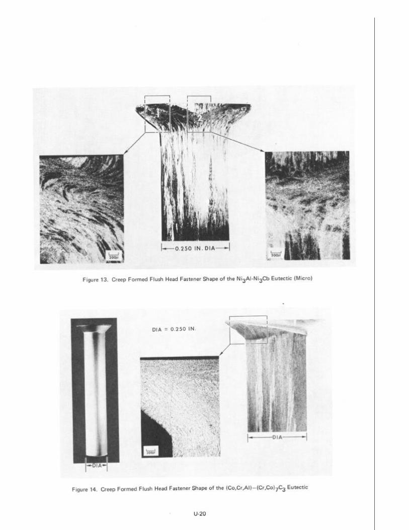
These initial experiments led to the belief that a creep forming process where temperature and strain rate can be better controlled, may prove worthwhile in producing a satisfactory flush head fastener shape. Bar samples, 0.250 inch diameter by approxi- mately 1.7 inches long, of both eutectics were ground with the direction of solidification parallel to the long dimension. Both alloys were successfully creep formed into a flush head fastener shape (Figs. 12, 13 and 14) using a molybdenum die. The forming was accomplished in vacuum at 2200°F at a rate of approximately 0.015 inch per minute and a pressure of approximately 25 x 103 psi. The 100' flush head formed was 0.40 inch in diameter and 0.06 inch high. No distortion occurred, the materials com- pletely filled the die, and there was no problem with die release as the difference in thermal expansion between the die material and the alloys being formed automatically provides adequate clearance on cooling. Metallographic examination indicated favorable phase distribution and flow in the flush head area of both alloys (Figs. 13 and 14).
U-8
Several specimens were fabricated to determine the shear strength of these eutectic materials when made into a typical fastener shape using the creep forming process,
Evaluation of Fabricated Fasteners
The material properties pertinent to fastener applications which have been deter- mined for both the lamellar Ni Al-Ni3Cb and the fibrous (Co,Cr,Al)-(Cr,Co)$Z3 directionally solidified eutec 6 1c alloys are encouraging and indicate that these alloys show promise as candidate materials for high temperature fastener applications.
A 100' countersunk flush head design was chosen as a typical fastener shape for the evaluation of fabricated fasteners because this configuration is common in the assembly of skin panels to substructures where a flush surface is required.
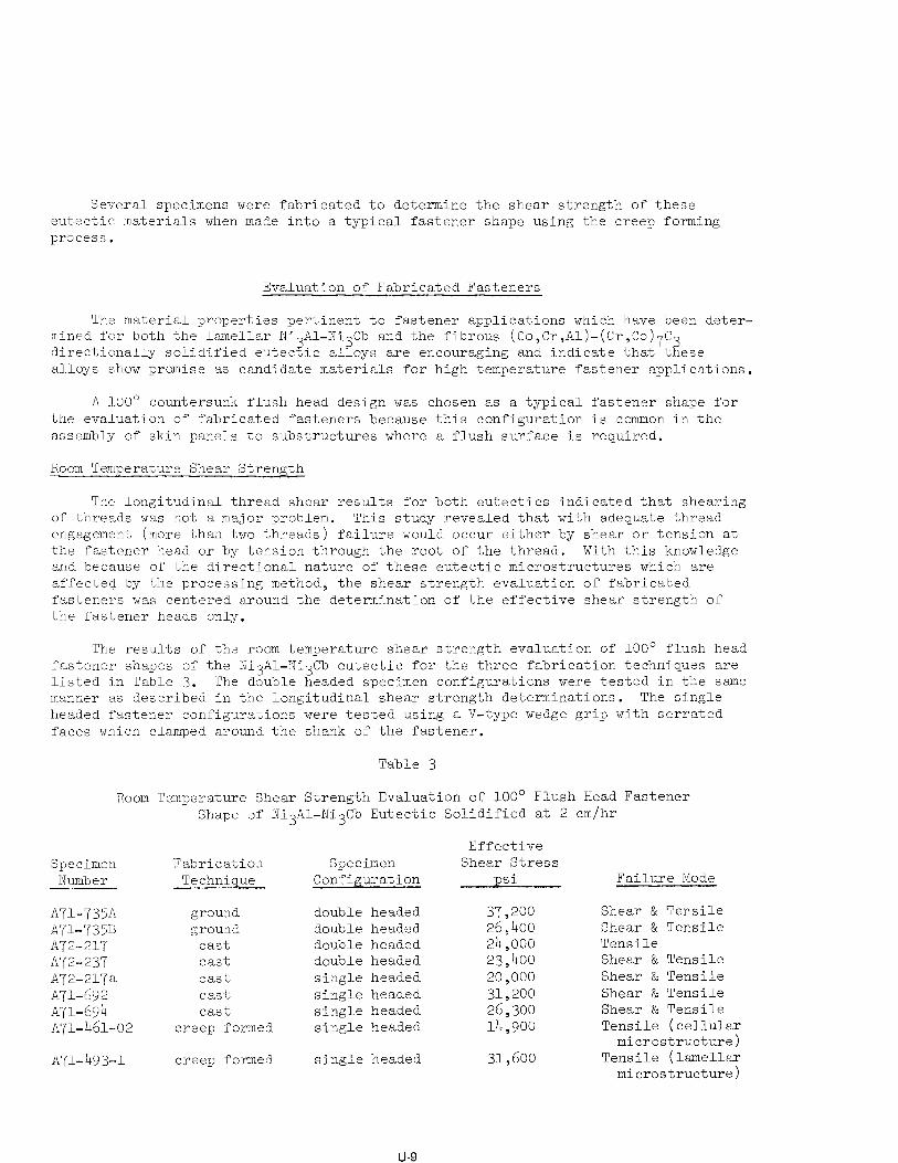
Room Temperature Shear Strength
The longitudinal thread shear results for both eutectics indicated that shearing of threads was not a major problem. This study revealed that with adequate thread engagement (more than two threads) failure would occur either by shear or tension at the fastener head or by tension through the root of the thread. With this knowledge and bsecause of the directional nature of these eutectic microstructures which are affected by the processing method, the shear strength evaluation of fabricated fasteners was centered around the determination of the effective shear strength of the fastener heads only.
The results of the room temperature shear strength evaluation of 100' flush head fastener shapes of the NixAl-Ni3Cb eutectic for the three fabrication techniques are listed in Table 3. The double headed specimen configurations were tested in the same manner as described in the longitudinal shear strength determinations. The single headed fastener configurations were tested using a V-type wedge grip with serrated faces which clamped around the shank of the fastener.
Table 3
Room Temperature Shear Strength Evaluation of 100' Flush Head Fastener Shape of Ni3Al-Ni3Cb Eutectic Solidified at 2 cm/hr
Specimen Number ~--
Fabrication Technique
Effective Specimen Shear Stress
Configuration psi Failure Mode
AU-735A ground double headed 37,200 A71-735B ground double headed 26,400 A72-217 cast double headed 24,000 A72-237 cast double headed 23,400 A72-217a cast single headed 20,000 A71-692 cast single headed 31,200 A71-6~94 cast single headed 26,300 A71-461-02 creep formed single headed 14,900
A71-4-93-l creep formed single headed 31,600
Shear & Tensile Shear & Tensile Tensile Shear & Tensile Shear & Tensile Shear & Tensile Shear & Tensile Tensile (cellular
microstructure) Tensile (lamellar
microstructure)
u-9
Most of the effective shear stress values listed in Table 3 compare favorably with those plotted in Fig. 4 with the following exceptions, the higher value of 37,200 psi for the double headed ground specimen and the lower value of 14,900 psi for the creep formed specimen. This low value can be explained by the fact that microstructural examination after testing revealed that the specimen contained a cellular microstructure near the fastener head. This local breakdown in the lamellar microstructure could cause a weakening of the material in that area when exposed to 2200°F during the forming process.
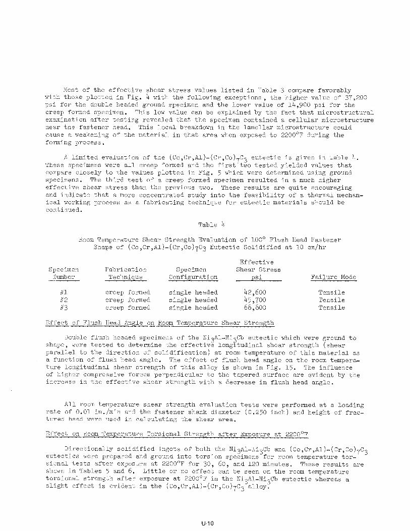
These A limited evaluation of the (Co,Cr,A1)-(Cr,Co)7C3 eutectic is given in Table 4.
specimens were all creep formed and the first two tested yielded values that compare closely to the values plotted in Fig. 5 which were determined using ground specimens. The third test of a creep formed specimen resulted in a much higher effective shear stress than the previous two. These results are quite encouraging and indicate that a more concentrated study into the feasibility of a thermal mechan- ical working process as a fabricating technique for eutectic materials should be continued.
Table 4
Room Temperature Shear Strength Evaluation of 100' Flush Head Fastener Shape of (Co,Cr,Al)-(Cr,Co)7C3 Eutectic Solidified at 10 cm/hr
Specimen Fabrication Number Technique
Effective Specimen Shear Stress
Configuration psi Failure Mode
#l #2 #3
creep formed single headed 42,600 Tensile creep formed single headed 45,700 Tensile creep formed single headed 68,800 Tensile
Effect of Flush Head Angle on Room Temperature Shear Strength
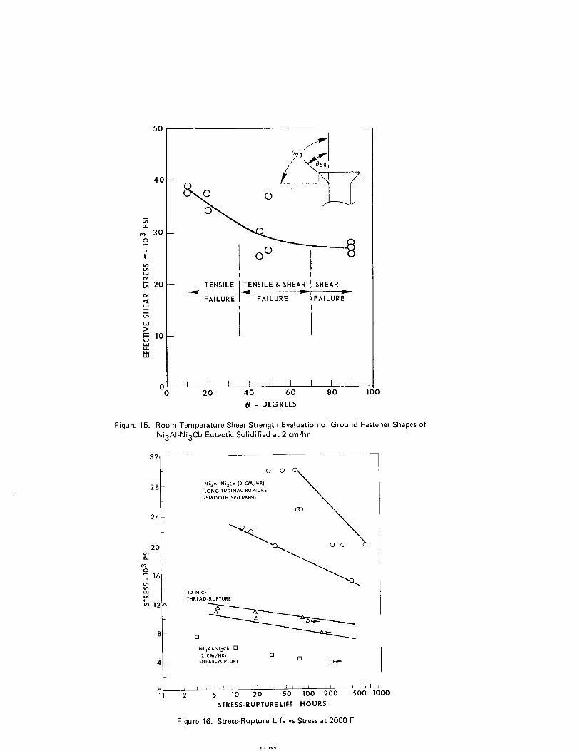
Double flush headed specimens of the Ni3Al-Ni3Cb eutectic which were ground to shape, were tested to determine the effective longitudinal shear strength (shear parallel to the direction of solidification) at room temperature of this material as a function of flush head angle. The effect of flush head angle on the room tempera- ture longitudinal shear strength of this alloy is shown in Fig. 15. The influence of higher compressive forces perpendicular to the tapered surface are evident by the increase in the effective shear strength with a decrease in flush head angle.
All room temperature shear strength evaluation tests were performed at a loading rate of 0.01 in./min and the fastener shank diameter (0.250 inch) and height of frac- tured head were used in calculating the shear area.
Effect on Room Temperature Torsional Strength after Exposure at 2200°F
Directionally solidified ingots of both the Ni3Al-Ni3Cb and (CO,C~,A~)-(C~,C~)~C~ eutectics were prepared and ground into torsion specimens for room temperature tor- sional tests after exposure at 2200'F for 30, 60, and 120 minutes. These results are shown in Tables 5 and 6. Little or no effect can be seen on the room temperature torsional strength after exposure at 2200'F in the Ni3Al-Ni3Cb eutectic whereas a slight effect is evident in the (Co,Cr,Al)-(Cr,Co)7C3 alloy.
U-IO
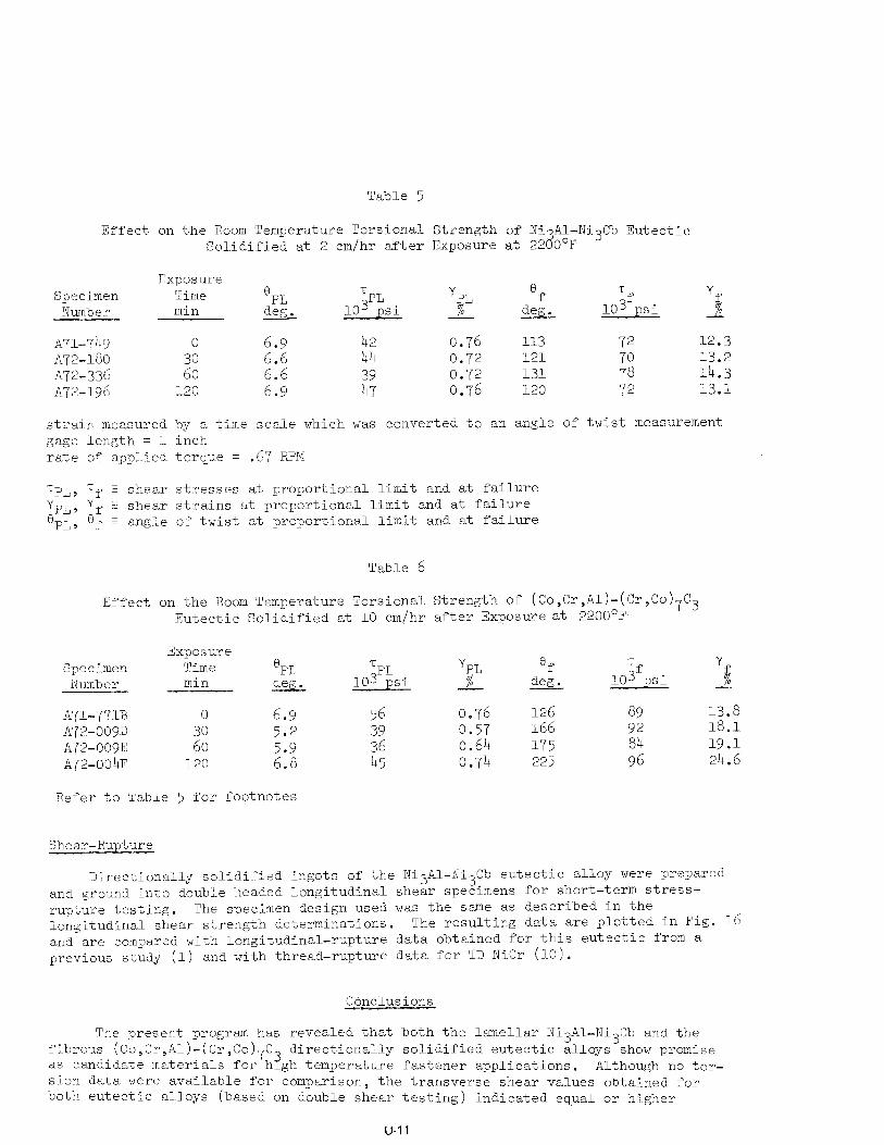
Table 5
Effect on the Room Temperature Torsional Strength of Xi Al-Ni3Cb Eutectic Solidified at 2 cm/hr after Exposure at 22 O°F a
Exposure Specimen Time 0
Number min --- d&
A71-'749 0 6.9 ~72-:180 6.6
A72-:336
2:
~72-:196 120 2::
strain measured by a time scale wh gage Ilength = 1 inch rate of applied torque = .67 RPM
TPL lo3 psi
yPL 6
f Tf lo3 psi
Yf A- - deg. %
42 0.76 113 44 0.72 121
z”i 0.72 0.76 131 120
ich was converted to an angle of tw
72 12.3
;i 13.2 14.3 72 13.1
ist measurement
TPL, Tf : shear stresses at proportional limit and at failure yP1,) "ff 5 shear strains at proportional limit and at failure ePLy '@f = angle of twist at proportional limit and at failure
Table 6
Effect on the Room Temperature Torsional Strength of (Co,Cr,Al)-(Cr,Co)7C3 Eutectic Solidified at 10 cm/hr after Exposure at 2200'F
Exposure Specimen Time ePL TPL yPL Of Tf Y
Number min deg. 103 psi A. - deg. lo3 psi % 0 --
A71-771B 0 6.9 56 0.76 126 89 13.8 A'j'2-009D 2: 5.2 39 0.57 166 92 18.1 A72,-009E 36 0.64 175 84 19.1 A72-004F 120
2:: 45 0.74 225 96 24.6
Refer to Table 5 for footnotes
Shear-Rupture
Directionally solidified ingots of the NixAl-Ni3Cb eutectic alloy were prepared and ground into double headed longitudinal shear specimens for short-term stress- rupture testing. The specimen design used was the same as described in the longitudinal shear strength determinations. The resulting data are plotted in Fig. and are compared with longitudinal-rupture data obtained for this eutectic from a previous study (1) and with thread-rupture data for TD NiCr (10).
Conclusions
16
The present program has revealed that both the lamellar Ni3Ai-Ni3Cb and the fibrous (Co,Cr,Al)-(Cr,Co)7C3 directionally solidified eutectic alloys show promise as candidate materials for high temperature fastener applications. Although no tor- sion data were available for comparison, the transverse shear values obtained for both eutectic alloys (based on double shear testing) indicated equal or higher
U-l 1
strengths than that reported for dispersion strengthened metals (e.g. TD NiCr) which were selected in a previous study for potential use as structural fasteners. The stress-rupture characteristics of the Ni3Al-Ni3Cb eutectic compare favorably with that of TD NiCr considering the difference in the testing mode used in obtaining the data, Finally, this study has indicated that a eutectic material can be successfully formed to shape by grinding, casting, (creep forming).
and thermal-mechanical working
Acknowledgements
The author gratefully acknowledges Dr. E. R. Thompson and Dr. C. 0. Hulse for their technical contributions to the accomplishment of the program goals, Mr. J. Hermann for his metallographic work, and Miss J. Hurlburt and Mrs. D. Gelinas for preparing the manuscript.
References
1.
2.
3.
4.
5.
6.
7.
8.
9.
10.
11.
Thompson, E. R. and F. D. George: Investigation of the Structure and Properties of the Ni3Al-Ni3Cb Eutectic Alloy. Final Report, Contract NO0019-69-C-0162 (July 31, 1969).
Thompson, E. R. and F. D. Lemkey: Structure and Properties of Ni Al(Y')-Based Eutectic Alloys. ASM Trans. Quarterly, Vol. 62, pp 140-154 (1969 3 .
Thompson, E. R. and F. D. George: Eutectic Superalloys. 1969 SAE Transactions, Vol. 78, p 2283 (Dec. 1970).
Thompson, E. R., F. D. George, and E. H. Kraft: Investigation to Develop a High Strength Eutectic Alloy with Controlled Microstructure. Final Report, Contract NOOOl9-7OC-0052 (July 31, 1970).
Thompson, E. R., E. H. Kraft, and F. D. George: Investigation to Develop a High Strength Eutectic for Aircraft Engine Use. Final Report, Contract N00019-71-C- 0096 (July 31, 1971).
Thompson, E. R. and F. D. Lemkey: Unidirectional Solidification of Cobalt- Chromium-Carbon Monovariant Eutectic Alloys. Met. Trans. Vol. 1, p 2799 (1970).
Thompson, E. R., D. A. Koss, and J. C. Chesnutt: Mechanical Behavior of a Carbide Reinforced Cobalt-Chromium Eutectic Alloy. Met. Trans., vol. 1, p 2807 (1970).
Lemkey, F. D. and E. R. Thompson: Nickel and Cobalt Eutectic Alloys Reinforced by Refractory Metal Carbides. Met. Trans., Vol. 2, p 1537 (1971).
Thompson, E. R.: Anisotropic Toughness of a Carbide Reinforced Eutectic. J. Composite Mat., Vol. 5, p 235 (1971).
Cobalt, Chromium
ical Fastener Roach, T. A.: Dispersion Strengthened Metals Structural Mechan Evaluation. Tech. Report AFFDL-TR-68-89 (June 1968).
Thornton, P. H., R. G. Davies, and T. L. Johnston: The Temperature Dependence of the Flow Stress of the Y' Phase Based Upon Ni3Al. (1970).
Met. Trans., Vol. 1, p 207
u-12
d z 0 3 5 z D
U
2: 0
m
z z
i ‘!i:l i i”
i ’ , 1’3 ’
\ 1 / , / I{“\1
‘, I,,‘,)1 ~jtflfiil lb
/ ‘I;‘;;/ Iji,i / ~~~~~~~~~~~~~~ // / ‘.I
i ,/lij ’ ,tj j ,/I!
~~~~~I~~~!.~~ /
II 1
I I
lI’, /
” I ! i Ii’ iI, ’ I
I ii
“111’1 ; ]3! -2
0” ‘G
B w
’
< E 6 T C
Q
t & -cl 5 6 ._m
? 3 ._m
z -z G
= 5 B W
I
u-13
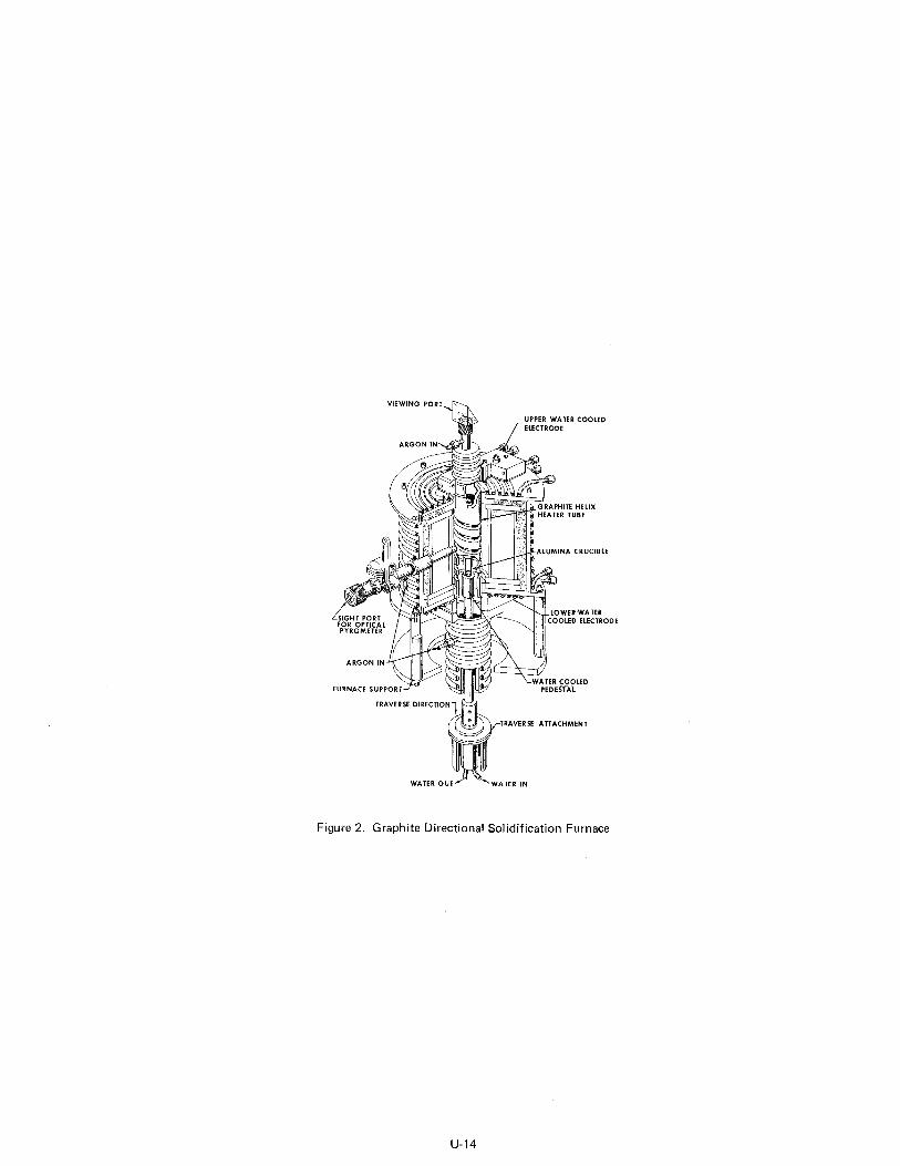
Figure 2. Graphite Directional Solidification Furnace
u-14
Y > i= v kf ki
0 500 1000 1500 2000 2500
TEMPERATURE - OF
2200-F
Figure 3. Temperature Dependence of Transverse Shear Strength
40 0 ?
z ii
\?I 30
h v; 10 iii a..- ; 26 4. w ix hiI > -_ t 10 k! (i w
-
0 I I I I ‘ 0 scxi 1000 1.503 2000 2500
TEMPERATURE- F
iii 120 CL
c-3 0
g 80
2 Gl 06 a g 40
_“. -.. q NizAl-NigCb (2 CM/HR)
0 (Co.Cr,Al)-(Cr,Co),C3 (10 CM,‘HR) /
NigAl-NigCb
ir! I IN, 3-J ““:‘, .” ^,., ,n_,”
_-_ ‘t”’ (“--
75’F
2200” F
(Co,Cr,Af)-(Cr,Co), Cg
--C 1 IN. d
75°F
0.250 IN.
1000 F 1500 ‘F
Figure 4. Temperature Dependence of Longitudinal Shear Strength of Ni3Al-Ni3Cb Eutectic Solidified at 2 cm/hr
u-15
iii a m 0 7 k z 2 z
2 w 5
: r V w
it w
50
40
30
20
1c
3 r\ J
-\~
TENSILE TENSILE 8. SWEAR SHEAR ----- ------ )r
FAILURE FAILURE FAILURE
0.2SOIN -
5OO’F 1000 F
Figure 5. Temperature Dependence of Longitudinal Shear Strength of (Co,Cr,Al)-(Cr,Co)7C3 Eutectic Solidified at 10 cm/hr
90
9 80
r-2
0
; 70
vi 2
iz 60 w
d I Ln Y 50
> i=
ii Y 40
30
a
0 0 - NigAl-Ni3Cb (2 CM/HR)
0 - (C0,Cr,Al~-ICr,tc)~c3 (10 CM/HR)
0
0 200 400 600 800 1000
0 0
0 0
0
r
0 .o
0
TEMPERATURE - OF
Figure 6. Temperature Dependence of Longitudinal Thread Shear Strength
U-16
54
48
42
36 6; f
5 30
I-
g 24 0
;; b- 18
12
6
’ 48
0.125 IN. , __ -+-i
42
;; @j 36
I 3 30
+-l 5 24
a s 18
I- 12
6
I ! I I / 1 / h I IA I v r
0 50 100 150 200 250 300 350 550 600 850 900
ANGLE OF TWIST, 0 - DEGREES
Figure 8. Torque vs Angle of Twist for (Co,Cr,Al)-(Cr,Co)7C3 Eutectic Solidified at 10 cm/hr
u-17
-
ITIATION OF CRACKS
0 125 IN
1 I I I I * I 50 100 1.50 200 250 300 350 41
ANGLE OF TWIST, 0 - DEGREES
Figure 7. Torque vs Angle of Twist for Ni3Al-Ni3Cb Eutectic Solidified at 2 cm/hr
31 3
DIA = 0.250 IN.
Figure 9. Ground Flush Head Fastener Shape of the NigAl-Ni$b Eutectic
Figure 10. Cast Single Flush Head Fastener Shapes of the N’i3Al-Ni$b Eutectic
./ /( I
‘_< ” ,Y Dl
v- a” 8 I
-: b %hv* / .%$e&
t t
,+,I ? 1 I % i
DIRECTION
DIRECTION ; : OF OF
i SOLIDIFICATION , SOLIDIFICATION
c : $ * ” 2 .: ,: -c “&DIA ,Y ;
-c ;~DIA
i f 4 4
i ; )I_ “. ” d ” 4 1 84 ” ,+ : P ‘ P
,, *
-+ +-DIA -+ +-DIA .,‘_
DIA
I-I
DIA = 0.250 IN.
U-18
DIRECTION OF SOLlOlFlCATlON
DIA = 0.250 IN.
Figure 11. Cast Double Flush Head Fastener Shape of the Ni3Al-Ni$b Eutectic
.
0.250 IN. DIA
c
AS FORMED - WITH FLASHING AFTER GRINDING HEAD AND MACRO-ETCHING
AROUND FASTENER HEAD FASTENER SURFACE
Figure 12. Creep Formed Flush Head Fastener Shape of the Ni3Al-NigCb Eutecti0 (Macxo)
u-19
I I 1
LO.250 IN. DIA---/
Figure 13. Creep Formed Flush Head Fastener Shape of the Ni3Al-Ni3Cb Eutectic (Micro)
DIA = 0.250 IN.
-------DIA ------I
s+BiAt. I /
Figure 14. Creep F :orl med Flush Head Fastener Shape of the (Co,Cr,Al)-(Cr,Co)7C3 Eutectic
u-20
50
40
ix
,” 30 a
rc
2 z t; 20
%
2 M YY V 5 10
E! k
0 0
I I I I I I I I I 20 40 60 80 1
0 - DEGREES
0
Fiqure 15. Room Temperature Shear Strength Evaluation of Ground Fastener Shapes of Ni3Al-Ni3Cb Eutectic Solidified at 2 cm/hr
T NixAl-Ni$b (2 CM/M) LONGITUDINAL-RUPTURE (SMOOTH SPECIMEN)
IO
STRESS-RUPTURE LIFE - HOURS
Figure 16. Stress-Rupture Life vs Stress at 2000 F