Directional spool valves, direct operated, with solenoid ... · Manual override, optional ......
24
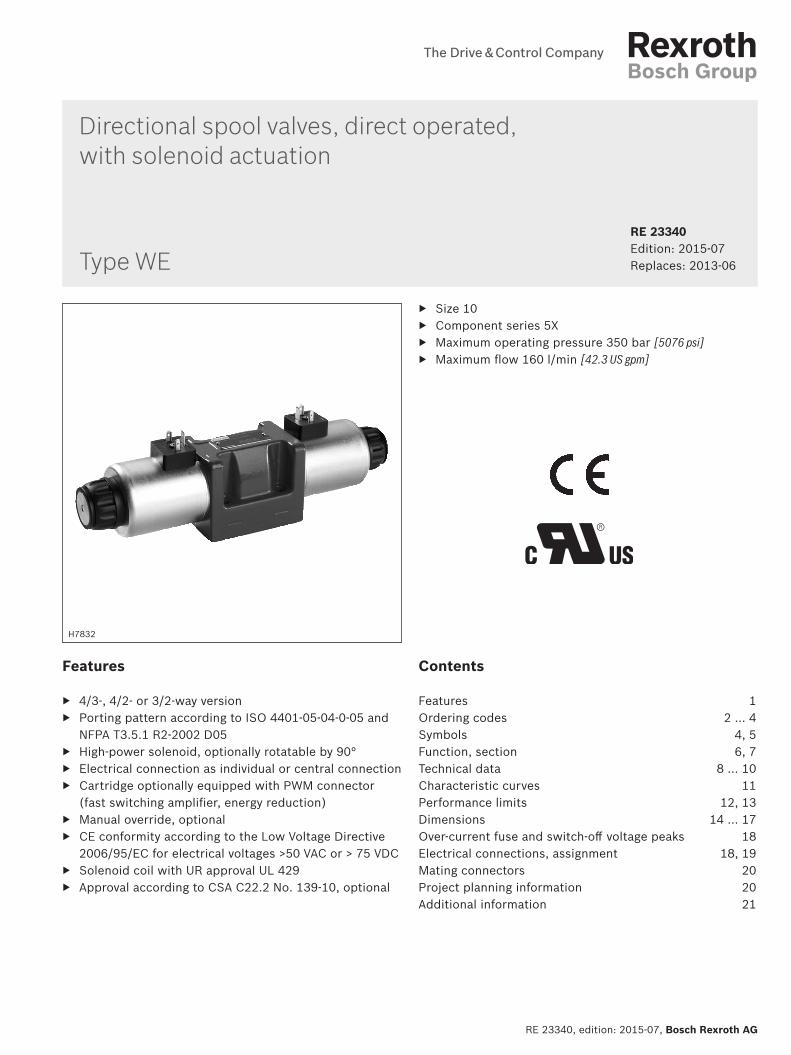
RE 23340, edition: 2015-07, Bosch Rexroth AG Directional spool valves, direct operated, with solenoid actuation Features ▶ 4/3-, 4/2- or 3/2-way version ▶ Porting pattern according to ISO 4401-05-04-0-05 and NFPA T3.5.1 R2-2002 D05 ▶ High-power solenoid, optionally rotatable by 90° ▶ Electrical connection as individual or central connection ▶ Cartridge optionally equipped with PWM connector (fast switching amplifier, energy reduction) ▶ Manual override, optional ▶ CE conformity according to the Low Voltage Directive 2006/95/EC for electrical voltages >50 VAC or > 75 VDC ▶ Solenoid coil with UR approval UL 429 ▶ Approval according to CSA C22.2 No. 139-10, optional Contents Features 1 Ordering codes 2 … 4 Symbols 4, 5 Function, section 6, 7 Technical data 8 … 10 Characteristic curves 11 Performance limits 12, 13 Dimensions 14 … 17 Over-current fuse and switch-off voltage peaks 18 Electrical connections, assignment 18, 19 Mating connectors 20 Project planning information 20 Additional information 21 ▶ Size 10 ▶ Component series 5X ▶ Maximum operating pressure 350 bar [5076 psi] ▶ Maximum flow 160 l/min [42.3 US gpm] RE 23340 Edition: 2015-07 Replaces: 2013-06 H7832 Type WE
-
Upload
phungkhuong -
Category
Documents
-
view
225 -
download
0
Transcript of Directional spool valves, direct operated, with solenoid ... · Manual override, optional ......
RE 23340 edition 2015-07 Bosch Rexroth AG
Directional spool valves direct operated with solenoid actuation
Features
43- 42- or 32-way version Porting pattern according to ISO 4401-05-04-0-05 and
NFPA T351 R2-2002 D05 High-power solenoid optionally rotatable by 90deg Electrical connection as individual or central connection Cartridge optionally equipped with PWM connector
(fast switching amplifier energy reduction) Manual override optional CE conformity according to the Low Voltage Directive
200695EC for electrical voltages gt50 VAC or gt 75 VDC Solenoid coil with UR approval UL 429 Approval according to CSA C222 No 139-10 optional
Contents
Features 1Ordering codes 2 hellip 4Symbols 4 5Function section 6 7Technical data 8 hellip 10Characteristic curves 11Performance limits 12 13Dimensions 14 hellip 17Over-current fuse and switch-off voltage peaks 18Electrical connections assignment 18 19Mating connectors 20Project planning information 20Additional information 21
Size 10 Component series 5X Maximum operating pressure 350 bar [5076 psi] Maximum flow 160 lmin [423 US gpm]
RE 23340thinspEdition 2015-07Replaces 2013-06
H7832
Type WE
Inhalt
Features 1Contents 1Ordering codes 2Ordering codes 3Ordering codes 4Symbols 4Symbols 5Function section 6Function section 7Technical data (For application outside these parameters please consult us) 8Technical data (For application outside these parameters please consult us) 9Technical data (For application outside these parameters please consult us) 10Characteristic curves (measured with HLP46 ϑOil = 40 plusmn 5 degC [104 plusmn 9 degF]) 11Performance limits (measured with HLP46 ϑOil = 40 plusmn 5 degC [104 plusmn 9 degF]) 12Performance limits (measured with HLP46 ϑOil = 40 plusmn 5 degC [104 plusmn 9 degF]) 13Dimensions Individual connection (dimensions in mm [inch]) 14Dimensions Central connection (dimensions in mm [inch]) 15Dimensions Manual overrides (dimensions in mm [inch]) 16Dimensions 17Over-current fuse and switch-off voltage peaks 18Electrical connections assignment ndash individual connection 18Electrical connections assignment ndash central connection 19Mating connectors according to DIN EN 175301-803 20Project planning information 20Additional information 21Notes 22Notes 23Notes 24
222 WE | Directional spool valve
Bosch Rexroth AG RE 23340 edition 2015-07
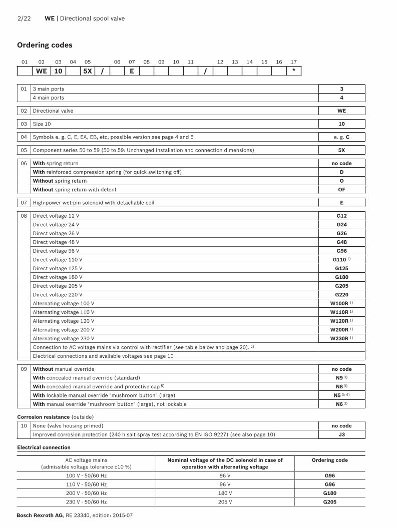
Ordering codes
01 3 main ports 34 main ports 4
02 Directional valve WE
03 Size 10 10
04 Symbols e g C E EA EB etc possible version see page 4 and 5 e g C
05 Component series 50 to 59 (50 to 59 Unchanged installation and connection dimensions) 5X
06 With spring return no codeWith reinforced compression spring (for quick switching off) DWithout spring return OWithout spring return with detent OF
07 High-power wet-pin solenoid with detachable coil E
08 Direct voltage 12 V G12Direct voltage 24 V G24Direct voltage 26 V G26Direct voltage 48 V G48Direct voltage 96 V G96Direct voltage 110 V G110 1)
Direct voltage 125 V G125Direct voltage 180 V G180Direct voltage 205 V G205Direct voltage 220 V G220Alternating voltage 100 V W100R 1)
Alternating voltage 110 V W110R 1)
Alternating voltage 120 V W120R 1)
Alternating voltage 200 V W200R 1)
Alternating voltage 230 V W230R 1)
Connection to AC voltage mains via control with rectifier (see table below and page 20) 2)
Electrical connections and available voltages see page 10
09 Without manual override no codeWith concealed manual override (standard) N9 3)
With concealed manual override and protective cap 5) N8 3)
With lockable manual override mushroom button (large) N5 3 4)
With manual override mushroom button (large) not lockable N6 3)
Corrosion resistance (outside)
10 None (valve housing primed) no codeImproved corrosion protection (240 h salt spray test according to EN ISO 9227) (see also page 10) J3
Electrical connection
01 02 03 04 05 06 07 08 09 10 11 12 13 14 15 16 17
WE 10 5X E
AC voltage mains (admissible voltage tolerance plusmn10 )
Nominal voltage of the DC solenoid in case of operation with alternating voltage
Ordering code
100 V - 5060 Hz 96 V G96110 V - 5060 Hz 96 V G96200 V - 5060 Hz 180 V G180230 V - 5060 Hz 205 V G205
Directional spool valve | WE 322
RE 23340 edition 2015-07 Bosch Rexroth AG
Ordering codes
01 02 03 04 05 06 07 08 09 10 11 12 13 14 15 16 17
WE 10 5X E
11 Individual connectionWithout mating connector connector according to DIN EN 175301-803 K4 6)
Without mating connector connector according to DIN EN 175301-803 (coil with potted-in connector base and sealing element to valve housing (IP67))
K4K 6 7)
Without mating connector 4-pole with connector M12x1 according to IEC 60947-5-2 integrated interference pro-tection circuit and status LED
K72L 6)
Without mating connector connector AMP Junior-Timer C4Z 6)
Central connectionCable entry at the cover with indicator light DLCentral plug-in connection at the cover with indicator light (without mating connector) connector according to DIN EN 175201-804 DK6LWithout mating connector threaded connection 12-14 NPT DALCable gland at the cover with indicator light and cable bridge at the ground connection DJLMini-change connector 5-pole DK25LAdditional electrical connections and available voltages see page 10
Switching time increase12 Without switching time increase no code
With switching time increase (only with symbol 73 not for version D with reinforced compression spring more information upon request)
A12
13 Without throttle insert no codeWith throttle insert 8 9)
Port Throttle Oslash in mm [inch]
08 [0031] 10 [0039] 12 [0047]
P = B08 = B10 = B12A = H08 = H10 = H12B = R08 = R10 = R12A and B = N08 = N10 = N12T 10) = X08 = X10 = X12
Further throttle insert diameters upon request
Control spool play 14 Standard no code
Minimum (to be selected in case of reduced leakage rarr higher level of oil cleanliness recommended) T06Increased (to be selected in case of a hydraulic fluidenvironment temperature difference gt25 K rarr increased internal leakage) T12
Seal material15 NBR seals M
FKM seals VSeals for HFC hydraulic fluids MHLow-temperature version MTObserve compatibility of seals with hydraulic fluid used
16 Approval according to CSA C222 No 139-10 CSAPorting pattern according to ANSI B939 (if solenoid a is energized channel P is connected to A) AN
17 Further details in the plain text
Explanation of the footnotes see page 4 NoticeFor directional spool valves size 10 with spool position monitor-ing see data sheet 23352
422 WE | Directional spool valve
Bosch Rexroth AG RE 23340 edition 2015-07
Symbols
NoticeRepresentation according to DIN ISO 1219-1Hydraulic interim positions are shown by dashes
7) Recommended for mobile applications with additional sealing between solenoid coil and pole tube
8) When the admissible valve performance limits are exceeded throttle inserts are to be installed (for performance limits see page 12 and 13)
9) Not with low-temperature version MT10) If throttle inserts are used in channel T the pressure in the
working ports and for connection to the tank chambers must not exceed 210 bar
Ordering codes
1) Only for version Central connection2) Only for version Individual connection3) The manual override cannot be allocated a safety function The
manual override units may only be used up to a tank pressure of 50 bar
4) With tank pressures above 50 bar it cannot be guaranteed that the valve remains in the position switched by the N5 manual override
5) Protective cap must be removed prior to actuation6) Mating connectors separate order see page 20 and
data sheet 08006
13
Directional spool valve | WE 522
RE 23340 edition 2015-07 Bosch Rexroth AG
Symbols
1) Example Symbol E with spool position a ordering code EA Symbol E with spool position b ordering code EB
2) Flow cross-section see page 8
Notices Representation according to DIN ISO 1219-1 Hydraulic interim positions are shown by dashes
Other symbols upon request
7
4 1 3 4
TA TBBPA
5 5
622 WE | Directional spool valve
Bosch Rexroth AG RE 23340 edition 2015-07
Function section
The directional valve type WE is a solenoid-actuated direc-tional spool valve that can be used as electro-magnetic component It controls the start stop and direction of a flowThe directional valve basically consists of housing (1) one or two electronic solenoids (2) the control spool (3) and the return springs (4)In the de-energized condition the control spool (3) is held in the central position or in the initial position by the return springs (4) (except for version O) If the wet-pin electronic solenoid (2) is energized the control spool (3) moves out of its rest position into the required end position In this way the required direction of flow according to the selected symbol is released
After the electronic solenoid (2) has been switched off the control spool (3) is pushed back into its central posi-tion or into its initial position (except for valves with OF detent and valves without type O spring)A manual override (6) allows for the manual switching of the valve without solenoid energization
To ensure proper functioning make sure that the pres-sure chamber of the solenoid is filled with oil
More functions see page 7
Type WE 10 Ehellip
Throttle insert BUsing a throttle insert (7) in channels P A B or T the flow resistance at the valve can be increased Its use is required when due to prevailing operating conditions flows occur during the switching processes which exceed the perfor-mance limit of the valve
A
a
Directional spool valve | WE 722
RE 23340 edition 2015-07 Bosch Rexroth AG
Function section
Type WE 10 OFhellip
Without spring return O (only possible with symbols A C and D)This version is a directional valve with 2 spool positions and 2 electronic solenoids without detent The valve with-out spring return at the control spool (3) has no defined basic position in the de-energized condition
Without spring return with OF detent (only possible with symbols A C and D)This version is a directional valve with 2 spool positions and 2 electronic solenoids with detent The detents are used to fix the control spool (3) in the relevant spool position During operation continuous application of current to the electronic solenoid can thus be omitted which contributes to energy-efficient operation
NoticePressure peaks in the tank line to two or several valves can result in unintended movement of the control spool in the case of valves with detent We therefore recom-mend that separate return lines be provided or a check valve installed in the tank line
822 WE | Directional spool valve
Bosch Rexroth AG RE 23340 edition 2015-07
Technical data (For application outside these parameters please consult us)
1) With suspended installation higher sensitivity to contamination Horizontal installation is recommended
2) In case of use at low temperatures see project planning infor-mation on page 20
hydraulic
Maximum operating pressure 2) ndash Ports A B P bar [psi] 350 [5076]
ndash Port T bar [psi] 210 [3050] Tank pressure (standard) With symbols A and B port T must be used as leakage oil con-nection if the operating pressure exceeds the maximum admissi-ble tank pressure
Maximum flow lmin [US gpm] 160 [423]
Flow cross-section (spool position 0)
ndash Symbol Q mm2 Approx 6 of nominal cross-section
ndash Symbol W mm2 Approx 3 of nominal cross-section
Hydraulic fluid See table below
Hydraulic fluid temperature range (at the valve working ports)
degC [degF] ndash20 hellip +80 [ndash4 hellip +176] (NBR seals)ndash15 hellip +80 [+5 hellip +176] (FKM seals)ndash20 hellip +50 [ndash4 hellip +122] (HFC hydraulic fluid)ndash40 hellip +50 [ndash40 hellip +122] (low-temperature version)
Viscosity range mm2s [SUS] 28 hellip 500 [35 hellip 2320]
Maximum admissible degree of contamination of the hydraulic fluid - cleanliness class according to ISO 4406 (c)
Class 201815 3)
generalWeight Individual connection Central connection
ndash Valve with one solenoid kg [lbs] 39 [86] 40 [88]
ndash Valve with two solenoids kg [lbs] 55 [121] 56 [123]
Installation position Any 1)
Ambient tempera-ture range
ndash Standard version degC [degF] ndash20 hellip +70 [ndash4 hellip +158] (NBR seals)ndash15 hellip +70 [+5 hellip +158] (FKM seals)
ndash Version for HFC hydraulic fluid degC [degF] ndash20 hellip +50 [ndash4 hellip +122]
ndash Low-temperature version 2) degC [degF] ndash40 hellip +50 [ndash40 hellip +122]
Storage temperature range degC [degF] ndash20 hellip +50 [ndash4 hellip +122]
MTTFd values according to EN ISO 13849 Years 300 (for further details see data sheet 08012)
3) The cleanliness classes specified for the components must be adhered to in hydraulic systems Effective filtration prevents faults and at the same time increases the life cycle of the components
Available filters can be found at wwwboschrexrothcomfilter
Hydraulic fluid Classification Suitable sealing materials
Standards Data sheet
Mineral oils HL HLP HLPD HVLP HVLPD NBR FKM DIN 51524 90220
Bio-degradable insoluble in water HETG NBR FKM ISO 15380 90221
HEES FKM
soluble in water HEPG FKM ISO 15380
Flame-resistant water-free HFDU HFDR FKM ISO 12922 90222
containing water HFC (Fuchs Hydrotherm 46M Petrofer Ultra Safe 620)
NBR ISO 12922 90223
Important information on hydraulic fluids For more information and data on the use of other hydraulic fluids please refer to the data sheets above or contact us
There may be limitations regarding the technical valve data (tem-perature pressure range life cycle maintenance intervals etc)
The flash point of the hydraulic fluid used must be 40 K higher than the maximum solenoid surface temperature
Flame-resistant ndash containing water ndash Maximum pressure differential per control edge 50 bar ndash Pressure pre-loading at the tank port gt20 of the pressure differential otherwise increased cavitation
ndash Life cycle as compared to operation with mineral oil HL HLP 50 to 100
Bio-degradable and flame-resistant When using hydraulic fluids that are simultaneously zinc-solving zinc may accumulate (700 mg zinc per pole tube)
Directional spool valve | WE 922
RE 23340 edition 2015-07 Bosch Rexroth AG
Technical data (For application outside these parameters please consult us)
electricVoltage type Direct voltage Alternating voltage
Nominal voltage according to VDE 0580 (ordering code see page 2 and 10)
V 12 24 26 48 96 110 125 180 205 220
Possible with central connec-tion or via rectifier 4)
Voltage tolerance (nominal voltage) plusmn10
Nominal power according to VDE 0580 W 40 5)
Duty cycle (ED) 100 (S1 according to VDE 0580)
Switching time 6) ndash ON Pressure change 5 ms 60 hellip 104 7 8)
Pressure change 95 ms 90 hellip 165 7 8)
ndash OFF Pressure change 5 ms 12 hellip 50 230 hellip 330
Pressure change 95 ms 48 hellip 104 250 hellip 360
Switching time according to ISO 6403 9)
ndash ON 45 hellip 60
ndash OFF 20 hellip 30 250 hellip 360
Maximum switching frequency 1h 15000 7200
Protection class according to DIN EN 60529 See page 10
Protection class according to VDE 0580 See page 10
Maximum surface temperature of the coil 10) degC [degF] 140 [284]
Insulation class VDE 0580 F
Electrical protection Every solenoid must be protected individually using a suitable fuse with tripping characteristics K (inductive loads) The valve must be installed on a surface that is included in the equipoten-tial bonding
Protective earthing conductor and screening See connector pin assignment (CE-compliant installation) page 18 and 19
Conformity CE according to Low-Voltage Directive 200695EC tested according to DIN EN 60204-1 (VDE0113-1) 2010-05 and DIN VDE 0580 2000-07
4) Mating connectors with rectifier see page 20 Possible voltages see page 2 Rectifiers must comply with the relevant standards as well as
the coil performance data With a central connection the rectifier is on the board5) Reduction of the nominal power by approx 40 if a 24 V-coil with
connector switching amplifier type VT-SSBA1-PWM-1XV0025 is used (separate order material no R901290194 see page 20 and data sheet 30362)
6) Measured with flow 80 performance limit and horizontal installation position
7) Not with symbols A B and 738) Reduction of the switching time by approx 50 if a 12 V-coil with
connector switching amplifier type VT-SSBA1-PWM-1XV0015 is used (separate order material no R901265633 see page 20 and data sheet 30362)
9) Measured without flow10) Possible surface temperature gt 50 degC provide contact protection
Notices The solenoid coils must not be painted Actuation of the manual override is only possible up to a tank pressure of approx 50 bar [725 psi] Avoid damage to the bore of the manual override (Special tool for the operation separate order material no R900024943) When the manual override is blocked actuation of the opposite solenoid must be ruled out
The simultaneous actuation of 2 solenoids of one valve must be ruled out
Use cables that are approved for a working temperature above 105 degC [221 degF]
Valves with individual connection and a supply voltage of 12 V or 24 V can be operated with twice the voltage for reducing the switching time For this purpose the voltage has to be reduced to the nominal valve voltage after 100 ms by means of pulse width modulation The maximum admis-sible switching frequency is 3 1s
Due to possible overload of the board valves with central connection must not be operated with twice the voltage
If the standard environmental conditions according to VDE 0580 cannot be provided the valve must be especially protected
Electrical connections see page 10
1022 WE | Directional spool valve
Bosch Rexroth AG RE 23340 edition 2015-07
Technical data (For application outside these parameters please consult us)
11) Only with correctly mounted valve with a mating connector suitable for the protection class
12) Recommended for mobile applications with additional sealing between solenoid coil and pole tube
13) Solenoid coils without Recognized component according to UL 429
14) Possible with version J315) With protection class III a protective extra-low voltage with
isolation transformer (PELV SELV) is to be provided16) Only with professionally designed connection with appropriate
sealing to the central connection17) Connector pin assignment see page 19
When establishing the electrical connection the protective earthing conductor (PE ) has to be connected correctly
Notices The plug-in connectors used are not intended to be plugged in or disconnected during normal operation under load
Operation of the valves only admissible with appropriate and locked mating connector
Electrical connections and available voltages
Connector ordering codes
Ordering codes
Prot
ecti
on c
lass
acc
ord-
ing
to D
IN E
N 6
0529
11)
Prot
ecti
on c
lass
acc
ord-
ing
to V
DE
0580
Direct voltage Alternating voltage
G12
G24
G26
G48
G96
G11
0
G12
5
G18
0
G20
5
G22
0
W10
0R
W11
0R
W12
0R
W20
0R
W23
0R
Indi
vidu
al c
onne
ctio
n
Without mating connector individual connection connector according to DIN EN 175301-803
K4 ndash ndash 13)
ndash ndash ndash ndash ndash IP65 I
K4K 12) 13)
13)
13)
ndash ndash ndash ndash ndash ndash ndash ndash ndash ndash ndash ndash IP65 IP67
I
Without mating connector 4-pole with con-nector M12x1 according to IEC 60947-5-2 integrated interference protection circuit and status LED
K72L ndash 13)
ndash ndash ndash ndash ndash ndash ndash ndash ndash ndash ndash ndash ndash IP65 III15)
Without mating connector connector AMP Junior-Timer
C4Z ndash ndash 13)
ndash ndash ndash ndash ndash ndash ndash ndash ndash ndash ndash ndash IP66 III15)
Cen
tral
con
nect
ion
Without mating connector threaded con-nection 12-14 NPT
DAL ndash ndash ndash ndash ndash IP65 16)
I
Central plug-in connection at the cover with indicator light (without mating connec-tor) with connector according to DIN EN 175201-804
DK6L17) ndash ndash ndash ndash IP65 I
Cable gland at the cover with indicator light (terminal area 6 hellip 12 mm [023 hellip 047 inch])
DL14) ndash ndash ndash ndash IP65 I
Cable gland at the cover with indicator light and cable bridge at the ground connection
DJL14) ndash ndash ndash ndash ndash ndash ndash ndash ndash IP65 I
Mini-change connector 5-pole according to ANSIB9355M-1981
DK25L17) ndash ndash ndash ndash ndash ndash ndash ndash IP65 I
Directional spool valve | WE 1122
RE 23340 edition 2015-07 Bosch Rexroth AG
∆p-qV characteristic curves
Flow in lmin [US gpm] rarr
Flow in lmin [US gpm] rarr
Flow in lmin [US gpm] rarr
Pres
sure
diff
eren
tial i
n ba
r [p
si] rarr
Pres
sure
diff
eren
tial i
n ba
r [p
si] rarr
Pres
sure
diff
eren
tial i
n ba
r [p
si] rarr
Symbol
Direction of flow
P ndash A P ndash B A ndash T B ndash T
A B 6 6 ndash ndash
A73 B73 23 23 ndash ndash
C 1 2 5 7
D 2 2 5 7
D73 25 26 26 27
E 17 16 19 21
E67 4 4 11 24
E73 17 18 21 21
F 2 3 22 23
G 4 4 24 24
G73 18 18 24 24
H 14 14 20 21
H73 14 14 6 9
J 3 3 9 11
J73 22 21 23 24
L 3 3 9 9
L73 22 10 11 24
M 14 14 6 8
P 17 14 20 23
Q 16 17 4 8
R 18 21 18 24
R73 24 24 23 24
T 18 4 10 24
U 3 3 6 11
U10 Upon request
U73 22 22 23 24
V 17 17 18 20
W Upon request
X7 Upon request
X34 Upon request
Y 17 16 18 21
Y11 3 2 4 9
Y73 26 26 26 28
Central position
Symbol
Direction of flow
P ndash A P ndash B B ndash T A ndash T P ndash T
H 12 12 13 13 15
Characteristic curves (measured with HLP46 ϑOil = 40 plusmn 5 degC [104 plusmn 9 degF])
200
300
100
50
0 10 20 30 40 50 60
[0] [4] [8] [12]
[1000]
[2000]
[3000]
[4000]
150
250
350
70 80 90 100 110 120
[16] [20] [24] [28]
[5000]
400
130 140 150 160
[30] [32] [34]
[5802]
[423]
0
16
15
1817
12
13
14
13
1
1
19 20
1222 WE | Directional spool valve
Bosch Rexroth AG RE 23340 edition 2015-07
Performance limits (measured with HLP46 ϑOil = 40 plusmn 5 degC [104 plusmn 9 degF])
NoticeThe specified performance limits are valid for operation with two directions of flow (e g from P to A and simulta-neous return flow from B to T)Due to the flow forces acting within the valves the admissible performance limit may be considerably lower
with only one direction of flow (e g from P to A while port B is blocked)In such cases of application please consult usThe performance limits were determined when the solenoids were at operating temperature at 10 undervoltage and without tank preloading
Ope
ratin
g pr
essu
re in
bar
[psi]
rarrO
pera
ting
pres
sure
in b
ar [p
si] rarr
Flow in lmin [US gpm] rarr
Flow in lmin [US gpm] rarr
Characteristic curve
Symbol
1 L
2 A
3 B
4 Y
5 E73 Q
6 F
7 G73
8 M V
9 P
10 A73
11 H73
Characteristic curve
Symbol
1 L
12 AO
13 J
14 H
15 D73
16 B73
17 Y11
18 C D E73
19 E67
20 G
Spring side
Solenoid side
200
300
100
50
0 10 20 30 40 50 60
[0] [4] [8] [12]
[1000]
[2000]
[3000]
[4000]
150
250
350
70 80 90 100 110 120
[16] [20] [24] [28]
[5000]
400
130 140 150 160
[30] [32] [34]
[5802]
[423]
0
23
22
21
25
24
24
27
27
26
21
200
300
100
50
0 10 20 30 40 50 60
[0] [4] [8] [12]
[1000]
[2000]
[3000]
[4000]
150
250
350
70 80 90 100 110 120
[16] [20] [24] [28]
[5000]
400
130 140 150 160
[30] [32] [34]
[5802]
[423]
0
28
31
32
3435
29
30
31
2833
Directional spool valve | WE 1322
RE 23340 edition 2015-07 Bosch Rexroth AG
Performance limits (measured with HLP46 ϑOil = 40 plusmn 5 degC [104 plusmn 9 degF])
NoticeThe specified performance limits are valid for operation with two directions of flow (e g from P to A and simulta-neous return flow from B to T)Due to the flow forces acting within the valves the admissible performance limit may be considerably lower
with only one direction of flow (e g from P to A while port B is blocked)In such cases of application please consult usThe performance limits were determined when the solenoids were at operating temperature at 10 undervoltage and without tank preloading
Ope
ratin
g pr
essu
re in
bar
[psi]
rarrO
pera
ting
pres
sure
in b
ar [p
si] rarr
Flow in lmin [US gpm] rarr
Flow in lmin [US gpm] rarr
Characteristic curve
Symbol
21 A B
22 G73
23 F L73
24 E
25 CO DO
26 J73
27 U
Characteristic curve
Symbol
28 Q
29 V
30 P
31 R
32 R73
33 T
34 U73
35 Y73
Solenoid side
Solenoid side
001100[0000440]
Rzmax 4
Oslash11 Oslash66
TA TBA B
PF1 F2
1511
42
1512
0
191922
4012
802675
30
13 13
10
11 12
51 52 69
161514
12
F3F4
[05
9][4
50
]
[15
7]
[102] [315]
[11
8]
[47
2][0
59]
[295]
70[0
47]
[27
6]
[075]
[363]
51 52
14
[Oslash043] [Oslash026]
80[3
15]
A B
53
15
55
15[0
59]
54
12
[05
9]
12
Oslash150
[Oslash5
91]
126
[49
6]
12
120
[47
2]
20[0
79]
75[295]
111 112
1422 WE | Directional spool valve
Bosch Rexroth AG RE 23340 edition 2015-07
Dimensions Individual connection (dimensions in mm [inch])
Required surface quality of the valve contact surface
Notices Deviating from ISO 4401 port T is called TA and port T1 is called TB in this data sheet
The dimensions are nominal dimensions which are subject to tolerances
Dimensions for manual overrides see page 16Item explanations valve mounting screws and subplates see page 17
13
001100[0000440]
Rzmax 4
Directional spool valve | WE 1522
RE 23340 edition 2015-07 Bosch Rexroth AG
Dimensions Central connection (dimensions in mm [inch])
Required surface quality of the valve contact surface
NoticeThe dimensions are nominal dimensions which are subject to tolerances
Special points with version DAL and DL Version DL is only suitable for permanently
installed cables Lines must be routed in a pull-relieved manner
Minimum line cross-section 075 mm2 (AWG 18) With a maximum line cross-section of 150 mm2
(AWG 16) and if wire end ferrules are used wire end ferrules without flange must be crimped to a maximum cross-section of 15 mm x 2 mm (trapezoi-dal crimp) using an appropriate tool (e g PZ 65 co Weidmuumlller) to ensure that they fit into the printed circuit board terminals
Before crimping the wires have to be stripped to 9-1 mm [035ndash0039 inch]
For the corresponding line cross-section 1) wire end ferrules without flange (according to DIN 46228-1) with a length of 8 mm [031 inch] are to be used
For the earthing connection ring cable lugs accord-ing to DIN 46234-4-1 are to be used tightening torque MA = 175 Nm [129 ft-lbs] plusmn10
Dimensions for manual overrides see page 16Item explanations valve mounting screws and subplates see page 17
1) 075 mm2 (AWG 20) 100 mm2 (AWG 18) 150 mm2 (AWG 16)
NoticeThe lines must be finely stranded
001100[0000440]
Rzmax 4
1622 WE | Directional spool valve
Bosch Rexroth AG RE 23340 edition 2015-07
Dimensions Manual overrides (dimensions in mm [inch])
Required surface quality of the valve contact surface
Item explanations valve mounting screws and subplates see page 17
NoticeThe dimensions are nominal dimensions which are subject to tolerances
2 Version without and with concealed manual override N9 (standard)
3 Version with concealed manual override and protective cap N8 (The protective cap must be removed prior to actuation)
4 Version with manual override N5 and N6
Directional spool valve | WE 1722
RE 23340 edition 2015-07 Bosch Rexroth AG
Dimensions
Subplates according to data sheet 45054 (separate order) G 6601 (G38) G 6701 (G12) G 53401 (G34)G 6612 (SAE-6 916-18) 1) G 6712 (SAE-8 34-16) 1) G 53412 (SAE-12 1-116-12) 1)
1) Upon request
Valve mounting screws (separate order)4 metric hexagon socket head cap screws ISO 4762 - M6 x 40 - 109-flZn-240h-L (friction coefficient micrototal = 009 to 014) tightening torque MA = 125 Nm [92 ft-lbs] plusmn10 material no R913000058 or 4 hexagon socket head cap screws ISO 4762 - M6 x 40 - 109 (self procurement) (friction coefficient micrototal = 012 to 017) tightening torque MA = 155 Nm [114 ft-lbs] plusmn10
4 UNC hexagon socket head cap screws 14-20 UNC x 1-12 ASTM-A574 (friction coefficient) micrototal = 019 to 024) tightening torque MA = 25 Nm [184 ft-lbs] plusmn15 (friction coefficient micrototal = 012 to 017) tightening torque MA = 19 Nm [140 ft-lbs] plusmn10 material no R978800710
With different friction coefficients the tightening torques are to be adjusted accordingly
11 Solenoid a12 Solenoid b
2 Version without and with concealed manual override N9 (standard)
3 Version with concealed manual override and protective cap N8 (The protective cap must be removed prior to actuation)
4 Version with manual override N5 and N651 Mating connector without circuitry for connector K4
(separate order see page 20 and data sheet 08006)52 Mating connector without circuitry for connector K4K
(separate order see data sheet 08006)53 Mating connector angled with M12x1 plug-in connection and
status LED for connector K72L (separate order see data sheet 08006)
54 Double mating connector withoutwith circuitry for connec-tor K4 (separate order see data sheet 08006)
55 Mating connector (AMP Junior Timer) for connector C4Z (separate order see data sheet 08006)
6 Mating connector with circuitry for connector K4 (separate order see page 20 and data sheet 08006)
71 Cable gland Pg 16 DL (terminal area 6 hellip 12 mm [024 hellip 047 inch]) lock nut tightening torque MA = 33 Nm [243 ft-lbs] plusmn10
72 Central connection box DAL 12 NPT tightening torque MA = 5 Nm [369 ft-lbs] plusmn10 sealing by sealant
73 Connector DK6L and DK25L81 Mating connector for connector DK6L (separate order
material no R900002803 see data sheet 08006)82 Mini-change connector 5-pole for connector DK25L
(separate order material no R900057631)9 Name plate
10 Identical seal rings for ports A B P TA TB111 Plug screw for valves with one solenoid on B side112 Plug screw for valves with one solenoid on A side
12 Space required to remove the mating connectorangled socket
13 Space required to remove the coil14 Mounting nut tightening torque MA = 145plusmn15 Nm
[1069plusmn11 ft-lbs]15 Porting pattern according to ISO 4401-05-04-0-05 and
NFPA T351 R2-2002 D05
16 Connection TB can only be used in connection with sepa-rately produced bore
17 CoverNotice The valve may only be operated with properly mounted cover Tightening torque of the cover screws MA = 10 Nm [074 ft-lbs] plusmn10 Prior to opening the frame it must be ensured that the valve has no voltage
1822 WE | Directional spool valve
Bosch Rexroth AG RE 23340 edition 2015-07
Over-current fuse and switch-off voltage peaks
Maximum admissible overvoltages according to DIN EN 60664-12008-01 (VDE 0110-1) (overvoltage category II)
Electrical connection 1)Nominal voltage
in VRated current
in AMaximum admissible switch-off
overvoltage in V 2)
K4 K4K DAL D6KL DL 12 372 500K4 K4K K72L DAL D6KL DL DJL DK25L 24 174 500K4 C4Z 26 170 500K4 48 057 500K4 DAL D6KL DL DK25L 96 047 500D6KL DL DJL 110 041 500K4 125 022 500K4 C4Z 180 028 500K4 DAL D6KL DL 205 022 500K4 DAL D6KL DL 220 021 500
NoticeWhen solenoid coils are switched off voltage peaks result which may cause faults or damage in the connected control electronics We therefore recommend limiting them to 2 x nominal voltage by means of an interference protection circuit It must be noted that a diode switched in an antiparallel form extends the switching off time
Electrical connections assignment ndash individual connection
1) Interference protection circuit integrated2) To be ensured by user circuitry
Electrical connections and coil connection combinations
Connector ordering codes Top view Circuit diagram PinConnections assignment
Connector 3-pole (2+PE) according to DIN EN 175301-803 (IP65)
K4K4K 3)
4)
1
2
1 Solenoid coil polarity-independent2Earthing
Connector 4-pole according to IEC 60947-5-2 M12x1 with suppres-sor diode only 24 V DC integrated interference protection circuit and status LED
K72L
1
2 3
4
+
ndash5
1 Internal bridge23 Solenoid coil GND4 Solenoid coil 24 V DC
supply voltage5 without function
2-pole connector type AMP Junior-Timer rotated by 90deg relative to valve axis
C4Z
1
2
1 Solenoid coil polarity-independent
2
3) Coil with potted-in connector base and sealing element to valve housing (IP67)
4) M3 tightening torque maximum MA max = 05 Nm [037 ft-lbs]
Directional spool valve | WE 1922
RE 23340 edition 2015-07 Bosch Rexroth AG
Electrical connections assignment ndash central connection
Electrical connections and coil connection combinations
Connector ordering codes Top view Circuit diagram PinConnections assignment
Cable gland at the cover with indicator light (terminal area 6 hellip 12 mm [023 hellip 047 inch])
DL
1+2ndash
ldquobrdquo
ldquoardquo
3+4ndash
Dire
ct v
olta
ge
ldquoardquo ldquobrdquo
1+ 3+
2ndash 4ndash2) 1+
Valve solenoid a 1)
2ndash
3+
Valve solenoid b 1)
4ndash
Earthing
Cable gland at the cover with indicator light and cable bridge at the ground connection(terminal area 6 hellip 12 mm [023 hellip 047 inch])
DJL
Alte
rnat
ing
volta
ge
ndash
+
Without mating connector threaded connection 12-14 NPT(terminal area 6 hellip 12 mm [023 hellip 047 inch])
DAL 3)
Central plug-in connection at the cover with indicator light (without mating connector) with connector according to DIN EN 175201-804
DK6L
1+
654ndash3+
2ndashPE
ldquobrdquo
ldquoardquo
1 Valve solenoid a2
3 Valve solenoid b4
5Not used
6
Earthing
Mini-change connector 5-pole according to ANSIB9355M-1981
DK25L
ldquobrdquo
ldquoardquo
1+5ndash
4ndash 2+3
1 Valve solenoid a5
2 Valve solenoid b4
3 Earthing
1) Core marking + rarr red ndash rarr blue
2) Bridge only for version DJL3) Cable gland with NPT thread
NPT
12ldquo
2022 WE | Directional spool valve
Bosch Rexroth AG RE 23340 edition 2015-07
Project planning information
Temperature range and maximum operating pressure in case of use at low temperaturesPort Pressure Temperature range in degC [degF]ndash P A B T Static 100 bar [1450 psi] ndash40 hellip ndash35 [ndash40 hellip ndash31]ndash P A B Dynamic from 100 bar [1450 psi] to 350 bar [5076 psi] in linear form as a
function of the temperaturendash35 hellip ndash30 [ndash31 hellip ndash22]
ndash T Dynamic from 100 bar [1450 psi] to 210 bar [3050 psi] in linear form as a function of the temperature
ndash35 hellip ndash30 [ndash31 hellip ndash22]
ndash P A B T Maximum operating pressure ndash30 hellip +50 [ndash22 hellip 122]
Cartridge with PWM connector according to data sheet 30362
Depending on the control spool increasing the perfor-mance limit is possible
With version G24 (energy saving) the coil tempera-ture is reduced by ge 30 degC for 100 duty cycle
Mating connectors according to DIN EN 175301-803
Energy savings and fast switching 1)
Details see data sheet 30362Material number
Type VT-SSBA1-PWM-1XV0015 as fast switching amplifier
(switching time reduction by approx 50 ) 2)
Type VT-SSBA1-PWM-1XV0025 for energy reduction
(energy savings of approx 40 ) 3)
ab Black R901265633 R901290194
For details and more mating connectors see data sheet 08006
Port Valv
e si
de
Color
Material no
Without circuitryWith indicator light
12 240 VWith rectifier 12 240 V
With indicator light and Zener diode suppression circuit
24 V
M16 x 15a Gray R901017010 ndash ndash ndash
ab Black R901017011 R901017022 R901017025 R901017026
12 NPT (Pg16)
a Redbrown R900004823 ndash ndash ndash
ab Black R900011039 R900057453 R900842566 ndash
1) Only with symbols C D E E67 J J2 Y and Y11 not for version D with reinforced compression spring
2) Only available for G12 and K4K4K version3) Only available for G24 and K4K4K version
Directional spool valve | WE 2122
RE 23340 edition 2015-07 Bosch Rexroth AG
Additional information
Subplates Data sheet 45054 Hydraulic fluids on mineral oil basis Data sheet 90220 Environmentally compatible hydraulic fluids Data sheet 90221 Flame-resistant water-free hydraulic fluids Data sheet 90222 Connector switching amplifier type VT-SSBA1 Data sheet 30362 Directional spool and seat valves with electrical actuation and M12x1 plug-in
connectionData sheet 08010
Reliability characteristics according to EN ISO 13849 Data sheet 08012 Hydraulic valves for industrial applications Data sheet 07600-B CE declaration of conformity according to Low-voltage Directive 200695EC Upon request Selection of filters wwwboschrexrothcomfilter Information on available spare parts wwwboschrexrothcomspc
Bosch Rexroth AG RE 23340 edition 2015-07
2222 WE | Directional spool valve
Bosch Rexroth AG HydraulicsZum Eisengieszliger 197816 Lohr am Main Germany Phone +49 (0) 93 52thinspthinsp18-0 documentationboschrexrothde wwwboschrexrothde
copy This document as well as the data specifications and other information set forth in it are the exclusive property of Bosch Rexroth AG It may not be reproduced or given to third parties without its consentThe data specified above only serve to describe the product No statements concerning a certain condition or suitability for a certain application can be derived from our information The information given does not release the user from the obligation of own judgment and verification It must be remembered that our products are subject to a natural process of wear and aging
Notes
Bosch Rexroth AG HydraulicsZum Eisengieszliger 197816 Lohr am Main Germany Phone +49 (0) 93 52thinspthinsp18-0 documentationboschrexrothde wwwboschrexrothde
copy This document as well as the data specifications and other information set forth in it are the exclusive property of Bosch Rexroth AG It may not be reproduced or given to third parties without its consentThe data specified above only serve to describe the product No statements concerning a certain condition or suitability for a certain application can be derived from our information The information given does not release the user from the obligation of own judgment and verification It must be remembered that our products are subject to a natural process of wear and aging
Directional spool valve | WE 2322
RE 23340 edition 2015-07 Bosch Rexroth AG
Notes
Bosch Rexroth AG RE 23340 edition 2015-07
2422 WE | Directional spool valve
Notes
- Features
- Contents
- Ordering codes
- Symbols
- Function section
- Technical data
- Characteristic curves
- Performance limits
- Dimensions
- Over-current fuse and switch-off voltage peaks
- Electrical connections assignment ndash individual connection
- Mating connectors
- Project planning information
- Additional information
-
222 WE | Directional spool valve
Bosch Rexroth AG RE 23340 edition 2015-07
Ordering codes
01 3 main ports 34 main ports 4
02 Directional valve WE
03 Size 10 10
04 Symbols e g C E EA EB etc possible version see page 4 and 5 e g C
05 Component series 50 to 59 (50 to 59 Unchanged installation and connection dimensions) 5X
06 With spring return no codeWith reinforced compression spring (for quick switching off) DWithout spring return OWithout spring return with detent OF
07 High-power wet-pin solenoid with detachable coil E
08 Direct voltage 12 V G12Direct voltage 24 V G24Direct voltage 26 V G26Direct voltage 48 V G48Direct voltage 96 V G96Direct voltage 110 V G110 1)
Direct voltage 125 V G125Direct voltage 180 V G180Direct voltage 205 V G205Direct voltage 220 V G220Alternating voltage 100 V W100R 1)
Alternating voltage 110 V W110R 1)
Alternating voltage 120 V W120R 1)
Alternating voltage 200 V W200R 1)
Alternating voltage 230 V W230R 1)
Connection to AC voltage mains via control with rectifier (see table below and page 20) 2)
Electrical connections and available voltages see page 10
09 Without manual override no codeWith concealed manual override (standard) N9 3)
With concealed manual override and protective cap 5) N8 3)
With lockable manual override mushroom button (large) N5 3 4)
With manual override mushroom button (large) not lockable N6 3)
Corrosion resistance (outside)
10 None (valve housing primed) no codeImproved corrosion protection (240 h salt spray test according to EN ISO 9227) (see also page 10) J3
Electrical connection
01 02 03 04 05 06 07 08 09 10 11 12 13 14 15 16 17
WE 10 5X E
AC voltage mains (admissible voltage tolerance plusmn10 )
Nominal voltage of the DC solenoid in case of operation with alternating voltage
Ordering code
100 V - 5060 Hz 96 V G96110 V - 5060 Hz 96 V G96200 V - 5060 Hz 180 V G180230 V - 5060 Hz 205 V G205
Directional spool valve | WE 322
RE 23340 edition 2015-07 Bosch Rexroth AG
Ordering codes
01 02 03 04 05 06 07 08 09 10 11 12 13 14 15 16 17
WE 10 5X E
11 Individual connectionWithout mating connector connector according to DIN EN 175301-803 K4 6)
Without mating connector connector according to DIN EN 175301-803 (coil with potted-in connector base and sealing element to valve housing (IP67))
K4K 6 7)
Without mating connector 4-pole with connector M12x1 according to IEC 60947-5-2 integrated interference pro-tection circuit and status LED
K72L 6)
Without mating connector connector AMP Junior-Timer C4Z 6)
Central connectionCable entry at the cover with indicator light DLCentral plug-in connection at the cover with indicator light (without mating connector) connector according to DIN EN 175201-804 DK6LWithout mating connector threaded connection 12-14 NPT DALCable gland at the cover with indicator light and cable bridge at the ground connection DJLMini-change connector 5-pole DK25LAdditional electrical connections and available voltages see page 10
Switching time increase12 Without switching time increase no code
With switching time increase (only with symbol 73 not for version D with reinforced compression spring more information upon request)
A12
13 Without throttle insert no codeWith throttle insert 8 9)
Port Throttle Oslash in mm [inch]
08 [0031] 10 [0039] 12 [0047]
P = B08 = B10 = B12A = H08 = H10 = H12B = R08 = R10 = R12A and B = N08 = N10 = N12T 10) = X08 = X10 = X12
Further throttle insert diameters upon request
Control spool play 14 Standard no code
Minimum (to be selected in case of reduced leakage rarr higher level of oil cleanliness recommended) T06Increased (to be selected in case of a hydraulic fluidenvironment temperature difference gt25 K rarr increased internal leakage) T12
Seal material15 NBR seals M
FKM seals VSeals for HFC hydraulic fluids MHLow-temperature version MTObserve compatibility of seals with hydraulic fluid used
16 Approval according to CSA C222 No 139-10 CSAPorting pattern according to ANSI B939 (if solenoid a is energized channel P is connected to A) AN
17 Further details in the plain text
Explanation of the footnotes see page 4 NoticeFor directional spool valves size 10 with spool position monitor-ing see data sheet 23352
422 WE | Directional spool valve
Bosch Rexroth AG RE 23340 edition 2015-07
Symbols
NoticeRepresentation according to DIN ISO 1219-1Hydraulic interim positions are shown by dashes
7) Recommended for mobile applications with additional sealing between solenoid coil and pole tube
8) When the admissible valve performance limits are exceeded throttle inserts are to be installed (for performance limits see page 12 and 13)
9) Not with low-temperature version MT10) If throttle inserts are used in channel T the pressure in the
working ports and for connection to the tank chambers must not exceed 210 bar
Ordering codes
1) Only for version Central connection2) Only for version Individual connection3) The manual override cannot be allocated a safety function The
manual override units may only be used up to a tank pressure of 50 bar
4) With tank pressures above 50 bar it cannot be guaranteed that the valve remains in the position switched by the N5 manual override
5) Protective cap must be removed prior to actuation6) Mating connectors separate order see page 20 and
data sheet 08006
13
Directional spool valve | WE 522
RE 23340 edition 2015-07 Bosch Rexroth AG
Symbols
1) Example Symbol E with spool position a ordering code EA Symbol E with spool position b ordering code EB
2) Flow cross-section see page 8
Notices Representation according to DIN ISO 1219-1 Hydraulic interim positions are shown by dashes
Other symbols upon request
7
4 1 3 4
TA TBBPA
5 5
622 WE | Directional spool valve
Bosch Rexroth AG RE 23340 edition 2015-07
Function section
The directional valve type WE is a solenoid-actuated direc-tional spool valve that can be used as electro-magnetic component It controls the start stop and direction of a flowThe directional valve basically consists of housing (1) one or two electronic solenoids (2) the control spool (3) and the return springs (4)In the de-energized condition the control spool (3) is held in the central position or in the initial position by the return springs (4) (except for version O) If the wet-pin electronic solenoid (2) is energized the control spool (3) moves out of its rest position into the required end position In this way the required direction of flow according to the selected symbol is released
After the electronic solenoid (2) has been switched off the control spool (3) is pushed back into its central posi-tion or into its initial position (except for valves with OF detent and valves without type O spring)A manual override (6) allows for the manual switching of the valve without solenoid energization
To ensure proper functioning make sure that the pres-sure chamber of the solenoid is filled with oil
More functions see page 7
Type WE 10 Ehellip
Throttle insert BUsing a throttle insert (7) in channels P A B or T the flow resistance at the valve can be increased Its use is required when due to prevailing operating conditions flows occur during the switching processes which exceed the perfor-mance limit of the valve
A
a
Directional spool valve | WE 722
RE 23340 edition 2015-07 Bosch Rexroth AG
Function section
Type WE 10 OFhellip
Without spring return O (only possible with symbols A C and D)This version is a directional valve with 2 spool positions and 2 electronic solenoids without detent The valve with-out spring return at the control spool (3) has no defined basic position in the de-energized condition
Without spring return with OF detent (only possible with symbols A C and D)This version is a directional valve with 2 spool positions and 2 electronic solenoids with detent The detents are used to fix the control spool (3) in the relevant spool position During operation continuous application of current to the electronic solenoid can thus be omitted which contributes to energy-efficient operation
NoticePressure peaks in the tank line to two or several valves can result in unintended movement of the control spool in the case of valves with detent We therefore recom-mend that separate return lines be provided or a check valve installed in the tank line
822 WE | Directional spool valve
Bosch Rexroth AG RE 23340 edition 2015-07
Technical data (For application outside these parameters please consult us)
1) With suspended installation higher sensitivity to contamination Horizontal installation is recommended
2) In case of use at low temperatures see project planning infor-mation on page 20
hydraulic
Maximum operating pressure 2) ndash Ports A B P bar [psi] 350 [5076]
ndash Port T bar [psi] 210 [3050] Tank pressure (standard) With symbols A and B port T must be used as leakage oil con-nection if the operating pressure exceeds the maximum admissi-ble tank pressure
Maximum flow lmin [US gpm] 160 [423]
Flow cross-section (spool position 0)
ndash Symbol Q mm2 Approx 6 of nominal cross-section
ndash Symbol W mm2 Approx 3 of nominal cross-section
Hydraulic fluid See table below
Hydraulic fluid temperature range (at the valve working ports)
degC [degF] ndash20 hellip +80 [ndash4 hellip +176] (NBR seals)ndash15 hellip +80 [+5 hellip +176] (FKM seals)ndash20 hellip +50 [ndash4 hellip +122] (HFC hydraulic fluid)ndash40 hellip +50 [ndash40 hellip +122] (low-temperature version)
Viscosity range mm2s [SUS] 28 hellip 500 [35 hellip 2320]
Maximum admissible degree of contamination of the hydraulic fluid - cleanliness class according to ISO 4406 (c)
Class 201815 3)
generalWeight Individual connection Central connection
ndash Valve with one solenoid kg [lbs] 39 [86] 40 [88]
ndash Valve with two solenoids kg [lbs] 55 [121] 56 [123]
Installation position Any 1)
Ambient tempera-ture range
ndash Standard version degC [degF] ndash20 hellip +70 [ndash4 hellip +158] (NBR seals)ndash15 hellip +70 [+5 hellip +158] (FKM seals)
ndash Version for HFC hydraulic fluid degC [degF] ndash20 hellip +50 [ndash4 hellip +122]
ndash Low-temperature version 2) degC [degF] ndash40 hellip +50 [ndash40 hellip +122]
Storage temperature range degC [degF] ndash20 hellip +50 [ndash4 hellip +122]
MTTFd values according to EN ISO 13849 Years 300 (for further details see data sheet 08012)
3) The cleanliness classes specified for the components must be adhered to in hydraulic systems Effective filtration prevents faults and at the same time increases the life cycle of the components
Available filters can be found at wwwboschrexrothcomfilter
Hydraulic fluid Classification Suitable sealing materials
Standards Data sheet
Mineral oils HL HLP HLPD HVLP HVLPD NBR FKM DIN 51524 90220
Bio-degradable insoluble in water HETG NBR FKM ISO 15380 90221
HEES FKM
soluble in water HEPG FKM ISO 15380
Flame-resistant water-free HFDU HFDR FKM ISO 12922 90222
containing water HFC (Fuchs Hydrotherm 46M Petrofer Ultra Safe 620)
NBR ISO 12922 90223
Important information on hydraulic fluids For more information and data on the use of other hydraulic fluids please refer to the data sheets above or contact us
There may be limitations regarding the technical valve data (tem-perature pressure range life cycle maintenance intervals etc)
The flash point of the hydraulic fluid used must be 40 K higher than the maximum solenoid surface temperature
Flame-resistant ndash containing water ndash Maximum pressure differential per control edge 50 bar ndash Pressure pre-loading at the tank port gt20 of the pressure differential otherwise increased cavitation
ndash Life cycle as compared to operation with mineral oil HL HLP 50 to 100
Bio-degradable and flame-resistant When using hydraulic fluids that are simultaneously zinc-solving zinc may accumulate (700 mg zinc per pole tube)
Directional spool valve | WE 922
RE 23340 edition 2015-07 Bosch Rexroth AG
Technical data (For application outside these parameters please consult us)
electricVoltage type Direct voltage Alternating voltage
Nominal voltage according to VDE 0580 (ordering code see page 2 and 10)
V 12 24 26 48 96 110 125 180 205 220
Possible with central connec-tion or via rectifier 4)
Voltage tolerance (nominal voltage) plusmn10
Nominal power according to VDE 0580 W 40 5)
Duty cycle (ED) 100 (S1 according to VDE 0580)
Switching time 6) ndash ON Pressure change 5 ms 60 hellip 104 7 8)
Pressure change 95 ms 90 hellip 165 7 8)
ndash OFF Pressure change 5 ms 12 hellip 50 230 hellip 330
Pressure change 95 ms 48 hellip 104 250 hellip 360
Switching time according to ISO 6403 9)
ndash ON 45 hellip 60
ndash OFF 20 hellip 30 250 hellip 360
Maximum switching frequency 1h 15000 7200
Protection class according to DIN EN 60529 See page 10
Protection class according to VDE 0580 See page 10
Maximum surface temperature of the coil 10) degC [degF] 140 [284]
Insulation class VDE 0580 F
Electrical protection Every solenoid must be protected individually using a suitable fuse with tripping characteristics K (inductive loads) The valve must be installed on a surface that is included in the equipoten-tial bonding
Protective earthing conductor and screening See connector pin assignment (CE-compliant installation) page 18 and 19
Conformity CE according to Low-Voltage Directive 200695EC tested according to DIN EN 60204-1 (VDE0113-1) 2010-05 and DIN VDE 0580 2000-07
4) Mating connectors with rectifier see page 20 Possible voltages see page 2 Rectifiers must comply with the relevant standards as well as
the coil performance data With a central connection the rectifier is on the board5) Reduction of the nominal power by approx 40 if a 24 V-coil with
connector switching amplifier type VT-SSBA1-PWM-1XV0025 is used (separate order material no R901290194 see page 20 and data sheet 30362)
6) Measured with flow 80 performance limit and horizontal installation position
7) Not with symbols A B and 738) Reduction of the switching time by approx 50 if a 12 V-coil with
connector switching amplifier type VT-SSBA1-PWM-1XV0015 is used (separate order material no R901265633 see page 20 and data sheet 30362)
9) Measured without flow10) Possible surface temperature gt 50 degC provide contact protection
Notices The solenoid coils must not be painted Actuation of the manual override is only possible up to a tank pressure of approx 50 bar [725 psi] Avoid damage to the bore of the manual override (Special tool for the operation separate order material no R900024943) When the manual override is blocked actuation of the opposite solenoid must be ruled out
The simultaneous actuation of 2 solenoids of one valve must be ruled out
Use cables that are approved for a working temperature above 105 degC [221 degF]
Valves with individual connection and a supply voltage of 12 V or 24 V can be operated with twice the voltage for reducing the switching time For this purpose the voltage has to be reduced to the nominal valve voltage after 100 ms by means of pulse width modulation The maximum admis-sible switching frequency is 3 1s
Due to possible overload of the board valves with central connection must not be operated with twice the voltage
If the standard environmental conditions according to VDE 0580 cannot be provided the valve must be especially protected
Electrical connections see page 10
1022 WE | Directional spool valve
Bosch Rexroth AG RE 23340 edition 2015-07
Technical data (For application outside these parameters please consult us)
11) Only with correctly mounted valve with a mating connector suitable for the protection class
12) Recommended for mobile applications with additional sealing between solenoid coil and pole tube
13) Solenoid coils without Recognized component according to UL 429
14) Possible with version J315) With protection class III a protective extra-low voltage with
isolation transformer (PELV SELV) is to be provided16) Only with professionally designed connection with appropriate
sealing to the central connection17) Connector pin assignment see page 19
When establishing the electrical connection the protective earthing conductor (PE ) has to be connected correctly
Notices The plug-in connectors used are not intended to be plugged in or disconnected during normal operation under load
Operation of the valves only admissible with appropriate and locked mating connector
Electrical connections and available voltages
Connector ordering codes
Ordering codes
Prot
ecti
on c
lass
acc
ord-
ing
to D
IN E
N 6
0529
11)
Prot
ecti
on c
lass
acc
ord-
ing
to V
DE
0580
Direct voltage Alternating voltage
G12
G24
G26
G48
G96
G11
0
G12
5
G18
0
G20
5
G22
0
W10
0R
W11
0R
W12
0R
W20
0R
W23
0R
Indi
vidu
al c
onne
ctio
n
Without mating connector individual connection connector according to DIN EN 175301-803
K4 ndash ndash 13)
ndash ndash ndash ndash ndash IP65 I
K4K 12) 13)
13)
13)
ndash ndash ndash ndash ndash ndash ndash ndash ndash ndash ndash ndash IP65 IP67
I
Without mating connector 4-pole with con-nector M12x1 according to IEC 60947-5-2 integrated interference protection circuit and status LED
K72L ndash 13)
ndash ndash ndash ndash ndash ndash ndash ndash ndash ndash ndash ndash ndash IP65 III15)
Without mating connector connector AMP Junior-Timer
C4Z ndash ndash 13)
ndash ndash ndash ndash ndash ndash ndash ndash ndash ndash ndash ndash IP66 III15)
Cen
tral
con
nect
ion
Without mating connector threaded con-nection 12-14 NPT
DAL ndash ndash ndash ndash ndash IP65 16)
I
Central plug-in connection at the cover with indicator light (without mating connec-tor) with connector according to DIN EN 175201-804
DK6L17) ndash ndash ndash ndash IP65 I
Cable gland at the cover with indicator light (terminal area 6 hellip 12 mm [023 hellip 047 inch])
DL14) ndash ndash ndash ndash IP65 I
Cable gland at the cover with indicator light and cable bridge at the ground connection
DJL14) ndash ndash ndash ndash ndash ndash ndash ndash ndash IP65 I
Mini-change connector 5-pole according to ANSIB9355M-1981
DK25L17) ndash ndash ndash ndash ndash ndash ndash ndash IP65 I
Directional spool valve | WE 1122
RE 23340 edition 2015-07 Bosch Rexroth AG
∆p-qV characteristic curves
Flow in lmin [US gpm] rarr
Flow in lmin [US gpm] rarr
Flow in lmin [US gpm] rarr
Pres
sure
diff
eren
tial i
n ba
r [p
si] rarr
Pres
sure
diff
eren
tial i
n ba
r [p
si] rarr
Pres
sure
diff
eren
tial i
n ba
r [p
si] rarr
Symbol
Direction of flow
P ndash A P ndash B A ndash T B ndash T
A B 6 6 ndash ndash
A73 B73 23 23 ndash ndash
C 1 2 5 7
D 2 2 5 7
D73 25 26 26 27
E 17 16 19 21
E67 4 4 11 24
E73 17 18 21 21
F 2 3 22 23
G 4 4 24 24
G73 18 18 24 24
H 14 14 20 21
H73 14 14 6 9
J 3 3 9 11
J73 22 21 23 24
L 3 3 9 9
L73 22 10 11 24
M 14 14 6 8
P 17 14 20 23
Q 16 17 4 8
R 18 21 18 24
R73 24 24 23 24
T 18 4 10 24
U 3 3 6 11
U10 Upon request
U73 22 22 23 24
V 17 17 18 20
W Upon request
X7 Upon request
X34 Upon request
Y 17 16 18 21
Y11 3 2 4 9
Y73 26 26 26 28
Central position
Symbol
Direction of flow
P ndash A P ndash B B ndash T A ndash T P ndash T
H 12 12 13 13 15
Characteristic curves (measured with HLP46 ϑOil = 40 plusmn 5 degC [104 plusmn 9 degF])
200
300
100
50
0 10 20 30 40 50 60
[0] [4] [8] [12]
[1000]
[2000]
[3000]
[4000]
150
250
350
70 80 90 100 110 120
[16] [20] [24] [28]
[5000]
400
130 140 150 160
[30] [32] [34]
[5802]
[423]
0
16
15
1817
12
13
14
13
1
1
19 20
1222 WE | Directional spool valve
Bosch Rexroth AG RE 23340 edition 2015-07
Performance limits (measured with HLP46 ϑOil = 40 plusmn 5 degC [104 plusmn 9 degF])
NoticeThe specified performance limits are valid for operation with two directions of flow (e g from P to A and simulta-neous return flow from B to T)Due to the flow forces acting within the valves the admissible performance limit may be considerably lower
with only one direction of flow (e g from P to A while port B is blocked)In such cases of application please consult usThe performance limits were determined when the solenoids were at operating temperature at 10 undervoltage and without tank preloading
Ope
ratin
g pr
essu
re in
bar
[psi]
rarrO
pera
ting
pres
sure
in b
ar [p
si] rarr
Flow in lmin [US gpm] rarr
Flow in lmin [US gpm] rarr
Characteristic curve
Symbol
1 L
2 A
3 B
4 Y
5 E73 Q
6 F
7 G73
8 M V
9 P
10 A73
11 H73
Characteristic curve
Symbol
1 L
12 AO
13 J
14 H
15 D73
16 B73
17 Y11
18 C D E73
19 E67
20 G
Spring side
Solenoid side
200
300
100
50
0 10 20 30 40 50 60
[0] [4] [8] [12]
[1000]
[2000]
[3000]
[4000]
150
250
350
70 80 90 100 110 120
[16] [20] [24] [28]
[5000]
400
130 140 150 160
[30] [32] [34]
[5802]
[423]
0
23
22
21
25
24
24
27
27
26
21
200
300
100
50
0 10 20 30 40 50 60
[0] [4] [8] [12]
[1000]
[2000]
[3000]
[4000]
150
250
350
70 80 90 100 110 120
[16] [20] [24] [28]
[5000]
400
130 140 150 160
[30] [32] [34]
[5802]
[423]
0
28
31
32
3435
29
30
31
2833
Directional spool valve | WE 1322
RE 23340 edition 2015-07 Bosch Rexroth AG
Performance limits (measured with HLP46 ϑOil = 40 plusmn 5 degC [104 plusmn 9 degF])
NoticeThe specified performance limits are valid for operation with two directions of flow (e g from P to A and simulta-neous return flow from B to T)Due to the flow forces acting within the valves the admissible performance limit may be considerably lower
with only one direction of flow (e g from P to A while port B is blocked)In such cases of application please consult usThe performance limits were determined when the solenoids were at operating temperature at 10 undervoltage and without tank preloading
Ope
ratin
g pr
essu
re in
bar
[psi]
rarrO
pera
ting
pres
sure
in b
ar [p
si] rarr
Flow in lmin [US gpm] rarr
Flow in lmin [US gpm] rarr
Characteristic curve
Symbol
21 A B
22 G73
23 F L73
24 E
25 CO DO
26 J73
27 U
Characteristic curve
Symbol
28 Q
29 V
30 P
31 R
32 R73
33 T
34 U73
35 Y73
Solenoid side
Solenoid side
001100[0000440]
Rzmax 4
Oslash11 Oslash66
TA TBA B
PF1 F2
1511
42
1512
0
191922
4012
802675
30
13 13
10
11 12
51 52 69
161514
12
F3F4
[05
9][4
50
]
[15
7]
[102] [315]
[11
8]
[47
2][0
59]
[295]
70[0
47]
[27
6]
[075]
[363]
51 52
14
[Oslash043] [Oslash026]
80[3
15]
A B
53
15
55
15[0
59]
54
12
[05
9]
12
Oslash150
[Oslash5
91]
126
[49
6]
12
120
[47
2]
20[0
79]
75[295]
111 112
1422 WE | Directional spool valve
Bosch Rexroth AG RE 23340 edition 2015-07
Dimensions Individual connection (dimensions in mm [inch])
Required surface quality of the valve contact surface
Notices Deviating from ISO 4401 port T is called TA and port T1 is called TB in this data sheet
The dimensions are nominal dimensions which are subject to tolerances
Dimensions for manual overrides see page 16Item explanations valve mounting screws and subplates see page 17
13
001100[0000440]
Rzmax 4
Directional spool valve | WE 1522
RE 23340 edition 2015-07 Bosch Rexroth AG
Dimensions Central connection (dimensions in mm [inch])
Required surface quality of the valve contact surface
NoticeThe dimensions are nominal dimensions which are subject to tolerances
Special points with version DAL and DL Version DL is only suitable for permanently
installed cables Lines must be routed in a pull-relieved manner
Minimum line cross-section 075 mm2 (AWG 18) With a maximum line cross-section of 150 mm2
(AWG 16) and if wire end ferrules are used wire end ferrules without flange must be crimped to a maximum cross-section of 15 mm x 2 mm (trapezoi-dal crimp) using an appropriate tool (e g PZ 65 co Weidmuumlller) to ensure that they fit into the printed circuit board terminals
Before crimping the wires have to be stripped to 9-1 mm [035ndash0039 inch]
For the corresponding line cross-section 1) wire end ferrules without flange (according to DIN 46228-1) with a length of 8 mm [031 inch] are to be used
For the earthing connection ring cable lugs accord-ing to DIN 46234-4-1 are to be used tightening torque MA = 175 Nm [129 ft-lbs] plusmn10
Dimensions for manual overrides see page 16Item explanations valve mounting screws and subplates see page 17
1) 075 mm2 (AWG 20) 100 mm2 (AWG 18) 150 mm2 (AWG 16)
NoticeThe lines must be finely stranded
001100[0000440]
Rzmax 4
1622 WE | Directional spool valve
Bosch Rexroth AG RE 23340 edition 2015-07
Dimensions Manual overrides (dimensions in mm [inch])
Required surface quality of the valve contact surface
Item explanations valve mounting screws and subplates see page 17
NoticeThe dimensions are nominal dimensions which are subject to tolerances
2 Version without and with concealed manual override N9 (standard)
3 Version with concealed manual override and protective cap N8 (The protective cap must be removed prior to actuation)
4 Version with manual override N5 and N6
Directional spool valve | WE 1722
RE 23340 edition 2015-07 Bosch Rexroth AG
Dimensions
Subplates according to data sheet 45054 (separate order) G 6601 (G38) G 6701 (G12) G 53401 (G34)G 6612 (SAE-6 916-18) 1) G 6712 (SAE-8 34-16) 1) G 53412 (SAE-12 1-116-12) 1)
1) Upon request
Valve mounting screws (separate order)4 metric hexagon socket head cap screws ISO 4762 - M6 x 40 - 109-flZn-240h-L (friction coefficient micrototal = 009 to 014) tightening torque MA = 125 Nm [92 ft-lbs] plusmn10 material no R913000058 or 4 hexagon socket head cap screws ISO 4762 - M6 x 40 - 109 (self procurement) (friction coefficient micrototal = 012 to 017) tightening torque MA = 155 Nm [114 ft-lbs] plusmn10
4 UNC hexagon socket head cap screws 14-20 UNC x 1-12 ASTM-A574 (friction coefficient) micrototal = 019 to 024) tightening torque MA = 25 Nm [184 ft-lbs] plusmn15 (friction coefficient micrototal = 012 to 017) tightening torque MA = 19 Nm [140 ft-lbs] plusmn10 material no R978800710
With different friction coefficients the tightening torques are to be adjusted accordingly
11 Solenoid a12 Solenoid b
2 Version without and with concealed manual override N9 (standard)
3 Version with concealed manual override and protective cap N8 (The protective cap must be removed prior to actuation)
4 Version with manual override N5 and N651 Mating connector without circuitry for connector K4
(separate order see page 20 and data sheet 08006)52 Mating connector without circuitry for connector K4K
(separate order see data sheet 08006)53 Mating connector angled with M12x1 plug-in connection and
status LED for connector K72L (separate order see data sheet 08006)
54 Double mating connector withoutwith circuitry for connec-tor K4 (separate order see data sheet 08006)
55 Mating connector (AMP Junior Timer) for connector C4Z (separate order see data sheet 08006)
6 Mating connector with circuitry for connector K4 (separate order see page 20 and data sheet 08006)
71 Cable gland Pg 16 DL (terminal area 6 hellip 12 mm [024 hellip 047 inch]) lock nut tightening torque MA = 33 Nm [243 ft-lbs] plusmn10
72 Central connection box DAL 12 NPT tightening torque MA = 5 Nm [369 ft-lbs] plusmn10 sealing by sealant
73 Connector DK6L and DK25L81 Mating connector for connector DK6L (separate order
material no R900002803 see data sheet 08006)82 Mini-change connector 5-pole for connector DK25L
(separate order material no R900057631)9 Name plate
10 Identical seal rings for ports A B P TA TB111 Plug screw for valves with one solenoid on B side112 Plug screw for valves with one solenoid on A side
12 Space required to remove the mating connectorangled socket
13 Space required to remove the coil14 Mounting nut tightening torque MA = 145plusmn15 Nm
[1069plusmn11 ft-lbs]15 Porting pattern according to ISO 4401-05-04-0-05 and
NFPA T351 R2-2002 D05
16 Connection TB can only be used in connection with sepa-rately produced bore
17 CoverNotice The valve may only be operated with properly mounted cover Tightening torque of the cover screws MA = 10 Nm [074 ft-lbs] plusmn10 Prior to opening the frame it must be ensured that the valve has no voltage
1822 WE | Directional spool valve
Bosch Rexroth AG RE 23340 edition 2015-07
Over-current fuse and switch-off voltage peaks
Maximum admissible overvoltages according to DIN EN 60664-12008-01 (VDE 0110-1) (overvoltage category II)
Electrical connection 1)Nominal voltage
in VRated current
in AMaximum admissible switch-off
overvoltage in V 2)
K4 K4K DAL D6KL DL 12 372 500K4 K4K K72L DAL D6KL DL DJL DK25L 24 174 500K4 C4Z 26 170 500K4 48 057 500K4 DAL D6KL DL DK25L 96 047 500D6KL DL DJL 110 041 500K4 125 022 500K4 C4Z 180 028 500K4 DAL D6KL DL 205 022 500K4 DAL D6KL DL 220 021 500
NoticeWhen solenoid coils are switched off voltage peaks result which may cause faults or damage in the connected control electronics We therefore recommend limiting them to 2 x nominal voltage by means of an interference protection circuit It must be noted that a diode switched in an antiparallel form extends the switching off time
Electrical connections assignment ndash individual connection
1) Interference protection circuit integrated2) To be ensured by user circuitry
Electrical connections and coil connection combinations
Connector ordering codes Top view Circuit diagram PinConnections assignment
Connector 3-pole (2+PE) according to DIN EN 175301-803 (IP65)
K4K4K 3)
4)
1
2
1 Solenoid coil polarity-independent2Earthing
Connector 4-pole according to IEC 60947-5-2 M12x1 with suppres-sor diode only 24 V DC integrated interference protection circuit and status LED
K72L
1
2 3
4
+
ndash5
1 Internal bridge23 Solenoid coil GND4 Solenoid coil 24 V DC
supply voltage5 without function
2-pole connector type AMP Junior-Timer rotated by 90deg relative to valve axis
C4Z
1
2
1 Solenoid coil polarity-independent
2
3) Coil with potted-in connector base and sealing element to valve housing (IP67)
4) M3 tightening torque maximum MA max = 05 Nm [037 ft-lbs]
Directional spool valve | WE 1922
RE 23340 edition 2015-07 Bosch Rexroth AG
Electrical connections assignment ndash central connection
Electrical connections and coil connection combinations
Connector ordering codes Top view Circuit diagram PinConnections assignment
Cable gland at the cover with indicator light (terminal area 6 hellip 12 mm [023 hellip 047 inch])
DL
1+2ndash
ldquobrdquo
ldquoardquo
3+4ndash
Dire
ct v
olta
ge
ldquoardquo ldquobrdquo
1+ 3+
2ndash 4ndash2) 1+
Valve solenoid a 1)
2ndash
3+
Valve solenoid b 1)
4ndash
Earthing
Cable gland at the cover with indicator light and cable bridge at the ground connection(terminal area 6 hellip 12 mm [023 hellip 047 inch])
DJL
Alte
rnat
ing
volta
ge
ndash
+
Without mating connector threaded connection 12-14 NPT(terminal area 6 hellip 12 mm [023 hellip 047 inch])
DAL 3)
Central plug-in connection at the cover with indicator light (without mating connector) with connector according to DIN EN 175201-804
DK6L
1+
654ndash3+
2ndashPE
ldquobrdquo
ldquoardquo
1 Valve solenoid a2
3 Valve solenoid b4
5Not used
6
Earthing
Mini-change connector 5-pole according to ANSIB9355M-1981
DK25L
ldquobrdquo
ldquoardquo
1+5ndash
4ndash 2+3
1 Valve solenoid a5
2 Valve solenoid b4
3 Earthing
1) Core marking + rarr red ndash rarr blue
2) Bridge only for version DJL3) Cable gland with NPT thread
NPT
12ldquo
2022 WE | Directional spool valve
Bosch Rexroth AG RE 23340 edition 2015-07
Project planning information
Temperature range and maximum operating pressure in case of use at low temperaturesPort Pressure Temperature range in degC [degF]ndash P A B T Static 100 bar [1450 psi] ndash40 hellip ndash35 [ndash40 hellip ndash31]ndash P A B Dynamic from 100 bar [1450 psi] to 350 bar [5076 psi] in linear form as a
function of the temperaturendash35 hellip ndash30 [ndash31 hellip ndash22]
ndash T Dynamic from 100 bar [1450 psi] to 210 bar [3050 psi] in linear form as a function of the temperature
ndash35 hellip ndash30 [ndash31 hellip ndash22]
ndash P A B T Maximum operating pressure ndash30 hellip +50 [ndash22 hellip 122]
Cartridge with PWM connector according to data sheet 30362
Depending on the control spool increasing the perfor-mance limit is possible
With version G24 (energy saving) the coil tempera-ture is reduced by ge 30 degC for 100 duty cycle
Mating connectors according to DIN EN 175301-803
Energy savings and fast switching 1)
Details see data sheet 30362Material number
Type VT-SSBA1-PWM-1XV0015 as fast switching amplifier
(switching time reduction by approx 50 ) 2)
Type VT-SSBA1-PWM-1XV0025 for energy reduction
(energy savings of approx 40 ) 3)
ab Black R901265633 R901290194
For details and more mating connectors see data sheet 08006
Port Valv
e si
de
Color
Material no
Without circuitryWith indicator light
12 240 VWith rectifier 12 240 V
With indicator light and Zener diode suppression circuit
24 V
M16 x 15a Gray R901017010 ndash ndash ndash
ab Black R901017011 R901017022 R901017025 R901017026
12 NPT (Pg16)
a Redbrown R900004823 ndash ndash ndash
ab Black R900011039 R900057453 R900842566 ndash
1) Only with symbols C D E E67 J J2 Y and Y11 not for version D with reinforced compression spring
2) Only available for G12 and K4K4K version3) Only available for G24 and K4K4K version
Directional spool valve | WE 2122
RE 23340 edition 2015-07 Bosch Rexroth AG
Additional information
Subplates Data sheet 45054 Hydraulic fluids on mineral oil basis Data sheet 90220 Environmentally compatible hydraulic fluids Data sheet 90221 Flame-resistant water-free hydraulic fluids Data sheet 90222 Connector switching amplifier type VT-SSBA1 Data sheet 30362 Directional spool and seat valves with electrical actuation and M12x1 plug-in
connectionData sheet 08010
Reliability characteristics according to EN ISO 13849 Data sheet 08012 Hydraulic valves for industrial applications Data sheet 07600-B CE declaration of conformity according to Low-voltage Directive 200695EC Upon request Selection of filters wwwboschrexrothcomfilter Information on available spare parts wwwboschrexrothcomspc
Bosch Rexroth AG RE 23340 edition 2015-07
2222 WE | Directional spool valve
Bosch Rexroth AG HydraulicsZum Eisengieszliger 197816 Lohr am Main Germany Phone +49 (0) 93 52thinspthinsp18-0 documentationboschrexrothde wwwboschrexrothde
copy This document as well as the data specifications and other information set forth in it are the exclusive property of Bosch Rexroth AG It may not be reproduced or given to third parties without its consentThe data specified above only serve to describe the product No statements concerning a certain condition or suitability for a certain application can be derived from our information The information given does not release the user from the obligation of own judgment and verification It must be remembered that our products are subject to a natural process of wear and aging
Notes
Bosch Rexroth AG HydraulicsZum Eisengieszliger 197816 Lohr am Main Germany Phone +49 (0) 93 52thinspthinsp18-0 documentationboschrexrothde wwwboschrexrothde
copy This document as well as the data specifications and other information set forth in it are the exclusive property of Bosch Rexroth AG It may not be reproduced or given to third parties without its consentThe data specified above only serve to describe the product No statements concerning a certain condition or suitability for a certain application can be derived from our information The information given does not release the user from the obligation of own judgment and verification It must be remembered that our products are subject to a natural process of wear and aging
Directional spool valve | WE 2322
RE 23340 edition 2015-07 Bosch Rexroth AG
Notes
Bosch Rexroth AG RE 23340 edition 2015-07
2422 WE | Directional spool valve
Notes
- Features
- Contents
- Ordering codes
- Symbols
- Function section
- Technical data
- Characteristic curves
- Performance limits
- Dimensions
- Over-current fuse and switch-off voltage peaks
- Electrical connections assignment ndash individual connection
- Mating connectors
- Project planning information
- Additional information
-
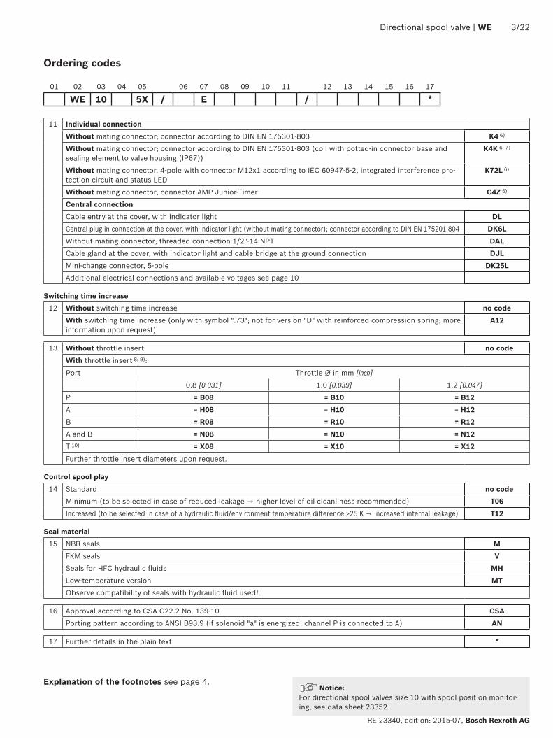
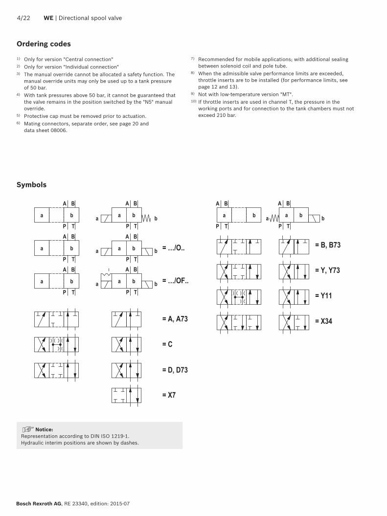
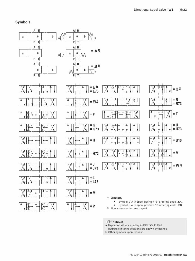
13
Directional spool valve | WE 522
RE 23340 edition 2015-07 Bosch Rexroth AG
Symbols
1) Example Symbol E with spool position a ordering code EA Symbol E with spool position b ordering code EB
2) Flow cross-section see page 8
Notices Representation according to DIN ISO 1219-1 Hydraulic interim positions are shown by dashes
Other symbols upon request
7
4 1 3 4
TA TBBPA
5 5
622 WE | Directional spool valve
Bosch Rexroth AG RE 23340 edition 2015-07
Function section
The directional valve type WE is a solenoid-actuated direc-tional spool valve that can be used as electro-magnetic component It controls the start stop and direction of a flowThe directional valve basically consists of housing (1) one or two electronic solenoids (2) the control spool (3) and the return springs (4)In the de-energized condition the control spool (3) is held in the central position or in the initial position by the return springs (4) (except for version O) If the wet-pin electronic solenoid (2) is energized the control spool (3) moves out of its rest position into the required end position In this way the required direction of flow according to the selected symbol is released
After the electronic solenoid (2) has been switched off the control spool (3) is pushed back into its central posi-tion or into its initial position (except for valves with OF detent and valves without type O spring)A manual override (6) allows for the manual switching of the valve without solenoid energization
To ensure proper functioning make sure that the pres-sure chamber of the solenoid is filled with oil
More functions see page 7
Type WE 10 Ehellip
Throttle insert BUsing a throttle insert (7) in channels P A B or T the flow resistance at the valve can be increased Its use is required when due to prevailing operating conditions flows occur during the switching processes which exceed the perfor-mance limit of the valve
A
a
Directional spool valve | WE 722
RE 23340 edition 2015-07 Bosch Rexroth AG
Function section
Type WE 10 OFhellip
Without spring return O (only possible with symbols A C and D)This version is a directional valve with 2 spool positions and 2 electronic solenoids without detent The valve with-out spring return at the control spool (3) has no defined basic position in the de-energized condition
Without spring return with OF detent (only possible with symbols A C and D)This version is a directional valve with 2 spool positions and 2 electronic solenoids with detent The detents are used to fix the control spool (3) in the relevant spool position During operation continuous application of current to the electronic solenoid can thus be omitted which contributes to energy-efficient operation
NoticePressure peaks in the tank line to two or several valves can result in unintended movement of the control spool in the case of valves with detent We therefore recom-mend that separate return lines be provided or a check valve installed in the tank line
822 WE | Directional spool valve
Bosch Rexroth AG RE 23340 edition 2015-07
Technical data (For application outside these parameters please consult us)
1) With suspended installation higher sensitivity to contamination Horizontal installation is recommended
2) In case of use at low temperatures see project planning infor-mation on page 20
hydraulic
Maximum operating pressure 2) ndash Ports A B P bar [psi] 350 [5076]
ndash Port T bar [psi] 210 [3050] Tank pressure (standard) With symbols A and B port T must be used as leakage oil con-nection if the operating pressure exceeds the maximum admissi-ble tank pressure
Maximum flow lmin [US gpm] 160 [423]
Flow cross-section (spool position 0)
ndash Symbol Q mm2 Approx 6 of nominal cross-section
ndash Symbol W mm2 Approx 3 of nominal cross-section
Hydraulic fluid See table below
Hydraulic fluid temperature range (at the valve working ports)
degC [degF] ndash20 hellip +80 [ndash4 hellip +176] (NBR seals)ndash15 hellip +80 [+5 hellip +176] (FKM seals)ndash20 hellip +50 [ndash4 hellip +122] (HFC hydraulic fluid)ndash40 hellip +50 [ndash40 hellip +122] (low-temperature version)
Viscosity range mm2s [SUS] 28 hellip 500 [35 hellip 2320]
Maximum admissible degree of contamination of the hydraulic fluid - cleanliness class according to ISO 4406 (c)
Class 201815 3)
generalWeight Individual connection Central connection
ndash Valve with one solenoid kg [lbs] 39 [86] 40 [88]
ndash Valve with two solenoids kg [lbs] 55 [121] 56 [123]
Installation position Any 1)
Ambient tempera-ture range
ndash Standard version degC [degF] ndash20 hellip +70 [ndash4 hellip +158] (NBR seals)ndash15 hellip +70 [+5 hellip +158] (FKM seals)
ndash Version for HFC hydraulic fluid degC [degF] ndash20 hellip +50 [ndash4 hellip +122]
ndash Low-temperature version 2) degC [degF] ndash40 hellip +50 [ndash40 hellip +122]
Storage temperature range degC [degF] ndash20 hellip +50 [ndash4 hellip +122]
MTTFd values according to EN ISO 13849 Years 300 (for further details see data sheet 08012)
3) The cleanliness classes specified for the components must be adhered to in hydraulic systems Effective filtration prevents faults and at the same time increases the life cycle of the components
Available filters can be found at wwwboschrexrothcomfilter
Hydraulic fluid Classification Suitable sealing materials
Standards Data sheet
Mineral oils HL HLP HLPD HVLP HVLPD NBR FKM DIN 51524 90220
Bio-degradable insoluble in water HETG NBR FKM ISO 15380 90221
HEES FKM
soluble in water HEPG FKM ISO 15380
Flame-resistant water-free HFDU HFDR FKM ISO 12922 90222
containing water HFC (Fuchs Hydrotherm 46M Petrofer Ultra Safe 620)
NBR ISO 12922 90223
Important information on hydraulic fluids For more information and data on the use of other hydraulic fluids please refer to the data sheets above or contact us
There may be limitations regarding the technical valve data (tem-perature pressure range life cycle maintenance intervals etc)
The flash point of the hydraulic fluid used must be 40 K higher than the maximum solenoid surface temperature
Flame-resistant ndash containing water ndash Maximum pressure differential per control edge 50 bar ndash Pressure pre-loading at the tank port gt20 of the pressure differential otherwise increased cavitation
ndash Life cycle as compared to operation with mineral oil HL HLP 50 to 100
Bio-degradable and flame-resistant When using hydraulic fluids that are simultaneously zinc-solving zinc may accumulate (700 mg zinc per pole tube)
Directional spool valve | WE 922
RE 23340 edition 2015-07 Bosch Rexroth AG
Technical data (For application outside these parameters please consult us)
electricVoltage type Direct voltage Alternating voltage
Nominal voltage according to VDE 0580 (ordering code see page 2 and 10)
V 12 24 26 48 96 110 125 180 205 220
Possible with central connec-tion or via rectifier 4)
Voltage tolerance (nominal voltage) plusmn10
Nominal power according to VDE 0580 W 40 5)
Duty cycle (ED) 100 (S1 according to VDE 0580)
Switching time 6) ndash ON Pressure change 5 ms 60 hellip 104 7 8)
Pressure change 95 ms 90 hellip 165 7 8)
ndash OFF Pressure change 5 ms 12 hellip 50 230 hellip 330
Pressure change 95 ms 48 hellip 104 250 hellip 360
Switching time according to ISO 6403 9)
ndash ON 45 hellip 60
ndash OFF 20 hellip 30 250 hellip 360
Maximum switching frequency 1h 15000 7200
Protection class according to DIN EN 60529 See page 10
Protection class according to VDE 0580 See page 10
Maximum surface temperature of the coil 10) degC [degF] 140 [284]
Insulation class VDE 0580 F
Electrical protection Every solenoid must be protected individually using a suitable fuse with tripping characteristics K (inductive loads) The valve must be installed on a surface that is included in the equipoten-tial bonding
Protective earthing conductor and screening See connector pin assignment (CE-compliant installation) page 18 and 19
Conformity CE according to Low-Voltage Directive 200695EC tested according to DIN EN 60204-1 (VDE0113-1) 2010-05 and DIN VDE 0580 2000-07
4) Mating connectors with rectifier see page 20 Possible voltages see page 2 Rectifiers must comply with the relevant standards as well as
the coil performance data With a central connection the rectifier is on the board5) Reduction of the nominal power by approx 40 if a 24 V-coil with
connector switching amplifier type VT-SSBA1-PWM-1XV0025 is used (separate order material no R901290194 see page 20 and data sheet 30362)
6) Measured with flow 80 performance limit and horizontal installation position
7) Not with symbols A B and 738) Reduction of the switching time by approx 50 if a 12 V-coil with
connector switching amplifier type VT-SSBA1-PWM-1XV0015 is used (separate order material no R901265633 see page 20 and data sheet 30362)
9) Measured without flow10) Possible surface temperature gt 50 degC provide contact protection
Notices The solenoid coils must not be painted Actuation of the manual override is only possible up to a tank pressure of approx 50 bar [725 psi] Avoid damage to the bore of the manual override (Special tool for the operation separate order material no R900024943) When the manual override is blocked actuation of the opposite solenoid must be ruled out
The simultaneous actuation of 2 solenoids of one valve must be ruled out
Use cables that are approved for a working temperature above 105 degC [221 degF]
Valves with individual connection and a supply voltage of 12 V or 24 V can be operated with twice the voltage for reducing the switching time For this purpose the voltage has to be reduced to the nominal valve voltage after 100 ms by means of pulse width modulation The maximum admis-sible switching frequency is 3 1s
Due to possible overload of the board valves with central connection must not be operated with twice the voltage
If the standard environmental conditions according to VDE 0580 cannot be provided the valve must be especially protected
Electrical connections see page 10
1022 WE | Directional spool valve
Bosch Rexroth AG RE 23340 edition 2015-07
Technical data (For application outside these parameters please consult us)
11) Only with correctly mounted valve with a mating connector suitable for the protection class
12) Recommended for mobile applications with additional sealing between solenoid coil and pole tube
13) Solenoid coils without Recognized component according to UL 429
14) Possible with version J315) With protection class III a protective extra-low voltage with
isolation transformer (PELV SELV) is to be provided16) Only with professionally designed connection with appropriate
sealing to the central connection17) Connector pin assignment see page 19
When establishing the electrical connection the protective earthing conductor (PE ) has to be connected correctly
Notices The plug-in connectors used are not intended to be plugged in or disconnected during normal operation under load
Operation of the valves only admissible with appropriate and locked mating connector
Electrical connections and available voltages
Connector ordering codes
Ordering codes
Prot
ecti
on c
lass
acc
ord-
ing
to D
IN E
N 6
0529
11)
Prot
ecti
on c
lass
acc
ord-
ing
to V
DE
0580
Direct voltage Alternating voltage
G12
G24
G26
G48
G96
G11
0
G12
5
G18
0
G20
5
G22
0
W10
0R
W11
0R
W12
0R
W20
0R
W23
0R
Indi
vidu
al c
onne
ctio
n
Without mating connector individual connection connector according to DIN EN 175301-803
K4 ndash ndash 13)
ndash ndash ndash ndash ndash IP65 I
K4K 12) 13)
13)
13)
ndash ndash ndash ndash ndash ndash ndash ndash ndash ndash ndash ndash IP65 IP67
I
Without mating connector 4-pole with con-nector M12x1 according to IEC 60947-5-2 integrated interference protection circuit and status LED
K72L ndash 13)
ndash ndash ndash ndash ndash ndash ndash ndash ndash ndash ndash ndash ndash IP65 III15)
Without mating connector connector AMP Junior-Timer
C4Z ndash ndash 13)
ndash ndash ndash ndash ndash ndash ndash ndash ndash ndash ndash ndash IP66 III15)
Cen
tral
con
nect
ion
Without mating connector threaded con-nection 12-14 NPT
DAL ndash ndash ndash ndash ndash IP65 16)
I
Central plug-in connection at the cover with indicator light (without mating connec-tor) with connector according to DIN EN 175201-804
DK6L17) ndash ndash ndash ndash IP65 I
Cable gland at the cover with indicator light (terminal area 6 hellip 12 mm [023 hellip 047 inch])
DL14) ndash ndash ndash ndash IP65 I
Cable gland at the cover with indicator light and cable bridge at the ground connection
DJL14) ndash ndash ndash ndash ndash ndash ndash ndash ndash IP65 I
Mini-change connector 5-pole according to ANSIB9355M-1981
DK25L17) ndash ndash ndash ndash ndash ndash ndash ndash IP65 I
Directional spool valve | WE 1122
RE 23340 edition 2015-07 Bosch Rexroth AG
∆p-qV characteristic curves
Flow in lmin [US gpm] rarr
Flow in lmin [US gpm] rarr
Flow in lmin [US gpm] rarr
Pres
sure
diff
eren
tial i
n ba
r [p
si] rarr
Pres
sure
diff
eren
tial i
n ba
r [p
si] rarr
Pres
sure
diff
eren
tial i
n ba
r [p
si] rarr
Symbol
Direction of flow
P ndash A P ndash B A ndash T B ndash T
A B 6 6 ndash ndash
A73 B73 23 23 ndash ndash
C 1 2 5 7
D 2 2 5 7
D73 25 26 26 27
E 17 16 19 21
E67 4 4 11 24
E73 17 18 21 21
F 2 3 22 23
G 4 4 24 24
G73 18 18 24 24
H 14 14 20 21
H73 14 14 6 9
J 3 3 9 11
J73 22 21 23 24
L 3 3 9 9
L73 22 10 11 24
M 14 14 6 8
P 17 14 20 23
Q 16 17 4 8
R 18 21 18 24
R73 24 24 23 24
T 18 4 10 24
U 3 3 6 11
U10 Upon request
U73 22 22 23 24
V 17 17 18 20
W Upon request
X7 Upon request
X34 Upon request
Y 17 16 18 21
Y11 3 2 4 9
Y73 26 26 26 28
Central position
Symbol
Direction of flow
P ndash A P ndash B B ndash T A ndash T P ndash T
H 12 12 13 13 15
Characteristic curves (measured with HLP46 ϑOil = 40 plusmn 5 degC [104 plusmn 9 degF])
200
300
100
50
0 10 20 30 40 50 60
[0] [4] [8] [12]
[1000]
[2000]
[3000]
[4000]
150
250
350
70 80 90 100 110 120
[16] [20] [24] [28]
[5000]
400
130 140 150 160
[30] [32] [34]
[5802]
[423]
0
16
15
1817
12
13
14
13
1
1
19 20
1222 WE | Directional spool valve
Bosch Rexroth AG RE 23340 edition 2015-07
Performance limits (measured with HLP46 ϑOil = 40 plusmn 5 degC [104 plusmn 9 degF])
NoticeThe specified performance limits are valid for operation with two directions of flow (e g from P to A and simulta-neous return flow from B to T)Due to the flow forces acting within the valves the admissible performance limit may be considerably lower
with only one direction of flow (e g from P to A while port B is blocked)In such cases of application please consult usThe performance limits were determined when the solenoids were at operating temperature at 10 undervoltage and without tank preloading
Ope
ratin
g pr
essu
re in
bar
[psi]
rarrO
pera
ting
pres
sure
in b
ar [p
si] rarr
Flow in lmin [US gpm] rarr
Flow in lmin [US gpm] rarr
Characteristic curve
Symbol
1 L
2 A
3 B
4 Y
5 E73 Q
6 F
7 G73
8 M V
9 P
10 A73
11 H73
Characteristic curve
Symbol
1 L
12 AO
13 J
14 H
15 D73
16 B73
17 Y11
18 C D E73
19 E67
20 G
Spring side
Solenoid side
200
300
100
50
0 10 20 30 40 50 60
[0] [4] [8] [12]
[1000]
[2000]
[3000]
[4000]
150
250
350
70 80 90 100 110 120
[16] [20] [24] [28]
[5000]
400
130 140 150 160
[30] [32] [34]
[5802]
[423]
0
23
22
21
25
24
24
27
27
26
21
200
300
100
50
0 10 20 30 40 50 60
[0] [4] [8] [12]
[1000]
[2000]
[3000]
[4000]
150
250
350
70 80 90 100 110 120
[16] [20] [24] [28]
[5000]
400
130 140 150 160
[30] [32] [34]
[5802]
[423]
0
28
31
32
3435
29
30
31
2833
Directional spool valve | WE 1322
RE 23340 edition 2015-07 Bosch Rexroth AG
Performance limits (measured with HLP46 ϑOil = 40 plusmn 5 degC [104 plusmn 9 degF])
NoticeThe specified performance limits are valid for operation with two directions of flow (e g from P to A and simulta-neous return flow from B to T)Due to the flow forces acting within the valves the admissible performance limit may be considerably lower
with only one direction of flow (e g from P to A while port B is blocked)In such cases of application please consult usThe performance limits were determined when the solenoids were at operating temperature at 10 undervoltage and without tank preloading
Ope
ratin
g pr
essu
re in
bar
[psi]
rarrO
pera
ting
pres
sure
in b
ar [p
si] rarr
Flow in lmin [US gpm] rarr
Flow in lmin [US gpm] rarr
Characteristic curve
Symbol
21 A B
22 G73
23 F L73
24 E
25 CO DO
26 J73
27 U
Characteristic curve
Symbol
28 Q
29 V
30 P
31 R
32 R73
33 T
34 U73
35 Y73
Solenoid side
Solenoid side
001100[0000440]
Rzmax 4
Oslash11 Oslash66
TA TBA B
PF1 F2
1511
42
1512
0
191922
4012
802675
30
13 13
10
11 12
51 52 69
161514
12
F3F4
[05
9][4
50
]
[15
7]
[102] [315]
[11
8]
[47
2][0
59]
[295]
70[0
47]
[27
6]
[075]
[363]
51 52
14
[Oslash043] [Oslash026]
80[3
15]
A B
53
15
55
15[0
59]
54
12
[05
9]
12
Oslash150
[Oslash5
91]
126
[49
6]
12
120
[47
2]
20[0
79]
75[295]
111 112
1422 WE | Directional spool valve
Bosch Rexroth AG RE 23340 edition 2015-07
Dimensions Individual connection (dimensions in mm [inch])
Required surface quality of the valve contact surface
Notices Deviating from ISO 4401 port T is called TA and port T1 is called TB in this data sheet
The dimensions are nominal dimensions which are subject to tolerances
Dimensions for manual overrides see page 16Item explanations valve mounting screws and subplates see page 17
13
001100[0000440]
Rzmax 4
Directional spool valve | WE 1522
RE 23340 edition 2015-07 Bosch Rexroth AG
Dimensions Central connection (dimensions in mm [inch])
Required surface quality of the valve contact surface
NoticeThe dimensions are nominal dimensions which are subject to tolerances
Special points with version DAL and DL Version DL is only suitable for permanently
installed cables Lines must be routed in a pull-relieved manner
Minimum line cross-section 075 mm2 (AWG 18) With a maximum line cross-section of 150 mm2
(AWG 16) and if wire end ferrules are used wire end ferrules without flange must be crimped to a maximum cross-section of 15 mm x 2 mm (trapezoi-dal crimp) using an appropriate tool (e g PZ 65 co Weidmuumlller) to ensure that they fit into the printed circuit board terminals
Before crimping the wires have to be stripped to 9-1 mm [035ndash0039 inch]
For the corresponding line cross-section 1) wire end ferrules without flange (according to DIN 46228-1) with a length of 8 mm [031 inch] are to be used
For the earthing connection ring cable lugs accord-ing to DIN 46234-4-1 are to be used tightening torque MA = 175 Nm [129 ft-lbs] plusmn10
Dimensions for manual overrides see page 16Item explanations valve mounting screws and subplates see page 17
1) 075 mm2 (AWG 20) 100 mm2 (AWG 18) 150 mm2 (AWG 16)
NoticeThe lines must be finely stranded
001100[0000440]
Rzmax 4
1622 WE | Directional spool valve
Bosch Rexroth AG RE 23340 edition 2015-07
Dimensions Manual overrides (dimensions in mm [inch])
Required surface quality of the valve contact surface
Item explanations valve mounting screws and subplates see page 17
NoticeThe dimensions are nominal dimensions which are subject to tolerances
2 Version without and with concealed manual override N9 (standard)
3 Version with concealed manual override and protective cap N8 (The protective cap must be removed prior to actuation)
4 Version with manual override N5 and N6
Directional spool valve | WE 1722
RE 23340 edition 2015-07 Bosch Rexroth AG
Dimensions
Subplates according to data sheet 45054 (separate order) G 6601 (G38) G 6701 (G12) G 53401 (G34)G 6612 (SAE-6 916-18) 1) G 6712 (SAE-8 34-16) 1) G 53412 (SAE-12 1-116-12) 1)
1) Upon request
Valve mounting screws (separate order)4 metric hexagon socket head cap screws ISO 4762 - M6 x 40 - 109-flZn-240h-L (friction coefficient micrototal = 009 to 014) tightening torque MA = 125 Nm [92 ft-lbs] plusmn10 material no R913000058 or 4 hexagon socket head cap screws ISO 4762 - M6 x 40 - 109 (self procurement) (friction coefficient micrototal = 012 to 017) tightening torque MA = 155 Nm [114 ft-lbs] plusmn10
4 UNC hexagon socket head cap screws 14-20 UNC x 1-12 ASTM-A574 (friction coefficient) micrototal = 019 to 024) tightening torque MA = 25 Nm [184 ft-lbs] plusmn15 (friction coefficient micrototal = 012 to 017) tightening torque MA = 19 Nm [140 ft-lbs] plusmn10 material no R978800710
With different friction coefficients the tightening torques are to be adjusted accordingly
11 Solenoid a12 Solenoid b
2 Version without and with concealed manual override N9 (standard)
3 Version with concealed manual override and protective cap N8 (The protective cap must be removed prior to actuation)
4 Version with manual override N5 and N651 Mating connector without circuitry for connector K4
(separate order see page 20 and data sheet 08006)52 Mating connector without circuitry for connector K4K
(separate order see data sheet 08006)53 Mating connector angled with M12x1 plug-in connection and
status LED for connector K72L (separate order see data sheet 08006)
54 Double mating connector withoutwith circuitry for connec-tor K4 (separate order see data sheet 08006)
55 Mating connector (AMP Junior Timer) for connector C4Z (separate order see data sheet 08006)
6 Mating connector with circuitry for connector K4 (separate order see page 20 and data sheet 08006)
71 Cable gland Pg 16 DL (terminal area 6 hellip 12 mm [024 hellip 047 inch]) lock nut tightening torque MA = 33 Nm [243 ft-lbs] plusmn10
72 Central connection box DAL 12 NPT tightening torque MA = 5 Nm [369 ft-lbs] plusmn10 sealing by sealant
73 Connector DK6L and DK25L81 Mating connector for connector DK6L (separate order
material no R900002803 see data sheet 08006)82 Mini-change connector 5-pole for connector DK25L
(separate order material no R900057631)9 Name plate
10 Identical seal rings for ports A B P TA TB111 Plug screw for valves with one solenoid on B side112 Plug screw for valves with one solenoid on A side
12 Space required to remove the mating connectorangled socket
13 Space required to remove the coil14 Mounting nut tightening torque MA = 145plusmn15 Nm
[1069plusmn11 ft-lbs]15 Porting pattern according to ISO 4401-05-04-0-05 and
NFPA T351 R2-2002 D05
16 Connection TB can only be used in connection with sepa-rately produced bore
17 CoverNotice The valve may only be operated with properly mounted cover Tightening torque of the cover screws MA = 10 Nm [074 ft-lbs] plusmn10 Prior to opening the frame it must be ensured that the valve has no voltage
1822 WE | Directional spool valve
Bosch Rexroth AG RE 23340 edition 2015-07
Over-current fuse and switch-off voltage peaks
Maximum admissible overvoltages according to DIN EN 60664-12008-01 (VDE 0110-1) (overvoltage category II)
Electrical connection 1)Nominal voltage
in VRated current
in AMaximum admissible switch-off
overvoltage in V 2)
K4 K4K DAL D6KL DL 12 372 500K4 K4K K72L DAL D6KL DL DJL DK25L 24 174 500K4 C4Z 26 170 500K4 48 057 500K4 DAL D6KL DL DK25L 96 047 500D6KL DL DJL 110 041 500K4 125 022 500K4 C4Z 180 028 500K4 DAL D6KL DL 205 022 500K4 DAL D6KL DL 220 021 500
NoticeWhen solenoid coils are switched off voltage peaks result which may cause faults or damage in the connected control electronics We therefore recommend limiting them to 2 x nominal voltage by means of an interference protection circuit It must be noted that a diode switched in an antiparallel form extends the switching off time
Electrical connections assignment ndash individual connection
1) Interference protection circuit integrated2) To be ensured by user circuitry
Electrical connections and coil connection combinations
Connector ordering codes Top view Circuit diagram PinConnections assignment
Connector 3-pole (2+PE) according to DIN EN 175301-803 (IP65)
K4K4K 3)
4)
1
2
1 Solenoid coil polarity-independent2Earthing
Connector 4-pole according to IEC 60947-5-2 M12x1 with suppres-sor diode only 24 V DC integrated interference protection circuit and status LED
K72L
1
2 3
4
+
ndash5
1 Internal bridge23 Solenoid coil GND4 Solenoid coil 24 V DC
supply voltage5 without function
2-pole connector type AMP Junior-Timer rotated by 90deg relative to valve axis
C4Z
1
2
1 Solenoid coil polarity-independent
2
3) Coil with potted-in connector base and sealing element to valve housing (IP67)
4) M3 tightening torque maximum MA max = 05 Nm [037 ft-lbs]
Directional spool valve | WE 1922
RE 23340 edition 2015-07 Bosch Rexroth AG
Electrical connections assignment ndash central connection
Electrical connections and coil connection combinations
Connector ordering codes Top view Circuit diagram PinConnections assignment
Cable gland at the cover with indicator light (terminal area 6 hellip 12 mm [023 hellip 047 inch])
DL
1+2ndash
ldquobrdquo
ldquoardquo
3+4ndash
Dire
ct v
olta
ge
ldquoardquo ldquobrdquo
1+ 3+
2ndash 4ndash2) 1+
Valve solenoid a 1)
2ndash
3+
Valve solenoid b 1)
4ndash
Earthing
Cable gland at the cover with indicator light and cable bridge at the ground connection(terminal area 6 hellip 12 mm [023 hellip 047 inch])
DJL
Alte
rnat
ing
volta
ge
ndash
+
Without mating connector threaded connection 12-14 NPT(terminal area 6 hellip 12 mm [023 hellip 047 inch])
DAL 3)
Central plug-in connection at the cover with indicator light (without mating connector) with connector according to DIN EN 175201-804
DK6L
1+
654ndash3+
2ndashPE
ldquobrdquo
ldquoardquo
1 Valve solenoid a2
3 Valve solenoid b4
5Not used
6
Earthing
Mini-change connector 5-pole according to ANSIB9355M-1981
DK25L
ldquobrdquo
ldquoardquo
1+5ndash
4ndash 2+3
1 Valve solenoid a5
2 Valve solenoid b4
3 Earthing
1) Core marking + rarr red ndash rarr blue
2) Bridge only for version DJL3) Cable gland with NPT thread
NPT
12ldquo
2022 WE | Directional spool valve
Bosch Rexroth AG RE 23340 edition 2015-07
Project planning information
Temperature range and maximum operating pressure in case of use at low temperaturesPort Pressure Temperature range in degC [degF]ndash P A B T Static 100 bar [1450 psi] ndash40 hellip ndash35 [ndash40 hellip ndash31]ndash P A B Dynamic from 100 bar [1450 psi] to 350 bar [5076 psi] in linear form as a
function of the temperaturendash35 hellip ndash30 [ndash31 hellip ndash22]
ndash T Dynamic from 100 bar [1450 psi] to 210 bar [3050 psi] in linear form as a function of the temperature
ndash35 hellip ndash30 [ndash31 hellip ndash22]
ndash P A B T Maximum operating pressure ndash30 hellip +50 [ndash22 hellip 122]
Cartridge with PWM connector according to data sheet 30362
Depending on the control spool increasing the perfor-mance limit is possible
With version G24 (energy saving) the coil tempera-ture is reduced by ge 30 degC for 100 duty cycle
Mating connectors according to DIN EN 175301-803
Energy savings and fast switching 1)
Details see data sheet 30362Material number
Type VT-SSBA1-PWM-1XV0015 as fast switching amplifier
(switching time reduction by approx 50 ) 2)
Type VT-SSBA1-PWM-1XV0025 for energy reduction
(energy savings of approx 40 ) 3)
ab Black R901265633 R901290194
For details and more mating connectors see data sheet 08006
Port Valv
e si
de
Color
Material no
Without circuitryWith indicator light
12 240 VWith rectifier 12 240 V
With indicator light and Zener diode suppression circuit
24 V
M16 x 15a Gray R901017010 ndash ndash ndash
ab Black R901017011 R901017022 R901017025 R901017026
12 NPT (Pg16)
a Redbrown R900004823 ndash ndash ndash
ab Black R900011039 R900057453 R900842566 ndash
1) Only with symbols C D E E67 J J2 Y and Y11 not for version D with reinforced compression spring
2) Only available for G12 and K4K4K version3) Only available for G24 and K4K4K version
Directional spool valve | WE 2122
RE 23340 edition 2015-07 Bosch Rexroth AG
Additional information
Subplates Data sheet 45054 Hydraulic fluids on mineral oil basis Data sheet 90220 Environmentally compatible hydraulic fluids Data sheet 90221 Flame-resistant water-free hydraulic fluids Data sheet 90222 Connector switching amplifier type VT-SSBA1 Data sheet 30362 Directional spool and seat valves with electrical actuation and M12x1 plug-in
connectionData sheet 08010
Reliability characteristics according to EN ISO 13849 Data sheet 08012 Hydraulic valves for industrial applications Data sheet 07600-B CE declaration of conformity according to Low-voltage Directive 200695EC Upon request Selection of filters wwwboschrexrothcomfilter Information on available spare parts wwwboschrexrothcomspc
Bosch Rexroth AG RE 23340 edition 2015-07
2222 WE | Directional spool valve
Bosch Rexroth AG HydraulicsZum Eisengieszliger 197816 Lohr am Main Germany Phone +49 (0) 93 52thinspthinsp18-0 documentationboschrexrothde wwwboschrexrothde
copy This document as well as the data specifications and other information set forth in it are the exclusive property of Bosch Rexroth AG It may not be reproduced or given to third parties without its consentThe data specified above only serve to describe the product No statements concerning a certain condition or suitability for a certain application can be derived from our information The information given does not release the user from the obligation of own judgment and verification It must be remembered that our products are subject to a natural process of wear and aging
Notes
Bosch Rexroth AG HydraulicsZum Eisengieszliger 197816 Lohr am Main Germany Phone +49 (0) 93 52thinspthinsp18-0 documentationboschrexrothde wwwboschrexrothde
copy This document as well as the data specifications and other information set forth in it are the exclusive property of Bosch Rexroth AG It may not be reproduced or given to third parties without its consentThe data specified above only serve to describe the product No statements concerning a certain condition or suitability for a certain application can be derived from our information The information given does not release the user from the obligation of own judgment and verification It must be remembered that our products are subject to a natural process of wear and aging
Directional spool valve | WE 2322
RE 23340 edition 2015-07 Bosch Rexroth AG
Notes
Bosch Rexroth AG RE 23340 edition 2015-07
2422 WE | Directional spool valve
Notes
- Features
- Contents
- Ordering codes
- Symbols
- Function section
- Technical data
- Characteristic curves
- Performance limits
- Dimensions
- Over-current fuse and switch-off voltage peaks
- Electrical connections assignment ndash individual connection
- Mating connectors
- Project planning information
- Additional information
-
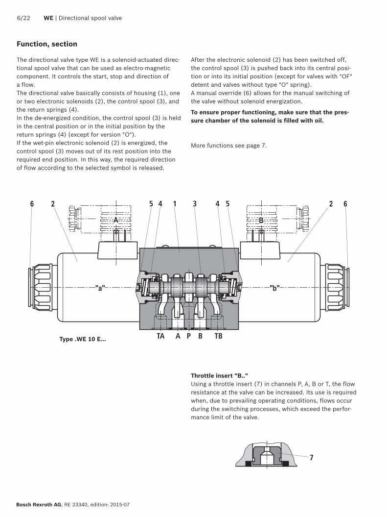
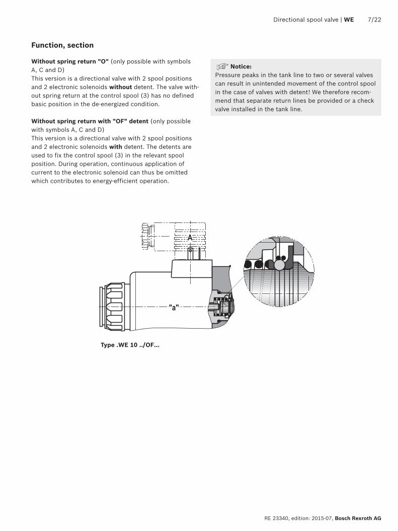
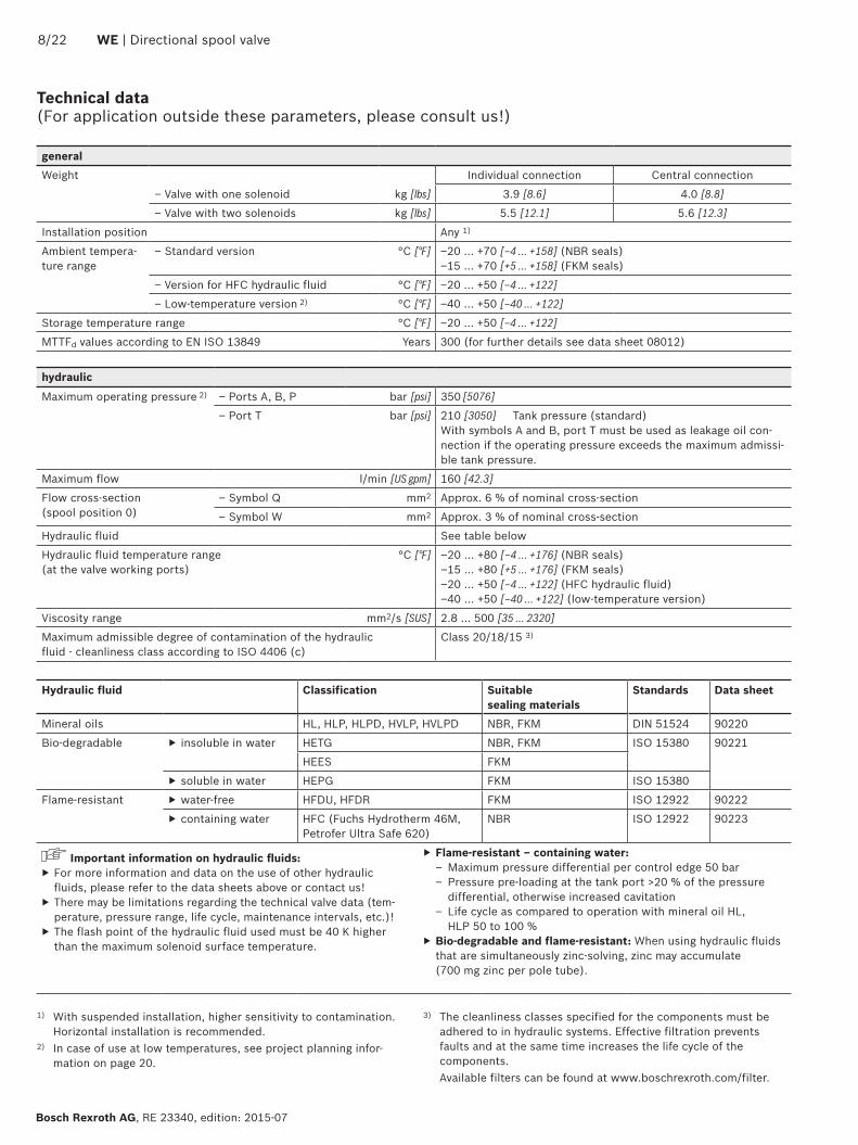
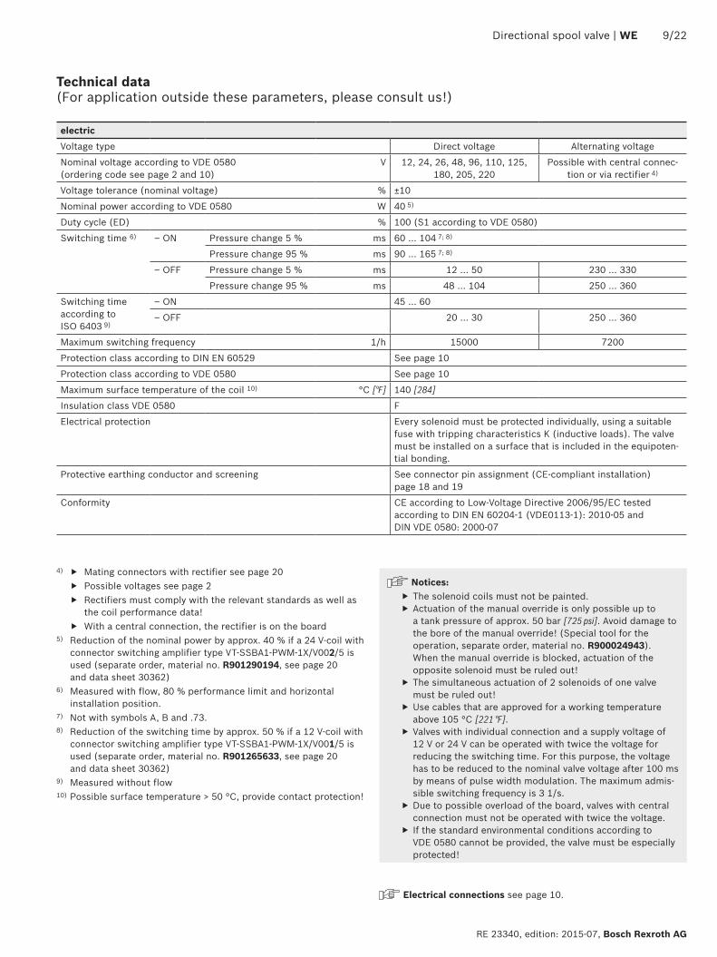
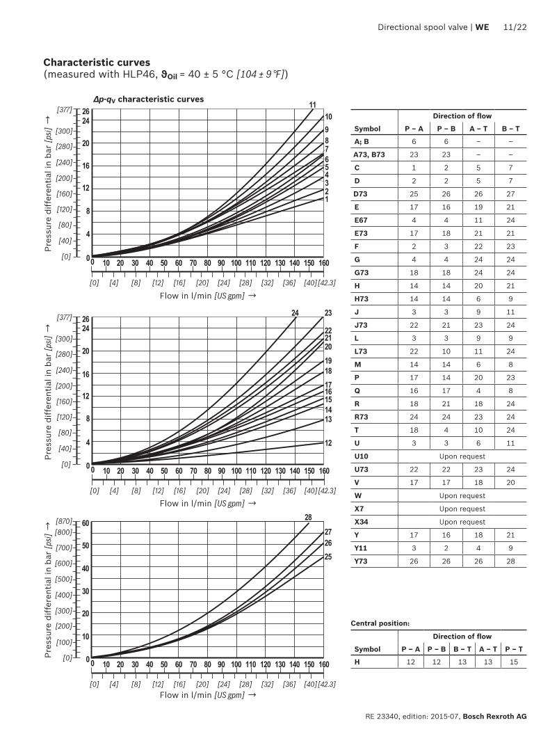
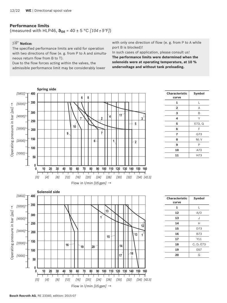
200
300
100
50
0 10 20 30 40 50 60
[0] [4] [8] [12]
[1000]
[2000]
[3000]
[4000]
150
250
350
70 80 90 100 110 120
[16] [20] [24] [28]
[5000]
400
130 140 150 160
[30] [32] [34]
[5802]
[423]
0
16
15
1817
12
13
14
13
1
1
19 20
1222 WE | Directional spool valve
Bosch Rexroth AG RE 23340 edition 2015-07
Performance limits (measured with HLP46 ϑOil = 40 plusmn 5 degC [104 plusmn 9 degF])
NoticeThe specified performance limits are valid for operation with two directions of flow (e g from P to A and simulta-neous return flow from B to T)Due to the flow forces acting within the valves the admissible performance limit may be considerably lower
with only one direction of flow (e g from P to A while port B is blocked)In such cases of application please consult usThe performance limits were determined when the solenoids were at operating temperature at 10 undervoltage and without tank preloading
Ope
ratin
g pr
essu
re in
bar
[psi]
rarrO
pera
ting
pres
sure
in b
ar [p
si] rarr
Flow in lmin [US gpm] rarr
Flow in lmin [US gpm] rarr
Characteristic curve
Symbol
1 L
2 A
3 B
4 Y
5 E73 Q
6 F
7 G73
8 M V
9 P
10 A73
11 H73
Characteristic curve
Symbol
1 L
12 AO
13 J
14 H
15 D73
16 B73
17 Y11
18 C D E73
19 E67
20 G
Spring side
Solenoid side
200
300
100
50
0 10 20 30 40 50 60
[0] [4] [8] [12]
[1000]
[2000]
[3000]
[4000]
150
250
350
70 80 90 100 110 120
[16] [20] [24] [28]
[5000]
400
130 140 150 160
[30] [32] [34]
[5802]
[423]
0
23
22
21
25
24
24
27
27
26
21
200
300
100
50
0 10 20 30 40 50 60
[0] [4] [8] [12]
[1000]
[2000]
[3000]
[4000]
150
250
350
70 80 90 100 110 120
[16] [20] [24] [28]
[5000]
400
130 140 150 160
[30] [32] [34]
[5802]
[423]
0
28
31
32
3435
29
30
31
2833
Directional spool valve | WE 1322
RE 23340 edition 2015-07 Bosch Rexroth AG
Performance limits (measured with HLP46 ϑOil = 40 plusmn 5 degC [104 plusmn 9 degF])
NoticeThe specified performance limits are valid for operation with two directions of flow (e g from P to A and simulta-neous return flow from B to T)Due to the flow forces acting within the valves the admissible performance limit may be considerably lower
with only one direction of flow (e g from P to A while port B is blocked)In such cases of application please consult usThe performance limits were determined when the solenoids were at operating temperature at 10 undervoltage and without tank preloading
Ope
ratin
g pr
essu
re in
bar
[psi]
rarrO
pera
ting
pres
sure
in b
ar [p
si] rarr
Flow in lmin [US gpm] rarr
Flow in lmin [US gpm] rarr
Characteristic curve
Symbol
21 A B
22 G73
23 F L73
24 E
25 CO DO
26 J73
27 U
Characteristic curve
Symbol
28 Q
29 V
30 P
31 R
32 R73
33 T
34 U73
35 Y73
Solenoid side
Solenoid side
001100[0000440]
Rzmax 4
Oslash11 Oslash66
TA TBA B
PF1 F2
1511
42
1512
0
191922
4012
802675
30
13 13
10
11 12
51 52 69
161514
12
F3F4
[05
9][4
50
]
[15
7]
[102] [315]
[11
8]
[47
2][0
59]
[295]
70[0
47]
[27
6]
[075]
[363]
51 52
14
[Oslash043] [Oslash026]
80[3
15]
A B
53
15
55
15[0
59]
54
12
[05
9]
12
Oslash150
[Oslash5
91]
126
[49
6]
12
120
[47
2]
20[0
79]
75[295]
111 112
1422 WE | Directional spool valve
Bosch Rexroth AG RE 23340 edition 2015-07
Dimensions Individual connection (dimensions in mm [inch])
Required surface quality of the valve contact surface
Notices Deviating from ISO 4401 port T is called TA and port T1 is called TB in this data sheet
The dimensions are nominal dimensions which are subject to tolerances
Dimensions for manual overrides see page 16Item explanations valve mounting screws and subplates see page 17
13
001100[0000440]
Rzmax 4
Directional spool valve | WE 1522
RE 23340 edition 2015-07 Bosch Rexroth AG
Dimensions Central connection (dimensions in mm [inch])
Required surface quality of the valve contact surface
NoticeThe dimensions are nominal dimensions which are subject to tolerances
Special points with version DAL and DL Version DL is only suitable for permanently
installed cables Lines must be routed in a pull-relieved manner
Minimum line cross-section 075 mm2 (AWG 18) With a maximum line cross-section of 150 mm2
(AWG 16) and if wire end ferrules are used wire end ferrules without flange must be crimped to a maximum cross-section of 15 mm x 2 mm (trapezoi-dal crimp) using an appropriate tool (e g PZ 65 co Weidmuumlller) to ensure that they fit into the printed circuit board terminals
Before crimping the wires have to be stripped to 9-1 mm [035ndash0039 inch]
For the corresponding line cross-section 1) wire end ferrules without flange (according to DIN 46228-1) with a length of 8 mm [031 inch] are to be used
For the earthing connection ring cable lugs accord-ing to DIN 46234-4-1 are to be used tightening torque MA = 175 Nm [129 ft-lbs] plusmn10
Dimensions for manual overrides see page 16Item explanations valve mounting screws and subplates see page 17
1) 075 mm2 (AWG 20) 100 mm2 (AWG 18) 150 mm2 (AWG 16)
NoticeThe lines must be finely stranded
001100[0000440]
Rzmax 4
1622 WE | Directional spool valve
Bosch Rexroth AG RE 23340 edition 2015-07
Dimensions Manual overrides (dimensions in mm [inch])
Required surface quality of the valve contact surface
Item explanations valve mounting screws and subplates see page 17
NoticeThe dimensions are nominal dimensions which are subject to tolerances
2 Version without and with concealed manual override N9 (standard)
3 Version with concealed manual override and protective cap N8 (The protective cap must be removed prior to actuation)
4 Version with manual override N5 and N6
Directional spool valve | WE 1722
RE 23340 edition 2015-07 Bosch Rexroth AG
Dimensions
Subplates according to data sheet 45054 (separate order) G 6601 (G38) G 6701 (G12) G 53401 (G34)G 6612 (SAE-6 916-18) 1) G 6712 (SAE-8 34-16) 1) G 53412 (SAE-12 1-116-12) 1)
1) Upon request
Valve mounting screws (separate order)4 metric hexagon socket head cap screws ISO 4762 - M6 x 40 - 109-flZn-240h-L (friction coefficient micrototal = 009 to 014) tightening torque MA = 125 Nm [92 ft-lbs] plusmn10 material no R913000058 or 4 hexagon socket head cap screws ISO 4762 - M6 x 40 - 109 (self procurement) (friction coefficient micrototal = 012 to 017) tightening torque MA = 155 Nm [114 ft-lbs] plusmn10
4 UNC hexagon socket head cap screws 14-20 UNC x 1-12 ASTM-A574 (friction coefficient) micrototal = 019 to 024) tightening torque MA = 25 Nm [184 ft-lbs] plusmn15 (friction coefficient micrototal = 012 to 017) tightening torque MA = 19 Nm [140 ft-lbs] plusmn10 material no R978800710
With different friction coefficients the tightening torques are to be adjusted accordingly
11 Solenoid a12 Solenoid b
2 Version without and with concealed manual override N9 (standard)
3 Version with concealed manual override and protective cap N8 (The protective cap must be removed prior to actuation)
4 Version with manual override N5 and N651 Mating connector without circuitry for connector K4
(separate order see page 20 and data sheet 08006)52 Mating connector without circuitry for connector K4K
(separate order see data sheet 08006)53 Mating connector angled with M12x1 plug-in connection and
status LED for connector K72L (separate order see data sheet 08006)
54 Double mating connector withoutwith circuitry for connec-tor K4 (separate order see data sheet 08006)
55 Mating connector (AMP Junior Timer) for connector C4Z (separate order see data sheet 08006)
6 Mating connector with circuitry for connector K4 (separate order see page 20 and data sheet 08006)
71 Cable gland Pg 16 DL (terminal area 6 hellip 12 mm [024 hellip 047 inch]) lock nut tightening torque MA = 33 Nm [243 ft-lbs] plusmn10
72 Central connection box DAL 12 NPT tightening torque MA = 5 Nm [369 ft-lbs] plusmn10 sealing by sealant
73 Connector DK6L and DK25L81 Mating connector for connector DK6L (separate order
material no R900002803 see data sheet 08006)82 Mini-change connector 5-pole for connector DK25L
(separate order material no R900057631)9 Name plate
10 Identical seal rings for ports A B P TA TB111 Plug screw for valves with one solenoid on B side112 Plug screw for valves with one solenoid on A side
12 Space required to remove the mating connectorangled socket
13 Space required to remove the coil14 Mounting nut tightening torque MA = 145plusmn15 Nm
[1069plusmn11 ft-lbs]15 Porting pattern according to ISO 4401-05-04-0-05 and
NFPA T351 R2-2002 D05
16 Connection TB can only be used in connection with sepa-rately produced bore
17 CoverNotice The valve may only be operated with properly mounted cover Tightening torque of the cover screws MA = 10 Nm [074 ft-lbs] plusmn10 Prior to opening the frame it must be ensured that the valve has no voltage
1822 WE | Directional spool valve
Bosch Rexroth AG RE 23340 edition 2015-07
Over-current fuse and switch-off voltage peaks
Maximum admissible overvoltages according to DIN EN 60664-12008-01 (VDE 0110-1) (overvoltage category II)
Electrical connection 1)Nominal voltage
in VRated current
in AMaximum admissible switch-off
overvoltage in V 2)
K4 K4K DAL D6KL DL 12 372 500K4 K4K K72L DAL D6KL DL DJL DK25L 24 174 500K4 C4Z 26 170 500K4 48 057 500K4 DAL D6KL DL DK25L 96 047 500D6KL DL DJL 110 041 500K4 125 022 500K4 C4Z 180 028 500K4 DAL D6KL DL 205 022 500K4 DAL D6KL DL 220 021 500
NoticeWhen solenoid coils are switched off voltage peaks result which may cause faults or damage in the connected control electronics We therefore recommend limiting them to 2 x nominal voltage by means of an interference protection circuit It must be noted that a diode switched in an antiparallel form extends the switching off time
Electrical connections assignment ndash individual connection
1) Interference protection circuit integrated2) To be ensured by user circuitry
Electrical connections and coil connection combinations
Connector ordering codes Top view Circuit diagram PinConnections assignment
Connector 3-pole (2+PE) according to DIN EN 175301-803 (IP65)
K4K4K 3)
4)
1
2
1 Solenoid coil polarity-independent2Earthing
Connector 4-pole according to IEC 60947-5-2 M12x1 with suppres-sor diode only 24 V DC integrated interference protection circuit and status LED
K72L
1
2 3
4
+
ndash5
1 Internal bridge23 Solenoid coil GND4 Solenoid coil 24 V DC
supply voltage5 without function
2-pole connector type AMP Junior-Timer rotated by 90deg relative to valve axis
C4Z
1
2
1 Solenoid coil polarity-independent
2
3) Coil with potted-in connector base and sealing element to valve housing (IP67)
4) M3 tightening torque maximum MA max = 05 Nm [037 ft-lbs]
Directional spool valve | WE 1922
RE 23340 edition 2015-07 Bosch Rexroth AG
Electrical connections assignment ndash central connection
Electrical connections and coil connection combinations
Connector ordering codes Top view Circuit diagram PinConnections assignment
Cable gland at the cover with indicator light (terminal area 6 hellip 12 mm [023 hellip 047 inch])
DL
1+2ndash
ldquobrdquo
ldquoardquo
3+4ndash
Dire
ct v
olta
ge
ldquoardquo ldquobrdquo
1+ 3+
2ndash 4ndash2) 1+
Valve solenoid a 1)
2ndash
3+
Valve solenoid b 1)
4ndash
Earthing
Cable gland at the cover with indicator light and cable bridge at the ground connection(terminal area 6 hellip 12 mm [023 hellip 047 inch])
DJL
Alte
rnat
ing
volta
ge
ndash
+
Without mating connector threaded connection 12-14 NPT(terminal area 6 hellip 12 mm [023 hellip 047 inch])
DAL 3)
Central plug-in connection at the cover with indicator light (without mating connector) with connector according to DIN EN 175201-804
DK6L
1+
654ndash3+
2ndashPE
ldquobrdquo
ldquoardquo
1 Valve solenoid a2
3 Valve solenoid b4
5Not used
6
Earthing
Mini-change connector 5-pole according to ANSIB9355M-1981
DK25L
ldquobrdquo
ldquoardquo
1+5ndash
4ndash 2+3
1 Valve solenoid a5
2 Valve solenoid b4
3 Earthing
1) Core marking + rarr red ndash rarr blue
2) Bridge only for version DJL3) Cable gland with NPT thread
NPT
12ldquo
2022 WE | Directional spool valve
Bosch Rexroth AG RE 23340 edition 2015-07
Project planning information
Temperature range and maximum operating pressure in case of use at low temperaturesPort Pressure Temperature range in degC [degF]ndash P A B T Static 100 bar [1450 psi] ndash40 hellip ndash35 [ndash40 hellip ndash31]ndash P A B Dynamic from 100 bar [1450 psi] to 350 bar [5076 psi] in linear form as a
function of the temperaturendash35 hellip ndash30 [ndash31 hellip ndash22]
ndash T Dynamic from 100 bar [1450 psi] to 210 bar [3050 psi] in linear form as a function of the temperature
ndash35 hellip ndash30 [ndash31 hellip ndash22]
ndash P A B T Maximum operating pressure ndash30 hellip +50 [ndash22 hellip 122]
Cartridge with PWM connector according to data sheet 30362
Depending on the control spool increasing the perfor-mance limit is possible
With version G24 (energy saving) the coil tempera-ture is reduced by ge 30 degC for 100 duty cycle
Mating connectors according to DIN EN 175301-803
Energy savings and fast switching 1)
Details see data sheet 30362Material number
Type VT-SSBA1-PWM-1XV0015 as fast switching amplifier
(switching time reduction by approx 50 ) 2)
Type VT-SSBA1-PWM-1XV0025 for energy reduction
(energy savings of approx 40 ) 3)
ab Black R901265633 R901290194
For details and more mating connectors see data sheet 08006
Port Valv
e si
de
Color
Material no
Without circuitryWith indicator light
12 240 VWith rectifier 12 240 V
With indicator light and Zener diode suppression circuit
24 V
M16 x 15a Gray R901017010 ndash ndash ndash
ab Black R901017011 R901017022 R901017025 R901017026
12 NPT (Pg16)
a Redbrown R900004823 ndash ndash ndash
ab Black R900011039 R900057453 R900842566 ndash
1) Only with symbols C D E E67 J J2 Y and Y11 not for version D with reinforced compression spring
2) Only available for G12 and K4K4K version3) Only available for G24 and K4K4K version
Directional spool valve | WE 2122
RE 23340 edition 2015-07 Bosch Rexroth AG
Additional information
Subplates Data sheet 45054 Hydraulic fluids on mineral oil basis Data sheet 90220 Environmentally compatible hydraulic fluids Data sheet 90221 Flame-resistant water-free hydraulic fluids Data sheet 90222 Connector switching amplifier type VT-SSBA1 Data sheet 30362 Directional spool and seat valves with electrical actuation and M12x1 plug-in
connectionData sheet 08010
Reliability characteristics according to EN ISO 13849 Data sheet 08012 Hydraulic valves for industrial applications Data sheet 07600-B CE declaration of conformity according to Low-voltage Directive 200695EC Upon request Selection of filters wwwboschrexrothcomfilter Information on available spare parts wwwboschrexrothcomspc
Bosch Rexroth AG RE 23340 edition 2015-07
2222 WE | Directional spool valve
Bosch Rexroth AG HydraulicsZum Eisengieszliger 197816 Lohr am Main Germany Phone +49 (0) 93 52thinspthinsp18-0 documentationboschrexrothde wwwboschrexrothde
copy This document as well as the data specifications and other information set forth in it are the exclusive property of Bosch Rexroth AG It may not be reproduced or given to third parties without its consentThe data specified above only serve to describe the product No statements concerning a certain condition or suitability for a certain application can be derived from our information The information given does not release the user from the obligation of own judgment and verification It must be remembered that our products are subject to a natural process of wear and aging
Notes
Bosch Rexroth AG HydraulicsZum Eisengieszliger 197816 Lohr am Main Germany Phone +49 (0) 93 52thinspthinsp18-0 documentationboschrexrothde wwwboschrexrothde
copy This document as well as the data specifications and other information set forth in it are the exclusive property of Bosch Rexroth AG It may not be reproduced or given to third parties without its consentThe data specified above only serve to describe the product No statements concerning a certain condition or suitability for a certain application can be derived from our information The information given does not release the user from the obligation of own judgment and verification It must be remembered that our products are subject to a natural process of wear and aging
Directional spool valve | WE 2322
RE 23340 edition 2015-07 Bosch Rexroth AG
Notes
Bosch Rexroth AG RE 23340 edition 2015-07
2422 WE | Directional spool valve
Notes
- Features
- Contents
- Ordering codes
- Symbols
- Function section
- Technical data
- Characteristic curves
- Performance limits
- Dimensions
- Over-current fuse and switch-off voltage peaks
- Electrical connections assignment ndash individual connection
- Mating connectors
- Project planning information
- Additional information
-
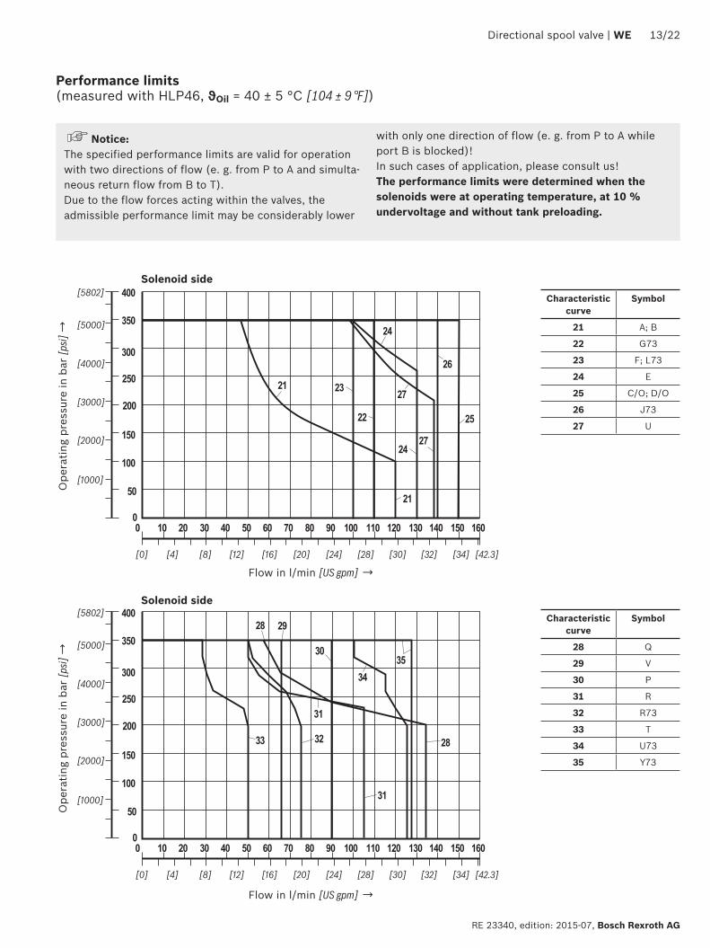
200
300
100
50
0 10 20 30 40 50 60
[0] [4] [8] [12]
[1000]
[2000]
[3000]
[4000]
150
250
350
70 80 90 100 110 120
[16] [20] [24] [28]
[5000]
400
130 140 150 160
[30] [32] [34]
[5802]
[423]
0
23
22
21
25
24
24
27
27
26
21
200
300
100
50
0 10 20 30 40 50 60
[0] [4] [8] [12]
[1000]
[2000]
[3000]
[4000]
150
250
350
70 80 90 100 110 120
[16] [20] [24] [28]
[5000]
400
130 140 150 160
[30] [32] [34]
[5802]
[423]
0
28
31
32
3435
29
30
31
2833
Directional spool valve | WE 1322
RE 23340 edition 2015-07 Bosch Rexroth AG
Performance limits (measured with HLP46 ϑOil = 40 plusmn 5 degC [104 plusmn 9 degF])
NoticeThe specified performance limits are valid for operation with two directions of flow (e g from P to A and simulta-neous return flow from B to T)Due to the flow forces acting within the valves the admissible performance limit may be considerably lower
with only one direction of flow (e g from P to A while port B is blocked)In such cases of application please consult usThe performance limits were determined when the solenoids were at operating temperature at 10 undervoltage and without tank preloading
Ope
ratin
g pr
essu
re in
bar
[psi]
rarrO
pera
ting
pres
sure
in b
ar [p
si] rarr
Flow in lmin [US gpm] rarr
Flow in lmin [US gpm] rarr
Characteristic curve
Symbol
21 A B
22 G73
23 F L73
24 E
25 CO DO
26 J73
27 U
Characteristic curve
Symbol
28 Q
29 V
30 P
31 R
32 R73
33 T
34 U73
35 Y73
Solenoid side
Solenoid side
001100[0000440]
Rzmax 4
Oslash11 Oslash66
TA TBA B
PF1 F2
1511
42
1512
0
191922
4012
802675
30
13 13
10
11 12
51 52 69
161514
12
F3F4
[05
9][4
50
]
[15
7]
[102] [315]
[11
8]
[47
2][0
59]
[295]
70[0
47]
[27
6]
[075]
[363]
51 52
14
[Oslash043] [Oslash026]
80[3
15]
A B
53
15
55
15[0
59]
54
12
[05
9]
12
Oslash150
[Oslash5
91]
126
[49
6]
12
120
[47
2]
20[0
79]
75[295]
111 112
1422 WE | Directional spool valve
Bosch Rexroth AG RE 23340 edition 2015-07
Dimensions Individual connection (dimensions in mm [inch])
Required surface quality of the valve contact surface
Notices Deviating from ISO 4401 port T is called TA and port T1 is called TB in this data sheet
The dimensions are nominal dimensions which are subject to tolerances
Dimensions for manual overrides see page 16Item explanations valve mounting screws and subplates see page 17
13
001100[0000440]
Rzmax 4
Directional spool valve | WE 1522
RE 23340 edition 2015-07 Bosch Rexroth AG
Dimensions Central connection (dimensions in mm [inch])
Required surface quality of the valve contact surface
NoticeThe dimensions are nominal dimensions which are subject to tolerances
Special points with version DAL and DL Version DL is only suitable for permanently
installed cables Lines must be routed in a pull-relieved manner
Minimum line cross-section 075 mm2 (AWG 18) With a maximum line cross-section of 150 mm2
(AWG 16) and if wire end ferrules are used wire end ferrules without flange must be crimped to a maximum cross-section of 15 mm x 2 mm (trapezoi-dal crimp) using an appropriate tool (e g PZ 65 co Weidmuumlller) to ensure that they fit into the printed circuit board terminals
Before crimping the wires have to be stripped to 9-1 mm [035ndash0039 inch]
For the corresponding line cross-section 1) wire end ferrules without flange (according to DIN 46228-1) with a length of 8 mm [031 inch] are to be used
For the earthing connection ring cable lugs accord-ing to DIN 46234-4-1 are to be used tightening torque MA = 175 Nm [129 ft-lbs] plusmn10
Dimensions for manual overrides see page 16Item explanations valve mounting screws and subplates see page 17
1) 075 mm2 (AWG 20) 100 mm2 (AWG 18) 150 mm2 (AWG 16)
NoticeThe lines must be finely stranded
001100[0000440]
Rzmax 4
1622 WE | Directional spool valve
Bosch Rexroth AG RE 23340 edition 2015-07
Dimensions Manual overrides (dimensions in mm [inch])
Required surface quality of the valve contact surface
Item explanations valve mounting screws and subplates see page 17
NoticeThe dimensions are nominal dimensions which are subject to tolerances
2 Version without and with concealed manual override N9 (standard)
3 Version with concealed manual override and protective cap N8 (The protective cap must be removed prior to actuation)
4 Version with manual override N5 and N6
Directional spool valve | WE 1722
RE 23340 edition 2015-07 Bosch Rexroth AG
Dimensions
Subplates according to data sheet 45054 (separate order) G 6601 (G38) G 6701 (G12) G 53401 (G34)G 6612 (SAE-6 916-18) 1) G 6712 (SAE-8 34-16) 1) G 53412 (SAE-12 1-116-12) 1)
1) Upon request
Valve mounting screws (separate order)4 metric hexagon socket head cap screws ISO 4762 - M6 x 40 - 109-flZn-240h-L (friction coefficient micrototal = 009 to 014) tightening torque MA = 125 Nm [92 ft-lbs] plusmn10 material no R913000058 or 4 hexagon socket head cap screws ISO 4762 - M6 x 40 - 109 (self procurement) (friction coefficient micrototal = 012 to 017) tightening torque MA = 155 Nm [114 ft-lbs] plusmn10
4 UNC hexagon socket head cap screws 14-20 UNC x 1-12 ASTM-A574 (friction coefficient) micrototal = 019 to 024) tightening torque MA = 25 Nm [184 ft-lbs] plusmn15 (friction coefficient micrototal = 012 to 017) tightening torque MA = 19 Nm [140 ft-lbs] plusmn10 material no R978800710
With different friction coefficients the tightening torques are to be adjusted accordingly
11 Solenoid a12 Solenoid b
2 Version without and with concealed manual override N9 (standard)
3 Version with concealed manual override and protective cap N8 (The protective cap must be removed prior to actuation)
4 Version with manual override N5 and N651 Mating connector without circuitry for connector K4
(separate order see page 20 and data sheet 08006)52 Mating connector without circuitry for connector K4K
(separate order see data sheet 08006)53 Mating connector angled with M12x1 plug-in connection and
status LED for connector K72L (separate order see data sheet 08006)
54 Double mating connector withoutwith circuitry for connec-tor K4 (separate order see data sheet 08006)
55 Mating connector (AMP Junior Timer) for connector C4Z (separate order see data sheet 08006)
6 Mating connector with circuitry for connector K4 (separate order see page 20 and data sheet 08006)
71 Cable gland Pg 16 DL (terminal area 6 hellip 12 mm [024 hellip 047 inch]) lock nut tightening torque MA = 33 Nm [243 ft-lbs] plusmn10
72 Central connection box DAL 12 NPT tightening torque MA = 5 Nm [369 ft-lbs] plusmn10 sealing by sealant
73 Connector DK6L and DK25L81 Mating connector for connector DK6L (separate order
material no R900002803 see data sheet 08006)82 Mini-change connector 5-pole for connector DK25L
(separate order material no R900057631)9 Name plate
10 Identical seal rings for ports A B P TA TB111 Plug screw for valves with one solenoid on B side112 Plug screw for valves with one solenoid on A side
12 Space required to remove the mating connectorangled socket
13 Space required to remove the coil14 Mounting nut tightening torque MA = 145plusmn15 Nm
[1069plusmn11 ft-lbs]15 Porting pattern according to ISO 4401-05-04-0-05 and
NFPA T351 R2-2002 D05
16 Connection TB can only be used in connection with sepa-rately produced bore
17 CoverNotice The valve may only be operated with properly mounted cover Tightening torque of the cover screws MA = 10 Nm [074 ft-lbs] plusmn10 Prior to opening the frame it must be ensured that the valve has no voltage
1822 WE | Directional spool valve
Bosch Rexroth AG RE 23340 edition 2015-07
Over-current fuse and switch-off voltage peaks
Maximum admissible overvoltages according to DIN EN 60664-12008-01 (VDE 0110-1) (overvoltage category II)
Electrical connection 1)Nominal voltage
in VRated current
in AMaximum admissible switch-off
overvoltage in V 2)
K4 K4K DAL D6KL DL 12 372 500K4 K4K K72L DAL D6KL DL DJL DK25L 24 174 500K4 C4Z 26 170 500K4 48 057 500K4 DAL D6KL DL DK25L 96 047 500D6KL DL DJL 110 041 500K4 125 022 500K4 C4Z 180 028 500K4 DAL D6KL DL 205 022 500K4 DAL D6KL DL 220 021 500
NoticeWhen solenoid coils are switched off voltage peaks result which may cause faults or damage in the connected control electronics We therefore recommend limiting them to 2 x nominal voltage by means of an interference protection circuit It must be noted that a diode switched in an antiparallel form extends the switching off time
Electrical connections assignment ndash individual connection
1) Interference protection circuit integrated2) To be ensured by user circuitry
Electrical connections and coil connection combinations
Connector ordering codes Top view Circuit diagram PinConnections assignment
Connector 3-pole (2+PE) according to DIN EN 175301-803 (IP65)
K4K4K 3)
4)
1
2
1 Solenoid coil polarity-independent2Earthing
Connector 4-pole according to IEC 60947-5-2 M12x1 with suppres-sor diode only 24 V DC integrated interference protection circuit and status LED
K72L
1
2 3
4
+
ndash5
1 Internal bridge23 Solenoid coil GND4 Solenoid coil 24 V DC
supply voltage5 without function
2-pole connector type AMP Junior-Timer rotated by 90deg relative to valve axis
C4Z
1
2
1 Solenoid coil polarity-independent
2
3) Coil with potted-in connector base and sealing element to valve housing (IP67)
4) M3 tightening torque maximum MA max = 05 Nm [037 ft-lbs]
Directional spool valve | WE 1922
RE 23340 edition 2015-07 Bosch Rexroth AG
Electrical connections assignment ndash central connection
Electrical connections and coil connection combinations
Connector ordering codes Top view Circuit diagram PinConnections assignment
Cable gland at the cover with indicator light (terminal area 6 hellip 12 mm [023 hellip 047 inch])
DL
1+2ndash
ldquobrdquo
ldquoardquo
3+4ndash
Dire
ct v
olta
ge
ldquoardquo ldquobrdquo
1+ 3+
2ndash 4ndash2) 1+
Valve solenoid a 1)
2ndash
3+
Valve solenoid b 1)
4ndash
Earthing
Cable gland at the cover with indicator light and cable bridge at the ground connection(terminal area 6 hellip 12 mm [023 hellip 047 inch])
DJL
Alte
rnat
ing
volta
ge
ndash
+
Without mating connector threaded connection 12-14 NPT(terminal area 6 hellip 12 mm [023 hellip 047 inch])
DAL 3)
Central plug-in connection at the cover with indicator light (without mating connector) with connector according to DIN EN 175201-804
DK6L
1+
654ndash3+
2ndashPE
ldquobrdquo
ldquoardquo
1 Valve solenoid a2
3 Valve solenoid b4
5Not used
6
Earthing
Mini-change connector 5-pole according to ANSIB9355M-1981
DK25L
ldquobrdquo
ldquoardquo
1+5ndash
4ndash 2+3
1 Valve solenoid a5
2 Valve solenoid b4
3 Earthing
1) Core marking + rarr red ndash rarr blue
2) Bridge only for version DJL3) Cable gland with NPT thread
NPT
12ldquo
2022 WE | Directional spool valve
Bosch Rexroth AG RE 23340 edition 2015-07
Project planning information
Temperature range and maximum operating pressure in case of use at low temperaturesPort Pressure Temperature range in degC [degF]ndash P A B T Static 100 bar [1450 psi] ndash40 hellip ndash35 [ndash40 hellip ndash31]ndash P A B Dynamic from 100 bar [1450 psi] to 350 bar [5076 psi] in linear form as a
function of the temperaturendash35 hellip ndash30 [ndash31 hellip ndash22]
ndash T Dynamic from 100 bar [1450 psi] to 210 bar [3050 psi] in linear form as a function of the temperature
ndash35 hellip ndash30 [ndash31 hellip ndash22]
ndash P A B T Maximum operating pressure ndash30 hellip +50 [ndash22 hellip 122]
Cartridge with PWM connector according to data sheet 30362
Depending on the control spool increasing the perfor-mance limit is possible
With version G24 (energy saving) the coil tempera-ture is reduced by ge 30 degC for 100 duty cycle
Mating connectors according to DIN EN 175301-803
Energy savings and fast switching 1)
Details see data sheet 30362Material number
Type VT-SSBA1-PWM-1XV0015 as fast switching amplifier
(switching time reduction by approx 50 ) 2)
Type VT-SSBA1-PWM-1XV0025 for energy reduction
(energy savings of approx 40 ) 3)
ab Black R901265633 R901290194
For details and more mating connectors see data sheet 08006
Port Valv
e si
de
Color
Material no
Without circuitryWith indicator light
12 240 VWith rectifier 12 240 V
With indicator light and Zener diode suppression circuit
24 V
M16 x 15a Gray R901017010 ndash ndash ndash
ab Black R901017011 R901017022 R901017025 R901017026
12 NPT (Pg16)
a Redbrown R900004823 ndash ndash ndash
ab Black R900011039 R900057453 R900842566 ndash
1) Only with symbols C D E E67 J J2 Y and Y11 not for version D with reinforced compression spring
2) Only available for G12 and K4K4K version3) Only available for G24 and K4K4K version
Directional spool valve | WE 2122
RE 23340 edition 2015-07 Bosch Rexroth AG
Additional information
Subplates Data sheet 45054 Hydraulic fluids on mineral oil basis Data sheet 90220 Environmentally compatible hydraulic fluids Data sheet 90221 Flame-resistant water-free hydraulic fluids Data sheet 90222 Connector switching amplifier type VT-SSBA1 Data sheet 30362 Directional spool and seat valves with electrical actuation and M12x1 plug-in
connectionData sheet 08010
Reliability characteristics according to EN ISO 13849 Data sheet 08012 Hydraulic valves for industrial applications Data sheet 07600-B CE declaration of conformity according to Low-voltage Directive 200695EC Upon request Selection of filters wwwboschrexrothcomfilter Information on available spare parts wwwboschrexrothcomspc
Bosch Rexroth AG RE 23340 edition 2015-07
2222 WE | Directional spool valve
Bosch Rexroth AG HydraulicsZum Eisengieszliger 197816 Lohr am Main Germany Phone +49 (0) 93 52thinspthinsp18-0 documentationboschrexrothde wwwboschrexrothde
copy This document as well as the data specifications and other information set forth in it are the exclusive property of Bosch Rexroth AG It may not be reproduced or given to third parties without its consentThe data specified above only serve to describe the product No statements concerning a certain condition or suitability for a certain application can be derived from our information The information given does not release the user from the obligation of own judgment and verification It must be remembered that our products are subject to a natural process of wear and aging
Notes
Bosch Rexroth AG HydraulicsZum Eisengieszliger 197816 Lohr am Main Germany Phone +49 (0) 93 52thinspthinsp18-0 documentationboschrexrothde wwwboschrexrothde
copy This document as well as the data specifications and other information set forth in it are the exclusive property of Bosch Rexroth AG It may not be reproduced or given to third parties without its consentThe data specified above only serve to describe the product No statements concerning a certain condition or suitability for a certain application can be derived from our information The information given does not release the user from the obligation of own judgment and verification It must be remembered that our products are subject to a natural process of wear and aging
Directional spool valve | WE 2322
RE 23340 edition 2015-07 Bosch Rexroth AG
Notes
Bosch Rexroth AG RE 23340 edition 2015-07
2422 WE | Directional spool valve
Notes
- Features
- Contents
- Ordering codes
- Symbols
- Function section
- Technical data
- Characteristic curves
- Performance limits
- Dimensions
- Over-current fuse and switch-off voltage peaks
- Electrical connections assignment ndash individual connection
- Mating connectors
- Project planning information
- Additional information
-

001100[0000440]
Rzmax 4
Oslash11 Oslash66
TA TBA B
PF1 F2
1511
42
1512
0
191922
4012
802675
30
13 13
10
11 12
51 52 69
161514
12
F3F4
[05
9][4
50
]
[15
7]
[102] [315]
[11
8]
[47
2][0
59]
[295]
70[0
47]
[27
6]
[075]
[363]
51 52
14
[Oslash043] [Oslash026]
80[3
15]
A B
53
15
55
15[0
59]
54
12
[05
9]
12
Oslash150
[Oslash5
91]
126
[49
6]
12
120
[47
2]
20[0
79]
75[295]
111 112
1422 WE | Directional spool valve
Bosch Rexroth AG RE 23340 edition 2015-07
Dimensions Individual connection (dimensions in mm [inch])
Required surface quality of the valve contact surface
Notices Deviating from ISO 4401 port T is called TA and port T1 is called TB in this data sheet
The dimensions are nominal dimensions which are subject to tolerances
Dimensions for manual overrides see page 16Item explanations valve mounting screws and subplates see page 17
13
001100[0000440]
Rzmax 4
Directional spool valve | WE 1522
RE 23340 edition 2015-07 Bosch Rexroth AG
Dimensions Central connection (dimensions in mm [inch])
Required surface quality of the valve contact surface
NoticeThe dimensions are nominal dimensions which are subject to tolerances
Special points with version DAL and DL Version DL is only suitable for permanently
installed cables Lines must be routed in a pull-relieved manner
Minimum line cross-section 075 mm2 (AWG 18) With a maximum line cross-section of 150 mm2
(AWG 16) and if wire end ferrules are used wire end ferrules without flange must be crimped to a maximum cross-section of 15 mm x 2 mm (trapezoi-dal crimp) using an appropriate tool (e g PZ 65 co Weidmuumlller) to ensure that they fit into the printed circuit board terminals
Before crimping the wires have to be stripped to 9-1 mm [035ndash0039 inch]
For the corresponding line cross-section 1) wire end ferrules without flange (according to DIN 46228-1) with a length of 8 mm [031 inch] are to be used
For the earthing connection ring cable lugs accord-ing to DIN 46234-4-1 are to be used tightening torque MA = 175 Nm [129 ft-lbs] plusmn10
Dimensions for manual overrides see page 16Item explanations valve mounting screws and subplates see page 17
1) 075 mm2 (AWG 20) 100 mm2 (AWG 18) 150 mm2 (AWG 16)
NoticeThe lines must be finely stranded
001100[0000440]
Rzmax 4
1622 WE | Directional spool valve
Bosch Rexroth AG RE 23340 edition 2015-07
Dimensions Manual overrides (dimensions in mm [inch])
Required surface quality of the valve contact surface
Item explanations valve mounting screws and subplates see page 17
NoticeThe dimensions are nominal dimensions which are subject to tolerances
2 Version without and with concealed manual override N9 (standard)
3 Version with concealed manual override and protective cap N8 (The protective cap must be removed prior to actuation)
4 Version with manual override N5 and N6
Directional spool valve | WE 1722
RE 23340 edition 2015-07 Bosch Rexroth AG
Dimensions
Subplates according to data sheet 45054 (separate order) G 6601 (G38) G 6701 (G12) G 53401 (G34)G 6612 (SAE-6 916-18) 1) G 6712 (SAE-8 34-16) 1) G 53412 (SAE-12 1-116-12) 1)
1) Upon request
Valve mounting screws (separate order)4 metric hexagon socket head cap screws ISO 4762 - M6 x 40 - 109-flZn-240h-L (friction coefficient micrototal = 009 to 014) tightening torque MA = 125 Nm [92 ft-lbs] plusmn10 material no R913000058 or 4 hexagon socket head cap screws ISO 4762 - M6 x 40 - 109 (self procurement) (friction coefficient micrototal = 012 to 017) tightening torque MA = 155 Nm [114 ft-lbs] plusmn10
4 UNC hexagon socket head cap screws 14-20 UNC x 1-12 ASTM-A574 (friction coefficient) micrototal = 019 to 024) tightening torque MA = 25 Nm [184 ft-lbs] plusmn15 (friction coefficient micrototal = 012 to 017) tightening torque MA = 19 Nm [140 ft-lbs] plusmn10 material no R978800710
With different friction coefficients the tightening torques are to be adjusted accordingly
11 Solenoid a12 Solenoid b
2 Version without and with concealed manual override N9 (standard)
3 Version with concealed manual override and protective cap N8 (The protective cap must be removed prior to actuation)
4 Version with manual override N5 and N651 Mating connector without circuitry for connector K4
(separate order see page 20 and data sheet 08006)52 Mating connector without circuitry for connector K4K
(separate order see data sheet 08006)53 Mating connector angled with M12x1 plug-in connection and
status LED for connector K72L (separate order see data sheet 08006)
54 Double mating connector withoutwith circuitry for connec-tor K4 (separate order see data sheet 08006)
55 Mating connector (AMP Junior Timer) for connector C4Z (separate order see data sheet 08006)
6 Mating connector with circuitry for connector K4 (separate order see page 20 and data sheet 08006)
71 Cable gland Pg 16 DL (terminal area 6 hellip 12 mm [024 hellip 047 inch]) lock nut tightening torque MA = 33 Nm [243 ft-lbs] plusmn10
72 Central connection box DAL 12 NPT tightening torque MA = 5 Nm [369 ft-lbs] plusmn10 sealing by sealant
73 Connector DK6L and DK25L81 Mating connector for connector DK6L (separate order
material no R900002803 see data sheet 08006)82 Mini-change connector 5-pole for connector DK25L
(separate order material no R900057631)9 Name plate
10 Identical seal rings for ports A B P TA TB111 Plug screw for valves with one solenoid on B side112 Plug screw for valves with one solenoid on A side
12 Space required to remove the mating connectorangled socket
13 Space required to remove the coil14 Mounting nut tightening torque MA = 145plusmn15 Nm
[1069plusmn11 ft-lbs]15 Porting pattern according to ISO 4401-05-04-0-05 and
NFPA T351 R2-2002 D05
16 Connection TB can only be used in connection with sepa-rately produced bore
17 CoverNotice The valve may only be operated with properly mounted cover Tightening torque of the cover screws MA = 10 Nm [074 ft-lbs] plusmn10 Prior to opening the frame it must be ensured that the valve has no voltage
1822 WE | Directional spool valve
Bosch Rexroth AG RE 23340 edition 2015-07
Over-current fuse and switch-off voltage peaks
Maximum admissible overvoltages according to DIN EN 60664-12008-01 (VDE 0110-1) (overvoltage category II)
Electrical connection 1)Nominal voltage
in VRated current
in AMaximum admissible switch-off
overvoltage in V 2)
K4 K4K DAL D6KL DL 12 372 500K4 K4K K72L DAL D6KL DL DJL DK25L 24 174 500K4 C4Z 26 170 500K4 48 057 500K4 DAL D6KL DL DK25L 96 047 500D6KL DL DJL 110 041 500K4 125 022 500K4 C4Z 180 028 500K4 DAL D6KL DL 205 022 500K4 DAL D6KL DL 220 021 500
NoticeWhen solenoid coils are switched off voltage peaks result which may cause faults or damage in the connected control electronics We therefore recommend limiting them to 2 x nominal voltage by means of an interference protection circuit It must be noted that a diode switched in an antiparallel form extends the switching off time
Electrical connections assignment ndash individual connection
1) Interference protection circuit integrated2) To be ensured by user circuitry
Electrical connections and coil connection combinations
Connector ordering codes Top view Circuit diagram PinConnections assignment
Connector 3-pole (2+PE) according to DIN EN 175301-803 (IP65)
K4K4K 3)
4)
1
2
1 Solenoid coil polarity-independent2Earthing
Connector 4-pole according to IEC 60947-5-2 M12x1 with suppres-sor diode only 24 V DC integrated interference protection circuit and status LED
K72L
1
2 3
4
+
ndash5
1 Internal bridge23 Solenoid coil GND4 Solenoid coil 24 V DC
supply voltage5 without function
2-pole connector type AMP Junior-Timer rotated by 90deg relative to valve axis
C4Z
1
2
1 Solenoid coil polarity-independent
2
3) Coil with potted-in connector base and sealing element to valve housing (IP67)
4) M3 tightening torque maximum MA max = 05 Nm [037 ft-lbs]
Directional spool valve | WE 1922
RE 23340 edition 2015-07 Bosch Rexroth AG
Electrical connections assignment ndash central connection
Electrical connections and coil connection combinations
Connector ordering codes Top view Circuit diagram PinConnections assignment
Cable gland at the cover with indicator light (terminal area 6 hellip 12 mm [023 hellip 047 inch])
DL
1+2ndash
ldquobrdquo
ldquoardquo
3+4ndash
Dire
ct v
olta
ge
ldquoardquo ldquobrdquo
1+ 3+
2ndash 4ndash2) 1+
Valve solenoid a 1)
2ndash
3+
Valve solenoid b 1)
4ndash
Earthing
Cable gland at the cover with indicator light and cable bridge at the ground connection(terminal area 6 hellip 12 mm [023 hellip 047 inch])
DJL
Alte
rnat
ing
volta
ge
ndash
+
Without mating connector threaded connection 12-14 NPT(terminal area 6 hellip 12 mm [023 hellip 047 inch])
DAL 3)
Central plug-in connection at the cover with indicator light (without mating connector) with connector according to DIN EN 175201-804
DK6L
1+
654ndash3+
2ndashPE
ldquobrdquo
ldquoardquo
1 Valve solenoid a2
3 Valve solenoid b4
5Not used
6
Earthing
Mini-change connector 5-pole according to ANSIB9355M-1981
DK25L
ldquobrdquo
ldquoardquo
1+5ndash
4ndash 2+3
1 Valve solenoid a5
2 Valve solenoid b4
3 Earthing
1) Core marking + rarr red ndash rarr blue
2) Bridge only for version DJL3) Cable gland with NPT thread
NPT
12ldquo
2022 WE | Directional spool valve
Bosch Rexroth AG RE 23340 edition 2015-07
Project planning information
Temperature range and maximum operating pressure in case of use at low temperaturesPort Pressure Temperature range in degC [degF]ndash P A B T Static 100 bar [1450 psi] ndash40 hellip ndash35 [ndash40 hellip ndash31]ndash P A B Dynamic from 100 bar [1450 psi] to 350 bar [5076 psi] in linear form as a
function of the temperaturendash35 hellip ndash30 [ndash31 hellip ndash22]
ndash T Dynamic from 100 bar [1450 psi] to 210 bar [3050 psi] in linear form as a function of the temperature
ndash35 hellip ndash30 [ndash31 hellip ndash22]
ndash P A B T Maximum operating pressure ndash30 hellip +50 [ndash22 hellip 122]
Cartridge with PWM connector according to data sheet 30362
Depending on the control spool increasing the perfor-mance limit is possible
With version G24 (energy saving) the coil tempera-ture is reduced by ge 30 degC for 100 duty cycle
Mating connectors according to DIN EN 175301-803
Energy savings and fast switching 1)
Details see data sheet 30362Material number
Type VT-SSBA1-PWM-1XV0015 as fast switching amplifier
(switching time reduction by approx 50 ) 2)
Type VT-SSBA1-PWM-1XV0025 for energy reduction
(energy savings of approx 40 ) 3)
ab Black R901265633 R901290194
For details and more mating connectors see data sheet 08006
Port Valv
e si
de
Color
Material no
Without circuitryWith indicator light
12 240 VWith rectifier 12 240 V
With indicator light and Zener diode suppression circuit
24 V
M16 x 15a Gray R901017010 ndash ndash ndash
ab Black R901017011 R901017022 R901017025 R901017026
12 NPT (Pg16)
a Redbrown R900004823 ndash ndash ndash
ab Black R900011039 R900057453 R900842566 ndash
1) Only with symbols C D E E67 J J2 Y and Y11 not for version D with reinforced compression spring
2) Only available for G12 and K4K4K version3) Only available for G24 and K4K4K version
Directional spool valve | WE 2122
RE 23340 edition 2015-07 Bosch Rexroth AG
Additional information
Subplates Data sheet 45054 Hydraulic fluids on mineral oil basis Data sheet 90220 Environmentally compatible hydraulic fluids Data sheet 90221 Flame-resistant water-free hydraulic fluids Data sheet 90222 Connector switching amplifier type VT-SSBA1 Data sheet 30362 Directional spool and seat valves with electrical actuation and M12x1 plug-in
connectionData sheet 08010
Reliability characteristics according to EN ISO 13849 Data sheet 08012 Hydraulic valves for industrial applications Data sheet 07600-B CE declaration of conformity according to Low-voltage Directive 200695EC Upon request Selection of filters wwwboschrexrothcomfilter Information on available spare parts wwwboschrexrothcomspc
Bosch Rexroth AG RE 23340 edition 2015-07
2222 WE | Directional spool valve
Bosch Rexroth AG HydraulicsZum Eisengieszliger 197816 Lohr am Main Germany Phone +49 (0) 93 52thinspthinsp18-0 documentationboschrexrothde wwwboschrexrothde
copy This document as well as the data specifications and other information set forth in it are the exclusive property of Bosch Rexroth AG It may not be reproduced or given to third parties without its consentThe data specified above only serve to describe the product No statements concerning a certain condition or suitability for a certain application can be derived from our information The information given does not release the user from the obligation of own judgment and verification It must be remembered that our products are subject to a natural process of wear and aging
Notes
Bosch Rexroth AG HydraulicsZum Eisengieszliger 197816 Lohr am Main Germany Phone +49 (0) 93 52thinspthinsp18-0 documentationboschrexrothde wwwboschrexrothde
copy This document as well as the data specifications and other information set forth in it are the exclusive property of Bosch Rexroth AG It may not be reproduced or given to third parties without its consentThe data specified above only serve to describe the product No statements concerning a certain condition or suitability for a certain application can be derived from our information The information given does not release the user from the obligation of own judgment and verification It must be remembered that our products are subject to a natural process of wear and aging
Directional spool valve | WE 2322
RE 23340 edition 2015-07 Bosch Rexroth AG
Notes
Bosch Rexroth AG RE 23340 edition 2015-07
2422 WE | Directional spool valve
Notes
- Features
- Contents
- Ordering codes
- Symbols
- Function section
- Technical data
- Characteristic curves
- Performance limits
- Dimensions
- Over-current fuse and switch-off voltage peaks
- Electrical connections assignment ndash individual connection
- Mating connectors
- Project planning information
- Additional information
-
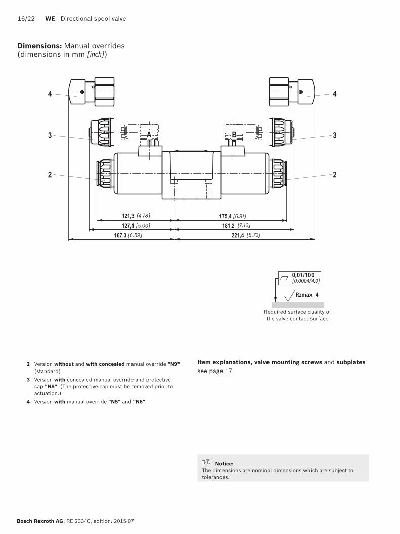
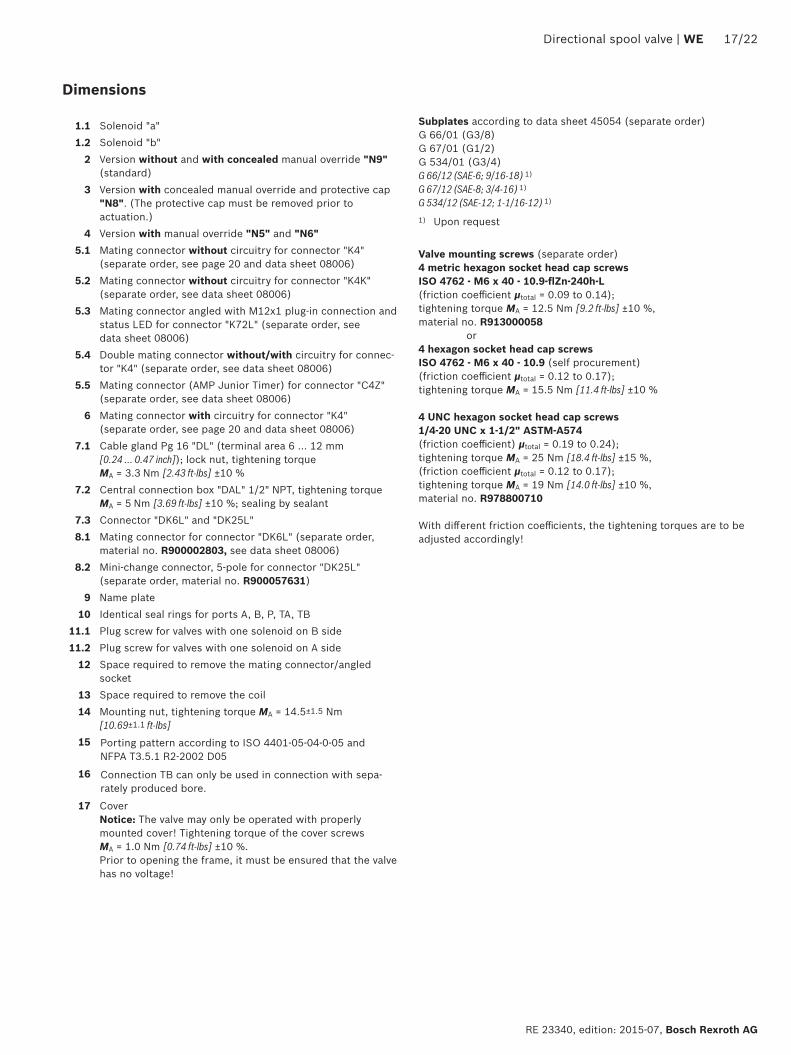
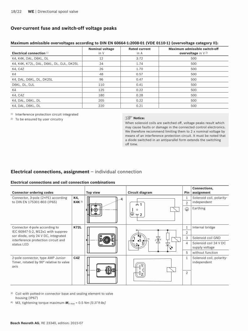
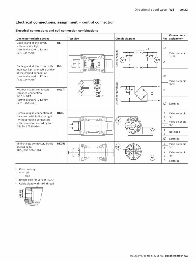
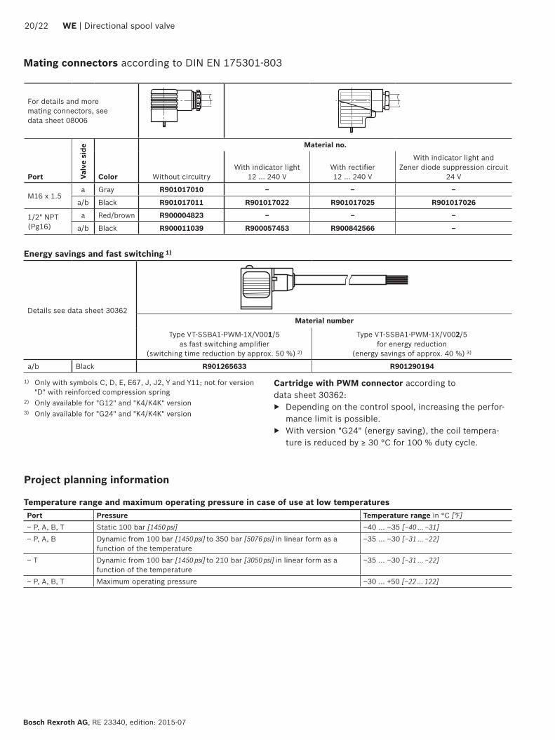

Bosch Rexroth AG RE 23340 edition 2015-07
2222 WE | Directional spool valve
Bosch Rexroth AG HydraulicsZum Eisengieszliger 197816 Lohr am Main Germany Phone +49 (0) 93 52thinspthinsp18-0 documentationboschrexrothde wwwboschrexrothde
copy This document as well as the data specifications and other information set forth in it are the exclusive property of Bosch Rexroth AG It may not be reproduced or given to third parties without its consentThe data specified above only serve to describe the product No statements concerning a certain condition or suitability for a certain application can be derived from our information The information given does not release the user from the obligation of own judgment and verification It must be remembered that our products are subject to a natural process of wear and aging
Notes
Bosch Rexroth AG HydraulicsZum Eisengieszliger 197816 Lohr am Main Germany Phone +49 (0) 93 52thinspthinsp18-0 documentationboschrexrothde wwwboschrexrothde
copy This document as well as the data specifications and other information set forth in it are the exclusive property of Bosch Rexroth AG It may not be reproduced or given to third parties without its consentThe data specified above only serve to describe the product No statements concerning a certain condition or suitability for a certain application can be derived from our information The information given does not release the user from the obligation of own judgment and verification It must be remembered that our products are subject to a natural process of wear and aging
Directional spool valve | WE 2322
RE 23340 edition 2015-07 Bosch Rexroth AG
Notes
Bosch Rexroth AG RE 23340 edition 2015-07
2422 WE | Directional spool valve
Notes
- Features
- Contents
- Ordering codes
- Symbols
- Function section
- Technical data
- Characteristic curves
- Performance limits
- Dimensions
- Over-current fuse and switch-off voltage peaks
- Electrical connections assignment ndash individual connection
- Mating connectors
- Project planning information
- Additional information
-