Directional control valves catalogue NVD2 - · PDF fileDirectional control valves Cavity up to...
32
Directional control valves catalogue NVD2 - NVS3 Edition 04/2016
Transcript of Directional control valves catalogue NVD2 - · PDF fileDirectional control valves Cavity up to...

Directional control valves catalogue NVD2 - NVS3
Edition 04/2016

Company profile 2
NVD2 flow sensing directional control valves 5
NVS3-IS, NVS3-IPC on/off SAE 10 directional control valves 25
NVS3-LS SAE 10 load sensing directional control valve 43
Table of contents
16.04www.nem-hydraulics.com 11

Directional Control ValvesFlow sensing (patented) pmax 350 barLoad sensing Qmax 40 L/min Ports BSP 3/8“
Mechanical and Electrical Cartridge ValvesPressure control valves pmax 350 barCounterbalance valves Qmax 200 L/minDirectional control valves Cavity up to SAE 16Flow control valves M27x1,5
Hydraulic Integrated CircuitsWeight lifting pmax 350 barEarth moving Qmax 200 L/minAgricultural vehicles Industrial vehicles
Parts-in-Body ValvesCounterbalance valves pmax 410 barPO check valves Qmax 500 L/minBoom lowering control valves Ports up to11/4 SAE6000Pressure control valves Flow control valves
Company profile
NEM, founded in 1995, is a valve manufac-turer specialising in the development of hy-draulic solutions for mobile, agricultural and industrial applications.
Our goal is to be a reliable partner, providing for our customers a state of the art service, delivered by highly qualified technical staff, to achieve customized solutions.
At NEM we are aware that the future of the hydraulic industry is in system engineering. We are therefore developing and manufac-turing top quality products, which can be fully integrated into many different applica-tions. NEM components ensure the high-est level of performance and safety in any application; this, together with our focus on innovation, has gained us the trust and ap-preciation of leading machine manufactur-ers worldwide.
NEM firmly believes that its internal synergy ensures that all customers receive the most efficient and effective service. This is why, each and every day, we explore advances in industry related knowledge, discuss solu-tions, and bring into play all our expertise to ensure we are utilizing the most advanced technologies.
In order to provide our customers with the highest possible quality, NEM employs some of the most skilled professionals with-in the industry, who work state of the art equipment and processes. This garantuees perfect functionality of components and sys-tems produced at our facilities.
NEM´s philosophy has always been qual-ity driven, with the customer first in mind. At NEM we understand that human capital is the most important resource and main reason for our joint success. Our company believes in people, in their talents and their personal expertise.
We source raw material and parts, develop and design components and systems, ma-chine them using processes such as turn-ing, grinding, lapping, drilling, honing, heat treatment, assemble and test and finally de-liver to our customer´s specifications.
It´s our responsibility to take care of our cus-tomers as well as ensure total quality. NEM´s capabilities cover a wide spectrum of control technologies by combining me-chanics, electrics and electronics to supply perfect hydraulic operating components and systems.
Hundreds of customers in many industries trust us and have taken advantage of our expertise. Our applications can be found all over the globe, under the heaviest working conditions.
It goes without saying that in NEM people go the extra mile in order to satisfy our cus-tomers and the customer of our customers.
You are kindly invited to meet the people at NEM who listen and who deliver for the ben-efit of our customers.
16.04 16.04www.nem-hydraulics.com www.nem-hydraulics.com2 32 3

16.04 16.04www.nem-hydraulics.com www.nem-hydraulics.com4 5
Directional Control Valves
Flow Sensing Valves, NVD2Ports A/B BSP 3/8“ | pmax 350 bar | Inlet Qmax 50 L/min
Features
> Flow Sensing (patented)
> Load independent flow control
> Good stability combined with counterbalance valves
> Electro-proportional hydraulic actuation
> Open-centre (closed centre available on request)
> Modular design
Function
NVD2 is a highly innovative directional control valve, which paves the way into the world of proportional valves. NVD2 technology (patented) impressively links constructive simpli-city and high functional performance; a simple and compact design, typical of the more traditional open-centre directional control valves.
It is associated with an extremely precise control, indepen-dent from the load conditions and simultaneous movements. The flow sensing principle is efficient when electrically ope-rated. It reaches its maximum potential when used in combi-nation with radio remote control or electronic control devices.
NVD2/4, example of customized configuration
The flow sensing principle is based on the equilibrium bet-ween the metered oil flow and the electro-proportional actu-ation forces, so this direct feedback makes the flow control independent from loads and simultaneous movements.
Directional control valve NVD2 is availiable in its standard version for fixed displacement pumps, on request it can be also configured for variable displacement pumps.
With fixed displacement pumps, the open centre achitecture allows a very low system pressurization at stand-by condition.
1 Spool
2 Electro-proportional hydraulic control
3 Flow control poppet
4 Anti-shock valve
5 Plug for anti-shock valve replacement
2
1
3
4 5

16.04 16.04www.nem-hydraulics.com www.nem-hydraulics.com6 7
Directional Control Valves | Flow Sensing Valves NVD2 Directional Control Valves | Flow Sensing Valves NVD2
6 7
Model code
Ordering example
1 NVD2 with 1 work section NVD2/1 Page
A Inlet section IL-VM(180)-VP-VR 8
B Work section #1 1) D2-W001A-A12/B24-XE-M12D-H05-F01-C2A(180)/TCB 10
C Outlet section ZN-EV-C12D 14
Port location and size (inlet/outlet sections) U1-G 16
Fixing SS 16
A
B
C
The ordering configuration is generated by assembling a string of codes that allow to define the valve assembly.
This string is made by defining the inlet section first, then the work sections and at the end the outlet section and fixing devices.
See below an example of NVD2 model code and on the fol-lowing pages the options for each block of strings.
1) The work section string configuration must be repeated as many times as the number of work sections composing the control valve.
Hydraulic circuit
Configuration exampleNVD2/2
Inlet sectionIL-VM(180)-VP-VR
Work section #1D2-W001A-A12/B24-XE-M12D-H05-F01-C2A(180)/TCB
Work section #2D2-W001A-A12/B24-XE-M12D-H05-F01-C2A(180)/TCB
Outlet sectionZN-EV-C12D
Port location and sizeU1-G
FixingSS
The hydraulic layout of NVD2 flow sen-sing control valves is similar to any open-centre directional control valve.
The technological feature that makes the NVD2 operational concept similar to a load sensing directional control valve is the fact that, being electrically operated, it controls the flow indepen-dently from load conditions and the si-multaneous movements.
Manual actuator device is provided as emergency feature in case of malfunc-tion of the proportional electro-hydraulic control device: in case of malfunction, the NVD2 directional control valve acts as a normal open-centre one.
1 Spool activated by proportional electro-hydraulic control2 Proportional electro-hydraulic control3 Poppet control flow on section4 Anti-shock valve5 Plug for anti-shock valve replacement6 Pre-loading valve7 Pressure reducing valve8 General relief valve9 Electric dump valve
L
AB
AB
P1 T1
TP
9
4
2
1
1
2
6
7 8
2
2
4
3 3
33
v
M

16.04 16.04www.nem-hydraulics.com www.nem-hydraulics.com8 9
Directional Control Valves | Flow Sensing Valves NVD2 Directional Control Valves | Flow Sensing Valves NVD2
8 9
A - Ordering code: Inlet Section, cont´
Left side
1 Inlet module
2 Main pressure valve
3 Pre-loading valve
Right side
L port (G 1/4“)(drain line connected to reservoir)
.
with pressure relief valve without pressure relief valve
V port (G 1/8“)(reduced pressure)
Inlet module without pre-loading valveInlet module with pre-loading valveRecommended for inlet flow less than 25 L/min
Plug for valve replacement
Plug for valve replacement
IL
VM
VP
IR
SVM
TP
L
T
P
V
L
T
P
V
L
T
P
V
L
T
P
V
1 2 3 4
IL - VM1(100) - VP - VR
1 Inlet moduleLeft side ILRight side IR
2 Main pressure relief valve 1)
Without pressure relief valve (plug) SVMWith direct acting pressure relief valve- setting range 40 to 140 bar (pressure increase 23 bar per turn) VM1(...) 2)
- setting range 120 to 250 bar (pressure increase 31 bar per turn) VM2(...) 2)
- setting range 220 to 410 bar (pressure increase 53 bar per turn) VM3(...) 2)
3 Pre-loading valveWtih pre-loading valve (Recommended for inlet flow less than 25 L/min) VPWithout pre-loading valve TP
4 Pressure reducing valveWith pressure reducing valve (standard option) VR
1) Tamper proof cap to be ordered separately; ordering no: 90210301902) (...) Setting pressure specified at Q = 20 L/min
NVD2 inlet module has a P power supply connection and a T connection so that the connection to the reservoir can be easily chosen either at the DCV inlet or outlet. The module is equipped with a general pressure relief valve and it integra-tes the pressure reducing valve (18 bar) for power supply to the proportional electro-hydraulic controls. The pressure re-
A - Ordering code: Inlet Section
ducing valve is equipped with a 30 µm filter for the protection of the proportional electro-hydraulic valves. At user’s choice, the input module can host a pre-loading valve. This valve is used to keep the standby pressure at a suitable level in order to have a quick reaction by the proportional electro-hydraulic controls.
1 Inlet module
2 Main pressure relief valve
3 Pre-loading valve
4 Pressure reducing valve2
3
4
1
16.04 16.04www.nem-hydraulics.com www.nem-hydraulics.com10 11
Directional Control Valves | Flow Sensing Valves NVD2 Directional Control Valves | Flow Sensing Valves NVD2
10 11
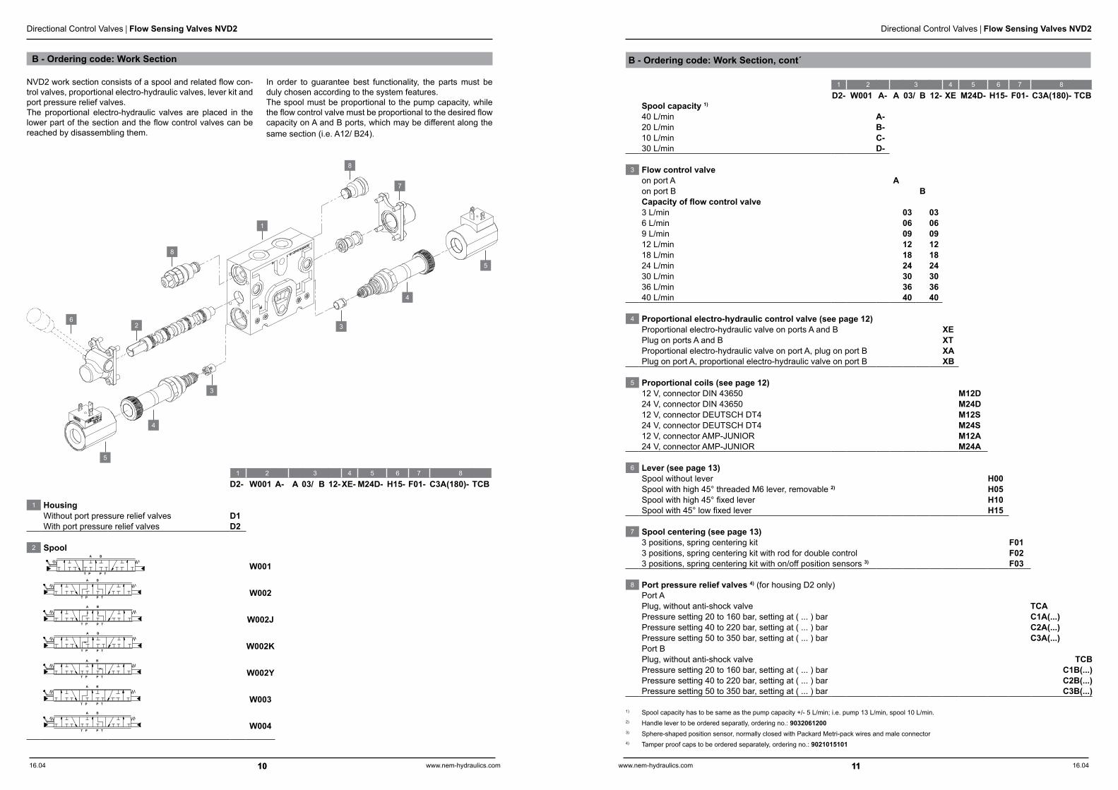
1 2 3 4 5 6 7 8
D2- W001 A- A 03/ B 12- XE M24D- H15- F01- C3A(180)- TCBSpool capacity 1)
40 L/min A-20 L/min B-10 L/min C-30 L/min D-
3 Flow control valveon port A Aon port B BCapacity of flow control valve3 L/min 03 036 L/min 06 069 L/min 09 0912 L/min 12 1218 L/min 18 1824 L/min 24 2430 L/min 30 3036 L/min 36 3640 L/min 40 40
4 Proportional electro-hydraulic control valve (see page 12)Proportional electro-hydraulic valve on ports A and B XEPlug on ports A and B XTProportional electro-hydraulic valve on port A, plug on port B XAPlug on port A, proportional electro-hydraulic valve on port B XB
5 Proportional coils (see page 12)12 V, connector DIN 43650 M12D24 V, connector DIN 43650 M24D12 V, connector DEUTSCH DT4 M12S24 V, connector DEUTSCH DT4 M24S12 V, connector AMP-JUNIOR M12A24 V, connector AMP-JUNIOR M24A
6 Lever (see page 13)Spool without lever H00Spool with high 45° threaded M6 lever, removable 2) H05Spool with high 45° fixed lever H10Spool with 45° low fixed lever H15
7 Spool centering (see page 13)3 positions, spring centering kit F013 positions, spring centering kit with rod for double control F023 positions, spring centering kit with on/off position sensors 3) F03
8 Port pressure relief valves 4) (for housing D2 only)Port APlug, without anti-shock valve TCAPressure setting 20 to 160 bar, setting at ( ... ) bar C1A(...)Pressure setting 40 to 220 bar, setting at ( ... ) bar C2A(...)Pressure setting 50 to 350 bar, setting at ( ... ) bar C3A(...)Port BPlug, without anti-shock valve TCBPressure setting 20 to 160 bar, setting at ( ... ) bar C1B(...)Pressure setting 40 to 220 bar, setting at ( ... ) bar C2B(...)Pressure setting 50 to 350 bar, setting at ( ... ) bar C3B(...)
1) Spool capacity has to be same as the pump capacity +/- 5 L/min; i.e. pump 13 L/min, spool 10 L/min.2) Handle lever to be ordered separatly, ordering no.: 90320612003) Sphere-shaped position sensor, normally closed with Packard Metri-pack wires and male connector4) Tamper proof caps to be ordered separately, ordering no.: 9021015101
B - Ordering code: Work Section, cont´
1 2 3 4 5 6 7 8
D2- W001 A- A 03/ B 12-XE- M24D- H15- F01- C3A(180)- TCB
1 HousingWithout port pressure relief valves D1With port pressure relief valves D2
2 SpoolA B
T P P T
W001
T P P T
A B
W002
T P P T
A B
W002J
T P P T
A B
W002K
T P P T
A B
W002Y
T P P T
A B
W003A B
P TT PW004
1
2
3
3
4
4
5
5
6
7
8
8
NVD2 work section consists of a spool and related flow con-trol valves, proportional electro-hydraulic valves, lever kit and port pressure relief valves. The proportional electro-hydraulic valves are placed in the lower part of the section and the flow control valves can be reached by disassembling them.
In order to guarantee best functionality, the parts must be duly chosen according to the system features. The spool must be proportional to the pump capacity, while the flow control valve must be proportional to the desired flow capacity on A and B ports, which may be different along the same section (i.e. A12/ B24).
B - Ordering code: Work Section

16.04 16.04www.nem-hydraulics.com www.nem-hydraulics.com12 13
Directional Control Valves | Flow Sensing Valves NVD2 Directional Control Valves | Flow Sensing Valves NVD2
12 13
Lever and spool centering
H10 H15
H00
H05
F01
F03
F02
6 Lever
7 Spool centering
7
6
Current range A 0,1 ÷ 5
Voltage range VDC 5 ÷ 24
Temperature range °C -30 ÷ 120
Connector Packard Metri-pack
NC contact1) Sensor features: sphere-shaped position sensor,usually closed with Packard Metri-pack wires and male connector.
Operation without lever
Operation with high 45°M6 threadHand lever has to be ordered separately (ordering no. 9032061200)
Operation with high 45°fixed lever
Operation with low 45°fixed lever
3 positions,spring centering kit
3 positions,spring centering kit with rod for double operation (M8 thread)
3 positions,spring centering kitwith on/off position sensors 1)
Proportional electro-hydraulic valves NVD2 must be driven by PWM signal. By adjusting the maximum current value, it is possibile to set the maximum flow supplied from each port.
In order to reduce control hysteresis as much as possible and guarantee the most reactive operation, it is recommended to set the PWM carrier frequency at 60 Hz and anyhow not ex-ceed 90 Hz.
port Aport B
5
5
4
4
4 Proportional electro-hydraulic control valve
5 Proportional coils
Proportional electro-hydraulic control valve
Technical data (Measured with mineral oil HLP to DIN 51524 of 46 cSt and at 40 OC oil temperature.)
HydraulicPilot pressure bar 18Max. back pressure on port L (connected to reservoir) bar 2ElectricCoil power at 20 °C W 36Ambient temperature °C -20 to 40Thermal insulation class (coil) FWire insulation class H (>185 °C)ED % 100Connector type and protection class 1) DIN 43650 IP 65
DEUTSCH DT4 IP 67 AMP JUNIOR IP 67
Voltage supply VDC 12 24Resistance Ω 3,9 14,5Max. current at duty cycle 100% A 1,8 0,9Hysteresis (current) % 5Recommended PWM frequency Hz 60 ÷ 90
Note: For applications outside technical data please contact NEM customer care.

16.04 16.04www.nem-hydraulics.com www.nem-hydraulics.com14 15
Directional Control Valves | Flow Sensing Valves NVD2 Directional Control Valves | Flow Sensing Valves NVD2
14 15
Dump valve and coil
Outlet section with dump valve
Outlet section with plug (without dump valve)
Push and twist button
Push button
No emergency
EV0 EV4 EV5
ET
Inlet M (G 1/4“)(main pressure gauge)
Tightening torque 40 Nm
Cartridge tightening torque 40 Nm
Inlet M (G 1/4“)(manometer)
Technical data (Measured with mineral oil HLP to DIN 51524 of 46 cSt and at 40 OC oil temperature.)
HydraulicMax. flow rate L/min 60Max. working pressure bar 350Total leakage cm3/min 0,25Seals NBR or PTFECavity C230000ElectricCoil power at 20 °C W 24Ambient temperature °C -20 to 40Thermal insulation class (coil) HWire insulation class H (>185 °C)ED % 100
Connector type and protection class (Connector assembled)
DIN 43650 IP 65DEUTSCH DT4 IP 67AMP JUNIOR IP 67
Voltage supply VDC 12 24Resistance Ω 6,8 24
Note: For applications outside technical data please contact NEM customer care.
P1
T1
M
M
T1
P1
Ring nuttightening torque 5 Nm
1 2 3
ZN- EV4- C24D
1 Outlet section ZN
2 Dump valvePlug (without dump valve) ETDump valve without emergency operation EV0Dump valve with emergency push button EV4Dump valve wtith emergency push and twist button EV5
3 Coil (dump valve)12 V, connector DIN 43650 C12D24 V, connector DIN 43650 C24D12 V, connector DEUTSCH DT4, with diode C12S24 V, connector DEUTSCH DT4, with diode C24S12 V, connector AMP-JUNIOR C12A24 V, connector AMP-JUNIOR C24A
The NVD2 outlet section allow to manage a second return port and the possibility to install an electric dump valve that ensures, in the absence of power supply, the entire distribu-tor can not be operated.
Besides, the outlet section can be configured for carry-over connection feature, that allows to install NVD2 in serial with other hydraulic devices.
3
2
2
1
C - Ordering code: Outlet section

16.04 16.04www.nem-hydraulics.com www.nem-hydraulics.com16 17
Directional Control Valves | Flow Sensing Valves NVD2 Directional Control Valves | Flow Sensing Valves NVD2
16 17
Technical data (Measured with mineral oil HLP to DIN 51524 of 46 cSt and at 40 OC oil temperature.)
GeneralWork sections 8 max.Mounting type With fixing holes, Type SS
With mounting brackets, type CSMounting position AnySpool stroke mm 5,5 + 5,5Spool operating force daN 8 to 28Lever adjustment ° ±19Dead band mm 1 + 1Ambient temperature °C -25 to 80Seals NBR or PTFEHydraulicHydraulic fluid Mineral oil HLP to DIN 51524Fluid temperature range °C -20 to 90Viscosity range mm2/s 10 to 460Contamination level NAS 1638 class 9 (20/18/15 ISO 4406:1999)Filtration degree µm 20Filtration level β10 ≥ 75Max. flow rate ports P, P1 L/min 50Max. flow rate ports A, B L/min 40Internal leakage A/B to T cm3/min 20
Max. operating pressure bar 350
Max. back pressure at ports T, T1 bar 10Max. pressure at port L bar 2
T P
L
P T1 P1
L
P P1
T
L
T1
L
P
L
1 2 3
U1- G- SS
1 P and T port locationDelivery on P, discharge on T1 U1Delivery on P, discharge on T U2Delivery on P, discharge on T1, carry-over on P1 U3Delivery on P, discharge on T, carry-over on P1 U4
2 Port thread, BSP ISO 228 G
3 Mounting type 1)
Without brackets SSWith brackets CS1) For a correct installation of the valve, only 3 fixing bolts are recommended.
1 Port location
U1 U2 U3 U4
3 Mounting type
Threads to ISO 228 (BSP) Pump User Carry over Reservoir Reservoir Drain
Port P A B P1 T T1 L
Size G½“ G⅜“ G⅜ “ G½“ G½“ G¾“ G¼“
Delivery on (P)Discharge on (T1)
Delivery on (P)Discharge on (T)
Delivery on (P)Discharge on (T1)Carry-over on (P1)
Delivery on (P)Discharge on (T)
Carry-over on (P1)
2 Port threads
SS CS
With bracketsWithout brackets
Ordering code: Port location, threads, mounting type

16.04 16.04www.nem-hydraulics.com www.nem-hydraulics.com18 19
Directional Control Valves | Flow Sensing Valves NVD2 Directional Control Valves | Flow Sensing Valves NVD2
18 19
Performance characteristics (Measured with mineral oil HLP to DIN 51524 of 46 cSt and at 40 OC oil temperature.)
Flow control valve
Current in A
12
8
0,8 1,0 1,2 1,4 1,6 1,8
Flow
in L
/min
4
9 L/min
6 L/min
3 L/min
0,4 0,5 0,6 0,7 0,8 0,9
Current in A
30
20
0,8 1,0 1,2 1,4 1,6 1,8
Flow
in L
/min
10
24 L/min
18 L/min
12 L/min
0,4 0,5 0,6 0,7 0,8 0,9
Current in A
45
0,8 1,0 1,2 1,4 1,6 1,8
Flow
in L
/min
40 L/min
36 L/min
30 L/min
0,4 0,5 0,6 0,7 0,8 0,9
(24 VDC)
(24 VDC)
(24 VDC)
(12 VDC)
(12 VDC)
(12 VDC)
30
15
Performance characteristics (Measured with mineral oil HLP to DIN 51524 of 46 cSt and at 40 OC oil temperature.)
Work section (with pre-loading valve)
Main pressure relief valve
Flow in L/min0
20
15
5 10 15 20 25 403530
Pre
ssur
e dr
op in
bar
10
NVD2/8
NVD2/1
Flow in L/min0 5 10 15 20 25 403530
Pre
ssur
e dr
op in
bar 300
200
100 VM1
VM2
VM3
Port pressure relief valve
Flow in L/min
Pre
ssur
e dr
op in
bar
C1
C2
C3
Dump valve
Flow in L/min0
3
2
5 10 15 20 25 403530
Pre
ssur
e dr
op in
bar
1
0 5 10 15 20 25
300
200
100
400
0

16.04 16.04www.nem-hydraulics.com www.nem-hydraulics.com20 21
Directional Control Valves | Flow Sensing Valves NVD2 Directional Control Valves | Flow Sensing Valves NVD2
20 21
Dimensions in mm, cont´
Mounting NVD2/1 NVD2/2 NVD2/3 NVD2/4 NVD2/5 NVD2/6 NVD2/7 NVD2/8
withoutbrackets
X 104 144 184 224 264 304 344 384
Y 145 185 225 265 305 345 385 430
withbrackets
X´ 155,5 195,5 235,5 275,5 315,5 355,5 395,5 435,5
Y´ 178,5 218,5 258,5 298,5 338,5 378,5 418,5 458,5
Weight kg 10,2 13,7 17,2 20,7 24,2 27,7 31,2 34,7
2040
411
69
4020
Y
4040
4040
9 9
X8
04
35
54
Y'
X'
N°4 Holes M8 prof.10
Port "L"
PT
ABP
1
T1
411
103
192
87
403
171
5
18°
18°134,7
0
327
7
193,
50
253,50
120
T P
N°4 Slots Ø 9
8
AA
AA
BB
BB
Dimensions in mm

16.04 16.04www.nem-hydraulics.com www.nem-hydraulics.com22 23
Directional Control Valves | Flow Sensing Valves NVD2 Directional Control Valves | Flow Sensing Valves NVD2
22 23
Spare parts, cont´
Type Ordering code
17 Tie rod kit for mountingwithout brackets
1 spool 9296081401
2 spools 9296081801
3 spools 9296082201
4 spools 9296082601
5 spools 9296083001
6 spools 9296083401
7 spools 9296083801
8 spools 9296084201
18 Tie rod kit for mountingwith brackets
1 spool 9296081402
2 spools 9296081802
3 spools 9296082202
4 spools 9296082602
5 spools 9296083002
6 spools 9296083402
7 spools 9296083802
8 spools 9296084202
19 Seal kitsInput section
9NVD20000001
Intermediate section9NVD20000003
General pressure relief valve9NVD20000004
Pressure reducing valve,pre-loading valve
9NVD20000005
Port pressure relief valve9NVD20000006
All closed SAE 10/2 plug9NVD20000007
Pilot valve9NVD20000008
Pilot valve replcaement plug9NVD20000009
Dump valve9NVD20000010
Symbol Type (L/min) Ordering code
A B
T P P T
W001A 40 3114160101
W001B 20 3114160107
W001C 10 3114160106
W001D 30 3114160100
T P P T
A B
W002A 40 3114160105
W002B 20 3114160111
W002C 10 3114160110
W002D 30 3114160103
T P P T
A B
W002JA 40 3114160102
W002JB 20 3114160109
W002JC 10 3114160108
W002JD 30 3114160104
20 Spool
3 4
1
6
2
7
8
9
10
11
11
5
20
6
7
8
18
12
13
14
15
1 Inlet moduleIL 913NEM4010
IR 913NEM4010
2 Main pressure relief valveSVM 9273274600
VM1 0023310000
VM2 0023320000
VM3 0023330000
3 Pre-loading valveSP N320271003
VP N320271002
4 Pressure reducing valveVR N320271001
5 Work sectionD1 913NEM5000
D2 913NEM5010
6 ShuttersA03, B03 3207111307
A06, B06 3207111306
A09, B09 3207111309
A12, B12 3207111300
A18, B18 3207111308
A24, B24 3207111301
A30, B30 3207111312
A36, B36 3207111302
A40, B40 3207111304
7 Proportional electro-hydraulic control valve
XT 9275225000
XE 0PNV200004
8Coil for proportional
electro-hydraulic control valve
M12D 095001191
M24D 095002191
M12S 095101190
M24S 095102190
M12A 095201190
M24A 095202190
9 LeverH00 9231400340
H059228130357
hand lever 9032061200
H10 9038011322
H15 9038031522
10 Spool centering
F019231400340
9290050231
F02 9231400501
F03 9231400504
11 Port relief valveTC 9273193600
C1 0022010000
C2 0022020000
C3 0022030000
12 Outlet moduleZN 913NEM6010
13 Dump valveET 9273274600
EV0 0553010000
EV4 0553010400
EV5 0553010500
14 Coil for dump valveC12D 098011190
C24D 098012190
C12S 098111190
C24S 098112190
C12A 098211190
C24A 098212190
15 Plug for carry-over4293130130
Type Ordering code Type Ordering code Type Ordering code
17
Spare parts

16.04 16.04www.nem-hydraulics.com www.nem-hydraulics.com24 25
Directional Control Valves
24
Directional Control Valves
On/off directional control valves,NVS3-IS, NVS3-IPCPorts size BSP 3/8“ | pmax 210 bar | Qmax 30 L/min
Features
Proportional inlet flow control (NVS3-IPC)
Anodized aluminum
Port pressure relief valves
Emergency manual levers
Lever sensor switches
NVS3/3, Example of customized configuration
Function
NVS3 is a range of compact electric directional control valves (DCV) designed for mobile applications where weight and di-mensions are key factors.Its architecture is based on the combination of SAE 10 DCV cartridges screwed into modular aluminum manifolds.Thanks to its modular design it is possible to assemble up to 8 sections of 4 way, 3 position on-off solenoid valves ar-ranged in parallel and feed by on-off or proportional electro-hydraulic inlet elements.The inlet elements can be configured with many options as: different type of pressure relief valves, dump valves, load in-dependent proportional flow control, carryover by-pass line.On request, it can be easily customized to integrate specific features.

16.04 16.04www.nem-hydraulics.com www.nem-hydraulics.com26 27
Directional Control Valves | On/off Directional Control Valves NVS3-IS, NVS3-IPC Directional Control Valves | On/off Directional Control Valves NVS3-IS, NVS3-IPC
26 27
Hydraulic circuit: NVS3-IPC
Proportional inlet section type configuration
Configurationexample NVS3/5
Inlet section IPC-NA0-D12D-06(180)-08-83-P12DWork section #1 WS-1U-C12DWork section #2 WS-2U-C12DWork section #3 WS-2U-C12DWork section #4 WSU-2U-C12D-A/NA5-D12D-B/NA5-D12DWork section #5 WSU-1U-C12D-A/C2(100)-B/C2(100)
M P T
A
B
A
B
A
B
A
B
B
A
100 bar
180 bar
100 bar
Hydraulic circuit: NVS3-IS
On/off inlet section type configuration
Configurationexample NVS3/6
Inlet section IS-NA0-D12D-06(180)Work section #1 WS-1D-C120Work section #2 WSU-1D-C12D-A/NP-B/NPWork section #3 WS-10-C12DWork section #4 WS-20-C12DWork section #5 WSU-2U-C12D-A/NP-B/NA5-D12DWork section #6 WSU-2U-C12D-A/C2(170)-B/NP
A
B
B
A
B
A
B
A
B
A
B
A
TPM
170 bar
180 bar

16.04 16.04www.nem-hydraulics.com www.nem-hydraulics.com28 29
Directional Control Valves | On/off Directional Control Valves NVS3-IS, NVS3-IPC Directional Control Valves | On/off Directional Control Valves NVS3-IS, NVS3-IPC
28 29
A -Ordering code: Inlet section, cont´
1 2 3 4 5 6 7
IPC- NA0- D12D- 06(180)- 08- 83- P12D
1 ConfigurationOn/off ISProportional IPC
2 Dump valvePlug (w/o dump valve) NPDump valve NA0Dump valve with push emergency feature NA4Dump valve with push and twist emergency feature NA5
3 Coil (dump valve)12 V, connector DIN 43650 D12D24 V, connector DIN 43650 D24D12 V, connector DEUTSCH DT4, with diode D12S24 V, connector DEUTSCH DT4, with diode D24S12 V, connector AMP-JUNIOR D12A24 V, connector AMP-JUNIOR D24A
4 Pressure relief valve (spring type and setting)Plug (w/o pressure relief valve) NPDirect acting, Qmax 30 L/minPressure setting range 15 to 50 bar, setting at (...) 04(...)Pressure setting range 50 to 120 bar, setting at (...) 05(...)Pressure setting range 120 to 200 bar, setting at (...) 06(...)Pressure setting range 200 to 350 bar, setting at (...) 1) 07(...)
5 Hydraulic compensator 2)
Cracking pressure 8 bar 08
6 Electro-proportional flow regulator 2)
Max. regulated flow rate 9 L/min, with lever 33Max. regulated flow rate 15 L/min, with lever 53Max. regulated flow rate 25 L/min, with lever 83Max. regulated flow rate 30 L/min, with lever 03Max. regulated flow rate 9 L/min, with lever and detent 36Max. regulated flow rate 15 L/min, with lever and detent 56Max. regulated flow rate 25 L/min, with lever and detent 86Max. regulated flow rate 30 L/min, with lever and detent 06Max. regulated flow rate 9 L/min, with handknob 37Max. regulated flow rate 15 L/min, with handknob 57Max. regulated flow rate 25 L/min, with handknob 87Max. regulated flow rate 30 L/min, with handknob 07
7 Coil for electro-proportional flow regulator 2)
No coil 0012 V, connector DIN 43650 P12D24 V, connector DIN 43650 P24D12 V, connector DEUTSCH DT4 P12S24 V, connector DEUTSCH DT4 P24S12 V, connector AMP-JUNIOR P12A24 V, connector AMP-JUNIOR P24A
1) For NVS3: Maximum pressure setting 210 bar.2) For configuration IPC only.
A - Ordering code: Inlet section
Ordering example for complete valve
Valve with 2 work sections NVS3/2
A Inlet section IS-NA0-D12D-06(180)
B Work section #1 WS-1U-C12D
Work section #2 WSU-1U-C12D-A/C2(170)-B/C2(170)
On/off configuration, Type IS
Proportional configuration, Type IPC
M
P
T
T
P
M
2
4
1
3
2
41
3
6
5
7
1
2
3
4
1
2
3
4 5
7
6
The ordering configuration is generated by assembling a string of codes that allow to define the valve assembly.This string is made by defining the inlet section first, then the working sections.See above an example and in the following pages the options for each block of strings.

16.04 16.04www.nem-hydraulics.com www.nem-hydraulics.com30 31
Directional Control Valves | On/off Directional Control Valves NVS3-IS, NVS3-IPC Directional Control Valves | On/off Directional Control Valves NVS3-IS, NVS3-IPC
30 31
B - Ordering code: Work Section, cont´
1 2 3 4 5 6 / 7 8 5 6 / 7 8
WSU- 1 U- C12D- A/ C1(80)- B/ NA4- D12D
1 HousingWithout anti-shock valve and dump valve WSPrepared for anti-shock valve and/or dump valve WSU
2 Spool
1
2
NP
3 Emergency operationWithout emergency operation 0Lever up ULever down D
4 Coils (cartridge valve)No coil (when Spool „NP“) 0012 V, connector DIN 43650 C12D24 V, connector DIN 43650 C24D26 V, connector DIN 43650 C26D220 V Rac 1), connector DIN 43650 C220D12 V, connector DEUTSCH DT4, with diode C12S24 V, connector DEUTSCH DT4, with diode C24S12 V, connector AMP-JUNIOR, with diode C12A24 V, connector AMP-JUNIOR, with diode C24A
5 PortsSide A A/Side B B/
6 Port relief valvesPlug, without anti-shock valve NP NPDirect operated, setting range 20 to 160 bar, setting at ... bar C1(...) C1(...)Direct operated, setting range 40 to 220 bar, setting at ... bar C2(...) C2(...)Direct operated, setting range 50 to 350 bar, setting at ... bar C3(...) C3(...)
7 Dump valvesPlug, without dump valveWithout emergency operation NA0 NA0Push emergency operation NA4 NA4Push and twist emergency operation NA5 NA5
8 Coils (dump valve)12 V, connector DIN 43650 D12D D12D24 V, connector DIN 43650 D24D D24D12 V, connector DEUTSCH DT4, with diode D12S D12S24 V, connector DEUTSCH DT4, with diode D24S D24S12 V, connector AMP-JUNIOR, with diode D12A D12A24 V, connector AMP-JUNIOR, with diode D24A D24A
1) Rectifer not included; power 25 W
T
B
P
A
T
B
P
A
T
B
P
A
PLUGGED
B - Ordering code: Work Section
2
1
3
A B
21
3
44
A B
2
1
4
3
2
1
3
4
User - port A
User- port B
User - port A
User - port B
67
8

16.04 16.04www.nem-hydraulics.com www.nem-hydraulics.com32 33
Directional Control Valves | On/off Directional Control Valves NVS3-IS, NVS3-IPC Directional Control Valves | On/off Directional Control Valves NVS3-IS, NVS3-IPC
32 33
Technical data, cont´ (Measured with mineral oil HLP to DIN 51524 of 46 cSt and at 40 OC oil temperature.)
Electro-Proportional flow regulator P12D P24D P12S P24S P12A P24A
Coil tube diameter mm 19
Thermal insulation class HWire insulation class H(>185°)ED % 100Coil power at 20°C W 36Ambient temperature °C -20 to 40Connector type DIN 43650 DEUTSCH DT4 AMP-JUNIORVoltage supply 12 24 12 24 12 24Resistance 3,9 14,5 3,9 14,5 3,9 14,5Max. current 0,9 1,8 0,9 1,8 0,9 1,8Protection class IP 65 IP 67 IP 65Circuit Standard With diodePWM Hz 60 - 90Hysteresis % 5
On/off cartridge valve (working section) C12D C24D C26D C220D C12S C24S C12A C24ATotal leakage cm3/min 100Coil tube diameter mm 19Thermal insulation class HWire insulation class H (> 185 °C)ED % 100Coil power at 20 °C W 24Ambient temperature °C -20 to 40Connector type DIN 43650 DEUTSCH DT4 AMP-JUNIORVoltage supply VDC 12 24 26 220 Rac ** 12 24 12 24Resistance Ω 6,8 24 27,1 1470 6,8 24 6,8 24Protection class IP 65 IP 67 IP 65Circuit Standard With diode
Technical data (Measured with mineral oil HLP to DIN 51524 of 46 cSt and at 40 OC oil temperature.)
GeneralMax. inlet flow rate L/min 30Max. working pressure bar 210Work sections 8 max.Mounting type Mounting brackets and fixing holesMounting position AnyAmbient temperature °C -20 to 50Seals NBR or PTFEHydraulicHydraulic fluid Mineral oil HLP to DIN 51524Fluid temperature range °C -20 to 90Viscosity range mm2/s; cSt 15 to 250Contamination level NAS 1638 class 9 (20/18/15 ISO 4406:1999)Filtration degree µm 20Filtration level β20 ≥ 75Max. back pressure bar 20
Dump valve (Coil) D12D D24D D12S D24S D12A D24ACoil tube diameter mm 13Thermal insulation class HWire insulation class H (> 185 °C)ED % 100Coil power at 20 °C W 20,5Ambient temperature °C -20 to 40Connector type DIN 43650 DEUTSCH DT4 AMP-JUNIORVoltage supply VDC 12 24 12 24 12 24Resistance Ω 7 28 7 28 7 28Protection class IP65 IP67 IP65Circuit Standard With diode Standard
Pressure relief valveType Direct actingMax. flow rate L/min 30Max. working pressure bar 350Pressure setting range type 04 bar 15 to 50
type 05 bar 50 to 120type 06 bar 120 to 200type 07 bar 200 to 350

16.04 16.04www.nem-hydraulics.com www.nem-hydraulics.com34 35
Directional Control Valves | On/off Directional Control Valves NVS3-IS, NVS3-IPC Directional Control Valves | On/off Directional Control Valves NVS3-IS, NVS3-IPC
34 35
Performance characteristics: Work section (Measured with mineral oil HLP to DIN 51524 of 46 cSt and at 40 OC oil temperature.)
Dump valve (ports A/B)
Port relief valve (ports A/B)
Spool 1
Spool 2
0
50
100
150
200
250
300
350
400
450
0 5 10 15 20 25
Pres
sure
dro
p in
bar
Flow in L/min
0
2
4
6
0 5 10 15 20 25 30 35 40
Pres
sure
dro
p in
bar
Flow in L/min
0
5
10
15
20
25
0 5 10 15 20 25 30
Pres
sure
dro
p in
bar
Flow in L/min
0
5
10
15
20
25
0 5 10 15 20 25 30
Pres
sure
dro
p in
bar
Flow in L/min
Options C1,C2,C3
1 2
1 2
T
B
P
A
T
B
P
A
Performance characteristics: Inlet section (Measured with mineral oil HLP to DIN 51524 of 46 cSt and at 40 OC oil temperature.)
Dump valve
Hydraulic compensator
Pressure relief valve
7 bar pressure drop
Options 04,05,06,07 (Qmax 30 L/min)
Proportional flow regulator
0
50
100
150
200
250
0 5 10 15 20 25 30
Pres
sure
dro
p in
bar
Flow in L/min
0
2,5
5
7,5
10
12,5
15
0 5 10 15 20 25 30 35 40
Pres
sure
in b
ar
Flow in L/min
0
2
4
6
0 5 10 15 20 25 30 35 40
Pre
ssur
e dr
op in
bar
Flow in L/min
0
5
10
15
20
25
30
35
0 0,1 0,2 0,3 0,4 0,5 0,6 0,7 0,8 0,9
Flow
in L
/min
Current in A
9 L/min
15 L/min
30 L/min
25 L/min
0 0,2 0,4 0,6 0,8 1,0 1,2 1,4 1,6 1,8
(12 VDC)(24 VDC)
1 2
1 2
3
21
2
13

16.04 16.04www.nem-hydraulics.com www.nem-hydraulics.com36 37
Directional Control Valves | On/off Directional Control Valves NVS3-IS, NVS3-IPC Directional Control Valves | On/off Directional Control Valves NVS3-IS, NVS3-IPC
36 37
Work section (Dimensions in mm)
110
80
Total Working Sections
10
10
30
10
21,5
41
18,
5
41 41 41 20,5
33
27
346
50
20,5
80
Total NVS3
122
2
8
68 8
6
44
(see page 36)
N°2 Ø9mmfixing holes
4,5 80 97
A BPort size G 3/8“ G 3/8“
Single work sectionWS WSU
Weight in kg 2,0 3,0
Total work sectionNVS3/1 NVS3/2 NVS3/3 NVS3/4 NVS3/5 NVS3/6 NVS3/7 NVS3/8
41 82 123 164 205 246 287 328
Total NVS3Inlet Section Type NVS3/1 NVS3/2 NVS3/3 NVS3/4 NVS3/5 NVS3/6 NVS3/7 NVS3/8
IS 121,5 162,5 203,5 244,5 285,5 326,5 367,5 408,5
IPC 141,5 182,5 223,5 264,5 305,5 346,5 387,5 428,5
Inlet section (Dimensions in mm)
59
42
45 17,5
44
80
63
86
14
210
4,5 80
8
8
64
8 23,5 31,5
Fixing holesM8 deep 10
IS
80
116
16
63
19,5 60
79
44
234
80 4,5
88,2
64
8
8
42
Fixing holesM8 deep 10
IPC
P T MPort size G 3/8“ G 3/8“ G 1/4“
IS IPCWeight in kg 1,7 2,8

16.04 16.04www.nem-hydraulics.com www.nem-hydraulics.com38 39
Directional Control Valves | On/off Directional Control Valves NVS3-IS, NVS3-IPC Directional Control Valves | On/off Directional Control Valves NVS3-IS, NVS3-IPC
38 39
Spare parts: Inlet Section, cont‘
33
44,
5
12,7
3/4”-16 UNF
Hex.24
Hex.19
Hex.5
Ordering code
Ordering code
Ordering code
4 Pressure relief valve
0 0 2 2 3 0 0 0 0
0 1 2 3
Setting range [bar] 15÷50 50÷120 120÷200 200÷350
Pressure increase [bar/turn] 8 20 33 59
Std. setting at 4 L/min [bar] 25 100 150 250
5 Hydraulic compensator
Note This type of valve is characterized by a dumped plunger that enable stable relief characteristics.
Ø19
Ø17,4
1
2
3
47,1
26
Hex.27
7/8”-14 UNF-2A
0 2 0 3 0 0 1 0 0
2 3
Cracking pressure [bar] 8 11
Standard
6 Electro-proportional flow regulator
Ø38
80,5
46
2Ø 17,40
3
7/8-14 UNF-2A
Hex.27
0 3 5 3 0 0 0 1
No emergency Push Button
0 3 5 8
Max. flow rate [L/min] 30 9 15 25
0 4
1 2
3
21
2
13
Spare parts: Inlet Section
0 5 5 2 0 0 0 0 0
2 Dump valve
2
4
1
3
2
41
3
6
5
7
3 Dump valve coil
Connector Protection class Coil thermal insulation class Voltage [V] Resistance [Ω] Circuit Ordering code
DIN 43650 IP65 1) H 12 7 standard 094001000
DIN 43650 IP65 1) H 24 28 standard 094002000
DEUTSCH DT4 IP67 H 12 7 with diode 094101000
DEUTSCH DT4 IP67 H 24 28 with diode 094102000
AMP - JUNIOR IP65 1) H 12 7 standard 094201000
AMP - JUNIOR IP65 1) H 24 28 standard 0942020001) Protection with connector assembled
37,7
55,5
42,5
57,5
DEUTSCH DT4 AMP - JUNIOR
37,7
33
13
42,5
16,5
with diode(Bi-directional)
Electric circuits
Standard
0 4 5
Not available
Not available
1 2
Ordering code
No emergency Push Button
Push and twist button

16.04 16.04www.nem-hydraulics.com www.nem-hydraulics.com40 41
Directional Control Valves | On/off Directional Control Valves NVS3-IS, NVS3-IPC Directional Control Valves | On/off Directional Control Valves NVS3-IS, NVS3-IPC
40 41
Spare parts: Working Section, cont‘
4 Coil (cartridge valve)
Connector Protection class Coil thermal insulation class Voltage [V] Resistance [Ω] Circuit Ordering code
DIN 43650 IP65 1) H 12 6,8 standard 098011190
DIN 43650 IP65 1) H 24 24 standard 098012190
DIN 43650 IP65 1) H 26 27,1 standard 098012191
DIN 43650 IP65 1) H 220 V Rac 2) 1470 standard 098016190
DEUTSCH DT4 IP67 F 12 6,8 with diode 098111190
DEUTSCH DT4 IP67 F 24 28 with diode 098112190
AMP - JUNIOR IP65 1) F 12 6,8 with diode 098211190
AMP - JUNIOR IP65 1) F 24 28 with diode 0982121901) Protection with connector assembled2) Rectifier not included - Power 25W
63
66
51
58,5
DEUTSCH DT4AMP - JUNIOR
With diode (Bi-directional)
Electric circuits
Standard
51
38
19
45,5
19
Ordering code3 Emergency operation: lever
0 0 1 3 0 0 0 0 1
0 3
Lever orientation up down
Up Down
6 Port relief valve
12,7
26
33
21,8
3/4"-16 UNF
Hex.10
Hex.3
Hex.20
2
1
0 0 2 2 0 1 0 0 0
1 2 3
Setting range [bar] 20÷160 40÷220 50÷350
Pressure increase [bar/turn] 36 34 63
Std. setting @ 4 l/min [bar] 50 100 250
1 2
Ordering codeOrdering code
7 Coil for electro-proportional flow regulator
Spare parts: Inlet Section, cont‘
Connector Protection class Coil thermal insulation class Voltage [V] Resistance [Ω] Circuit Ordering code
DIN 43650 IP65 1) H 12 3,9 standard 095001191
DIN 43650 IP65 1) H 24 14,5 standard 095002191
DEUTSCH DT4 IP67 H 12 3,9 standard 095101190
DEUTSCH DT4 IP67 H 24 14,5 standard 095102190
AMP - JUNIOR IP65 1) H 12 3,9 standard 095201190
AMP - JUNIOR IP65 1) H 24 14,5 standard 0952021901) Protection with connector assembled
Spare parts: Working Section
2
1
3
4
2
1
3
4
User - port A
User- port B
2 Spool (cartridge valve)
0 4 6 3 0 0 0 0
No emergency Safety leverpredisposition
0 2
Spool type 1 2
Ordering code
Spool type 1 Spool type 2
S2S1S2S1
Note: Lever and coil to be ordered separately
Ø 19
122
62
Ø 17,4P
B
S2
S1
7/8-14 UNF-2A
Hex.27
Ø 15,8
A
T
Ø38T
B
P
A
T
B
P
A
Not available
Not available
67
8
16.04 16.04www.nem-hydraulics.com www.nem-hydraulics.com42 43
Directional Control Valves | On/off Directional Control Valves NVS3-IS, NVS3-IPC
42
Directional Control Valves
Load sensing directional control valves,NVS3-LSPorts size BSP 3/8“ | pmax 210 bar | Qmax 30 L/min
Features
Load sensing
Inlet flow compensation
Modular design
Anodized aluminum
Port pressure relief valves
Emergency manual levers
Lever sensor switches
NVS3/3, Example of customized configuration
Function
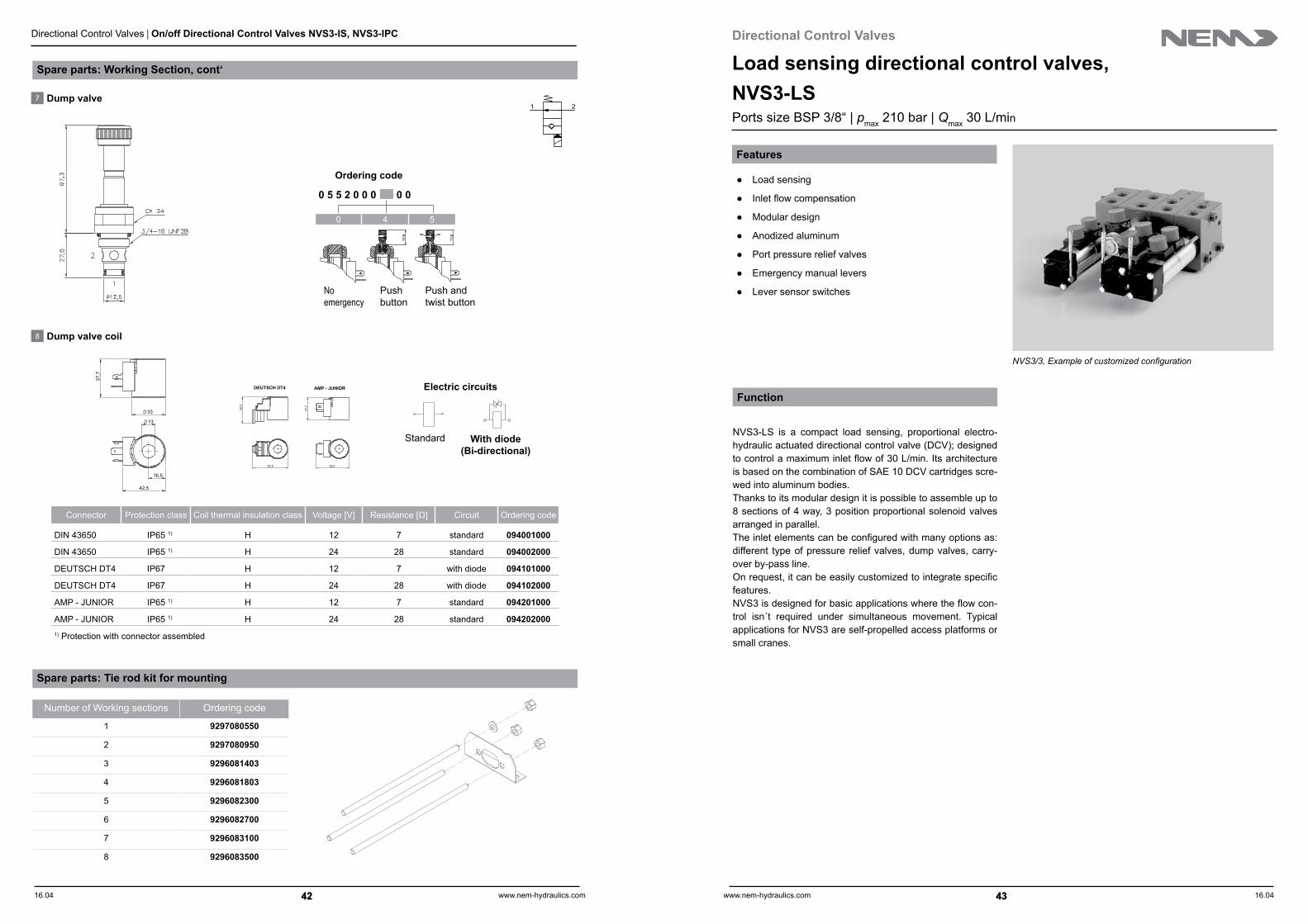
NVS3-LS is a compact load sensing, proportional electro-hydraulic actuated directional control valve (DCV); designed to control a maximum inlet flow of 30 L/min. Its architecture is based on the combination of SAE 10 DCV cartridges scre-wed into aluminum bodies. Thanks to its modular design it is possible to assemble up to 8 sections of 4 way, 3 position proportional solenoid valves arranged in parallel.The inlet elements can be configured with many options as: different type of pressure relief valves, dump valves, carry-over by-pass line.On request, it can be easily customized to integrate specific features. NVS3 is designed for basic applications where the flow con-trol isn´t required under simultaneous movement. Typical applications for NVS3 are self-propelled access platforms or small cranes.
43
Spare parts: Working Section, cont‘
0 5 5 2 0 0 0 0 0
7 Dump valve
8 Dump valve coil
Connector Protection class Coil thermal insulation class Voltage [V] Resistance [Ω] Circuit Ordering code
DIN 43650 IP65 1) H 12 7 standard 094001000
DIN 43650 IP65 1) H 24 28 standard 094002000
DEUTSCH DT4 IP67 H 12 7 with diode 094101000
DEUTSCH DT4 IP67 H 24 28 with diode 094102000
AMP - JUNIOR IP65 1) H 12 7 standard 094201000
AMP - JUNIOR IP65 1) H 24 28 standard 0942020001) Protection with connector assembled
37,7
55,5
42,5
57,5
DEUTSCH DT4 AMP - JUNIOR
37,7
33
13
42,5
16,5
0 4 5
1 2
Ordering code
Noemergency
Pushbutton
Push andtwist button
With diode (Bi-directional)
Electric circuits
Standard
Number of Working sections Ordering code
1 9297080550
2 9297080950
3 9296081403
4 9296081803
5 9296082300
6 9296082700
7 9296083100
8 9296083500
Spare parts: Tie rod kit for mounting

16.04 16.04www.nem-hydraulics.com www.nem-hydraulics.com44 45
Directional Control Valves | Load Sensing Directional Control Valves NVS3-LS Directional Control Valves | Load Sensing Directional Control Valves NVS3-LS
44 45
A - Ordering code: Inlet section
Ordering example for complete valve
A Valve with 2 work sections NVS3/2
A Inlet section LS-NA0-D12D-06(180)-08
B Work section #1 WSLS-15U-S12D
Work section #2 WSULS-15U-S12D-A/C2(170)-B/C2(170)
Configuration load sensing, Type LS
T
P
M
1 2 3 4 5
LS- NA0- D12D- 06(180)- 08
1 ConfigurationLoad sensing LS
2 Dump valvePlug (w/o dump valve) NPDump valve NA0Dump valve w/ push emergency feature NA4Dump valve w/ push and twist emergency feature NA5
3 Coil (dump valve)12 V, connector DIN 43650 D12D24 V, connector DIN 43650 D24D12 V, connector DEUTSCH DT4, with diode D12S24 V, connector DEUTSCH DT4, with diode D24S12 V, connector AMP-JUNIOR D12A24 V, connector AMP-JUNIOR D24A
4 Pressure relief valve (spring type and setting)Plug (w/o pressure relief valve) NPDirect acting, Qmax 30 L/minPressure setting range 15 to 50 bar, setting at (...) 04(...)Pressure setting range 50 to 120 bar, setting at (...) 05(...)Pressure setting range 120 to 200 bar, setting at (...) 06(...)Pressure setting range 200 to 350 bar, setting at (...) 1) 07(...)
5 Hydraulic compensatorCracking pressure 8 bar 08Cracking pressure 11 bar 11
1) For NVS3: Maximum pressure setting 210 bar.
1
2
3
4 5
2
1
3
4
5
Hydraulic circuit: NVS3-LS
TPM
A
B
A
B
A
B
A
B
150 bar
180 bar
180 bar
Load sensing inlet section configuration
Configurationexample NVS3/4
Inlet section LS-NA0-D12D-05(180)-11Work section #1 WSLS-100-S120Work section #2 WSULS-100-S12D-A/NA5-B/C2(180)Work section #3 WSULS-10U-S12D-A/NP-B/NA0-D12DWork section #4 WSULS-10U-S12D-A/C2(150)-B/NP
--
Notes:To be noticed that the load sensing internal line is direct connected to work sections A/B ports. The control spools are open center types in order to prevent the pump pres-surization due by load induced pressures with SAE-10 4way/3pos cartridges not actuated.
As consequence of the above feature the carrying cylinders must be provided of load holding valves (Counterbalance or Pilot Operated Check valves, see NEM valve catalogues vol.1 and 2).
The ordering configuration is generated by assembling a string of codes that allow to define the valve assembly.This string is made by defining the inlet section first, then the single working sections.See in the next page an example and in the following pages the options for each block of strings.

16.04 16.04www.nem-hydraulics.com www.nem-hydraulics.com46 47
Directional Control Valves | Load Sensing Directional Control Valves NVS3-LS Directional Control Valves | Load Sensing Directional Control Valves NVS3-LS
46 47
Ordering code: Work section, cont´
1 2 3 4 5 6 / 7 8 5 6 / 7 8
WSULS- 15 U- S12D- A/ C1(80)- B/ NA4- D12D
1 HousingWithout port relief valve and dump valve WSLSPrepared for anti-shock valve and/or dump valve WSULS
2 Spool and maximum flow rateHydraulic compensator type (see page 45)
08 11
4 L/min 5 L/min 129 L/min 11 L/min 13
15 L/min 18 L/min 15 *18 L/min 24 L/min 18
*Option 15 - Extended metering feature (See curves page 51)
NP
3 Emergency override featuresWithout emergency lever 0Lever up ULever down D
4 Coils (cartridge valve)No coil (when Spool and flow rate „NP“) 0012 V, connector DIN 43650 S12D24 V, connector DIN 43650 S24D12 V, connector DEUTSCH DT4, with diode S12S24 V, connector DEUTSCH DT4, with diode S24S12 V, connector AMP-JUNIOR, with diode S12A24 V, connector AMP-JUNIOR, with diode S24A
5 PortsSide A A/Side B B/
6 Port anti-shock relief valvesPlug, without port relief valve NP NPPressure setting range 20 to 160 bar, setting at (...) C1(...) C1(...)Pressure setting range 40 to 220 bar, setting at (...) C2(...) C2(...)Pressure setting range 50 to 350 bar, setting at (...) C3(...) C3(...)
7 Dump valves Plug, without dump valveWithout emergency operation NA0 NA0Push emergency operation NA4 NA4Push and twist emergency operation NA5 NA5
8 Coils (dump valve)12 V, connector DIN 43650 D12D D12D24 V, connector DIN 43650 D24D D24D12 V, connector DEUTSCH DT4, with diode D12S D12S24 V, connector DEUTSCH DT4, with diode D24S D24S12 V, connector AMP-JUNIOR, with diode D12A D12A24 V, connector AMP-JUNIOR, with diode D24A D24A
T
B
P
A
T
B
P
A
B - Ordering code: Work section
Work section, type LS
Work section with port relief valve and/or dump valve, type WSLS
BA
2
1
3
4
A B
1
23
4
2
1
3
4
User - port A
User- port B
1
4
32
User - port A
User - port B6
7
8

16.04 16.04www.nem-hydraulics.com www.nem-hydraulics.com48 49
Directional Control Valves | Load Sensing Directional Control Valves NVS3-LS Directional Control Valves | Load Sensing Directional Control Valves NVS3-LS
48 49
Technical data, cont (Measured with mineral oil HLP to DIN 51524 of 46 cSt and at 40 OC oil temperature.)
Proportional cartridge valve (work section) S12D S24D S12S S24S S12A S24ACoil tube diameter mm 19Thermal insulation class HWire insulation class H (> 185 °C)ED % 100Coil power at 20 °C W 36Ambient temperature °C -20 to 40Connector type DIN 43650 DEUTSCH DT4 AMP-JUNIORVoltage supply VDC 12 24 12 24 12 24Resistance Ω 3,9 14,5 3,9 14,5 3,9 14,5Max. current A 0,9 1,8 0,9 1,8 0,9 1,8Protection class IP 65 IP 67 IP 65Circuit Standard With diodePWM Hz 60 - 90Hysteresis % 5
Technical data (Measured with mineral oil HLP to DIN 51524 of 46 cSt and at 40 OC oil temperature.)
GeneralMax. inlet flow rate L/min 30Max. working pressure bar 210Work sections 8 max.Mounting type Mounting brackets and fixing holesMounting position AnyAmbient temperature °C -20 to 50Seals NBR or PTFEHydraulicHydraulic fluid Mineral oil HLP to DIN 51524Fluid temperature range °C -20 to 90Viscosity range mm/s2; cSt 15 to 250Contamination level NAS 1638 class 9 (20/18/15 ISO 4406:1999)Filtration degree µm 20Filtration level β20 ≥ 75Max. back pressure bar 20
Dump valve (Coil) D12D D24D D12S D24S D12A D24ACoil tube diameter mm 13Thermal insulation class HWire insulation class H (> 185 °C)ED % 100Coil power at 20 °C W 20,5Ambient temperature °C -20 to 40Connector type DIN 43650 DEUTSCH DT4 AMP-JUNIORVoltage supply VDC 12 24 12 24 12 24Resistance Ω 7 28 7 28 7 28Protection class IP65 IP67 IP65Circuit Standard With diode Standard
Pressure relief valveType Direct actingMax. flow rate L/min 30Max. working pressure bar 350Pressure setting range type 04 bar 15 to 50
type 05 bar 50 to 120type 06 bar 120 to 200type 07 bar 200 to 350

16.04 16.04www.nem-hydraulics.com www.nem-hydraulics.com50 51
Directional Control Valves | Load Sensing Directional Control Valves NVS3-LS Directional Control Valves | Load Sensing Directional Control Valves NVS3-LS
50 51
Dump valve (ports A/B)
Port pressure relief valve (ports A/B)
Performance characteristics: Work section (Measured with mineral oil HLP to DIN 51524 of 46 cSt and at 40 OC oil temperature.)
Spool
0
50
100
150
200
250
300
350
400
450
0 5 10 15 20 25
Pres
sure
dro
p in
bar
Flow in L/min
0
2
4
6
0 5 10 15 20 25 30 35 40
Pre
ssur
e dr
op in
bar
Flow in L/min
Options C1,C2,C3
0
5
10
15
20
25
0,8 1,0 1,2 1,4 1,6 1,8 2,0
Flow
in L
/min
Current in A
option 13
option 15 *
option 18
option 12
0,4 0,5 0,6 0,7 0,8 0,9 1,012 Vdc24 Vdc
Hydraulic compensator type 11 - Cracking pressure 11 bar (see page 47)
1 2
1 2
0
5
10
15
20
25
0,8 1,0 1,2 1,4 1,6 1,8 2,0
Current in A0,4 0,5 0,6 0,7 0,8 0,9 1,0
12 Vdc24 Vdc
Flow
in L
/min
option 13
option 15 *
option 18
option 12
Hydraulic compensator type 08 - Cracking pressure 8 bar (see page 47)
* Option 15 - extended metering feature
T
B
P
A
Performance characteristics: Inlet section (Measured with mineral oil HLP to DIN 51524 of 46 cSt and at 40 OC oil temperature.)
Dump valve
Hydraulic compensator
Pressure relief valve options 04,05,06,07 (Qmax 30 L/min)
0
50
100
150
200
250
0 5 10 15 20 25 30
Pres
sure
dro
p in
bar
Flow in L/min
0
2,5
5
7,5
10
12,5
15
0 5 10 15 20 25 30 35 40
Pres
sure
in b
ar
Flow in L/min
0
2
4
6
0 5 10 15 20 25 30 35 40
Pres
sure
dro
p in
bar
Flow in L/min
1 2
1 2
21
options 08,11

16.04 16.04www.nem-hydraulics.com www.nem-hydraulics.com52 53
Directional Control Valves | Load Sensing Directional Control Valves NVS3-LS Directional Control Valves | Load Sensing Directional Control Valves NVS3-LS
52 53
Work section (Dimensions in mm)
110
80
Total Working Sections
10
10
30
10
21,5
41
18,
5
41 41 41 20,5
33
27
346
50
20,5
80
Total NVS3
122
2
8
68 8
6
44
59
N°2 Ø9mmfixing holes
4,5 80 97
Work sectionsA B
Port size G 3/8“ G 3/8“
Single work sectionWSLS WSULS
Weight in kg 2,0 3,0
Total working sections [mm]NVS3/1 NVS3/2 NVS3/3 NVS3/4 NVS3/5 NVS3/6 NVS3/7 NVS3/8
41 82 123 164 205 246 287 328
Total NVS3 [mm]Inlet Section Type NVS3/1 NVS3/2 NVS3/3 NVS3/4 NVS3/5 NVS3/6 NVS3/7 NVS3/8
LS 121,5 162,5 203,5 244,5 285,5 326,5 367,5 408,5
Inlet sectionP T M Weight in kg
Port size G 3/8“ G 3/8“ G 1/4“ 1,7
Inlet section (Dimensions in mm)
59
42
45 17,5
80
63
86
14
44
210
4,5 80
8
8
64
8 23,5 31,5
Fixing holesM8 deep 10
Hydraulic compensator type 08
Hydraulic compensator type 11
59
42
45 17,5
44
80
63
86
14
226
6
0
4,5 80
8
8
64
8 23,5 31,5
Fixing holesM8 deep 10

16.04 16.04www.nem-hydraulics.com www.nem-hydraulics.com54 55
Directional Control Valves | Load Sensing Directional Control Valves NVS3-LS Directional Control Valves | Load Sensing Directional Control Valves NVS3-LS
54 55
Spare parts: Inlet Section, cont‘
33
44,
5
12,7
3/4”-16 UNF
Hex.24
Hex.19
Hex.5
4 Pressure relief valve
0 0 2 2 3 0 0 0 0
0 1 2 3
Setting range [bar] 15÷50 50÷120 120÷200 200÷350
Pressure increase [bar/turn] 8 20 33 59
Std. setting at 4 l/min [bar] 25 100 150 250
5 Hydraulic compensator
Ø19
Ø17,4
1
2
3
47,1
26
Hex.27
7/8”-14 UNF-2A
1 2
3
21
Ordering code
Ordering code
0 2 0 3 0 0 1 0 0
2 3
Cracking pressure [bar] 8 11
Standard
Note This type of valve is characterized by a dumped plunger that enable stable relief characteristics.
Spare parts: Inlet Section
2 Dump valve
2
41
3
5
3 Dump valve coil
Connector Protection class Coil thermal insulation class Voltage [V] Resistance [Ω] Circuit Ordering code
DIN 43650 IP65 1) H 12 7 standard 094001000
DIN 43650 IP65 1) H 24 28 standard 094002000
DEUTSCH DT4 IP67 H 12 7 with diode 094101000
DEUTSCH DT4 IP67 H 24 28 with diode 094102000
AMP - JUNIOR IP65 1) H 12 7 standard 094201000
AMP - JUNIOR IP65 1) H 24 28 standard 0942020001) Protection with connector assembled
37,7
55,5
42,5
57,5
DEUTSCH DT4 AMP - JUNIOR
37,7
33
13
42,5
16,5
1 2
0 5 5 2 0 0 0 0 0
0 4 5
Ordering code
No emergency Push Button
Push and twist button
with diode(Bi-directional)
Electric circuits
Standard
Not available
16.04 16.04www.nem-hydraulics.com www.nem-hydraulics.com56 57
Directional Control Valves | Load Sensing Directional Control Valves NVS3-LS Directional Control Valves | Load Sensing Directional Control Valves NVS3-LS
56 57
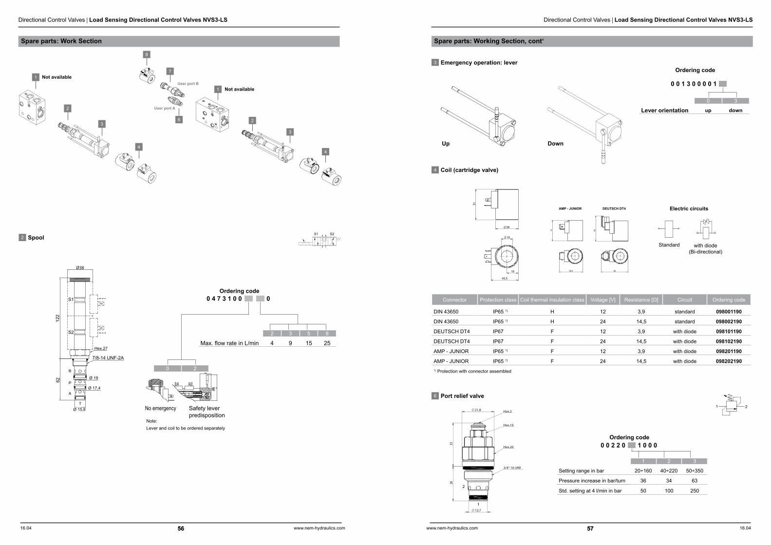
4 Coil (cartridge valve)
Connector Protection class Coil thermal insulation class Voltage [V] Resistance [Ω] Circuit Ordering code
DIN 43650 IP65 1) H 12 3,9 standard 098001190
DIN 43650 IP65 1) H 24 14,5 standard 098002190
DEUTSCH DT4 IP67 F 12 3,9 with diode 098101190
DEUTSCH DT4 IP67 F 24 14,5 with diode 098102190
AMP - JUNIOR IP65 1) F 12 3,9 with diode 098201190
AMP - JUNIOR IP65 1) F 24 14,5 with diode 0982021901) Protection with connector assembled
63
66
51
58,5
DEUTSCH DT4AMP - JUNIOR
51
38
19
45,5
19
with diode(Bi-directional)
Electric circuits
Standard
6 Port relief valve
12,7
26
33
21,8
3/4"-16 UNF
Hex.10
Hex.3
Hex.20
2
1
0 0 2 2 0 1 0 0 0 Ordering code
1 2 3
Setting range in bar 20÷160 40÷220 50÷350
Pressure increase in bar/turn 36 34 63
Std. setting at 4 l/min in bar 50 100 250
1 2
Ordering code3 Emergency operation: lever
0 0 1 3 0 0 0 0 1
0 3
Lever orientation up down
Up Down
Spare parts: Working Section, cont‘Spare parts: Work Section
2
1
3
4
2
1
3
4
User port A
User port B
2 SpoolS2S1
Note:Lever and coil to be ordered separately
0 4 7 3 1 0 0 0
No emergency Safety leverpredisposition
0 2
2 3 5 8
Max. flow rate in L/min 4 9 15 25
Ordering code
T
B
P
A
Ø 19
122
62
Ø 17,4P
B
S2
S1
7/8-14 UNF-2A
Hex.27
Ø 15,8
A
T
Ø38
Not available
Not available
6
7
8
16.04 16.04www.nem-hydraulics.com www.nem-hydraulics.com58 59
Directional Control Valves
59
Directional Control Valves | Load Sensing Directional Control Valves NVS3-LS
58
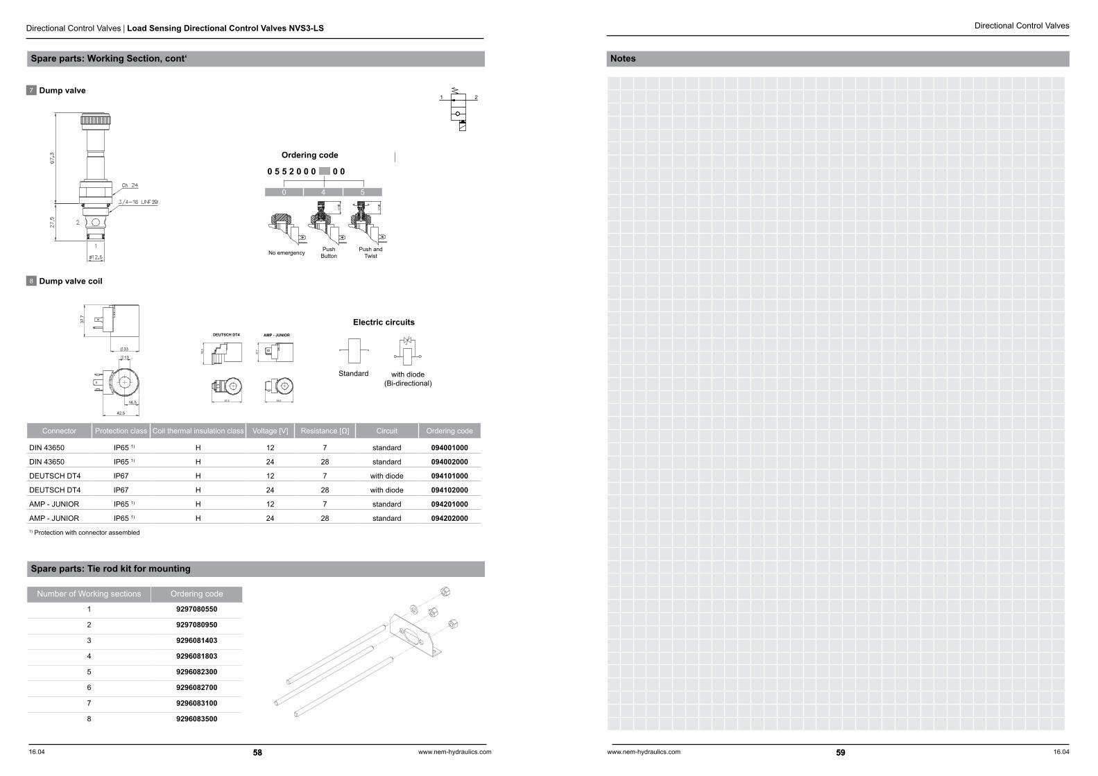
NotesSpare parts: Working Section, cont‘
Ordering code
0 5 5 2 0 0 0 0 0
No emergency Push Button
Push andTwist
7 Dump valve
8 Dump valve coil
Connector Protection class Coil thermal insulation class Voltage [V] Resistance [Ω] Circuit Ordering code
DIN 43650 IP65 1) H 12 7 standard 094001000
DIN 43650 IP65 1) H 24 28 standard 094002000
DEUTSCH DT4 IP67 H 12 7 with diode 094101000
DEUTSCH DT4 IP67 H 24 28 with diode 094102000
AMP - JUNIOR IP65 1) H 12 7 standard 094201000
AMP - JUNIOR IP65 1) H 24 28 standard 0942020001) Protection with connector assembled
37,7
55,5
42,5
57,5
DEUTSCH DT4 AMP - JUNIOR
37,7
33
13
42,5
16,5
0 4 5
1 2
with diode(Bi-directional)
Electric circuits
Standard
Number of Working sections Ordering code
1 9297080550
2 9297080950
3 9296081403
4 9296081803
5 9296082300
6 9296082700
7 9296083100
8 9296083500
Spare parts: Tie rod kit for mounting

DT0
04G
B00
0 IR
1 04
.201
6
NEM S.r.l. | Via F. Turati, 41/A | 42020 Quattro Castella (RE), Loc. Roncolo | Italy
Phone: +39 (0)522 25 87 11 | Fax: +39 (0)522 88 79 88
E-Mail: [email protected] | www.nem-hydraulics.com
All rights reserved -
subject to revision
Products ...... for mobile hydraulic applications
Mechanical and Electric Cartridge ValvesPressure control valves pmax 350 barCounter balance valves Qmax 200 L/minDirectional control valves Ports up to SAE 16Flow control valves M27x1,5
Hydraulic Integrated CircuitsWeight lifting pmax 350 barEarth moving Qmax 200 L/minAgricultural vehicles Industrial vehicles
Directional Control ValvesFlow sensing pmax 350 barLoad sensing Qmax 40 L/min Ports BSP 3/8“
Parts-in-Body ValvesCounter balance valves pmax 410 barPO check valves Qmax 500 L/minBoom lowering control valves Ports up to 11/4 SAE6000Pressure control valvesFlow control valves