DIRECT VENT SPECTRA SERIES - Inglenook Energy installation manual will help you obtain a safe,...
32
INSTALLATION INSTRUCTIONS VENTED GAS FIREPLACE HEATERS - DIRECT VENT MODELS P/N 850,016M REV. H 08/2007 FOR YOUR SAFETY: Do not store or use gasoline or other flammable vapors or liquids in the vicin- ity of this or any other appliance. FOR YOUR SAFETY: What to do if you smell gas: • DO NOT light any appliance. • DO NOT touch any electrical switches. • DO NOT use any phone in your building. • Immediately call your gas supplier from a neighbor’s phone. Follow your gas suppliers instructions. • If your gas supplier cannot be reached, call the fire department. Installation and service must be performed by a qualified installer, service agency or the gas supplier. MODELS POUR VOTRE SÉCURITÉ: Ne pas entreposer ni utiliser d'essence ni d'autre vapeurs ou liquides inflammables dans le voisinage de cet appareil ou de tout autre appareil. POUR VOTRE SÉCURITÉ: Que faire si vous sentez une odeur de gaz: • Ne pas tenter d'allumer d'appareil. • Ne touchez à aucun interrupteur. Ne pas vous servir des téléphones se trouvant dans le batiment où vous vous trouvez. • Evacuez la piéce, le bâtiment ou la zone. • Appelez immédiatement votre fournisseur de gaz depuis un voisin. Suivez les instructions du fournisseur. • Si vous ne pouvez rejoindre le fournisseur de gaz, appelez le service dos incendies. L'installation et service doit être exécuté par un qualifié installeur, agence de service ou le fournisseur de gaz. DIRECT VENT SPECTRA SERIES This appliance may be installed in an aftermar- ket permanently located, manufactured home (USA only) or mobile home, where not prohib- ited by local codes. This appliance is only for use with the type of gas indicated on the rating plate. This appliance is not convertible for use with other gases, unless a certified kit is used. LENNOX HEARTH PRODUCTS OTL Report No. 116-F-02-05 LSS-35CN LSS-40CN LSS-35CP LSS-40CP WARNING: IF THE INFORMATION IN THIS MANUAL IS NOT FOLLOWED EXACTLY, A FIRE OR EXPLO- SION MAY RESULT CAUSING PROPERTY DAM- AGE, PERSONAL INJURY OR LOSS OF LIFE. AVERTISSEMENT: ASSUREZ-VOUS DE BIEN SUIVRE LES INSTRUCTIONS DONNÉ DANS CETTE NOTICE POUR RÉDUIRE AU MINIMUM LE RISQUE D'INCENDIE OU POUR ÉVITER TOUT DOMMAGE MATÉRIEL, TOUTE BLESSURE OU LA MORT. A French manual is available upon request. Order Form Number 850,016CF. Ce manuel d’installation est disponible en francais, simplement en faire la demande. Numéro de la pièce 850,016CF. INSTALLER: Leave this manual with the appliance. CONSUMER: Retain this manual for future reference.
Transcript of DIRECT VENT SPECTRA SERIES - Inglenook Energy installation manual will help you obtain a safe,...

1NOTE: DIAGRAMS & ILLUSTRATIONS NOT TO SCALE.
INSTALLATIONINSTRUCTIONS
VENTED GAS FIREPLACE HEATERS - DIRECT VENT MODELSP/N 850,016M REV. H 08/2007
FOR YOUR SAFETY: Do not store or use gasolineor other flammable vapors or liquids in the vicin-ity of this or any other appliance.
FOR YOUR SAFETY: What to do if you smell gas:
• DO NOT light any appliance.• DO NOT touch any electrical switches.• DO NOT use any phone in your building.• Immediately call your gas supplier from a
neighbor’s phone. Follow your gas suppliersinstructions.
• If your gas supplier cannot be reached, call thefire department.
Installation and service must be performed by aqualified installer, service agency or the gassupplier.
MODELS
POUR VOTRE SÉCURITÉ: Ne pas entreposer ni utiliserd'essence ni d'autre vapeurs ou liquides inflammablesdans le voisinage de cet appareil ou de tout autreappareil.
POUR VOTRE SÉCURITÉ: Que faire si vous sentez uneodeur de gaz:
• Ne pas tenter d'allumer d'appareil.• Ne touchez à aucun interrupteur. Ne pas vous servir
des téléphones se trouvant dans le batiment oùvous vous trouvez.
• Evacuez la piéce, le bâtiment ou la zone.• Appelez immédiatement votre fournisseur de gaz
depuis un voisin. Suivez les instructions dufournisseur.
• Si vous ne pouvez rejoindre le fournisseur de gaz,appelez le service dos incendies.
L'installation et service doit être exécuté par un qualifiéinstalleur, agence de service ou le fournisseur de gaz.
DIRECT VENTSPECTRA SERIES
This appliance may be installed in an aftermar-ket permanently located, manufactured home(USA only) or mobile home, where not prohib-ited by local codes. This appliance is only foruse with the type of gas indicated on the ratingplate. This appliance is not convertible for usewith other gases, unless a certified kit is used.
LENNOX HEARTH PRODUCTS
OTL Report No. 116-F-02-05
LSS-35CN LSS-40CNLSS-35CP LSS-40CP
WARNING: IF THE INFORMATION IN THIS MANUALIS NOT FOLLOWED EXACTLY, A FIRE OR EXPLO-SION MAY RESULT CAUSING PROPERTY DAM-AGE, PERSONAL INJURY OR LOSS OF LIFE.
AVERTISSEMENT: ASSUREZ-VOUS DE BIEN SUIVRELES INSTRUCTIONS DONNÉ DANS CETTE NOTICE POURRÉDUIRE AU MINIMUM LE RISQUE D'INCENDIE OUPOUR ÉVITER TOUT DOMMAGE MATÉRIEL, TOUTEBLESSURE OU LA MORT.
A French manual is available upon request. Order Form Number850,016CF.
Ce manuel d’installation est disponible en francais, simplement enfaire la demande. Numéro de la pièce 850,016CF.
INSTALLER: Leave this manual with the appliance.CONSUMER: Retain this manual for future reference.

2 NOTE: DIAGRAMS & ILLUSTRATIONS NOT TO SCALE.
TABLE OF CONTENTS
Packaging ........................................ page 2
Introduction ..................................... page 2
General Information ......................... page 2
Location .......................................... page 3
Appliance and Vent Clearances ....... page 4
Framing Specifications .................... page 5
Facing Requirements ....................... page 6
Hearth Requirements ....................... page 7
Fireplace Specifications ................... page 8
Vent Termination Clearances ........... page 9
Typical Installation Sequence .......... page 9
Detailed Installation Steps ............... page 9
Step 1. Framing ............................. page 9
Step 2. Routing Gas Line ............... page 11
Step 3. Install the Venting System . page 11
Vertical Termination Systems .......... page 11
Vent Section Length Chart ............... page 12
Vertical Vent Tables and Figures ...... page 15
Horizontal Termination System ........ page 16
Horizontal Vent Tables and Figures . page 18
Venting Using Flexible Vent Pipe ..... page 20
Step 4. Field Wiring ....................... page 21
Step 5. Connecting Gas Line .......... page 21
Comfort Control Valve ..................... page 22
Step 6. Installing Ceramic Panels
And Logs ..................................... page 24
Step 7. Checking Unit Operation ..... page 24
Step 8. Installing Glass Door ......... page 24
Step 9. Burner Adjustments ........... page 25
Finishing Requirements ................... page 26
Cold Climate Insulation .................... page 26
Installation Accessories ................... page 27
Gas Conversion Kits .................. page 28
DO NOT ATTEMPT TO ALTER OR MODIFYTHE CONSTRUCTION OF THE APPLIANCE ORITS COMPONENTS. ANY MODIFICATION ORALTERATION MAY VOID THE WARRANTY,CERTIFICATION AND LISTINGS OF THIS UNIT.
INTRODUCTION
These fireplaces are designed, tested and listedfor operation and installation with, and only with,Secure Vent™ Direct Vent System Components,Secure Flex™ Flexible Vent Components manu-factured by Security Chimneys International andZ-Flex™ Model GA Venting Systems, listed toUL1777 and ULCS635 manufactured by Flex-master Canada Limited. These approved ventsystem components are labeled for identifica-tion. DO NOT use any other manufacturer's ventcomponents with these appliances.
These appliances comply with National SafetyStandards and are tested and listed by Omni-Test Laboratories (Report No. 116-F-02-5) toANSI Z21.88 (in Canada, CSA-2.33), and CAN/CGA-2.17-M91 in both USA and Canada, asvented gas fireplace heaters.
PACKAGING
The assembled Spectra direct vent gas fire-place heater is packaged with:
1 - one log set located in firebox area.2 - one envelope containing the literature
package which consists of the homeowner'smanual, installation instructions, log setsupplement and warranty; envelope is lo-cated in the control area.
3 - one bag of glowing embers located in thecontrol area.
4 - one ceramic panel set, located on top ofunit.
5 - one hand held remote control, located inthe control area.
6 - an additional one of the following itemsrequired:1: Cast Iron Face (Classic Arch) and Grillwork (Black, Gold or Nickel) or2: Arched Face (Black, Gold or Nickel) or3: Rectangular Face (Black, Gold or Brushed Stainless)
Each kit comes with an individual set ofinstallation instructions.
Note: Installation and repair should be per-formed by a qualified service person. The appli-ance should be inspected annually by a quali-fied professional service technician. More fre-quent inspections and cleanings may be re-quired due to excessive lint from carpeting,bedding material, etc. It is imperative that thecontrol compartment, burners and circulatingair passage ways of the appliance be kept clean.
S'assurer que le brùleur et le compartimentdes commandes sont propres. Voir les in-structions d'installation et d'utilisation quiaccompagnent l'appareil.
Provide adequate clearances around air open-ings and adequate accessibility clearance forservice and proper operation. Never obstructthe front openings of the appliance.
Please read and understand theseinstructions before beginning your
installation.
GENERAL INFORMATION
Note: For combustible material refer toFigure 48 on page 26.
These appliances are designed to operate onnatural or propane gas only.
This installation manual will help you obtain asafe, efficient, dependable installation for yourappliance and vent system.
The Installation must conform to local codesor, in the absence of local codes, with theNational Fuel Gas Code, ANSI Z223.1/NFPA54, or the Natural Gas and Propane Installa-tion Code, CSA B149.1. The appliance, wheninstalled, must be electrically grounded inaccordance with local codes or, in the ab-sence of local codes, with the National Elec-trical Code, ANSI/NFPA 70, or the CanadianElectrical Code, CSA C22.1.
These appliances are listed by Omni-TestLaboratories for installation in bedrooms andmobile homes.
WARNING: 1) FIRE HAZARD: DO NOTPLACE ANY COMBUSTIBLE MATERIALOVER THE FIREPLACE OPENING. 2) DOORFRONT ACCESSIBILITY: ANY NON-COM-BUSTIBLE FINISHING MATERIAL AREASTHAT PROTRUDE MORE THAN 1" FROMTHE FACING SHOULD MAINTAIN A 9"CLEARANCE TO THE FIREPLACE OPEN-ING. SEE FIGURE 7, PAGE 6 FOR DETAILS.

3NOTE: DIAGRAMS & ILLUSTRATIONS NOT TO SCALE.
Test gage connections are provided on thefront of the gas control valve (identified INfor the inlet and OUT for the manifold side).
Do not use these appliances if any part hasbeen under water. Immediately call a quali-fied, professional service technician to inspectthe appliance and to replace any parts of thecontrol system and any gas control whichhave been under water.
Ne pas se servir de cet appareil s'il a été plongédans l'eau, complètement ou en partie. Appelerun technicien qualifié pour inspecter l'appareil etremplacer toute partie du système de contrôle ettoute commande qui ont été plongés dans l'eau.
These appliances feature a comfort controlvalve which allows remote control of tem-perature, fan and flame appearance. Theseappliances also use a spark ignitor (piezo)that allows the appliance's pilot gas to be litwithout the use of matches. This systemprovides continued service in the event of apower outage.
These appliances must not be connected to achimney or flue serving a separate solid fuelburning appliance.
Carbon Monoxide Poisoning: Early signs ofcarbon monoxide poisoning are similar tothe flu with headaches, dizziness and/ornausea. If you have these signs, obtainfresh air immediately. Turn off the gas sup-ply to the appliance and have it serviced bya qualified professional, as it may not beoperating correctly.
LOCATION
In selecting the location, the aesthetic and func-tional use of the appliance are primary concerns.However, vent system routing to the exterior andaccess to the fuel supply are also important.Consideration should be given to traffic ways,furniture, draperies, etc., due to elevated surfacetemperatures (see Figure 2 ).
Figure 1
TYPICAL INSTALLATION
Table 1
Installations at Altitudes of 0 to 4500 ft.-Units are tested and approved for elevationsof 0 to 4500 feet (0 to 1372 meters).
Installations at Altitudes above 4500 ft.-For elevations above 4500 feet (1372meters), install the unit according to theregulations of the local authorities havingjurisdiction and, in the USA, the latestedition of the National Fuel Gas Code (ANSIZ223.1) or, in Canada, the latest edition ofthe CAN1-B149.1 and .2 codes.
Gas Inlet And Manifold Pressures
Gas Specifications
Table 1 shows the units' gas orifice size forthe elevations indicated.
ledoM leuF raeRrenruB
tnorFrenruB
NC53-SSL saG.taN 44# 05#
PC53-SSL saGPL 55# 16#
NC04-SSL saG.taN 24# 54#
PC04-SSL saGPL "450.0 65#
These appliances must be isolated from the gassupply piping system (by closing their individualmanual shut-off valve) during any pressure test-ing of the gas supply piping system at test pres-sures equal to or less than 1/2 psig (3.5 kPa).
These appliances and their individual shut-offvalves must be disconnected from the gassupply piping system during any pressuretesting of that system at pressures in excess of1/2 psig (3.5 kPa).
ledoM leuFmumixaM
tupnI)H/UTB(
muminiMtupnI
)H/UTB(
NC53-SSL saG.taN 000,33 005,32
PC53-SSL saGPL 000,13 005,32
NC04-SSL saG.taN 005,14 004,82
PC04-SSL saGPL 000,93 007,03
larutaN )enaporP(PLmuminiM
erusserPtelnI .c.w"0.5 .c.w"0.11
mumixaMerusserPtelnI .c.w"0.41 .c.w"0.41
dlofinaMerusserP .c.w"5.3 .c.w"0.01
The external electrical power (120V) is re-quired to operate the provided circulatingblower.
Drywall
Mantel
Non-Combustible
Top OfFireplace Opening
WARNING: FAILURE TO COMPLY WITHTHE INSTALLATION AND OPERATING IN-STRUCTIONS PROVIDED IN THIS DOCU-MENT WILL RESULT IN AN IMPROP-ERLY INSTALLED AND OPERATING AP-PLIANCE, VOIDING ITS WARRANTY. ANYCHANGE TO THIS APPLIANCE AND/ORITS OPERATING CONTROLS IS DANGER-OUS. IMPROPER INSTALLATION OR USEOF THIS APPLIANCE CAN CAUSE SERI-OUS INJURY OR DEATH FROM FIRE,BURNS, EXPLOSION OR CARBON MON-OXIDE POISONING.
WARNING: CHILDREN AND ADULTSSHOULD BE ALERTED TO THE HAZARDSOF HIGH SURFACE TEMPERATURES. USECAUTION AROUND THE APPLIANCE TOAVOID BURNS OR CLOTHING IGNITION.YOUNG CHILDREN SHOULD BE CARE-FULLY SUPERVISED WHEN THEY ARE INTHE SAME ROOM AS THE APPLIANCE.
WARNING: DO NOT PLACE CLOTHINGOR OTHER FLAMMABLE MATERIALSON OR NEAR THIS APPLIANCE.
AVERTISSEMENT: SURVEILLER LESENFANTS. GARDER LES VÊTEMENTS,LES MEUBLES, L'ESSENCE OU AUTRESLIQUIDES À VAPEUR INFLAMMABLESÀ COTE DE L'APPAREIL.

4 NOTE: DIAGRAMS & ILLUSTRATIONS NOT TO SCALE.
.oNledoM)mm(sehcnithgieHflehS
woblEeergeD09enOhtiw-tneVpoT
tneVeruceS xelFeruceS53-SSL 2/175 )1641( 4/195 )5051(04-SSL )9941(95 )3451(4/306
Shelf Height(see table)
Do not insulate thespace between theappliance and the
area above it.
Shelf Above Fireplace With Top Venting
12 ¹⁄₄”(311mm)
*Note: For Secure Vent A SV4.5L6 6” Section (Cat. No. 77L70) Is Required.
*See Note
Figure 2
Figure 3
HORIZONTAL VENT VERTICAL VENT
TOP VENT APPLICATIONS
*Note: 3 in. (75 mm) above any horizontal/inclined vent component.
Note: The nailing flange and the cabinetsurfaces directly adjacent to the framingmember attached to the nailing flange, areexempt from the 1/2" clearance to combus-tibles defined for the rest of the cabinetsides and back.
Table 2
KCAB )mm31(.ni2/1srecaps)mm0(.ni0
SEDIS )mm31(.ni2/1srecaps)mm0(.ni0
SRECAPSPOT )mm0(.ni0
ROOLF )mm0(.ni0
fomottoBmorFgnilieCottinU )mm6261(.ni46
TNEV *)mm4.52(.ni1
SECNARAELCECIVRES
TNORF )sretem9.0(.teeF3
Typical Locations
The location should also be free of electrical,plumbing or other heating/air conditioning duct-ing. These direct vent appliances are uniquelysuited for installations requiring a utility shelfpositioned directly above the fireplace. Utilityshelves like these are commonly used for locat-ing television sets and decorative plants.
Do not insulate the space between the appli-ance and the area above it. See Figure 3. Theminimum height from the base of the applianceto the underside of combustible materials usedto construct a utility shelf in this fashion is shownin the table in Figure 3.
The appliance should be mounted on a fullysupported base extending the full width anddepth of the unit. The appliance may be locatedon or near conventional construction materi-als. However, if installed on combustible ma-terials, such as carpeting, vinyl tile, etc., ametal or wood barrier covering the entire bot-tom surface must be used.
APPLIANCE AND VENT CLEARANCES
These appliances are approved with zero clear-ance from spacers to combustible materials onall sides (as detailed in Table 2 ), with thefollowing exception: When the unit is installedwith one side flush with a perpendictular sidewall, the wall perpendicular to the opposite sideof the appliance front face must not extendmore than five inches beyond the front edge ofthe unit. In addition, when the unit is recessed,the side walls surrounding the unit must notextend more than five inches beyond the frontedge of the unit. Refer to Figure 2.

5NOTE: DIAGRAMS & ILLUSTRATIONS NOT TO SCALE.
Figure 4
Figure 5 Corner Framing with Square Termination (SV4.5HT)
Framing Dimensions
FIREPLACE FRAMING SPECIFICATIONS
A
B
7(178)
(308)
(267)
C
VENT FRAMING -TOP VENT WITH ONE
6” SECTION ANDONE 90° ELBOW
Framing should be constructedof 2x4 or larger lumber.
Inches (mm)
(130)
**FRAMING WITH SQUARE HORIZONTAL TERMINATIONS (SV4.5HT)
** See the horizontal venting Figures 29 and 30 on page 17 forrestrictions on the use of the square termination (SV4.5HT).
NOTE: For Secure Vent A 6” SectionSV4.5L6 (Cat. No. 77L70) Is RequiredBefore Installing The 90 Degree Elbow.
5-1/8
12-1/8
10-1/2
20-13/161/2 A
ledoM.oN A B C D E
53-SSL.ni 53 8/1 61/526 8/193 8/163 61/1151mm 298 3851 499 819 004
04-SSL .ni 8/104 61/576 8/574 8/583 61/771mm 2201 0171 0121 189 344
C
Back wall of chase/enclosure(including any finishing materials)
Note-Venting requirements for corner installations -
D
A
B
E
ledoM.oN A B C
53-SSL.ni 53 8/1 8/524 8/115mm 298 3801 9921
04-SSL .ni 8/104 8/144 8/525mm 2201 1211 7331

6 NOTE: DIAGRAMS & ILLUSTRATIONS NOT TO SCALE.
FACING REQUIREMENTS
Figure 6
Figure 7 Non-Combustible Requirements
Unit Nailing Flange (On Both Sides)
Fireplace
TOP VIEW
1/2” Drywall
Faceplate
3/8” Tile
1/2” Concrete Board
2” x 4”
9”Min.
Requires A Concrete Board(Or Other Non-Combustible
Material) Extending FromThe Top Of The Fireplace To
The Floor And To TheFraming Members On Both
Sides. Do Not UseSheetrock, Plywood Or Other
Combustible Material
4 1/2” Min.(Both Sides)
Top Of Fireplace Non-Combustible Material
Warning: 1) Fire Hazard: Do NotPlace Any Combustible MaterialOver The Fireplace Opening. 2) DoorFront Accessibility: Any Non-Combustible Finishing MaterialAreas That Protrude More Than 1”From The Facing Must Maintain A 9”Clearance To The Fireplace Opening. For Combustible Material, Refer ToFigure 48 On Page 26.
Top Of Fireplace Opening
10”

7NOTE: DIAGRAMS & ILLUSTRATIONS NOT TO SCALE.
HEARTH REQUIREMENTS
Figure 8
Cement Board
Tile, Marble, Brick, Carpet,Or Other Non-CombustibleOr Combustible Material
FireplaceStand
1”Min.
Figure 9 RAISED FIREPLACE
Fireplace
Floor Plywood Platform
Face
Thickness Of the Floor Covering(Carpet, Flooring, Etc.)
1” Min.

8 NOTE: DIAGRAMS & ILLUSTRATIONS NOT TO SCALE.
Figure 10
FIREPLACE SPECIFICATIONS
H
ELECTRICALINLET
Diminsions In Inches (mm)
* Includes The 1/2” Spacers
1 (25.4)
3 (76)
11 ¹⁄₄(286)
G
1/2” Spacers
8 ¹¹⁄₃₂(211)
A E
D
F
B
C
1(25.4)
3 (76)
GAS INLET(BOTH SIDES)
*21 ³⁄₈(543)
6(152)
8 ¹³⁄₁₆(225)
2 ⁹⁄₁₆(65)
3(76)
FRAMING SPACERS
CONCENTRIC FLUECombustion Air - 7 ¹⁄₂ (190)Flue - 4 ¹⁄₂ (114)
3 (76)
Vent RestrictorAdjustment Rod
ledoM.oN A B C D E F G H
53-SSL.ni 8/383 61/153 2/192 91 61/361 8/313 2/112 4/301mm 579 198 947 384 114 797 645 372
04-SSL .ni 8/793 61/104 2/143 2/102 61/312 8/723 2/162 4/131mm 3101 8101 678 125 835 538 376 733

9NOTE: DIAGRAMS & ILLUSTRATIONS NOT TO SCALE.
hctiPfooR )teef(H21/6ottalF 0.1
21/7ot21/6revO 52.121/8ot21/7revO 5.121/9ot21/8revO 0.221/01ot21/9revO 5.221/11ot21/01revO 52.3
ot21/11revO21/21 0.4
12X
Roof Pitch is X/12
2 FTMIN.2 FT MIN.Lowest
DischargeOpening
H*
*H = MINIMUM HEIGHT FROM ROOF TOLOWEST DISCHARGE OPENING OF VENT
TERMINATION HEIGHTS FOR VENTS ABOVEFLAT OR SLOPED ROOFS
Horizontal Overhang
VerticalWall
VentTermination
Storm Collar
ConcentricVent Pipe
Flashing
1 inch (25.4 mm) MinimumClearance to Combustibles
Figure 11
Figure 12 - Side Elevation View
3"(76 mm)
12"(305 mm)
Termination Kit
Combustible Projectiongreater than inches in length
Combustible Projection2-1/2 inches or less in length
18"(457 mm)
VentilatedSoffit Unventilated
Soffit
Horizontal Vent Termination Clearances
2-1/2
Termination Kit
All horizontal terminationsmay be located as close
as 6” (152mm) to any(non-combustible andcombustible) exterior
sidewall. This distancemay be decreased to
2” (51mm) for non-combustible exteriorsidewalls only, if the
SV4.5HT-2 terminationis used.
Horizontal Vent Termination ClearancesThe horizontal vent termination must have aminimum of 3" (76 mm) clearance to anyoverhead combustible projection of 2-1/2" (64mm) or less. See Figure 5. For projectionsexceeding 2-1/2" (64 mm), see Figure 5. Allhorizontal terminations may be located asclose as 6" (152mm) to any (non-combustibleand combustible) exterior sidewall. This dis-tance may be decreased to 2" (51mm) for non-combustible exterior sidewalls only, if theSV4.5HT-2 termination is used. For projec-tions exceeding 2 ¹⁄₂" (64 mm), see Figure 12.
Terminate multiple vent terminations accord-ing to the installation codes listed at the top ofthis page.
Vertical Vent Termination Clearances
VENT TERMINATION CLEARANCES
These instructions should be used as a guide-line and do not supersede local codes in anyway. Install vent according to local codes,these instructions, the current National FuelGas Code (ANSI-Z223.1) in the USA or thecurrent standards of CAN/CGA-B149.1 and -B149.2 in Canada.
Terminate single vent caps relative to buildingcomponents according to Figure 11.
TYPICAL INSTALLATION SEQUENCE
The typical sequence of installation follows,however, each installation is unique resulting invariations to those described.
See the page numbers references in the follow-ing steps for detailed procedures.
Step 1. (page 9) Construct the appliance fram-ing. Position the appliance within the framingand secure with nailing brackets.Step 2. (page 11) Route gas supply line toappliance location.Step 3. (page 11) Install the vent system andexterior termination.Step 4. (page 21) Field WiringInstall the operating control switch (not factoryprovided) and bring in electrical service line forforced air circulating blower.Step 5. (page 21) Make connection to gas supply.Step 6. (page 24) Install the ceramic panel, logs,and glowing embers.Step 7. (page 24) Checkout appliance operation.Step 8. (page 25) Install glass door frame assembly.Step 9. (page 25) Adjust burner to ensureproper flame appearance.
DETAILED INSTALLATION STEPS
The appliance is shipped with all gas controlsand components installed and pre-wired. Re-move the shipping carton, exposing the frontglass door. Remove ceramic panel kit from thetop of the fireplace and set it aside with care.Remove the cardboard from underneath thepressure relief plates. Open the two latches(located under the firebox floor) securing theglass door. Remove the door by tilting it out-ward at the bottom and lifting it up. Set the dooraside protecting it from inadvertent damage.See Figure 46 on page 25.
Step 1. FRAMING
Frame these appliances as illustrated inFigure 4 on page 5, unless the appliance isto be installed in a corner. See Figure 5 onpage 5 for corner framing installations. Allframing details must allow for a minimumclearance to combustible framing mem-bers as shown in Table 2 on page 4. SeeFigure 6 on page 6 for the facing detail.
See Figure 7 on page 6 for the Non-Combus-tible requirements. See Figures 8 and 9 onpage 7 for Hearth Requirements.

10 NOTE: DIAGRAMS & ILLUSTRATIONS NOT TO SCALE.
Figure 14
EXTERIOR HORIZONTAL VENT TERMINATION CLEARANCE REQUIREMENTS
V
VV
V
V
F
C
FixedClosed
Window
OperableWindow
B
B
A
B
H
M
I
= Vent Terminal = Area where Terminal is not Permitted= Air Supply InletX V
D
V
3 ft.
3 ft.
A A
A = 9” in U.S.= 12” in Canada
VL
B
J
X E
V
A
G
InsideCorner Detail
*18”
Ventilated Soffit
HorizontalTermination
Detail D
Exterior Wall Center Lineof Termination
18”
Inside Corner
BC
C
C
* See Item D in the Text Below.
*noitallatsnInaidanaC **noitallatsnISU,hcrop,adnarev,edargevobaecnaraelC=A
.ynoclabro,kced*)mc03(sehcni21 **)mc03(sehcni21
ebyamtahtroodrowodniwotecnaraelC=B.denepo
secnailpparof)mc51(ni6)mc03(ni21,)Wk3(hutB000,01<
dna)Wk3(hutB000,01>secnailpparof)mc19(sehcni63,)Wk03(hutB000,001<
*)Wk03(hutB000,001>secnailpparof
secnailpparof)mc51(ni6)mc32(ni9,)Wk3(hutB000,01<
dna)Wk3(hutB000,01>secnailpparof)mc03(sehcni21,)Wk51(hutB000,05<
**)Wk51(hutB000,05>secnailpparofwodniwdesolcyltnenamrepotecnaraelC=C tneverpotdednemmocer)mm503("21
noitasnednocwodniwtneverpotdednemmocer)mm922("9
noitasnednocwodniw
tiffosdetalitnevotecnaraelclacitreV=Dlatnozirohanihtiwlanimretehtevobadetacolretnecehtmorf)mm854(sehcni81foecnatsid
lanimretehtfoenil
)mm854("81 )mm854("81
tiffosdetalitnevnuotecnaraelC=E )mm503("21 )mm503("21renrocedistuootecnaraelC=F muminim)mc7.21("5 muminim)mc7.21("5
renrocedisniotecnaraelC=G •2-TH5.4VS-muminim)mc80.5("2SSTH5.4VS-muminim)mc2.51("6
•2-TH5.4VS-muminim)mc80.5("2SSTH5.4VS-muminim)mc2.51("6
enilretnecfoedisnihcaeotecnaraelC=Hylbmessarotaluger/retemevobadednetxe
teef51fothgiehanihtiw)mc19(teef3*ylbmessarotaluger/retemehtevoba
teef51fothgiehanihtiw)mc19(teef3**ylbmessarotaluger/retemehtevoba
teltuotnevrotalugerecivresotecnaraelC=I *)mc19(teef3 **)mc19(teef3telniylppusrialacinahcemnonotecnaraelC=J
ynaottelnirianoitsubmocehtrognidliubotecnailpparehto
secnailpparof)mc51(ni6)mc03(ni21,)Wk3(hutB000,01<
dna)Wk3(hutB000,01>secnailpparof)mc19(sehcni63,)Wk03(hutB000,001<
*)Wk03(hutB000,001>secnailpparof
secnailpparof)mc51(ni6)mc32(ni9,)Wk3(hutB000,01<
dna)Wk3(hutB000,01>secnailpparof)mc03(sehcni21,)Wk51(hutB000,05<
**)Wk51(hutB000,05>secnailpparoftelniylppusrialacinahcemaotecnaraelC=K *)m38.1(teef6 )m3(teef01nihtiwfievoba)mc19(teef3
**yllatnozirohdevaproklawedisdevapevobaecnaraelC=L
ytreporpcilbupnodetacolyawevid‡)m31.2(teef7 ‡)m31.2(teef7
rokced,hcrop,adnarevrednuecnaraelC=Mynoclab
‡*)mc03(sehcni21 ‡)mc03(sehcni21
.edoCnoitallatsnIenaporPdnAsaGlanoitaN1.941B-ASCtnerrucehthtiwecnadroccanI*.sedoCsaGleuFlanoitaN45APFN/1.322ZSISNAtnerucehthtiwecnadroccanI**
sevresdnasgnillewdylimafelgnisowtneewtebdetacolsihcihwyawevirddevaproklawedisaevobayltceridetanimrettonllahstnevA‡.sgnillewdhtob
:roolfehthtaenebsedis2muminimanonepoyllufsiynoclabrokced,hcrop,adnarevfidettimrepylnO‡*.ylnO2-TH5.4VSrofselbitsubmoC-noNotecnaraelC"2•

11NOTE: DIAGRAMS & ILLUSTRATIONS NOT TO SCALE.
Right SideFront Corner of
Fireplace Framing
6"(152 mm)
3"(76 mm)
Figure 13
Step 3. INSTALL THE VENT SYSTEM
General Information
These instructions should be used as a guide-line and do not supersede local codes in anyway. Install vent according to local codes,these instructions, the current National FuelGas Code (ANSI-Z223.1) in the USA or thecurrent standards of CAN/CGA-B149.1 and -B149.2 in Canada.
These fireplaces are designed, testedand listed for operation and installationwith, and only with, Secure Vent™ DirectVent System Components, Secure Flex™Flexible Vent Components manufacturedby Security Chimneys International andZ-FLEX™ Model GA Venting Systems listedto UL1777 and ULCS635 manufactured byFlexmaster Canada Limited.
These approved vent system componentsare labeled for identification. DO NOTuse any other manufacturer's ventcomponents with these appliances.
Some local jurisdictions may require the gapbetween the outer wall of the vent systemand the firestop penetration opening to besealed. This is not a requirement of thelisting of this product, however this gap maybe sealed using aluminized tape or similarnon-combustible material.
The vent system may not service multiple appli-ances, and must never be connected to a flueserving a solid fuel burning appliance. The ventpipe is tested to be run inside an enclosing wall(such as a chase). There is no requirement forinspection openings in the enclosing wall at anyof the joints in the vent pipe.
Select Venting System - Horizontal or Vertical
With the appliance secured in framing, deter-mine vent routing and identify the exteriortermination location. The following sectionsdescribe vertical (roof) and horizontal (exte-rior wall) vent applications. Refer to the sec-tion relating to your installation. A list ofapproved venting components is shown inthe two tables on page 27.
VERTICAL TERMINATION SYSTEMS (ROOF)
Figure 15, and Figures 25 through 27 onpages 12 and 15 and their associatedVertical Vent Tables illustrate the various verti-cal venting configurations that are possible foruse with these appliances. Secure Vent pipeapplications are shown in these figures; SecureFlex pipe may also be used. A Vertical VentTable summarizes each system’s minimumand maximum vertical and horizontal lengthvalues that can be used to design and install thevent components in a variety of applications.
Both these vertical vent systems terminatethrough the roof. The minimum vent heightabove the roof and/or adjacent walls is speci-fied in ANSI Z223.1-(latest edition) (In Canada,the current CAN-1 B149 installation code) bymajor building codes. Always consult yourlocal codes for specific requirements. A gen-eral guide to follow is the Gas Vent Rule (referto Figure 11 on page 9).
Massachusetts And New York City, NYRequirements
These appliances are approved for installationin the following USA locations listed in thefollowing:
Massachusetts:Installation of these fireplaces are approvedfor installation in the US state of Massachu-setts if the following additional requirementsare met-
• Installation and repair must be done by aplumber or gas fitter licensed in the Common-wealth of Massachusetts.• The flexible gas line connector used shall notexceed 36 inches (92 centimeters) in length.• The individual manual shut-off must be a T-handle type valve.
New York City, NY:Installation of these fireplaces are approvedfor installation in New Your City in the US stateof New York.
Massachusetts Horizontal Vent Requirements
In the Commonwealth of Massachusetts, hori-zontal terminations installed less than seven(7) feet above the finished grade must complywith the following additional requirements:
• A hard wired carbon monoxide detector withan alarm and battery back-up must be installedon the floor level where the gas fireplace isinstalled. The carbon monoxide detector mustcomply with NFPA 720, be ANSI/UL 2034listed and be ISA certified.
• A metal or plastic identification plate must bepermanently mounted to the exterior of thebuilding at a minimum height of eight (8) feetabove grade and be directly in line with thehorizontal termination. The sign must read, inprint size no less than one-half (1/2) inch insize, GAS VENT DIRECTLY BELOW. KEEPCLEAR OF ALL OBSTRUCTIONS.
These fireplaces must be vented directlyto the outside.
Step 2. ROUTING GAS LINE
Route a 1/2" (13 mm) gas line along the insideof the right side framing as shown in Figure 13.Gas lines must be routed, constructed andmade of materials that are in strict accordancewith local codes and regulations.
All appliances are factory-equipped with a flex-ible gas line connector and 1/2" inch shutoffvalve. (See step 5 on page 21).

12 NOTE: DIAGRAMS & ILLUSTRATIONS NOT TO SCALE.
Figure 15
Vertical (Offset) Installation
Analyze the vent routing and determine thequantities of vent sections and number ofelbows required. Refer to Vertical Vent Fig-ures and Tables on page 15 to select the typeof vertical installation desired. Vent sectionsare available in net lengths of 4-1/2" (114 mm),10-1/2" (267 mm), 22-1/2" (572 mm), 34-1/2"(876 mm) and 46-1/2" (1181 mm). Refer to theVent Section Length Chart on this page for anaid in selecting length combinations. Elbowsare available in 90° and 45° configurations.Refer to Figure 20 for the SV4.5E45 andSV4.5E90 elbow dimensional specifications.
TRAHCHTGNELNOITCESTNEVnoitceSlanimoN)sehcni(htgneL 6 21 42 63 84 T
OTAL
QTY
noitceSteN)sehcni(htgneL 2/1-4 2/1-01 2/1-22 2/1-43 2/1-64
tneVfothgieH snoitceStneVforebmuN
sehcni tf
441 21 1 0 0 0 3 4
051 5.21 0 1 0 0 3 4
5.451 578.21 1 1 0 0 3 5
5.061 573.31 0 2 0 0 3 5
5.271 573.41 0 0 0 5 0 5
771 57.41 1 0 0 5 0 6
381 52.51 0 1 0 5 0 6
681 5.51 0 0 0 0 4 4
5.091 578.51 1 0 0 0 4 5
5.691 573.61 0 1 0 0 4 5
5.502 521.71 0 1 1 5 0 7
702 52.71 0 0 0 6 0 6
5.112 526.71 1 0 0 6 0 7
5.712 521.81 0 1 0 6 0 7
5.922 521.91 0 0 1 6 0 7
5.232 573.91 0 0 0 0 5 5
732 57.91 1 0 0 0 5 6
5.142 521.02 0 0 0 7 0 7
642 5.02 1 0 0 7 0 8
252 12 0 1 0 7 0 8
462 22 0 0 1 7 0 8
672 32 0 0 0 8 0 8
972 52.32 0 0 0 0 6 6
5.082 573.32 1 0 0 8 0 9
5.382 526.32 1 0 0 0 6 7
5.982 521.42 0 1 0 0 6 7
5.103 521.52 0 0 1 0 6 7
5.013 578.52 0 0 0 9 0 9
513 5.62 1 0 0 9 0 01
5.523 521.72 0 0 0 0 7 7
033 5.72 1 0 0 0 7 8
633 82 0 1 0 0 7 8
543 57.82 0 0 0 01 0 01
5.943 521.92 1 0 0 01 0 11
273 13 0 0 0 0 8 8
5.673 573.13 1 0 0 0 8 9
5.973 526.13 0 0 0 11 0 11
5.814 578.43 0 0 0 0 9 9
324 52.53 1 0 0 0 9 01
564 57.83 0 0 0 0 01 01
TRAHCHTGNELNOITCESTNEVnoitceSlanimoN)sehcni(htgneL 6 21 42 63 84 T
OTAL
QTY
noitceSteN)sehcni(htgneL 2/1-4 2/1-01 2/1-22 2/1-43 2/1-64
tneVfothgieH snoitceStneVforebmuN
sehcni tf
5.4 573.0 1 0 0 0 0 1
9 57.0 2 0 0 0 0 2
5.01 578.0 0 1 0 0 0 1
51 52.1 1 1 0 0 0 2
5.91 526.1 2 1 0 0 0 3
12 57.1 0 2 0 0 0 2
5.22 578.1 0 0 1 0 0 1
5.52 521.2 1 2 0 0 0 3
5.13 526.2 0 3 0 0 0 3
5.43 578.2 0 0 0 1 0 1
5.73 521.3 1 1 1 0 0 3
5.34 526.3 0 2 1 0 0 3
54 57.3 0 0 2 0 0 2
5.64 578.3 0 0 0 0 1 1
5.94 521.4 1 0 2 0 0 3
15 52.4 1 0 0 0 1 2
5.55 526.4 0 1 2 0 0 3
75 57.4 0 0 1 1 0 2
66 52.5 0 2 2 0 0 4
5.76 526.5 0 0 3 0 0 3
96 57.5 0 0 0 2 0 2
27 6 1 0 3 0 0 4
5.37 521.6 1 0 0 2 0 3
5.97 526.6 0 1 0 2 0 3
18 57.6 0 0 0 1 1 2
09 5.7 0 2 1 0 1 4
5.19 526.7 0 0 2 0 1 3
39 57.7 0 0 0 0 2 2
69 8 1 0 1 2 0 4
5.79 521.8 1 0 0 0 2 3
201 5.8 2 0 0 0 2 45.301 526.8 0 0 0 3 0 3
801 9 1 0 0 3 0 4
411 5.9 0 2 0 0 2 4
711 57.9 1 0 5 0 0 6
5.811 578.9 1 1 0 3 0 5
621 5.01 0 0 1 3 0 4
5.031 578.01 1 0 1 3 0 5
531 52.11 0 0 6 0 0 6
831 5.11 0 0 0 4 0 4
5.931 526.11 0 0 0 0 3 3
5.241 578.11 1 0 0 4 0 5
Vertical (Straight) Installation
Determine the number of straight vent sec-tions required. 4-1/2" (114 mm), 10-1/2" (267mm), 22-1/2" (572 mm), 34-1/2" (876 mm)and 46-1/2" (1181 mm) net section lengths areavailable. Plan the vent lengths so that a jointdoes not occur at the intersection of ceiling orroof joists. Refer to the Vent Section LengthChart on this page.
SV4.5CGV-1Termination SV4.5FA OR
SV4.5FB FlashingAND SV4.5SCSTORM COLLAR
*SV4.5VFFirestop/Spacer
SV4.5L6/12/24/36/48Vent Sections
40' Max(12.2 M)
1" (25.4 mm)MinimumClearance toCombustibles
*When using Secure Flex,use Firestop/Spacer
SF4.5VF

13NOTE: DIAGRAMS & ILLUSTRATIONS NOT TO SCALE.
Figure 19
Support Straps(Plumber’s tape)
8 feet (2.4 m)Maximum
Blocking
Figure 18
Figure 17
Figure 16
B. Attach vent components to appliance -Secure Vent SV4.5 direct vent system compo-nents are unitized concentric pipe componentsfeaturing positive twist lock connections (seeFigure 17 ).
All of the appliances covered in this document arefitted with collars having locking inclined chan-nels. The dimpled end of the vent components fitover the appliance collar to create the positivetwist lock connection.
First VentComponentAlign the dimple (four places)with the opening of the lockingincline channel on appliancecollar. Twist vent componentclockwise to engage and seal.
LockingIncline Channel
Dimple
Appliance collar
Vent / Appliance CollarConnection
Align the dimple (four places) of theupper vent section with the opening ofthe locking incline channel on thelower vent section. Twist ventcomponent clockwise to engage andseal until arrow and dimple align.
LockingIncline Channel
Dimple
ArrowConnected
Vent Sections
Vent / Vent SectionConnection
Arrow
Arrow
To attach a vent component to the appliancecollar, align the dimpled end over the collar,adjusting the radial alignment until the fourlocking dimples are aligned with the inlet of thefour inclined channels on the collar (refer toFigure 17 ). Push the vent component againstthe collar until it fully engages, then twist thecomponent clockwise, running the dimplesdown and along the incline channels until theyseat at the end of the channels.
The unitized design of the Secure Vent com-ponents will engage and seal both the innerand outer pipe without the need for sealant orscrews. If desired, a #6 x 1/2" screw may beused at the joint, but is not required as the pipewill securely lock when twisted.
C. Attach vent components to each other -Other vent sections may be added to the previ-ously installed section in accordance with therequirements of the vertical vent figures andtables. To add another vent component to alength of vent run, align the dimpled end over theinclined channel end of the previously installedsection, adjusting the radial alignment until thefour locking dimples are aligned with the inlets ofthe four incline channels of the previous section.
10¹⁄₂” Min.(267 mm)
10¹⁄₂” Min.(267 mm)
Push the vent component against the previoussection until it fully engages, then twist thecomponent clockwise running the dimples downand along the incline channels until they seat atthe end of the channels. This seating positionis indicated by the alignment of the arrow anddimple as shown in Figure 18.
D. Install firestop/spacer at ceiling - When usingSecure Vent, use SV4.5VF firestop/spacer at ceil-ing joists; when using Secure Flex, use SF4.5VFfirestop/spacer. If there is living space above theceiling level, the firestop/spacer must be installedon the bottom side of the ceiling. If attic space isabove the ceiling, the firestop/spacer must beinstalled on the top side of the joist. Route the ventsections through the framed opening and securethe firestop/spacer with 8d nails or other appro-priate fasteners at each corner.
Remember to maintain 1" (25 mm) clearanceto combustibles, framing members, and atticor ceiling insulation when running verticalchimney sections.
E. Support the vertical vent run sections -Support the vertical portion of the venting sys-tem every 8 feet (2.4m) above the fireplace ventoutlet using field provided support straps (con-ventional plumber's tape). Secure the plumber'stape to the framing members with nails or screws.
Loop the tape around the vent, securing theends of the tape to the framing. If desired,sheet metal screws #6 x 1/2" length may beused to secure the support straps to the ventpipe . See Figure 19.
Where required, a telescopic vent section(SV4.5LA) may be used to provide the in-staller with an option in installing in tight andconfined spaces or where the vent run madeup of fixed length pieces develops a joint in aundesirable location, or will not build up to therequired length. The SV4.5LA Telescopic VentSection has an effective length of from 1-1/2"(38 mm) to 7-1/2" (191 mm). The SV4.5LA isfitted with a locking inclined channel end (iden-tical to a normal vent section component) anda plain end with 3 pilot holes. Slip the plain endover the locking channel end of a standardSV4.5 vent component the required distanceand secure with three screws.
Maintain a minimum 1" (25 mm) clearance tocombustible materials for all vertical elements.Clearances for all horizontal elements are 3"(76 mm) on top, 1" (25 mm) on sides and 1"(25 mm) on the bottom.
A. Frame ceiling opening - Use a plumb linefrom the ceiling above the appliance to locatecenter of the vertical run. Cut and/or frame anopening, 10-1/2" x 10-1/2" (267mm x 267mm)inside dimensions, about this center mark(Figure 16 ).

14 NOTE: DIAGRAMS & ILLUSTRATIONS NOT TO SCALE.
Figure 21
Figure 22
Figure 24
Figure 23
K. Install the vertical termination - The finalstep involves installation of the SV4.5CGV-1Vertical Termination. Extend the vent sections tothe height as shown in the "Vertical vent termina-tion section" on page 9. The SV4.5CGV-1 Ver-tical Termination (Figure 24 ) installs in the exactsame fashion as any other Secure Vent section.Align the termination over the end of the previ-ously installed section, adjusting the radial align-ment until the locking dimples of the terminationare aligned with the inlets of the four inclinechannels of the last vent section. Push thetermination down until it fully engages, thentwist the termination clockwise running thedimples down and along the incline channelsuntil they seat at the end of the channels.
I. Install the roof flashing - Extend the ventsections through the roof structure. Install theroof flashing over the vent section and positionsuch that the vent column rises vertically (usecarpenters level) (Figure 22 ). Nail along perim-eter to secure flashing or adjust roofing to over-lap the flashing edges at top and sides only andtrim where necessary. Seal the top and bothsides of the flashing with waterproof caulking.
If the vent system extends more than 5' (1.5 m)above the roof flashing, stabilizers may be nec-essary. Additional screws may be used at sectionjoints for added stability. Guide wires may beattached to the joint for additional support onmultiple joint configurations.
G. Continue installation of horizontal/inclinedsections - Continue with the installation of thestraight vent sections in horizontal/inclined runas described in Step C. Install support strapsevery 5' (1.52 m) along horizontal/inclined ventruns using conventional plumber’s tape. It isvery important that the horizontal/inclinedrun be maintained in a straight (no dips) andrecommended to be in a slightly elevatedplane, in a direction away from the fireplaceof 1/4" rise per foot (20 mm per meter) which isideal, though rise per foot run ratios that aresmaller are acceptable all the way down to at ornear level. Use a carpenter’s level to measurefrom a constant surface and adjust the supportstraps as necessary.
It is important to maintain the required clear-ances to combustibles: 1" (25 mm) at all sidesfor all vertical runs; and 3" (76 mm) at the top,1" (25 mm) at sides, and 1" (25 mm) at thebottom for all horizontal/inclined runs.
H. Frame roof opening - Identify location forvent at the roof. Cut and/or frame opening perRoof Framing Chart and Figure 21.
J. Install the storm collar - Install the stormcollar, supplied with the flashing, over thevent/flashing joint. See Figure 23. Loosen thestorm collar screw. Slide collar down until itmeets the top of the flashing. Tighten theadjusting screw. Apply non-combustible caulk-ing or mastic around the circumference of thejoint to provide a water tight seal.
C
D
StormCollar
Figure 20
F. Change vent direction to horizontal/in-clined run - At transition from or to a horizon-tal/inclined run, install the SV4.5E45 andSV4.5E90 elbows in the same manner as thestraight vent sections. The elbows feature atwist section to allow them to be routed aboutthe center axis of their initial collar section toalign with the required direction of the nextvent run element. Twist elbow sections in aclockwise direction only so as to avoid thepossiblity of unlocking any of the previouslyconnected vent sections. See Figure 20.
SV4.5E90(90° Elbow)
7 ⁵⁄₈"(194 mm)
Swivel Joint(360° swivel)
4 ¹³⁄₁₆"(122 mm)
SV4.5E45(45° Elbow)
Swivel Joint(360° swivel)
Framing Dimensions for Roof
Pitch C D
0/12 10-1/2 in. 10-1/2 in.(267 mm) (267 mm)
6/12 10-1/2 in. 12 in.(267 mm) (305 mm)
12/12 10-1/2 in. 17-3/4 in.(267 mm) (451 mm)

15NOTE: DIAGRAMS & ILLUSTRATIONS NOT TO SCALE.
Figure 25 - Top Vent - STRAIGHT
Figure 26 - Top Vent - TWO 90 DEGREE ELBOWS
VERTICAL VENT FIGURES/TABLESNote: Secure Vent (rigid vent pipe) is shownin the figures; Secure Flex (flexible vent pipe)may also be used.
Note: It is very important that the horizontal/inclined run be maintained in a straight (nodips) and recommended to be in a slightlyelevated plane, in a direction away from thefireplace of 1/4" rise per foot (20 mm permeter) which is ideal, though rise per foot runratios that are smaller are acceptable all theway down to at or near level.
Note: SV4.5VF (Secure Vent), SF4.5VF (Se-cure Flex) firestop/spacer must be used any-time vent pipe passes through a combustiblefloor or ceiling. SV4.5HF (Secure Vent),SF4.5HF (Secure Flex)firestop/spacer must beused anytime vent pipe passes through a com-bustible wall.
Note: Two 45 degree elbows may be used inplace of one 90 degree elbow. The same rise torun ratios, as shown in the venting figures for90 elbows, must be followed if 45 degreeelbows are used.
AELBATV M MUMINI H mumixaM
teef )sretem( teef )sretem(
1* )503.0( 5 )25.1(
2 )016.0( 01 )1.3(
3 )419.0( 51 )56.4(
4 )22.1( 02 )2.6(
V+V 1 .xaM)m4.21(teef04=H+H .xaM)m2.6(teef02=
Figure 27 - Top Vent - THREE ELBOWS
BELBAT
V M MUMINIH H+ 1
mumixaM
teef )m( teef )m(
1 )503.0( 5 )25.1(
2 )016.0( 01 )1.3(
3 )419.0( 51 )56.4(
4 )22.1( 02 )2.6(
H+H 1 .xaM)m2.6(teef02=V+V 1 H+H+ 1 teef04=
.xaM)m4.21(
40 feet (12.2 meters)Maximum*Ceiling
Firestop/Spacer(SV4.5VF)
*When usingSecure Flex, useFirestop/Spacer
SF4.5VF
V
H1
H
V1
*CeilingFirestop/Spacer(SV4.5VF) **Wall
Firestop/Spacer(SV4.5HF)
*When using Secure Flex,use Firestop/Spacer
SF4.5VF
**When using SecureFlex, use Firestop/Spacer
SF4.5HF
WARNING: UNDER NO CIRCUM-STANCES MAY SEPARATE SECTIONSOF CONCENTRIC FLEXIBLE VENT PIPEBE JOINED TOGETHER.
*When developing chimney systemswith horizontal runs (H) that end witha vertical run (V1), it is allowable touse an elbow attached directly to thetop collar. Count the elbow attachedto the collar as 1 foot of (V) run.
H
V
V1
*CeilingFirestop/Spacer
(SV4.5VF)
**WallFirestop/Spacer
(SV4.5HF)
**When using SecureFlex, use Firestop/Spacer
SF4.5HF
*When using Secure Flex,use Firestop/Spacer
SF4.5VF

16 NOTE: DIAGRAMS & ILLUSTRATIONS NOT TO SCALE.
VerticalRise
SV4.5E90Elbow
Horizontal / Inclined RunSV4.5 HTTermination
Firestop/Spacer
SV4.5L6/12/24/36/48Vent Sections
Support Bracket SpacingEvery 5 ft (1.52 m)
See Figure 19 on page 13 forvertical vent section support.
SV4.5 HTTermination
SupportBracketsBuilding
SupportFraming
Ceiling
Fireplace
ExteriorWall
ExteriorWall
TYPICAL HORIZONTAL VENT INSTALLATION
Figure 28Secure Vent SV4.5 direct vent system compo-nents are unitized concentric pipe componentsfeaturing positive twist lock connection, (refer toFigure 17 on page 13). All of the appliancescovered in this document are fitted with collarshaving locking inclined channels. The dimpledend of the vent components fit over the appliancecollar to create the positive twist lock connection.
A. Plan the vent run -Analyze the vent routing and determine thetypes and quantities of sections required4-1/2" (114 mm), 10-1/2" (267 mm), 22-1/2"(572 mm), 34-1/2" (876 mm) and 46-1/2" (1181mm) net section lengths are available. Plan thevent lengths so that a joint does not occur at theintersection of ceiling or roof joists. Make al-lowances for elbows as indicated in Figure 20on page 13. Maintain a minimum 1" (25 mm)clearance to combustibles on the vertical sec-tions. Clearances for the horizontal runs are; 3" (76mm) on top, 1" (25 mm) on sides, and 1" (25 mm)at the bottom.
B. Frame exterior wall opening -Locate the center of the vent outlet on theexterior wall according to the dimensions shownin Figure 4 on page 5. Cut and/or frame anopening, 10-1/2" x 12-1/8" (267 mm x 267mm) inside dimensions, about this center.
C. Frame ceiling opening - If the verticalroute is to penetrate a ceiling, use plumb lineto locate the center above the appliance. Cutand/or frame an opening, 10-1/2" x 10-1/2"(267 mm x 267 mm) inside dimensions, aboutthis center (refer to Figure 16 on page 12 ).
D. Attach vent components to appliance - Toattach a vent component to the appliance collar,align the dimpled end over the collar, adjusting theradial alignment until the four locking dimples arealigned with the inlets of the four incline channelson the collar (refer to Figure 17 on page 13).
G. Support the vertical run sections -See Section E on page 13.
Push the vent component against the collar until itfully engages, then twist the component clockwise,running the dimples down and along the inclinechannels until they seat at the end of the channels.The unitized design of the Secure Vent compo-nents will engage and seal both the inner and outerpipe elements with the same procedure. Sealantand securing screws are not required.
E. Attach vent components to each other -Other vent sections may be added to the previ-ously installed section in accordance with therequirements of the vent tables. To add anothervent component to a length of vent run, align thedimpled end of the component over the inclinedchannel end of the previously installed section,adjusting the radial alignment until the four lock-ing dimples are aligned with the inlets of the fourincline channels of the previous section. Pushthe vent component against the previous sectionuntil it fully engages, then twist the componentclockwise running the dimples down and alongthe incline channels until they seat at the end ofthe channels.This seating position is indicatedby the alignment of the arrow and dimple asshown in Figure 18 on page 13.
F. Install firestop/spacer at ceiling -When using Secure Vent, use SV4.5VF firestop/spacer at ceiling joists; when using Secure Flex, useSF4.5VF firestop/spacer. If there is living spaceabove the ceiling level, the firestop/ spacer must beinstalled on the bottom side of the ceiling. If atticspace is above the ceiling, the firestop/ spacer mustbe installed on the top side of the joist. Route thevent sections through the framed opening andsecure the firestop/spacer with 8d nails or otherappropriate fasteners at each corner.
I. Continue installation of horizontal/inclinedsections - Continue with the installation of thestraight vent sections in horizontal/inclined runas described in Step E. Install support strapsevery 5 ft. (1.52 m) along horizontal/inclinedvent runs using conventional plumber’s tape.See Figure 28. It is very important that thehorizontal/inclined run be maintained in astraight (no dips) and recommended to be ina slightly elevated plane, in a direction awayfrom the fireplace of 1/4" rise per foot (20 mmper meter) which is ideal, though rise per footrun ratios that are smaller are acceptable all theway down to at or near level. Use a carpenter’slevel to measure from a constant surface andadjust the support straps as necessary.
Both of these horizontal vent systems terminatethrough an outside wall. Building Codes limit orprohibit terminating in specific areas. Refer toFigure 14 on page 10 for location guidelines.
Figure 28, and Figures 31 to 33 on pages 16,18 and 19 and their associated Horizontal VentTable illustrate the various horizontal ventingconfigurations that are possible for use withthese appliances. Secure Vent pipe applica-tions are shown in these figures; Secure Flexpipe may also be used. A Horizontal Vent Tablesummarizes each system’s minimum and maxi-mum vertical and horizontal length values thatcan be used to design and install the ventcomponents in a variety of applications.
HORIZONTAL (OUTSIDE WALL)TERMINATION SYSTEM
H. Change vent direction - At transition fromor to a horizontal/inclined run, install theSV4.5E45 and SV4.5E90 elbows in the samemanner as the straight vent sections. Theelbows feature a twist section to allow themto be routed about the center axis of theirinitial collar section to align with the re-quired direction of the next vent run element.Twist elbow sections in a clockwise direc-tion only so as to avoid the possiblity ofunlocking any of the previously connectedvent sections. See Figure 20.
Remember to maintain 1" (25 mm) clear-ance to combustibles, framing members,and attic or ceiling insulation when runningvertical chimney sections.

17NOTE: DIAGRAMS & ILLUSTRATIONS NOT TO SCALE.
Firestop/Spacer (SV4.5HF) shownon the exterior side of the wall. It
may also be installed on theinterior side. SV4.5 HT
Termination
10¹⁄₂"(267mm)
7"(178)
5¹⁄₈"(130 mm)
12¹⁄₈"(308 mm)
Note: Centerline of Vent Piping isNOT the Same as the Centerline of
the Framed Opening.
6 to 48 inch Vent Section,Telescopic vent section,
Elbow or Appliance Collar
See Figure 4 on page 5for Min. Distance to Base
of Appliance.
Base of Appliance
3"(76 mm)
1"(25.4 mm)Adapter
SV4.5RCH
IMPORTANT: The vent termination is hotwhile in operation and for a period of timefollowing use of the fireplace. To preventcontact with hot surfaces, we recommendthe use of a Termination Guard. This can bepurchased at your local dealer.
Horizontal terminations have been designed to perform in a wide range of weatherconditions. Our terminations meet or exceed industry standards.
When selecting the locations of your horizontal terminations, do not place thetermination where water from eaves and adjoining rooflines may create a heavy flowof cascading water onto the termination cap. If the cap must be placed where thepossibility of cascading water exists, it is the responsibility of the builder to direct thewater away from the termination cap by using gutters or other means.
Take care to carefully follow the installation instructions for the termination, includingthe use of silicone caulking where required.
Figure 29
Figure 30
Siding
Stucco1¹⁄₄" Maximum Recess ofEither Square Termination intoExterior Finishing Material
Exterior Surface ofFraming
5 in. to 9 ¹ ₄ in.(127 to 235 mm)
Exterior Surface of Siding
Minimum wall thickness5 in. (127 mm)
Interior Surface ofFinished Wall
Maximum wall thickness9¹ ₄ in.(235 mm)
SV4.5HTSquare
Termination
Maximum Extent ofVent Run SectionsRelative to ExteriorSurface of Framing
Last Vent Section. UseT e l e s c o p i c V e n tSection (SV4.5LA), IfNecessary
AdapterSV4.5RCH
(Provided With TheTermination)
SV4.5HTSquare Termination
Venting Connection and Exterior Wall Recessing of theHorizontal Square Termination (SV4.5HT).
Note: Venting terminals shall not be recessed intoa wall or siding.
It is important to maintain the required clear-ances to combustibles: 1" (25 mm) at all sidesfor all vertical runs; and 3" (76 mm) at the top,1" (25 mm) at sides, and 1" (25 mm) at thebottom for all horizontal/inclined runs
J. Assemble vent run to exterior wall - If notpreviously measured, locate the center of thevent at the exterior wall. Prepare an opening asdescribed in Step B. Assemble the vent systemto point where the terminus of the last sectionis within 5 in. (127 mm) to 9-1/4 in. (235 mm)inboard of the exterior surface to which thetermination is to be attached, see Figure 30. Ifthe terminus of the last section is not within thisdistance, use the telescopic vent sectionSV4.5LA, as the last vent section. For wallthicknesses greater than that shown in Figure30, refer to Table 3 on page 18. This table liststhe additional venting components needed (inaddition to the termination and adapter) for aparticular range of wall thicknesses.
K. Attach termination adapter - Attach theadapter (adapter - SV4.5RCH - provided withthe termination) to the vent section or tele-scoping vent section), elbow or appliance col-lar as shown in Figure 29 in the same manneras any SV4.5 vent component (refer to Step E).
L. Install Firestop/Spacer at exterior wall -When using the square termination, installSV4.5HF (Secure Vent), SF4.5HF (Secure Flex)Firestop/Spacer over the opening at the exte-rior side of the framing, long side up, with the3 inch spacer clearance at the top as shown inFigure 29, and nail into place. (The Firestop/Spacer may also be installed over the openingat the interior side of the framing).
1. Install the square termination (SV4.5HT-2)- For the last step , from outside the exteriorwall, slide the collars of the termination onto theadapter (the outer over the outer and the innerinside the inner) until the termination seatsagainst the exterior wall surface to which it willbe attached. Orient the housing of the termina-tion with the arrow pointed upwards. Securethe termination to the exterior wall.
Orient the housing of the termination with thearrow pointed upwards. Secure the termina-tion to the exterior wall.
SFHRK Snorkel Cap –The snorkel cap is de-signed to be fitted into a basement windowbox. The SFHRK cap is for use with flex ventpipe. The SV4.5HRK14 and SV4.5HRK36 arefor rigid vent pipe.
Installing the Square Horizontal Termination (SV4.5HT-2).

18 NOTE: DIAGRAMS & ILLUSTRATIONS NOT TO SCALE.
H
V
**Wall Firestop/Spacer(SV4.5HF)
**When using SecureFlex, use Firestop/Spacer
SF4.5VF
*CeilingFirestop/Spacer
(SV4.5VF)
*When using Secure Flex,use Firestop/Spacer
SF4.5HF
3ELBATllaWroiretxEsuoiraVrofderiuqeRstnenopmoCgnitneV
tiKnoitanimreTerauqSehTgnisUnehW,sessenkcihT)TH5.4VS(
deriuqeRstnenopmoCgnitneV sessenkcihTllaWroiretxEmm(sehcni )
ylnOtiKnoitanimreT 4/19ot5 )532ot721(tnev.ni6dnatiKnoitanimreT
)6L5.4VS(noitces )943ot532(4/331ot4/19
tnev.ni21dnatiKnoitanimreT)21L5.4VS(noitces )205ot004(4/391ot4/351
cipocseleTdnatiKnoitanimreT.ni6dna)AL5.4VS(noitces
)6L5.4VS(noitcestnev)725ot372(4/302ot4/301
Figure 31 - Top Vent - ONE 90 DEGREE ELBOW -ELBOW CONNECTION NOT DIRECTLY AT APPLIANCE
See Table 3 as an aid in venting component selectionfor a particular range of exterior wall thicknesses.
HORIZONTAL VENT FIGURES/TABLES
Note: Secure Vent components (rigid ventpipe and terminal) are shown in the figures;Secure Flex components (flexible vent pipeand terminal) may also be used.
Note: Two 45 degree elbows may be used inplace of one 90 degree elbow. The same rise torun ratios, as shown in the venting figures for90 elbows, must be followed if 45 degreeelbows are used.
Note: It is very important that the horizontal/inclined run be maintained in a straight (no dips)and recommended to be in a slightly elevated plane, in a direction away from the fireplace of1/4" rise per foot (20 mm per meter) which is ideal, though rise per foot run ratios that are smallerare acceptable all the way down to at or near level.
Square termination(SV4.5HT-2) shown.
Note: SV4.5VF (Secure Vent), SF4.5VF (SecureFlex) firestop/spacer must be used anytime ventpipe passes through a combustible floor or ceil-ing. SV4.5HF (Secure Vent), SF4.5HF (SecureFlex) firestop/spacer must be used anytime ventpipe passes through a combustible wall.
ELBAT CmuminiMV mumixaMH
teef )m( teef )m(
1 )503.0( 4/13 )86.1(
2 )16.0( 01 )1.3(
3 )419.0( 51 )56.4(
4 )22.1( 02 )2.6(
.xaM)m4.21(teef04=H+V.xaM)m2.6(teef02=H
WARNING: UNDER NO CIRCUM-STANCES MAY SEPARATE SECTIONSOF CONCENTRIC FLEXIBLE VENTPIPE BE JOINED TOGETHER.
19NOTE: DIAGRAMS & ILLUSTRATIONS NOT TO SCALE.
V
H
H1
*Wall Firestop/Spacer(SV4.5HF)
*Wall Firestop/Spacer(SV4.5HF)
*When using Secure Flex,use Firestop/Spacer
SF4.5HF
**CeilingFirestop/Spacer
(SV4.5VF)
**Note - When usingSecure Flex, use
Firestop/Spacer SF4.5VF
DELBATV M MUMINI H + H1 mumixaM
teef )m( teef )m(
1 )503.0( 4/13 )86.1(
2 )016.0( 01 )1.3(
3 )419.0( 51 )56.4(
4 )22.1( 02 )2.6(
H+H+V 1 .xaM)m4.21(teef04=H+H 1 .xaM)m2.6(teef02=
EELBATV M MUMINI H mumixaM
teef )m( teef )m(
1 )503.0( 4/13 )86.1(
2 )016.0( 01 )1.3(
3 )419.0( 51 )56.4(
4 )22.1( 02 )2.6(
V+V 1 H+H+ 1 )m4.21(teef04=.xaM
H+H 1 .xaM)m2.6(teef02=V
H
H1
V1
**Wall Firestop/Spacer(SV4.5HF)
*CeilingFirestop/Spacer
(SV4.5VF)
*When using Secure Flex,use Firestop/Spacer
SF4.5VF**When using Secure
Flex, use Firestop/SpacerSF4.5HF
**Wall Firestop/Spacer(SV4.5HF)
Figure 32 - Top Vent - TWO 90 DEGREE ELBOWS
Figure 33 - Top Vent - THREE 90 DEGREE ELBOWS
See Table 3 on page 18 as an aid in venting component selection for a particular range of exterior wall thicknesses.
HORIZONTAL VENT FIGURES/TABLES(continued)
Square termination (SV4.5HT-2) shown.
See Table 3 on page 18 as an aid in venting component selection for a particular range of exterior wall thicknesses.
Square termination (SV4.5HT-2) shown.
20 NOTE: DIAGRAMS & ILLUSTRATIONS NOT TO SCALE.
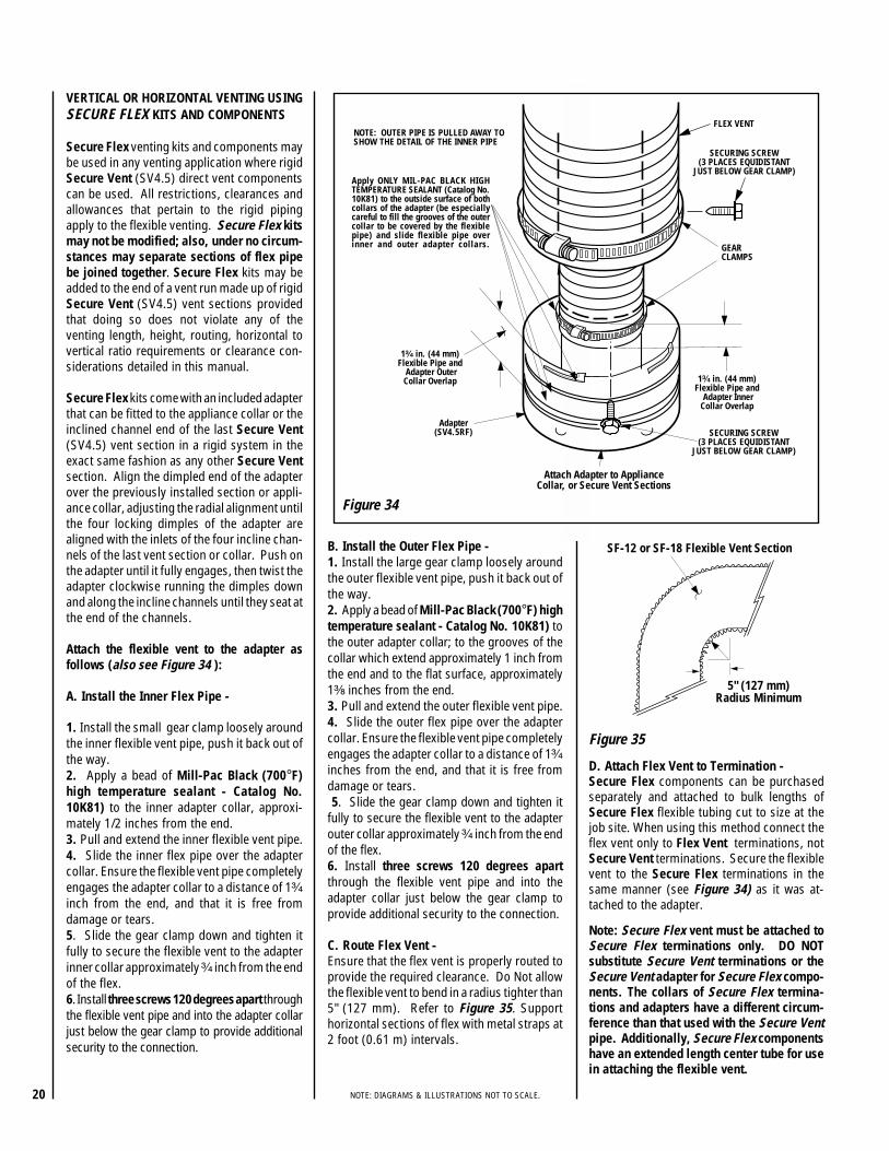
5" (127 mm)Radius Minimum
SF-12 or SF-18 Flexible Vent Section
GEARCLAMPS
Adapter(SV4.5RF)
Apply ONLY MIL-PAC BLACK HIGHTEMPERATURE SEALANT (Catalog No.10K81) to the outside surface of bothcollars of the adapter (be especiallycareful to fill the grooves of the outercollar to be covered by the flexiblepipe) and slide flexible pipe overinner and outer adapter collars.
NOTE: OUTER PIPE IS PULLED AWAY TOSHOW THE DETAIL OF THE INNER PIPE
FLEX VENT
1³⁄₄ in. (44 mm)Flexible Pipe and
Adapter OuterCollar Overlap 1³⁄₄ in. (44 mm)
Flexible Pipe and Adapter InnerCollar Overlap
SECURING SCREW(3 PLACES EQUIDISTANT
JUST BELOW GEAR CLAMP)
Attach Adapter to ApplianceCollar, or Secure Vent Sections
SECURING SCREW(3 PLACES EQUIDISTANT
JUST BELOW GEAR CLAMP)
Figure 35
Figure 34
VERTICAL OR HORIZONTAL VENTING USINGSECURE FLEX KITS AND COMPONENTS
Secure Flex venting kits and components maybe used in any venting application where rigidSecure Vent (SV4.5) direct vent componentscan be used. All restrictions, clearances andallowances that pertain to the rigid pipingapply to the flexible venting. Secure Flex kitsmay not be modified; also, under no circum-stances may separate sections of flex pipebe joined together. Secure Flex kits may beadded to the end of a vent run made up of rigidSecure Vent (SV4.5) vent sections providedthat doing so does not violate any of theventing length, height, routing, horizontal tovertical ratio requirements or clearance con-siderations detailed in this manual.
Secure Flex kits come with an included adapterthat can be fitted to the appliance collar or theinclined channel end of the last Secure Vent(SV4.5) vent section in a rigid system in theexact same fashion as any other Secure Ventsection. Align the dimpled end of the adapterover the previously installed section or appli-ance collar, adjusting the radial alignment untilthe four locking dimples of the adapter arealigned with the inlets of the four incline chan-nels of the last vent section or collar. Push onthe adapter until it fully engages, then twist theadapter clockwise running the dimples downand along the incline channels until they seat atthe end of the channels.
Attach the flexible vent to the adapter asfollows (also see Figure 34 ):
A. Install the Inner Flex Pipe -
1. Install the small gear clamp loosely aroundthe inner flexible vent pipe, push it back out ofthe way.2. Apply a bead of Mill-Pac Black (700°F)high temperature sealant - Catalog No.10K81) to the inner adapter collar, approxi-mately 1/2 inches from the end.3. Pull and extend the inner flexible vent pipe.4. Slide the inner flex pipe over the adaptercollar. Ensure the flexible vent pipe completelyengages the adapter collar to a distance of 1³⁄₄
inch from the end, and that it is free fromdamage or tears.5. Slide the gear clamp down and tighten itfully to secure the flexible vent to the adapterinner collar approximately ³⁄₄ inch from the endof the flex.6. Install three screws 120 degrees apart throughthe flexible vent pipe and into the adapter collarjust below the gear clamp to provide additionalsecurity to the connection.
B. Install the Outer Flex Pipe -1. Install the large gear clamp loosely aroundthe outer flexible vent pipe, push it back out ofthe way.2. Apply a bead of Mill-Pac Black (700°F) hightemperature sealant - Catalog No. 10K81) tothe outer adapter collar; to the grooves of thecollar which extend approximately 1 inch fromthe end and to the flat surface, approximately1³⁄₈ inches from the end.3. Pull and extend the outer flexible vent pipe.4. Slide the outer flex pipe over the adaptercollar. Ensure the flexible vent pipe completelyengages the adapter collar to a distance of 1³⁄₄
inches from the end, and that it is free fromdamage or tears. 5. Slide the gear clamp down and tighten itfully to secure the flexible vent to the adapterouter collar approximately ³⁄₄ inch from the endof the flex.6. Install three screws 120 degrees apartthrough the flexible vent pipe and into theadapter collar just below the gear clamp toprovide additional security to the connection.
C. Route Flex Vent -Ensure that the flex vent is properly routed toprovide the required clearance. Do Not allowthe flexible vent to bend in a radius tighter than5" (127 mm). Refer to Figure 35. Supporthorizontal sections of flex with metal straps at2 foot (0.61 m) intervals.
Note: Secure Flex vent must be attached toSecure Flex terminations only. DO NOTsubstitute Secure Vent terminations or theSecure Vent adapter for Secure Flex compo-nents. The collars of Secure Flex termina-tions and adapters have a different circum-ference than that used with the Secure Ventpipe. Additionally, Secure Flex componentshave an extended length center tube for usein attaching the flexible vent.
D. Attach Flex Vent to Termination -Secure Flex components can be purchasedseparately and attached to bulk lengths ofSecure Flex flexible tubing cut to size at thejob site. When using this method connect theflex vent only to Flex Vent terminations, notSecure Vent terminations. Secure the flexiblevent to the Secure Flex terminations in thesame manner (see Figure 34) as it was at-tached to the adapter.

21NOTE: DIAGRAMS & ILLUSTRATIONS NOT TO SCALE.
Step 4. FIELD WIRING
Note: This appliance must be connected to themain power supply.
The junction box assembly is located insidethe control compartment close to the frontright side corner (see Figure 36 ). This junc-tion box contains a standard electrical junctionbox, pre-wired duplex receptacle, a cover plateand a conduit fitting (clamp connector). Ifdesired, the whole junction box assembly maybe moved to the left hand side of the controlcompartment. A knock-out is provided on thecabinet wrapper for positioning.
1. Route a 3-wire 120Vac 60Hz 1 ph powersupply to the appliance.
2. Remove the metal cover plate and the duplexreceptacle from the junction box assembly.
3. From the outside of the fireplace, loosenclamp screws on the conduit fitting. Run powersupply wires (including the ground supply wire)through conduit fitting. Tighten mounting nutof conduit fitting.
4. Connect the power supply wires to the duplexreceptacle as shown in Figure 37.
5. Reassemble duplex receptacle and coverplate on junction box. Tighten conduit fittingclamp screws to secure supply wires.
6. Insert the control circuit plug from the gasvalve into the duplex receptacle. Figure 37
BLOWER
BK
BK
G
G
W
W
WGAS
VALVE
JUNCTIONBOX
FACTORY WIRED
FIELD WIRED
BK GW
GasStub
¹ ₂" x ³ ₈" FlareShut-Off Valve
³ ₈" Flex Tubing
³ ₈" NPT x ³ ₈Flare Fitting
³ ₈" Nipple
³ ₈" Union
³ ₈" Close Nipple
³ ₈" Shut-Off Valve
¹ ₂ x ³ ₈ "Reducer
GasValve
Gas Flex Line Connector
Figure 38- GAS CONNECTION
A manual shut off valve is also provided withthe flex line. The gas control valve is locatedin the lower control compartment (refer toFigure 44). The RF control millivolt valvehas a 1/2" (13 mm) NPT thread inlet port.
Secure all joints tightly using appropriatetools and sealing compounds (ensure pro-pane resistant compounds are used in pro-pane applications).
Turn on gas supply and test for gas leaks,using a gas leak test solution (also referred toas bubble leak solution).
Note: Using a soapy water solution (50% dishsoap, 50% water) is an effective leak testsolution but it is not recommended, becausethe soap residue that is left on the pipes/fittings can result in corrosion over time. Neveruse an open flame to check for leaks.
A. Light the appliance (refer to the lightinginstructions label in the control compartmentor in the Homeowner's Care and OperationInstructions).
B. Brush all joints and connections with thegas leak test solution to check for leaks. Ifbubbles are formed, or gas odor is detected,turn the gas control knob to the “OFF” posi-tion. Either tighten or refasten the leakingconnection and retest as described above.
C. When the gas lines are tested and leak free,be sure to rinse off the leak testing solution.
D. When the gas lines are tested and leak free,observe the individual tongues of flame on theburner. Make sure all ports are open andproducing flame evenly across the burner. Ifany ports are blocked, or partially blocked,clean out the ports.
Junction Box
Figure 36
Step 5. CONNECTING GAS LINE
Make gas line connections. All codes require ashut-off valve mounted in the supply line. Fig-ure 38 illustrates two methods for connectingthe gas supply. The flex-line method is accept-able in the U.S., however, Canadian require-ments vary depending on locality. Installationmust be in compliance with local codes.
These appliances are equipped with a gas flexline for use (where permitted) in connectingthe unit to the gas line. A gas flex line isprovided to aid in attaching the direct ventappliance to the gas supply.
The gas flex line can only be used where localcodes permit. See Figure 38 for flex linedescription. The flex line is rated for bothnatural and propane gas.
WARNING: THIS APPLIANCE IS EQUIPPEDWITH A THREE-PRONG (GROUNDING)PLUG FOR YOUR PROTECTION AGAINSTSHOCK HAZARD AND SHOULD BEPLUGGED DIRECTLY INTO A PROPERLYGROUNDED THREE-PRONGED RECEP-TACLE. DO NOT CUT OR REMOVE THEGROUNDING PRONG FROM THIS PLUG.

22 NOTE: DIAGRAMS & ILLUSTRATIONS NOT TO SCALE.
INSTRUCTIONS FOR RF COMFORTCONTROL VALVE
The Comfort Control Valve allows remote con-trol of temperature, fan and flame appearance.
Note: The antenna should hang in free air andaway from any grounded metal.
Operation (refer to Figure 39 )
Step 1. If the manual switch is in the remoteposition, switch it to LOCAL.
Step 2. Turn the Pilotstat knob counter-clockwise from OFF to the PILOT position,push the knob down and hold it in position.The pilot valve will open and allow gas to flowto the pilot burner.
Step 3. Actuate the plunger on the piezo(several times if necessary) until the pilotburner is lit. When the pilot burner is lit, theLED on the control will come on after ap-proximately 40 seconds. The receiver/valveis fully powered.
Step 4. Release the knob. The shaft willmove forward. The pilot burner should nowstay burning. If the pilot burner goes out,repeat Steps 2 and 3.
Step 5. Turn the knob counterclockwise tothe ON position. If the manual switch is in theLOCAL position, the main burner will turn onimmediately.
Step 6. ON the initial use of a transmitter, arecognition operation is required between thereceiver/valve and transmitter. Change the switchfrom LOCAL to REMOTE. Press the fan or flamebutton on the transmitter within 30 seconds.The LED will blink indicating the transmitter willnow work with the receiver/valve. If the switchcontinues in the REMOTE position, the transmit-ter will now control the main valve, flame modu-lation level and fan control.
Step 7. If the manual switch is in the LOCALposition, the valve will be at the highest fixedpressure setting. The transmitter will controlthe fan only.
Shut Off Procedure
If the manual switch is in the REMOTE posi-tion, the transmitter can shut off the mainburner and fan. However, the control is still onand a command from the transmitter can turnon the main burner or fan.
To shut off the system, turn the pilotstat knobclockwise to the OFF position. This action closesthe main gas and safety valves. The transmitternow cannot turn on the main burner or fan.
Piezo Ignitor
Local/RemoteSwitch
AntennaPilotstatKnob
LED
Screw Cap Of PilotAdjustment
Display- Room Temperature- Set Temperature- Flame Height Level- Fan Speed Level- Countdown Timer- Low Battery
CountdownTimer
Flame
Fan
Up(Increases FlameHeight, Fan SpeedTimer, or Set Point)
Down(Decreases Flame,Fan Speed Timer,or Set Point)
Mode- Auto
- On- Off
TRANSMITTER OPERATION -(refer to Figure 40 )
Off Mode
In the OFF mode, the fireplace flame and fanare off, the display will show OFF and displaysthe room temperature. If the receiver is inREMOTE mode, the fireplace will shut off.
On (Manual) Mode
In the ON mode, the room temperature, flameand fan levels will be shown. MANUAL willappear next to both the flame and fan icons.
When the control is in the ON mode, the flameand fan levels, and the delay timer are changedwith the up and down buttons. To change theflame level, press the flame button followed byan arrow key. To change the fan level, press thefan key followed by an arrow key. Pushing thearrow key once will change the level by one unit.
Delay Timer Mode
The shut off delay timer has a maximum of 2(two) hours and a minimum of 0 (zero) min-utes. To change the timer level, press the timekey followed by an arrow key. Pushing the keyonce will change the timer by 10 (ten) minutes.
Auto Mode
In the AUTO mode, the room temperature, settemperature, flame and fan levels will be shown.AUTO will appear next to both the flame andfan icons.
When the control is in the AUTO mode, the mainburner will turn on/off or modulate based on theheat needed to maintain the set temperature.The flame level will change automatically tooptimize the heat output needed to maintain theset temperature. To change the set tempera-ture, press the up or down key. Pushing a keyonce will change the temperature by 1 (one)degree. The setting temperature range from40° F (4.5° C) to 90° F (32.0° C).
Figure 39
Figure 40

23NOTE: DIAGRAMS & ILLUSTRATIONS NOT TO SCALE.
In the AUTO mode, the fan speed will increasewith increasing flame height or decrease withdecreasing flame height. "AUTO" is displayednext to the flame and fan icons.
Fan Override During Auto Mode
If a lower or higher fan speed is desired whenoperating in the AUTO mode, the fan speed canbe overridden by pushing the fan button fol-lowed by the up or down key.
Pushing a key once will change the fan level byone unit. In this mode "AUTO" is displayed nextto the flame icon and "MANUAL" is displayednext to the fan icon.
Change Between F/C Temperature Units
Push the up and down arrow keys simulta-neously for at least 3 seconds to toggle be-tween Fahrenheit and Celsius units.
Disable Thermostat Function
To disable the thermostat function in the AUTOmode, push the time and down key simulta-neously for at least 3 seconds.
To Change Batteries
1. Remove cover on the backside of the trans-mitter. Install 3 AAA batteries as shown insidethe cover and reattach the cover.
COMFORT VALVE WIRING DIAGRAM
2. Once steps 1 thru 3 in OPERATION arecompleted, receiver/valve and transmitter arenow ready. Press any button on transmitterfor recognition precess to occur between thereceiver/valve and transmitter.
3. Use functions as described in TRANSMIT-TER section.
Troubleshooting
Step 1. Locate LED light on valve.
Step 2. LED will blink after every valid commandreceived by the transmitter; this is not an error.
Step 3. Failure codes may occur anytime afterpilot burner is lit.
Step 4. Sequence is failure code followed bylight not blinking for 4 seconds.
Step 5. In the event of multiple failure codes,next failure code follows previous failure codeby approximately 3 seconds
If an Error Code 3 is observed while perform-ing the testing, complete the following:
Step 1. Make sure the spade connectors arepushed all the way on. If the Error Code 3 isstill showing, then go to the next step.
Step 2. Switch the front two thermopile leadswith the back two. Be sure the lead is con-nected to the spade with the white dot next toit (see Figure 41 ). If the Error Code 3 is stillshowing, replace the thermopiles.
If an Error Code 8 is observed while perform-ing the testing, complete the following:
Step 1. Confirm that the valve is not inREMOTE mode.
• If the valve is producing Error Code 8 and inREMOTE mode, the valve is defective andshould be replaced.
• If the valve is in LOCAL mode and producingError Code 8, then go to the next step.
Step 2. Slide the Remote/Local switch toREMOTE and reprogram valve recognition (re-fer to in Operation section). The Error Codewill clear itself after approximately 1 1/2 min-utes and return to normal operation.
LED Failure Code Service Action(Number Of Blinks)
8 Replace valve
7 Confirm stepper motorconnection exists
5 Confirm fan connectionexists and works
4 Confirm gas type; jumperin place
3 Replace thermopiles
2 Turn fan ON
1 No action required
NOTE: Some keys are not active. This isnormal.
AUTO PATH DIAGRAM
Figure 41 Figure 42
BLOWER
WHITE
BLACK
GREEN
BLACK
GREEN
F
MF
F M
REDWHITE
REDWHITE
VALVE
F
WHITE
WhiteDots
CAUTION: LABEL ALL WIRES PRIOR TODISCONNECTION WHEN SERVICING CONTROLS.WIRING ERRORS CAN CAUSE IMPROPER ANDDANGEROUS OPERATION. VERIFY PROPEROPERATION AFTER SERVICING.

24 NOTE: DIAGRAMS & ILLUSTRATIONS NOT TO SCALE.
Figure 45
ThermopileIgnitor Rod
Hood
³⁄₈" Min(9 mm)
Thermopile
MILLIVOLT HONEYWELL
PilotNozzels
³⁄₈" Min(9 mm)
Typically, the top 3/8" of the thermopile should beengulfed in the pilot flame (Figure 45 ).
To adjust pilot burner; (by a qualified servicetechnician), refer to Figure 39.
1. Remove pilot adjustment screw cap.
2. Adjust pilot screw to provide properly sizedflame.
3. Replace pilot adjustment screw cap.
The primary air shutter is set at the factory andshould only be adjusted, if necessary, by aqualified service technician.
Step 6. INSTALLING CERAMIC PANEL,LOGS AND GLOWING EMBERS
The packaged logs are located within thefirebox. The glowing embers are packagedseparately in plastic bags located in thecontrol area of the fireplace. Refer to the LogPlacement Guide for detailed placement in-structions for ceramic panel, logs and glow-ing embers (rockwool).
Figure 44
Honeywell RF Control Millivolt Gas ValveShowing Piezo Ignitor Location
PiezoIgnitor
HoneywellGas Valve
Note: Instructions are also found on the litera-ture tag attached to the gas valve train.
When first lighting the appliance, it will take a fewminutes for the line to purge itself of air. Oncepurging is complete, the pilot and burner will lightand operate as indicated in the instruction manual.Subsequent lightings of the appliance will not re-quire such purging. Inspect the pilot flame (removelogs, if necessary, handling carefully).
Honeywell RF Control Millivolt AppliancePilot Checkout
Pilot Inspection
To obtain proper operation, it is imperative thatthe pilot and burner's flame characteristics aresteady, not lifting or floating (see Figure 45 ).
Step 7. CHECKING APPLIANCE OPERATION
With gas line installed run initial system check-out before closing up the front of the unit.Follow the pilot lighting instructions pro-vided in the Homeowner's Care and Opera-tion Instructions. For piezo ignitor locationsee Figure 44.
Comfort Valve System Control Sequence Of Operation With Transmitter
Figure 43
Step 8. INSTALLING THE GLASS DOOR
Retrieve the glass door. Visually inspect thegasket on the backside of the frame. Gasketsurface must be clean, free of irregularitiesand seated firmly.

25NOTE: DIAGRAMS & ILLUSTRATIONS NOT TO SCALE.
Figure 47
Figure 46
INSTALLING THE GLASS DOOR
Sooting is indicated by black puffs developing atthe tips of very long orange flames. Sootingresults in black deposits forming on the logs,appliance inside surfaces and on exterior sur-faces adjacent to the vent termination.
Sooting is caused by incomplete combustion inthe flames and lack of combustion air enteringthe air shutter opening. To achieve a warmyellow to orange flame with an orange body thatdoes not soot, the shutter opening must beadjusted between these two extremes.
No smoke or soot should be present. Repositionthe logs if flames impinge on any of them.If the logs are properly positioned and sootingconditions exist, the air shutter opening on themain burner tube should be adjusted. Normally,the more offsets in the vent system, the greaterthe need for the air shutter to be opened further.
To adjust the flame, rotate the air shutteradjustment rod toward the back or towardthe front of the fireplace (rod located in thelower control area). Position the air shutterto the factory setting as shown in the Tableof Figure 47. Allow the burner to operate forat least 15 minutes. Observe the flame con-tinuously. If it appears weak or sooty aspreviously described, adjust the air shutterby pushing or pulling on the adjustment roduntil the flame appearance is as desired.
The air shutter adjustment rod and associatedadjustable air shutter is patented technology.Flame adjustments can be made quickly andaccurately to taste without the need of disassem-bling the appliance and waiting for 30 minutesafter each adjustment.
When satisfied that the appliance operatesproperly, proceed to finish the installation.Leave the control knob in the ON positionand the remote switch OFF.
Vent Restrictor
The appliance has a built-in vent restrictor,refer to Figure 46 for location, to adjust theflow of exhaust gases. This ensures propercombustion for all vent configurations. De-pending on the vent configuration, you maybe required to adjust the restriction position.See below for guidelines.
Burner Adjustment
Position the door in front of the firebox openingwith the bottom of the door held away from thefireplace (Figure 46 ). Hook the top flange of thedoor frame over the top of the firebox frame.
Let the bottom of the door frame swing gentlyin towards the fireplace ensuring that the gas-ket seats evenly as the door frame draws shut.Fasten the two latches located underneath thefirebox floor to the door's vee-flange. Closeboth the latches securely.
sledoM saGepyT
RIAYROTCAFGNITTESRETTUHS
GNINEPO)mm(sehcni
53-SSL.taN 2/1 )0.31(.porP 8/5 )8.51(
04-SSL.taN 2/1 )0.31(.porP 8/5 )8.51(
Step 9. BURNER ADJUSTMENTS
Flame Appearance and sooting
Proper flame appearance is a matter of taste.Generally, most people prefer the warm glow ofa yellow to orange flame. Appliances operatedwith air shutter openings that are too large willexhibit flames that are blue and transparent.These weak, blue and transparent flames aretermed anemic. If the air shutter opening is toosmall sooting may develop. * Adjustment to the air shutter may be re-
quired to get the desired flame appearance,(refer to Figure 47 ).
1. Horizontal Ventingwith 6" vent section andone 90° elbow.
* Pointed toward the front.
2. Vertical venting.
3. Combination of ver-tical and horizontalventing.
* Pointed toward the left.
* Adjust accordingly for best result.
Air ShutterOpening
BurnerVenturi
Tube
AirShutter
Door
Orifice
Air ShutterAdjusting
Rod
VentingConfiguration
Adjustment RodPosition
Latch
Latch
Glass Door
Firebox Floor
Bottom Vee-flangeDoor Frame
Top FlangeDoor Frame Vent Restrictor
Adjustment Rod
WARNING: AIR SHUTTER ADJUSTMENTSHOULD ONLY BE PERFORMED BY AQUALIFIED PROFESSIONAL SERVICETECHNICIAN.
IMPORTANT: ENSURE THAT THE FRONTGLASS PANEL IS IN PLACE AND SEALEDDURING ADJUSTMENT.
CAUTION: THE AIR SHUTTER ADJUST-MENT ROD AND NEARBY APPLIANCESURFACES ARE HOT. EXERCISE CAU-TION TO AVOID INJURY WHILE ADJUST-ING FLAME APPEARANCE.
WARNING: HANDLE THIS GLASS WITH EX-TREME CARE! THE GLASS PANEL IS SUS-CEPTIBLE TO DAMAGE — DO NOT SCRATCHWHILE HANDLING OR WHILE RE-INSTALL-ING THE GLASS DOOR FRAME.
WARNING: DO NOT OPERATE APPLI-ANCE WITH THE GLASS FRONT RE-MOVED, CRACKED OR BROKEN. RE-PLACEMENT OF THE GLASS SHOULDBE DONE BY A LICENSED OR QUALIFIEDSERVICE PERSON.
CAUTION: THE FIREPLACE NEEDS TO BE ONDURING THE ADJUSTMENT OF THE VENTRESTRICTOR. USE A GLOVE TO PROTECTYOUR HAND FROM BURNS.

26 NOTE: DIAGRAMS & ILLUSTRATIONS NOT TO SCALE.
Figure 48 Figure 50
Mantels constructed of non-combustible ma-terials may be installed above the applianceopening; however, do not allow anything tohang below the openings on the facade andcast iron kits. Refer to Figure 7 on page 6 forclearance requirements.
Non-combustible materials, such as facadesand cast iron kits, may be installed on theappliance front face.
Vertical installation clearances to combustiblemantels vary according to the depth of themantel. See Figure 50.
This Area MustRemain Clear ofCombustibleMaterials
3" Min (76 mm)
Stand-Off
1/2”Cement
Board
Marble,Tile, Or
Other Non-Combustible
Materials Fireplace
2”x 4”Header
1/2”Drywall
1" Min(25.4 mm)
1/2” Drywall
12 (305) MANTEL
10 (254) MANTEL
8 (203) MANTEL
6 (152) MANTEL
4 (102) MANTEL
16(406)
26(660)
24(610) 22
(559)2 (51) MANTEL
Top OfFireplaceOpening
18(457)
20(508)
MANTEL CLEARANCESInches (mm)
FINISHING REQUIREMENTSWall Details
Complete finished interior wall. To install theappliance facing flush with the finished wall,position framework to accommodate thethickness of the finished wall (Figure 48 ).
Note: Never allow combustible materials tobe positioned in front of or overlapping theappliance front face. See Figure 48 and referto Figure 7 on page 6.
Combustible materials may project beyond thesides of the fireplace opening as long as theyare kept within the shaded areas illustrated inFigure 49.
Figure 49
17"
14"Min. Distance ToUnprotected Side Wall
45°
CombustibleMaterialsAllowed InShadedArea “SafeZone”
12"
5"
Min. DistanceTo ProtectedSide Wall
Top View OfFireplace
SideWall Side
Wall
8 ¹⁄₄"
Combustible MaterialsNot Allowed In This Area
4 ¹⁄₂"
COLD CLIMATE INSULATION
For cold climate installations, seal all cracks around your appliance with noncombustible materialand wherever cold air could enter the room. It is especially important to insulate outside chasecavity between studs and under floor on which appliance rests, if floor is above ground level. Gasline holes and other openings should be caulked or stuffed with unfaced fiberglass insulation. Incold climates, if the fireplace is being installed on a cement slab, a sheet of plywood or other raisedplatform can be placed underneath to prevent conducting cold up into the room. It also helps tosheetrock inside surfaces and tape for maximum air tightness and caulk firestops.

27NOTE: DIAGRAMS & ILLUSTRATIONS NOT TO SCALE.
*All compressed flex vents can be expanded up to two times.
INSTALLATION ACCESSORIES
detsiL tneVeruceS stnenopmoC™.oN.taC .oNledoM noitpircseD30L9920L99
63KRH5.4VS41KRH5.4VS
"63tiKresiRlatnoziroH"41tiKresiRlatnoziroH
8691H 2-TH5.4VS erauqSlatnoziroHhtiwnoitanimreT
)08K69(recapS/potseriF)16L47(retpadAdna
detsiL xelFeruceS stnenopmoC™.taC.oN
ledoM.oN noitpircseD
.retpadaxelfdnaspmalcraeg,recaps/potserifedulcnistiknoitanimretesehT9691H 2-TH5.4FS noitanimreTerauqSlatnoziroH
xelFtuohtiw78L77 21TIKFS .ni21htiw.mreTerauqSxelF
xelFdesserpmoc*fomm503(88L77 81TIKFS .ni81htiw.mreTerauqSxelF
xelFdesserpmoc*fo)mm754(98L77 42TIKFS .ni42htiw.mreTerauqSxelF
xelFdesserpmoc*fo)mm016(09L77 63TIKFS .ni63htiw.mreTerauqSxelF
xelFdesserpmoc*fo)mm419(19L77 84TIKFS .ni84htiw.mreTerauqSxelF
xelFdesserpmoc*fo)mm9121(
detsiL tneVeruceS stnenopmoC™.oN.taC .oNledoM noitpircseD2512H 1-VGC5.4VS noitanimreTlacitreV
7864H6174H7174H
STC5.4VSB-STC5.4VSCT-STC5.4VS
erauqS.mreTpoTesahC.klB,erauqS.mreTpoTesahC
noitanimreTattoCarreT07L77 6L5.4VS noitceStneV)mm251(hcni6
17L77 21L5.4VS tneV)mm503(hcni21noitceS
27L77 42L5.4VS tneV)mm016(hcni42noitceS
37L77 63L5.4VS tneV)mm419(hcni63noitceS
47L77 84L5.4VS tneV)mm9121(hcni84noitceS
57L77 AL5.4VS noitceScipocseleT67L77 54E5.4VS woblEeergeD54
77L77 09E5.4VS woblEeergeD09
.rallocmrotsahtiwdegakcapemocsgnihsalfgniwollofehT87L77 F5.4VS gnihsalFfooRtalF97L77 AF5.4VS gnihsalF.tsujdA21/7ot21/108L77 BF5.4VS gnihsalF.tsujdA21/21ot21/718L77 6CS5.4VS )xob/sralloc6(sralloCmrotS
6422H FH5.4VS kcaP01-recapS/potseriF)gnicaps1-1-3(latnoziroH
7422H FV5.4VS kcaP01-recapS/potseriF)gnicaps1-1-1(lacitreV
39K69 US5.4VS partStroppuS
49K69 ASR5.4VS dleihSnoitalusnIcittA
29K69 PS5.4VS etalPtroppuS
25M71 5.4VS1-SGH
erauqSdrauGtaeH)kcaP-1(
35M71 5.4VS21-SGH
erauqSdrauGtaeH)kcaP-21(
detsiL xelFeruceS stnenopmoC™.taC.oN
ledoM.oN noitpircseD
47L65 03TVFS ottalf(xelFrof.nimreTlacitreVnoitces,retpadAxelFhtiw)21/6ralloctroppusfoor,tnevdigirfo
dnagnihsalffoor,ylbmessa.rallocmrots
57L65 54TVFS ot21/6(xelFrof.nimreTlacitreVnoitcesretpadAxelFhtiw)21/21ralloctroppusfoor,tnevdigirfo
dnagnihsalffoor,ylbmessa.rallocmrots
8891H
5891H
7891H
6891H
33-ASTC
33-OSTC
44-OSTC
64-OSTC
,tiKduorhSpoTesahC3X3-poThcrA
,tiKduorhSpoTesahC3X3-poTnepO
,tiKduorhSpoTesahC4X4-poTnepO
,tiKduorhSpoTesahC6X4-poTnepO
01L06 81-FS xelFdesserpmoc*)m94.5(.tf8130K89 21-FS xelFdesserpmoc*)m66.3(.tf2118K01
04L98
PMFS
21-PMFS
erutarepmeT-iHkcalBcaPliMtnalaeS
erutarepmeT-iHkcalBcaPliM21kcaPkluB-tnalaeS
66L19 6-4CG-FS rof)mm411(.ni5.4pmalCraeG)seceip6(xelF
76L19 6-7CG-FS )mm5.091(.ni5.7pmalCraeG)seceip6(xelFrof
8422H FH5.4FS kcaP01-recapS/potseriF)gnicaps1-1-3(latnoziroH
9422H FV5.4FS kcaP01-recapS/potseriF)gnicaps1-1-1(lacitreV
Seala
nt

28 NOTE: DIAGRAMS & ILLUSTRATIONS NOT TO SCALE.
GAS CONVERSION KITS
In Canada
THE CONVERSION SHALL BE CARRIED OUTIN ACCORDANCE WITH THE REQUIREMENTSOF THE PROVINCIAL AUTHORITIES HAVINGJURISDICTION AND IN ACCORDANCE WITHTHE REQUIREMENTS OF THE CAN1-B149.1AND .2 INSTALLATION CODE.
LA CONVERSION DEVRA ÊTRE EFFECTUÉECONFORMÉMENT AUX RECOMMANDATIONSDES AUTORITÉS PROVINCIALES AYANTJURIDICTION ET CONFORMÉMENT AUXEXIGENCES DU CODE D'INSTALLATION CAN1-B149.1 ET.2.
This Gas Conversion Kit contains all of thenecessary components needed to completethe conversion of an appliance from the use ofone type of gas to the use of another, includinglabeling that must be affixed to ensure safeoperation.
ALWAYS REFER TO THE APPLIANCE IN-STALLATION AND HOMEOWNERS CAREAND OPERATION DOCUMENTS BEFORECOMPLETING A CONVERSION. ALLWARNINGS, CAUTIONS AND DETAILEDINSTRUCTIONS CONTAINED THEREINARE APPLICABLE TO THIS DOCUMENT.
To complete the conversion proceed as follows:
Note: After converting the valve and gas compo-nents, refer to the appliance installation andhomeowners care and operation instructions toadjust the air shutter opening for the gas type used.
Step 1. Turn off the gas supply to theappliance. Remove the front frame andglass door from the appliance. Access thecontrol compartment.
Step 2. Carefully remove the logs. Exercisecare as not to break the logs.
Step 3. Remove the grate.
Figure 51
See Figure 51 for step 4 part removal details:
Step 4
a. Remove the front baffle by removing thetwo securing screws.
b. Remove the two screws securing the endtabs of the front burner. Remove the frontburner.
c. Remove the two screws securing each ofthe rear burner clamps. Remove the rearburner.
Burner Assembly
Front Baffle
Front BaffleSecuring Screw
Front Burner
Front BurnerSecuring Screw
Burner ClampSecuring Screw Rear Burner
Burner Clamp
WARNING: THIS CONVERSION KIT SHALL BEINSTALLED BY A QUALIFIED SERVICE AGENCY INACCORDANCE WITH THE MANUFACTURER'S IN-STRUCTIONS AND ALL APPLICABLE CODES ANDREQUIREMENTS OF THE AUTHORITY HAVING JU-RISDICTION. IF THE INFORMATION IN THESEINSTRUCTIONS IS NOT FOLLOWED EXACTLY, AFIRE, EXPLOSION OR PRODUCTION OF CARBONMONOXIDE MAY RESULT CAUSING PROPERTYDAMAGE, PERSONAL INJURY OR LOSS OF LIFE.THE INSTALLATION IS NOT PROPER AND COM-PLETE UNTIL THE OPERATION OF THE CONVERTEDAPPLIANCE IS CHECKED AS SPECIFIED IN THEOWNER INSTRUCTIONS SUPPLIED WITH THE KIT.THE QUALIFIED SERVICE AGENCY PERFORMINGTHIS INSTALLATION ASSUMES RESPONSIBILITYFOR THIS CONVERSION.
AVERTISSEMENT: CET ÉQUIPEMENT DE CONVERSIONSERA INSTALLÉ PAR UNE AGENCE QUALIFIÉE DE SERVICECONFORMÉMENT AUX INSTRUCTIONS DU FABRICANT ETTOUTES EXIGENCES ET CODES APPLICABLES DEL'AUTORISÉS AVOIR LA JURIDICTION. SI L'INFORMATIONDANS CETTE INSTRUCTION N'EST PAS SUIVIEEXACTEMENT, UN FEU, EXPLOSION OU PRODUCTION DEPROTOXYDE DE CARBONE PEUT RÉSULTER LE DOMMAGESCAUSER DE PROPRIÉTÉ, PERTE OU BLESSUREPERSONNELLE DE VIE. L'AGENCE QUALIFIÉE DE SERVICEEST ESPONSABLE DE L'INSTALLATION PROPRE DE CETÉQUIPMENT. L'INSTALLATION N'EST PAS PROPRE ETCOMPLÉTE JUSQU'À L'OPÉRATION DE L'APPAREILCONVERTI EST CHÉQUE SUIVANT LES CRITÈRES ÉTABLISDANS LES INSTRUCTIONS DE PROPRIÉTAIREPROVISIONNÉES AVEC L'ÉQUIPEMENT.

29NOTE: DIAGRAMS & ILLUSTRATIONS NOT TO SCALE.
a. Convert the pilot orifice as follows (seeFigures 54, 55 and 56 on page 30 ):
Note - Use extra care not to engage theorifice strip with the 7/16" open end wrench(contacting the orifice strip could cause stripdistortion rendering the pilot inoperative).Also avoid wrench contact to any of the otherpilot parts.
Use a 7/16" open end wrench and turn the pilothex fitting counter-clockwise 1/4 turn. (SeeFigure 54 on page 30 ).
Note - The orifice strip tab may be randomlylocated on any side of the hex fitting.
b. Push the orifice strip tab all the way againstthe hex fitting to align the appropriate gas typeorifice (see Figures 55 and 56 on page 30 ). Thetype of gas for which the pilot is set, is, the gastype shown on the tab.
c. Retighten, clockwise, the pilot hex fittinguntil the pilot hood aligns with the thermopilesas indicated by the arrows shown in Figure 54on page 30.
Step 5.
Convert the Honeywell RF Comfort ControlValve as follows:
a. Access the gas selector by removing themotor cover. Refer to Figure 52.
b. Using a slot-type screwdriver, push the gasselector down and rotate until the arrows on itpoint to the correctly colored screw: red forLP/propane gas usage or blue for naturalgas. Refer to Figure 52.
c. Insert the conversion plug for the fuel beingused as shown in Figure 53. Use the red plugfor LP/propane gas usage or the blue one fornatural gas.
d. Attach the correct gas conversion label tothe gas valve (see Figure 52 ).
e. Replace the motor cover.
Step 6.Figure 52
Figure 53
Adjusting the Fuel Selector on theHoneywell RF Comfort Control Valve
Insertion of the LP/propane or Natural Gas ConversionPlug on the Honeywell RF Comfort Control Valve
MOTOR COVER
GAS SELECTOR SCREW
RED SCREW (LP/propane)
BLUE SCREW (NATURAL GAS)
OR
PINS

30 NOTE: DIAGRAMS & ILLUSTRATIONS NOT TO SCALE.
Figure 58
Pilot for the Honeywell RF Comfort Control Valve(Loosening of Hex Fitting For Orifice Strip Tab Positioning)
Pilot for the Honeywell RF Comfort Control Valve
Pilot for the Honeywell RF Comfort Control ValveOrifice Strip Tab Positioning
Figure 55
Figure 56
Figure 54Figure 57
Step 7. Unscrew the rear and front mainburner orifices (see Figure 57) from theirrespective manifolds and replace them withthe ones provided in this kit. There are twomain burner orifices provided in this gasconversion kit. Refer to Table below for thecorrect front and rear main burner orificesizes for the gas being used. The orifice sizeis stamped on the orifice. See Figure 58.
size
Rear Main Burner Orifice
Front MainBurner Orifice
Gas Valve
Natural Gas Position -NAT shown on tab
LP/Propane Gas Position -1/16 in. Hole, LP and
Red Color shown on tab
NAT
PL
Orifice Strip Tab Position IdentificationFor LP/Propane and Natural Gas
Top View of Hex Fitting and Orifice Strip Tab
Hood AlignmentHood
7/16 in. Open End Wrench
Orifice Strip Tab
Take Care Not to Contact the Orifice Strip Tabwith the Hex Fitting Wrench - Distortion of the Tab
May Render the Pilot Inoperative.
Pilot Hood Position AfterLoosening Hex Fitting 1/4 Turn
Orifice Strip Tab
Push Tab to SetGas Type Usage
Note - Orifice Strip Tab May beRandomly Located on any
Side of the Hex Fitting
WARNING: INCORRECT ORIFICE SIZEINSTALLATION ON EITHER BURNERMAY RESULT IN POOR COMBUSTIONWHICH MAY LEAD TO THE PRODUC-TION OF CARBON MONOXIDE. IT MAYALSO CAUSE SOOTING WITHIN THEFIREPLACE/VENTING SYSTEM.
ledoM leuF raeRrenruB
tnorFrenruB
NC53-SSL saG.taN 44# 05#
PC53-SSL saGPL 55# 16#
NC04-SSL saG.taN 24# 54#
PC04-SSL saGPL "450.0 65#

31NOTE: DIAGRAMS & ILLUSTRATIONS NOT TO SCALE.
Step 10. Turn on gas supply and test for gasleaks, using a gas leak test solution.
Step 11. Attach a manometer to the manifoldside pressure test fitting and verify manifoldpressure reads 3.5 inches water column (0.87kPa) for natural gas, and 10.0 inches watercolumn (2.49 kPa) for propane gas.
Step 8. Reassemble all removed componentsby reversing the procedures outlined in thepreceding steps. Use pipe joint compound orTeflon tape on all pipe fittings before installing(ensure propane resistant compounds are usedin propane applications, do not use pipe jointcompounds on flare fittings). Adjust the airshutter opening on the burner tube, referringto the Note on page 28.
Step 9. Attach the conversion kit label(Figure 59 ) to the rating plate on theappliance. Example Labels
(Each Kit Contains Only One Label)
THIS APPLIANCE HAS BEEN CONVERTED TO:
NATURAL GASINPUT BTU/HR – 50,000
MANIFOLD PRESSURE – 3.5"
ORIFICE SIZE – (0.130)
THIS APPLIANCE HAS BEEN CONVERTED TO:
PROPANE/LPGINPUT BTU/HR – 50,000
MANIFOLD PRESSURE – 10"
ORIFICE SIZE – (0.080)
Figure 59

32 NOTE: DIAGRAMS & ILLUSTRATIONS NOT TO SCALE.
Printed in U.S.A. © 2002 by Lennox Hearth Products
P/N 850,016M REV. H 08/2007
Lennox Hearth Products reserves the right to make changes at any time, without notice, indesign, materials, specifications, prices and also to discontinue colors, styles and products.Consult your local distributor for fireplace code information.
1110 West Taft Avenue • Orange, CA 92865