DIRECT VENT FIREPLACE - IPI OWNER’S MANUAL Q4 Owners... · jurisdiction in your area regarding...
28
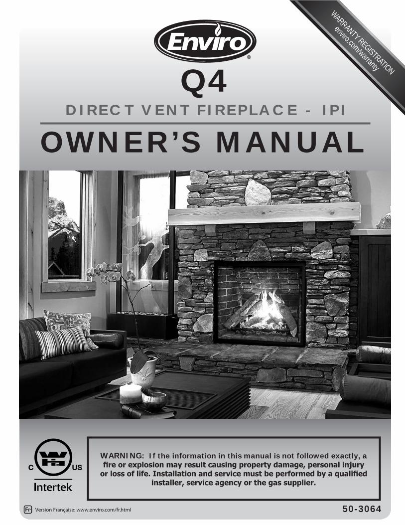
1 OWNER’S MANUAL 50-3064 WARNING: If the information in this manual is not followed exactly, a fire or explosion may result causing property damage, personal injury or loss of life. Installation and service must be performed by a qualified installer, service agency or the gas supplier. Version Française: www.enviro.com/fr.html WARRANTY REGISTRATION enviro.com/warranty Q4 DIRECT VENT FIREPLACE - IPI
Transcript of DIRECT VENT FIREPLACE - IPI OWNER’S MANUAL Q4 Owners... · jurisdiction in your area regarding...
1
OWNER’S MANUAL
50-3064
WARNING: If the information in this manual is not followed exactly, a fire or explosion may result causing property damage, personal injury
or loss of life. Installation and service must be performed by a qualified installer, service agency or the gas supplier.
Version Française: www.enviro.com/fr.html
WARRANTY REGISTRATION
enviro.com/warranty
Q4D I R E C T V E N T F I R E P L A C E - I P I

2
This appliance may be installed in an after-market permanently located, manufactured (mobile) home, where not prohibited by local codes.
This appliance is only for use with the type of gas indicated on the rating plate. This appliance is not convertible for use with other gases, unless a certified kit is used.
WARNING: FIRE OR EXPLOSION HAZARD Failure to follow safety warnings exactly could result in serious
injury, death, or property damage.
- Do not store or use gasoline or other flammable vapors and liquids in the vicinity of this or any other appliance.
- WHAT TO DO IF YOU SMELL GAS• Do not try to light any appliance.• Do not touch any electrical switch; do not use any phone in your
building.• Leave the building immeadiately.• Immeadiately call your gas supplier from a neighbor’s phone.
Follow the gas supplier’s instructions.• If you cannot reach your gas supplier, call the fire
department.
- Installation and service must be performed by a qualified installer, service agency or the gas supplier.
Massachusetts installations (Warning): This product must be installed by a licensed plumber or gas fitter when installed within the Commonwealth of Massachusetts. Other Massachusetts code requirements: Flexible connector must not be longer than 36in., a shut off valve must be installed; only direct vent sealed combustion products are approved for bedrooms/bathrooms. A carbon monoxide detector is required in all rooms containing gas fired direct vent appliances. The fireplace damper must be removed or welded in the open position prior to installation of a fireplace insert.
SAFETY PRECAUTIONS
INSTALLER: Leave this manual with the appliance.
CONSUMER:Retain this manual for future reference.
3
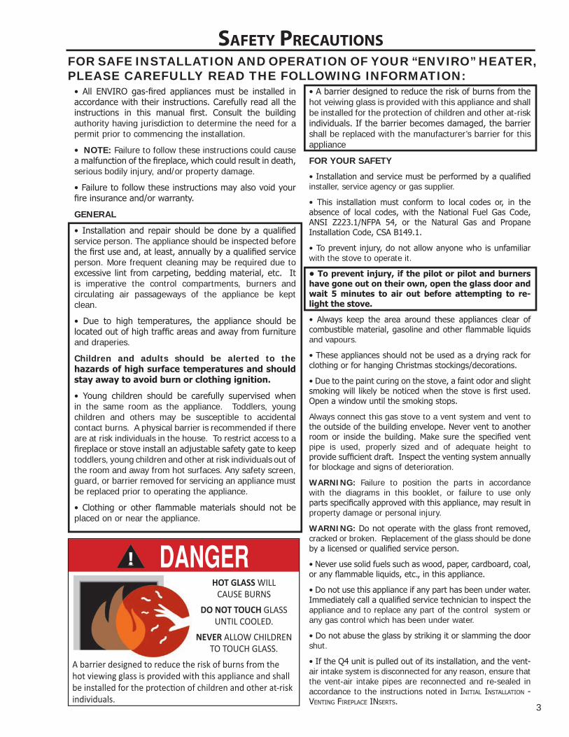
SAFETY PRECAUTIONSFOR SAFE INSTALLATION AND OPERATION OF YOUR “ENVIRO” HEATER, PLEASE CAREFULLY READ THE FOLLOWING INFORMATION:
• All ENVIRO gas-fi red appliances must be installed in accordance with their instructions. Carefully read all the instructions in this manual fi rst. Consult the building authority having jurisdiction to determine the need for a permit prior to commencing the installation.
• NOTE: Failure to follow these instructions could cause a malfunction of the fi replace, which could result in death, serious bodily injury, and/or property damage.
• Failure to follow these instructions may also void your fi re insurance and/or warranty.
GENERAL
• Installation and repair should be done by a qualifi ed service person. The appliance should be inspected before the fi rst use and, at least, annually by a qualifi ed service person. More frequent cleaning may be required due to excessive lint from carpeting, bedding material, etc. It is imperative the control compartments, burners and circulating air passageways of the appliance be kept clean.
• Due to high temperatures, the appliance should be located out of high traffi c areas and away from furniture and draperies.
Children and adults should be alerted to the hazards of high surface temperatures and should stay away to avoid burn or clothing ignition.
• Young children should be carefully supervised when in the same room as the appliance. Toddlers, young children and others may be susceptible to accidental contact burns. A physical barrier is recommended if there are at risk individuals in the house. To restrict access to a fi replace or stove install an adjustable safety gate to keep toddlers, young children and other at risk individuals out of the room and away from hot surfaces. Any safety screen, guard, or barrier removed for servicing an appliance must be replaced prior to operating the appliance.
• Clothing or other fl ammable materials should not be placed on or near the appliance.
• A barrier designed to reduce the risk of burns from the hot veiwing glass is provided with this appliance and shall be installed for the protection of children and other at-risk individuals. If the barrier becomes damaged, the barrier shall be replaced with the manufacturer’s barrier for this appliance
FOR YOUR SAFETY
• Installation and service must be performed by a qualifi ed installer, service agency or gas supplier.
• This installation must conform to local codes or, in the absence of local codes, with the National Fuel Gas Code, ANSI Z223.1/NFPA 54, or the Natural Gas and Propane Installation Code, CSA B149.1.
• To prevent injury, do not allow anyone who is unfamiliar with the stove to operate it.
• To prevent injury, if the pilot or pilot and burners have gone out on their own, open the glass door and wait 5 minutes to air out before attempting to re-light the stove.
• Always keep the area around these appliances clear of combustible material, gasoline and other fl ammable liquids and vapours.
• These appliances should not be used as a drying rack for clothing or for hanging Christmas stockings/decorations.
• Due to the paint curing on the stove, a faint odor and slight smoking will likely be noticed when the stove is fi rst used. Open a window until the smoking stops.
Always connect this gas stove to a vent system and vent to the outside of the building envelope. Never vent to another room or inside the building. Make sure the specifi ed vent pipe is used, properly sized and of adequate height to provide suffi cient draft. Inspect the venting system annually for blockage and signs of deterioration.
WARNING: Failure to position the parts in accordance with the diagrams in this booklet, or failure to use only parts specifi cally approved with this appliance, may result in property damage or personal injury.
WARNING: Do not operate with the glass front removed, cracked or broken. Replacement of the glass should be done by a licensed or qualifi ed service person.
• Never use solid fuels such as wood, paper, cardboard, coal, or any fl ammable liquids, etc., in this appliance.
• Do not use this appliance if any part has been under water. Immediately call a qualifi ed service technician to inspect the appliance and to replace any part of the control system or any gas control which has been under water.
• Do not abuse the glass by striking it or slamming the door shut.
• If the Q4 unit is pulled out of its installation, and the vent-air intake system is disconnected for any reason, ensure that the vent-air intake pipes are reconnected and re-sealed in accordance to the instructions noted in InItIal InStallatIon - ventIng fIrePlace InSertS.
HOT GLASS WILL CAUSE BURNS
DO NOT TOUCH GLASS UNTIL COOLED.
NEVER ALLOW CHILDRENTO TOUCH GLASS.
A barrier designed to reduce the risk of burns from thehot viewing glass is provided with this appliance and shall
individuals.

4
TABLE OF CONTENTS
Safety Precautions..........................................................................................2Table of Contents............................................................................................4Codes And Approvals.......................................................................................5Specifications.................................................................................................6
Dimensions........................................................................................6Rating Label ......................................................................................7Door Removal and Installation..............................................................8
Installation Set-Up...........................................................................................8Firebox Liner Installation.......................................................................8Log Burner / Ember Bed Installation.......................................................10Log Set Installation............................................................................11 Porcelain Panel Kit Installation............................................................14
Start-Up & Operation.....................................................................................15Normal Sounds During Operation.......................................................15Remote Control Operations................................................................15Technical Data..................................................................................15System Description...........................................................................15Transmitter............................................................................16Battery Holder...................................................................................17Wall Mounting The Receiver...............................................................17Switching to Continuous Pilot Mode....................................................18Wall Mounting The Receiver...............................................................20Check for Proper Burner Flame...........................................................21Air Shutter Adjustment......................................................................21
Service / Maintenance....................................................................................22Safety Screen and Cleaning................................................................ 22Lighting Instruction Label..................................................................23Air Intake.........................................................................................23
Light Bulb Replacement.....................................................................24Cleaning / Annual Service..................................................................24Cleaning The Glass...........................................................................24Replacing Glass................................................................................24Burner & Firebox Cleaning.................................................................24
Notes.......................................................................................25Warranty......................................................................................................27Installation Data Sheet..................................................................................28

5
DIRECT VENT ONLY: This type is identified by the prefix DV. This appliance draws all of its air for combustion from outside the dwelling, through a specially designed vent pipe system.This appliance has been tested and approved for installations from 0 feet to 4500 feet (1372 m) above sea level.
In the USA: The appliance may be installed at higher altitudes. Please refer to your American Gas Association guidelines which state: the sea level rated input of Gas Designed Appliances installed at elevations above 2000 (610 m) feet is to be reduced 4% for each 1000 feet (305 m) above sea level. Refer also to National Fuel Gas Code, ANSI Z223.1/ NFPA 54, local authorities, or codes which have jurisdiction in your area regarding the de-rate guidelines.
In Canada: When the appliance is installed at elevations above 4500 feet (1372 m), the certified high altitude rating shall be reduced at the rate of 4% for each additional 1000 feet (305 m). Refer also to CSA-B149.1 Natural Gas and Propane Installation Code, local authorities, or codes which have jurisdiction in your area regarding the de-rate guidelines.
• This appliance has been tested by INTERTEK TESTING SERVICES NA LTD. and found to comply with the established VENTED GAS FIREPLACE HEATER standards in CANADA and the USA as follows:
VENTED GAS FIREPLACE HEATER (Q4; NG/LPG)
TESTED TO: ANSI Z21.88-2014/CSA 2.33-2014 VENTED GAS FIREPLACE HEATERS
CAN/CGA 2.17-M91 GAS FIRED APPLIANCES FOR HIGH ALTITUDES
CSA P.4.1-02 TESTING METHOD FOR MEASURING ANNUAL FIREPLACE EFFICIENCY
This Enviro Q4 Fireplace:
• Has been certified for use with either natural or propane gases. (See rating label.)
CODES AND APPROVALS
• Is not for use with solid fuels.• Is approved for bedroom or bed sitting room. (IN CANADA: must be
installed with a listed wall thermostat. IN USA: see current ANSI Z223.1 for installation instructions.)
• Must be installed in accordance with local codes. If none exist, use current installation code CAN/CSA-B149.1 Natural Gas and Propane Installation Code (Canada in Canada or ANSI Z223.1/NFPA 54 in the USA.
• Must be properly connected to an approved venting system and not connected to a chimney flue serving a separate solid-fuel burning appliance.
• The flow of combustion and ventilation air not be obstructed.
IMPORTANT NOTICE (Regarding first fire up): When the unit is turned on for the first time, it should be turned onto high without the fan on for the first 4 hours. This will cure the paint, logs, gasket material and other products used in the manufacturing process. It is advisable to open a window or door, as the unit will start to smoke and can irritate some people. After the unit has gone through the first burn, turn the unit off including the pilot, let the unit get cold then remove the glass door and clean it with a good gas fireplace glass cleaner, available at your local Enviro dealer.
6
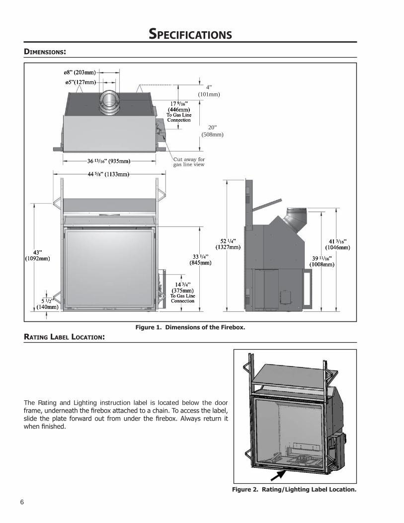
4”(101mm)
20”(508mm)
Rating LabeL Location:
SPECIFICATIONSDimensions:
Figure 1. Dimensions of the Firebox.
The Rating and Lighting instruction label is located below the door frame, underneath the firebox attached to a chain. To access the label, slide the plate forward out from under the firebox. Always return it when finished.
Figure 2. Rating/Lighting Label Location.

7
SPECIFICATIONSRating LabeL:
Figure 3. Rating Label.
ELECTRICAL RATING:(EXIGENCES ÉLECTRIQUES) Fan type circulator (Ventilateur circulaire): 120V AC 60hz/ Less than 7AmpMINIMUM FRAMING DIMENSIONS (DIMENSIONS D’ENCADREMENT MINIMALES): Depth (Profond) 24” (610mm), Width (Largeur) 44.625“ (114cm), Height to header (Hauteur de tête) 52.25” (133cm), Interior Ceiling (Plafond l'Intérieur) 80“ (203cm)CLEARANCES TO COMBUSTIBLES: (DISTANCE OBLIGATOIRE DES COMBUSTIBLES) : Fireplace frame to side wall (Du frome de la cheminée au mur latéral): 10" (25.5 cm), Unit base to 10” mantel (Base de l'unité de Mantel) 52.25" (133cm)
VENT PIPE CLEARANCES:(ESPACES LIBRES DE VENTILATION) See manufacturer’s listing, label and installation instructions. Verifeez l’identifaction, l’etiquette et les instructionsd’installation du fabricant. This appliance must be properly connected to a venting system in accordance with the manufacturer's installation instructions. Cet appareil doit être convenablement connecté à un système donner vent conformément aux instructions d'installation du fabricant. VENTED GAS FIREPLACE HEATER - NOT FOR USE WITH SOLID FUELS. MAY BE INSTALLED IN BEDROOM OR BEDSITTING ROOM (IN CANADA with a listed wall thermostat). THIS APPLIANCE MUST BE PROPERLY CONNECTED TO A VENTING SYSTEM IN ACCORDANCE WITH THE MANUFACTURER'S INSTALLATION INSTRUCTIONS. FOR DIRECT DISCHARGE WITHOUT DUCT CONNECTION. This appliance must be installed as per manufacturers installation instructions and in accordance with local codes if any. If none exist, use current installation code CAN/CSA B149.1 in Canada or ANSI Z223.1/NFPA 54 in the USA. This vented gas fireplace is not for use with air filters. FOR USE WITH GLASS DOORS CERTIFIED WITH THE APPLIANCE ONLY. This appliance is only for use with the type(s) of gas indicated on the rating plate. A conversion kit is available for this appliance. This appliance is not convertible for use with other gases, unless a certified kit is used. Sections of the venting system have not been installed. WARNING: Do not operate the appliance until all sections have been assembled and installed in accordance with the manufacturers instructions.FOYER AU GAZ A EVACUATION - NE PAS EMPLOYER AVEC DES COMBUSTIBLES SOLIDES. Cet appareil peut être installé dans une chambre à coucher ou un studio. Cet appareil doit être branché correctement à un système de conduits. Uniquement pour l'échappement direct sans raccord de conduit.Cet appareil doit être installé selon les directives d'installation du manufacturier et selon les codes locaux, s'il y a lieu. Autrement, employez le code d'installation en vigueur au Canada CAN/CSA B149.1. Ne pas utilliser de filtre a air avec ce foyer au gaz a evacuation. POUR L'USAGE AVEC PORTES VITREES A CERTIFIE AVEC L'APPAREIL SEULEMENT. Cet apperareil doit etre utilise uniquement avec le type de gaz indique sur la plaque. Cet appareil ne peut etre converti a d’autres gaz sauf si une trouse de conversion certifee est utilisee. ADVERTISSEMENT: Ne pas utiliser l’appareil tant que toutes les sections n’ont pas ete assemblees et installees selon les instructions du fabricant.MOBILE HOME: May be installed in an aftermarket, permanently located, manufactured home (USA only) or mobile home, where not prohibited by local codes. See owner's manual for details. This appliance must be installed in accordance with the current Standard for Mobile Homes, CAN/CSA Z240, or the Manufactured Home Construction and Safety Standard, Title 24 CFR, Part 3280, or when such standard is not applicable, the current Standard for Fire Safety Criteria for Manufactured Home Installations, sites, and Communitties, ANSI/NFPA 501A. LA MAISON MOBILE : Peut être installé dans une maison mobile. Cet appareil doit être installé conformement aux Normes actuelles pour Maisons Mobiles, le BOITE/CSA Z240, ou les Normes de Construction et de Sureté des Maisons Pré-fabriquées (Titre 24 CFR, la Partie 3280). Quand ces Normes ne sont pas en vigueur, il faut suivre les criteres pour la sureté (contre les increndies) et pour la construction des Maisons Pré-fabriquées, leurs sites, ANSI/NFPA 501A, et des communautées aux Instructions du manufacturier.MANUFACTURED BY (FABRIQUE PAR) : SHERWOOD INDUSTRIES LTD. 6782 OLDFIELD RD. SAANICHTON, BC, CANADA
WH- Q4VENTED GAS FIREPLACE HEATER ENVIRO MODEL: FOYER AU GAZ A EVACUATION MODELE ENVIRO:
CONFORMS TO / CONFORME: ANSI Z21.88-2014/CSA 2.33-2014, CERTIFIED TO / Agréé: CSA 2.33-2014 VENTED GAS FIREPLACE HEATERS / FOYER AU GAZ EVACUATION; CAN/CGA 2.17-M91 GAS FIRED APPLIANCES FOR HIGH ALTITUDES / LES APPAREILSBRULANT GAZ POUR UTILISATION EN HAUTES ALTITUDES
INPUT (ENTRÉE): NAT: 0-4500 FT (1372 M) LPG: 0-4500 FT (1372 M) MAX: 48,000 BTU (14.07 KW•h) MAX: 48,000 BTU (14.07 KW•h) MIN: 16,000 BTU (4.68 KW•h) MIN: 17,000 BTU (4.98 KW•h)
MANIFOLD PRESSURE (PRESSION D’ADMISSION): NAT: 3.5 in. WC (0.87kPa) / 1.6 in. WC (0.40kPa) LPG: 10 in. WC (2.48kPa) / 6.4 in. WC (1.59kPa)MINIMUM GAS SUPPLY PRESSURE: (PRESSION MINIMALE D'ALIMENTATION DE GAZ PERMISE) NAT: 5 in. Wc (1.24kPa) LPG: 12 in. Wc (2.98kPa)ORIFICE SIZE: (DIMENSIONS DE L’ORIFICE) NAT: Left # 45 DMS, Right # 41 DMS LPG: Left # 55 DMS, Right # 53 DMSPILOT ORIFICE SIZE: (DIMENSIONS DE PILOTER L’ORIFICE)
NAT: (Gaz naturel) LPG (Propane)
CAUTION: Hot while in operation. Do not touch. Keep children, clothing, furniture, or gasoline and other liquids having flammable vapors away. ATTENTION: Très chaud quand allumé. Ne touchez pas, les brûlures sévères peuvent résulter.
Tenez loin des enfants, des vêtements, des meubles,de l’essence ou d’autres fluides produisant des vapeurs inflammables. DATE OF MANUFACTURE: DATE DE FABRICATION:
J F M A M J J A S O N D 2015 2016 2017 2018
DO NOT REMOVE THIS LABEL / N'ENLEVEZ PAS CETTE ETIQUETTE
Q4Certified for use in Canada & USA
Certifié pour installation au Canada et aux Etats-Unis.
3151093
C-14447
NAT: # 62 DMS LPG: Left # 35 DMS

8
INSTALLATION SET�UPDooR RemovaL anD instaLLation:
1) The fireplace door is hung on two (2) hooks on the top of the firebox. The two (2) door latches at the bottom of the firebox hook over the tabs on the bottom of the door frame.
2) Lower the door latch tool underneath the door frame. Catch the lower door latch with the door latch tool (see Figure 5) and pull it out slightly, then down. Once the lower door latch clears the tab on the bottom of the door frame, release it inwards and then remove the door latch tool. Refer to Figures 6 & 7.
3) Pull the Door Frame at the bottom forward about 2” (5cm), then lift the Door Frame upwards to clear the Upper Door
Large hooked end forremoving the door.
Small hooked end isfor Air Shutters
Adjustment Levers.
Figure 4: Door Latch /Air Adjustment Tool.
Lower Door Latches
Door Frame
Upper Door Hooks
Figure 6: Door Latch Tool in Place. Figure 5: Door Latch Locations.
Hooks. Refer to Figures 7 & 8.
4) Lift the Door Frame away, being careful that the glass panel is secure within the Door Frame.
Figure 8: Top Door Hook. Figure 7: Door Latch Locations.
FiRebox LineR instaLLation:
IMPORTANT: The paint on the panels may fade for the first 8-10 hours of burn time, but will come back to its color after the paint has cured. The paint is very delicate and handing them with care is necessary not to mark or smudge the paint.

9
Figure 9: Rear Brick Panel Support.
Rear BrickPanel Support
(in lower position)
INSTALLATION SET�UP
Figure 10: Rear Firebox Liner Panel in Place.
Figure 11: Left Firebox Liner Panel on Front Edge of Firebox. Figure 12: Left Firebox Liner Panel in Place.
Figure 13: Top Firebox Liner Panel in Place. Figure 14: Right Firebox Liner Panel in Place.
1. Prior to installing the firebox liners, you will need to ensure the Rear Brick Panel Support is in the correct position. The support is located at the back of the firebox (see Figure 9) and can be installed in two (2) positions. The upper position (using the lower screw holes) is for the October Panels. The lower position (using the upper screw holes) is for the Sandstone, Ledgestone, and Porcelain Panels. Remove the Support, if necessary, and move it to
5. Install the Top Panel by placing it on top of the Rear Panel and behind the Left Panel (see Figure 13). Hold it with one hand or have someone else hold it for you while you place the last panel. WARNING: If this panel falls from this location it will possibly break or the paint work will become chipped.
6. Place the Right Firebox Liner Panel in the same manner used for the Left Panel (see
Figure 14). The vertical edges of the left and right panels should line up with the front edges of the firebox sides. The side panels rest up against the back panel and hold the top panel in position.
the appropriate placement.
2. Ensure the light covers provided with your kit are installed on the Light Cover Bases at the rear of the firebox. The tabs on the back of the Light Cover slide down behind the light cover base. Refer to Figures 44 and 45.
3. Install the Rear Firebox Liner. This panel fits around the accent lights and rests on top of the Rear Brick Panel Support. It will stay in this location as you install the remaining panels. Refer to Figure 10.
4. Install the Left Firebox Liner Panel; it sits on the bottom front edge of the firebox (see Figure 11 & 12), a support bracket at the lower rear of the firebox, and is held in by a retainer at the top of the firebox. Adjust the panel retainers as required.

10
INSTALLATION SET�UPLog buRneR / embeR beD instaLLation:
1. Use the two (2) T-20 screws provided; install the rear burner shield onto the back of the burner. The mounting holes are just above the mixing tubes at the rear of the burner, refer to Figure 15.
Figure 15: Installing Rear Burner Shield.
Burner MountingBrackets
Pilot Assembly
Figure 16: Burner Mounting Brackets.
Figure 17: Log Burner Over Pilot Assembly.
2. In the bottom rear of the firebox there are two (2) gas orifices in a housing that facilitate the air shutter mechanisms and the Burner Mounting Brackets are above them (See Figure 16). There are two (2) mixing tubes underneath the back of the burner (see Figure 15). Lift the burner into the firebox with the back of the burner tilted downward. Keep the burner high enough at the front to clear the pilot assembly. Line up the mixing tubes with the holes in the burner mounting brackets and slowly lower the front of the burner over the pilot assembly (see Figure 17).
Pull up to Angular Brackets
Figure 18: Log Burner in Place.
Figure 19: Burner Accents Pieces in Place.
3. Pull the burner forward up to the angular brackets near the front of the firebox (see Figure 18).
IMPORTANT: If the burner is not far enough back to lower the burner behind these brackets, then the mixing tubes are not engaged in the air shutter. Failing to ensure the mixing tubes are located in the mixing tube support brackets may cause serious performance and or safety issues.
Mixing Tubes

11
INSTALLATION SET�UP
Grate Tab
Figure 21: Tab on Firebox Grate.
Slot
Figure 20: Slot for Firebox Grate.
4. Install the burner accent pieces as shown in Figure 19. There are a left, a right and a front ceramic trim. On each side of the burner and on the inside of each burner side accent pieces there is a slot, which should be aligned in order to position the log grate correctly (see Figure 18).
5. The firebox grate has two (2) tabs that run below the feet of the grate (see Figure 21), place the grate over the burner top and carefully inserting the grate tabs into the slots on the burner (see Figure 20 & 22). Once the grate is installed correctly, the burner, grate, and side burner accents will be all locked together.
Figure 22: Firebox Grate in Place.
Log set instaLLation:
IMPORTANT: The paint on the logs may fade for the first 8-10 hours of burn time, but will come back to its color after the paint has curred. The paint is very delicate and handing them with care is nessesary not to mark or smuge the paint.
1. Install Right Rear Log. The right side sits on the grate with the groove on the bottom of the log fitting onto the top of the grate (see Figure 23). Insert the log pin into the top of the ember burner (see A in Figure 23). Align the log front edge with the front section of the grate (see B in Figure 23).
Figure 23: Log 1 in Place.
A B
1 C2
D
Figure 24: Log 2 in Place.

12
3
Figure 25: Log 3 in Place.
4
Figure 26: Log 4 in Place.
2. Install Left Rear log with the right side on the grate, using a groove on the bottom of the log to index itself to the grate (see Figure 24). The right side self locates on the first log. Alignment notches are provided for locating the centre area (see C in Figure 24). Align the front edge of the log with the upright section of the log grate (see D in Figure 24).
3. Insert Log 3 into the groove on the burner top. The groove has a stop at the rear to position the log properly from front to back. Refer to Figure 25.
4. Log 4 sits in a groove molded into the top of the burner top. See the details in Figure 26 showing the indexing key on this log.
5
Figure 27: Log 5 in Place.
6. Install Log 6 by resting it across the flat section of Log 5 and locating the front edge across the grate finger as shown in Figure 28.
7. Log 7 sits in between the left panel and the left grate finger and cross the bar of the grate (see Figure 29). There is a notch across Log 2, which this log will locate into. The edge along the back of this log will index into the notch of Log 2.
6
Figure 28: Log 6 in Place.
7
Figure 29: Log 7 in Place.
INSTALLATION SET�UP
5. Install Log 5 with the right side resting on the grate and the right side right up against the right hand firebox liner. The left side sits on a flat section in Log 3. Refer to Figure 27.

13
INSTALLATION SET�UP
8
Figure 30: Log 8 in Place.
9
Figure 31: Log 9 in Place.
8. Situate Log 8 between the right grate finger, the right firebox liner and the grate cross bar (see Figure 30). On the back of the log near the top end is a ceramic pin, this pin sits into a groove on the top of Log 2.
9. Sit the Y shaped Log 9 across Log 4 and 5 as shown in Figure 31.
10. The final little Accent Twig sits on the front ceramic burner accent and the grate finger as shown in Figure 32.
NOTE: Variances in gas quality or log placement may cause some discoloration of the log set to occur.
10
Figure 32: Accent Twig in Place.

14
2. Ensure the Rear Brick Panel Support is in the lower position. The support is located at the back of the firebox (see Figure 10). Remove the Support, if necessary, and move it to the appropriate placement.
3. Install the Rear Firebox Liner. This panel rests on top of the accent lights and Rear Brick Panel Support. It will stay in this location as you install the remaining panels. Refer to Figure 35.
PoRceLain PaneL Kit instaLLation:
1. Install the porcelain Light Covers over the Light Cover Base. The tabs on the back of the Light Cover slide down behind the Light Cover Base. Refer to Figures 33 & 34.
Figure 33: Porcelain Light Covers in Place. Figure 34: Porcelain Light Covers Close-up.
INSTALLATION SET�UP
Figure 35: Rear & Left Porcelain Panels in Place.
Figure 36: Top Porcelain Panel in Place.
4. Install the Left Firebox Liner Panel; it sits on the bottom front edge of the firebox (see Figure 35), a support bracket at the lower rear of the firebox, and is held in by a retainer at the top of the firebox. Adjust the panel retainers as required.
5. Install the Top Panel by placing it on top of the Rear Panel and behind the Left Panel (see Figure 36). Hold it with one hand or have someone else hold it for you while you place the last panel. WARNING: If this panel falls from this location it will possibly break or the paint work will become chipped.
6. Place the Right Firebox Liner Panel in the same manner used for the Left Panel. The vertical edges of the left and right panels should line up with the front edges of the firebox sides. The side panels rest up against the back panel and hold the top panel in position.

15
START�UP & OPERATIONnoRmaL sounDs DuRing oPeRation:
Table 1: Normal Sounds
Component Sound & ReasonQ4 & Fascia Creaking when heating up or cooling down.
Burner Light pop or poof when turned off; this is more common with LP units.
Pilot Flame Quiet whisper while the pilot flame in on.
Gas Control Valve Dull click when turning on or off, this is the valve opening and closing.
Remote contRoL oPeRations:
The Proflame GTMF is a modular remote control system that directs the functions of the Q4. The Proflame GTMF is configured to control the on/off main burner operation, its flame levels and provides on/off and Smart thermostatic control of the appliance. The system controls a remotely actuated 120V/60Hz power outlet, fan speed through six (6) levels and has a constantly powered 120V/60Hz power outlet.
WARNING
THE TRANSMITTER AND RECEIVER ARE RADIO FREQUENCE DEVICES. PLACING THE RECEIVER IN OR NEAR METAL MAY SEVERELY REDUCE THE SIGNAL RANGE.
ATTENTION!
- TURN “OFF” THE MAIN GAS SUPPLY OF THE APPLIANCE DURING INSTALLATION OR MAINTENANCE OF THE RECEIVER.
- PLACE THE RECEIVER’S 3 POSITION SLIDER SWITCH IN THE “OFF” POSITION DURING INSTALLATION OR MAINTENANCE.
- TURN “OFF” MAIN GAS SUPPLY TO THE APPLIANCE PRIOR TO REMOVING OR REINSERTING THE BATTERIES IN THE RECEIVER.
- DURING APPLIANCE INSTALLATION/MAINTENANCE OR IN CASE OF REMOTE CONTROL MALFUNCTION TURN OFF THE FAN CONTROL MODULE USING THE “ON/OFF” MAIN POWER SWITCH ON THE FRONT PANEL OF THE FCM.
technicaL Data
Transmitter (Remote Control):Supply voltage 4.5 V (three 1.5 V AAA batteries)Ambient temperature ratings 0 - 50 °C (32 - 122 °F)
Receiver:Supply voltage 6.0 V (four 1.5 V AA batteries)
Fan Control Module:Supply voltage/frequency: 120 V / 60 HzAux switched output: 120 V / 60 Hz / 2 AFan speed output: 120 V / 60 Hz / 1 Art
system DescRiPtion:
The Proflame 2 Remote Control System consists of two (2) elements:1. Proflame 2 Transmitter.2. Integrated Fireplace Controller (IFC) and a wiring harness to connect the Receiver to the gas valve, stepper
motor and Fan Control Module.

16
Figure 38: Proflame 2 Transmitter LCD Screen.
CPI Mode
OPERATING INSTRUCTIONS
tRansmitteR:
The Proflame 2 Transmitter is a remote control with a blue backlit lcd display. It uses a streamline design with a simple button layout and informative lcd readout (Figure 37). The Transmitter is powered by three (3) AAA type batteries. A Mode Key is provided to Index between the features and a Thermostat Key is used to turn on/off or index through Thermostat functions (Figure 37 & 38)
Figure 37: Proflame 2 Transmitter.
Blue LCD display
UP/DOWN Arrow Key
ON/OFF KeyTHERMOSTAT Key
MODE Key

17
The Battery Holder (Figure 39) connects directly to the IFC with a wiring harness. The IFC is powered by four (4) AA type batteries. The IFC accepts commands via radio frequency from the Transmitter to operate the appliance in accordance with the particular Proflame system configuration. The Battery Holder has a three (3) position slider switch that can be set to one of three positions: ON (Manual Override), Remote (Remote control), or Off. The Battery Holder has a reset button at the front right corner that is used is to synchronize the Transmitter when using the for the first time, or after the batteries have been replaced.
batteRy hoLDeR:
Figure 39: Battery Holder.
Reset Button
OPERATING INSTRUCTIONS
oPeRating PRoceDuRe:
Initializing The System For The First Time
Install the four (4) AA batteries into the IFC battery holder. Note the polarity of the battery and insert into the battery bay as indicated on the body of the battery holder. Press the reset button on the Battery Holder marked “PRG” (see Figure 39).
The IFC will “beep” three (3) times to indicate that it is ready to synchronize with a Transmitter. Install the three (3) AAA type batteries in the Transmitter battery bay, located on the base of the Transmitter. With the batteries already installed in the Transmitter, push the ‘ON’ button. The IFC will “beep” four (4) times to indicate the Transmitter’s command is accepted and sets to the particular code of that Transmitter. The system is now initialized.
Temperature Indication Display
With the system in the “OFF” position, press the Thermostat Key and the Mode Key at the same time. Look at the LCD screen on the transmitter to verify that a °C or °F is visible to the right of the Room Temperature display (see Figure 39).
Turn on the AppliancePress the ON/OFF Key on the Transmitter. The Transmitter display will show all active Icons on the screen. A single “beep” from the Receiver will confirm reception of the command and will commence to first ignite the pilot light, followed by the main burner. This should take about 10 seconds to complete.
Figure 40: Remote Control Display in Farenheit and Celcius.

18
switching to continuous PiLot moDe:
When the Q4 is turned off press the mode key to index to the constant pilot (CPI) mode icon (see figure 41). Pressing the up arrow key will select Continuous Pilot Ignition (CPI) and pressing the down arrow key will return to IPI. Once a selection is made the IFC will beep once to confirm it had received the command. NOTE: It is recommended to use the continuous pilot mode during the winter when the outside temperature is below 50°F (10°C) to keep the chimney properly heated for updraft during burner ignition. Continuous pilot mode also keeps the firebox warm which eliminates both heat loss to cold air that is trapped inside the firebox as well as excessive exhaust vapour condensation on the door glass.
Figure 41: CPI Pilot Mode.
Turn off the AppliancePress the ON/OFF Key on the Transmitter. The Transmitter LCD display will only show the room temperature and Icon (see Figure 42). A single “beep” from the IFC confirms reception of the command and both the pilot light (if the unit is not set to continuous pilot) and main burner will turn off.
Room Thermostat (Transmitter Operation)The Remote Control can operate as a room thermostat. The thermostat can be set to a desired temperature to control the comfort level in a room. To activate this function, press the Thermostat Key (see Figure 37). The LCD display on the Transmitter will change to show that the room thermostat is “ON” and the set temperature is now displayed (see Figure 42). To adjust the set temperature, press the Up or Down Arrow Keys until the desired set temperature is displayed on the LCD screen of the Transmitter.
Smart Thermostat (Transmitter Operation) The Smart Thermostat function adjusts the flame height in accordance to the difference between the set point temperature and the actual room temperatures. As the room temperature gets closer to the set point the Smart Function will modulate the flame down. To activate this function, press the Thermostat Key (Figure 37) until the word “SMART” appears to the right of the temperature bulb graphic (Figure 43). To adjust the set temperature, press the Up or Down Arrow Keys until the desired set temperature is displayed on the LCD screen of the Transmitter.
Room Temperature
Set Temperature
Thermostat ON
Figure 42: Remote Control Displays Set Temperature.
Figure 43: Remote Control’s Smart Flame Function.
OPERATING INSTRUCTIONS

19
Remote Flame Control The Proflame 2 GTMF has six (6) flame levels. With the system on, and the flame level at the maximum in the appliance, pressing the Down Arrow Key once will reduce the flame height by one step until the flame is turned off. The Up Arrow Key will increase the flame height each time it is pressed. If the Up Arrow Key is pressed while the system is on but the flame is off, the flame will come on in the high position (refer to Figure 44). A single “beep” will confirm reception of the command.
Figure 44: Remote Control’s Flame Levels.
Flame Off Flame Level 1
Flame Level 5 Maximum Flame Level
OPERATING INSTRUCTIONS
Figure 46: Remote Control with Aux (not used)
Key lockThis function will lock the keys to avoid unsupervised operation. To activate this function, press the MODE and UP keys at the same time and the a lock will appear (see Figure 47). To de-activate this function, press the MODE and UP Keys at the same time.
Low Battery Power DetectionTransmitter: The life span of the remote controlbatteries depends on various factors: quality ofthe batteries used, the number of ignitions ofthe appliance, the number of changes to theroom thermostat set point, etc. When theTransmitter batteries are low, a Battery Icon willappear on the LCD display of the Transmitter(see Figure 48) before all battery power is lost.When the batteries are replaced this Icon willdisappear.
Fan ControlThe Q4 comes with a convection fan that can be controlled with the Transmitter. The fan speed can be adjusted thorugh six (6) speeds. To control the fan press the MODE key (Figure 37) to index to the fan control icon (Figure 45). Use the UP/DOWN arrow keys to turn on, off, or adjust the fan speed (Figure 44). A single beep from the IFC will confirm the command has been received
Figure 45: Fan Control

20
WARNING: Fire Hazard. Can cause severe injury or death The Receiver causes ignition of the appliance. The appliance can turn on suddenly. Keep away from the appliance burner when operating the remote system or activating manual by pass of the remote system.
WARNING: Shock Hazard. Can cause severe injury or death. This device is powered by line voltage. Do not try to repair this device. In no way is the enclosure to be tampered with or opened. Disconnect from line voltage before performing any maintenance.
WARNING: Devices rated more than 5A shall not be connected to the OUT receptacle. Devices rated more than 1A shall not be connected to the FAN receptacle. Devices rated more than 2A shall not be connected to the AUX receptacle.
CAUTION: Property Damage Hazard. Excessive heat can cause property damage. The appliance can stay lit for many hours. Turn off the appliance if it is not going to be attended for any length of time. Always place the Transmitter where children cannot reach it.
OPERATING INSTRUCTIONS
waLL mounting the ReceiveR:
The receiver can be placed inside a standard Junction type wall box either by itself or in combination with a light dimmer control. This installation can take place up to 8’ft (2.4m) from the appliance control valve.
1. Connect the wiring harness to the back of the Receiver.
2. Install the Receiver in the Junction box using the existing J box screws (Figure 39).
3. Insert the four (4) AA type batteries in the battery compartment with the correct polarity.
4. Place the slider into the cover plate.
5. Put the Receiver switch in the “OFF” position.
6. Make sure the Receiver and cover plate words “ON” and “UP” are on the same side.
7. Align the slider with the switch on the Receiver and couple the switch into the slider.
8. Align the screw holes.
9. Using the two (2) screws provided secure the cover plate to the Receiver.is now displayed (see Figure 41). To adjust the set temperature, press the Up or Down Arrow Keys until the desired set temperature is displayed on the LCD screen of the Transmitter.
IFC: The life span of the IFC batteries depends on various factors during a prolonged power outage: quality of the batteries used, the number of ignitions of the appliance, the number of changes to the room thermostat set point etc. When the IFC batteries are low, No “beep” will be emitted when it receives an On/Off command from the Transmitter. This is an alert for a low battery condition for the IFC. When the batteries are replaced the “beep” will be emitted from the Receiver when the ON/OFF Key is pressed (See InItIalIzIng the SyStem for the fIrSt tIme).
Figure 47: Remote Control Locked.
Figure 48: Low Battery Indicator.

21
START�UP & OPERATIONchecK FoR PRoPeR buRneR FLame
Once your new Q4 has run through the “first fire”, (see section on first firing) check for proper flame appearance. A gas appliance’s performance is dependent on several factors. Vent configuration, fuel type, altitude and restrictor setting are all factors in how the final flame appears in the firebox. The fireplace must be operated for a minimum of 30 minutes or the flame will not normalize. Once this is done, the flame should look similar to Figure 49. The flame should be lit at all ports, and be burning directly from the burner surface. The base should show some blue with a bright yellow appearance above. The flame should be lively without being disturbed by excessive air turbulence. If your flame does not resemble these images below, ask your service technician to review this installation to determine what adjustments may be required. Figure 49: Proper Burner Flame for Ember Bed/ Log
Burner.aiR shutteR aDjustment:
The Q4 is setup to work with two (2) gas orifices. The orifice on the left (looking from the front) feeds the front burner while the right feeds the rear burner, which can also be switched off using the remote control.
Each orifice has its own Air Shutter. The Air Shutter is connected to an Adjustment Lever that is accessible from the front and bottom of the firebox. These Air Shutters can be adjusted during the operation of the fireplace.
This Figure 68 shows the fireplace with the door and the burners removed. This is to better show the Air Shutters and the Adjustment Levers. The Door/Air Shutter Tool (see Figure 4) has a small hook on one end. This hook can be used by placing it into the hole at the end of each Adjustment Lever and moving the Adjustment Lever forward or rearward. Moving the Lever towards you opens the Air Shutter, while moving it rearward, closes the Air Shutter.
Air shutters should be adjusted so that the gas flame burns with a blue base and a bright yellow upper section. Air shutters set to closed will lead to a dirty flame which may lead to soot gathering on the logs and/or glass panel. Properly set Air Shutters will result in a very blue flame for the first fifteen (15) minutes of operations with the flame becoming more yellow as the unit comes up to operating temperature.
Figure 48: Air Shutter Adjustment.
Left Right
Glass / Media BurnerLP Open Open
NG Open Open
Log Set/ Ember Bed BurnerLP Open ⅛” (3mm) Open
NG Open 1/16” (2mm) Open

22
The safety screen included with this stove can be removed for cleaning. Removal and re-installation is show in the steps below.
Warning: The safety screen becomes hot when the unit is operating; ensure that the unit is turned off, and that it has cooled to room temperature before begining this installation.
SAFETY SCREEN & CLEANING
Figure 50: Safety Screen Removal
Re-instaLLaion:1. Lift the face upright in front of the
fireplace with the four (4) hooks pointing towards the fireplace. Slide the hooks into the corresponding brackets on each side of the cabinet (see Figure 51). Ensure the hooks are secure before releasing the safety screen.
Figure 51: Installing Safety Screen onto Cabinet Bracket (Parts removed for clarity)
RemovaL:1. Firmly grip the safety screen with from both sides and gently lift screen off the mounting
brackets and pull back (see Figure 50).
2. Place the screen gently out of the way and clean stove as needed.
22

23
SERVICE ⁄ MAINTENANCELighting instRuction LabeL:
Figure 52. Lighting Label.
CAUTION:Hot while operating. Do not touch. Severe burns may result. Keep children, clothing, furniture, gasoline or other flammable vapors away.
CAUTION: Do not operate this fireplace with the glass removed, cracked or broken. Replacement of the panel(s) should be done by a licensed or qualified person! This appliance needs fresh air for safe operation and must be installed with provisions for combustion and ventilation air. See installation and operating instructions manual. Keep burner and control compartment clean.WARNING: Improper installation, adjustment, alteration, service or maintenance can cause injury or property damage, or loss of life. Refer to owner's manual provided with this appliance. See installation and operating instructions accompanying appliance. Installation and service must be performed by a qualified installer, service agency, or the gas supplier.
WARNING: IF YOU DO NOT FOLLOW THESE INSTRUCTIONS EXACTLY, A FIRE OR EXPLOSION MAY RESULT CAUSING PROPERTY DAMAGE, PERSONAL INJURY OR LOSS OF LIFE.
A) This appliance is equipped with an ignition device which automatically lights the pilot. Do not try to light the pilot by hand. B) BEFORE LIGHTING smell all around the appliance area for gas and next to the floor because some gas is heavier than air and will settle on the floor. WHAT TO DO IF YOU SMELL GAS: Do not try to light any appliance. Do not touch any electrical switch: do not use any phone in your building. Immediately call your gas supplier from a neighbors' phone. Follow the gas suppliers instructions. If you cannot reach your gas supplier, call the fire department.
C) If any portion of this appliance does not operate as the instructions indicate, don't try to repair it, call a qualified service technician. Do not use tools. Force or attempted repair may result in a fire or explosion.
D) Do not use this appliance if any part has been under water. Immediately call a qualified service technician to inspect the appliance and to replace any part of the control system and any gas control which has been under water.
OPERATING INSTRUCTIONS
1. STOP! Read the safety information above on this label.
2. Read the owner's manual including the section on "Remote Control" operation.
3. Do not attempt to light the pilot by hand.
4. If you smell gas, STOP! Follow "B" in the safety information above on this label. If you don't smell gas, go to the next step.
5. Using the remote control, set thermostat to desired setting, or switch press the ON/OFF key on the remote. "ON" will be indicated on the display of the remote and an audible "beep" will be heard at the unit to idicate the command has been received.
TO TURN OFF GAS TO APPLIANCE1. Set thermostat to lowest setting, or press the ON/OFF Key. "OFF" will be indicated on the display and an audible "Beep" will be heard at the unit to indicate the command has been received.
FOR YOUR SAFETY READ BEFORE OPERATING
C-11800
6. This appliance is equipped with a completely automatic ignition and lighting control. The control will attempt to light the pilot several timesif necessary. If it is unsuccessful, it will discontinue operations. If the appliance does not operate, follow the instructions "To Turn Off Gas To Appliance" and call your service technician or gas supplier.
Blue LCD Display
THERMOSTAT KeyON/OFF Key
UP/DOWN Arrow KeyMODE Key
ELECTRICAL RATING:(EXIGENCES ÉLECTRIQUES)Fan type circulator (Ventilateur circulaire) : 120 volts AC 60 hz / Less than 7 Amperes CLEARANCES TO COMBUSTIBLES: (DISTANCE OBLIGATOIRE DES COMBUSTIBLES) Stove side (Côté de poêle): 4 inches (10.2cm), Back (Arriére): 4 inches (10.2cm), Ceiling from bottom of unit (Du fond d'unité au Plafond): 80” inches (203.2cm), From fireplace frame to side wall (Du frome de la cheminée au mur latéral): 10" (25.5 cm), From base of the unit to shelf, header, or 12" (30.5cm) mantel (De la base de l'unité à une étagère, un en-tête, ou un 12" manteau de cheminée): 52.25" (133cm)VENT PIPE CLEARANCES:(ESPACES LIBRES DE VENTILATION) See manufacturer’s listing, label and installation instructions. Verifeez l’identifaction, l’etiquette et les instructionsd’installation du fabricant. This appliance must be properly connected to a venting system in accordance with the manufacturer's installation instructions. Cet appareil doit être convenablement connecté à un système donner vent conformément aux instructions d'installation du fabricant. VENTED GAS FIREPLACE HEATER - NOT FOR USE WITH SOLID FUELS. MAY BE INSTALLED IN BEDROOM OR BEDSITTING ROOM (IN CANADA with a listed wall thermostat). THIS APPLIANCE MUST BE PROPERLY CONNECTED TO A VENTING SYSTEM. ONLY FOR DIRECT DISCHARGE WITHOUT DUCT CONNECTION. This appliance must be installed as per manufacturers installation instructions and in accordance with local codes if any. If none exist, use current installation code CAN/CSA B149.1 in Canada or ANSI Z223.1/NFPA 54 in the USA. This vented gas fireplace is not for use with air filters. FOR USE WITH GLASS DOORS CERTIFIED WITH THE APPLIANCE ONLY. This appliance is only for use with the type(s) of gas indicated on the rating plate. A conversion kit is available for this appliance. This appliance is not convertible for use with other gases, unless a certified kit is used. Sections of the venting system have not been installed. WARNING: Do not operate the appliance until all sections have been assembled and installed in accordance with the manufacturers instructions.FOYER AU GAZ A EVACUATION - NE PAS EMPLOYER AVEC DES COMBUSTIBLES SOLIDES. Cet appareil peut être installé dans une chambre à coucher ou un studio. Cet appareil doit être branché correctement à un système de conduits. Uniquement pour l'échappement direct sans raccord de conduit.Cet appareil doit être installé selon les directives d'installation du manufacturier et selon les codes locaux, s'il y a lieu. Autrement, employez le code d'installation en vigueur au Canada CAN/CSA B149.1. Ne pas utilliser de filtre a air avec ce foyer au gaz a evacuation. POUR L'USAGE AVEC PORTES VITREES A CERTIFIE AVEC L'APPAREIL SEULEMENT. Cet apperareil doit etre utilise uniquement avec le type de gaz indique sur la plaque. Cet appareil ne peut etre converti a d’autres gaz sauf si une trouse de conversion certifee est utilisee. ADVERTISSEMENT: Ne pas utiliser l’appareil tant que toutes les sections n’ont pas ete assemblees et installees selon les instructions du fabricant.MOBILE HOME: May be installed in an aftermarket, permanently located, manufactured home (USA only) or mobile home, where not prohibited by local codes. See owner's manual for details. This appliance must be installed in accordance with the current Standard for Mobile Homes, CAN/CSA Z240, or the Manufactured Home Construction and Safety Standard, Title 24 CFR, Part 3280, or when such standard is not applicable, the current Standard for Fire Safety Criteria for Manufactured Home Installations, sites, and Communitties, ANSI/NFPA 501A. LA MAISON MOBILE : Peut être installé dans une maison mobile. Cet appareil doit être installé conformement aux Normes actuelles pour Maisons Mobiles, le BOITE/CSA Z240, ou les Normes de Construction et de Sureté des Maisons Pré-fabriquées (Titre 24 CFR, la Partie 3280). Quand ces Normes ne sont pas en vigueur, il faut suivre les criteres pour la sureté (contre les increndies) et pour la construction des Maisons Pré-fabriquées, leurs sites, ANSI/NFPA 501A, et des communautées aux Instructions du manufacturier.MANUFACTURED BY (FABRIQUE PAR) : SHERWOOD INDUSTRIES LTD. 6782 OLDFIELD RD. SAANICHTON, BC, CANADA
WH- DV48VENTED GAS FIREPLACE HEATER ENVIRO MODEL: FOYER AU GAZ A EVACUATION MODELE ENVIRO:
TESTED TO / TESTÉE SELON LES NORMES: ANSI Z21.88a-2007/CSA 2.33a-2007 VENTED GAS FIREPLACE HEATERS / FOYER AU GAZ EVACUATION; CAN/CGA 2.17-M91 GAS FIRED APPLIANCES FOR HIGH ALTITUDES / LES APPAREILS BRULANT GAZ POUR UTILISATION EN HAUTES ALTITUDES; Can/CSA P.4.1-02 (R2006) TESTING METHOD FOR MEASURING ANNUAL FIREPLACE EFFICIENCY / LA METHODE D'ESSAI POUR MESURER L'EFFICACITE DE CHEMINEE ANNUELLE.
INPUT (ENTRÉE): NAT: 0-4500 FT (1372 M) MAX: 48,000 BTU (14.07 KW•h) MIN: 16,000 BTU (4.68 KW•h) LPG: 0-4500 FT (1372 M) MAX: 48,000 BTU (14.07 KW•h) MIN: 17,000 BTU (4.98 KW•h)MANIFOLD PRESSURE (PRESSION D’ADMISSION): NAT: 3.5 in. WC (0.87kPa) / 1.6 in. WC (0.40kPa) LPG: 10 in. WC (2.48kPa) / 6.4 in. WC (1.59kPa)MINIMUM GAS SUPPLY PRESSURE: (PRESSION MINIMALE D'ALIMENTATION DE GAZ PERMISE) NAT: 5 in. Wc (1.24kPa) LPG: 12 in. Wc (2.98kPa)ORIFICE SIZE: (DIMENSIONS DE L’ORIFICE) NAT: Left # 45 DMS, Right # 41 DMS LPG: Left # 55 DMS, Right # 53 DMSPILOT ORIFICE SIZE: (DIMENSIONS DE PILOTER L’ORIFICE) NAT: # 62 DMS LPG: Left # 35 DMS
NAT: (Gaz naturel) LPG (Propane)
DUE TO HIGH SURFACE TEMPERATURES KEEP CHILDREN, CLOTHING, AND FURNITURE AWAYDUES AUX TEMPERATURES ELEVEES, GARDEZ LES ENFANTS, LES VETEMENT ET LES MEUBLES ELOIGNES
DATE OF MANUFACTURE: DATE DE FABRICATION:J F M A M J J A S O N D 2009 2010 2011 2012
DO NOT REMOVE THIS LABEL / N'ENLEVEZ PAS CETTE ETIQUETTE
DV48WH# 16354
aiR intaKe:
If for any reason, during the life of this appliance, any portion of the fresh air intake system including the vent termination, vent components or any portion of the air intake that transfers fresh combustion air from the starter collar on the top of the unit to the air intake at the bottom rear of the firebox is disassembled, it must be re-assembled as instructed in the installation portion of the manual. All air intake components must be re-sealed using high temperature sealant or ceramic gaskets as provided by the manufacturer or as shown in the vent installation area of the manual. This process should be completed by a qualified hearth installation technician. Periodic examination of venting systems should be done by a qualified agency.

24
SERVICE ⁄ MAINTENANCELight buLb RePLacement
The Q4 comes with 2 accent lights in the rear of the fireplace. These are halogen lights that will need replacing from time to time, depending on use. They can be purchased from most hardware stores or speciality lighting stores. The bulb specifications are:
Halogen bulb 120V 50W GY6.36 (lower wattages may be used)
Before replacing the light bulbs, let the unit cool completely to room temperature. In order to replace this bulb, you need to remove the fireplace door, logs, burners and firebox liners. See each specific section in this manual for instructions on how to remove these components. The light is situated in a light cover that is located on the back wall of the firebox. To remove the light cover, lift the cover about ½” and pull towards you. Lift the old bulb from the socket and replace it with the new bulb. It’s best not to contact the bulb with your hands. Oils from your skin will diminish the bulbs life. Use paper or the wrapper that the bulb comes in to keep from touching the bulb. If you prefer, the bulb can be replaced with a lower wattage if you’d like to reduce the bulbs effects in the firebox. Re-assemble the various components in the reverse order. Ensure the light covers are replaced prior to perating the appliance.
cLeaning / annuaL seRvice:
The Q4 will require maintenance, which can usually be planned on an annual basis. Service should include cleaning, battery replacement, light replacement, venting inspection and inspection of the burner, log sets and firebox liners.The vemting systems should be periodically examined by a qualified agency.
cLeaning the gLass:
When the fireplace has cooled, remove the face of the fireplace along with the glass. See maIntenance and ServIce
- glaSS door removal. Check the gasket material on the back of the glass, making sure that it is attached and intact.
During a cold start up, condensation will sometimes form on the glass. This is a normal condition with all fireplaces. However, this condensation can allow dust and lint to cling to the glass surface. Initial paint curing of the appliance can leave a slight film behind the glass, a temporary problem. The glass will need cleaning about two weeks after installation. Use a mild glass cleaner and a soft cloth; abrasive cleaners will damage the glass and plated surfaces. Depending on the amount of use, the glass should require cleaning no more than two or three times a season. Do not clean the glass when it is hot.
RePLacing gLass:
The glass in the fireplace is a high temperature ceramic. If the glass is damaged in any way, a factory replacement is required (see PartS lISt - comPonentS). Wear gloves when handling damaged glass door assembly to prevent personal injury. When the glass door assembly is being transported, it must be wrapped in newsprint and tape and/or a strong plastic bag. Do not operate with the glass front removed, cracked or broken. Removal and replacement of the glass from the door must be done by a licensed or qualified service person. The glass must be purchased from an authorized Enviro dealer, part #50-2002. No substitute materials are allowed.
buRneR & FiRebox cLeaning:
The flow of combustion and ventilation air not to be obstructed. Periodic maintenance should include cleaning of the firebox, burner and log effects. Refer to the sections on glass door removal, log and or burner installation to remove the glass door, log set (if equipped), burner trim pieces and burners. Using a vacuum with a soft brush attachment, clean out any dust, lint or debris from the floor of the firebox. Using a soft brush, gently remove any dirt or debris from the top surface of the burner. Using the same brush, gently brush away any carbon deposits that have built up on the surface of the logs. Re-install all of these components as shown in the setup / installation portion of this guide. Clean both surfaces of the window glass using commercial glass cleaner and clean soft cloths. Securely re-install the glass door onto the fireplace.
Figure 53: Replacing Light Bulb.

25
NOTES

26
NOTES

27Jan 2018
Sherwood Industries Ltd. (“Sherwood”) hereby warrants, subject to the terms and conditions herein set forth, this product against defects in material and workmanship during the specified warranty period starting from the date of original purchase at retail. In the event of a defect of material or workmanship during the specified warranty period, Sherwood reserves the right to make repairs or to assess the replacement of a defective product at Sherwood’s factory. The shipping costs are to be paid by the consumer. All warranties by Sherwood are set forth herein and no claim shall be made against Sherwood on any oral warranty or representation.
Conditions
A completed warranty registration must be submitted to Sherwood within 90 days of original purchase via the online warranty registration page or via the mail-in warranty registration card provided. Have the installer fill in the installation data sheet in the back of the manual for warranty and future reference.
This warranty applies only to the original owner in the original location from date of install.
The unit must have been properly installed by a qualified technician or installer, and must meet all local and national building code requirements.
The warranty does not cover removal and re-installation costs.
Sherwood Industries Ltd. reserves the right to make changes without notice.
Sherwood Industries Ltd. and its employees or representatives will not assume any damages, either directly or indirectly caused by improper usage, operation, installation, servicing or maintenance of this appliance.
A proof of original purchase must be provided by you or the dealer including serial number.
This warranty does not cover any discoloration of the safety screen mesh.
Exclusions
An expanded list of exclusions is available at www.enviro.com/help/warranty.html
This warranty does not cover:
Damage as a result of improper usage or abuse.
Damage caused from over-firing due to incorrect setup or tampering.
Damage caused by incorrect installation.
To the Dealer
Provide name, address and telephone number of purchaser and date of purchase.
Provide date of purchase. Name of installer and dealer. Serial number of the appliance. Nature of complaint, defects or malfunction, description and part # of any parts replaced.
Pictures or return of damaged or defective product may be required.
To the Distributor
Sign and verify that work and information are correct.
Sherwood Industries Ltd.6782 Oldfield Road, Victoria, BC . Canada V8M 2A3
Online warranty registration: www.enviro.com/warranty/
Warranty for Enviro Gas Products
Category One Year Two Year Limited Lifetime (7yr)
Parts 1,2 (unit serial number required) Firebox Liner Panels 3 Firebox Heat Exchanger Burner Ceramic Logs 4 Ceramic Glass 5 Pedestal / Legs (excluding finish) Door Assembly Surround Panels (excluding finish) Exterior Panels (excluding finish) Up to 5 years
Electrical Components Exterior Surface Finishing Labour
1 Whereas warranty has expired, replacement parts will be warrantied for 90 days from part purchase date. Labour not included.
Unit serial number required.2 50-173 Westport Fan Kit covered for up to 5 years from purchase date. Labour not included. Unit serial required.3 Excluding damage to the finish caused by improper setup of the appliance, or color changes.4 Log set and panels excludes wear and tear or breakage caused by cleaning or service.4 Glass is covered for thermal breakage. Photos of box, inside of door, and unit serial # must be supplied for breakage due to shipping.6 Exterior Surface finishing covers plating, enamel or paint and excludes colour changes, chipping, and fingerprints.Travel costs not included.

28
INSTALLATION DATA SHEETThe following information must be recorded by the installer for warranty purposes and future reference.
NAME OF OWNER:
_________________________________________
ADDRESS:
_________________________________________
_________________________________________
_________________________________________
PHONE:___________________________________
NAME OF DEALER:
_________________________________________
ADDRESS:
_________________________________________
_________________________________________
_________________________________________
PHONE:___________________________________
MODEL:___________________________________
SERIAL NUMBER:___________________________
DATE OF PURCHASE: _____________ (dd/mm/yyyy)
DATE OF INSTALLATION:___________(dd/mm/yyyy)
� NATURAL GAS (NAT) � PROPANE(LPG)
INLET GAS PRESSURE:_________in wc
MAIN BURNER ORIFICE:__________# DMS
PILOT ORIFICE #_________OR________in diam.
INSTALLER’S SIGNATURE:
_________________________________________
NAME OF INSTALLER:
_________________________________________
ADDRESS:
_________________________________________
_________________________________________
_________________________________________
PHONE:___________________________________
MANUFACTURED BY:SHERWOOD INDUSTRIES LTD.
6782 OLDFIELD RD. SAANICHTON, BC, CANADA V8M 2A3October 13, 2016www.enviro.com
C-14976