
Direct Power Control for Switched Reluctance...
22
Chapter 3 Direct Power Control for Switched Reluctance Generator in Wind Energy Tárcio A. dos S. Barros, Alfeu J. Sguarezi Filho and Ernesto Ruppert Filho Additional information is available at the end of the chapter http://dx.doi.org/10.5772/54162 1. Introduction Wind energy is one of the renewable energy must used actually. It is the kinetic energy contained in moving air masses. Its use occurs through the conversion of kinetic energy translation in kinetic energy of rotation with the use of wind turbines to produce electricity. To ensure the best exploration of wind energy is necessary the use of generators that take of this energy form more efficient in variable speed systems. The electrical induction machines and synchronous generators are widely used in wind turbines. The switched reluctance generator has been studied and pointed as a good solution for applications for wind generation systems of up to 500kW [1]. The switched reluctance generator (SRG) has as main characteristics: mechanical robustness, high starting torque,high performance and low cost. The SRG can operate at variable speeds and its operating range is broader than synchronous and induction generators. Some works that study the behavior of the SRG in case of variable speed are presented in [2–4]. In these studies, the control systems used for power control of SRG are controls that utilize pulse width modulation control and a current loop, but the use of these controllers has shown that their performances are not satisfactory due to switching losses and consequently decrease of efficiency in operations with varying speeds of SRG. An alternative for the power control of electrical machine is the direct power control (DPC). This technique allows to control directly the power without the use current loops or torque and flux loops and it is applied satisfactory in DFIG and inverters [5] . In this work is performed a control method of the switched reluctance generator through simulation techniques using mathematical models of the studied system. A wind power generation system with the SRG connected to the grid was performed based on control of © 2013 Barros et al.; licensee InTech. This is an open access article distributed under the terms of the Creative Commons Attribution License (http://creativecommons.org/licenses/by/3.0), which permits unrestricted use, distribution, and reproduction in any medium, provided the original work is properly cited.
Transcript of Direct Power Control for Switched Reluctance...
Chapter 3
Direct Power Control for Switched ReluctanceGenerator in Wind Energy
Tárcio A. dos S. Barros, Alfeu J. Sguarezi Filho andErnesto Ruppert Filho
Additional information is available at the end of the chapter
http://dx.doi.org/10.5772/54162
Provisional chapter
Direct Power Control for Switched Reluctance
Generator in Wind Energy
Tárcio A. dos S. Barros,
Alfeu J. Sguarezi Filho and Ernesto Ruppert Filho
Additional information is available at the end of the chapter
10.5772/54162
1. Introduction
Wind energy is one of the renewable energy must used actually. It is the kinetic energycontained in moving air masses. Its use occurs through the conversion of kinetic energytranslation in kinetic energy of rotation with the use of wind turbines to produce electricity.To ensure the best exploration of wind energy is necessary the use of generators that takeof this energy form more efficient in variable speed systems. The electrical inductionmachines and synchronous generators are widely used in wind turbines. The switchedreluctance generator has been studied and pointed as a good solution for applications forwind generation systems of up to 500kW [1].
The switched reluctance generator (SRG) has as main characteristics: mechanical robustness,high starting torque,high performance and low cost. The SRG can operate at variable speedsand its operating range is broader than synchronous and induction generators. Some worksthat study the behavior of the SRG in case of variable speed are presented in [2–4]. In thesestudies, the control systems used for power control of SRG are controls that utilize pulsewidth modulation control and a current loop, but the use of these controllers has shown thattheir performances are not satisfactory due to switching losses and consequently decrease ofefficiency in operations with varying speeds of SRG.
An alternative for the power control of electrical machine is the direct power control (DPC).This technique allows to control directly the power without the use current loops or torqueand flux loops and it is applied satisfactory in DFIG and inverters [5] .
In this work is performed a control method of the switched reluctance generator throughsimulation techniques using mathematical models of the studied system. A wind powergeneration system with the SRG connected to the grid was performed based on control of
©2012 Tárcio et al., licensee InTech. This is an open access chapter distributed under the terms of the CreativeCommons Attribution License (http://creativecommons.org/licenses/by/3.0), which permits unrestricted use,distribution, and reproduction in any medium, provided the original work is properly cited.© 2013 Barros et al.; licensee InTech. This is an open access article distributed under the terms of the CreativeCommons Attribution License (http://creativecommons.org/licenses/by/3.0), which permits unrestricted use,distribution, and reproduction in any medium, provided the original work is properly cited.

2 Wind Farm
two separate converters. The control of the converter connected to the SRG regulates theextraction of electrical power to be generated and the control of the converter connected tothe grid is responsible for regulate the transmission of the generated energy to the grid. Adirect power control was developed to control the power generated by SRG. Unlike mostof SRG control schemes found in the literature in which the power of the SRG is indirectlycontrolled by a current loop, the direct control of power acts directly on the power generatedby SRG. The energy generated by SRG is sent to the grid by a voltage source converter, whichalso controls the active power delivered to the grid.
2. Wind Energy Systems
From 1998 to 2008 the growth of wind power installed in the world was approximately 30%and in the last three years the value of installed wind power kept in the mean 45GW, witha total current value of 237.7 GW of installed power in the world. China has the largestinstalled wind power value (about 62.3 GW) followed U.S. (46.9 GW) and Germany (29.06GW) [1].
The electrical machine widely used as a generator in wind power generation systems arethe induction and synchronous [6, 7]. These generators can operate with variable speeddepending on the use of electronic converters for the processing energy of generators. Amachine that can be used in wind power generation systems is the switched reluctancemachine [8, 9].
A schematic diagram of wind power generation system connected to the grid using theSRG is shown in Figure 1. This system is based on the control generation of two separateconverters. The converter connected to the SRG regulates the maximum extraction of electricpower according to the profile of wind system.
Figure 1. Structure of cascade converters for wind generation using the SRG.
In the literature were found articles that discuss the connection of SRG and the grid in windpower generation systems with variable speed. In [4] the authors used two strategies tocontrol output power of a SRG 8/6. These experiments demonstrated a high efficiency of thesystem to a wide range of variation of speed. However, the PWM control used is contestedby [10] for its hardware complexity for variable speed situations in a wide range of speeds.The converter used in [4] to drive the SRG uses a converter buck to magnetize the phases ofthe machine. This increases the cost and complexity of the converter.
Modeling and Control Aspects of Wind Power Systems40
Direct Power Control for Switched Reluctance Generator in Wind Energy 3
10.5772/54162
In [2] was developed a system to control the power generated by the SRG using a hysteresiscontrol. It was observed a satisfactory result just to low speed operation. In [11] has beenproposed a control system where the power sent to the grid is controlled directly by theinverter connected to the grid. It was observed that this form of control has slow responseand poor performance in situations of high speed variations.
A system that consists in controlling the power generated by a SRG 6/4 connected to aDC network has been proposed in [12]. The converter used requires a converter buck-boostvoltage to regulate the magnetization of the SRG.
An alternative analyzed in studies in literature relates to the development of controllers toconnect the SRG directly to the load to be fed through the converter SRG. In [13, 14] controlswere performed using fuzzy logic to keep the generated voltage constant. Other controlsusing optimization of switching angle of of SRG were performed in [15, 16], but requirehigh processing power and storage tables.
2.1. Mechanical power extracted from the wind
To use the energy contained in wind is necessary to have a continuous and fairly strong windflux. The modern wind turbines are designed to achieve the maximum power in wind speedsin the order of 10 to 15m/s. The energy available for a wind turbine is the kinetic energyassociated with a column of air that moves at a constant uniform speed. The mathematicalmodel allows to calculate the aerodynamic torque mechanical value or mechanical powerapplied to the shaft of the electric generator from the information of the wind speed andposition value of the step angle of the turbines. The model also depends on the type of theturbine to be represented as having the characteristics of vertical or horizontal axis, numberof blades, blade angle control, and regardless of the type of electrical generator chosen orthe type of control of converters. Accordingly, this allows it to be studied regardless of thetypes of electrical generators. The mechanical power in steady state can be extracted fromthe wind is shown in Equation 1 [17–19].
Pm =1
2ρAν3Cp (ψ, βt) (1)
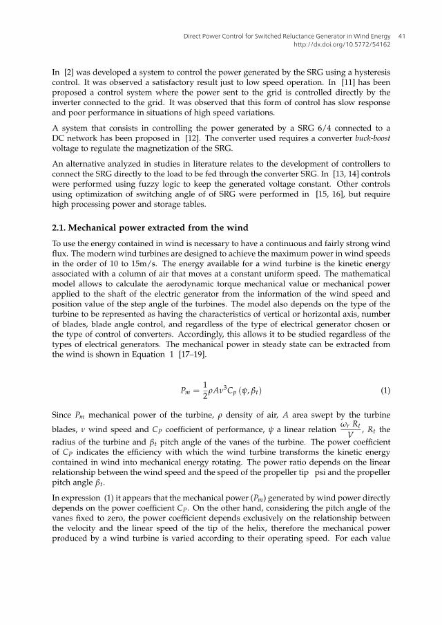
Since Pm mechanical power of the turbine, ρ density of air, A area swept by the turbine
blades, ν wind speed and CP coefficient of performance, ψ a linear relationωr Rt
V, Rt the
radius of the turbine and βt pitch angle of the vanes of the turbine. The power coefficientof CP indicates the efficiency with which the wind turbine transforms the kinetic energycontained in wind into mechanical energy rotating. The power ratio depends on the linearrelationship between the wind speed and the speed of the propeller tip psi and the propellerpitch angle βt.
In expression (1) it appears that the mechanical power (Pm) generated by wind power directlydepends on the power coefficient CP. On the other hand, considering the pitch angle of thevanes fixed to zero, the power coefficient depends exclusively on the relationship betweenthe velocity and the linear speed of the tip of the helix, therefore the mechanical powerproduced by a wind turbine is varied according to their operating speed. For each value
Direct Power Control for Switched Reluctance Generator in Wind Energyhttp://dx.doi.org/10.5772/54162
41

4 Wind Farm
of the wind speed is a region in which the rotor speed maximizes the mechanical powergenerated. Therefore, for wind speeds below rated speed operation with variable speed rotorincreases efficiency in power generation [18, 19]. The profile of optimizing the efficiency ofthe power generated for variable speeds can be expressed by:
Popt = koptw3r (2)
Where Popt is the optimum power and kopt depends of aerodynamics of the helix, gear boxand parameters of the wind turbine.
3. Structure and operation principle of the switched reluctance machine
The switched reluctance machine (SRM) is a primitive conception, and its basic concept ofoperation has been established for around 1838. However, only with the development of thepower electronics has become possible to use this machine operating system for applicationsrequiring variable speed [20].
3.1. Basic structure
SRM is a double salient (in rotor and in stator) having field coils in stator as the DC motor anddoes not have coils or magnets in the rotor. The rotor is composed of ferromagnetic materialwith salient regularly. Figure 2 there is a MRV 8/6 (number of stator poles/rotor polesnumber). Other possibilities existing construction are 6/4, 10/4, 12/8 and 12/10, amongother configurations.
The operation principle of the MRV as motor is based on the principle of minimumreluctance, ie, when the winding on a stator pole pair is energized, the poles of the rotor areattracted to a position that represents the minimum reluctance (axes aligned ), generatinga torque on the rotor. while two rotor poles are aligned with the stator poles other polesare out of alignment rotor. These other stator poles are driven bringing the rotor polesinto alignment. By the sequential switching of the stator windings, there is production ofelectromagnetic torque and the rotor rotates [10].
A
A’
B
B’
D’
C’C
D
stator
rotor
winding
Figure 2. Front view of a switched reluctance machine 8/6.
Modeling and Control Aspects of Wind Power Systems42
Direct Power Control for Switched Reluctance Generator in Wind Energy 5
10.5772/54162
4. The switched reluctance generator (SRG)
The switched reluctance generator (SRG) is an electromechanical energy converter capable oftransforming mechanical energy into electrical energy. To operate as a generator, the machinemust be excited during the degrowth of inductance and a mechanical torque must be appliedon the machine shaft. The magnetization of the phase conjugate added to the input of themechanical axis of the machine causes an emf appears which increases the rate of growth ofthe current curve [9, 21].
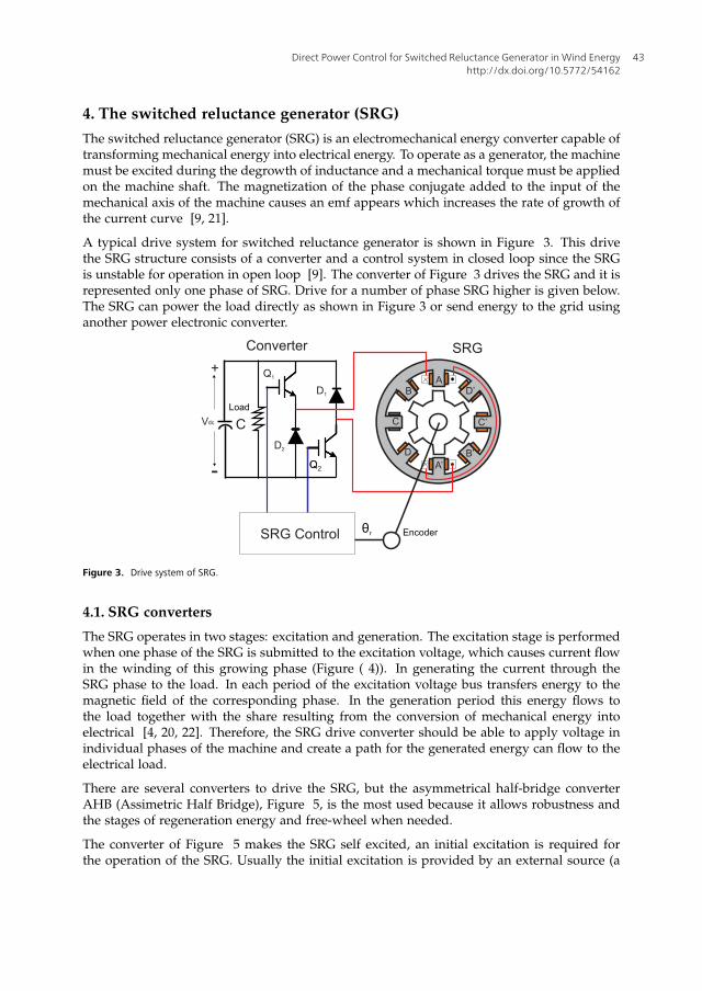
A typical drive system for switched reluctance generator is shown in Figure 3. This drivethe SRG structure consists of a converter and a control system in closed loop since the SRGis unstable for operation in open loop [9]. The converter of Figure 3 drives the SRG and it isrepresented only one phase of SRG. Drive for a number of phase SRG higher is given below.The SRG can power the load directly as shown in Figure 3 or send energy to the grid usinganother power electronic converter.
Figure 3. Drive system of SRG.
4.1. SRG converters
The SRG operates in two stages: excitation and generation. The excitation stage is performedwhen one phase of the SRG is submitted to the excitation voltage, which causes current flowin the winding of this growing phase (Figure ( 4)). In generating the current through theSRG phase to the load. In each period of the excitation voltage bus transfers energy to themagnetic field of the corresponding phase. In the generation period this energy flows tothe load together with the share resulting from the conversion of mechanical energy intoelectrical [4, 20, 22]. Therefore, the SRG drive converter should be able to apply voltage inindividual phases of the machine and create a path for the generated energy can flow to theelectrical load.
There are several converters to drive the SRG, but the asymmetrical half-bridge converterAHB (Assimetric Half Bridge), Figure 5, is the most used because it allows robustness andthe stages of regeneration energy and free-wheel when needed.
The converter of Figure 5 makes the SRG self excited, an initial excitation is required forthe operation of the SRG. Usually the initial excitation is provided by an external source (a
Direct Power Control for Switched Reluctance Generator in Wind Energyhttp://dx.doi.org/10.5772/54162
43

6 Wind Farm
Figure 4. Profile of the Inductance..
Figure 5. Converter AHB four phase.
battery for example) until the capacitor is charged. This pass the same capacitor exciting thephases when the external source is removed. The capacitor also has the function of stabilizingthe voltage delivered to the load.
The Figures 6(a) e 6(b) illustrates the stages of operation of the AHB converter. In theexcitation stage (Figure 6(a)) the two switches (of phase to be excited) turn on. Then acurrent flows from the capacitor to the stage, magnetizing it. After the excitation intervalboth switches are opened and the diodes are now to conduct the generated energy to theload and recharge the capacitor (Figure 6(b)). This process is repeated cyclically for eachphase of the converter.
One of the main advantages of this converter is its flexibility in the control individuallyof current in each phase. Furthermore the converter not allowing short circuit in DC busconverter due to the fact that the switches connected in series with machine winding [10,23]. However, this configuration is not the cheapest, because it requires two semiconductorswitches per phase of the SRG. There are topologies that use less than two switches per phaseof the GRV, as shown in [10, 20, 24], but these topologies have limitations regarding the AHBconverter as the literature describes.
Modeling and Control Aspects of Wind Power Systems44
Direct Power Control for Switched Reluctance Generator in Wind Energy 7
10.5772/54162
(a) (b)
Figure 6. a) Excitation stage b) Generation stage.
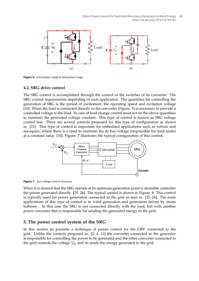
4.2. SRG drive control
The SRG control is accomplished through the control of the switches of its converter. TheSRG control requirements depending of each application. The quantities for controlling thegeneration of SRG is the period of excitement, the operating speed and excitation voltage[10]. When the load is connected directly to the converter (Figure 5) is necessary to provide acontrolled voltage to the load. In case of load change control must act on the above quantitiesto maintain the generated voltage constant. This type of control is known as SRG voltagecontrol bus. There are several controls proposed for this type of configuration as shownin [21]. This type of control is important for embedded applications such as vehicle andaerospace, where there is a need to maintain the dc bus voltage (responsible for food loads)at a constant value [10]. Figure 7 illustrates the typical configuration of this control.
Figure 7. Bus voltage control structure.
When it is desired that the SRG operate at its optimum generation point is desirable controllerthe power generated directly [25, 26]. The typical control is shown in Figure 8. This controlis typically used for power generation connected to the grid as seen in [25, 26]. The mainapplications of this type of control is in wind generation and generators driven by steamturbines . In this case the SRG is not connected directly with the load, but with anotherpower converter that is responsible for sending the generated energy to the grid.
5. The power control system of the SRG
In this section its presents a technique of power control for the GRV connected to thegrid. Unlike the controls proposed in [2, 4, 11] the converter connected to the generatoris responsible for controlling the power to be generated and the other converter connected tothe grid controls the voltage Vdc and its sends the energy generated to the grid.
Direct Power Control for Switched Reluctance Generator in Wind Energyhttp://dx.doi.org/10.5772/54162
45

8 Wind Farm
Figure 8. Generated power control structure.
5.1. Power converters
The converter used to drive the GRV was the AHB converter. This converter is connected viathe DC link with the voltage source converter that it is connected to the grid.
Figure 9. Power converters.
5.2. Direct Power Control
The direct power control system for SRG must regulate the power generated at the point ofmaximum aerodynamic efficiency, in other words, Pre f = koptw
3r , where Pre f is the reference
of active power. The proposed direct power control system consists in control the powergenerated by SRG directly. The diagram of the direct power control is shown in Figure 10.The control consists in keeping angle of activation of the switches of the HB converter ata fixed value θon.The PI controller processes the error (eP) between Pre f and the generatedpower P and controls angle of shutdown of the switches θo f f , as shown in Equation (4).Thus, the principle of the control is when the step of the excitation increases, the generatedpower increases, as well.
The expression for the error power is given by:
eP = Pre f − P (3)
The angle θo f f is given by:
θo f f = KpeP + Ki
∫ePdt (4)
Modeling and Control Aspects of Wind Power Systems46

Direct Power Control for Switched Reluctance Generator in Wind Energy 9
10.5772/54162
where: Kp is the proportional gain and ki is the integral gain of PI controller.
DriveControl
AHB
PIP
Pref +
-
Ɵoff
GRVAHB
ConverterSRG
ID
IC
IB
IA
AbsoluteEncoder
WindTurbine
Current limiter
WindSpeed
Calculationof average
x VdcIdc
Imax
Ɵon
Figure 10. Diagram of direct power control for SRG.
5.2.1. Tuning of PI controller gains
The PI controller gains were adjusted using the second tuning method of Ziegler-Nicholdsdescribed in [27]. Figure 11 illustrates the procedure performed. Initially, the integral gainis zero and sets the proportional gain value (Kp) for the closed loop system, until the pointwhere the response of the system starts to oscillate periodically. This setpoint is known asthe critical point, in which the period of oscillation is defined as the critical period (Pcr)proportional gain and proportional gain is defined as critical (Kcr). From the Pcr e Kcr PIcontroller gains are determined using the relationship shown in Equation 5. This techniqueallows a good initial value of line when you do not know the process of plant be controlled.
Kp = 0.45Kcr
Ki =1
2PcrKcr (5)
Figure 11. Second tuning method of Ziegler-Nicholds.
Direct Power Control for Switched Reluctance Generator in Wind Energyhttp://dx.doi.org/10.5772/54162
47

10 Wind Farm
5.3. Power Grid Connection Converter
The Voltage Source Converter (VSC), shown in Figure 9, controls the voltage Vdc and it allowsto send the generated power by SRG to the grid. The control strategy applied to the convertervoltage source consists of two control loops. There is an internal control loop that controlsthe current sent to the grid, and, externally, there is a control loop of bus voltage control(Vdc). The current loop control (isd, isq) is responsible for controlling the power factor of thepower sent to the grid [28]. The control voltage of the DC link is responsible for balancingthe flow of power between the SRG and the grid [29].
The DC link voltage control of the voltage source inverter is realized in the synchronouscoordinate system (dq) with employment grid voltage angle (θ = wt) used in thetransformation abc dq, which is obtained using a Phase-Locked Loop (PLL). The controlvoltage of the DC link (Vdc) is performed by a PI controller, which comes from the referencevalue i∗sd (6), while the value of i∗sq is derived from the power factor desired FP and Pre f (7).
i∗sd = Kpi(V∗dc − Vdc) + Kii
∫
(V∗dc − Vdc)dt (6)
i∗sq =−3
2P̂re f
√1 − FP2
FP2(7)
The reference values of current are compared with the values obtained from electrical grid(isd e isq) and are processed by two PI controllers that generate the value of the space vectorvoltage of grid ~v
dq(8) and (9) in the synchronous coordinate system (Equation 10). This
space vector is transformed for the coordinate system abc generating the signals voltagevmodabc
(Equation 11) which are then generated using the PWM sinusoidal. The control systemfor VSC is shown in Figure 12.
vds = Kps(i∗sd − isd) + Kis
∫
(i∗sd − isd)dt (8)
vqs = Kps(i∗sq − isq) + Kis
∫
(i∗sq − isq)dt (9)
[
idiq
]
=2
3
[
cosθ senθ
−senθ cosθ
]
[
1 − 12 − 1
2
0√
32 −
√3
2
]
ia
ibic
(10)
vmoda
vmodb
vmodc
=
1 0
− 12
√3
2
− 12
−√
32
[
cosθ −senθ
senθ cosθ
]
[
vmodd
vmodq
]
(11)
Modeling and Control Aspects of Wind Power Systems48

Direct Power Control for Switched Reluctance Generator in Wind Energy 11
10.5772/54162
VSC
dq
abc
dq
abc
PI
PLL
PWM
Vdc
Vdc
Vdc* +-
+ -
isq *
isq
+ -
isd *
isd ,isq
vsd ,vsq
Os
Grid
Rs
Ls
C
isd
V’abc
Iabc
PI
PI
vds
vqs
vabc
Calculation
isq*
Pref
FPref
Figure 12. Block diagram of vector control of the converter connected to the grid.
5.4. PWM sinusoidal (SPWM)
There are several modulation techniques performed on the VSC to obtain a modulatedvoltage Vmod
abcin the terminals of the converter [30]. The most used technique is known
as PWM sinusoidal (SPWM) using a triangular carrier for generating waveform desired [31].
SPWM modulation is obtained by comparing a reference voltage (sinusoidal) with a signalsymmetrical triangular. The frequency of the triangular wave is to be at least 20 times greaterthan the maximum frequency of the reference signal, so that it is possible to obtain anacceptable reproduction of the waveform after filtering [32].
Figure 13. Modulation PWM sinusoidal
Direct Power Control for Switched Reluctance Generator in Wind Energyhttp://dx.doi.org/10.5772/54162
49
12 Wind Farm
The Figures 13 shows the three-phase SPWM modulation signals used in this work. Thecarrier is compared with the reference sine wave for each phase, so that: when the carrier isgreater than the reference phase, the switch top to respective phase is activated, otherwisethe switch is operated below. Thus the output voltage of the modulated VSC is formed by asuccession of rectangular wave. With a low pass filter can eliminate harmonic componentsgenerated by the modulation.
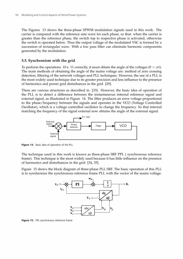
5.5. Synchronism with the grid
To perform the operations 10 e 11 correctly, it must obtain the angle of the voltages (θ = wt).The main methods of obtaining the angle of the mains voltage are: method of zero crossingdetection, filtering of the network voltages and PLL techniques. However, the use of a PLL isthe most widely used technique due to its greater precision and less influence to the presenceof harmonics and power grid disturbances in the grid [29].
There are various structures as described in [33]. However, the basic idea of operation ofthe PLL is to detect a difference between the instantaneous internal reference signal andexternal signal, as illustrated in Figure 14. The filter produces an error voltage proportionalto the phase/frequency between the signals and operates in the VCO (Voltage ControlledOscillator), which is a voltage controlled oscillator to change the frequency. So that internalmatching the frequency of the signal external now obtains the angle of the external signal.
Figure 14. Basic idea of operation of the PLL.
The technique used in this work is known as three-phase SRF PPL ( synchronous referenceframe). This technique is the most widely used because it has little influence on the presenceof harmonics and disturbances in the grid [34, 35].
Figure 15 shows the block diagram of three-phase PLL SRF. The basic operation of this PLLis to synchronize the synchronous reference frame PLL with the vector of the mains voltage.
Figure 15. PPL synchronous reference frame
Modeling and Control Aspects of Wind Power Systems50
Direct Power Control for Switched Reluctance Generator in Wind Energy 13
10.5772/54162
The voltages of the network (va, vb, Vc) are obtained and then are transformed to stationaryreference frame, using Equation 12. So has vα e vβ using the proper angle estimated (θ2),the variables vα and vβ are transformed into the synchronous reference frame (Equation 13)resulting in tensionsvd e vq. Reference voltage v∗d is set to zero. The error between vd and v∗dis processed by a PI controller that changes the value of (θ2) in order to reset this error. When(θ2) tends to the value of (θ1) the sine tends to zero and the PLL is locked. In this situation,the value Vq is equal to the amplitude of the input voltages. The frequency obtained directly(w f f ) is added to improve the performance of the PLL.
[
vα
vβ
]
=
[
1 − 12 − 1
2
0√
32 −
√3
2
]
va(t) = Vcos(θ1)
vb(t) = Vcos(θ1 −4π3 )
vc(t) = Vcos(θ1 −2π3 )
=
[
Vcosθ1
−Vsenθ1
]
(12)
[
vd
vq
]
=
[
cosθ senθ−senθ cosθ
] [
vα
vβ
]
=
[
−Vsen(θ1 − θ2)Vcos(θ1 − θ2)
]
(13)
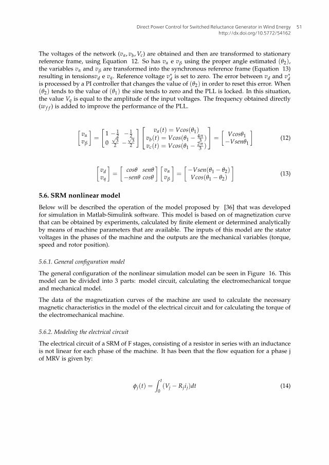
5.6. SRM nonlinear model
Below will be described the operation of the model proposed by [36] that was developedfor simulation in Matlab-Simulink software. This model is based on of magnetization curvethat can be obtained by experiments, calculated by finite element or determined analyticallyby means of machine parameters that are available. The inputs of this model are the statorvoltages in the phases of the machine and the outputs are the mechanical variables (torque,speed and rotor position).
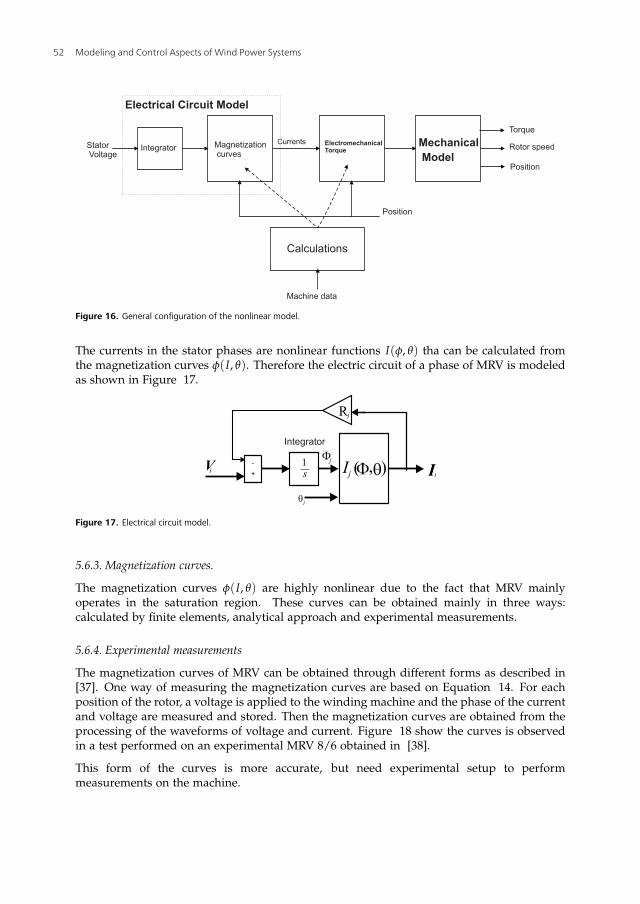
5.6.1. General configuration model
The general configuration of the nonlinear simulation model can be seen in Figure 16. Thismodel can be divided into 3 parts: model circuit, calculating the electromechanical torqueand mechanical model.
The data of the magnetization curves of the machine are used to calculate the necessarymagnetic characteristics in the model of the electrical circuit and for calculating the torque ofthe electromechanical machine.
5.6.2. Modeling the electrical circuit
The electrical circuit of a SRM of F stages, consisting of a resistor in series with an inductanceis not linear for each phase of the machine. It has been that the flow equation for a phase jof MRV is given by:
φj(t) =∫ t
0(Vj − Rjij)dt (14)
Direct Power Control for Switched Reluctance Generator in Wind Energyhttp://dx.doi.org/10.5772/54162
51
14 Wind Farm
Figure 16. General configuration of the nonlinear model.
The currents in the stator phases are nonlinear functions I(φ, θ) tha can be calculated fromthe magnetization curves φ(I, θ). Therefore the electric circuit of a phase of MRV is modeledas shown in Figure 17.
Figure 17. Electrical circuit model.
5.6.3. Magnetization curves.
The magnetization curves φ(I, θ) are highly nonlinear due to the fact that MRV mainlyoperates in the saturation region. These curves can be obtained mainly in three ways:calculated by finite elements, analytical approach and experimental measurements.
5.6.4. Experimental measurements
The magnetization curves of MRV can be obtained through different forms as described in[37]. One way of measuring the magnetization curves are based on Equation 14. For eachposition of the rotor, a voltage is applied to the winding machine and the phase of the currentand voltage are measured and stored. Then the magnetization curves are obtained from theprocessing of the waveforms of voltage and current. Figure 18 show the curves is observedin a test performed on an experimental MRV 8/6 obtained in [38].
This form of the curves is more accurate, but need experimental setup to performmeasurements on the machine.
Modeling and Control Aspects of Wind Power Systems52

Direct Power Control for Switched Reluctance Generator in Wind Energy 15
10.5772/54162
Figure 18. Experimental curver measurements.
5.6.5. Electromechanical torque
The electromechanical torque in SRM is the sum of the individual torques developed ateach stage. When the magnetization curves are obtained experimentally or finite elementelectromechanical torque may be calculated using the equation of torque:
Te =δW
′
f
δθ=
δW′
f (i, θ)
δθ=
dL(i, θ)
dθ
i2
2(15)
Where (W′
f ) is the coenergy.
5.6.6. Mechanical model
The equation of the mechanical model is given by:
Tm = Temag − Dw − Jdw
dt(16)
The mechanical model is then modeled as shown in Figure 19.
Js +B
1
+
-
q
Te
+
+
+
T1
T2
Tn
Tc
s
1w
Figure 19. Mechanical model.
5.7. Machine model in Simulink
The nonlinear model developed by [36] became a block from the Simulink librarySimPowerSystem. This block has an operating structure that can be viewed in Figure 20.From the data of magnetization of the two tables are created MRV. The table of current (ITBL)used in the model circuit and the torque table (TTBL) that gets the touch electromechanical
Direct Power Control for Switched Reluctance Generator in Wind Energyhttp://dx.doi.org/10.5772/54162
53
16 Wind Farm
each phase. For input values that do not exist in the tables the outputs are obtained by linearinterpolation. The total electromechanical torque is obtained by summing the phases torquesand sent to the mechanical model. The rotor position is obtained by integrating the speed ofthe machine. The bold lines refer to multiple streams of data that depends on the number ofphases of the machine. The currents obtained from the table of the currents are generated atthe terminals of the machine model.
Figure 20. Diagram SRM model in Simulink.
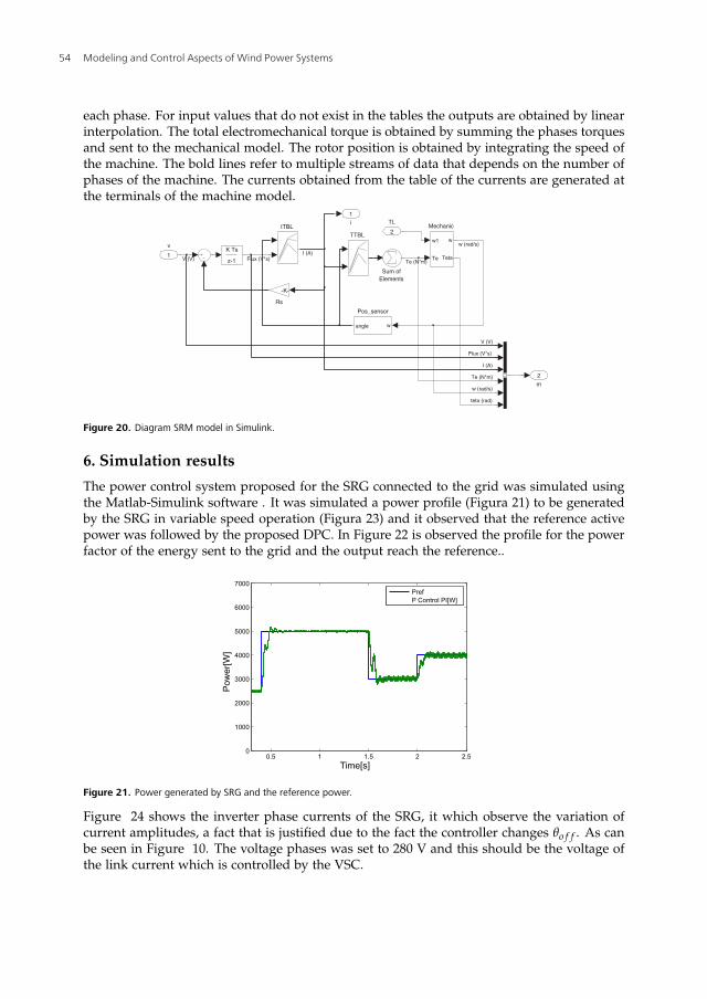
6. Simulation results
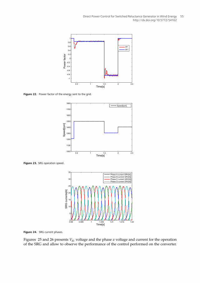
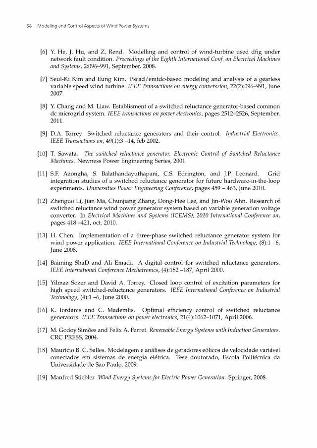
The power control system proposed for the SRG connected to the grid was simulated usingthe Matlab-Simulink software . It was simulated a power profile (Figura 21) to be generatedby the SRG in variable speed operation (Figura 23) and it observed that the reference activepower was followed by the proposed DPC. In Figure 22 is observed the profile for the powerfactor of the energy sent to the grid and the output reach the reference..
Figure 21. Power generated by SRG and the reference power.
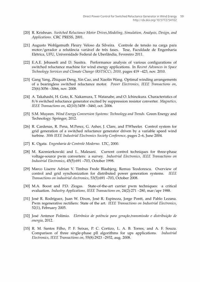
Figure 24 shows the inverter phase currents of the SRG, it which observe the variation ofcurrent amplitudes, a fact that is justified due to the fact the controller changes θo f f . As canbe seen in Figure 10. The voltage phases was set to 280 V and this should be the voltage ofthe link current which is controlled by the VSC.
Modeling and Control Aspects of Wind Power Systems54
Direct Power Control for Switched Reluctance Generator in Wind Energy 17
10.5772/54162
Figure 22. Power factor of the energy sent to the grid.
Figure 23. SRG operation speed.
Figure 24. SRG current phases.
Figures 25 and 26 presents Vdc voltage and the phase a voltage and current for the operationof the SRG and allow to observe the performance of the control performed on the converter.
Direct Power Control for Switched Reluctance Generator in Wind Energyhttp://dx.doi.org/10.5772/54162
55

18 Wind Farm
In Figure 26 is observed the voltage and phase current from the power grid. The THD (TotalHarmonic Distortion) of the current sent to the grid analyzed by FFT ( emph Fast FourierTransform) (Figure 27) was 1.57%.
Figure 25. Voltage Vdc controlled by VSC.
Figure 26. Phase a voltage and current grid.
Figure 27. THD and harmonic components of the phase current.
Modeling and Control Aspects of Wind Power Systems56

Direct Power Control for Switched Reluctance Generator in Wind Energy 19
10.5772/54162
7. Conclusions
This book chapter was presented a proposal for direct control of power for a SRG. The DPCcontroller allows the power control of the generator directly without using current loops.The controller has a satisfactory performance and no complexity for its implementation. TheAHB converter allows robustness and the stages of regeneration energy and freewheel whenneeded. The simulation results confirm the effectiveness of the power controller duringconditions of generator operation at variable speed and with different reference values ofactive power and power factor. Thus, the strategy of direct control of power is an interestingtool to control the power of the variable reluctance generator powered wind turbines.
Acknowledgements
The authors acknowledge FAPESP, CNPq and CAPES by the financial support.
Author details
Tárcio A. dos S. Barros1,⋆,Alfeu J. Sguarezi Filho2 and Ernesto Ruppert Filho1
⋆ Address all correspondence to: [email protected]
1 Universidade Estadual de Campinas-UNICAMP, Faculdade de Engenharia Elétrica eComputação-FEEC, DSCE, Campinas, Brazil2 Universidade Federal do ABC-UFABC, Santo André, Brazil
References
[1] Association World Wind Energy. The World Wind Energy 2011 report, 2012.
[2] McSwiggan D., L. Xu, and T Littler. Modelling and control of a variable-speed switchedreluctance generator based wind turbine. Universities Power Engineering Conference,pages 459 – 463, June 2007.
[3] K. Ogawa, N. Yamamura, and M. Ishda. Study for small size wind power generatingsystem using switched reluctance generator. IEEE International Conference on IndustrialTechnology, pages 1510–1515, 2006.
[4] R. Cardenas, R. Pena, M. Perez, G. Claro, J. Asher, and P. Wheeler. Control of a switchedreluctance generator for variable-speed wind energy applications. IEEE Transactions onenergy conversrion, 20(4):691 –703, December 2005.
[5] Alfeu J. Sguarezi Filho. Controle de potências ativa e reativa de geradores de induçãotrifásicos de rotor bobinado para aplicação em geração eólica com a utilização decontroladores baseados no modelo matemático dinâmico do gerador. Tese doutorado,Faculdade de Engenharia Elétrica e Computação, Unicamp - Universidade Estadual deCampinas, Novembro 2010.
Direct Power Control for Switched Reluctance Generator in Wind Energyhttp://dx.doi.org/10.5772/54162
57
20 Wind Farm
[6] Y. He, J. Hu, and Z. Rend. Modelling and control of wind-turbine used dfig undernetwork fault condition. Proceedings of the Eighth International Conf. on Electrical Machinesand Systems, 2:096–991, September. 2008.
[7] Seul-Ki Kim and Eung Kim. Pscad/emtdc-based modeling and analysis of a gearlessvariable speed wind turbine. IEEE Transactions on energy conversrion, 22(2):096–991, June2007.
[8] Y. Chang and M. Liaw. Establisment of a switched reluctance generator-based commondc microgrid system. IEEE transactions on power electronics, pages 2512–2526, September.2011.
[9] D.A. Torrey. Switched reluctance generators and their control. Industrial Electronics,IEEE Transactions on, 49(1):3 –14, feb 2002.
[10] T. Sawata. The switched reluctance generator, Electronic Control of Switched ReluctanceMachines. Newness Power Engineering Series, 2001.
[11] S.F. Azongha, S. Balathandayuthapani, C.S. Edrington, and J.P. Leonard. Gridintegration studies of a switched reluctance generator for future hardware-in-the-loopexperiments. Universities Power Engineering Conference, pages 459 – 463, June 2010.
[12] Zhenguo Li, Jian Ma, Chunjiang Zhang, Dong-Hee Lee, and Jin-Woo Ahn. Research ofswitched reluctance wind power generator system based on variable generation voltageconverter. In Electrical Machines and Systems (ICEMS), 2010 International Conference on,pages 418 –421, oct. 2010.
[13] H. Chen. Implementation of a three-phase switched reluctance generator system forwind power application. IEEE International Conference on Industrial Technology, (8):1 –6,June 2008.
[14] Baiming ShaD and Ali Emadi. A digital control for switched reluctance generators.IEEE International Conference Mechatronics, (4):182 –187, April 2000.
[15] Yilmaz Sozer and David A. Torrey. Closed loop control of excitation parameters forhigh speed switched-reluctance generators. IEEE International Conference on IndustrialTechnology, (4):1 –6, June 2000.
[16] K. Iordanis and C. Mademlis. Optimal efficiency control of switched reluctancegenerators. IEEE Transactions on power electronics, 21(4):1062–1071, April 2006.
[17] M. Godoy Simões and Felix A. Farret. Renewable Energy Systems with Induction Generators.CRC PRESS, 2004.
[18] Maurício B. C. Salles. Modelagem e análises de geradores eólicos de velocidade variávelconectados em sistemas de energia elétrica. Tese doutorado, Escola Politécnica daUniversidade de São Paulo, 2009.
[19] Manfred Stiebler. Wind Energy Systems for Electric Power Generation. Springer, 2008.
Modeling and Control Aspects of Wind Power Systems58
Direct Power Control for Switched Reluctance Generator in Wind Energy 21
10.5772/54162
[20] R. Krishnan. Switched Reluctance Motor Drives,Modeling, Simulation, Analysis, Design, andApplications. CRC PRESS, 2001.
[21] Augusto Wohlgemuth Fleury Veloso da Silveira. Controle de tensão na carga paramotor/gerador a relutância variável de três fases. Tese, Faculdade de EngenhariaElétrica, UFU, Universidade Federal de Uberlândia, Fevereiro 2011.
[22] E.A.E. Jebaseeli and D. Susitra. Performance analysis of various configurations ofswitched reluctance machine for wind energy applications. In Recent Advances in SpaceTechnology Services and Climate Change (RSTSCC), 2010, pages 419 –423, nov. 2010.
[23] Gang Yang, Zhiquan Deng, Xin Cao, and Xiaolin Wang. Optimal winding arrangementsof a bearingless switched reluctance motor. Power Electronics, IEEE Transactions on,23(6):3056 –3066, nov. 2008.
[24] A. Takahashi, H. Goto, K. Nakamura, T. Watanabe, and O. Ichinokura. Characteristics of8/6 switched reluctance generator excited by suppression resistor converter. Magnetics,IEEE Transactions on, 42(10):3458 –3460, oct. 2006.
[25] S.M. Muyeen. Wind Energy Conversion Systems: Technology and Trends. Green Energy andTechnology. Springer, 2012.
[26] R. Cardenas, R. Pena, M.Perez, G. Asher, J. Clare, and P.Wheeler. Control system forgrid generation of a switched reluctance generator driven by a variable speed windturbine. 30th IEEE Industrial Electronics Society Conference, pages 2–6, June 2004.
[27] K. Ogata. Engenharia de Controle Moderno. LTC, 2000.
[28] M. Kazmierkowski and L. Malesani. Current control techniques for three-phasevoltage-source pwm converters: a survey. Industrial Electronics, IEEE Transactions onIndustrial Electronics, 45(5):691 –703, October 1998.
[29] Marco Liserre Adrian V. Timbus Frede Blaabjerg, Remus Teodorescu. Overview ofcontrol and grid synchonization for distributed power generation systems. IEEETransactions on industrial electronics, 53(5):691 –703, October 2008.
[30] M.A. Boost and P.D. Ziogas. State-of-the-art carrier pwm techniques: a criticalevaluation. Industry Applications, IEEE Transactions on, 24(2):271 –280, mar/apr 1988.
[31] José R. Rodríguez, Juan W. Dixon, José R. Espinoza, Jorge Pontt, and Pablo Lezana.Pwm regenerative rectifiers: State of the art. IEEE Transactions on Industrial Electronics,52(1), February 2005.
[32] José Antenor Polímio. Eletrônica de potência para geração,transmissão e distribuição deenergia, 2012.
[33] R. M. Santos Filho, P. F. Seixas, P. C. Cortizo, L. A. B. Torres, and A. F. Souza.Comparison of three single-phase pll algorithms for ups applications. IndustrialElectronics, IEEE Transactions on, 55(8):2923 –2932, aug. 2008.
Direct Power Control for Switched Reluctance Generator in Wind Energyhttp://dx.doi.org/10.5772/54162
59
22 Wind Farm
[34] F. Liccardo, P. Marino, and G. Raimondo. Robust and fast three-phase pll trackingsystem. Industrial Electronics, IEEE Transactions on, 58(1):221 –231, jan. 2011.
[35] D. Jovcic. Phase locked loop system for facts. Power Systems, IEEE Transactions on,18(3):1116 – 1124, aug. 2003.
[36] H. Le-Huy and P. Brunelle. A versatile nonlinear switched reluctance motor modelin simulink using realistic and analytical magnetization characteristics. In IndustrialElectronics Society, 2005. IECON 2005. 31st Annual Conference of IEEE, page 6 pp., nov.2005.
[37] Wen Ding and Deliang Liang. A fast analytical model for an integrated switchedreluctance starter/generator. Energy Conversion, IEEE Transactions on, 25(4):948 –956,dec. 2010.
[38] T.J.E. Miller and M. McGilp. Nonlinear theory of the switched reluctance motor forrapid computer-aided design. Electric Power Applications, IEE Proceedings B, 137(6):337–347, nov 1990.
Modeling and Control Aspects of Wind Power Systems60