![Duravit Spare Parts List - HM Wallace · [2] – Flush valve for 2pc toilet, Geberit HET 0074138600 85 [3] – Flush valve gasket for Geberit HET, “flapper” 1002970000 10 Extension](https://static.fdocuments.us/doc/165x107/5f37231201ea7949f2139e83/duravit-spare-parts-list-hm-wallace-2-a-flush-valve-for-2pc-toilet-geberit.jpg)
direct flush urinal control valve - Cistermiser Ltd · direct flush urinal control valve...
16
direct flush urinal control valve 0118 969 1611 | [email protected] | www.cistermiser.co.uk installation guide The direct flush valve provides automatic flushing of the urinal after use ensuring the highest level of hygiene from the minimum volume of water. No cistern is required. Once installed the operation is entirely automatic with continuous monitoring of user behaviour and washroom demand. One direct flush is required for each urinal. The direct flush detects users at the bowl and flushes when the user departs. If a user is detected while the valve is flushing the direct flush will pause the flush to prevent splashing of the user and save water: this is called the “flush arrest” function. After 12 hours without use the direct flush automatically runs a hygiene flush: this feature can be turned off. 1 Introduction The cost effective solution to maximise urinal hygiene and water economy. direct flush discreet (DFD) direct flush accessible (DFA) 31198 Direct Flush Installation Guide 25_6:18362 Sensazone Insert 2/7/13 10:27 Page 2
-
Upload
vuongkhanh -
Category
Documents
-
view
232 -
download
0
Transcript of direct flush urinal control valve - Cistermiser Ltd · direct flush urinal control valve...

direct flush urinalcontrol valve
0118 969 1611 | [email protected] | www.cistermiser.co.uk
installation guide
The direct flush valve provides automatic flushing of theurinal after use ensuring the highest level of hygiene fromthe minimum volume of water. No cistern is required. Onceinstalled the operation is entirely automatic with continuousmonitoring of user behaviour and washroom demand. Onedirect flush is required for each urinal.
The direct flush detects users at the bowl and flusheswhen the user departs. If a user is detected while the valveis flushing the direct flush will pause the flush to preventsplashing of the user and save water: this is called the“flush arrest” function.
After 12 hours without use the direct flush automaticallyruns a hygiene flush: this feature can be turned off.
1 IntroductionThe cost effective solution to maximise urinal hygiene and water economy.
direct flush discreet (DFD)direct flush accessible (DFA)
31198 Direct Flush Installation Guide 25_6:18362 Sensazone Insert 2/7/13 10:27 Page 2

direct flush accessiblesupplied parts1 Mount box2 Valve unit3 DC pipe interrupter
inc 4lpm flow regulator (grey)4 Clamp frame5 Sensor plate6 Mains adaptor7 Battery case8 Screws9 Shoulder washer10 2mm allen key11 15mm pipe fitting12 1.5m cable13 Filter14 Washer15 3lpm flow regulator (brown)16 5lpm flow regulator (yellow)17 Seal18 DC Pipe Interrupter jet19 Adhesive pads
0118 969 1611 | [email protected] | www.cistermiser.co.uk
direct flush discreetsupplied parts
1
x 21 Sensor unit2 Valve unit3 DC pipe interrupter
inc 4lpm flow regulator (grey)4 Sensor nut5 Rubber gasket6 Clamp plate7 Mains adaptor8 Battery case9 Screws10 Screw packer11 15mm pipe fitting12 1.5m cable13 Filter14 Washer15 3lpm flow regulator (brown)16 5lpm flow regulator (yellow)17 Seal18 DC Pipe Interrupter jet19 Adhesive pads
1 5 9 10
84
5
6
10
11
7
A
B
C
x 8
x 4
x 1
8
13
12
14
15
17
18
19
3
4
3
762
2
x 4
x 19 A
B
16
x 2
11
12
x 4
13
14
15
17
18
19
16
x 4
31198 Direct Flush Installation Guide 25_6:18362 Sensazone Insert 2/7/13 10:27 Page 3

0118 969 1611 | [email protected] | www.cistermiser.co.uk
2 Installation
Important notes and guidelines: read this before fitting the urinal valve whenflushing directly from the mains supply
why is a DC pipe interruptersupplied?When urinals are flushed directly from the mainswater supply, the Water Regulations require thatthe water supply be protected by a suitablecategory 5 protection method or device.
In the case of urinals, this can be achieved in threeways:
1. The use of a WRAS approved type DC pipeinterrupter (supplied with Cistermiser DirectFlush).
2. The use of a dedicated supply for flushinguse only, supplied from a break tank thatprotects the mains supply with a type AA,AB or AD air gap.
3. The use of a specific type of urinal which hasbeen tested and shown to incorporate theequivalent of a type AB air gap.
what are the possible implications offitting a DC pipe interrupter?1. Water may overflow from the DC pipe
interrupter if the sparge or pipe run leading tothe sparge is too restrictive. (See diagramoverleaf). This may also occur if there are toomany bends in the pipework.
2. If the feed to the urinal is coming directly fromthe mains water supply, the pressure may betoo high for the sparge and bowl andsplashing may occur in the urinal bowl.
3. System pressure is lost when a DC pipeinterrupter if fitted, therefore the flushperformance may change after installing aDC pipe interrupter.
how to install a DC pipeinterrupter correctly1. To avoid overflowing:• Install a free-flowing, low restriction sparge.• Install the DC pipe interrupter and valve as high
as possible and use as long a pipe run betweenthe pipe interrupter and the sparge as possible.(See diagram overleaf)
• Select the appropriate flow regulator to matchthe flow through the urinal sparge provided.
• Use a large pipe size in the pipework betweenthe DC pipe interrupter and the sparge.
• Minimise pipe bends between the DC pipeinterrupter and the sparge.
2. To avoid splashing:
• Fit a sparge and urinal bowl to accommodatethe pressure.
• Select the appropriate flow regulator to fit ontothe pipe interrupter provided.
NOTE: When using flexible pipes: flexiblepipes typically have a smaller internaldiameter than copper pipes. A greaterdistance between the valve and sparge maytherefore be required. Ensure there are nokinks in the flexible pipe.
A
A
NOTE: For grey water/rain water harvesting.Ensure adequate filtering is fitted, a 10µmfilter is recommended. For chemical watertreatment. If the water system has beentreated with chemicals, ensure the system isthoroughly flushed before fitting anyCistermiser products. Concentrated chemicalsin dead legs can damage the product andresult in failure. If the water is treated withChlorine Dioxide (ClO2), concentration levelsmust be maintained below 5ppm.
NOTE: As with all water containing products,limescale in hard water areas can affect theproducts performance. This can result inmaintenance to remove the limescale as andwhen required.
31198 Direct Flush Installation Guide 25_6:18362 Sensazone Insert 2/7/13 10:27 Page 4
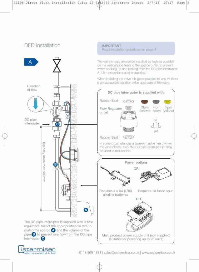
Requires 4 x AA (LR6)alkaline batteries
Requires 1A fused spur
Multi product power supply unit (not supplied)(suitable for powering up to 20 units)
Power options
OR
OR
0118 969 1611 | [email protected] | www.cistermiser.co.uk
DC pipeinterrupter
Directionof flow
DFD installation
The valve should always be installed as high as possibleon the vertical pipe feeding the sparge outlet to preventwater backing up and leaking from the DC pipe interrupter.A 1.5m extension cable is supplied.
When installing the valve it is good practice to ensure thereis an accessible isolation valve upstream of the valve.
Typically
more
than500m
m
DC pipe interrupter is supplied with:
IMPORTANTRead installation guidelines on page 4
The DC pipe interrupter is supplied with 3 flowregulators. Select the appropriate flow rate tomatch the sparge and the volume of thepipe to prevent overflow from the DC pipeinterrupter
AB
C
A
B
C
A
Rubber Seal
Flow Regulatoror Jet
Rubber Seal
In some circumstances a squeak maybe heard whenthe valve closes. If so, the DC pipe interrupter jet maybe used to reduce this.
3lpm(brown)
4lpm(grey)
5lpm(yellow)
or
jet
31198 Direct Flush Installation Guide 25_6:18362 Sensazone Insert 2/7/13 10:27 Page 5
0118 969 1611 | [email protected] | www.cistermiser.co.uk
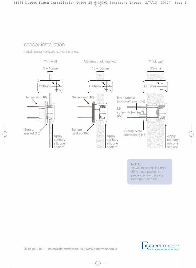
Sensorgasket (15)
Sensorgasket (15)
Ø38mm Ø44mm Ø38mm
Applysanitarysiliconesealant
Applysanitarysiliconesealant
Applysanitarysiliconesealant
Sensor nut (16) Sensor nut (16)
Clamp plate(reversible) (18)
6mm packer(optional* see note)
M4screw(22)
Thin wall Medium thickness wall Thick wall
3 – 15mm 15 – 30mm 35mm+
sensor installationInstall sensor vertically above the urinal.
NOTE:*If wall thickness is under35mm use packer toprevent screw causingdamage to sensor
31198 Direct Flush Installation Guide 25_6:18362 Sensazone Insert 2/7/13 10:27 Page 6

DC pipe interrupter is supplied with:
Rubber Seal
Flow Regulatoror Jet
Rubber Seal
In some circumstances a squeak may be heardwhen the valve closes. If so, the DC pipeinterruptor jet may be used to mitigate this.
0118 969 1611 | [email protected] | www.cistermiser.co.uk
DFA – option 1 wall mounted
NOTE:The bottom of the mount box shouldalways be installed as high as possible onthe vertical pipe feeding the sparge outlet toprevent water backing up and leaking fromthe DC pipe interrupter.
NOTE:4 long screws are provided to allow forflexible fixing of the mount box and clampframe, if required.
SEENOTE
BELOW
The DC pipe interrupter is supplied with 3 flowregulators. Select the appropriate flow rate tomatch your rate through the sparge andsufficient volume of the pipe to preventoverflow from the DC pipe interrupter
AB
C
A
B
C
3lpm(brown)
4lpm(grey)
5lpm(yellow)
or
jet
A
B
31198 Direct Flush Installation Guide 25_6:18362 Sensazone Insert 2/7/13 10:27 Page 7

0118 969 1611 | [email protected] | www.cistermiser.co.uk
or
Power connector
DFA – option 2 panel mounted
NOTE:The bottom of the mount box shouldalways be installed as high as possible onthe vertical pipe feeding the sparge outlet toprevent water backing up and leaking fromthe DC pipe interrupter.
SEENOTE
OPPOSITE
NOTE:Please referto DFA -option 1 fordetails onDC pipeinterrupter.
A
B
C
A
A
C
DFD & DFA - fitting sensor plate
NOTE:See section3 - powerconnections
31198 Direct Flush Installation Guide 25_6:18362 Sensazone Insert 2/7/13 10:27 Page 8

0118 969 1611 | [email protected] | www.cistermiser.co.uk
Batteries: Open the battery case and fit 4 AlkalineAA (LR-6) batteries as indicated. Reseal and fasteninto place on the panel using screws or with thetape pads (for DFA installations slide into themount box).
If using the mains adaptor, fasten into place on thepanel in a dry location using screws or with thesticky pads (for DFA installations slide into themount box) and connect the un-terminated mainscable to a 50Hz 230V AC single phase supply viaa 1A fused spur (not supplied).
Connect the spade connectors from the sensor(DFD) or sensor plate (DFA) to the solenoid terminals– take care to connect the wires according to thecolour coding on the label. If these are not longenough they can be extended by up to 1.5 metres.(Extension cable supplied with DFD).
electrical connection:Connect the power connector from the sensor(DFD) or sensor plate (DFA) to the mains adaptor,or in the case of a battery powered installation, thebattery case.
3 Power connections
NOTE:Remove the label from the sensor BEFOREconnecting to the power. When the power isfirst connected the LED in the sensor flashesamber. This is normal and lasts only a fewseconds.
NOTE:Only one power source should be connectedat any time, either mains or batteries. It is notpossible to connect both simultaneously.
Battery caserequires 4 x AA alkaline batteries
Power options
Mains adaptorrequires 1A fused spur
Multi product power supply unit (not supplied,contact Cistermiser for further details).Suitable for powering up to 20 units
Power connector
Additional configuration options with the Infrared configuration unit (ICU) remote control (sold separately)• Hygiene flush on/off. The installer is able to switch the 12 hr hygiene rinse function on or off.• Clean mode. The direct flush can be disabled for a short period to allow for cleaning.• Siphonic trap refill mode. When activated this allows a small flush after every flush to refill the siphonic trap.
A
A
31198 Direct Flush Installation Guide 25_6:18362 Sensazone Insert 2/7/13 10:27 Page 9
0118 969 1611 | [email protected] | www.cistermiser.co.uk
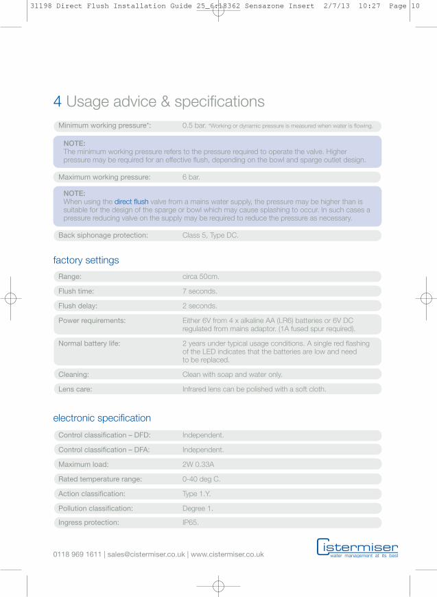
4 Usage advice & specifications
factory settings
electronic specification
Control classification – DFD: Independent.
Control classification – DFA: Independent.
Maximum load: 2W 0.33A
Rated temperature range: 0-40 deg C.
Action classification: Type 1.Y.
Pollution classification: Degree 1.
Ingress protection: IP65.
Range: circa 50cm.
Flush time: 7 seconds.
Flush delay: 2 seconds.
Power requirements: Either 6V from 4 x alkaline AA (LR6) batteries or 6V DCregulated from mains adaptor. (1A fused spur required).
Normal battery life: 2 years under typical usage conditions. A single red flashingof the LED indicates that the batteries are low and needto be replaced.
Cleaning: Clean with soap and water only.
Lens care: Infrared lens can be polished with a soft cloth.
Back siphonage protection: Class 5, Type DC.
Minimum working pressure*: 0.5 bar. *Working or dynamic pressure is measured when water is flowing.
Maximum working pressure: 6 bar.
NOTE:The minimum working pressure refers to the pressure required to operate the valve. Higherpressure may be required for an effective flush, depending on the bowl and sparge outlet design.
NOTE:When using the direct flush valve from a mains water supply, the pressure may be higher than issuitable for the design of the sparge or bowl which may cause splashing to occur. In such cases apressure reducing valve on the supply may be required to reduce the pressure as necessary.
31198 Direct Flush Installation Guide 25_6:18362 Sensazone Insert 2/7/13 10:27 Page 10

0118 969 1611 | [email protected] | www.cistermiser.co.uk
5 Component dimensions
DFD
DFA
41mm
48mm 27mm
82mm
111mm 83mm
180mm
37mm
133mm
154mm
180mm
193mm
31198 Direct Flush Installation Guide 25_6:18362 Sensazone Insert 2/7/13 10:27 Page 11
x 2
0118 969 1611 | [email protected] | www.cistermiser.co.uk
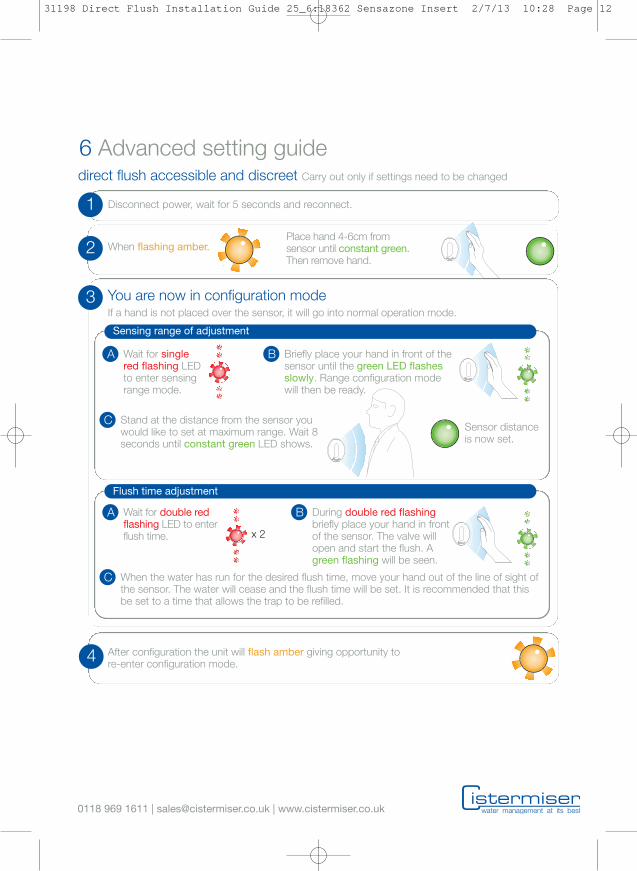
6 Advanced setting guide
1 Disconnect power, wait for 5 seconds and reconnect.
2
3
When flashing amber.Place hand 4-6cm fromsensor until constant green.Then remove hand.
You are now in configuration mode
Sensing range of adjustment
Wait for singlered flashing LEDto enter sensingrange mode.
A Briefly place your hand in front of thesensor until the green LED flashesslowly. Range configuration modewill then be ready.
B
Stand at the distance from the sensor youwould like to set at maximum range. Wait 8seconds until constant green LED shows.
C
Flush time adjustment
Wait for double redflashing LED to enterflush time.
A During double red flashingbriefly place your hand in frontof the sensor. The valve willopen and start the flush. Agreen flashing will be seen.
B
direct flush accessible and discreet Carry out only if settings need to be changed
Sensor distanceis now set.
When the water has run for the desired flush time, move your hand out of the line of sight ofthe sensor. The water will cease and the flush time will be set. It is recommended that thisbe set to a time that allows the trap to be refilled.
C
4 After configuration the unit will flash amber giving opportunity tore-enter configuration mode.
If a hand is not placed over the sensor, it will go into normal operation mode.
31198 Direct Flush Installation Guide 25_6:18362 Sensazone Insert 2/7/13 10:28 Page 12

0118 969 1611 | [email protected] | www.cistermiser.co.uk
7 Infrared Configuration Unit (ICU) guide
inserting and replacing batteriesThe ICU uses 2 AAA or LR03 Alkaline batteries,these must installed before use.
Always use new batteries of the same type. Installas indicated in the battery compartment on therear of the ICU.
activating cleaning modeCleaning mode disables normal operation forcleaning for a timed 30 seconds.
In order to activate cleaning mode with the ICU, itmust be pointed at the sensor of the selectedwashroom product. Activation is most effectivewhen the clean button is held down as the ICUis brought close to the sensor. It can take up to 3seconds for the product to sense the ICU.
When the washroom product is in clean mode, thesensor flashes green once a second.
activating ICU configuration modeIn order to activate ICU configuration mode with theICU, it must be pointed at the sensor of the selectedwashroom product. Activation is most effectivewhen the configuration button is held down asthe ICU is brought close to the sensor. It can take upto 3 seconds for the product to sense the ICU.
The washroom product will return to normal operationif there are no button presses for 30 seconds.
Activates cleaning mode
Activates ICU configuration mode
Decreases setting
Increases setting
Checks the setting being altered
Saves changes and exits ICU configuration mode
Quits ICU configuration mode without saving changes
Configures sensor range
Configures flush time
12 hour hygiene cycle activation
Autorange setting of sensor range
Siphonic trap refill activation
Resets to default factory settings
1
5
button descriptions
2
987
NOTE: Not supplied but available from Cistermiser or any major plumbing merchant.
NOTE:Batteries should be replaced when thesignal of the ICU becomes weak and itbecomes difficult to activate either cleaningor configuration mode.
31198 Direct Flush Installation Guide 25_6:18362 Sensazone Insert 2/7/13 10:28 Page 13
0118 969 1611 | [email protected] | www.cistermiser.co.uk
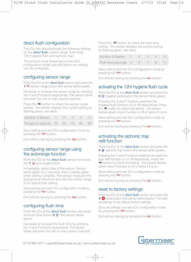
direct flush configurationThe ICU can adjust/activate the following settingson the direct flush: sensor range; flush time;12hr hygiene flush and siphonic trap.
The product must always be put into ICUconfiguration mode (see left) before any settingcan be configured.
configuring sensor rangePoint the ICU at the direct flush sensor and press the1 sensor range button (the sensor blinks green).
Decrease or increase the sensor range by pressingthe and buttons respectively. The sensor blinksred when the min or max value is reached.
Press the button to check the sensor rangesetting - the sensor displays the current setting byflashing green, see table.
Save setting and exit ICU configuration mode bypressing the button.
Exit without saving by pressing the button.
configuring sensor range usingthe autorange functionPoint the ICU at the direct flush sensor and pressthe 7 autorange button.
Immediately stand clear of the sensor. Sensorblinks green for 5 seconds, then a steady greenwhen setting complete. The sensor measures thebackground reflections and sets the sensor rangeto an appropriate setting.
Save setting and exit ICU configuration mode bypressing the button.
Exit without saving by pressing the button.
configuring flush timePoint the ICU at the direct flush sensor and pressthe flush time button 2 (the sensor blinksgreen).
Decrease or increase the flush time by pressingthe and buttons respectively. The sensorblinks red when the min or max value is reached.
Press the button to check the flush timesetting - the sensor displays the current settingby flashing green, see table.
Save setting and exit ICU configuration mode bypressing the button.
Exit without saving by pressing the button.
activating the 12hr hygiene flush cyclePoint the ICU at the direct flush sensor and press the5 hygiene cycle button (the sensor blinks green).
Pressing the and buttons switches thehygiene flush function on or off respectively. Pressthe button to check the setting - the sensorflashes green once if function is off or twice if it is on.
Save setting and exit ICU configuration mode bypressing the button.
Exit without saving by pressing the button.
activating the siphonic traprefill functionPoint the ICU at the direct flush sensor and press the8 siphonic trap button (the sensor blinks green).
Pressing the and buttons switches the siphonictrap refill function on or off respectively. Press the
button to check the setting - the sensor flashesgreen once if function is off or twice if it is on.
Save setting and exit ICU configuration mode bypressing the button.
Exit without saving by pressing the button.
reset to factory settingsPoint the ICU at the direct flush sensor and press the9 reset button (the sensor blinks green). This setsall settings to the default factory settings.
Save all settings and exit ICU configuration modeby pressing the button.
Exit without saving by pressing the button.
Number of flashes 1 2 3 4 5
Range (cm approx) 45 50 53 56 58
Number of flashes 1 2 3 4 5
Flush time (seconds) 3 5 7 9 11
31198 Direct Flush Installation Guide 25_6:18362 Sensazone Insert 2/7/13 10:28 Page 14
0118 969 1611 | [email protected] | www.cistermiser.co.uk
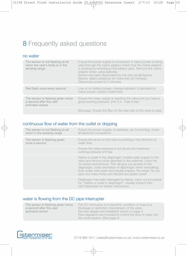
8 Frequently asked questions
no waterThe sensor is not flashing at all Ensure the power supply is connected. If mains power is beingwhen the user’s body is in the used through the mains adaptor check that the mains adaptorsensing range is working by reverting to the battery pack. Remove the mains
adaptor when using batteries.Sensor has been deactivated by the anti-vandal feature.(Sensor detect presence for more than 30 minutes).Disconnect power for 2 minutes.
Red flash once every second Low or no battery power; change batteries. If operated bymains power, contact Cistermiser.
The sensor is flashing green twice Ensure the water supply is reaching the valve and you have aa second after the user good working pressure. (min 0.5 - max 6 bar).activates sensor
Blockage. Ensure the filter on the inlet side of the valve is clear.
continuous flow of water from the outlet or drippingThe sensor is not flashing at all Ensure the power supply, or batteries, are functioning: checkwhen in the sensing range all electrical connections.
The sensor is flashing green Ensure the arrow on the valve is pointing in the direction ofonce a second water flow.
Ensure the water pressure is not above the maximumworking pressure of 6 bar.
Debris or scale in the diaphragm: isolate water supply to thevalve and remove wires attached to the solenoid. Undo the4x screws and remove. This will give you access to thediaphragm, (note orientation of diaphragm when reinstalling),flush under cold water and visually inspect. Re-install. Do notopen too many times and discard any plastic swarf.
Diaphragm has been damaged by debris. Carry out procedurefor. "Debris or scale in diaphragm”, visually inspect thencall Cistermiser for further instructions.
water is flowing from the DC pipe interrupterThe sensor is flashing green twice The DC interrupter is in backflow condition or there is aa second after the user blockage or restriction downstream of the valve.activates sensor See key design and installation points on page 4
Flow regulators are included to control the flow of water intothe urinal system. (See page 4)
31198 Direct Flush Installation Guide 25_6:18362 Sensazone Insert 2/7/13 10:28 Page 15
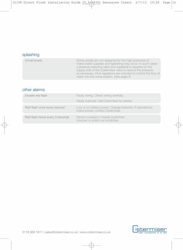
other alarmsDouble red flash Faulty wiring. Check wiring carefully.
Faulty solenoid. Call Cistermiser for advice.
Red flash once every second Low or no battery power. Change batteries. If operated bymains power, contact Cistermiser.
Red flash twice every 3 seconds Sensor covered or heavily scratched.Uncover or polish out scratches.
0118 969 1611 | [email protected] | www.cistermiser.co.uk
splashingUrinal bowls Some urinals are not designed for the high pressures of
mains water supplies and splashing may occur. In such casesa pressure reducing valve (not supplied) is required on thesupply side of the Cistermiser valve to reduce the pressureas necessary. Flow regulators are included to control the flow ofwater into the urinal system. (See page 4)
31198 Direct Flush Installation Guide 25_6:18362 Sensazone Insert 2/7/13 10:28 Page 16
0118 969 1611 | [email protected] | www.cistermiser.co.uk
DF27 B-01
cistermiser product warranty and extended warrantyCistermiser products are guaranteed fortwelve months from the date of manufacture.The guarantee is for faulty products and partsonly: there is no labour warranty. If you believeyour product is faulty, please either contactCistermiser directly on 0118 969 1611 orat [email protected], with aphotograph and the serial number, to diagnosethe cause of the problem.
The warranty on Cistermiser products can beextended, within one year of date of manufacture,at no cost to three years from the date ofinstallation by completing the enclosed warrantycard or at www.cistermiser.co.uk/warranty.Please make a note of the serial number andtake a photograph of the installation before youleave site.
31198 Direct Flush Installation Guide 25_6:18362 Sensazone Insert 2/7/13 10:27 Page 1