
Direct Fired Oxy-Fuel Combustor for sCO2 Power Cycles Library/Events/2017/utsr/track2... · Direct...
43
Direct Fired Oxy-Fuel Combustor for sCO2 Power Cycles Jacob Delimont, Ph.D. Nathan Andrews, Craig Nolen, Carolyn Day Southwest Research Institute Marc Portnoff Lalit Chordia, Ph.D. Thar Energy L.L.C. Wenting Sun, Ph.D. Georgia Tech Subith Vasu, Ph.D. UCF Sarah Monahan, Ph.D. Keith McManus, Ph.D. GE-GRC Work supported by US DOE under DE-FE002401 11/2/2017 2017 University Turbine Systems Research Workshop 1 HEAT SOURCE PRECOOLER LOW TEMP RECUPERATOR HIGH TEMP RECUPERATOR EXPANDER COMPRESSOR RE-COMPRESSOR P6 P7a P8 P1 P2 P3 P5 P7b P7 P4 P4b COOLING OUT COOLING IN P4a
-
Upload
hoanghuong -
Category
Documents
-
view
220 -
download
0
Transcript of Direct Fired Oxy-Fuel Combustor for sCO2 Power Cycles Library/Events/2017/utsr/track2... · Direct...

Direct Fired Oxy-Fuel Combustor for sCO2 Power Cycles
Jacob Delimont, Ph.D.Nathan Andrews, Craig Nolen, Carolyn Day
Southwest Research Institute
Marc PortnoffLalit Chordia, Ph.D.Thar Energy L.L.C.
Wenting Sun, Ph.D.Georgia Tech
Subith Vasu, Ph.D.UCF
Sarah Monahan, Ph.D. Keith McManus, Ph.D.
GE-GRC
Work supported by US DOE under DE-FE002401
11/2/2017 2017 University Turbine Systems Research Workshop 1
HEAT SOURCE
PRECOOLER
LOW TEMP RECUPERATOR
HIGH TEMPRECUPERATOR
EXPANDER
COMPRESSOR
RE-COMPRESSOR
P6 P7a P8
P1
P2
P3
P5
P7b
P7
P4
P4b
COOLING OUT COOLING IN
P4a

Outline
• Background• Project Objectives• Data From Bench Top Test• Combustor Design• Test Loop Design• Future Work
11/2/2017 2017 University Turbine Systems Research Workshop 2
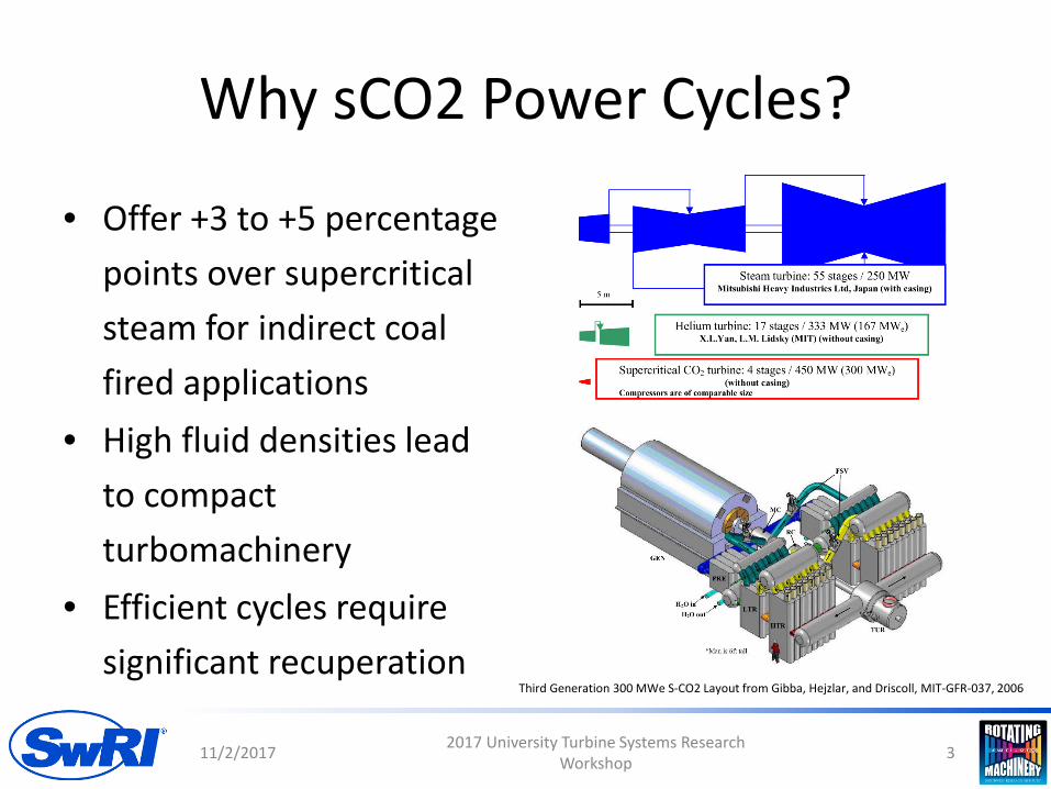
Why sCO2 Power Cycles?
• Offer +3 to +5 percentage points over supercritical steam for indirect coal fired applications
• High fluid densities lead to compact turbomachinery
• Efficient cycles require significant recuperation
11/2/2017 2017 University Turbine Systems Research Workshop 3
Third Generation 300 MWe S-CO2 Layout from Gibba, Hejzlar, and Driscoll, MIT-GFR-037, 2006
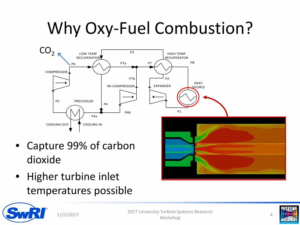
Why Oxy-Fuel Combustion?
11/2/2017 2017 University Turbine Systems Research Workshop 4
HEAT SOURCE
PRECOOLER
LOW TEMP RECUPERATOR
HIGH TEMPRECUPERATOR
EXPANDER
COMPRESSOR
RE-COMPRESSOR
P6 P7a P8
P1
P2
P3
P5
P7b
P7
P4
P4b
COOLING OUT COOLING IN
P4a
• Capture 99% of carbon dioxide
• Higher turbine inlet temperatures possible
CO2

ThermalInput
CoolerRecuperater
Turbine
Compressor
Pump
Oxy-Combustion
• Oxygen + fuel• Direct fired sCO2
combustors have a third inert stream
• Challenge:– Mix and combust fuel
without damaging the combustor
11/2/2017 2017 University Turbine Systems Research Workshop 5
Water Removal
Excess CO2 Removal
O2
Fuel
CO2 from Recuperator
CO2 + Water
Direct Fired Oxy-Combustor
Project Objectives
• Design a 1 MW thermal oxy-fuel combustor capable of generating 1200°C outlet temperature
• Manufacture combustor, assemble test loop, and commission oxy-fuel combustor
• Evaluate and characterize combustor performance – Optical access for advanced diagnostics
11/2/2017 2017 University Turbine Systems Research Workshop 6
Project Schedule
• Design Phase: 31 Dec 2017– Combustor design– Loop design
• Manufacturing construction and commissioning: 1 Jan. 2018 – 31 Dec. 2019
• Test and data collection: 1 Jan 2020 – 31 March 2021
11/2/2017 2017 University Turbine Systems Research Workshop 7
Outline
• Background• Project Objectives• Data From Bench Top Test• Combustor Design• Test Loop Design• Future Work
11/2/2017 2017 University Turbine Systems Research Workshop 8
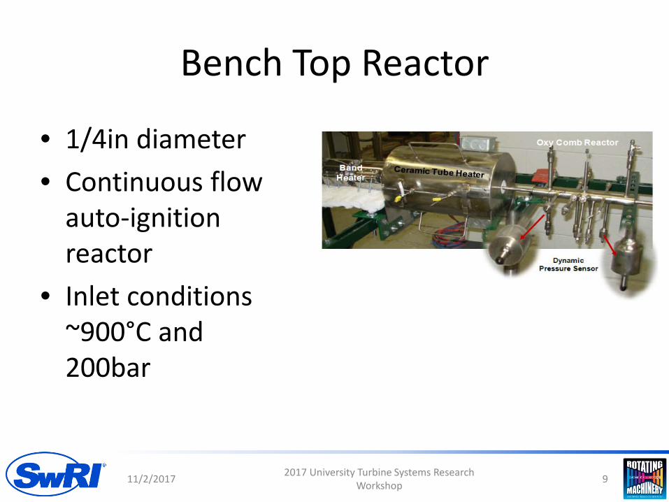
Bench Top Reactor
• 1/4in diameter• Continuous flow
auto-ignition reactor
• Inlet conditions ~900°C and 200bar
11/2/2017 2017 University Turbine Systems Research Workshop 9

Bench Top Reactor Temperature Profile
• Significant heat transfer within the reactor
• Auto-ignition occurred at a significantly lower temperature than expected
• Combustion zone temperature calculated based on a constant heat flux assumption
• Combustion zone temperature well below design temperature– Sufficient fuel and
oxidizer for 1100°C
11/2/2017 2017 University Turbine Systems Research Workshop 10

Results Discussion
• Fuel and oxidizer were sufficient to raise outlet temperature to ~1100°C
• Why didn’t it?– Mixing time– Chemical kinetics– Heat transfer and wall effects
• Auto ignition occurred at high concentrations of CO2 at ~620°C
11/2/2017 2017 University Turbine Systems Research Workshop 11

Outline
• Background• Project Objectives• Data From Bench Top Test• Combustor Design• Test Loop Design• Future Work
11/2/2017 2017 University Turbine Systems Research Workshop 12

Combustor Casing Design
Cooling CO2
FuelO2
CO2
Cooling CO2
700 °C
375 °C
1600 °C >1200 °C 400 °C
Cooling CO2
Cooling CO2
Pressure: 250 barTemperature: 375-700 °C
Cooling CO2

Reinforcement collar needed for hot CO2 center opening
• Calculated using ASME Section VIII Div. 1, UG-39• 3.4” OD, 2.375” ID, 4.25” long collar satisfies conditions and
minimizes interference with other lines
Fuel
Torch Ignitor
Oxygen
Gas Sampling Lines
TC’s
TC’s
Cooling CO2
Cooling CO2
11/2/2017 2017 University Turbine Systems Research Workshop 14

Inlet pipe will use a cooled-jacket liner to keep flange temperatures lower
Flange pair allows for access to removable liner
Inlet liner held in place using snap-ring or other method
Inlet liner extends into casing
Reinforcement integral to inlet pipe allows full penetration weld to flange
Cooling flow injection
11/2/2017 2017 University Turbine Systems Research Workshop 15
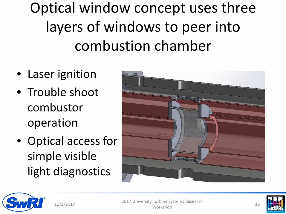
Optical window concept uses three layers of windows to peer into
combustion chamber
• Laser ignition• Trouble shoot
combustor operation
• Optical access for simple visible light diagnostics
11/2/2017 2017 University Turbine Systems Research Workshop 16
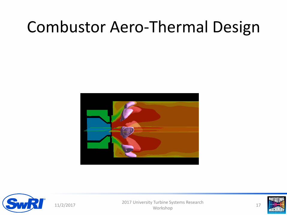
Combustor Aero-Thermal Design
11/2/2017 2017 University Turbine Systems Research Workshop 17

Kinetics Knowledge Base
11/2/2017 2017 University Turbine Systems Research Workshop 18
CO2 concentration
PressureCurrent Application
P up to 200 barxCO2 up to 0.96 (mostly as diluent)
Well-Developed MechanismsP up to 20 bar
xCO2 < 0.10 (mostly as product)Sparse data at low pressure, high CO2
Sparse data at high pressure, low CO2
Knowledge front
No data available at conditions relevant to this application.

Mechanisms are compared in a isobaric zero-dimensional reactor
19
554 °C 654 °C 754 °C 854 °C 954 °C
100 bar X
200 bar X X X* X X
300 bar X
Temperature vs. time results are presented for a range of temperatures and pressures
Mechanism CO2 O2 CH4 C2H6
Aramco 1.3, USC-II, Georgia Tech, and UCF 0.902 0.066 0.032 -
SwRI 6-species 0.903 0.066 0.029 0.0015
Nominal starting composition for each case (mole fractions)
• SwRI 6-species fuel quantity adjusted to match the adiabatic flame temperature of the USC-II case (that used pure methane)
* - High and low equivalence ratios also evaluated for this point
11/2/2017 2017 University Turbine Systems Research Workshop

T = 754°C, P = 200 bar, φ = 1.0
2011/2/2017 2017 University Turbine Systems Research Workshop
Computational Design
• Early design efforts constrained by high inlet temperatures needed to operate in a recompression cycle ~900°C combustor inlet
• Recuperator technology unlikely to be able to support those temperature in the near future
• Lower inlet temperature allow for easier design of submerged aerodynamic components
11/2/2017 2017 University Turbine Systems Research Workshop 21
New Explored Concept: Trapped vortex CFD setup
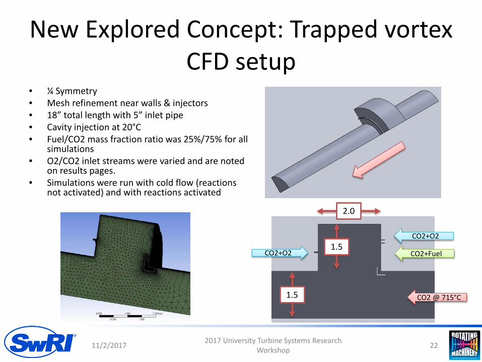
• ¼ Symmetry• Mesh refinement near walls & injectors• 18” total length with 5” inlet pipe• Cavity injection at 20°C• Fuel/CO2 mass fraction ratio was 25%/75% for all
simulations• O2/CO2 inlet streams were varied and are noted
on results pages.• Simulations were run with cold flow (reactions
not activated) and with reactions activated
11/2/2017 2017 University Turbine Systems Research Workshop 22
CO2 @ 715°C
CO2+O2
CO2+FuelCO2+O2
2.0
1.5
1.5

Trapped vortex combustor simulations: Sim ID: 501-502, 504
Cold Aft Injection
11/2/2017 2017 University Turbine Systems Research Workshop 23
25% O2; V=1 m/s
25% O2; V=1 m/s
CO2+Fuel; V=1 m/s
501: No Deflector 502: Deflector 504: Deflector

TVC Conclusion• The study performed agreed with the risks discussed in
the literature, in addition to the unknown risks of sCO2, specifically:– Combustor performance is sensitive to injector location
and injector velocity– Mechanical deflector/mixer required to enhance mixing
between cavity and main flow– Cooling walls and window visibility would also be another
source of risk. • The amount of risk has led to a halt in exploring this
technology. A more conventional design is now being explored
11/2/2017 2017 University Turbine Systems Research Workshop 24

Schematic of Combustor Design Concept
25
• Basis: DLN-1 primary fuel nozzle• Wide operability, stable flame, and extensive experience with this
design
CH4
CO2 +O2
Combustor
Dilution/cooling CO2
CO2 + O2
mixing element
Dilution/cooling CO2
CO2 +O2
11/2/2017 2017 University Turbine Systems Research Workshop

Range of CO2 Flow Splits to Primary Combustor & Bypass Cooling
26
Component Mass Flow (kg/s)
CH4 0.02
O2 0.08
CO2 to combustor 0.6 - 0.8
CO2 to bypass 0.925 – 0.725
Total mass flow 1.625
Aiming for Tadiabatic = 2700-3000 F for
flame stability
11/2/2017 2017 University Turbine Systems Research Workshop

Combustor Design Point
27
Component Mass Flow (kg/s)
CH4 0.02
O2 0.08
CO2 to combustor 0.626
CO2 to bypass 0.899
Total mass flow 1.625
• Design point for adiabatic flame temperature of 3000 F
• CO2 flow distributed as diluent or as bypass as shown above
• GE in-house spreadsheet tools used to determine effective area
and combustor size
11/2/2017 2017 University Turbine Systems Research Workshop

GE RANS Simulations
11/2/2017 2017 University Turbine Systems Research Workshop 28
GE LES Simulations
11/2/2017 2017 University Turbine Systems Research Workshop 29

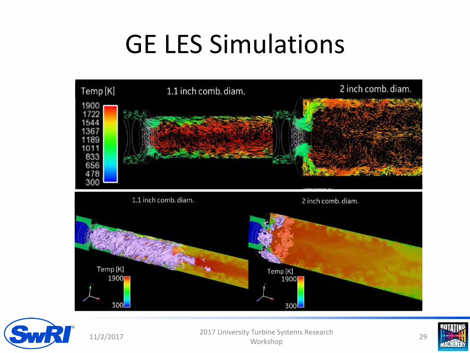
GE Results
• 2in diameter combustor performed significantly better than 1.1in diameter
• Further variations in combustor sizing/residence time to be considered
11/2/2017 2017 University Turbine Systems Research Workshop 30
SwRI RANS Simulations
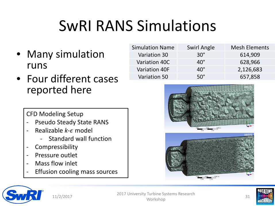
• Many simulation runs
• Four different cases reported here
11/2/2017 2017 University Turbine Systems Research Workshop 31
Simulation Name Swirl Angle Mesh ElementsVariation 30 30° 614,909
Variation 40C 40° 628,966Variation 40F 40° 2,126,683Variation 50 50° 657,858
CFD Modeling Setup- Pseudo Steady State RANS- Realizable k-𝜖𝜖 model
- Standard wall function- Compressibility- Pressure outlet- Mass flow inlet- Effusion cooling mass sources

Temperature Predictions
11/2/2017 2017 University Turbine Systems Research Workshop 32
30°
40° Coarse
40° Fine
50°

Flow Predictions
11/2/2017 2017 University Turbine Systems Research Workshop 33
30°
40° Coarse
40° Fine
50°
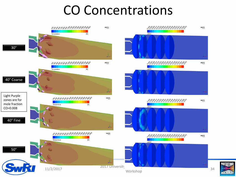
CO Concentrations
11/2/2017 2017 University Turbine Systems Research Workshop 34
Light Purple zones are for mole fraction CO=0.008
30°
40° Coarse
40° Fine
50°
Outline
• Background• Project Objectives• Data From Bench Top Test• Combustor Design• Test Loop Design• Future Work
11/2/2017 2017 University Turbine Systems Research Workshop 35
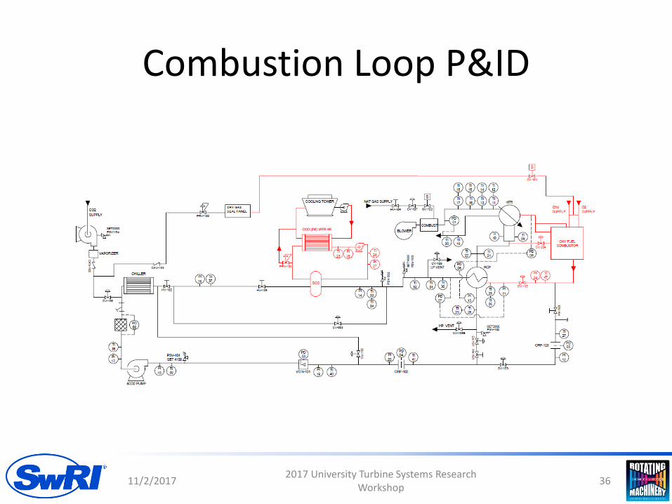
Combustion Loop P&ID
11/2/2017 2017 University Turbine Systems Research Workshop 36
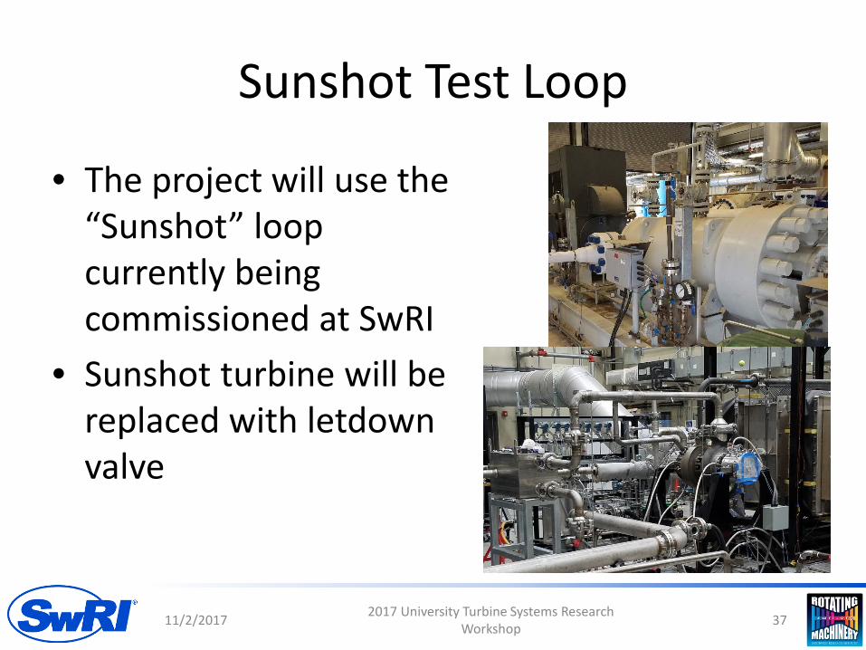
Sunshot Test Loop
11/2/2017 2017 University Turbine Systems Research Workshop 37
• The project will use the “Sunshot” loop currently being commissioned at SwRI
• Sunshot turbine will be replaced with letdown valve

Fuel Supply System
• Major challenge to supply oxygen to a 700°C flow
• Torch ignitor system
11/2/2017 2017 University Turbine Systems Research Workshop 38
Water Separation
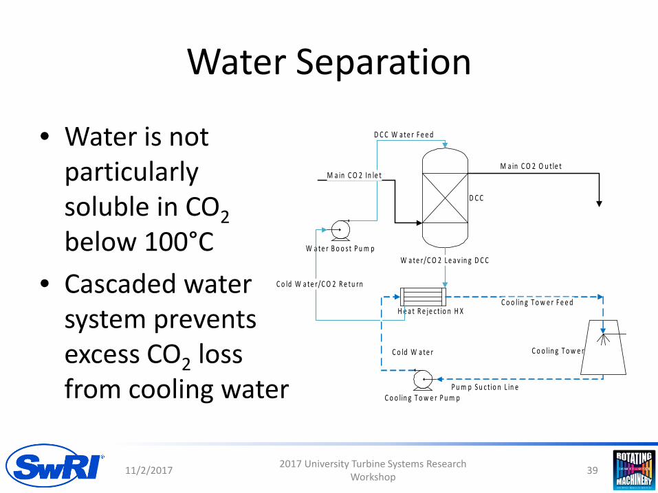
• Water is not particularly soluble in CO2below 100°C
• Cascaded water system prevents excess CO2 loss from cooling water
11/2/2017 2017 University Turbine Systems Research Workshop 39
W a te r B o o s t P u m p
D C C
H e a t R e je c t io n H X
C o o lin g T o w e r
D C C W a te r F e e d
W a te r/C O 2 L e a v in g D C C
M a in C O 2 In le tM a in C O 2 O u t le t
C o ld W a te r
C o ld W a te r/C O 2 R e tu rn
C o o lin g T o w e r F e e d
C o o lin g T o w e r P u m pP u m p S u c t io n L in e

Water/CO2 Equilibrium Testing
• Phase equilibrium test ongoing at Thar Energy
• Testing to confirm solubility limits of water in CO2
• Needed for modeling of water seperation
11/2/2017 2017 University Turbine Systems Research Workshop 40

Outline
• Background• Project Objectives• Data From Bench Top Test• Combustor Design• Test Loop Design• Future Work
11/2/2017 2017 University Turbine Systems Research Workshop 41
Next Steps
• Finalize combustor design– Heat transfer– Injector design– Optical access
• Finalize quotes on loop and fuel systems• Finalize combustor manufacturing plan
11/2/2017 2017 University Turbine Systems Research Workshop 42

QUESTIONS?
11/2/2017 2017 University Turbine Systems Research Workshop 43
ThermalInput


![SOFCOM Meeting M24 - areeweb.polito.it · Cleaning Unit Reforming Unit SOFC Stack Unit Oxy-combustor CO2 separation Unit ... Total flow rate [NLPM] 57 30 2 Available temperature [°C]](https://static.fdocuments.us/doc/165x107/5abfacb67f8b9a8e3f8e94bf/sofcom-meeting-m24-unit-reforming-unit-sofc-stack-unit-oxy-combustor-co2-separation.jpg)


