Direct Fired Make-Up Air Units - Modine
40
7-150.3 • MAY, 2015 DIRECT GAS-FIRED INDOOR AND OUTDOOR HEATING AND MAKE-UP AIR UNITS VERTICAL CONFIGURATION HORIZONTAL CONFIGURATION
Transcript of Direct Fired Make-Up Air Units - Modine
7-150.3 • MAY, 2015
Direct Gas-FireD inDoor anD outDoor HeatinG anD Make-up air units
vertical conFiGuration
Horizontal conFiGuration

Direct Fired Make-Up Air Units
2 7-150.3
Table of Contents PageFeatures and Benefits .......................................................................................................................................................... 3General Descriptions Model MDB - 100% Make-Up Air Units ............................................................................................................................ 4 Model MRB - Return Air Units........................................................................................................................................... 4Design Features ................................................................................................................................................................... 5General Performance Data .................................................................................................................................................. 6Model Nomenclature Description .................................................................................................................................... 7-10Options ...........................................................................................................................................................................11-12Accessories ................................................................................................................................................................... 12-13Air Control Applications - 100% Make-Up Air Units - Model MDB Air Control Types .......................................................................................................................................................... 14 Variable Air Volume Principles ...................................................................................................................................... 15Air Control Applications - Return Air Units - Model MRB ................................................................................................... 16Unit Selection Procedure............................................................................................................................................... 18-19Accessory Static Pressure Drop Data ........................................................................................................................... 20-21Blower Performance Data ............................................................................................................................................. 22-23Motor Sheave Assembly Data ............................................................................................................................................ 24Electrical Data .................................................................................................................................................................... 25Manifold Arrangements ...................................................................................................................................................... 26Unit and Accessory Weights .............................................................................................................................................. 27Unit and Accessory Dimensions Model MDB/MRB 110-118 Units - Horizontal ............................................................................................................... 28 Model MDB/MRB 120-130 Units - Horizontal ............................................................................................................... 29 Model MDB/MRB 220-230 Units - Horizontal ............................................................................................................... 30 Model MDB/MRB 110-118 Units - Vertical .................................................................................................................... 31 Roof Curbs .................................................................................................................................................................... 32 Service Platforms .......................................................................................................................................................... 33Evaporative Cooler Data .................................................................................................................................................... 34Evaporative Cooler Dimensions ......................................................................................................................................... 35Specifications ................................................................................................................................................................ 36-38Model Nomenclature .......................................................................................................................................................... 39
As Modine has a continuous product improvement program, it reserves the right to change design and specifications without notice.
Direct-fired make-up units are designed to provide an economical and efficient means of supplying tempered make-up air to a space or building. Any building with exhaust is a candidate for the application of a direct-fired make-up air unit to replace the exhausted air.
This catalog describes the design benefits, construction features, performance data, unit selection procedure, control applications, and the optional and accessory devices available for the direct-fired make-up air units.
WARNINGDo not locate ANY gas-fired unit in areas where chlorinated, halogenated or acid vapors are present in the atmosphere.
! WARNINGAppliances must not be installed where they may be exposed to a potentially explosive or flammable atmosphere.
!
Table of Contents

Direct Fired Make-Up Air Units
37-150.3
Profile
Line Burner
Centrifugal Fan(s)
Flame ObservationPort
Four Access Doors(2 Per Side)
Curb Adaptable Base
Adjustable Motor Sheaves
18 GaugeGalvanized SteelCasing
Control CabinetTool Access Draw Tight Fasteners
Optional Factory Mounted Deadfront Disconnect Switch
Gas ManifoldCompartment
Fuel Connection
Weatherproof Access Doors
Lifting Lugs
U.L. Recognized/ListedElectrical Components
Feature• Fuel efficient line burner with fixed profile .........................• Blower performance up to 3.0" W.C. .................................• Building management system compatible controls ............• Input range up to 7,425 MBH ............................................• Centrifugal fan(s) rated to 60,000 CFM .............................• ETL approved and certified. ...............................................
Benefit• 100% efficient (92% sensible), clean burning, low NOx• Applications with longer ductwork or high pressure drop accessories• Allows for maximum control flexibility• Flexibility to accommodate a variety of heating requirements • AMCA-rated fans assure quality and performance• Third-party agency certified to national safety standards in both the U.S.
and Canada (except model MRB which is not available in Canada)
Easy Installation/Service • Exterior fuel connection NPT pipe stub .............................• Adjustable motor sheaves ..................................................• Separate manifold and electrical control compartments ....• Tooled-access, draw-tight door fasteners ..........................• Deadfront main disconnect switch (Optional) ....................
• Terminal strip wiring ...........................................................• Four access doors (2 per side) ..........................................• Flame observation port ......................................................• U.L. recognized/listed electrical components ....................• Job specific wiring diagrams ..............................................
• Provides contractor/installer with easy connection point• Simplifies onsite air balancing• Isolated compartments allowing easy and unobstructed access• Discourages non-authorized access and assures positive seal• Saves labor time compared to mounting a box type switch and insures
power is deactivated when control cabinet is open
• Allows for quick and accurate field wiring connections• Provides maximum access for easy adjustments and service• Allows external observation of burner performance• Assures reliable and safe electrical components• Allows for easy installation/troubleshooting
Features and Benefits
Variable Frequency Drive (MDB Units Only) • Significant energy savings feature .....................................
• Reduced noise level ...........................................................• Stall prevention/overload protection ...................................• Reduced maintenance cost ...............................................
• Adjusting fan speed to meet air system needs allows substantial energy reductions compared to fixed-speed systems
• Reduced airflow noise reduces customer noise complaints• Reduced drive output during a temporary motor overload • Soft start reduces wear on motors, belts and system components

Direct Fired Make-Up Air Units
4 7-150.3
100% Makeup Air (MDB)For buildings requiring 100% make-up air, direct-fired units provide the best fuel efficiency (100% thermal efficiency, 92% sensible). The make-up air is heated directly by the gas flame, eliminating the need for a heat exchanger and associated efficiency losses of indirect-fired equipment. Model MDB units provide maximum application flexibility with input ratings up to 7,425,000 Btu/hr and maximum airflow capability of 60,000CFM.Model MDB units are available with various types of motor control:• Single speed blower motor for constant volume application.• Variable frequency drive (VFD) two-speed control for operation
where the VFD will be factory programmed for a single customer specified low speed airflow with high-speed operation at 100% of rated airflow.
• Variable frequency drive (VFD) building pressure control ideal for constantly varying exhaust fan loads.
For units with VFD variable air volume control, in addition to makeup air volume flexibility, substantial electrical savings can be achieved by reducing motor horsepower requirements during reduced loading periods (please see Variable Air Volume Principles on page 15 for additional details).
Return Air Units (MRB)Direct-fired units can be used as combination make-up air and heating/ventilating units, requiring the capability of operating with recirculated air as well as make-up air. Model MRB units provide maximum application flexibility with input ratings up to 5,500,000 Btu/hr, maximum airflow capability of 41,000CFM and maximum return air capability of 75% With direct-fired MRB units, a minimum 25% outside air must always be supplied to the building.There are two types of return air control available:• Two-position fixed return air units operate either in maximum
return air mode (75% or 70% return air) or 100% outside air mode. These units are provided with two-position burner by-pass and return air damper.
• Floating position return air units operate by automatically and continually varying the percentage of return air and outside air (from 0% to a maximum of 75% return air) to provide makeup air for a varying exhaust fan load. The units are provided with a set of floating burner by-pass and return air dampers, controlled by means of a building air pressure switch.
For floating control applications, variable frequency drive 30-100% variable air volume control units (Model MDB) provide an excellent alternative to MRB units with floating controls. Please see Variable Air Volume Principles on page 15 for a discussion of the substantial electrical savings that can be achieved with a MDB unit with variable frequency drive control.
➀ Inlet hood (opt.)➁ Inlet dampers (opt.)➂ Burner by-pass dampers➃ Burner➄ Return air dampers➅ Blower
S/A
O/A
32
1 4
➀ Inlet hood (opt.)➁ Inlet dampers (opt.)➂ Burner➃ Blower
100%
Figure 4.1 - 100% Makeup Air Unit (MDB)
General Description
Figure 4.2 - Return Air Unit (MRB)

Direct Fired Make-Up Air Units
57-150.3
Design Features - 100% Make-Up Air and Return Air UnitsStandard Features• ETL Certification• IRI compliant manifold assemblies (FM available)• 100% Thermal Efficiency, (92% sensible)• Natural or propane manifolds• 18 gauge galvanized steel cabinet (paint optional) with
insulated burner and blower sections• Outdoor units designed for roof curb or slab mounting, indoor
units designed for slab or suspension mounting• Four (4) full access service doors• Separate manifold and electrical controls compartments• Numbered terminal strip wiring and job specific wiring diagram
for ease of field wiring• Permanent lifting/mounting lugs• Model sizes 110 through 118 have a single double-width,
double-inlet (DWDI) blower wheel with spider bearings (pillow block bearings optional)
• Model sizes 120 through 130 have a single DWDI blower wheel with pillow block bearings
• Model sizes 220 through 230 have twin DWDI blowers with pillow block bearings
• Motors include adjustable motor sheaves• Maxitrol 14 discharge air temperature controls (other control
system options available)• Flame rod flame supervision • High and low airflow proving switches• High limit switch• Flame failure lockout relay
Optional Features - Factory Installed• Painted unit casing• Inlet hood, unpainted (paint optional) with or without filters (field
installed for Model sizes 125 and above)• Insulated V-bank 2” filter section, unpainted (paint optional) with
permanent, throwaway, or Farr 30/30 (field installed for Model sizes 125 and above and vertical units)
• Inlet damper, unpainted (paint optional) (field installed for Model sizes 125 and above and vertical units)
• Pillow block bearings on Model sizes 110 through 118• Internal spring blower and motor vibration isolation (requires
pillow block bearings)• Extended grease lines (requires pillow block bearings)• Deadfront fused disconnect switch• High and low gas pressure switches• Building management system control options• Control power transformer to 115V from 208, 230 or 460v
supply voltages • Timed freeze protection• Mild temperature inlet on/off duct stat• Motor starter auxiliary contacts for starting exhaust fan (starter
circuit by others) (single speed motor starters only)• Double Pole Double Throw (DPDT) control relays• Circuit analyzer for 10 or 12 points
Accessory Features - Field Installed• NEMA 1 remote control panels• Discharge dampers, unpainted (paint optional)• Discharge louvers (3 or 4 way), unpainted (paint optional)• Evaporative cooler with pre-filters (optional rainhood with pre-
filters) with 12” Celdek or Glasdek media• Evaporative cooler fill and drain kits, manual or automatic with
optional freeze stat• Inlet stand, painted in 24" or 48" heights, with or without inlet
screen (vertical units only)• Vibration hangers for suspended units• Vibration feet for slab mounted units• Box style disconnect switch

Direct Fired Make-Up Air Units
6 7-150.3
General Performance DataTable 6.1 - General Performance Data
➀ See blower performance data on pages 34-35 for available total static pressure drop capability.➁ ETL certified maximum allowable discharge air temperature is 105°F. Maximum air temperature
rise is 115°F for Natural Gas, 100°F for LP Gas.➂ Maximum Btu/hr based on max CFM and temp rise with -30°F entering air. Actual max Btu/hr may
be lower depending on job conditions. ➃ CFM shown is with -10°F outside air with a 100°F air temperature rise. Actual capability may vary
with different conditions. Please refer to the AccuSpec software with your conditions.➄ Model Size 124 is available only for 100% outside air applications.
Model Size
Min CFM (All Units)
Model MDB Units Model MRB Units
Max CFM Max Input Btu/hr ➂
Max CFM (75/25) ➃
Max CFM (70/30) ➄
110 1,600 3,300 432,400 3,000 3,000112 2,000 4,700 615,800 4,380 4,500115 3,000 6,500 851,700 6,000 6,000118 3,500 10,000 1,310,300 6,190 6,630120 6,000 13,500 1,769,000 12,000 12,000122 8,000 16,500 2,162,100 12,980 13,900124 10,000 21,500 2,162,100 n/a ➄ n/a ➄125 10,000 21,500 2,817,300 20,000 20,000127 12,000 26,000 3,406,900 23,260 24,000130 14,000 30,000 3,931,100 23,260 24,920220 18,000 27,000 3,538,000 25,345 26,000222 25,000 33,000 4,324,200 25,345 27,155225 30,000 46,000 6,027,700 38,685 41,450230 36,000 60,000 7,862,200 38,685 41,450

Direct Fired Make-Up Air Units
77-150.3
Model Nomenclature DescriptionDigits 1-2 - Unit TypeMD = 100% makeup air unit for single speed, two speed variable
frequency drive (VFD), or modulating VFD applicationsMR = Outside and return air unitDigit 3 - Development SequenceUsed internally to indicate the product generation.B = All current units
Digit 4,5,6 - Blower Wheel Quantity and DiameterTo determine the proper blower size, review the blower performance tables for the desired model size and insure that the required CFM and total static pressure (internal static pressure + external static pressure) are within the range selected. For additional information on determining the proper blower size, review the Sizing and Selection Example on pages 18 and 19.
110 = (1) – 10” blower wheel112 = (1) – 12” blower wheel115 = (1) – 15” blower wheel118 = (1) – 18” blower wheel120 = (1) – 20” blower wheel122 = (1) – 22” blower wheel124 = (1) – 25" x 22" blower wheel
Digit 7 - Unit ConfigurationDetermines the casing orientation and controls access side. The control side is determined by looking into the intake of the unit and then specifying the access side (right or left hand). Includes access to gas manifold compartment and electrical control wiring compartment.A = Horizontal, right access, straight discharge (bottom return on MR)B = Horizontal, left access, straight discharge (bottom return on MR)C = Horizontal, right access, bottom discharge (bottom return on MR)D = Horizontal, left access, bottom discharge (bottom return on MR)E = Horizontal, right access, top discharge (not available on MR)F = Horizontal, left access, top discharge (not available on MR)G = Vertical, right access, top discharge (not available on MR)J = Vertical, right access, top-right discharge (not available on MR)
Digit 8 - Cabinet Finish and Installation LocationCasings can be provided as either unpainted G90 galvanized or painted. Both can be specified for either indoor or outdoor installation. Casing is insulated with 1", 1-1/2 lb. density insulation as standard.A = Unpainted, Outdoor InstallationB = Unpainted, Indoor InstallationC = Painted, Outdoor InstallationD = Painted, Indoor Installation
Digit 9,10,11,12 - Maximum Burner Input (MBH)Manifold assemblies are sized with burner lengths in 6” increments at 275MBH per 6” increment. The model number will reflect the maximum rating for the selected burner length.Example:
Unit is to be sized for a firing rate of 1750MBH. A burner length of 36” has a maximum firing rate capability of 1650MBH (6 x 275MBH), while a 42” burner has a maximum firing rate capability of 1925MBH (7 x 275MBH). While the unit will be designed for a firing rate 1750MBH, Digits 9-12 of the model number will reflect 1925. (1650MBH would be too small).
Digit 13 - Gas Type and Inlet PressureSpecifies the gas type and gas inlet pressure being used. A = Natural Gas (8-14”) B = Natural Gas (1-5 psi) ➀C = Propane Gas (11-14”) D = Propane Gas (1-5 psi) ➀➀ Available for manifolds over 720MBH only (Digits 9-12 = 0825 or
above). For applications with 1-5 psig gas pressure on units with Digits 9-12 = 0275, 0400, 0550 or 720, use a manifold rated for either 8-14" W.C. (natural gas) or 11-14" W.C. (propane gas) and install a field supplied step-down pressure regulator accessory.
Digit 14 - Gas Control SystemThe gas control system controls the burner firing rate of the unit. All gas controls offered feature electronic modulation. A = Maxitrol System 14System 14 features a remote temperature dial for adjusting the discharge air temperature set point and a field mounted and wired discharge air sensor and controls an electronic modulating gas valve which modulates the main burner gas flow to maintain the desired discharge air temperature. The temperature set point range for this system is 55-90°F.This system can be used with an accessory room temperature override thermostat. The stat automatically overrides the discharge air temperature setting by 15°F to provide warmer discharge air until the room override stat is satisfied.
For MRB units, also included are outside air and return air low limit stats. If the temperaure being monitored falls below the factory set point, the dampers open to 100% outside air and remain in that position until the low temperature condition is cleared for both low limit stats. Please refer to Table 8.1 for additional guidance.
➀ Configurations shown facing the side with the gas and electrical controls.➁ Return air opening for Model MRB.
Figure 7.1 - Unit Configurations ➀
2
A = HRS B = HLS
2
C = HRB
2
D = HLB
2
F = HLT
5
A = HRS
Denotes direction of air flow
E = HRT
G = VTS J = VTR
125 = (1) – 25” blower wheel127 = (1) – 27” blower wheel 130 = (1) – 30” blower wheel 220 = (2) – 20” blower wheels222 = (2) – 22” blower wheels225 = (2) – 25” blower wheels230 = (2) – 30” blower wheels

Direct Fired Make-Up Air Units
8 7-150.3
Model Nomenclature DescriptionB = Maxitrol System 44System 44 features a modulating room thermostat to control the main burner firing rate based on the room air temperature set point. The temperature set point range for this system is 55-90 degrees F.This control system also includes a field mounted and wired discharge air sensor, which is used as a high and low temperature limit control. The discharge air sensor will prevent make-up air from being delivered to the space at temperatures below the low setpoint, even if the room thermostat is satisfied. It will also prevent the room thermostat from over firing the burner when mild outdoor temperatures exist and the maximum firing capacity of the burner is not required to achieve an appropriate discharge air temperature.For MRB units, also included are outside air and return air low limit stats. If the temperaure being monitored falls below the factory get point, the dampers open to 100% outside air and remain in that position until the low temperature condition is cleared for both low limit stats. Please refer to Table 8.1 for additional guidance.
Maxitrol SC10 for DDC Compatibility (C = 4-20mA control or D = 0-10VDC control)The DDC compatible control system utilizes a 4-20mA or 0-10VDC input signal (by others) to control the discharge air temperature. This system requires a field supplied air temperature sensor that is compatible with the building management system. This sensor is wired to the building management system and based on the temperature reading from that thermostat, the building management system will increase or decrease the signal to the makeup air unit gas controls.Provided with this system is a discharge air sensor high temperature limit control. The discharge air sensor will prevent make-up air being delivered to the space that is above the operating limit of 105°F.For MRB units, also included are outside air and return air low limit stats. If the temperaure being monitored falls below the factory get point, the dampers open to 100% outside air and remain in that position until the low temperature condition is cleared for both low limit stats Please refer to Table 8.1 for additional guidance.
Gas Control Selection Table for Model MRB UnitsTable 8.1 is to be used for Model MRB units only to determine applicability of the various available gas control systems to meet requirements of ETL certification and ANSI Z83.18. For additional information on these control systems, please see Gas Control Descriptions above.
Table 8.1 - Gas Control System Selection Table for Model MRB
➀ Minimum return air temperature is 55°F. For return air temperatures below 55°F, please contact the factory.➁ Room override accessory can override discharge air setting by 15°F to a maximum discharge air temperature of 105°F.
Gas Control System
RA/OA Ratio
Minimum Outside Air Temperature (per ASHRAE) �
MaximumDischarge Air Temperature
Room Override
Maxitrol 1475/25 -30°F and Above
90°F Not Available70/30 -30°F to Lower than 10°F70/30 10°F and Above 90°F � Accessory
Maxitrol 4475/25
-30°F to Lower than -10°F 90°F
Not Applicable
-10°F to Lower than 0°F 95°F0°F and Above 100°F
or70/30
-30°F to Lower than -20°F 95°FMaxitrol SC11 -20°F to Lower than -10°F 100°F
-10°F and Above 105°F

Direct Fired Make-Up Air Units
97-150.3
Model Nomenclature DescriptionDigit 15 - InsuranceAll standard manifold arrangements are ETL certified to meet the ANSI standards for direct fired makeup air heaters. As standard, the manifolds also meet the requirements of IRI (Industrial Risk Insurers) for all manifold sizes.Optional manifold arrangements are available to meet the requirements of FM (Factory Mutual), “with restriction” or “less restriction”. The arrangement for “with restriction” is the most common and is required anytime there is a restriction on the inlet of the unit. Restrictions include filters, inlet dampers, etc.1 = IRI (standard ETL)2 = FM less Restriction3 = FM with Restriction
Digit 16 - Additional Manifold OptionsA low gas pressure switch monitors the gas supply pressure upstream of all the gas controls and disables the gas controls if low gas pressure is experienced. This will shut off all gas flow to the burner to avoid the burner from having difficulty lighting properly or maintaining a proper flame.A high gas pressure switch monitors the gas supply pressure downstream of all the gas controls and disables the gas controls if high gas pressure is experienced immediately before the burner. This will shut off all gas flow to the burner to avoid the gas controls from being damaged or causing the unit to over fire.Both the low and high gas pressure switches are manual reset so that a service person must inspect the unit to make sure that none of the gas controls have been damaged. The switch must then be reset to allow the unit to operate when the gas conditions are returned to the normal operating pressure.C = High & Low Gas Pressure SwitchN = None
Digit 17 - Air Control OptionsDetermines the control package for the unit sequence of operation.Digit A for single speed 100% makeup air applications is simply continuous operation when on, normally controlled via a Summer/Off/Winter switch.For detailed sequence of operation descriptions on all Air Control Options other than Digit 17=A, please see pages 14 through 17.A = 100% MUA - Single SpeedB = 100% MUA - Two Speed (VFD) - Type AC = 100% MUA - Two Speed (VFD) - Type BD = 100% MUA - DDC Control (VFD only) - Type AE = 100% MUA - DDC Control (VFD only) - Type BF = Space Pressure Control (MD with VFD or MR) - Type AG = Space Pressure Control (MD with VFD or MR) - Type BH = Space Pressure Control (MD with VFD or MR) - Type CI = Return Air - Fixed 75/25 Dampers - Type AJ = Return Air - Fixed 75/25 Dampers - Type BK = Return Air - Fixed 75/25 Dampers - Type CL = Return Air - Fixed 70/30 Dampers - Type AM = Return Air - Fixed 70/30 Dampers - Type BN = Return Air - Fixed 70/30 Dampers - Type C
Digit 18 - Supply VoltageIndicates the supply voltage for the unit. A step down transformer may be required to reduce the supply voltage to 115V for the unit controls. Please see page 12 for additional information on the control transformer option.1 = 115V/60Hz/1Ph 5 = 230V/60Hz/3Ph2 = 208V/60Hz/1Ph 6 = 460V/60Hz/3Ph3 = 230V/60Hz/1Ph 7 = 575V/60Hz/3ph (MDB only)4 = 208V/60Hz/3Ph
Digit 19 - Bearings and Vibration IsolationA = Spider Bearings (No Vibration Isolation)Spider bearings include blower mounted bearing brackets with permanently lubricated ball bearings. Spider bearings are designed for use in low motor horsepower applications and are standard for all single speed model MDB unit sizes 110-118.B = Pillow Block Bearings (No Vibration Isolation)Pillow block bearings include heavy-duty pillow block bearing housings with greasable internal ball bearings that are rigidly fastened to two 18 gauge minimum blower support channels. Pillow block bearings are optional on model MDB single speed unit sizes 110-118 and standard on all other MDB models and on all MRB models.C = Pillow Block Bearings (With Spring Vibration Isolation)Spring vibration isolation is available for units with pillow block bearings. This feature provides an independent blower and motor mounting frame that is supported in each corner by a 1” deflection spring isolator. Only available on units with Digit 7=A, B, C, or D and not available on 124 size units.For pillow block bearings, extended grease lines are available as an option to allow for greasing of the bearings from outside the unit cabinet. Please see page 11 for additional information on this option.For suspended or slab mounted units, vibration hangers or feet may be a more cost-effective solution than spring vibration isolation. Please see Vibration Hangers or Vibration Feet in the Accessories section.

Direct Fired Make-Up Air Units
10 7-150.3
Model Nomenclature DescriptionDigit 20 - Motor Horsepower (HP)The required motor horsepower is determined by the required CFM and total static pressure (internal static pressure + external static pressure) from the blower performance data. For additional information on selecting the proper motor horsepower, review the Sizing and Selection Example on pages 18 and 19. Refer to pages 22 through 23 for blower performance data.All units (except MDB units with a variable frequency drive) include a factory installed motor starter with overload protection as standard. For MDB units with a VFD, a motor starter is not necessary and therefore not included. A = 3/4 H = 10B = 1 I = 15C = 1 1/2 J = 20D = 2 K = 25E = 3 L = 30F = 5 M = 40G = 7 1/2 N = 50 Digit 21 - Motor TypeBlower motors are available in Open Drip Proof (ODP), Totally Enclosed (TE), and NEMA Premium Efficiency ODP or TE. All motors are continuous duty, ball bearing type, minimum Class “B” insulated with a rigid base. Motors rated 1HP and larger that are 3 phase are inverter duty motors. For the list of available motors based on supply voltage, refer to page 25.Where applicable, all motors meet the requirements of the Energy Independence and Security Act of 2007.1 = ODP 5 = TE2 = ODP - High Efficiency 6 = TE - High Efficiency Digit 22 - Sheave ArrangementAll units are provided with adjustable motor sheaves so that the blower rpm can be adjusted for slight increases or decreases in the actual job external static pressure as compared to the design external static pressure. The adjustment range of the adjustable sheaves is shown in the Sheave Selection Tables on page 24.
Digit 23 - Profile AssemblyUsed for internal factory purposes to indicate the burner profile assembly to be included with the unit. The burner profile is fixed at the factory to provide the proper air velocity across the burner for proper combustion.

Direct Fired Make-Up Air Units
117-150.3
OptionsThe following list details the available options, factory installed (unless otherwise noted).
Extended Grease Lines (Requires Pillow Block Bearings)Includes factory installed grease lines extending from the blower bearings to the outside of the unit cabinet. Also includes Zerk fittings for applying grease. Requires grease for initial start-up.
V-Bank Filter SectionUsed to filter outside air drawn through the unit. Available either painted or unpainted. The section is available with several filter configurations:• With 2” permanent, aluminum mesh washable filters• With 2” FARR 30/30 filters• With 2” throwaway 30% filtersFor horizontal unit sizes 110-124, the V-bank filter section is factory installed to the unit. For all other model sizes, the section is fully assembled but shipped loose for field installation.All V-bank filter sections require additional support when installed. Please see Inlet Hood and/or V-Bank Roof Support in the Accessories section for additional details.Inlet DamperUsed to prevent the building air from exiting the building through the unit when the unit is not operating. Includes a factory installed 2-position damper motor (unit sizes 220-230 include two 2-position damper motors). The damper motor includes an end switch to prevent unit operation unless the dampers are open. The inlet damper is available either painted or unpainted.For horizontal unit sizes 110-124, the inlet damper is factory installed to the unit (or V-bank filter section if selected). For all other model sizes, the inlet damper is fully assembled but shipped loose (or to V-bank filter section if selected) for field installation.Field installed discharge dampers are available. Please see Accessories section for additional details. Note that only inlet dampers or discharge dampers should be selected, not both.Inlet Hood (Horizontal units only)Used to prevent entry of rain into the fresh air opening of the unit and includes meshed bird screen on opening. Available either painted or unpainted and with or without 2” permanent aluminum mesh washable filters. Inlet hood is factory assembled.For outdoor units, sizes 110-124, the inlet hood is factory installed to the unit (or V-bank filter section or inlet damper, if selected). For outdoor units, sizes 125-222, the inlet hood is factory installed to the V-bank filter section or inlet damper, if selected, otherwise shipped loose for field installation. For outdoor units, sizes 225-230, the hood is shipped separate for field installation. For all indoor units, the hood is shipped separate for field installation at the entry to the building.All hoods require additional support when installed. Please see Inlet Hood and/or V-Bank Roof Support in the Accessories section for additional details.
Timed Freeze ProtectionIncludes a low limit discharge duct stat and a freeze protection timer. The duct stat monitors the discharge air temperature. On initial start-up, the timed delay in the system allows the unit to go through the normal ignition sequence. The timed delay is an automatic reset switch. In the event that the unit fails to fire after this period, the discharge air sensor will sense the cold air and will shut down the entire unit.Mild Temperature Inlet On/Off Used to automatically shut off the burner when the inlet air temperature reaches the desired setpoint to prevent the burner from continually running at low fire during mild outdoor air temperature conditions.Exhaust Fan Interlock ContactsAn auxilary contact on the motor starter can be used to start an exhaust fan starter circuit (by others) whenever the unit is running. Available only on single speed units. DPDT Interlocking Relay option (see option below) should be used for additional contacts.To start exhaust fans from VFD equipped units, a DPDT Interlocking Relay (see option below) should be added.For 2-position return air units that are to start an exhaust fan in the 100% outside air mode, a DPDT Interlocking Relay (see option below) should be added rather than an exhaust fan interlock contact.
DPDT Interlocking RelayAn interlocking relay can be used to control any number of different functions. The most common function is to start an exhaust fan. Each relay has two sets of normally open and normally closed contacts. If the function of the relay is other than starting an exhaust fan, the function must be specified on the order.Service Door Interlock Switch automatically breaks power in the unit when the service door is opened. For each door that is to be interlocked, one switch must be ordered. Available on Electrical Compartment, Piping Compartment, Blower Compartment, and/or Burner Compartment doors.Convenience OutletIncludes a 115V/1ph duplex service receptacle mounted in the piping compartment. Requires a separate field connected 115V power supply.Deadfront Fused Disconnect SwitchFactory installed in the door of the electrical control compartment, includes a disconnect switch that must be opened before entry to the cabinet can be obtained. Switch can be manually overridden for purposes of servicing the unit. The deadfront disconnect switch can be used for indoor or outdoor applications, but must be used on indoor units when a service platform is specified.For field installed disconnect switches, please see Fused Disconnect Switch in the Accessories section.

Direct Fired Make-Up Air Units
12 7-150.3
Options/AccessoriesCircuit AnalyzerUsed to quickly assist service personnel in trouble shooting. Monitors the unit vital operating sequence steps. Lights will come on as a point of operation is passed and proven. If any light is not lit, that is the point where failure occurred. The circuit analyzer is mounted on the electrical control cabinet door. There are 10 and 12 point analyzers available. Select circuit analyzer appropriate to the number of points to be monitored. The following points can be monitored (some points may not be available, depending on unit configuration):Power OnFire StatBlower Door SwitchSystem On StandbyFlame FailureFreeze ProtectionDamper OpenSupply Fan OnSupply Fan On HighSupply Fan On LowMain AirflowInlet On/Off StatHigh/Low Gas PressureHigh LimitPilot ValveMain ValveFloating Dampers OpeningFloating Dampers ClosingEvap On
Control TransformerA number of controls on the unit operate at 115V/60Hz/1ph. If the supply voltage to the unit is different than 115V/1ph, a control transformer is required for ETL certification.
The following list details the available accessories, field installed (unless otherwise noted).
Inlet Hood and/or V-Bank Roof SupportField installed roof supports to provide required support of the inlet hood and or V-bank filter section.
Inlet Stand (Vertical Units Only)The stand is designed to provide a mounting platform and can be used with vertical inlet accessories. Available in 24” or 48” heights, with or without an inlet bird screen. Available either painted or unpainted.
Vibration Feet (Slab Mounted Units Only)Used to provide vibration isolation, vibration feet consist of rubber-in-shear double deflection isolators with support mounting. There are 4 feet for the unit and 2 additional feet for units with a V-bank filter section.
Vibration Hangers (Suspended Units Only)Used to provide vibration isolation, vibration hangers consist of rubber-in-shear double deflection hanging isolators.For installations without a Service Platform, there are 4 hangers for the unit and 2 additional hangers for units with a V-bank filter section. For installations with a Standard Service Platform, there are 4 hangers. For installations with an Extended Service Platform, there are 4 hangers for model sizes 110-130 and 6 hangers for model sizes 215-230.
Roof CurbRoof curb is constructed of galvanized steel and is designed to support the blower and burner section of the direct-fired unit only. The curb does not extend to the optional V-bank filter and/or inlet damper sections. The curb is knocked down for field assembly and includes 1” x 4” nailer strips and curb to unit gasket material. Available in either 14” or 24” heights.
Discharge DamperUsed to prevent the building air from exiting the building through the unit when the unit is not operating. Includes a factory installed 2-position damper motor. The damper motor includes an end switch to prevent unit operation unless the dampers are open. The discharge damper is available either painted or unpainted. The damper is fully assembled but shipped loose for field installation.Inlet dampers are available, which may be factory installed for certain model sizes. Please see Options section for additional details. Note that only inlet dampers or discharge dampers should be selected, not both.

Direct Fired Make-Up Air Units
137-150.3
AccessoriesDischarge Louvers (3-way or 4-way)The adjustable louvers provide either 3-way or 4-way control of discharge airflow direction. The assembly is factory assembled but shipped loose for field installation. Available as either painted or unpainted.
Fused Disconnect SwitchUsed to cut power to all electrical components of the unit before servicing. For factory mounted Deadfront Fused Disconnect switches, please see the Options section.
Fire Stat Used to break power to the unit in the event that a fire or excessive temperatures are detected.
Time ClockThe 7-day time clock allows for simple and inexpensive automatic on/off control for 100% makeup air units. Requires a 115V/1ph power supply by others. Two types are offered:• The Standard 7-Day Time Clock features a 7-day calendar
allowing different On/Off schedules on different days of the week. The time clock has 2 normally open and 2 normally closed contacts.
• The Digital 7-Day Time Clock with Power Loss Carry-Over is similar to the Standard Time Clock except it features digital controls and 96-hour program memory carryover in the event of a power interruption.
Room Override ThermostatUsed with Maxitrol 14 gas controls, the room thermostat automatically overrides the discharge air temperature setting to provide warmer discharge air until the room override stat is satisfied. Please see Gas Control Descriptions on page 7 for additional information.
Remote Monitoring PanelUsed to control and monitor the operation of the makeup air unit. All panels include a Summer/Off/Winter switch, green Main Valve light and a red Alarm light as standard. Maxitrol 14 panels also include the discharge temperature selector dial and Maxitrol 44 panels include the modulating room stat.Remote panels may include an additional switch, based on the selection of the equipment. Other possible switches are:• Evap On/Off switch for units with an Evaporative Cooler• High/Low Speed switch for units with 2-speed motor control• Occupied/Unoccupied switch for certain air Control Types (see
pages 14 through 17 for additional information).In addition, panels are capable of having up to 2 additional lights added to the panel. Additional available lights are as follows:• Blower On• Clogged Filters (for units that include either a V-bank filter
section or an inlet hood with filters)• Blower On and Clogged Filters (for units that include either a
V-bank filter section or an inlet hood with filters)Remote panels are classified as NEMA 1.
Figure 13.1 - Standard Control Panel for Maxitrol Series 14 System
Figure 13.2 - Standard Control Panel for Maxitrol Series 44 System

Direct Fired Make-Up Air Units
14 7-150.3
Control Applications - 100% Make-Up Air Units - Model MDB
Control Type “A” – Manual High/Low Speed SwitchChangeover Switch Setting Blower Operation Air Delivery Controlling Thermostat
Low Continuous – Low 100% OA (50% CFM) ➀Per Gas Controls
High Continuous – High 100% OA (100% CFM) ➀Control Type “B” – High/Low Speed Exhaust Fan Interlocks
# of Exhaust Fans Operating Blower Operation Air Delivery Controlling Thermostat0 Off None
Per Gas Controls1 Continuous – Low 100% OA (50% CFM) ➀2 Continuous - High 100% OA (100% CFM) ➀
Control Type “A” – Continuous OperationChangeover Switch Setting Blower Operation Air Delivery Controlling Thermostat
None (Power On) Continuous 100% OA (low speed-100% air volume) Per Gas ControlsControl Type “B” – Manual Occupied/Unoccupied Switch with Night Setback Stat
Changeover Switch Setting Blower Operation Air Delivery Controlling ThermostatOccupied Continuous 100% OA (low speed-100% air volume)
Per Gas Controls ➁Unoccupied Intermittent 100% OA (low speed air volume)
Control Type “C” – Time Clock with Night Setback StatChangeover Switch Setting Blower Operation Air Delivery Controlling Thermostat
Same as Type B, except a Time Clock replaces the Manual Occupied/Unoccupied Switch
Control Type “A” – 4-20mA Building Management Control System Analog SignalChangeover Switch Setting Blower Operation Air Delivery Controlling Thermostat
Unit enabled by contact closure from DDC system Continuous 100% OA (low speed-100% air volume) ➂ Per Gas Controls
Control Type “B” – 0-10VDC Building Management Control System Analog SignalChangeover Switch Setting Blower Operation Air Delivery Controlling Thermostat
Unit enabled by contact closure from DDC system Continuous 100% OA (low speed-100% air volume) ➂ Per Gas Controls
➀The VFD low speed is factory set as specified by the customer. If VFD low speed is 50% of high speed, then either fan can start the unit. If the low speed is higher or lower than 50% of high speed, it is critical that the exhaust fans always be started in the same order.
➁Gas controls enabled by night setback stat in the unoccupied mode. Unit then modulates based on gas control setting.
Table 14.1 - Two Speed VFD Control Types
Table 14.2 - VFD with Building Pressurization Controller Control Types
Table 14.3 - VFD Building Management (DDC) System Control Types
➂The variable frequency drive varies the speed of the motor to provide between low speed and 100% of the total unit airflow, based on the 0-10Vdc or 4-20mA analog signal received from the building management system.
Tables 14.1 through 14.3 show the sequence of operation for 100% Makeup Air Two Speed and VFD Airflow Control Options and associated Control Types. Note that in all cases, the controlling thermostat is based on the gas controls selected and the firing rate control is not controlled by the night setback thermostat. For additional information on gas controls options, please see pages 7 and 8. Refer to AccuSpec for the lowest speed available with VFD.

Direct Fired Make-Up Air Units
157-150.3
Variable Air Volume PrinciplesFor makeup air applications where the volume of air required changes based on varying building exhaust load, there are a number of methods for varying the makeup air volume delivered to the space. Examined below are two common methods. While both methods work in principle, there are substantial differences. 1. Makeup air unit with variable frequency drive (VFD):
• As the exhaust load changes, the VFD adjusts motor speed to increase/decrease the outside air volume.
• A reduction in blower speed results in a substantial reduction in motor HP requirements.
• The airflow volume can be fully varied over the range from low speed to 100% of unit rated CFM. Refer to AccuSpec for the lowest speed available with VFD.
2. Makeup air unit with floating fresh air bypass and outlet dampers (not offered by Modine):
• As the exhaust load changes, the damper positions are adjusted to increase/decrease the outside air volume.
• The outlet damper changes system static pressure to adjust the air volume delivered while maintaining blower speed.
• Motor HP requirements change only slightly.• The ability of the airflow volume to be varied over a wide
range is dependent upon the initial operating point on the blower curve (discussed later).
The Methods ComparedThe makeup air unit motor size is based on the maximum air volume to be delivered. However, in most cases this volume is only required at peak times. Approximately 83% of the unit operating time is spent delivering between 40% and 70% of the full rated air volume (Source: Yaskawa Electric America, Inc.).
Figure 15.1 - Typical Air Volume Delivery vs. Operating Time
Source: Yaskawa
As can be seen in Table 15.1, as the volume of air delivered is decreased, the reduction in motor input power requirements are far greater with the VFD equipped unit than with the outlet damper equipped unit.Table 15.1 - Motor Input Power Reduction
The outlet damper equipped unit simply follows the blower performance curve fixed blower RPM line. As the static is increased from the outlet damper, the unit airflow decreases
while following the RPM curve. Motor HP will only see a slight decrease. On the VFD equipped unit, the blower speed is reduced and the motor HP follows the fan law (motor HP is proportional to the reduction in blower speed cubed). This curve can be seen in Figure 15.2 as a dotted line and is summarized in the following table:
Figure 15.2 - Blower Performance Curve
Note that as the airflow continues to be reduced, the outlet damper method will reach a point where further reductions are not possible without entering the unstable region of the blower performance curve. Point CD represents the point on the curve where further reductions are not possible. That point is at approximately 4200CFM or a maximum airflow reduction capability to only 70% of rated airflow. The curve for the VFD unit meanwhile will continue lower to achieve a far greater reduction. The important point is that reductions of rated airflow on outlet damper models can only occur as far as there is room on the curve to move. The VFD unit will always be capable of significant reductions to rated airflow.The energy savings that can be achieved with a VFD can be substantial. The following chart demonstrates some approximate savings for a unit with a 10HP motor, assuming an average load of 60% airflow over 8000 hours per year:
If the design conditions require a variable air volume unit, a Modine model MDB unit with VFD control provides the energy efficient solution.
Control Applications - 100% Make-Up Air Units - Model MDB
Motor HP, % of Full Rated BHPCFM, % of Full Rating Outlet Damper VFD 100% 100% 100% 80% 76% 52% 60% 60% 28% 40% 52% 12%
CFM Static RPM BHPStart (Point A) 6000 1.25” 1000 4.1Point BD (Damper) 4800 1.50” 1000 3.1Point BV (VFD) 4800 0.60” 800 2.1
A
BD
BV
CD
0.0
0.2
0.4
0.6
0.8
1.0
1.2
1.4
1.6
1.8
2.0
3000 3500 4000 4500 5000 5500 6000
Sta
tic P
ress
ure (
Inch
es
of
WC
)
600 RPM
1100 RPM
800 RPM
700 RPM
900 RPM
1000 RPM
1 1/2 HP
1 HP
3 HP
2 HP
5 HP Area
CFM (Cubic Feet per Minute)
Outlet Damper VFD10HP Motor, kW 7.46 7.46Input Power Adjustment 0.600 0.28 @ 60% of full air volumeMotor kW @ 60% of full 4.48 2.09 air volumeAnnual Operating Hours 8,000 8,000KWH 35,840 16,720Electrical Cost per kWH $0.10 $0.10Annual Operating Cost $3,584 $1,672VFD Annual Savings, $1,912 Compared to Outlet Damper Method
Direct Fired Make-Up Air Units
16 7-150.3
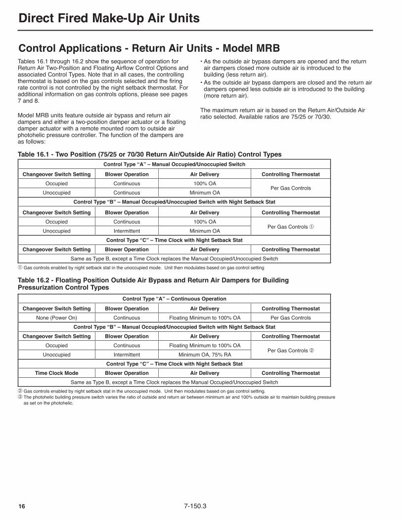
Tables 16.1 through 16.2 show the sequence of operation for Return Air Two-Position and Floating Airflow Control Options and associated Control Types. Note that in all cases, the controlling thermostat is based on the gas controls selected and the firing rate control is not controlled by the night setback thermostat. For additional information on gas controls options, please see pages 7 and 8. Model MRB units feature outside air bypass and return air dampers and either a two-position damper actuator or a floating damper actuator with a remote mounted room to outside air photohelic pressure controller. The function of the dampers are as follows:
Table 16.1 - Two Position (75/25 or 70/30 Return Air/Outside Air Ratio) Control TypesControl Type “A” – Manual Occupied/Unoccupied Switch
Changeover Switch Setting Blower Operation Air Delivery Controlling ThermostatOccupied Continuous 100% OA
Per Gas ControlsUnoccupied Continuous Minimum OA
Control Type “B” – Manual Occupied/Unoccupied Switch with Night Setback Stat
Changeover Switch Setting Blower Operation Air Delivery Controlling ThermostatOccupied Continuous 100% OA
Per Gas Controls ➀Unoccupied Intermittent Minimum OA
Control Type “C” – Time Clock with Night Setback StatChangeover Switch Setting Blower Operation Air Delivery Controlling Thermostat
Same as Type B, except a Time Clock replaces the Manual Occupied/Unoccupied Switch➀ Gas controls enabled by night setback stat in the unoccupied mode. Unit then modulates based on gas control setting
Table 16.2 - Floating Position Outside Air Bypass and Return Air Dampers for Building Pressurization Control Types
Control Type “A” – Continuous Operation
Changeover Switch Setting Blower Operation Air Delivery Controlling ThermostatNone (Power On) Continuous Floating Minimum to 100% OA Per Gas Controls
Control Type “B” – Manual Occupied/Unoccupied Switch with Night Setback StatChangeover Switch Setting Blower Operation Air Delivery Controlling Thermostat
Occupied Continuous Floating Minimum to 100% OAPer Gas Controls ➁
Unoccupied Intermittent Minimum OA, 75% RAControl Type “C” – Time Clock with Night Setback Stat
Time Clock Mode Blower Operation Air Delivery Controlling ThermostatSame as Type B, except a Time Clock replaces the Manual Occupied/Unoccupied Switch
➁ Gas controls enabled by night setback stat in the unoccupied mode. Unit then modulates based on gas control setting.➂ The photohelic building pressure switch varies the ratio of outside and return air between minimum air and 100% outside air to maintain building pressure as set on the photohelic.
Control Applications - Return Air Units - Model MRB• As the outside air bypass dampers are opened and the return
air dampers closed more outside air is introduced to the building (less return air).
• As the outside air bypass dampers are closed and the return air dampers opened less outside air is introduced to the building (more return air).
The maximum return air is based on the Return Air/Outside Air ratio selected. Available ratios are 75/25 or 70/30.

Direct Fired Make-Up Air Units
177-150.3
THIS PAGE WAS INTENTIONALLy LEFT BLANk

Direct Fired Make-Up Air Units
18 7-150.3
Unit SelectionThe next few pages provide an overview of how to select a Direct Fired Make-Up Air Unit, however units are best selected using Modine Breeze™ AccuSpec, an online tool that allows easy, step-by-step selection of Modine HVAC equipment. Please contact your local Modine Sales Representative for a demonstration or access to the system. In order to properly select a direct-fired heating, ventilating, cooling or make-up air unit, it is necessary to have the following basic information.1. Required air handling capacity (CFM).
The air capacity of the unit is usually determined by the ventilation air requirements, exhaust load of the building, infiltration losses, or the air turns/changes of the space.
2. Outdoor and indoor design temperature. The outdoor design temperature is determined by using
the ASHRAE Guide design temperatures for the city where the equipment is to be installed. For heating and ventilating units, the desired room temperature would be used as the indoor design temperature. In the case of 100% make-up air units, the discharge air temperature should be at least equal to the temperature of the air being exhausted.
3. Required heating input capacity (Btu/Hr). The heating input capacity of the unit is determined by
using the formula (for sea level): BTU/hr = CFM x Temp Rise (°F) x 621 / (460 +Discharge Temp)
4. External static pressure to unit. The external static pressure (E.S.P.) is determined using
the ASHRAE Guide for duct losses, or may be provided by the design engineer.
5. Unit configuration with options and accessories (Rainhood, filters, dampers, or evaporative cooler).
The unit configuration is determined by the location where the unit is to be installed. The critical options and accessories are those that add internal static pressure (I.S.P.) to the unit. Once these items are determined, the pressure drop curves would be used to calculate the total pressure drop (T.S.P.)
Total Static Pressure = Internal + External Static Pressure6. Type of fuel and gas pressure. Either natural or propane gas determined by the design
engineer.7. Temperature control method. Either discharge, room or DDC compatible control as
determined by the design engineer.8. Main power supply voltage to unit.9. Altitude at which unit is to be installed.With this information a basic unit can be selected as shown in the following example.Selection Example - 100% Make Up AirSelect an outdoor, slab mounted, direct-fired, 100% make-up air unit, FM insurance option, with vibration isolation to meet the following:1. CFM at sea level = 6,000 cfm2. Outdoor design temp = 10°F, Discharge temp = 70°F3. Heating input capacity = 6000 cfm x (70°F -10°F) x 621 /
(460 + 70) = 421,810 Btu/Hr4. External Static Pressure = 0.74"W.C.5. Right hand controls, airflow is to blow down into building.
The following accessories are to be included: 2" Permanent Filters, Rainhood and Discharge Damper
6. Gas Type = Natural gas, 8-14" W.C. supply pressure.7. 0-10VDC building management control is required.8. Supply Voltage: 460V/60Hz/3Ph. Altitude: 1000 feetWith the information listed above, the basic model, using the Model Nomenclature shown on page 39, can be selected as shown in the following example:
1. Determine the Product Type (Digit 2): The Product Type for 100% make up air is D. Digit 3
represents an internal design sequence and is always B. Digits 1-3 = MDB.
2. Determine the Blower Quantity and Size (Digits 4-6) and Motor HP (Digit 20):
Using Table 6.1, Model Sizes MDB115, 118 and 120 have blower capability to produce 6000 cfm. The blower performance tables can be found on page 22. Since all can provide the required 6000 cfm, the total static pressure for each blower performance curve must be determined. In this example, the selection process will be shown for 115 only (Digits 4-6 = 115).
A) The Pressure Drop of an option or accessory is determined by entering the table at the desired cfm and reading across the table until the cfm intersects the desired item. For this example, in Table 20.1 the 2" Permanent Filter has an approximate 0.17"W.C. pressure drop. This would be repeated for the other accessories. As a result, for MDB115:
• 2" Permanent Filters = 0.17" W.C. • Rainhood without Filters = 0.02" W.C. • Discharge Damper = 0.07" W.C. • Total Internal Static Pressure Drops = 0.26" W.C. The Total Static Pressure for the system is determined
by Internal Static + External Static = Total Static Pressure. For this example 0.26" + 0.74" = 1.00" W.C. T.S.P.
B) Using the total static pressure (T.S.P.) calculated in step 2A, use blower performance table for the Model Size MDB115 in Table 22.1. Enter the table at the required 6000 cfm and follow the cfm line to the right until it intersects with the T.S.P. line of 1.00" W.C. which is shown at the top of the table. At the point of intersection of these two rows and columns, read the required horsepower. For this example the horsepower is 5. Digit 20 = F.
3. Determine the Unit Configuration (Digit 7): Looking at the unit configurations shown on page 39,
configurations C and D both blow down into the building. The specifier wanted right hand controls. The configurations shown on page 39 are facing the controls. For direct fired, the orientation is determined by looking into the inlet of the unit (air blowing at your back). For configuration C, the controls would be on the right hand side. Digit 7 = C.
4. Determine the Cabinet Finish/Location (Digit 8): The unit is specified as being outdoor, so the choices are
either A (unpainted) or C (painted). Unpainted units are constructed of galvanized steel and can outdoors without paint. Since paint was not specified, Digit 8 = A.
5. Determine Maximum Input MBH rating (Digits 9-12): The Heating Input capacity was calculated to be 421,810
Btu/hr (422MBH) based on the CFM and indoor and outdoor design temperatures. The maximum input MBH rating is the maximum rating for the burner size and is not representative of the actual firing rate. In this case, a burner rated 550MBH would be required to satisfy 422MBH. Digits 9-12 = 0550.
6. Determine the Gas Type, Inlet Pressure and Flame Proving (Digit 13): Since not specified, standard flame rod flame proving will be selected. For natural gas, 8-14" W.C. inlet pressure and flame rod flame sensing, Digit 13 = A.
7. Determine the Gas Control System (Digit 14): Reviewing the gas control information on pages 7-8, MDB units can use Maxitrol 14, Maxitrol 44 or Maxitrol SC10 gas controls. The customer the unit to be building management control compatible. The Maxitrol SC10 control is required for this compatibility. Digit 14 = D (0-10VDC signal by others).

Direct Fired Make-Up Air Units
197-150.3
Unit Selection8. Determine the Insurance Requirements (Digit 15): The customer specified FM. Digit 15 = 2 or 3 covers FM less and with restriction respectively. From the information on page 9, if there are inlet blockages such as dampers or filters, FM with restriction must be selected (if FM is required). In the case of this unit, there are filters, so FM with restriction is required. Digit 15=3. Note that if FM was not specified, the standard IRI manifold could have been selected.9. Determine Additional Manifold Options (Digit 16): Since high and low gas switches were not specified, Digit 16 = N.10. Determine the Air Control Option (Digit 17): All 100% make-up air units with single speed motors have Digit 17 = A.11. Determine the Supply Voltage (Digit 18): From item #8 listed above, the 460V/60Hz/3Ph results in Digit 18 = 6.12. Determine Bearings/Vibration Isolation (Digit 19): Since the Bearing Type was not specified and dedicated blower vibration isolation was not specifically called out, the standard spider bearings will be used. Thus, Digit 19 = A. Specify accessory vibration feet for vibration isolation.13. Determine the Motor Horsepower (Digit 20): This was completed in step #2 above. Digit 20 = F.14. Determine the Motor Type (Digit 21): Reviewing Table 25.1, 5HP 460V/60Hz/3ph motors are only available in NEMA Premium Efficiency ODP and
TE. Since the motor type was not specified, NEMA Prem Eff ODP will be used. Digit 21 = 2.
15. Determine the Sheave Arrangement (Digit 22): This digit will be internally assigned by Modine to match the design blower speed.16. Determine the Profile Assembly (Digit 23): This digit will be internally assigned by Modine.Selection Example - Return Air UnitSelect an outdoor, slab mounted, direct-fired, 75/25 return air unit, space pressure control during occupied and maximum return air with night setback during unoccupied, auto changeover from occupied to unoccupied, FM insurance option, with vibration isolation to meet the following:1. CFM at sea level = 6,000 cfm2. Outdoor design temp = 10°F, Return design temp = 60°F (based on night setback temp), Discharge temp = 70°F3. Heating input capacity = 6000 cfm x (70°F -10°F) x 621 ÷ (460 + 70) = 421,810 Btu/Hr Note: Heating capacity is calculated based on 100% outside air mode, not return air mode.4. External Static Pressure = 0.80"W.C.5. Right hand controls, airflow is to blow down into building. The following accessories are to be included: 2" Permanent Filters, Rainhood and Inlet Damper6. Gas Type = Natural gas, 8-14" W.C. supply pressure.7. Discharge temperature control with room override is required.8. Supply Voltage: 460V/60Hz/3Ph9. Altitude: 1000 feet With the information listed above, the basic model, using the Model Nomenclature shown on page 39, can be selected as shown in the following example:1. Determine the Product Type (Digit 2): The Product Type for return air units is R. Digit 3 represents an internal design sequence and is always B. Digits 1-3 = MRB.2. Determine the Blower Quantity and Size (Digits 4-6) and Motor HP (Digit 20):
Using Table 6.1, Model Sizes MRB115, 118 and 120 have blower capability to produce 6000 cfm at 60°F temperature rise and 75/25 RA/OA ratio. The blower performance tables can be found on page 22. Since all can provide the required 6000 cfm, the total static pressure for each blower size must be determined. In this example, the selection process will be shown for 115 only (Digits 4-6 = 115). A) The Pressure Drop of an option or accessory is determined
by entering the table at the desired cfm and reading across the table until the cfm intersects the desired item. For this example, in Table 20.1 the 2" Permanent Filter has an approximate 0.17"W.C. pressure drop. This would be repeated for the other accessories. As a result, for MRB115:
• 2" Permanent Filters = 0.17" W.C. • Rainhood without Filters = 0.02" W.C. • Inlet Damper = 0.01" W.C. • Total Internal Static Pressure Drops = 0.20" W.C. The Total Static Pressure for the system is determined by Internal Static + External Static = Total Static Pressure. For this example 0.20" + 0.80" = 1.00" W.C. T.S.P. B) Same as step 2B in the previous example. Digit 20 = F.3. Determine the Unit Configuration (Digit 7): Same as step 3 in previous example. Digit 7 = C.4. Determine the Cabinet Finish/Location (Digit 8): Same as step 4 in previous example. Digit 8 = A.5. Determine Maximum Input MBH rating (Digits 9-12): Same as step 5 in previous example. Digits 9-12 = 0550.6. Determine the Gas Type, Inlet Pressure and Flame Proving (Digit 13): Same as step 6 in previous example. Digit 13 = A.7. Determine the Gas Control System (Digit 14): Reviewing the Gas Control Selection Table 9.1 on page 9, for discharge control, 75/25 units, outdoor air temperatures above -20°F, Maxitrol 14 controls are an acceptable control up to a maximum discharge air temperature of 90°F (the maximum setting on the TD114). Note that room override is not available on this control system, so an exception must be noted. Digit 14 = A.8. Determine the Insurance Requirements (Digit 15): Same as step 8 in previous example. Digit 15 = 3.9. Determine Additional Manifold Options (Digit 16): Since high and low gas switches were not specified,
Digit 16 = N.10. Determine the Air Control Option (Digit 17): Reviewing the Controls Applications in Table 16.2 on page 16, Control Type C provides the required sequence to meet space pressure control during the occupied period, maximum return air during unoccupied with night setback thermostat and auto changeover between occupied and unoccupied with the timeclock. Digit 17 = H.11. Determine the Supply Voltage (Digit 18): Same as step 11 in previous example. Digit 18 = 6.12. Determine Bearings/Vibration Isolation (Digit 19): As shown on page 10, MRB units come standard with
Pillow Block Bearings. Digit 19=B.13. Determine the Motor Horsepower (Digit 20): This was completed in step #2 above. Digit 20 = F.14. Determine the Motor Type (Digit 21): Same as step 14 in previous example. Digit 21 = 2.15. Determine the Sheave Arrangement (Digit 22): This digit will be internally assigned by Modine to match the design blower speed.16. Determine the Profile Assembly (Digit 23): This digit will be internally assigned by Modine.

20 7-150.3
Direct Fired Make-Up Air Units
Static Pressure Drop DataTable 20.1 - Accessory Static Pressure Drop Data (Inches W.C.)
Model Size CFM
2" P
erm
anen
t V-
Ban
k Fi
lters
2" T
hrow
away
V-
Ban
k Fi
lters
2" F
arr 3
0/30
V-
Ban
k Fi
lters
Inle
t Dam
pers
Inle
t Hoo
d w
ith F
ilter
s
Inle
t Hoo
d w
ithou
t Filt
ers
Evap
Coo
ler
with
Fla
t Ban
k Fi
lters
Evap
Coo
ler
with
Rai
nhoo
d &
Filt
ers
3-W
ay L
ouve
rs
4-W
ay L
ouve
rs
Dis
char
ge
Dam
per
Duc
tless
D
isch
arge
CFM
110
2600 0.15 0.18 0.19 0.01 0.06 0.01 0.04 0.08 0.05 0.05 0.05 0.41 26002800 0.18 0.20 0.22 0.01 0.07 0.02 0.05 0.09 0.06 0.05 0.05 0.47 28003000 0.20 0.22 0.25 0.01 0.08 0.02 0.05 0.10 0.07 0.06 0.06 0.54 30003300 0.24 0.26 0.30 0.01 0.09 0.02 0.06 0.11 0.09 0.08 0.08 0.65 3300
112
2000 0.10 0.11 0.12 0.00 0.04 0.01 0.03 0.05 0.03 0.03 0.03 0.12 20002500 0.14 0.17 0.18 0.01 0.06 0.01 0.04 0.07 0.05 0.04 0.04 0.19 25003000 0.20 0.22 0.25 0.01 0.08 0.02 0.05 0.10 0.07 0.06 0.06 0.27 30003500 0.26 0.29 0.33 0.01 0.10 0.02 0.06 0.12 0.10 0.09 0.09 0.37 35004000 0.34 0.37 0.43 0.02 0.12 0.03 0.08 0.15 0.13 0.11 0.11 0.48 40004500 0.42 0.45 0.54 0.02 0.15 0.04 0.10 0.19 0.16 0.14 0.14 0.61 45004700 0.45 0.49 0.59 0.03 0.16 0.05 0.11 0.20 0.17 0.15 0.15 0.66 4700
115
3000 0.05 0.07 0.06 0.00 0.03 0.00 0.03 0.05 0.02 0.02 0.02 0.14 30003500 0.07 0.08 0.08 0.00 0.04 0.01 0.03 0.06 0.03 0.02 0.02 0.19 35004000 0.08 0.10 0.11 0.01 0.05 0.01 0.04 0.07 0.04 0.03 0.03 0.25 40004500 0.10 0.12 0.13 0.01 0.06 0.01 0.05 0.09 0.04 0.04 0.04 0.31 45005000 0.12 0.15 0.16 0.01 0.07 0.01 0.06 0.11 0.06 0.05 0.05 0.39 50005500 0.15 0.17 0.19 0.01 0.08 0.02 0.06 0.12 0.07 0.06 0.06 0.47 55006000 0.17 0.20 0.23 0.01 0.09 0.02 0.07 0.14 0.08 0.07 0.07 0.56 60006500 0.20 0.22 0.26 0.01 0.10 0.02 0.09 0.16 0.09 0.08 0.08 0.65 6500
118
3500 0.07 0.08 0.08 0.00 0.04 0.01 0.03 0.06 0.03 0.02 0.02 0.09 35004000 0.08 0.10 0.11 0.01 0.05 0.01 0.04 0.07 0.04 0.03 0.03 0.12 40005000 0.12 0.15 0.16 0.01 0.07 0.01 0.06 0.11 0.06 0.05 0.05 0.19 50006000 0.17 0.20 0.23 0.01 0.09 0.02 0.07 0.14 0.08 0.07 0.07 0.27 60007000 0.22 0.25 0.30 0.02 0.11 0.03 0.10 0.19 0.11 0.10 0.10 0.37 70008000 0.28 0.32 0.39 0.02 0.14 0.04 0.13 0.24 0.14 0.12 0.12 0.48 80009000 0.35 0.39 0.49 0.03 0.17 0.04 0.16 0.29 0.18 0.16 0.16 0.61 9000
10000 0.43 0.46 0.60 0.03 0.20 0.06 0.19 0.35 0.22 0.19 0.19 0.76 10000
120
6000 0.05 0.06 0.06 0.00 0.03 0.00 0.04 0.06 0.02 0.02 0.02 0.13 60007000 0.06 0.08 0.08 0.00 0.04 0.01 0.04 0.08 0.03 0.03 0.03 0.17 70008000 0.08 0.09 0.10 0.01 0.05 0.01 0.05 0.10 0.04 0.03 0.03 0.23 80009000 0.09 0.11 0.12 0.01 0.06 0.01 0.06 0.12 0.05 0.04 0.04 0.29 900010000 0.11 0.13 0.15 0.01 0.07 0.01 0.07 0.14 0.06 0.05 0.05 0.35 1000011000 0.13 0.15 0.17 0.01 0.08 0.02 0.09 0.17 0.07 0.06 0.06 0.43 1100012000 0.15 0.17 0.20 0.01 0.09 0.02 0.10 0.19 0.09 0.08 0.08 0.51 1200013000 0.17 0.20 0.24 0.01 0.10 0.02 0.12 0.22 0.10 0.09 0.09 0.60 1300013500 0.18 0.21 0.25 0.02 0.11 0.02 0.13 0.24 0.11 0.10 0.10 0.64 13500
122
8000 0.08 0.09 0.10 0.01 0.05 0.01 0.05 0.10 0.04 0.03 0.03 0.15 80009000 0.09 0.11 0.12 0.01 0.06 0.01 0.06 0.12 0.05 0.04 0.04 0.19 900010000 0.11 0.13 0.15 0.01 0.07 0.01 0.07 0.14 0.06 0.05 0.05 0.24 1000011000 0.13 0.15 0.17 0.01 0.08 0.02 0.09 0.17 0.07 0.06 0.06 0.29 1100012000 0.15 0.17 0.20 0.01 0.09 0.02 0.10 0.19 0.09 0.08 0.08 0.35 1200013000 0.17 0.20 0.24 0.01 0.10 0.02 0.12 0.22 0.10 0.09 0.09 0.41 1300014000 0.19 0.22 0.27 0.02 0.11 0.02 0.14 0.25 0.12 0.10 0.10 0.47 1400015000 0.22 0.25 0.31 0.02 0.13 0.03 0.15 0.29 0.13 0.12 0.12 0.54 1500016000 0.25 0.28 0.35 0.02 0.14 0.03 0.17 0.32 0.15 0.13 0.13 0.61 1600016500 0.26 0.29 0.37 0.02 0.15 0.03 0.18 0.34 0.16 0.14 0.14 0.65 16500
124
10000 0.11 0.13 0.15 0.01 0.07 0.01 0.07 0.14 0.06 0.05 0.05 0.24 1000012000 0.15 0.17 0.20 0.01 0.09 0.02 0.10 0.19 0.09 0.08 0.08 0.35 1200014000 0.19 0.22 0.27 0.02 0.11 0.02 0.14 0.25 0.12 0.10 0.10 0.47 1400016000 0.25 0.28 0.35 0.02 0.14 0.03 0.17 0.32 0.15 0.13 0.13 0.61 1600018000 0.30 0.34 0.44 0.03 0.17 0.04 0.21 0.40 0.19 0.17 0.17 0.78 1800020000 0.37 0.40 0.54 0.03 0.20 0.05 0.24 0.49 0.24 0.21 0.21 0.96 2000021500 0.42 0.46 0.62 0.04 0.22 0.06 0.26 0.56 0.28 0.24 0.24 1.11 21500

217-150.3
Direct Fired Make-Up Air Units
Static Pressure Drop DataTable 21.1 - Accessory Static Pressure Drop Data (Inches W.C.)
Model Size CFM
2" P
erm
anen
t V-
Ban
k Fi
lters
2" T
hrow
away
V-
Ban
k Fi
lters
2" F
arr 3
0/30
V-
Ban
k Fi
lters
Inle
t Dam
pers
Inle
t Hoo
d w
ith F
ilter
s
Inle
t Hoo
d w
ithou
t Filt
ers
Evap
Coo
ler
with
Fla
t Ban
k Fi
lters
Evap
Coo
ler
with
Rai
nhoo
d &
Filt
ers
3-W
ay L
ouve
rs
4-W
ay L
ouve
rs
Dis
char
ge
Dam
per
Duc
tless
D
isch
arge
CFM
127
16000 0.12 0.14 0.16 0.01 0.10 0.01 0.07 0.14 0.05 0.04 0.04 0.25 1600018000 0.14 0.17 0.20 0.02 0.13 0.02 0.09 0.17 0.06 0.06 0.06 0.31 1800020000 0.17 0.20 0.24 0.02 0.15 0.02 0.11 0.21 0.08 0.07 0.07 0.38 2000022000 0.20 0.23 0.29 0.03 0.17 0.03 0.13 0.24 0.09 0.08 0.08 0.46 2200024000 0.23 0.26 0.34 0.03 n/a 0.03 0.15 0.28 0.11 0.10 0.10 0.55 2400026000 0.27 0.30 0.39 0.04 n/a 0.04 0.18 0.33 0.13 0.12 0.12 0.65 26000
130
14000 0.09 0.11 0.12 0.01 0.08 0.01 0.06 0.11 0.04 0.03 0.03 0.14 1400016000 0.12 0.14 0.16 0.01 0.10 0.01 0.07 0.14 0.05 0.04 0.04 0.18 1600018000 0.14 0.17 0.20 0.02 0.13 0.02 0.09 0.17 0.06 0.06 0.06 0.23 1800020000 0.17 0.20 0.24 0.02 0.15 0.02 0.11 0.21 0.08 0.07 0.07 0.29 2000022000 0.20 0.23 0.29 0.03 0.17 0.03 0.13 0.24 0.09 0.08 0.08 0.35 2200024000 0.23 0.26 0.34 0.03 n/a 0.03 0.15 0.28 0.11 0.10 0.10 0.42 2400026000 0.27 0.30 0.39 0.04 n/a 0.04 0.18 0.33 0.13 0.12 0.12 0.49 2600028000 0.30 0.34 0.45 0.05 n/a 0.04 0.21 0.37 0.15 0.13 0.13 0.57 2800030000 0.34 0.38 0.52 0.05 n/a 0.05 0.24 0.42 0.18 0.15 0.15 0.65 30000
220
18000 0.12 0.15 0.17 0.01 0.08 0.01 0.08 0.15 0.05 0.05 0.05 0.29 1800019000 0.13 0.16 0.18 0.01 0.08 0.02 0.09 0.17 0.06 0.05 0.05 0.32 1900020000 0.15 0.17 0.20 0.01 0.09 0.02 0.10 0.18 0.06 0.06 0.06 0.35 2000021000 0.16 0.19 0.22 0.01 0.10 0.02 0.11 0.20 0.07 0.06 0.06 0.39 2100022000 0.17 0.20 0.24 0.01 0.10 0.02 0.11 0.22 0.08 0.07 0.07 0.43 2200023000 0.19 0.21 0.26 0.02 0.11 0.02 0.12 0.23 0.08 0.07 0.07 0.47 2300024000 0.20 0.23 0.28 0.02 0.11 0.02 0.13 0.25 0.09 0.08 0.08 0.51 2400025000 0.21 0.25 0.31 0.02 n/a 0.03 0.15 0.27 0.10 0.09 0.09 0.55 2500026000 0.23 0.26 0.33 0.02 n/a 0.03 0.16 0.29 0.11 0.10 0.10 0.60 2600027000 0.25 0.28 0.35 0.02 n/a 0.03 0.17 0.31 0.12 0.10 0.10 0.64 27000
222
25000 0.21 0.25 0.31 0.02 n/a 0.03 0.15 0.27 0.10 0.09 0.09 0.37 2500026000 0.23 0.26 0.33 0.02 n/a 0.03 0.16 0.29 0.11 0.10 0.10 0.41 2600027000 0.25 0.28 0.35 0.02 n/a 0.03 0.17 0.31 0.12 0.10 0.10 0.44 2700028000 0.26 0.30 0.38 0.02 n/a 0.03 0.18 0.33 0.13 0.11 0.11 0.47 2800029000 0.28 0.31 0.41 0.03 n/a 0.04 0.19 0.35 0.13 0.12 0.12 0.50 2900030000 0.30 0.33 0.43 0.03 n/a 0.04 0.21 0.38 0.14 0.13 0.13 0.54 3000031000 0.31 0.35 0.46 0.03 n/a 0.04 0.22 0.40 0.15 0.14 0.14 0.58 3100032000 0.33 0.37 0.49 0.03 n/a 0.04 0.24 0.42 0.16 0.14 0.14 0.61 3200033000 0.35 0.39 0.52 0.03 n/a 0.05 0.25 0.45 0.17 0.15 0.15 0.65 33000
225
30000 0.14 0.17 0.18 0.01 0.09 0.02 0.07 0.14 0.04 0.04 0.04 0.31 3000032000 0.16 0.19 0.20 0.01 0.10 0.02 0.08 0.16 0.05 0.04 0.04 0.35 3200034000 0.18 0.21 0.23 0.02 0.11 0.02 0.09 0.17 0.06 0.05 0.05 0.40 3400036000 0.20 0.23 0.26 0.02 0.12 0.03 0.10 0.19 0.06 0.06 0.06 0.45 3600038000 0.22 0.25 0.28 0.02 n/a 0.03 0.11 0.21 0.07 0.06 0.06 0.50 3800040000 0.24 0.27 0.31 0.02 n/a 0.03 0.12 0.23 0.08 0.07 0.07 0.55 4000042000 0.26 0.29 0.34 0.02 n/a 0.03 0.13 0.25 0.09 0.08 0.08 0.61 4200044000 0.29 0.32 0.38 0.03 n/a 0.04 0.14 0.27 0.09 0.08 0.08 0.67 4400046000 0.31 0.34 0.41 0.03 n/a 0.04 0.16 0.29 0.10 0.09 0.09 0.73 46000
230
44000 0.29 0.32 0.38 0.03 n/a 0.04 0.14 0.27 0.09 0.08 0.08 0.35 4400046000 0.31 0.34 0.41 0.03 n/a 0.04 0.16 0.29 0.10 0.09 0.09 0.38 4600048000 0.34 0.37 0.44 0.03 n/a 0.04 0.17 0.31 0.11 0.10 0.10 0.42 4800050000 0.36 0.40 0.48 0.03 n/a 0.05 0.18 0.34 0.12 0.11 0.11 0.45 5000052000 0.39 0.43 0.52 0.04 n/a 0.05 0.20 0.36 0.13 0.12 0.12 0.49 5200054000 0.42 0.46 0.56 0.04 n/a 0.06 0.21 0.39 0.14 0.13 0.13 0.53 5400056000 0.45 0.49 0.60 0.04 n/a 0.06 0.23 0.41 0.15 0.14 0.14 0.57 5600058000 0.48 0.52 0.64 0.05 n/a 0.07 0.25 0.44 0.16 0.14 0.14 0.61 5800060000 0.51 0.55 0.68 0.05 n/a 0.07 0.26 0.47 0.18 0.16 0.16 0.65 60000

Direct Fired Make-Up Air Units
22 7-150.3
Blower Performance Data
Model Size CFM
Total Static Pressure (“W.C.)0.25 0.5 0.75 1 1.25 1.5 1.75 2 2.5 3
BHP RPM BHP RPM BHP RPM BHP RPM BHP RPM BHP RPM BHP RPM BHP RPM BHP RPM BHP RPM
110
1600 0.49 882 0.59 998 - - - - - - - - - - - - - - - -1800 0.58 908 0.69 1017 0.82 1119 - - - - - - - - - - - - - -2000 0.69 939 0.83 1042 1.02 1139 1.14 1231 - - - - - - - - - - - -2200 0.86 974 1.04 1071 1.16 1163 1.27 1250 1.38 1334 1.48 1415 - - - - - - - -2400 1.07 1012 1.19 1103 1.30 1190 1.41 1274 1.52 1355 1.66 1432 1.80 1507 1.95 1580 - - - -2600 1.22 1052 1.34 1139 1.45 1222 1.57 1302 1.72 1379 1.86 1453 2.01 1526 2.17 1596 - - - -2800 1.39 1095 1.49 1177 1.64 1256 1.79 1332 1.93 1406 2.09 1478 2.25 1547 2.42 1615 2.76 1746 - -3000 1.57 1140 1.72 1218 1.87 1293 2.02 1366 2.19 1437 2.36 1505 2.53 1573 2.70 1638 - - - -3300 1.95 1210 2.11 1282 2.28 1353 2.45 1421 2.63 1487 2.80 1552 2.98 1615 - - - - - -
112
2000 0.56 717 - - - - - - - - - - - - - - - - - -2500 0.78 751 1.02 843 1.15 927 - - - - - - - - - - - - - -3000 1.15 795 1.30 880 1.43 959 1.57 1033 1.74 1103 - - - - - - - - - -3500 1.46 846 1.64 925 1.82 998 2.00 1068 2.20 1134 2.40 1197 2.60 1258 2.81 1317 - - - -4000 1.92 904 2.13 976 2.34 1044 2.56 1109 2.78 1172 2.99 1232 3.22 1290 3.44 1346 3.89 1452 4.35 15534500 2.51 965 2.74 1032 2.98 1096 3.22 1157 3.46 1216 3.70 1273 3.94 1328 4.18 1381 4.67 1483 - -4700 2.78 991 3.02 1056 3.27 1118 3.52 1177 3.76 1235 4.01 1291 4.26 1345 4.51 1397 4.99 1491 - -
115
3000 0.78 599 1.06 682 - - - - - - - - - - - - - - - -3500 1.07 618 1.25 696 1.42 768 - - - - - - - - - - - - - -4000 1.29 641 1.46 715 1.67 784 1.89 848 2.14 909 - - - - - - - - - -4500 1.53 668 1.76 737 1.99 802 2.24 864 2.50 922 2.77 978 3.05 1031 - - - - - -5000 1.89 697 2.13 763 2.39 825 2.66 883 2.93 939 3.22 993 3.51 1044 3.81 1094 - - - -5500 2.32 729 2.59 791 2.86 850 3.14 906 3.43 959 3.73 1011 4.03 1061 4.34 1109 4.97 1200 - -6000 2.83 762 3.11 821 3.40 877 3.70 931 4.00 982 4.31 1032 4.63 1080 4.95 1126 - - - -6500 3.41 798 3.71 853 4.02 907 4.33 958 4.65 1007 4.97 1055 - - - - - - - -
118
3500 0.99 510 - - - - - - - - - - - - - - - - - -4000 1.16 519 1.37 591 - - - - - - - - - - - - - - - -5000 1.51 543 1.80 610 2.11 671 2.43 728 2.76 782 - - - - - - - - - -6000 2.07 574 2.43 636 2.78 693 3.15 747 3.52 798 3.89 847 4.27 893 4.65 938 - - - -7000 2.82 611 3.22 668 3.62 721 4.03 772 4.44 820 4.85 866 5.27 910 5.71 953 6.59 1034 - -8000 3.76 652 4.20 705 4.64 754 5.09 802 5.56 847 6.03 891 6.50 933 6.98 974 7.94 1051 8.93 11249000 4.89 696 5.39 745 5.89 791 6.40 836 6.91 879 7.43 920 7.94 960 8.46 999 9.51 1073 - -10000 6.30 743 6.85 788 7.40 831 7.95 873 8.50 914 9.06 953 9.62 991 - - - - - -
120
6000 1.53 447 1.89 503 - - - - - - - - - - - - - - - -7000 1.94 466 2.34 519 2.76 568 3.21 614 - - - - - - - - - - - -8000 2.48 489 2.90 538 3.35 585 3.82 628 4.30 670 - - - - - - - - - -9000 3.14 514 3.59 560 4.06 604 4.55 646 5.06 685 5.60 724 6.16 760 6.74 796 - - - -10000 3.93 542 4.41 585 4.90 626 5.43 666 5.97 704 6.54 740 7.13 775 7.72 809 8.97 874 - -11000 4.86 571 5.37 612 5.91 651 6.47 688 7.05 724 7.64 759 8.24 792 8.86 825 10.15 888 11.52 94712000 5.97 602 6.53 640 7.10 677 7.68 712 8.28 747 8.90 780 9.52 812 10.18 843 11.53 904 12.94 96113000 7.27 634 7.85 670 8.45 705 9.06 738 9.69 771 10.34 803 11.01 834 11.69 864 13.09 922 14.55 97713500 7.98 651 8.58 686 9.19 719 9.82 752 10.47 784 11.14 815 11.82 845 12.51 875 13.94 932 - -
122
8000 2.24 426 2.74 478 3.27 528 - - - - - - - - - - - - - -9000 2.75 442 3.28 490 3.83 537 4.41 581 - - - - - - - - - - - -10000 3.36 460 3.91 506 4.49 549 5.09 590 5.74 630 6.41 669 - - - - - - - -11000 4.06 481 4.65 523 5.26 564 5.91 603 6.59 641 7.28 677 8.00 713 - - - - - -12000 4.88 503 5.51 542 6.17 580 6.85 617 7.55 653 8.27 688 9.01 722 9.77 756 11.38 820 - -13000 5.84 526 6.51 563 7.20 599 7.91 634 8.64 668 9.39 701 10.16 734 10.96 766 12.62 827 14.35 88714000 6.95 551 7.65 585 8.37 619 9.11 652 9.87 685 10.66 716 11.47 747 12.30 778 14.01 837 15.79 89415000 8.19 576 8.92 609 9.68 641 10.46 672 11.26 703 12.08 733 12.92 763 13.78 792 15.55 848 17.39 90316000 9.58 602 10.36 633 11.16 663 11.98 693 12.81 723 13.66 751 14.54 780 15.43 807 17.26 862 19.15 91416500 10.35 615 11.15 645 11.96 675 12.80 704 13.65 733 14.52 761 15.41 789 16.31 816 18.18 869 - -
124
10000 2.63 362 3.19 407 3.78 451 4.40 493 - - - - - - - - - - - -12000 3.68 384 4.29 424 4.92 462 5.60 499 6.32 535 7.06 571 - - - - - - - -14000 5.03 413 5.72 447 6.43 481 7.17 514 7.92 547 8.71 579 9.52 610 10.36 640 - - - -16000 6.81 444 7.55 475 8.31 505 9.10 535 9.91 565 10.76 594 11.63 622 12.53 650 14.37 705 16.31 75818000 8.99 478 9.79 506 10.63 534 11.49 561 12.37 587 13.27 614 14.20 640 15.14 665 17.09 716 19.12 76520000 11.67 514 12.55 540 13.45 565 14.37 589 15.31 614 16.27 638 17.26 662 18.26 685 - - - -21500 14.03 542 14.95 566 15.91 589 16.88 613 17.86 635 18.87 658 19.89 681 - - - - - -
➀ Total static pressure should include external static pressure and accessory / option static pressure from Tables 32.1 or 33.1.➁ Brake Horsepower and RPM values are approximate. Please consult the AccuSpec selection software for accurate values.
Table 22.1 - Unit Performance Table ➀ ➁

Direct Fired Make-Up Air Units
237-150.3
Blower Performance Data
Model Size CFM
Total Static Pressure (“W.C.)0.25 0.5 0.75 1 1.25 1.5 1.75 2 2.5 3
BHP RPM BHP RPM BHP RPM BHP RPM BHP RPM BHP RPM BHP RPM BHP RPM BHP RPM BHP RPM
125
10000 2.45 356 3.08 404 - - - - - - - - - - - - - - - -12000 3.30 373 3.97 416 4.67 457 - - - - - - - - - - - - - -14000 4.40 395 5.11 434 5.88 471 6.70 507 7.55 541 8.43 575 - - - - - - - -16000 5.80 420 6.59 455 7.41 489 8.27 522 9.16 554 10.08 585 11.06 615 12.06 645 - - - -18000 7.55 448 8.40 480 9.27 511 10.18 541 11.13 571 12.11 600 13.13 628 14.17 656 16.36 709 - -20000 9.67 478 10.58 507 11.53 536 12.50 564 13.50 591 14.53 618 15.60 645 16.69 670 18.96 721 - -21500 11.55 501 12.51 529 13.49 556 14.51 582 15.56 608 16.63 634 17.73 659 18.86 684 - - - -
127
12000 2.69 315 - - - - - - - - - - - - - - - - - -14000 3.48 327 4.17 366 - - - - - - - - - - - - - - - -16000 4.45 341 5.19 378 5.99 412 - - - - - - - - - - - - - -18000 5.65 358 6.47 392 7.32 424 8.20 455 9.11 485 - - - - - - - - - -20000 7.12 377 7.99 408 8.89 438 9.82 467 10.79 495 11.80 522 12.83 548 - - - - - -22000 8.84 397 9.77 426 10.74 454 11.74 481 12.77 508 13.82 533 14.90 558 16.01 583 - - - -24000 10.87 418 11.87 445 12.90 472 13.96 497 15.04 522 16.15 546 17.28 570 18.44 593 - - - -26000 13.23 441 14.30 466 15.39 491 16.51 515 17.65 538 18.81 561 20.00 584 - - - - - -
130
14000 3.23 292 - - - - - - - - - - - - - - - - - -16000 3.98 300 4.85 338 5.82 374 - - - - - - - - - - - - - -18000 4.88 310 5.81 345 6.83 379 7.90 412 - - - - - - - - - - - -20000 5.99 323 6.98 355 8.02 387 9.12 417 10.29 446 11.52 475 - - - - - - - -22000 7.30 337 8.33 367 9.42 396 10.57 425 11.78 452 13.05 479 14.37 505 - - - - - -24000 8.83 352 9.91 380 11.06 407 12.26 434 13.51 460 14.82 486 16.17 511 17.57 535 - - - -26000 10.60 368 11.75 394 12.95 420 14.20 445 15.50 470 16.84 561 18.23 518 19.67 541 22.69 586 - -28000 12.65 384 13.85 409 15.10 434 16.40 457 17.75 481 19.13 504 20.57 526 22.05 548 - - - -30000 14.96 402 16.23 425 17.54 448 18.88 471 20.28 493 21.72 515 23.20 536 24.72 557 - - - -
220
18000 6.18 516 7.08 562 8.02 606 8.98 648 9.98 688 11.03 726 12.10 763 - - - - - -19000 6.94 530 7.87 574 8.84 617 9.83 657 10.87 696 11.95 734 13.05 770 14.18 805 - - - -20000 7.76 545 8.73 587 9.72 628 10.76 668 11.84 706 12.94 742 14.07 778 15.22 812 - - - -21000 8.66 559 9.66 601 10.70 640 11.77 679 12.87 716 14.00 751 15.16 786 16.35 820 18.80 884 - -22000 9.63 575 10.67 615 11.75 653 12.85 690 13.99 726 15.15 761 16.34 795 17.55 828 - - - -23000 10.69 590 11.77 629 12.88 666 14.02 702 15.18 737 16.38 771 17.60 804 18.84 836 - - - -24000 11.84 606 12.96 644 14.10 680 15.27 715 16.47 749 17.69 782 18.94 814 - - - - - -25000 13.08 622 14.23 659 15.40 694 16.61 728 17.84 761 19.09 794 - - - - - - - -26000 14.41 639 15.59 674 16.80 708 18.04 742 19.30 774 - - - - - - - - - -27000 15.83 656 17.05 690 18.29 723 19.56 755 - - - - - - - - - - - -
222
25000 10.64 518 11.92 556 13.25 593 14.64 628 16.07 663 17.56 697 19.08 729 20.66 761 23.95 823 - -26000 11.64 530 12.95 567 14.32 602 15.74 637 17.20 671 18.71 704 20.27 736 21.87 767 25.20 828 26.93 85727000 12.71 542 14.06 578 15.46 613 16.90 646 18.40 679 19.93 711 21.53 743 23.15 773 26.53 833 28.29 86128000 13.85 555 15.23 589 16.66 623 18.14 656 19.66 688 21.24 719 22.86 750 24.51 780 27.94 838 29.72 86629000 15.06 567 16.48 601 17.95 634 19.45 666 21.02 697 22.62 728 24.26 758 25.94 787 29.43 844 - -30000 16.35 580 17.81 613 19.30 645 20.86 676 22.44 707 24.08 737 25.74 766 27.46 795 - - - -31000 17.72 593 19.21 625 20.75 656 22.33 687 23.95 717 25.61 746 27.31 774 29.05 803 - - - -32000 19.17 606 20.71 637 22.28 668 23.89 698 25.53 727 27.23 755 28.97 783 - - - - - -33000 20.72 620 22.28 650 23.88 680 25.52 709 27.21 737 28.94 765 - - - - - - - -
225
30000 10.05 411 11.57 448 13.17 483 14.84 516 16.59 547 18.42 577 20.32 606 - - - - - -32000 11.54 424 13.12 460 14.77 493 16.50 525 18.29 556 20.17 585 22.11 613 24.12 641 - - - -34000 13.20 438 14.83 472 16.55 504 18.32 535 20.18 565 22.10 594 24.08 621 26.13 648 - - - -36000 15.04 452 16.74 485 18.50 516 20.34 546 22.24 575 24.21 603 26.24 630 28.34 656 32.73 706 - -38000 17.07 466 18.82 498 20.65 528 22.55 557 24.50 586 26.52 613 28.60 639 30.74 664 35.24 713 37.58 73740000 19.29 481 21.12 512 23.00 541 24.95 569 26.96 597 29.04 623 31.17 649 33.38 673 37.97 721 - -42000 21.73 497 23.61 526 25.56 554 27.57 582 29.64 608 31.78 634 33.98 659 36.24 683 - - - -44000 24.37 512 26.32 541 28.34 568 30.40 595 32.55 620 34.75 645 37.01 670 39.32 693 - - - -46000 27.25 528 29.27 555 31.35 582 33.50 608 35.70 633 37.96 657 - - - - - - - -
230
36000 9.71 312 11.56 347 13.50 381 15.53 414 - - - - - - - - - - - -38000 10.78 318 12.68 352 14.67 385 16.76 416 - - - - - - - - - - - -40000 11.94 325 13.90 357 15.95 389 18.09 419 20.32 449 - - - - - - - - - -42000 13.20 332 15.22 363 17.33 393 19.52 423 21.81 451 24.17 479 - - - - - - - -44000 14.56 339 16.64 369 18.81 398 21.07 427 23.40 455 25.81 482 28.30 508 - - - - - -46000 16.03 346 18.17 375 20.40 404 22.72 431 25.10 458 27.57 485 30.11 510 - - - - - -48000 17.62 354 19.82 382 22.12 410 24.48 436 26.92 462 29.50 488 32.05 513 34.74 538 - - - -50000 19.32 362 21.59 389 23.94 416 26.37 442 28.87 467 31.45 492 34.12 516 36.86 540 - - - -52000 21.15 370 23.48 397 25.89 422 28.38 448 30.94 472 33.60 496 36.32 520 39.11 543 44.87 589 - -54000 23.11 379 25.49 404 27.97 429 30.52 454 33.16 478 35.87 501 38.65 524 41.48 547 47.36 591 - -56000 25.18 387 27.65 412 30.18 436 32.81 460 35.51 483 38.28 506 41.11 529 44.00 551 49.98 594 - -58000 27.41 396 29.94 420 32.55 444 35.24 467 38.00 489 40.82 512 43.71 534 46.66 555 - - - -60000 29.77 405 32.38 428 35.06 451 37.82 474 40.63 496 43.51 518 46.46 539 49.46 560 - - - -
➀ Total static pressure should include external static pressure and accessory / option static pressure from Tables 32.1 or 33.1.➁ Brake Horsepower and RPM values are approximate. Please consult the AccuSpec selection software for accurate values.
Table 23.1 - Unit Performance Table ➀ ➁

Direct Fired Make-Up Air Units
24 7-150.3
THIS PAGE WAS INTENTIONALLy LEFT BLANk

Direct Fired Make-Up Air Units
257-150.3
Electrical DataTable 25.1 - Unit Control Circuit Amp Draw
Unit Supply Voltage
115 208 230 460 3.8 2.4 2.2 1.1
Table 25.2 - Motor Data - 1-Phase (60Hz) ➀ ➁
Table 25.3 - Motor Data - 3-Phase (60Hz) ➀ ➁
HP Motor Type Frame Size115V 208V 230V
Efficiency %Amp Draw Amp Draw Amp Draw
3/4ODP 56 11.0 5.5 5.4
➂
TE 56 11.0 5.5 5.4
1ODP 56 13.6 6.8 6.6TE 56 12.0 6.2 6.0
1-1/2ODP 56 15.0 7.8 7.5TE 56 15.0 7.8 7.5
2ODP 145T 20.4 10.2 10.0TE 182T 20.0 10.8 10.0
3ODP 184T 34.0 17.4 17.0TE 184T 32.0 14.8 16.0
5ODP 184T - 23.5 21.0TE 184T - 21.5 19.5
7-1/2ODP 215T - 37.2 35.5TE 215T - 35.0 30.0
➀ Single phase motors, 1-1/2 HP and smaller, feature integral thermal overload protection. Motors 2 HP and larger require external pro-tection. The optional motor starter or variable frequency drive for those sizes provides over-current protection.
➁ Single phase motors are not suitable for use with variable frequency drives.
➂ Motors manufacturers do not rate single-phase motors for efficiency.
HP Motor Type Frame Size208V 230V 460V 575V
Amp Draw Efficiency % Amp Draw Efficiency % Amp Draw Efficiency % Amp Draw Efficiency %
3/4ODP 56 2.8 75.5 3.2 75.5 1.6 75.5 1.1 75.5TE 56 3.0 78.9 3.0 78.9 1.5 78.9 1.3 73.4
1ODP 143T 3.6 82.5 3.4 85.5 1.7 85.5 1.3 85.5TE 143T 3.9 85.5 3.2 85.5 1.6 85.5 1.1 85.5
1-1/2ODP 145T 5.3 84.0 5.6 86.5 2.8 86.5 1.8 86.5TE 145T 5.5 86.5 4.8 86.5 2.4 86.5 1.9 86.5
2ODP 145T 6.7 84.0 5.8 86.5 2.9 86.5 2.4 86.5TE 145T 6.7 86.5 5.7 86.5 2.8 86.5 2.3 86.5
3ODP 182T 9.0 89.5 8.6 89.5 4.3 89.5 3.4 89.5TE 182T 9.1 87.5 8.4 89.5 4.2 89.5 3.2 89.5
5ODP 184T 15.7 87.5 13.6 89.5 6.8 89.5 5.4 89.5TE 184T 14.7 89.5 12.8 89.5 6.4 89.5 5.1 89.5
7-1/2ODP 213T 22.3 91.0 19.8 91.0 9.9 91.0 7.5 91.0TE 213T 20.9 91.7 21.6 91.7 10.8 91.7 8.6 91.7
10ODP 215T 29.0 91.7 25.6 91.7 12.8 91.7 10.0 91.7TE 215T 28.3 89.5 26.8 91.7 13.4 91.7 10.7 91.7
15ODP 254T 43.4 93.0 37.8 93.0 18.9 93.0 15.1 93.0TE 254T 42.0 92.4 38.1 92.4 19.1 92.4 15.8 92.4
20ODP 256T 57.0 93.0 51.0 93.0 25.5 93.0 19.6 93.0TE 256T 56.6 91.0 49.0 93.0 24.5 93.0 20.4 93.0
25ODP 284T 70.0 93.6 61.0 93.6 30.5 93.6 23.8 93.6TE 284T 69.0 93.6 62.0 93.6 31.0 93.6 24.8 93.6
30ODP 286T 82.2 94.1 73.2 94.1 36.6 94.1 28.6 94.1TE 286T 81.0 93.6 73.0 93.6 36.5 93.6 29.7 93.6
40ODP 324T 113.0 93.0 97.0 94.1 48.5 94.1 38 94.1TE 324T 106.0 94.1 94.8 94.1 47.4 94.1 37.8 94.1
50ODP 326T 139.2 94.5 121.0 94.5 60.5 94.5 48 94.5TE 326T 131.0 93.0 120.0 94.5 60.0 94.5 47.9 94.5
Total Unit Amp DrawThe total unit amp draw is a combination of the motor and the control circuit amp draws and can be calculated with the tables shown below.
Unit Control Circuit Amp Draw (Table 37.1) = Motor Amp Draw (Tables 37.2 - 37.3) = Total Unit Amp Draw: =

Direct Fired Make-Up Air Units
26 7-150.3
Component Listing1 Auxiliary Gas Shut-Off Valve2 Combination Main Gas Valve3 High and Low Gas Pressure
Switch4 Main Air Flow Proving Switch5 Main Gas Pressure Regulator6 Main Gas Shut-Off Valve7 Main Gas Valve8 Modulating Valve9 Motorized Main Gas Valve10 N/A11 Orificed Pilot Needle Valve12 Pilot Gas Pressure Regulator13 Pilot Gas Shut-Off Valve14 Pilot Gas Valve15 Plugged Test Port16 Redundant Main Gas Valve
Manifold Arrangements
* Required and field installed when gas pressure exceeds 14" wc (1/2 psi)
* Required and field installed when gas pressure exceeds 14" wc (1/2 psi)
For FM Less Restriction: ➀ Solenoid Valve replaces Motorized Valve➁ Not Required
The manifold arrangements shown are typical and may not match the unit selected. Refer to AccuSpec for actual arrangement.
Table 26.1 - Field Gas Supply Connections
Figure 26.1 - Typical Manifold Component Arrangements Standard, IRI, & FM Arrangement - Up to 400,000 Btu/Hr
Figure 26.3 - Typical Manifold Component Arrangements Standard & IRI Arrangement - Over 720,000 Btu/Hr FM (Less & With Restriction) - Up to 2,500,000 Btu/Hr
Figure 26.4 - Typical Manifold Component Arrangements FM (Less & With Restriction) - Over 2,500,000 BTU/HRNatural Propane
MBH Digit 9-12
8-14” W.C.Digit 13=A
1-5 psigDigit 13=B
11-14” W.C.Digit 13=C
1-5 psigDigit 13=D
275-400 3/4” n/a 3/4” n/a550-720 1” n/a 1” n/a
825 1-1/4” 1” 1” 3/4”1000 1-1/4” 1” 1” 1”1100 1-1/4” 1-1/4” 1-1/4” 1”1375 1-1/2” 1-1/4” 1-1/4” 1”1650 2” 1-1/4” 1-1/2” 1-1/4”
1925-2200 2” 1-1/2” 2” 1-1/4”2475 2-1/2” 1-1/2” 2” 1-1/4”
2750-3575 2-1/2” 2” 2” 1-1/2”3850-4950 n/a 2” n/a 2”5225-7425 n/a 2-1/2” n/a n/a
Figure 26.2 - Typical Manifold Component ArrangementsStandard, IRI, & FM Arrangement - Over 400,000 Btu/h and up to 720,000 Btu/Hr

Direct Fired Make-Up Air Units
277-150.3
Figure 27.1 - Unit and Accessories
Unit and Accessory Weights
Table 27.1 - Unit Weights (all weight in pounds)
Table 27.2 - Accessory Weights (all weight in pounds)
Table 27.3a - Approximate Motor Weights (all weight in pounds)
Table 27.3b - Approximate Motor Weights (all weight in pounds)
Model Size Accessory 110, 112 115, 118 120, 122, 124 125, 127, 130 220, 222 225, 230 Inlet Hood 80 125 165 220 235 385 Inlet Damper 70 95 170 230 260 380 V-Bank Filter Section 100 135 210 280 300 430 Discharge Damper 60 80 95 135 210 285 Discharge Louver 80 95 115 150 225 310 14" Roof Curb 115 140 220 240 285 315 24" Roof Curb 180 215 375 410 485 540 24" High Vertical Unit Inlet Stand 55 70 180 225 - - 48" High Vertical Unit Inlet Stand 75 90 220 265 - -
HP 3/4 1 1-1/2 2 3 5 7-1/2Motor Type ODP TE ODP TE ODP TE ODP TE ODP TE ODP TE ODP TE
Weight 25 25 40 40 40 45 50 50 78 80 90 100 150 145
HP 10 15 20 25 30 40 50Motor Type ODP TE ODP TE ODP TE ODP TE ODP TE ODP TE ODP TE
Weight 220 160 310 240 360 250 425 500 485 525 580 510 710 775
Model Type Digit 7 Digit 19 110 112 115 118 120 122 124 125 127 130 220 222 225 230
MDBA-F
A or B 440 500 800 850 1200 1275 1300 1655 1725 1805 1850 2050 2620 2795C 475 535 850 900 1260 1335 n/a 1730 1800 1880 2100 2300 2895 3070
G-J A or B 480 540 850 900 1350 1425 n/a 1905 1975 2055 n/a n/a n/a n/a
MRB A-FA or B 555 615 885 935 1345 1420 n/a 1880 1950 2030 2070 2270 2925 3100
C 590 650 935 985 1405 1480 n/a 1955 2025 2105 2320 2520 3200 3375
Weight Distribution
A 125 140 220 235 325 345 350 445 465 490 510 570 725 780B 100 120 200 210 300 315 325 400 415 430 395 435 610 645C 90 100 160 170 250 265 270 365 380 395 435 475 560 590D 125 140 220 235 325 345 350 445 465 490 510 570 725 780

Direct Fired Make-Up Air Units
28 7-150.3
FILTERS IN HOOD
(4) 20 x 20 x 2
(6) 20 x 25 x 2
FILTERS IN V-BANk
(4) 20 x 20 x 2
(6) 20 x 25 x 2
SIZE 110 112 115 118
Note: All accessories shipped completely assembled for easy installation. Some accessories shipped separately. All data subject to change. All dimensions subject to manufacturing tolerances.➀ 24" for MDB models, 36" for MRB models.➁ 2 1/4" for MDB models, 14 1/4" for MRB models.➂ 3/4" for MDB models, 1 1/4" for MRB models.
SIZE 110 112 115 118
A 24/36 ① 24/36 ①
36 36
B 43 43 52 52
C 71 71 82 82
D 13 1/4 15 3/4 18 3/4 22
E 11 1/2 13 9/16
16 19
F 9 7/8 8 5/8 11 5/8 10
G 30 30 39 39
H 1 1/8 1 1/8
7/8 7/8
J 1 1/2 1 1/2 1 1
K 3/4 / 11/4➂ 3/4 / 11/4➂
1 1/4 1 1/4
L 21 21
26 1/2 26 1/2
M 20 20
25 1/2 25 1/2
N 38 1/2 38 1/2 54 3/8 54 3/8
P 10101212
Q 26263535
R2 1/4
➁
14 1/4➁
2 1/4
2 1/4
S 6 1/4 7 3/16 8 5/8
10 9/16
Table 28.1 - Filter Quantity / Size (inches)
Table 28.2 - MDB/MRB Unit Dimensions (All dimensions in inches)
Dimensions - MDB/MRB 110-118 Units

Direct Fired Make-Up Air Units
297-150.3
Dimensions - MDB/MRB 120-130 Units
Note: All accessories shipped completely assembled for easy installation. Some accessories shipped separately. All data subject to change. All dimensions subject to manufacturing tolerances.
MATERIAL GAUGES: Unit Casing: 18 gauge galvanized. • Unit Channel Base: (120-130) 12 gauge galvanized. Rain Hood: 18 gauge galvanized. • V-Bank: 14 and 18 gauge galvanized. • Damper Blades: 18 gauge galvanized. Damper Frame: 14 gauge galvanized. • Discharge Louvers: 14 and 18 gauge galvanized.
Table 29.1 - Filter Quantity / Size (inches)
Table 29.2 - MDB / MRB Unit Dimensions (All dimensions in inches)
Model Size
Filter Location
Inlet Hood V-Bank Section
120(9) 20 x 25 x 2 (12) 20 x 25 x 2122
124125
(6) 20 x 25 x 2 (9) 16 x 25 x 2
(10) 20 x 20 x 2 (10) 20 x 25 x 2127
130
Model Size A B C D E F G H J k L M N P Q R S
120 48 78 96 24 7/8 24 7/8 18 9/16 59 1 5/16 1 1/2 1 3/4 31 1/2 31 45 3/8 14 55 2 1/4 11 1/4122 48 78 96 27 3/8 27 3/8 17 5/16 59 1 5/16 1 1/2 1 3/4 31 1/2 31 45 3/8 14 55 2 1/4 12 1/4124 48 78 96 28 3/8 31 3/8 16 13/16 59 1 5/16 1 1/2 1 3/4 31 1/2 31 45 3/8 14 55 2 1/4 13 1/4125 60 92 110 31 3/8 31 3/8 22 5/16 73 1 1/16 1 2 1/4 41 1/2 42 56 20 69 2 1/4 13 1/4127 60 92 110 34 3/8 34 3/8 20 13/16 73 1 1/16 1 2 1/4 41 1/2 42 56 20 69 2 1/4 15 1/4130 60 92 110 36 7/8 36 7/8 19 9/16 73 1 1/16 1 2 1/4 41 1/2 42 56 20 69 2 1/4 16 1/4
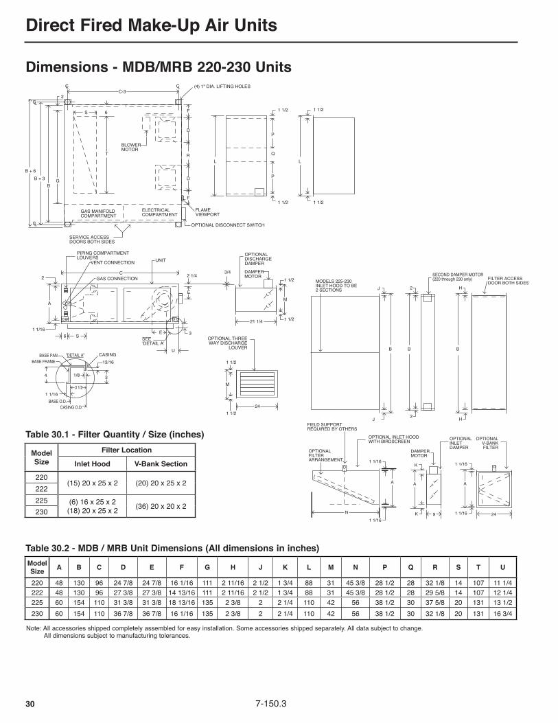
Direct Fired Make-Up Air Units
30 7-150.3
Model Size A B C D E F G H J k L M N P Q R S T U
220 48 130 96 24 7/8 24 7/8 16 1/16 111 2 11/16 2 1/2 1 3/4 88 31 45 3/8 28 1/2 28 32 1/8 14 107 11 1/4222 48 130 96 27 3/8 27 3/8 14 13/16 111 2 11/16 2 1/2 1 3/4 88 31 45 3/8 28 1/2 28 29 5/8 14 107 12 1/4225 60 154 110 31 3/8 31 3/8 18 13/16 135 2 3/8 2 2 1/4 110 42 56 38 1/2 30 37 5/8 20 131 13 1/2230 60 154 110 36 7/8 36 7/8 16 1/16 135 2 3/8 2 2 1/4 110 42 56 38 1/2 30 32 1/8 20 131 16 3/4
Note: All accessories shipped completely assembled for easy installation. Some accessories shipped separately. All data subject to change. All dimensions subject to manufacturing tolerances.
Dimensions - MDB/MRB 220-230 Units
Table 30.1 - Filter Quantity / Size (inches)
Table 30.2 - MDB / MRB Unit Dimensions (All dimensions in inches)
Model Size
Filter Location
Inlet Hood V-Bank Section
220(15) 20 x 25 x 2 (20) 20 x 25 x 2
222225 (6) 16 x 25 x 2
(18) 20 x 25 x 2 (36) 20 x 20 x 2230

Direct Fired Make-Up Air Units
317-150.3
Note: All accessories shipped completely assembled for easy installation. Some accessories shipped separately. All data subject to change. All dimensions subject to manufacturing tolerances.
➀ 24" for MDB models, 36" for MRB models.➁ 3/4" for MDB models, 11/4" for MRB models.
SIZE 110 112 115 118 120 122 125 127 130
L 21 21
26 1/2 26 1/2 31 1/2 31 1/2 41 1/2 41 1/2 41 1/2
M 20 20
25 1/2 25 1/2 31 31 42 42 42
FILTERS IN V-BANk
(4) 20 x 20 x 2
(6) 20 x 25 x 2
(12) 20 x 25 x 2
(10) 20 x 20 x 2 (10) 20 x 25 x 2
P 6 1/4
7 3/16
8 5/8
10 9/16
11 1/4
12 1/4
13 1/4
15 1/4
16 1/4
Q 384747477575898989
T 101012121414202020
S 262635355555696969
SIZE 110 112 115 118 120 122 125 127 130
A 24/36 ① 24/36 ①
36 36 5151636363
B 43 43 52 52 78 78 92 92 92
C 71 71 82 82 96 96 110 110 110
D 13 1/4 15 3/4 18 3/4 22
24 7/8 27 3/8 31 3/8 34 3/8 36 7/8
E 11 1/2 13 9/16
16 19
24 7/8 27 3/8 31 3/8 34 3/8 36 7/8
F 9 7/8 8 5/8 11 5/8 10
18 9/16 17 5/16 22 5/16 20 13/16 19 9/16
G 30 30 39 39 59 59 73 73 73
H 1 1/8 1 1/8
7/8 7/8
1 5/16 1 5/16 1 1/16 1 1/16 1 1/16
K 3/4 / 1 1/4➁
3/4 / 1 1/4➁
1 1/4 1 1/4 1 3/4 1 3/4 2 1/4 2 1/4 2 1/4
R 24/36 ①
24/36 ①
36364848606060
Table 31.1 - Filter Quantity / Size (inches)
Table 31.2 - MDB/MRB Vertical Unit Dimensions (all dimensions in inches)
Dimensions - MDB/MRB 110-130 Units (Vertical Units)

Direct Fired Make-Up Air Units
32 7-150.3
Dimensions - Roof Curb
AIR FLOW
B
JL
D
E
K
F
C
G
A
C
HRETURN
DISCHARGE
DISCHARGE1-3/4
3-1/4
1-3/41-3/4
3-1/4
1-3/41-3/4
1-3/4
14 or 24
14 or 24CURB
BASE FRAME
BASE PAN
GASKET
TYPICAL FOR SINGLE & DUAL FAN
CURB DETAIL
CASING
WOOD NAIL
7/8
1-3/4 1
AIR FLOW
B
JL
D
E
K
F
C
G
A
C
HRETURN
DISCHARGE
DISCHARGE1-3/4
3-1/4
1-3/41-3/4
3-1/4
1-3/41-3/4
1-3/4
14 or 24
14 or 24CURB
BASE FRAME
BASE PAN
GASKET
TYPICAL FOR SINGLE & DUAL FAN
CURB DETAIL
CASING
WOOD NAIL
7/8
1-3/4 1AIR FLOW
B
HK
D
E
J
F
C
A
G
RETURN
DISCHARGE
1-3/4
3-1/4
1-3/41-3/4
3-1/4
1-3/41-3/4
1-3/4
14 or 24
CASINGFLOOR/BASE
GASKET
WOOD NAILER
CURB 2.1
27/321 3/4
14 or 24
CURB DETAIL
TYPICAL FOR SIZE 110-118
Figure 32.1 - Roof-Curb Dimensions - Size 110-130
Figure 32.2 - Roof-Curb Dimensions - Size 220-230
TYPICAL FOR SIZE 110-118 TYPICAL FOR SIZE 120-130
TYPICAL FOR SIZE 220-230
Table 32.1 - Roof-Curb Dimensions - Size 110-130 (inches)
Table 32.2 - Roof-Curb Dimensions - Size 220-230 (inches)
Model Size
Curb Inside Dimensions
Discharge Air Dimensions (optional)
Return Air Dimensions(optional)
Gasket Length (Feet)
Curb Weight (lbs)
A B C D E F G H J k 14" High 24" High110 37 1/2 65 1/2 13 1/4 11 1/2 3 1/2 7 1/8 17 1/8
10 26 8 1/4 19 115 180112 37 1/2 65 1/2 15 3/4 13 9/16 4 7/16 5 7/8 15 7/8115 46 1/2 76 1/2 18 3/4 16 5 7/8 8 7/8 18 7/8
12 35 8 1/4 23 140 215118 46 1/2 76 1/2 22 19 7 13/16 7 1/4 17 1/4120 72 1/2 90 1/2 24 7/8 24 7/8 8 1/2 16 13/16 30 13/16
14 55 14 1/429 220 375122 72 1/2 90 1/2 27 3/8 27 3/8 9 1/2 14 9/16 30 9/16
124 72 1/2 90 1/2 28 3/8 31 3/8 10 1/2 14 1/16 30 1/16 n/a n/a n/a125 86 1/2 104 1/2 31 3/8 31 3/8 10 1/2 19 9/16 35 9/16
20 69 14 1/4 34 240 410127 86 1/2 104 1/2 34 3/8 34 3/8 12 1/2 18 1/16 34 1/16130 86 1/2 104 1/2 36 7/8 36 7/8 13 1/2 16 13/16 32 13/16
Model Size
Curb Inside Dimensions
Discharge Air Dimensions (optional)
Return Air Dimensions(optional)
Gasket Length (Feet)
Curb Weight (lbs)
A B C D E F G H J k L 14" High 24" High220 124 1/2 90 1/2 24 7/8 24 7/8 8 1/2 13 5/16 32 1/8
29 14 107 14 38 285 485222 124 1/2 90 1/2 27 3/8 27 3/8 9 1/2 12 1/16 29 5/8225 148 1/2 104 1/2 31 3/8 31 3/8 10 1/2 16 1/16 37 5/8
32 20 131 14 44 315 540230 148 1/2 104 1/2 36 7/8 36 7/8 14 13 5/16 32 1/8

Direct Fired Make-Up Air Units
337-150.3
THIS PAGE WAS INTENTIONALLy LEFT BLANk

Direct Fired Make-Up Air Units
34 7-150.3
Evaporative Cooling ModuleAll outdoor models can be provided with a field installed evaporative cooling module. When applicable, evaporative cooling is one of the most economical means of supplying conditioned air to a space.Evaporative cooling works on the principle of exchanging sensible heat from the entering warm air to latent heat of vaporization of the cooling water. A special wetting media is placed in the entering air stream of the cooling unit and water is fed down the media. As the air passes through the media, sensible heat from the air is simply transferred to the water in the cooling media, causing the water to evaporate. Because the sensible heat from the air is simply transferred to the water, and both the water vapor and cooled air remain in the system, there is no net energy change in the system. However, the dry bulb temperature of the air has been lowered and provides cooling for the space.The temperature of the cooling air will be dependent on three criteria. These criteria are: 1. The design dry bulb temperature 2. The design wet bulb temperature 3. The percent effectiveness of the cooling mediaThe design dry and wet bulb temperatures can be obtained from the climactic table of the ASHRAE fundamentals. The percent effectiveness of the cooling media is determined from the media performance curve shown in Curve 70.1 for the 12" media based on the velocity across the media. The velocity can be determined by dividing the desired cfm of the unit by the face area of the cooling media for the unit. The media face areas are shown in the Evaporative Cooler Dimensional, Performance, and Weight Data Table 38.1. All evaporative coolers are designed with face velocities below the point of water carryover, thus eliminating the need for moisture elimination pads. For media pressure drops, refer to the evaporative cooling pressure drops included with the unit blower performance curves.Evaporative coolers are available with 2 types of media: 1. Munters CELdek® Celluose 12" media providing brand
name media performance. 2. Munters GLASdek® Fiberglass 12" media which is a
fiberglass media material for applications requiring UL 900, Class 2 fire rating and complies with NFPA codes. .
Standard Features• 12" Munters CELdek® evaporative cooling media• 304 stainless steel water reservoir and casing• 2" permanent aluminum mesh washable pre-filters• Internal thermal overload protected 115V/1phmotor• Front access to pump motor, media, and water connections• Float switch - Prevents the pump motor from operating if the water level in the reservoir is below the switch.• Float valve and bleed line• Adjustable leveling screws• Water inlet, drain, overflow connections (1/2" NPT)
Optional Features - Factory Installed• 12" Munters 12" GLASdek® media• 1" polyester cleanable pre-filter• Rainhood with 2" permanent aluminum mesh washable pre-filters
Accessories - Field Installed• Manual remote operated fill and drain kit ➀• Manual remote operated fill and drain kit with freeze protection ➀• Automatic remote operated fill and drain kit ➀• Automatic remote operated fill and drain kit with freeze protection ➀➀ Valves rated for 50 psi maximum water pressure.
Evaporative Cooling Performance ExampleDetermine the final dry bulb temperature for a model size 130 with a rated air capacity of 30,000 cfm with 12'' GLASdek media. The unit is to be installed in Phoenix, Arizona. The ASHRAE guide shows a design dry bulb temperature of 109°F and a design wet bulb temperature of 71°F. Also determine the apparent cooling capacity of the evaporative cooler.1. Determine the face velocity across the media located in Table
8.1. Find the model size of the selected unit and then find the corresponding media face area (For the model size 130, the media face area is 54 ft2 of media. To calculate the face velocity:
FPM = CFM / Media Face Areaor 30,000 CFM / 54 ft2 = 556 FPM
2. Determine the media percent effectiveness. Enter Figure 7.1 at 556 FPM and follow up the graph until the FPM line intersects with the 12'' media % curve. At the point of intersection, read across to the left and find the percent effectiveness. For this example, the effectiveness is 88%.
3. Determine final dry bulb air temperature of conditioned air.LAT = EAT DB – (% Eff. x (EAT DB – EAT WB))
LAT = 109°F – (0.88 x (109°F – 71°F)) = 76°F DB Once the final dry bulb temperature has been determined, the
point of operation can be plotted on the psychrometric chart. The LAT dry bulb is 76°F and the wet bulb remains constant so it is 71°F.
4. Determine the cooling capacity of the unit. The cooling capacity of the unit is defined as the apparent cooling capacity because it is dependent on a specific set of temperature conditions. As these conditions change, so will the apparent cooling capacity.
Q = 1.08 x (EAT DB – LAT DB) x CFMQ = 1.08 x (109°F – 76°F) x 30,000 CFM = 1,069,200 Btu/Hr
Figure 34.1 - Evaporative Cooling Effectiveness Curve
Definition of TermsEAT = Entering Air TemperatureLAT = Leaving Air TemperatureDB = Dry BulbWB = Wet Bulb% Eff. = Percent EffectivenessQ = Apparent Cooling Capacity
Evaporative Cooling
200 300 400 500 600 700
100%
90%
80%
AIR VELOCITY(FEET PER MINUTE)
EV
AP
OR
ATIV
E C
OO
LIN
G(%
EF
FE
CT
IVE
NE
SS
)
12'' MEDIA %
800100

Direct Fired Make-Up Air Units
357-150.3
Evaporative CoolingFigure 35.1 - Evaporative Cooling Module
Table 35.1 - Evaporative Cooling Specifications
Model Size
Evaporative Cooler 2" Pre-Filters 12" Evaporative Media 2" Dist. Pad Weight (Lbs.)
A B C DCFM Range
Qty Size (L x H)
Face Area (sq ft)
Max. Vel.
(FPM)Qty Size
(W x H)Face Area (sq ft)
Max Vel.
(FPM)Qty Size
(W x H) Ship Oper HoodMin Max
110 48 47 39 17 1,600 3,300 6 16 x 20 13.33 248 4 12 x 36 12.00 275 1 12 x 48 265 525 62112 48 47 39 17 2,000 4,700 6 16 x 20 13.33 353 4 12 x 36 12.00 392 1 12 x 48 265 525 62115 60 59 48 29 3,000 6,500 6 20 x 25 20.83 312 5 12 x 36 15.00 433 1 12 x 48 395 720 75118 60 59 48 29 3,500 10,000 6 20 x 25 20.83 480 5 12 x 48 20.00 500 1 12 x 48 395 720 75
120 84 71 74 41 6,000 13,5003 20 x 20
35.00 386 7 12 x 60 35.00 3861 12 x 60
610 1065 10512 16 x 20 1 12 x 24
122 84 71 74 41 8,000 16,5003 20 x 20
35.00 471 7 12 x 60 35.00 4711 12 x 60
610 1065 10512 16 x 20 1 12 x 24
124 84 71 74 41 10,000 21,5003 20 x 20
35.00 614 7 12 x 60 35.00 6141 12 x 60
610 1065 10512 16 x 20 1 12 x 24
125 108 71 88 53 10,000 21,5009 20 x 20
45.00 478 9 12 x 60 45.00 4781 12 x 48
755 1340 1109 16 x 20 1 12 x 60
127 108 83 88 53 12,000 26,0009 20 x 25
56.25 462 9 12 x 72 54.00 4811 12 x 48
835 1420 1259 16 x 25 1 12 x 60
130 108 83 88 53 14,000 30,0009 20 x 25
56.25 533 9 12 x 72 54.00 5561 12 x 48
835 1420 1259 16 x 25 1 12 x 60
220 144 71 126 41 18,000 27,00012 16 x 20
60.00 450 12 12 x 60 60.00 450 2 12 x 72 1065 1845 14012 20 x 20
222 144 71 126 41 25,000 33,00012 16 x 20
60.00 550 12 12 x 60 60.00 550 2 12 x 72 1065 1845 14012 20 x 20
225 180 95 150 53 30,000 46,0009 20 x 25
106.25 43315 12 x 72
105.00 438 3 12 x 60 1735 2710 17527 20 x 20 15 12 x 12
230 180 95 150 53 36,000 60,0009 20 x 25
106.25 56515 12 x 72
105.00 571 3 12 x 60 1735 2710 17527 20 x 20 15 12 x 12

Direct Fired Make-Up Air Units
36 7-150.3
A. SpecificationsGeneralContractor is to install units according to manufacturers published installation instructions, ANSI Z223.1 (also known as NFPA 54 National Fuel Gas Code), and in accordance with all local codes. After installation, installer is to perform a complete start-up check as required by the manufacturer. A copy of the start-up report shall be left with the owner.
B. StandardsB.1 The unit(s) shall include ETL design certification for use in:
______ the U.S. and Canada to ANSI Z83.4 - latest revision, standard for “Non-Recirculating Direct Gas-Fired Industrial Air Heaters” for safe operation, construction, and performance (Model MDB only).
______ the U.S. only toANSI Z83.18 - latest revision, standard for “Recirculating Direct Gas-Fired Industrial Air Heaters” for safe operation, construction, and performance (Model MRB only).
C. Mechanical ConfigurationC.1. The unit(s) shall have right side gas and electrical controls access (left
hand access optional) as viewed when looking into the inlet of the unit. Blower/motor compartment access will be on the opposite side as viewed when looking into the inlet of the unit.
C.2. The unit(s) shall be provided with a 14” high (24” high optional), prefabricated 14 gauge, unpainted G90 Galvanized steel roof curb with assembly hardware for field assembly (Unit sizes 110-118 only).
C.2. The unit(s) shall be provided with a 14” high (24” high optional), prefabricated 12 gauge, unpainted G90 Galvanized steel roof curb with assembly hardware for field assembly (Unit sizes 120-130 and 220-230 only).
C.4.a. The unit(s) shall be provided with four (4) rubber-in-shear double deflection vibration isolation feet with support mounting for unit.
C.4.b. The unit(s) shall be provided with two (2) rubber-in-shear double deflection vibration isolation feet with support mounting for V-Bank filter section.
C.4.c. The unit(s) shall be provided with four (4) rubber-in-shear double deflection vibration isolation hangers with support mounting for unit.
C.4.d. The unit(s) shall be provided with two (2) rubber-in-shear double deflection vibration isolation hangers with support mounting for V-Bank filter section.
D. Unit CasingD.1. The unit(s) casing shall be constructed from minimum 18 gauge steel
and designed for:_____Outdoor installation, with unpainted G90 Galvanized steel._____Indoor installation, with unpainted G90 Galvanized steel._____ Outdoor installation, with painted Galvannealed steel with gray-
green, air-dry industrial enamel or prepainted G90 Galvanized steel.
_____ Indoor installation, with painted Galvannealed steel with gray-green, air-dry industrial enamel or prepainted G90 Galvanized steel.
D.2. The unit(s) casing roof shall be designed with a rain drip edge to prevent water entry.
D.3. The unit(s) base shall be constructed of minimum 14 gauge galvanized steel and shall be designed for rail, slab, or roof curb mounting.
D.4. The burner section shall be insulated with 1 inch, 1-1/2 lb density acoustical and thermal insulation. The insulation shall be made of glass fibers bonded with a thermosetting resin and overlaid with a fire-resistant black acrylic coating for additional strength. The acrylic coating must meet the requirements of ASTM C 665 for fungi resistance.
D.5. The unit(s) shall include four hinged service access doors (two on each side). Each door shall have a minimum of two tooled access draw tight fasteners. Gas piping and electrical controls shall be mounted in separate enclosures, isolated from the each other and the air stream and shall have independent service access doors. The blower motor and drives shall be accessible through an access service door.
D.6. Each unit shall include a minimum of four factory installed lifting lugs for handling and installation. Each lug will include a 1” diameter hole for lifting hooks.
E. Inlet/Discharge Options and/or Accessories:E.1. The unit(s) shall include a field installed V-Bank filter section (factory
installed on horizontal, 110 through 124 size units) with:_____2” permanent aluminum filters._____2” FARR® Aeropleat 3 pleated throwaway filters._____2” FARR® 30/30 pleated throwaway filters.
E.2. The V-Bank filter section shall be constructed from minimum 18 gauge:_____Un-painted G90 Galvanized steel._____ Painted Galvannealed steel with gray-green, air-dry industrial
enamel or prepainted G90 Galvanized steel.
The V-Bank section will be fully assembled. The maximum air velocity through the filters shall not exceed 520 fpm.
E.3. The V-Bank filter section shall be insulated with 1 inch, 1-1/2 lb density acoustical and thermal insulation. The insulation shall be made of glass fibers bonded with a thermosetting resin and overlaid with a fire-resistant black acrylic coating for additional strength. The acrylic coating must meet the requirements of ASTM C 665 for fungi resistance.
E.4. The unit(s) shall include an optional field installed motorized 2-position inlet damper (factory installed on horizontal, 110 through 124 size units).
E.5. Inlet damper frame shall be constructed from minimum 14 gauge steel and blades shall be a minimum of 18 gauge steel. Material shall be:_____Un-painted G90 Galvanized steel._____ Painted Galvannealed steel with gray-green, air-dry industrial
enamel or prepainted G90 Galvanized steel.
E.6. The unit(s) shall include an optional field installed inlet Rain Hood with Bird Screen without filters (with 2” permanent filters optional) (factory installed on horizontal, 110 through 124 size units). The maximum inlet air velocity shall not exceed 720 fpm (520 fpm with optional filters).
E.7. Inlet Rain Hood with Bird Screen shall be fully assembled and constructed of minimum 18 gauge:_____Un-painted G90 Galvanized steel._____ Painted Galvannealed steel with gray-green, air-dry industrial
enamel or prepainted G90 Galvanized steel.
E.8. The unit(s) shall include inlet Rain Hood/V-Bank support legs.
E.9. The unit(s) shall include a field installed motorized 2-position discharge damper.
E.10. Discharge damper frame shall be constructed from minimum 14 gauge steel and damper blades shall be a minimum of 18 gauge steel. Material shall be:_____Un-painted G90 Galvanized steel._____ Painted Galvannealed steel with gray-green, air-dry industrial
enamel or prepainted G90 Galvanized steel.
E.11. The unit(s) shall include field installed discharge louvers. Each louver shall have field horizontally adjustable air deflection blades. Direction of airflow shall be:_____3-Way_____4-Way
E.12. Discharge louver shall be constructed from minimum 18 gauge:_____Un-painted G90 Galvanized steel._____ Painted Galvannealed steel with gray-green, air-dry industrial
enamel or prepainted G90 Galvanized steel.
E.13. The unit(s) shall include 24” high (48” high) field installed, factory assembled vertical inlet stand without inlet screen (with inlet screen optional). Inlet stand shall be constructed from minimum 18 gauge painted Galvannealed steel. Paint shall be gray-green, air-dry industrial enamel.
Specifications

Direct Fired Make-Up Air Units
377-150.3
F. Blower SectionF.1.a. The unit(s) shall include one _____” diameter, forward curved, double
width, double inlet (DWDI) belt driven blower, to supply ______ cfm against a total static pressure of _____” W.C. using a _____ hp motor. The minimum blower to internal side wall clearance (including insulation if applicable) shall not be less than one half of the blower wheel diameter.
F.1.b. The unit(s) shall include two _____” diameter, forward curved, double width, double inlet (DWDI) belt driven blowers, to supply ______ cfm against a total static pressure of _____” W.C. using a _____ hp motor. The minimum blower to internal side wall clearance (including insulation if applicable) shall not be less than one half of the blower wheel diameter, and the distance between the blowers shall be not less than one blower diameter.
F.2. The total static pressure shall include allowances for a minimum pressure drop of _____” W.C. for field connected ductwork, and _____” W.C. for factory/field installed options/accessories.
F.3. The blower bearings shall be:_____Permanently lubricated spider ball bearings._____Greaseable, heavy duty pillow block ball bearings.
F.4. The unit(s) shall include extended blower bearing grease lines with externally mounted grease fittings on the exterior of the unit casing.
F.5. The blower and motor assembly shall be fully spring isolated with flexible duct connection to unit casing to allow for vibration isolation.
F.6. The blower section shall be insulated with 1 inch, 1-1/2 lb density acoust-cal and thermal insulation. The insulation shall be made of glass fibers bonded with a thermosetting resin and overlaid with a fire-resistant black acrylic coating for additional strength. The acrylic coating must meet the requirements of ASTM C 665 for fungi resistance.
F.7. The blower motor horsepower shall be _____
F.8. The blower motor shall be rated for:_____115V/60Hz/1Ph_____208V/60Hz/1Ph_____230V/60Hz/1Ph_____208V/60Hz/3Ph_____230V/60Hz/3Ph_____460V/60Hz/3Ph _____575V/60Hz/3Ph
F.9. The blower motor type shall be:_____Single-speed, open drip proof (ODP)._____Single-speed, open drip proof, NEMA Premium efficiency (ODP HE)._____Single-speed, totally enclosed (TE)._____Single-speed, totally enclosed, NEMA Premium efficiency (TE HE).
F.10. The motor wiring shall be in metal conduit.
F.11. The unit(s) shall be provided with an adjustable motor sheave and fixed blower sheave to allow for minor adjustment of the blower RPM at the jobsite.
F.12. The unit(s) shall be provided with:_____A factory installed and wired motor starter._____A field installed variable frequency drive for blower motor control.
G. Gas Controls/Manifold AssemblyG.1. The unit(s) gas controls shall be designed for use with:
_____Natural gas with an inlet gas pressure of 8-14” W.C._____Natural gas with an inlet gas pressure of 1-5 psig._____Propane gas with an inlet gas pressure of 11-14” W.C._____Propane gas with an inlet gas pressure of 1-5 psig.
G.2. The gas controls and manifold assembly shall meet insurance requirements of:_____Industrial Risk Insurers (IRI)._____Factory Mutual (FM) Less Restriction._____Factory Mutual (FM) With Restriction.
G.3.a. The standard gas controls and manifold assembly shall include, at a minimum, a main gas hand shut-off valve, auxiliary hand shut-off valve, pilot gas hand shut-off valve, main gas regulator, pilot gas regulator, main gas solenoid valve, redundant main gas solenoid valve, pilot gas sole-noid valve, modulating gas valve, and three gas pressure test ports. See “Ignition and Safety Controls” for additional optional components” (non-FM units and FM units up to 2500MBH).
G.3.b. The standard gas controls and manifold assembly shall include, at a minimum, a main gas hand shut-off valve, two auxiliary hand shut-off valves, pilot gas hand shut-off valve, main gas regulator, pilot gas regulator, main gas motorized valve, redundant main gas motorized valve, pilot gas solenoid valve, modulating gas valve, four gas pressure test ports and combination high and low gas pressure switches (FM with restriction above 2500).
G.3.c. The standard gas controls and manifold assembly shall include, at a minimum, a main gas hand shut-off valve, auxiliary hand shut-off valve, pilot gas hand shut-off valve, main gas regulator, pilot gas regulator, main gas motorized valve, redundant main gas solenoid valve, pilot gas solenoid valve, modulating gas valve, four gas pressure test ports and combination high and low gas pressure switches (FM less restriction above 2500).
H. Ignition and Safety ControlsH.1. The unit(s) shall be supplied with intermittent pilot ignition with 100%
lockout on flame failure with a manual reset. These controls shall include, at a minimum, a flame safeguard ignition control, spark pilot ignition generator, manual reset high temperature limit control, primary and secondary electrical circuit fuses, low air flow proving switch, high air flow cutoff switch and a safety pre-purge timed delay relay.
H.2. The pilot flame supervision method shall be:_____Flame rod._____ Flame rod and shall also include main flame sensing via a
secondary flame rod (1925MBH and above)
H.3. The unit(s) shall include a combination high and low gas pressure switch to prevent the unit from firing if the gas pressure is below the minimum gas pressure or above the maximum gas pressure. The switch is a manual reset type.
I. Temperature ControlsI.1.a. The unit(s) shall be provided with a Maxitrol System 14 Electronic
Modulation Discharge Air Temperature control system. This system shall include a remote temperature dial for adjusting the set point of the discharge air temperature sensor. The discharge air sensor shall monitor the discharge air temperature and modulate the firing rate of the main burner to maintain the desired discharge air temperature. The temperature range of the remote temperature dial shall be 55-90°F.
I.1.b. The unit(s) shall be provided with a room temperature override thermostat to override the discharge air temperature setting by 15°F.
I.1.c. The unit(s) shall be provided with a Maxitrol System 44 Electronic Modulation Room Air Temperature control system. This system shall include a modulating room thermostat to regulate the firing rate of the main burner based on space temperature thermostat demand. The temperature set point range of the room thermostat shall be 55-90°F. This system also includes a discharge air sensor to provide high and low discharge air temperature limits. The discharge air sensor will prevent make-up air from being delivered to the space at temperatures which are below its set point, even if the room thermostat is satisfied, and will prevent the room thermostat from over-firing the burner when mild out-door temperatures exist and the maximum firing capacity of the burner is not required to achieve the desired winter design discharge air temperature.
I.1.d. The unit(s) shall be provided with a Maxitrol Electronic Modulation SC10 Signal Conditioner to provide DCC compatible controls. This system shall include a signal conditioner that utilizes an external 0-10Vdc or 4-20 mA control signal (by others) to control the discharge air temperature. The control signal to the electronic modulating gas valve is controlled by a discharged air sensor (by others) that is compatible with the building management system. An increase or decrease in input signal modulates the main burner gas flow to maintain the desired discharged air temperature. Also included with this system is a discharge air sensor which is used as a high temperature limit control. The discharge air sensor will prevent make-up air from being delivered above the unit discharge operating limit (set for 105°F).
Specifications

Direct Fired Make-Up Air Units
38 7-150.3
I.2.a. The unit(s) shall be supplied with a remote control panel having main valve and alarm lights, a Summer/Off/Winter Switch and a general purpose NEMA 1 enclosure.
The remote panel shall be compatible with the temperature controls and unit configuration.
I.2.b. The remote panel shall include:_____No additional lights_____ An optional blower on light and a clogged filter light. A clogged filter
switch will be mounted on the unit.
J. ElectricalJ.1. The unit(s) shall be completely factory wired to provide for single point
wiring for the main power supply to the unit. The main control panel shall include a numbered terminal strip for all factory wiring and field wiring connections. Units which must be split shipped because of their physical size shall have electrical wire connections tagged and numbered for ease of reconnection during installation.
J.2. The supply voltage to the unit shall be:_____115V/60Hz/1Ph_____208V/60Hz/1Ph_____230V/60Hz/1Ph_____208V/60Hz/3Ph_____230V/60Hz/3Ph_____460V/60Hz/3Ph _____575V/60Hz/3Ph
J.3. The unit(s) shall be provided with a factory mounted and wired control transformer to reduce the supply voltage to 115V/60Hz/1Ph.
J.4. The unit(s) shall be provided with:_____115V main controls and 24V Maxitrol temperature controls._____24V main controls and 24V Maxitrol temperature controls.
Included is a factory mounted and wired control transformer to reduce the main control voltage from 115V to 24V.
J.5. The unit(s) shall be provided with:_____A field mounted fusible general purpose disconnect switch._____ An indoor/outdoor factory mounted dead front main non-fusible
disconnect switch.
k. Optional Factory Installed ControlsK.1. The unit(s) shall be provided with factory installed timed freeze protection
discharge air thermostat used to prevent building freeze up in the event of a burner ignition failure. The timer is typically set for 180 seconds.
K.2. The unit(s) shall be provided with factory installed mild temperature inlet on/off duct stat to automatically lockout the gas controls when the outdoor air temperature reaches the desired set point.
K.3. The unit(s) shall be provided with an exhaust fan interlock contact to initiate a customer exhaust fan starter circuit. The interlock is an auxiliary motor starter contact that closes when the main motor starter contacts close.
K.4. The unit(s) shall be provided with an exhaust fan interlock relay to initiate a customer exhaust fan starter circuit. The exhaust fan interlock relay contacts close when main airflow is proven.
K.5. The unit(s) shall be provided with a 10 point circuit analyzer (12 point analyzers optional) that steps through the unit sequence of operation to provide unit operation status for service personnel.
K.6. The unit(s) shall be provided with service door electrical interlock switch that breaks power in the control circuit if the door is opened. The switch can be overridden for servicing.
K.7. The unit(s) shall be provided with a convenience outlet with a 115V GFCI service receptacle mounted in the electrical controls section. Outlet requires separate 115V power supply by others.
L. Accessory Field Installed ControlsL.1. The unit(s) shall be provided with a manual reset duct mounted fire
stat to disable power to the unit if the temperature sensed by the stat exceeds the desired setting.
L.2. The unit(s) shall be provided with:_____ A 7-Day mechanical time clock to operate the unit on user
programmed time intervals._____ A 7-Day electronic programmable time clock to operate the unit on
user programmed time intervals.
L.3. The unit(s) shall be provided with a night setback thermostat. The night setback thermostat only enables the unit in the unoccupied mode. The standard unit temperature controls control firing rate.
Specifications

Direct Fired Make-Up Air Units
397-150.3
1,2 - Product Type (PT)MD - 100% Make Up AirMR - Return Air
3 - Design Sequence (DS)B - Internally Assigned
4 - Blower Quantity (BQ)1 - Single Blower Unit2 - Twin Blower Unit
5,6 - Blower Size (in.) (BS)10 - 10" 20 - 20"12 - 12" 22 - 22"15 - 15" 24 - 25" x 22" (single blower only)18 - 18" 25 - 25"20 - 20" 27 - 27" 30 - 30"
7 - Unit Configuration (UC)A - Horizontal, right access, straight discharge (bottom return on MR)B - Horizontal, left access, straight discharge (bottom return on MR)C - Horizontal, right access, bottom discharge (bottom return on MR)D - Horizontal, left access, bottom discharge (bottom return on MR)E - Horizontal, right access, top discharge (not available on MR)F - Horizontal, left access, top discharge (not available on MR)G - Vertical, right access, top discharge (not available on MR)J - Vertical, right access, top-right discharge (not available on MR)
8 - Cabinet Finish and Location of Installation (CF)A - Unpainted, Outdoor InstallationB - Unpainted, Indoor InstallationC - Painted, Outdoor InstallationD - Painted, Indoor Installation
9, 10, 11, 12 - Maximum Burner Input (MBH) (MBTU)0275 38500550 41250825 44001000 46751100 49501375 52251650 55001925 57752200 60502475 63252750 66003025 68753300 71503575 7425 0400 - Example: If burner rating is 389MBH, 0400 will be used in model number
13 - Gas Type and Inlet Pressure (GT)A - Natural Gas (8-14") B - Natural Gas (1-5 psi) C - Propane Gas (11-14") D - Propane Gas (1-5 psi)
14 - Gas Control System (GC)A - Maxitrol 14B - Maxitrol 44C - SC10 DDC (4-20 mA)D - SC10 DDC (0-10 VDC)
15 - Insurance (I)1 - IRI (standard ETL)2 - FM less Restriction3 - FM with Restriction
16 - Additional Manifold Options (MO)C - High & Low Gas Pressure SwitchN - None
17 - Air Control Option (AC)A - 100% MUA - Single SpeedB - 100% MUA - Two Speed (VFD) - Type AC - 100% MUA - Two Speed (VFD) - Type BD - 100% MUA - DDC Control (VFD) - Type AE - 100% MUA - DDC Control (VFD) - Type BF - Space Pressure Control (MD with VFD or MR) - Type AG - Space Pressure Control (MD with VFD or MR) - Type BH - Space Pressure Control (MD with VFD or MR) - Type CI - Return Air - Fixed 75/25 Dampers - Type AJ - Return Air - Fixed 75/25 Dampers - Type BK - Return Air - Fixed 75/25 Dampers - Type CL - Return Air - Fixed 70/30 Dampers - Type AM - Return Air - Fixed 70/30 Dampers - Type BN - Return Air - Fixed 70/30 Dampers - Type C
18 - Supply Voltage (SV)1 - 115/60/1 4 - 208/60/32 - 208/60/1 5 - 230/60/33 - 230/60/1 6 - 460/60/3
19 - Bearings and Vibration Isolation (BT)A - Spider Bearings - No Vibration IsolationB - Pillow Block Bearings - No Vibration IsolationC - Pillow Block Bearings - With Spring Vibration Isolation
20 - Motor HP (HP)A - 3/4 H - 10B - 1 I - 15C - 1.5 J - 20D - 2 K - 25E - 3 L - 30F - 5 M - 40G - 7.5 N - 50
21 - Motor Type (MT)1 - ODP2 - ODP - High Efficiency5 - TE6 - TE - High Efficiency
22 - Sheave Arrangement (SA)A - (see Sheave Tables)
23 - Profile Assembly (PA)A - (Internally assigned)
Figure 39.1 - Unit Configurations ➀
2
A = HRS
2
B = HLS
2
C = HRB
2
D = HLB
F = HLT
5
A = HRS
Denotes direction of air flow
➀ Configurations are shown facing the side of the unit with the gas and electrical controls. ➁ For models with return air (Series MRB).
E = HRT
G = VTS
J = VTR
1,2 3 4 5,6 7 8 9,10,11,12 13 14 15 16 17 18 19 20 21 22 23 PT DS BQ BS UC CF MBTU GT GC I MO AC SV BT HP MT SA PA
Model Nomenclature

Products from Modine are designed to provide indoor air-comfort and ventilation solutions for residential, commercial, institutional and industrial applications. Whatever your heating, ventilating and air conditioning requirements, Modine has the product to satisfy your needs, including:
HVAC
• Unit Heaters:
– Gas
– Hydronic
– Electric
– Oil
• Ceiling Cassettes
• Duct Furnaces
• Hydronic Cabinet Unit Heaters, Fin Tube, Convectors
• Infrared Heaters
• Make-up Air Systems
• Unit Ventilators
Ventilation
• Packaged Rooftop Ventilation
School Products
• Vertical Packaged Classroom HVAC:
– DX Cooling/Heat Pump
– Water/Ground Source Heat Pump
– Horizontal/Vertical Unit Ventilators
Geothermal
• Water-to-Water
• Water-to-Air
• Combination Specific catalogs are available for each product. Catalogs 75-136 and 75-137 provide details on all Modine HVAC equipment.
Modine Manufacturing Company
1500 DeKoven Avenue
Racine, Wisconsin 53403-2552
Phone: 1.800.828.4328 (HEAT)
www.modinehvac.com
© Modine Manufacturing Company 2015
The Modine brand has been the
industry standard since Arthur B.
Modine invented and patented
the first lightweight, suspended
hydronic unit heater in 1923.
No other manufacturer can
provide the combined application
flexibility, technical expertise and
fast delivery found at Modine.
Consult your local Modine
distributor for help in solving your
indoor air problems.