DIRECT-CURRENT CIRCUITS Inside a conductor the...
32
CHAPTER 25 ELECTRIC CURRENT and DIRECT-CURRENT CIRCUITS • Current as the motion of charges • The Ampère • Resistance and Ohm’s Law • Ohmic and non-Ohmic materials • Electrical energy and power • Simple circuits • Combinations of resistors • Series and parallel • Kirchoff’s Rules • Example of an R-C circuit ELECTRIC CURRENT Inside a conductor the charges are in constant, random motion. But generally, in metals, only the electrons are free to move, at speeds typically ~ 10 6 m/s . However, with no applied electric field the electrons move randomly: Since there are many “free” electrons and their motions are uncorrelated, there is NO NET FLOW IN ANY DIRECTION. + + + + + + + Ions - Electrons - - - - - - P 1 P 2 - -
Transcript of DIRECT-CURRENT CIRCUITS Inside a conductor the...

CHAPTER 25
ELECTRIC CURRENT andDIRECT-CURRENT CIRCUITS
• Current as the motion of charges• The Ampère
• Resistance and Ohm’s Law• Ohmic and non-Ohmic materials
• Electrical energy and power
• Simple circuits
• Combinations of resistors• Series and parallel
• Kirchoff’s Rules• Example of an R-C circuit
ELECTRIC CURRENT
Inside a conductor the charges are in constant, random motion. But generally, in metals, only the electrons are
free to move, at speeds typically ~ 106 m/s. However,
with no applied electric field the electrons move randomly:
Since there are many “free” electrons and their motions are uncorrelated, there is
NO NET FLOW IN ANY DIRECTION.
++
+ +
+
+ + Ions
- Electrons-
--
--
-
P1
P2
-
-

If a potential difference is applied, e.g., from a battery, a net flow of charge results ... WHY? Because an electric field is set-up and each electron
experiences a force: ! F = q
! E towards the right ...
As a result, an electron that would have travelled from
P1 → P2, say, now travels from P1 → P3. Indeed, all the
electrons experience a force to the right and so there is a net flow (or “drift”) of −ve charge from left to right.
The “drift velocity” of electrons is typically ~ 10−4 m/s.
++
+ +
+
+
! E
Vab
Va Vb
Va > Vb
--
-- -
-
! F = −e
! E
P1
P2
P3---
The current is defined as the rate of flow of charge, i.e., the amount of charge passing through a given area each second,
i.e., I =
dQdt
The direction of the current is defined as the direction
+ve charges would flow, i.e., in the same direction as ! E
(that is from higher potential to lower potential). In our example, even though electrons flow from left → right, the current direction is from right → left. Note: current is a BULK effect (i.e., not restricted to the surface).
UNITS: dQ ⇒ Coulombs (C)dt ⇒ seconds (s)
I ⇒C
s ⇒ Ampères (A)
! E
---
Va Vb
Va > Vb

If the charges drift an average distance Δx in a time Δt , the drift velocity vd is:
vd =
ΔxΔt
, i.e., Δx = vdΔt .
The number of charges in the shaded volume is:
n(A.Δx) where n is the number of charges per unit volume. In time Δt the amount of charge, ΔQ, that flows out of (and into) the volume is:
ΔQ = n(A.Δx)q = nqAvdΔt ,
so the current is:
I =
ΔQΔt
=nqAvdΔt
Δt= nqAvd.
If the current is due only to electrons (normal in metals):
I = n e A vd .
Area = A
vd Δx
When there are two types of charges, e.g., in a fluorescent tube, the total current is:
I = A nii∑ qivdi
= n1q1Avd1 + n2q2Avd2 ,
i.e., it is the sum of the currents due to each type of charge.
NOTE:• if q1 is positive then vd1 > 0, i.e., in the same
direction as the current, so q1vd1> 0.
• if q2 is negative then vd2 < 0, i.e., in the
opposite direction to the current, so q2vd2> 0.
Therefore, the individual currents still add.
vd1 vd2
! E
++
+-
-
-

Question 25.1: In a certain electrical device, +1C of charge flows from left to right and −5C of charge flows from right to left each second.
What is the net current, I?
−5C +1C
IA current of −5 C/s to the left is equivalent to a current of +5 C/s to the right, so the net current is
+1 C / s + 5 C/s = 6 C/s = 6A.
−5C +1C
I
ℓ " E
II
Va Vb Va > Vb
OHM’s LAW (1827)
The potential difference between sections a and b is:
Vab = Va − Vb = Eℓ (Va > Vb )
Georg Simon Ohm found that the ratio VabI
was
constant. The constant is called the resistance of that segment of wire,
i.e., VabI
= R.
Equivalent expressions for Ohm’s Law are:
Vab = IR and I =
VabR
.
UNITS: V ⇒ Volts (V): I ⇒ Ampères (A)then R ⇒ Ohms (Ω)
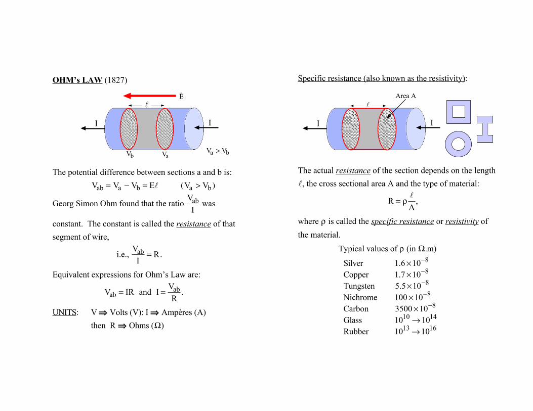
Specific resistance (also known as the resistivity):
The actual resistance of the section depends on the length
ℓ, the cross sectional area A and the type of material:
R = ρ
ℓA
,
where ρ is called the specific resistance or resistivity of
the material.
Typical values of ρ (in Ω.m)
Silver 1.6 ×10⁻⁸
Copper 1.7 ×10⁻⁸
Tungsten 5.5×10⁻⁸
Nichrome 100 ×10−8
Carbon 3500 ×10−8
Glass 1010 →1014
Rubber 1013 →1016
Area A ℓ
II

The resistivity ρ of a material generally varies with temperature:
A: typical metalB: typical semiconductorC: typical superconductor
Consequently, Ohm’s Law is only valid provided the temperature of the material is constant.
T
A
T
B
T
C
Tc
ρ ρ
ρ
However, not all materials and/or devices are “Ohmic”, i.e., obey Ohm’s Law; look at the semiconductor diode below.
“Ohmic”(most metals)slope
=
ΔIΔV
=1R
⇒ constant
Non “Ohmic”
I
V
ΔI ΔV
I
V
“Resistor”
“Diode” I
V
I
V

Work done and power:
Consider a charge δq moving under the influence of the electric field from a → b in a time δt . The work done by the electric field is:
δW = δq(Va − Vb ) = δq.V,where V is the potential difference between a and b, ( Va > Vb). So, the rate the work is done (i.e., the rate at which the system loses energy), i.e., the power, is:
P =
δWδt
= Vδqδt
= VI (Watts.)
Also, using Ohm’s Law: P = I2R =
V2
R.
Va Vb
a b ℓ
II
δq+
" E
Electrical power and energy:
UNITS: P ⇒Joules
s ⇒ watts (W).
1kW = 1000W
P = VI = I2R =
V2
R V = (Va − Vb)
For charges to flow for t seconds, the energy required is:
U = VIt = I2Rt =
V2
Rt (Joules),
which is often dissipated in the form of heat or light, e.g., Hairdryer: 1500WLight bulbs: 25W, 60W, 100W, etc.
Note: You pay FPL for the work done in moving charges around circuits, which appears as the energy produced (⇒ U = P × t).
I I R
Vb Va

Rating: 60W at 120V
Since P =
V2
R, the resistance of the filament in the bulb
is R =
V2
P=
1202
60= 240Ω .
Note: if a potential difference of only 100V is used, the resistance of the filament, R, doesn’t change, but the power does:
P =
V2
R=
1002
240= 41.7W,
i.e., the power dissipated is less so bulb is not as bright.
Lemon
Coppernail
Zincnail
Examples of simple electrical circuits ...
Note: a lemon with copper and zinc nails acts as a battery! Each circuit has a battery and a load (bulb or motor). The batteries provide the potential difference to “move” charges through the load.
Reflector
Bulb
Switchcontact
Switch Batteries
Springcontact
Magnet
+ + - -

Another example of a simple circuit; a 0.47Ω resistor is connected across the terminals of a 9V battery. The battery provides the potential difference to move +ve charge from the
+ve terminal → −ve terminal(high potential) (low potential)
through the resistor (load). So, the direction of the current is from high potential to low potential. Note: from Ohm’s Law:
I =
VR
=9
0.47=19.1A and P = I2R = 172W.
The resistor gets very hot!!
More on simple circuits ...
When the switch is closed, the batteries cause charges to flow through the LOAD (a bulb) and around the circuit. When the switch is opened, the charges can no longer flow around the circuit.
A generic simple circuit:
Note: current does not get “used up” in a circuit. It is the same all the way round even in the LOAD!
R
I I+ -
+ - Switch open
+ -Switch closed
“LOAD”
Flashlight with two batteries

Consider a battery not in a circuit (i.e., not delivering acurrent). If the potential at a is
Va and the potential at b is Vb
(note Va > Vb) then the
potential difference is
Va − Vb = E,
and E is called the electromotive force (emf) of the battery.
Consider a battery in a circuit. Typically, the connecting wires a-c and b-d have negligible resistance compared with the load (R), so:
ΔVac(= IRac )⇒ 0 and ΔVdb(= IRdb)⇒ 0.
∴Va = Vc and Vd = Vb
so the “full” emf is across the load. Example: Consider a flashlight. The resistance of a bulb is ~ 5Ω; the resistance of the connections between the
bulb and the battery is <10−3Ω.
R
I
a b
c d
II
a b E
ΔV = E
+ - Mechanical analog of a simple circuit ...
The source of emf (i.e., the battery) is like an elevator doing work to “lift” charge from a position of low potential ( −ve), Vb, to a position of high potential ( +ve),
Va, where:
E = Va − Vb.
In a mechanical analog, marbles (charges) are “raised” to a point of higher potential energy Vc at c. They fall from
the top of the track, to a position of lower potential Vd at
d, losing potential energy. At the bottom, work is done to “lift” them back to the point of high potential.
a b c d
b
a c
d

Mechanical analog of a battery:
• A battery acts like a “charge elevator” doing work to “move” charges from the −ve to the +ve terminal and raising their potential energy.
• The potential difference ( V) is a fixed quantity so the battery “raises” each charge ( δq) the same amount of potential energy ( δU = δq.V = δW). The total power
required is: P =
δWδt
=δδt
nδqV( ) = VI
• The amount of current supplied, i.e., the rate of flow of charge depends on the rate the elevator moves; faster for more current, slower for less current. The “height” doesn’t change, so V remains constant even though the current changes.
work done by the battery
+
+
Increasingpotential energy
Va
Vb
+++++++
V = Va − Vb δq
-
Question 25.2: Find the power dissipated in a resistor connected across a constant potential difference of 120V if its resistance is 5Ω.

Since the emf of the battery is applied across the load resistor, the current is
I =
VR
=ER
=120 V
5Ω= 24.0 A.
The power dissipated by the 5Ω resistor is:
P = I2R = (24.0 A)2 × 5Ω = 2880 W ⇒ 2.88 kW.
What is the power dissipated by the battery?
P = E × I⇒ (120 V) × (24.0 A) = 2.88 kW.Also, since the “full” emf of the battery is across the resistor:
P =
E2
R=(120 V)2
5Ω= 2.88 kW.
I
+ - I
E = 120 V
5Ω
Let’s look at the potential around the circuit:We’ll start at c and move clockwise
Note that the current is constant around the circuit:
I =
ER
=120 V5 Ω
= 24.0 A.
E = 120 V
5Ω
Vbc = EVda = E
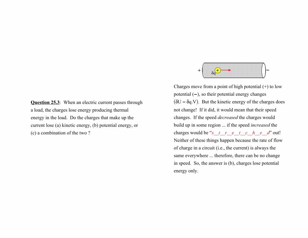
Question 25.3: When an electric current passes through a load, the charges lose energy producing thermal energy in the load. Do the charges that make up the current lose (a) kinetic energy, (b) potential energy, or (c) a combination of the two ?
Charges move from a point of high potential (+) to low potential (−), so their potential energy changes
δU = δq.V( ). But the kinetic energy of the charges does
not change! If it did, it would mean that their speed changes. If the speed decreased the charges would build up in some region ... if the speed increased the charges would be “s__t__r__e__t__c__h__e__d” out! Neither of these things happen because the rate of flow of charge in a circuit (i.e., the current) is always the same everywhere ... therefore, there can be no change in speed. So, the answer is (b), charges lose potential energy only.
+ −+ δq

QUESTION: what happens when we connect different loads (resistors) together? There are two ways they can be connected.
• Example of resistors IN SERIES.
• Examples of resistors IN PARALLEL.
R1 R2 R3
R1 R2 R3
R3
R2
R1
R1
R2
R3
Resistances IN SERIES:
The current through each resistor, R1, R2 and R3, is the
same. An equivalent resistor will produce the same potential difference (V) for the same current (I):
i.e., V = IReq = I(R1 + R2 + R3)
∴Req = R1 + R2 + R3.
In general with resistors in series:
Req = Rii∑ .
R1 R2 R3 I I I I
V
“equivalent resistor”
Req I I
V

Resistors in series ...
Total resistance ⇒ R1 + R2 = 2Ω + 4Ω = 6Ω.
∴I =
ERtotal
=12 V6Ω
= 2.0 A.
Potential difference across R1 ⇒ V1 = IR1
= 4 volts.Potential difference across R2 ⇒ V2 = IR2
= 8 volts.Note: V1 + V2 = 12 volts = E.
Look at the potential difference around the circuit:
V1 = 4 V
V2 = 8 V 12 V
V
X
1 2
I
12 V
2Ω 4Ω
X
Unfortunately, real batteries come with “internal resistance” ... as in this example
Question 25.4: An 11.0Ω resistor is connected across a battery with an emf of 6.00 V and internal resistance
1.00Ω. Find:
(a) the current in the circuit, (b) the voltage across the terminals of the battery, (c) the power supplied by the battery, (d) the power delivered to the external resistor, and (e) the power delivered to the battery’s internal
resistance.

Note the resistors are in series ...
(a) The total resistance in this circuit is:
R = 11Ω +1Ω = 12Ω .
∴I = ER = 6 V
12Ω = 0.5 A.
(With no internal resistance
R = 11Ω and I⇒ 0.55 A.)
(b) The potential difference across battery terminals:
V = E − Ir = (6 V) − (0.5 A ×1Ω) = 5.5 V.Note that this is less than the emf ... the emf of a battery is the potential difference across the battery terminals with no load, i.e., when it not supplying current.
(c) P = EI = (6 V) × (0.5 A) = 3.0 W.
(d) PR = I2R = (0.5 A)2 ×11Ω = 2.75 W.
(e) Pr = I2r = (0.5 A)2 ×1Ω = 0.25 W.
I
E = 6 V, r = 1Ω
+ - I
11Ω
Question 25.5: A battery has an emf equal to 12.0 V and an internal resistance of 4.00 Ω. What value of external resistance R should be placed across the terminals of the battery to obtain maximum power delivered to the resistor?

The power delivered to the resistor is P = I2R, where
I =
E(R + r)
, i.e., P =
E2R(R + r)2
.
For maximum power, dPdR
= 0.
dPdR
=(R + r)2E2 − 2E2R(R + r)
(R + r)4
=(R + r)E2 − 2E2R
(R + r)3=(r −R)E2
(R + r)3.
Hence, dPdR
= 0 when R = r = 4.00Ω. This is the
condition for maximum power. Also true in ac circuits.
I
E = 12.0 V r = 4.00Ω
+ - I
R Resistors IN PARALLEL:
Note: the potential difference across each resistor ( Vi = IiRi) is the same but if R1 ≠ R2 ≠ R3 the current
through each resistor will be different. However,
I = I1 + I2 + I3. (This is Kirchoff’s 1st rule ... later.)
∴I =
VR1
+V
R2+
VR3
=V
Req= V
1R1
+1
R2+
1R3
⎛ ⎝ ⎜ ⎞
⎠ ⎟ ,
i.e.,
1Req
=1
R1+
1R2
+1
R3.
In general, with resistors in parallel,
1Req
=1
Rii∑ .
R1
R2
R3
I I I1
I2
I3
V
“equivalent resistor”
I I Req
V

Question 25.6: If the bulbs and batteries are identical, in which circuit are the bulbs brighter or are they both the same?
(a)(b)
The brightness of a bulb is determined by the power dissipated; the more power, the brighter the bulb.
In (a) the current through each bulb is Ia = E2R.
Therefore, the power dissipated by each bulb in (a) is:
Pa = E2R( )2R = E2
4R.
In (b) since the potential difference across the bulbs is
the same, the current through each bulb is Ib = ER.
Therefore, the power dissipated by each bulb in (b) is:
Pb = ER( )2R = E2
R.
∴Pb = 4Pa ,
so the bulbs are brighter in (b).
(a)(b) Ib
Ib
E E
Ia

Question 25.7: If the bulbs and batteries are identical, which circuit draws most power from the battery?
Assume the batteries have zero internal resistance.
a b c
Let the resistance of each bulb be r. If E is the emf of
each battery, the power dissipated in each circuit is
E2
Rtot,
where Rtot is the total equivalent resistance.
• In (a): Rtot = r.
• In (b):
1Rtot
=1
(r + r)+
1(r + r)
=12r
+12r
=1r.
i.e., Rtot = r.
• In (c):
1Rtot
=13r
+13r
+13r
=33r
=1r.
i.e., Rtot = r.
Since the equivalent resistances of (a), (b) and (c) are the same, the power drawn from the batteries (and the currents) is the same in each case!
a b c

Question 25.8: If the battery in the circuit shown has negligible internal resistance, find
(a) the current in each resistor, and(b) the power delivered by the battery.
3Ω I3
4Ω I1 I2
I4
2Ω 2Ω
(a) First, we calculate I1, but to do that we need the total
resistance of the circuit. We recognize that the right hand group of 3 resistors are all in parallel, so the equivalent resistance is given by:
1Req
=1
2Ω+
12Ω
+1
4Ω=
2 + 2 +14Ω
=5
4Ω.
∴Req = 45Ω = 0.8Ω.
So, here is the equivalent circuit:
The 3Ω resistor is in series with the equivalent resistance of 0.8Ω, so
I1 =
6 V3Ω + 0.8Ω( )
= 1.58 A.
3Ω I3
4Ω I1 I2
I4
2Ω 2Ω
3Ω
I1 6 V 0.8Ω

To determine the currents I2,
I3 and I4 through the parallel combination we need to find the potential difference across them, i.e., Vab. By Ohm’s Law:
Vab = 1.58 A × 0.8Ω = 1.26 V.
The potential difference across each of the three resistors (in parallel) is the same:
∴I2 = 1.26 V2Ω = 0.63 A: I3 = 1.26 V
4Ω = 0.32 A:
I4 = 1.26 V2Ω = 0.63 A.
(Note that: I1 = I2 + I3 + I4 = 1.58 A, which it must since current cannot be lost or gained.)
3Ω
1.58A
6 V 0.8Ω
a
b
2Ω 2Ω
4Ω I2
I3
I4b
a
1.26 V
(b) The power delivered by the battery: P = E I1, where E
is the emf of the battery.
∴P = 6 V ×1.58 A = 9.48 W.
Also, P =
E2
Rtot, where Rtot is the equivalent resistance of
the ensemble of resistors. From (a)
Rtot = 3Ω + 0.8Ω = 3.8Ω.
∴P =
(6 V)2
3.8Ω= 9.47 W.
(Rounding errror.)
You could also calculate the power dissipated by each of
the four resistors, i.e., P = Ii2Rii∑ but it takes more time!

Question 25.9: Four 4Ω resistors are arranged as shown.
(a) What is the equivalent resistance between a and b?
(b) What is the equivalent resistance between a and b if an additional 4Ω resistor was connected across c and d ?
4Ω 4Ω
4Ω 4Ω
a b
c
d
(a)
The circuit is equivalent totwo 8Ω resistors in parallel.
∴
1Req
=1
8Ω+
18Ω
=1
4Ω,
i.e., Req = Rab = 4Ω.
4Ω 4Ω
4Ω 4Ω
a b
c
d
8Ω
8Ω
a b
4Ω 4Ω
4Ω 4Ω
a b
c
d

(b)If we put a battery across a-b, equal currents will flow through c as through d because the two “routes” are identical (a resistance of 8Ω). Since the resistors are all the same ( 4Ω), the potential at c is the same as the potential at d! Therefore, there’s no
potential difference between c and d, so no current will flow through any resistor connected across c-d. As no “extra” current is required from the battery, the equivalent resistance remains the same!
4Ω 4Ω
4Ω 4Ω
a b
c
d
Don’t always look for a formula!!
4Ω 4Ω
4Ω 4Ω
a b
c
d
With more complex circuits, e.g., with more than one source of emf, we must follow certain rules (which we’ve already come across) ...
Kirchhoff’s Rules:
[1] The algebraic sum of currents at a junction is zero, i.e., when currents meet at a junction Iii∑ = 0.
∴ I1 + I2 + I3 − I4 − I5 = 0,
i.e., I1 + I2 + I3 = I4 + I5.
I1
I2
I3
I5
I4

[2] The algebraic sum of the potential differences around a circuit is zero, i.e., around a circuit Vii∑ = 0.
Example ...
Remember Va > Vb and Vc > Vd, i.e., the potential
difference across a resistor decreases in the direction of the current, and across the battery Vf > Ve.
∴E − Vab − Vcd = 0 (Kirchoff’s 2nd rule),
i.e., Vab + Vcd = E.
e d
f a
b c
d
E
Vab
Vcd
V
I E + −
Ia b c d
e f Vab Vcd
Question 25.10: (a) What is the potential difference ΔV across the unknown circuit element in the direction of the current? (b) Which point, X or Y, is at the higher potential?
12V I
6 V
8 V ? ΔV
X
Y
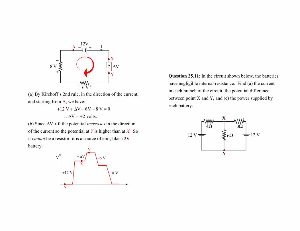
(a) By Kirchoff’s 2nd rule, in the direction of the current, and starting from A, we have:
+12 V + ΔV − 6V − 8 V = 0
∴ΔV = +2 volts.(b) Since ΔV > 0 the potential increases in the direction of the current so the potential at Y is higher than at X. So it cannot be a resistor; it is a source of emf, like a 2V battery.
12V I
6 V
8 V ? ΔV
X
Y
A
V
A
−6 V
−8 V +12 V
+ΔV
X
Y
Question 25.11: In the circuit shown below, the batteries have negligible internal resistance. Find (a) the current in each branch of the circuit, the potential difference between point X and Y, and (c) the power supplied by each battery.
3Ω 4Ω
6Ω 12 V 12 V
Y
X

3Ω 4Ω
6Ω 12 V 12 V
Y
X
I1
I2
I3
A B
I1 I2
I1 I2
I3
(a) Choose the directions of the currents arbitrarily. Using Kirchoff’s rules we have:
I1 = I2 + I3 ... ... ... ... (1)
In circuit A going clockwise (starting at battery):
+12 − 4I1 − 6I3 = 0,
i.e., 4I1 + 6I3 = 12 ... ... ... (2)
12 V 4I1
6I3
+−
+ −
+
− 12 V
3Ω 4Ω
6Ω 12 V 12 V
Y
X
I1
I2
I3
A B
I1 I2
I1 I2
I3
In circuit B we have (starting at X):
−3I2 −12 + 6I3 = 0
i.e., −3I2 + 6I3 = 12 ... ... ... (3)
Using (1), substitute for I1 in (2). Then (2) becomes:
4(I2 + I3) + 6I3 =12
i.e., 4I2 +10I3 = 12 ... ... ... ... (4)
Equations (3) and (4) are a pair of simultaneous linear equations.
12 V 6I3
3I2−
−
−
+
++
12 V

3Ω 4Ω
6Ω 12 V 12 V
Y
X
I1
I2
I3
A B
I1 I2
I1 I2
I3
Solving equations (3) and (4) as a pair of simultaneous linear equations gives:
I2 = −0.90 A and I3 = 1.56 A.
(The negative sign mans we chose the wrong direction for I2!)
∴I1 = (−0.90 A) +1.56 A = 0.66 A.
(b) VXY = I3 × 6Ω = 1.56 A × 6Ω = 9.36 V.
(c) P = EI.
∴PA = 12 V × 0.66 A = 7.92 W,
and PB = 12V × 0.90 A = 10.80 W.
Simple R-C circuit:
Charging the capacitor:
Close S1 and leave S2 open
at t = 0. Charges flow through resistor R and onto the capacitor C. At some
time t, let the charge on the capacitor be q. Using Kirchoff’s 2nd rule: +E − VR − VC = 0,
i.e., i1R +
qC− E = 0,
or dqdt
+q
RC−
ER
= 0.
This is a 1st-order differential equation that tells us how q varies with t.
Initialconditions
R C
S1
S2
+ -E
R C
S1
S2
+E
VR VC
i1 i1 + -
+
-
-

The solution is
q(t) = EC(1− e− t RC )
= QF (1− e− t τ)
where QF (= EC) is the final (maximum) charge and the
quantity τ ( = RC) is called the TIME CONSTANT, which gives us a measure of how quickly the capacitor becomes charged.
When t = τ = RC
q(τ) = QF 1− e−1( ) = 0.632QF.
Also, since VC(t) =
q(t)C
and QF = EC,
then VC(τ) =
0.632QFC
= 0.632E.
QF
q(t)
t
0.632QF
“asymptote”
τ = RC
Since q(t) = EC(1− e− t RC ), the current i1 at any time t is:
i1(t) =
dqdt
=ER
e−t RC
= I!e− t RC = I!e
− t τ ,
where I! ( =E
R) is the initial current in the circuit the
instant S1 is closed.
When t = τ,
i1 = I!e−1 = 0.368I!.
Also VR(t) = i1(t)R.
∴VR (τ) = 0.368E.
Note: when connected across a battery, • an uncharged capacitor “acts” like an short-circuit
so the current is a maximum ( i1(0)⇒ max = I!).
• a fully charged capacitor “acts” like an open-circuit, i.e., an infinite resistance, so the current is zero ( i1(∞)⇒ min = 0).
t
0.368I!
I! =E
R
τ = RC
i1(t) i1(τ)

Discharging the capacitor:
Now, start with a charge Q! on the capacitor and switch
S1 open; so the capacitor is “charged”.
Close S2 at t = 0. The
capacitor discharges so charges (i.e., a current
i2) flows through R.
Then at some time t, we have from Kirchoff’s 2nd rule, in the direction of the arrow (and current i2(t)*):
VC − VR = 0,
i.e., i2(t)R −
qC= 0,
or dqdt
−q
RC= 0.
* Note that i2 during discharging is in the opposite
direction to i1 during charging.
i2
Q! R
C
S1
S2
+E
+ -+
-
-
i2
The solution is:
q(t) = Q!e− t RC
= Q!e− t τ.
When t = τ:
q(τ) = Q!e−t τ = Q!e
−1 = 0.368Q!
Also, since VC(t) =
q(t)C
,
then VC(τ) =
0.368Q!C
.
q(t)
t τ = RC
0.368Q!
Q!

Since q(t) = Q!e− t RC, the current at any time t is:
i2(t) =
dqdt
= −Q!RC
e− t RC = I!e− t τ ,
where I! = −
Q!RC
, i.e., the initial current at t = 0 when S2
is closed.
When t = τ:
i2(τ) = I!e
−t τ =Q!RC
e−1 = 0.368Q!RC
.
Also, since VR(t) = i2(t)R,
then VR(τ) =
0.368Q!C
= VC(τ).
t
0.368I!
i2(t)
τ = RC
I!
During the charging process we have ...
E − VR − VC = 0
i.e., VR + VC = E.
During the discharging process we have ...
VC − VR = 0
i.e., VR = VC.
V(t)
t
τ = RC
E VC
VR
t τ = RC
VR,VC
V(t)

Question 25.12: In the circuit shown below, switch S is opened after having been closed for a long time so the capacitor is fully discharged. Four seconds after S is opened, the potential difference across the resistor is 20.0 V. What is the resistance of the resistor ?
R
+ -50 V
2µF
i(t)
S
With switch S closed, the capacitor is completely uncharged and the potential difference across R is 50 V. When switch S
is opened at t = 0, the capacitor begins to charge and the potential difference across R decreases. When t = 4s,
VR = 20 V, what is the value of R?
We know: VR ⇒ VR (t) = i(t)R = I! Re− t RC.
But initially: VR(0) = I!R = E.
∴VR (t) = Ee− t RC,
i.e., e− t RC = VR( t)
E.
Take natural logarithms of both sides ...
− t
RC = ln VR (t)E( ).
∴−
4s(2 ×10⁻⁶F) ×R
= ln 20 V50 V( ) = −0.916
i.e., R =
4s(2 ×10⁻⁶F) × 0.916
= 2.18 ×10⁶Ω.
The time constant is τ = RC = 4.37s.
R
+ -50 V
2µF
i(t)
S

Energy in a R-C circuit:
During charging, a current flows through the battery and resistor R. The instantaneous power dissipated by the battery is E × i(t).
∴ Total energy dissipated by the battery to fully charge the capacitor is
E i(t).dt =
0
∞∫ E
dqdt.dt =
0
∞∫ E dq
0
QF∫ = QFE.
But, when the capacitor is charged to QF, the energy
stored in the capacitor is 12
QFE. So, using conservation
of energy, the energy dissipated by the resistor is:
QFE −
12
QFE ⇒12
QFE.
work doneby battery
energy storedin capacitor
R C
+ -E
i(t)
R C
+ -E
i(t)
So, during charging, one-half of the energy dissipated by
the battery (= QFE) is stored in the capacitor
=12
QFE⎛ ⎝
⎞ ⎠
and the other half is dissipated by the resistor
=12
QFE⎛ ⎝
⎞ ⎠ .
Note, if the instantaneous current is i(t), the instataneous power dissipated by R is:
PR(t) = i2(t)R,
and the instantaneous power output of the battery is Ei(t). So, the energy stored in the capacitor at time t is
UC(t) = Ei(t) − i2(t)R.