Diploma in Instrumentation and Control Engineering ...webscte.org/PDF/30_3rd_sem_ICE.pdf · Na me...
22
CURRICULAR STRUCTURE FOR PART- II (2 ND YEAR) OF THE FULL TIME DIPLOMA COURSES IN ENGINEERING AND TECHNOLOGY WEST BENGAL STATE COUNCIL OF TECHNICAL EDUCATION TEACHING AND EXAMINATION SCHEME FOR DIPLOMA IN ENGINEERING COURSES COURSE NAME: FULL TIME Diploma in Instrumentation and Control Engineering DURATION OF COURSE: 6 SEMESTERS SEMESTER: THIRD BRANCH: ENGINEERING PERIODS EVALUATION SCHEME SR. NO. SUBJECT CREDITS L TU PR INTERNAL SCHEME TA CT Total ESE PR @TW Total Marks 1. Analog Electronics & Fundamentals 4 3 1 - 10 20 30 70 - - 100 2. Circuit Theory 3 2 1 - 10 20 30 70 - - 100 3 Fundamentals of Instrumentation 3 3 - - 10 20 30 70 - - 100 4. Basic Control System 2 2 1 - 5 10 15 35 - - 50 5. Electrical Measurement & Measuring Instruments 2 2 - - 5 10 15 35 - - 50 6 Electrical Machine 2 2 5 10 15 35 50 7. Analog Electronics & Fundamentals Laboratory 3 - - 3 - - - - 100 - 100 8 Circuit Theory Laboratory 3 - - 3 - - - - 100 - 100 9. Electrical Measurement & Measuring Instruments Laboratory 1 - - 2 - - - - 50 - 50 10. Machine Laboratory 1 - - 2 - - - 50 - 50 11. Environmental Studies - 3 1 1 - 2 - - - - 100 50 - 100 12. Professional Practice – I 1 - - 2 - - - - - 50 50 Total 25 15 3 12 45 90 135 315 300 100 850 STUDENT CONTACT HOURS PER WEEK:33 hrs, (Teaching-15 weeks + Internal Exam-2 weeks ) THEORY AND PRACTICAL PERIODS OF 60 MINUTES EACH. ABBREVIATIONS: L- Lecture, TU- Tutorials, PR- Practical, TA- Teachers Assessment, CT- Class Test, ESE- End Semester Exam, @TW-Term Work TA (Teacher’s assessment) = 10 marks: Attendance & surprise quizzes = 5 marks and Assignment & group discussion = 5 marks for CT= 20 Marks. TA (Teacher’s assessment) = 5 marks: Attendance & surprise quizzes + Assignment & group discussion = 5 marks for CT = 10 Marks. Environmental Studies is a non credit based subject and only internal theoretical examination of 50 marks will be conducted. Total Marks : 850 Minimum passing for Sessional marks is 40%, and for theory subject 40%. Assessment of Practical, Oral & term work to be done as per the prevailing norms of curriculum implementation & assessment.
Transcript of Diploma in Instrumentation and Control Engineering ...webscte.org/PDF/30_3rd_sem_ICE.pdf · Na me...

CURRICULAR STRUCTURE FOR PART- II (2ND
YEAR) OF THE FULL TIME DIPLOMA COURSES
IN ENGINEERING AND TECHNOLOGY
WEST BENGAL STATE COUNCIL OF TECHNICAL EDUCATION
TEACHING AND EXAMINATION SCHEME FOR DIPLOMA IN ENGINEERING COURSES
COURSE NAME: FULL TIME Diploma in Instrumentation and Control Engineering
DURATION OF COURSE: 6 SEMESTERS
SEMESTER: THIRD
BRANCH: ENGINEERING
PERIODS EVALUATION SCHEME SR.
NO. SUBJECT CREDITS L
TU
PR
INTERNAL
SCHEME
TA CT Total
ESE
PR
@TW
Total
Marks
1.
Analog Electronics &
Fundamentals 4 3 1 - 10 20 30 70 - - 100
2. Circuit Theory 3 2 1 - 10 20 30 70 - - 100
3 Fundamentals of
Instrumentation 3 3 - - 10 20 30 70 - - 100
4. Basic Control System
2
2 1
- 5 10 15 35
-
- 50
5.
Electrical Measurement &
Measuring Instruments
2
2
-
-
5 10 15 35 -
-
50
6 Electrical Machine
2
2
5
10
15
35
50
7. Analog Electronics &
Fundamentals Laboratory
3
-
-
3
-
-
-
-
100
-
100
8 Circuit Theory Laboratory
3
-
-
3
-
-
-
-
100
- 100
9. Electrical Measurement &
Measuring Instruments
Laboratory
1
-
-
2
-
-
-
-
50
-
50
10. Machine Laboratory 1 - - 2 - - - 50 - 50
11. Environmental Studies
- 3
1 1
-
2
-
-
-
-
100
50 -
100
12. Professional Practice – I 1 - - 2 - - - - - 50 50
Total 25 15 3 12 45 90 135 315 300 100 850
STUDENT CONTACT HOURS PER WEEK:33 hrs, (Teaching-15 weeks + Internal Exam-2 weeks )
THEORY AND PRACTICAL PERIODS OF 60 MINUTES EACH.
ABBREVIATIONS: L- Lecture, TU- Tutorials, PR- Practical, TA- Teachers Assessment, CT- Class Test, ESE- End Semester Exam,
@TW-Term Work
TA (Teacher’s assessment) = 10 marks: Attendance & surprise quizzes = 5 marks and Assignment & group discussion = 5 marks for CT= 20 Marks.
TA (Teacher’s assessment) = 5 marks: Attendance & surprise quizzes + Assignment & group discussion = 5 marks for CT = 10 Marks.
Environmental Studies is a non credit based subject and only internal theoretical examination of 50 marks will be conducted.
Total Marks : 850
Minimum passing for Sessional marks is 40%, and for theory subject 40%.
Assessment of Practical, Oral & term work to be done as per the prevailing norms of curriculum implementation & assessment.

2
Syllabus for Analog Electronics & Fundamentals
Name of the Course : Diploma in Instrumentation & Control Engineering Name of the subject : Analog Electronics & Fundamentals Subject Code: Semester: Third
Duration: 6 months Maximum Marks: 100
Teaching Scheme: Theory : 3hrs/week
Tutorial : 1hrs/week
Practical : 3hrs/week
Examination Scheme: Internal Scheme : Teachers Assessment: 10
Class Test : 20
End Semester Exam : 70
Credit: 4
Aim:
Sl No. 1 This subject intends to teach operating principle and application of electronic circuits and devices like
different types of amplifiers, oscillators and their applications 2 The subject knowledge is required in Applied Electronics, Instrumentation and communication system 3 Understanding of the subject will provide the student for assembling, trouble shooting & testing of
circuits & devices
Objective: Sl No. The Student will able to 1 do proper biasing for transistor 2 classify and explain various amplifiers and Oscillator circuits based on their characteristics 3 understand the operation and application of differential amplifier and operational amplifier
Pre-requisite: Sl No. 1 Basic Electronic Engineering 2 Basics on different active and passive components
Group Module Topics No. of classes per
module
I Zener Diode:
1. Construction, symbol, Characteristics, biasing,
specification and application of zener diode.
Specifications and examples of zener diode.
02
II Bipolar Junction Transistor:
1. Construction and operation of NPN and PNP
transistor.
2. Cut-off and saturation, V-I characteristics of transistor
in CE, CB and CC configuration. Definition of current
gains and their relationships for three configurations.
3. Application of transistor as amplifier and switch.
Specifications and examples of transistors
06
A
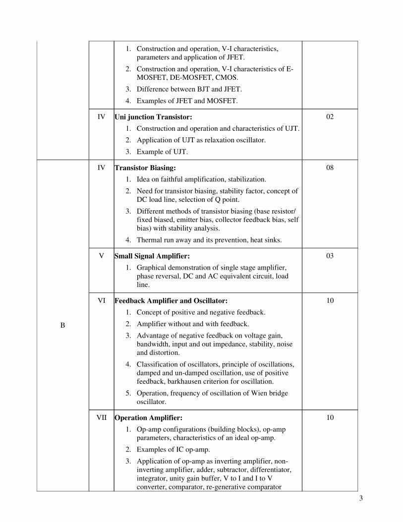
III Field Effect Transistor: 04
3
1. Construction and operation, V-I characteristics,
parameters and application of JFET.
2. Construction and operation, V-I characteristics of E-
MOSFET, DE-MOSFET, CMOS.
3. Difference between BJT and JFET.
4. Examples of JFET and MOSFET.
IV Uni junction Transistor:
1. Construction and operation and characteristics of UJT.
2. Application of UJT as relaxation oscillator.
3. Example of UJT.
02
IV Transistor Biasing:
1. Idea on faithful amplification, stabilization.
2. Need for transistor biasing, stability factor, concept of
DC load line, selection of Q point.
3. Different methods of transistor biasing (base resistor/
fixed biased, emitter bias, collector feedback bias, self
bias) with stability analysis.
4. Thermal run away and its prevention, heat sinks.
08
V Small Signal Amplifier:
1. Graphical demonstration of single stage amplifier,
phase reversal, DC and AC equivalent circuit, load
line.
03
VI Feedback Amplifier and Oscillator:
1. Concept of positive and negative feedback.
2. Amplifier without and with feedback.
3. Advantage of negative feedback on voltage gain,
bandwidth, input and out impedance, stability, noise
and distortion.
4. Classification of oscillators, principle of oscillations,
damped and un-damped oscillation, use of positive
feedback, barkhausen criterion for oscillation.
5. Operation, frequency of oscillation of Wien bridge
oscillator.
10
B
VII Operation Amplifier:
1. Op-amp configurations (building blocks), op-amp
parameters, characteristics of an ideal op-amp.
2. Examples of IC op-amp.
3. Application of op-amp as inverting amplifier, non-
inverting amplifier, adder, subtractor, differentiator,
integrator, unity gain buffer, V to I and I to V
converter, comparator, re-generative comparator
10

4
(Schmitt trigger) and instrumentation amplifier.
Books:
Title Author Publisher
Basic Electronics Subhadeep Choudhury Dhanpat Rai & Co (P) Ltd
Basic Electronics De Pearson Education
Principle of Electronics V K Mehta S. Chand & Co.
Electronic Principle A.P. Malvino McGraw-Hill
Electronic Devices & Circuits Millman & Halkias McGraw-Hill
Basic Electronics & Linear Circuits Bhargava McGraw-Hill
Electronic devices & Circuit Theory Boylestad & Nashalsky Pearson Education
Electronic Fundamentals &
Applications D. Chattopadhyay & P.C. Rakhshit New Age International
End Semester Examination Scheme
Maximum Marks: 70 Time: 3 Hrs
Objective Questions Subjective Questions
Group
Module To be
set
To be
answered
Marks per
question
Total
Marks
To be
set
To be
answered
Marks per
question
Total
Marks
I
II
A
III
12
3
IV
V
VI
B
VII
13
Any 20
1
1 x 20
=20
5
Any 5 taking at
least 2 from each
group
10
10 x 5
=50
5
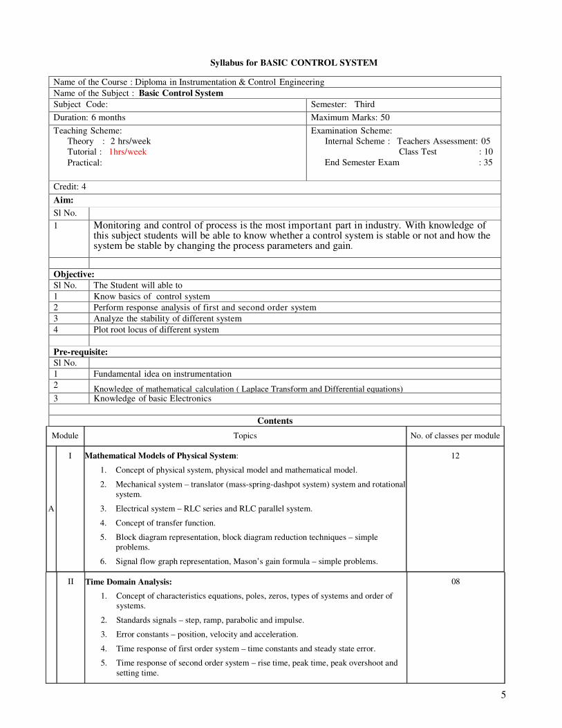
Syllabus for BASIC CONTROL SYSTEM
Name of the Course : Diploma in Instrumentation & Control Engineering Name of the Subject : Basic Control System Subject Code: Semester: Third
Duration: 6 months Maximum Marks: 50
Teaching Scheme:
Theory : 2 hrs/week
Tutorial : 1hrs/week
Practical:
Examination Scheme:
Internal Scheme : Teachers Assessment: 05
Class Test : 10
End Semester Exam : 35
Credit: 4
Aim:
Sl No. 1 Monitoring and control of process is the most important part in industry. With knowledge of
this subject students will be able to know whether a control system is stable or not and how the system be stable by changing the process parameters and gain. .
Objective: Sl No. The Student will able to 1 Know basics of control system 2 Perform response analysis of first and second order system 3 Analyze the stability of different system 4 Plot root locus of different system
Pre-requisite: Sl No. 1 Fundamental idea on instrumentation 2 Knowledge of mathematical calculation ( Laplace Transform and Differential equations) 3 Knowledge of basic Electronics
Contents
Module Topics No. of classes per module
A
I Mathematical Models of Physical System:
1. Concept of physical system, physical model and mathematical model.
2. Mechanical system – translator (mass-spring-dashpot system) system and rotational
system.
3. Electrical system – RLC series and RLC parallel system.
4. Concept of transfer function.
5. Block diagram representation, block diagram reduction techniques – simple
problems.
6. Signal flow graph representation, Mason’s gain formula – simple problems.
12
II Time Domain Analysis:
1. Concept of characteristics equations, poles, zeros, types of systems and order of
systems.
2. Standards signals – step, ramp, parabolic and impulse.
3. Error constants – position, velocity and acceleration.
4. Time response of first order system – time constants and steady state error.
5. Time response of second order system – rise time, peak time, peak overshoot and
setting time.
08

6
B
III Stability Analysis:
1. Concept of stability and S-plane, stability criterions.
2. Different techniques used for stability analysis in time domain (only names).
3. Routh Stability Criterion.
4. Simple problems.
06
IV Root Locus Analysis:
1. Concept of root locus.
2. Construction rules of root locus.
3. Simple problems.
04
Books: Title Author Publisher Process Control Principle & Application S Bhanot Oxford University Press Modern Control Engineering Ogata PHI
Automatic Control System Kuo Wiley India
Modern Control System Ogata PHI
Control System Theory S Dasgupta Khanna
End Semester Examination Scheme
Maximum Marks: 70 Time: 3 Hrs
Objective Questions Subjective Questions Group
Module To be
set To be
answered
Marks per
question Total
Marks To be
set To be
answered Marks per
question Total
Marks 1 A 2
7
4
3 B 4
6
Any 10
1
1 x
10
=10
4
Any 5
taking at
least 2
from each
group
5
5 x 5
=25
7
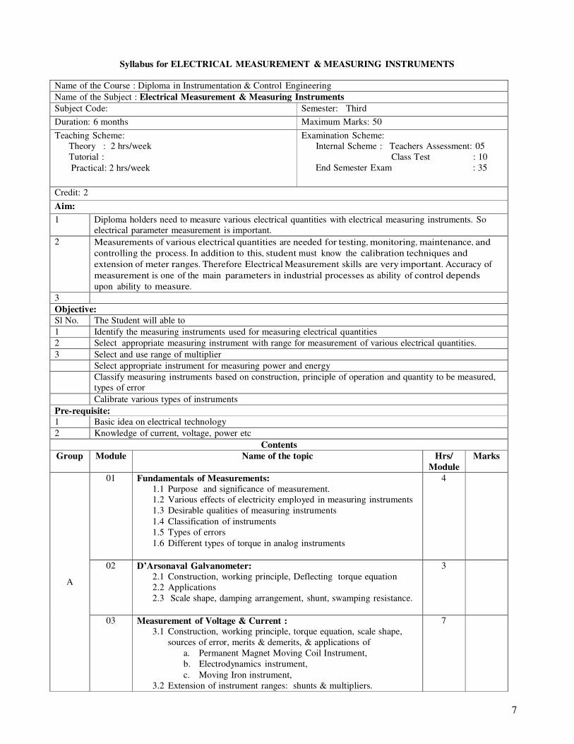
Syllabus for ELECTRICAL MEASUREMENT & MEASURING INSTRUMENTS
Name of the Course : Diploma in Instrumentation & Control Engineering Name of the Subject : Electrical Measurement & Measuring Instruments Subject Code: Semester: Third
Duration: 6 months Maximum Marks: 50
Teaching Scheme:
Theory : 2 hrs/week
Tutorial :
Practical: 2 hrs/week
Examination Scheme:
Internal Scheme : Teachers Assessment: 05
Class Test : 10
End Semester Exam : 35
Credit: 2
Aim:
1 Diploma holders need to measure various electrical quantities with electrical measuring instruments. So
electrical parameter measurement is important. 2 Measurements of various electrical quantities are needed for testing, monitoring, maintenance, and
controlling the process. In addition to this, student must know the calibration techniques and
extension of meter ranges. Therefore Electrical Measurement skills are very important. Accuracy of
measurement is one of the main parameters in industrial processes as ability of control depends
upon ability to measure. 3 Objective: Sl No. The Student will able to 1 Identify the measuring instruments used for measuring electrical quantities 2 Select appropriate measuring instrument with range for measurement of various electrical quantities. 3 Select and use range of multiplier
Select appropriate instrument for measuring power and energy
Classify measuring instruments based on construction, principle of operation and quantity to be measured,
types of error
Calibrate various types of instruments Pre-requisite: 1 Basic idea on electrical technology 2 Knowledge of current, voltage, power etc
Contents Group Module Name of the topic Hrs/
Module Marks
01 Fundamentals of Measurements:
1.1 Purpose and significance of measurement.
1.2 Various effects of electricity employed in measuring instruments
1.3 Desirable qualities of measuring instruments
1.4 Classification of instruments
1.5 Types of errors
1.6 Different types of torque in analog instruments
4
02 D’Arsonaval Galvanometer:
2.1 Construction, working principle, Deflecting torque equation
2.2 Applications
2.3 Scale shape, damping arrangement, shunt, swamping resistance.
3
A
03 Measurement of Voltage & Current : 3.1 Construction, working principle, torque equation, scale shape,
sources of error, merits & demerits, & applications of
a. Permanent Magnet Moving Coil Instrument,
b. Electrodynamics instrument,
c. Moving Iron instrument,
3.2 Extension of instrument ranges: shunts & multipliers.
7

8
04 Measurement of Power & Energy:
4.1 Construction & working principle of –
a. Single-phase dynamometer type wattmeter,
b. Induction type Watt-hour meter (single phase).
4.2 Errors & adjustments of those
4.3 Advantages & disadvantages.
7
B
05 Measurement of Circuit Parameters :
5.1 Classifications of low, medium, high resistance.
5.2 Measurement of Resistance by Wheatstone bridge, Kelvin
Double Bridge & Megger
5.3 Wien’s Bridge
5.4 Maxwell’s Bridge
5.5 Schering Bridge
5.6 Hay bridge
5.7 De-sauté bridge
9
Books:
Title Author Publisher A course in Electrical & Electronics Measurement
& Instrumentation A.K. Sawhney Dhanpat Rai & Co.
A Course in Electrical & Electronics
Measurement & Instrumentation J.B. Gupta S. K.Kataria & Sons
Electrical Measurements & Measuring
Instruments Golding & Widdis A H Wheeler
Electrical & Electronics Measurements and
Instrumentation Purkait, Biswas, Das, Koley McGraw Hill Education
End Semester Examination Scheme Maximum Marks: 35 Time: 2 Hrs
Objective Questions Subjective Questions
Group
Module
To be
set
To be
answered
Marks per
question
Total
Marks
To be
set
To be
answered
Marks
per
question
Total
Marks
1 2
A 3
8
5
4
B 5
5
Any 10
1
1 x 10 =
10
3
Any 5
taking at
least 2 from
each group
5
5 x 5 =
25
Note: Above syllabus is same as that of Diploma in Electronics & Instrumentation Engineering(3
rd Semester)
9
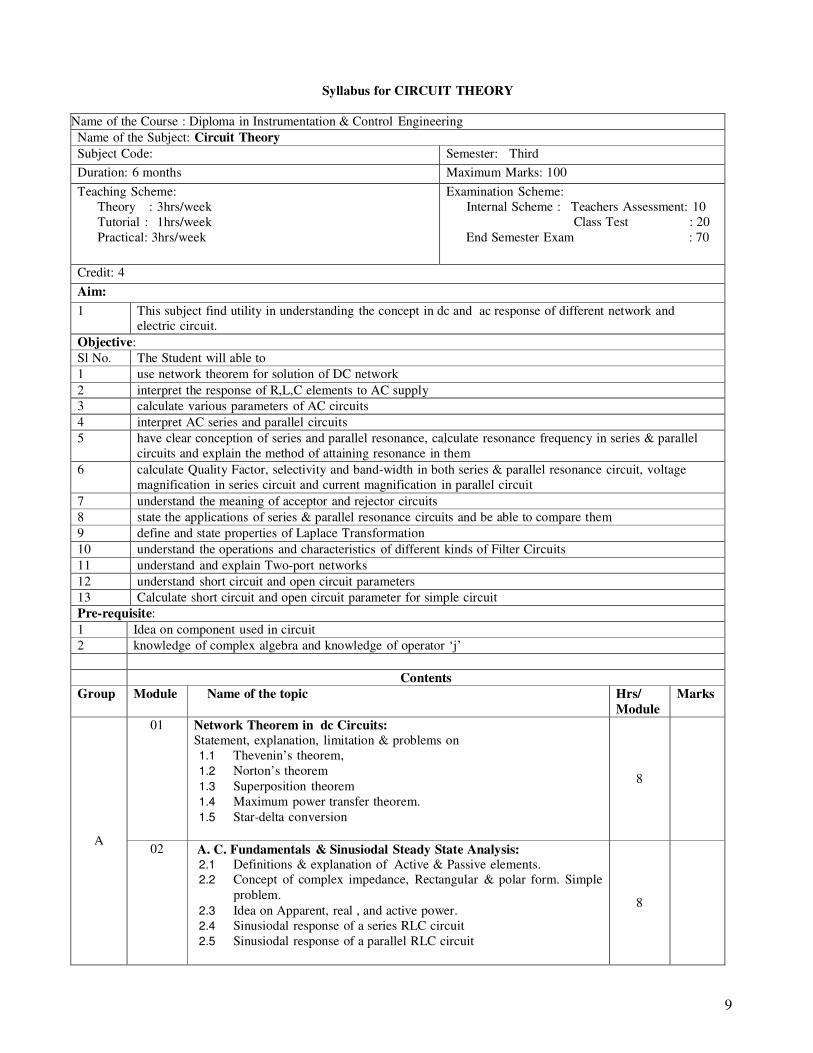
Syllabus for CIRCUIT THEORY
Name of the Course : Diploma in Instrumentation & Control Engineering Name of the Subject: Circuit Theory Subject Code: Semester: Third
Duration: 6 months Maximum Marks: 100
Teaching Scheme:
Theory : 3hrs/week
Tutorial : 1hrs/week
Practical: 3hrs/week
Examination Scheme:
Internal Scheme : Teachers Assessment: 10
Class Test : 20
End Semester Exam : 70
Credit: 4
Aim:
1 This subject find utility in understanding the concept in dc and ac response of different network and
electric circuit. Objective: Sl No. The Student will able to 1 use network theorem for solution of DC network 2 interpret the response of R,L,C elements to AC supply 3 calculate various parameters of AC circuits 4 interpret AC series and parallel circuits 5 have clear conception of series and parallel resonance, calculate resonance frequency in series & parallel
circuits and explain the method of attaining resonance in them 6 calculate Quality Factor, selectivity and band-width in both series & parallel resonance circuit, voltage
magnification in series circuit and current magnification in parallel circuit 7 understand the meaning of acceptor and rejector circuits 8 state the applications of series & parallel resonance circuits and be able to compare them 9 define and state properties of Laplace Transformation 10 understand the operations and characteristics of different kinds of Filter Circuits 11 understand and explain Two-port networks 12 understand short circuit and open circuit parameters 13 Calculate short circuit and open circuit parameter for simple circuit Pre-requisite: 1 Idea on component used in circuit 2 knowledge of complex algebra and knowledge of operator ‘j’
Contents Group Module Name of the topic Hrs/
Module Marks
01 Network Theorem in dc Circuits:
Statement, explanation, limitation & problems on
1.1 Thevenin’s theorem,
1.2 Norton’s theorem
1.3 Superposition theorem
1.4 Maximum power transfer theorem.
1.5 Star-delta conversion
8
A
02 A. C. Fundamentals & Sinusiodal Steady State Analysis: 2.1 Definitions & explanation of Active & Passive elements.
2.2 Concept of complex impedance, Rectangular & polar form. Simple
problem.
2.3 Idea on Apparent, real , and active power.
2.4 Sinusiodal response of a series RLC circuit
2.5 Sinusiodal response of a parallel RLC circuit
8
10
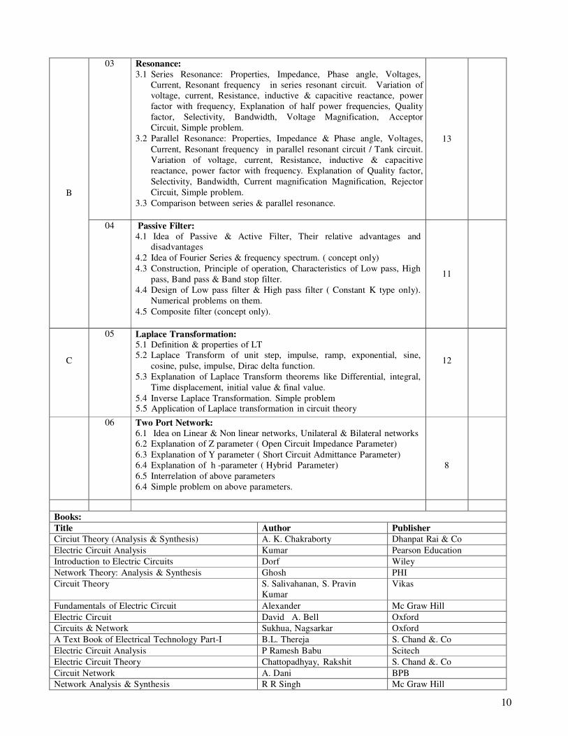
03 Resonance:
3.1 Series Resonance: Properties, Impedance, Phase angle, Voltages,
Current, Resonant frequency in series resonant circuit. Variation of
voltage, current, Resistance, inductive & capacitive reactance, power
factor with frequency, Explanation of half power frequencies, Quality
factor, Selectivity, Bandwidth, Voltage Magnification, Acceptor
Circuit, Simple problem.
3.2 Parallel Resonance: Properties, Impedance & Phase angle, Voltages,
Current, Resonant frequency in parallel resonant circuit / Tank circuit.
Variation of voltage, current, Resistance, inductive & capacitive
reactance, power factor with frequency. Explanation of Quality factor,
Selectivity, Bandwidth, Current magnification Magnification, Rejector
Circuit, Simple problem.
3.3 Comparison between series & parallel resonance.
13
B
04 Passive Filter:
4.1 Idea of Passive & Active Filter, Their relative advantages and
disadvantages
4.2 Idea of Fourier Series & frequency spectrum. ( concept only)
4.3 Construction, Principle of operation, Characteristics of Low pass, High
pass, Band pass & Band stop filter.
4.4 Design of Low pass filter & High pass filter ( Constant K type only).
Numerical problems on them.
4.5 Composite filter (concept only).
11
C
05 Laplace Transformation: 5.1 Definition & properties of LT
5.2 Laplace Transform of unit step, impulse, ramp, exponential, sine,
cosine, pulse, impulse, Dirac delta function.
5.3 Explanation of Laplace Transform theorems like Differential, integral,
Time displacement, initial value & final value. 5.4 Inverse Laplace Transformation. Simple problem
5.5 Application of Laplace transformation in circuit theory
12
06 Two Port Network:
6.1 Idea on Linear & Non linear networks, Unilateral & Bilateral networks
6.2 Explanation of Z parameter ( Open Circuit Impedance Parameter)
6.3 Explanation of Y parameter ( Short Circuit Admittance Parameter)
6.4 Explanation of h -parameter ( Hybrid Parameter)
6.5 Interrelation of above parameters
6.4 Simple problem on above parameters.
8
Books: Title Author Publisher Circiut Theory (Analysis & Synthesis) A. K. Chakraborty Dhanpat Rai & Co Electric Circuit Analysis Kumar Pearson Education Introduction to Electric Circuits Dorf Wiley Network Theory: Analysis & Synthesis Ghosh PHI Circuit Theory S. Salivahanan, S. Pravin
Kumar Vikas
Fundamentals of Electric Circuit Alexander Mc Graw Hill Electric Circuit David A. Bell Oxford Circuits & Network Sukhua, Nagsarkar Oxford A Text Book of Electrical Technology Part-I B.L. Thereja S. Chand &. Co Electric Circuit Analysis P Ramesh Babu Scitech Electric Circuit Theory Chattopadhyay, Rakshit S. Chand &. Co Circuit Network A. Dani BPB Network Analysis & Synthesis R R Singh Mc Graw Hill

11
Electric Circuit Analysis S.N. Sivanandam Vikas
End Semester Examination Scheme
Maximum Marks: 70 Time: 3 Hrs Objective Questions Subjective Questions
Group
Module
To be set
To be
answered
Marks
per
question
Total
Marks
To be set
To be
answered
Marks
per
question
Total
Marks
1
A 2
7
2
3
B 4
9
3
5
Any 5
taking at
least 1
from each
group
10
10 x 5
=50
C 6
9
Any 20
1
1 x 20
=20
3
Note: Above syllabus is same as that of Diploma in Electronics & Instrumentation Engineering(3
rd Semester)
12
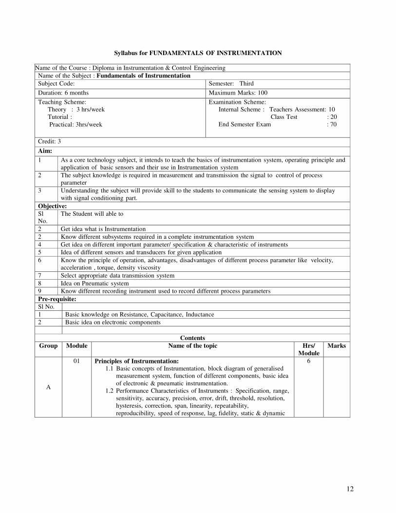
Syllabus for FUNDAMENTALS OF INSTRUMENTATION
Name of the Course : Diploma in Instrumentation & Control Engineering Name of the Subject : Fundamentals of Instrumentation Subject Code: Semester: Third
Duration: 6 months Maximum Marks: 100
Teaching Scheme:
Theory : 3 hrs/week
Tutorial :
Practical: 3hrs/week
Examination Scheme:
Internal Scheme : Teachers Assessment: 10
Class Test : 20
End Semester Exam : 70
Credit: 3
Aim:
1 As a core technology subject, it intends to teach the basics of instrumentation system, operating principle and
application of basic sensors and their use in Instrumentation system 2 The subject knowledge is required in measurement and transmission the signal to control of process
parameter 3 Understanding the subject will provide skill to the students to communicate the sensing system to display
with signal conditioning part. Objective: Sl No.
The Student will able to
2 Get idea what is Instrumentation 2 Know different subsystems required in a complete instrumentation system 4 Get idea on different important parameter/ specification & characteristic of instruments 5 Idea of different sensors and transducers for given application 6 Know the principle of operation, advantages, disadvantages of different process parameter like velocity,
acceleration , torque, density viscosity 7 Select appropriate data transmission system 8 Idea on Pneumatic system 9 Know different recording instrument used to record different process parameters Pre-requisite: Sl No. 1 Basic knowledge on Resistance, Capacitance, Inductance 2 Basic idea on electronic components
Contents
Group Module Name of the topic Hrs/
Module Marks
A
01 Principles of Instrumentation:
1.1 Basic concepts of Instrumentation, block diagram of generalised
measurement system, function of different components, basic idea
of electronic & pneumatic instrumentation.
1.2 Performance Characteristics of Instruments : Specification, range,
sensitivity, accuracy, precision, error, drift, threshold, resolution,
hysteresis, correction, span, linearity, repeatability,
reproducibility, speed of response, lag, fidelity, static & dynamic
6
13
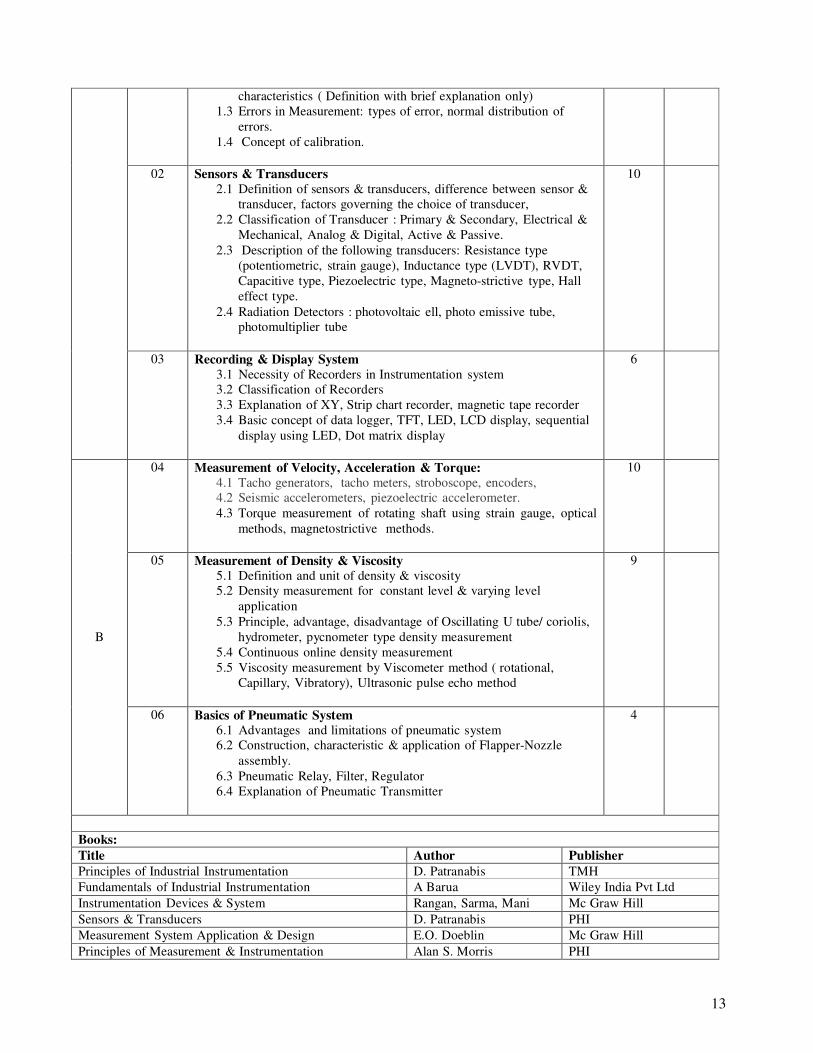
characteristics ( Definition with brief explanation only)
1.3 Errors in Measurement: types of error, normal distribution of
errors.
1.4 Concept of calibration.
02 Sensors & Transducers
2.1 Definition of sensors & transducers, difference between sensor &
transducer, factors governing the choice of transducer,
2.2 Classification of Transducer : Primary & Secondary, Electrical &
Mechanical, Analog & Digital, Active & Passive.
2.3 Description of the following transducers: Resistance type
(potentiometric, strain gauge), Inductance type (LVDT), RVDT,
Capacitive type, Piezoelectric type, Magneto-strictive type, Hall
effect type.
2.4 Radiation Detectors : photovoltaic ell, photo emissive tube,
photomultiplier tube
10
03 Recording & Display System
3.1 Necessity of Recorders in Instrumentation system
3.2 Classification of Recorders
3.3 Explanation of XY, Strip chart recorder, magnetic tape recorder
3.4 Basic concept of data logger, TFT, LED, LCD display, sequential
display using LED, Dot matrix display
6
04 Measurement of Velocity, Acceleration & Torque: 4.1 Tacho generators, tacho meters, stroboscope, encoders,
4.2 Seismic accelerometers, piezoelectric accelerometer.
4.3 Torque measurement of rotating shaft using strain gauge, optical
methods, magnetostrictive methods.
10
05 Measurement of Density & Viscosity 5.1 Definition and unit of density & viscosity
5.2 Density measurement for constant level & varying level
application
5.3 Principle, advantage, disadvantage of Oscillating U tube/ coriolis,
hydrometer, pycnometer type density measurement
5.4 Continuous online density measurement
5.5 Viscosity measurement by Viscometer method ( rotational,
Capillary, Vibratory), Ultrasonic pulse echo method
9
B
06 Basics of Pneumatic System 6.1 Advantages and limitations of pneumatic system
6.2 Construction, characteristic & application of Flapper-Nozzle
assembly.
6.3 Pneumatic Relay, Filter, Regulator
6.4 Explanation of Pneumatic Transmitter
4
Books: Title Author Publisher Principles of Industrial Instrumentation D. Patranabis TMH Fundamentals of Industrial Instrumentation A Barua Wiley India Pvt Ltd Instrumentation Devices & System Rangan, Sarma, Mani Mc Graw Hill Sensors & Transducers D. Patranabis PHI Measurement System Application & Design E.O. Doeblin Mc Graw Hill Principles of Measurement & Instrumentation Alan S. Morris PHI
14
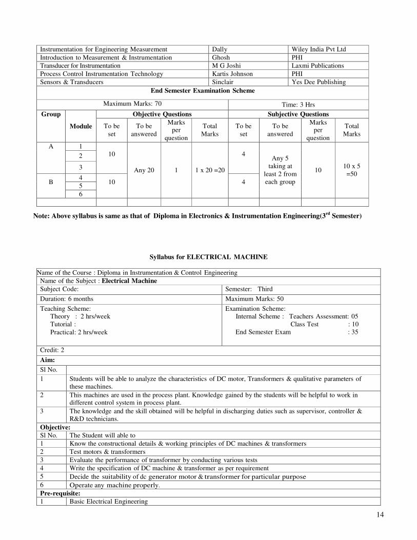
Instrumentation for Engineering Measurement Dally Wiley India Pvt Ltd Introduction to Measurement & Instrumentation Ghosh PHI Transducer for Instrumentation M G Joshi Laxmi Publications
Process Control Instrumentation Technology Kartis Johnson PHI Sensors & Transducers Sinclair Yes Dee Publishing
End Semester Examination Scheme
Maximum Marks: 70 Time: 3 Hrs
Objective Questions Subjective Questions Group
Module
To be
set
To be
answered
Marks per
question
Total
Marks
To be
set
To be
answered
Marks per
question
Total
Marks
1
2
A
3
10
4
4 5
B
6
10
Any 20
1
1 x 20 =20
4
Any 5
taking at
least 2 from
each group
10
10 x 5
=50
Note: Above syllabus is same as that of Diploma in Electronics & Instrumentation Engineering(3
rd Semester)
Syllabus for ELECTRICAL MACHINE
Name of the Course : Diploma in Instrumentation & Control Engineering Name of the Subject : Electrical Machine Subject Code: Semester: Third
Duration: 6 months Maximum Marks: 50
Teaching Scheme:
Theory : 2 hrs/week
Tutorial :
Practical: 2 hrs/week
Examination Scheme:
Internal Scheme : Teachers Assessment: 05
Class Test : 10
End Semester Exam : 35
Credit: 2
Aim:
Sl No. 1 Students will be able to analyze the characteristics of DC motor, Transformers & qualitative parameters of
these machines. 2 This machines are used in the process plant. Knowledge gained by the students will be helpful to work in
different control system in process plant. 3 The knowledge and the skill obtained will be helpful in discharging duties such as supervisor, controller &
R&D technicians. Objective: Sl No. The Student will able to 1 Know the constructional details & working principles of DC machines & transformers 2 Test motors & transformers 3 Evaluate the performance of transformer by conducting various tests 4 Write the specification of DC machine & transformer as per requirement 5 Decide the suitability of dc generator motor & transformer for particular purpose 6 Operate any machine properly. Pre-requisite: 1 Basic Electrical Engineering

15
2 Basic Electronic Engineering Contents
Group Module Name of the topic Hrs/
Module Marks
A
1 Transformer
1.1 Construction & working principle of transformer.
1.2 EMF equation of transformer, transformation ratio, turn ratio,
transformer rating, Simple problem
1.3 Transformer on No Load & on Load
1.4 Open & short circuit test
1.5 Losses & efficiency of transformer, voltage regulation.
1.6 Principle, advantage & disadvantage of Single phase auto-
transformer, Current & Potential transformer, their characteristics.
1.7 Specification of a transformer.
5
2 D.C. Generator 2.1 Construction & working principle of D. C. Generator, EMF
equation.
2.2 Excitation system, types of D.C. Generator, terminal voltage, losses
& efficiency, Specification of DC machine.
3
B 3 D. C. Motor
3.1 Construction & working principle of D. C. Motor.
3.2 Type of motors & their uses
3.3 Explanation of D.C. Motor starters, necessity of starters, types of
starters.
3.4 Speed control of DC Motor by field flux control & armature voltage
control of dc shunt motor.
3.5 Basic idea of enclosure of motor.
3.6 Simple concept of BLDC motor.
8
4 Synchronous Generator (Alternator)
4.1 Construction, Working principle,
4.2 Relation between speed & frequency,
4.3 Pitch factor, Distribution Factor (No derivation required),
4.4 Emf equation of alternator, Simple Problem
4.5 Alternator on No Load & on load,
4.6 Conception on efficiency
4.7 Voltage Regulation (Only definition)
6
C 5 A. C. Motors
5.1 Induction Motor: construction, types of rotor, rotating magnetic
field, principle of operation of three phase induction motor.
5.2 Synchronous speed, actual speed & slip, torque equation, factors
affecting the motor -torque, speed torque characteristics.
5.3 Starting methods of induction motor by using DOL & Star-Delta
starter, basic idea of soft starter.
5.4 Speed control of AC induction motor by variable frequency &
variable voltage (V/F) control.
8
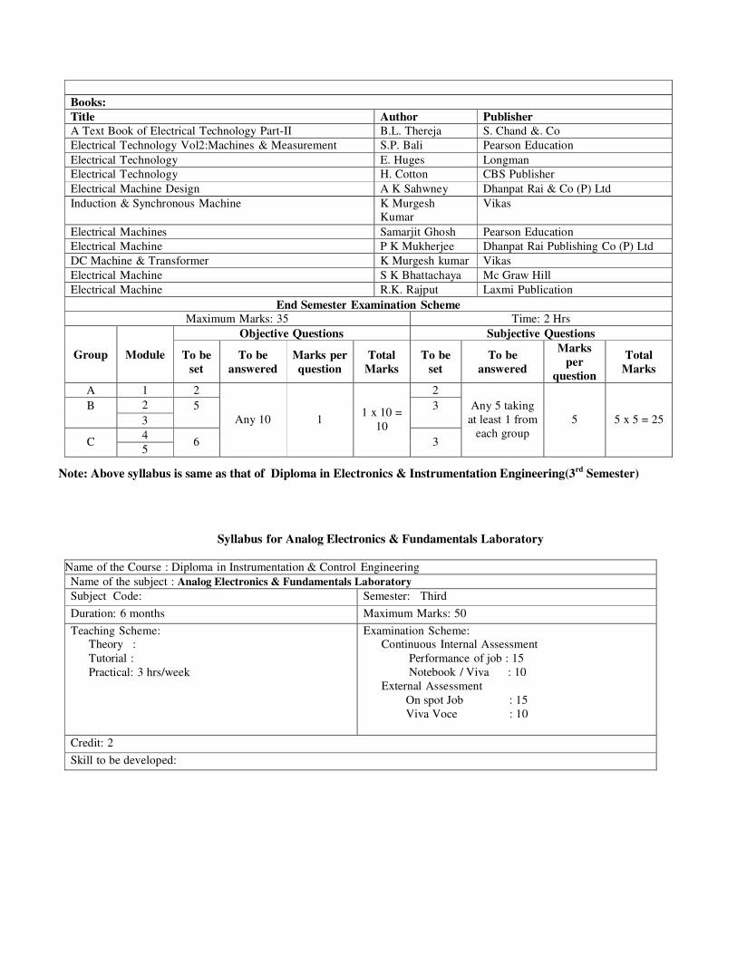
Books: Title Author Publisher A Text Book of Electrical Technology Part-II B.L. Thereja S. Chand &. Co Electrical Technology Vol2:Machines & Measurement S.P. Bali Pearson Education Electrical Technology E. Huges Longman Electrical Technology H. Cotton CBS Publisher Electrical Machine Design A K Sahwney Dhanpat Rai & Co (P) Ltd Induction & Synchronous Machine K Murgesh
Kumar Vikas
Electrical Machines Samarjit Ghosh Pearson Education Electrical Machine P K Mukherjee Dhanpat Rai Publishing Co (P) Ltd DC Machine & Transformer K Murgesh kumar Vikas Electrical Machine S K Bhattachaya Mc Graw Hill Electrical Machine R.K. Rajput Laxmi Publication
End Semester Examination Scheme Maximum Marks: 35 Time: 2 Hrs
Objective Questions Subjective Questions
Group
Module
To be
set
To be
answered
Marks per
question
Total
Marks
To be
set
To be
answered
Marks
per
question
Total
Marks
A 1 2 2 2 B 3
5 3
4
C 5
6
Any 10
1
1 x 10 =
10
3
Any 5 taking
at least 1 from
each group
5
5 x 5 = 25
Note: Above syllabus is same as that of Diploma in Electronics & Instrumentation Engineering(3
rd Semester)
Syllabus for Analog Electronics & Fundamentals Laboratory
Name of the Course : Diploma in Instrumentation & Control Engineering Name of the subject : Analog Electronics & Fundamentals Laboratory Subject Code: Semester: Third
Duration: 6 months Maximum Marks: 50
Teaching Scheme: Theory :
Tutorial :
Practical: 3 hrs/week
Examination Scheme: Continuous Internal Assessment
Performance of job : 15
Notebook / Viva : 10
External Assessment
On spot Job : 15
Viva Voce : 10
Credit: 2
Skill to be developed:

Intellectual Skill
1 To locate fault in circuit
2 Interpret the waveform Motor Skill
1 Ability to sketch circuits 2 Ability to interpret circuit
List of Practical Sl No.
Experiments
1 Identification &testing of different passive and active circuit elements & to know their symbols: Resistor(by using colour code & by using multimeter)
capacitor, inductor, transformer, relay, switches, batteries/cells, diode/Zener diode, transistors, SCR,
DIAC, TRIAC, LED, LCD, photodiode, phototransistors, ICs etc. 2 To plot forward and reverse biased characteristics of zener diode 3 To study a Zener Diode based voltage regulator 4 Experiment for input /output characteristics of BJT
5 Experiment for input & transfer characteristics of FET.
6 Design of Wien bridge oscillator for a given cut off frequency
7 Use of op-amp as – Non inverting amplifier. Inverting amplifier. Buffer. Adder. Differentiator. Integrator.
8 Design of Low pass & High pass active filter & plotting of frequency response
Note: Connect the circuit on bread board and see the response on CRO. Prepare the Labsheet.
Syllabus for CIRCUIT THEORY LABORATORY
Name of the Course : Diploma in Instrumentation & Control Engineering Name of the Subject : Circuit Theory Laboratory Subject Code: Semester: Third
Duration: 6 months Maximum Marks: 100
Teaching Scheme:
Theory :
Tutorial :
Practical: 3 hrs/week
Examination Scheme:
Continuous Internal Assessment
Performance of job : 30
Notebook, Viva : 20
External Assessment
On spot Job : 30
Viva Voce : 20
Credit: 2
Skill to be developed:
Intellectual skill:
1 Interpret results
2 Calculate values of various components for given circuits 3 Select instrument

Motor skill: 1 Connect the instrument properly 2 Take accurate readings
List of practical: Sl No. Experiment 01 Verification of-
Superposition theorem.
Thevenin’s theorem.
Norton’s theorem.
Maximum power transfer theorem. 02 To observe an AC wave form on CRO and calculate its average & RMS values, frequency, time period 03 Analysis of charging & discharging of RC circuit with CRO (calculation of time constant, rise time). 04 Design of series resonance circuit with a particular cut of frequency and to plot frequency response 05 Design of parallel resonance circuit with a particular cut of frequency and to plot frequency response 06 Designing of (considering cut-off frequency) Low pass filter and to plot frequency response.. 07 Designing of (considering cut-off frequency) High pass filter to plot frequency response.
Syllabus for ELECTRICAL MEASUREMENT & MEASURING INSTRUMENTS LABORATORY
Name of the Course : Diploma in Instrumentation & Control Engineering Name of the Subject : Electrical Measurement & Measuring Instruments Laboratory Subject Code: Semester: Third
Duration: 6 months Maximum Marks: 50
Teaching Scheme:
Theory :
Tutorial :
Practical: 2 hrs/week
Examination Scheme:
Continuous Internal Assessment
Performance of job : 15
Notebook, Viva : 10
External Assessment
On spot Job : 15
Viva Voce : 10
Credit: 2
Skill to be developed:
Intellectual Skill:
1 Identification of Instruments
2 Selection of Instruments and equipments for measurement 3 Motor skill: 1 Accuracy in measurement 2 Making proper connection

List of practical Sl No. Experiments
01 Measurement of current and voltage by low range ammeter and voltmeter respectively with shunt and
multiplier 02 Measurement of medium valued resistance by Wheat stone bridge method. 03 Measurement of low valued resistance by Kelvin’s double bridge. 04 Measurement of insulation resistance by Megger. 05 Extension of range of ammeter & voltmeter. 06 Measurement of power & PF by Wattmeter for a load like fluorescent lamp. 07 Measurement of Circuit Parameter using
7.1 Wein Bridge
7.2 Maxwell’s Bridge
7.3 Schering Bridge
7.4 Hay Bridge
7.5 De Saute Bridge
Syllabus for ELECTRICAL MACHINE LABORATORY
Name of the Course : Diploma in Instrumentation & Control Engineering Name of the Subject : Electrical Machine Laboratory Subject Code: Semester: Third
Duration: 6 months Maximum Marks: 50
Teaching Scheme: Theory :
Tutorial :
Practical: 2 hrs/week
Examination Scheme: Continuous Internal Assessment
Performance of job : 15
Notebook, Viva : 10
External Assessment
On spot Job : 15
Viva Voce : 10
Credit: 2
Skill to be developed:
Intellectual Skill:

1 Identification of DC/AC machine, motor, transformer
2 3 Motor skill: 1 Accuracy in measurement 2 Making proper connection
List of practical Sl No. Experiments
1 To identify the construction details of D.C. machine 2 To identify the construction details of A.C. synchronous machine and asynchronous machine 3 Starting and reversing of DC shunt motor 4 Speed control of D.C. shunt motor by-
(a) Armature voltage control.
(b) Field flux control. 5 Measurement of performance of single phase transformer by conducting O.C. and S.C. test 6 Speed control of AC induction motor by V/F drive
Syllabus for PROFESSIONAL PRACTICE I
Name of the Course : Diploma in Instrumentation & Control Engineering Name of the Subject : Professional Practice I Subject Code: Semester: Third
Duration: 6 months Maximum Marks: 50
Teaching Scheme:
Theory :
Tutorial :
Practical: 2 hrs/week
Examination Scheme
(Only Internal Assessment)
Continuous Internal Assessment : 30
Viva/ report/ notebook etc : 20
Credit: 1
Aim:
1 After passing most of the diploma holders join industries. Due to globalization and competition in the
industrial and service sector the selection for job is based on campus interview or competitive tests 2 The purpose of introducing professional practice is to provide opportunity to students to undergo activities
which will enable them to develop confidence. Industrial visits, expert lecturers, seminars on technical topics
and group discussions are planned in a semester so that there will be increased participation of students in
learning process 3 To introduce FOSS Objective: Sl
No. The Student will able to
1 Prepare a report on industrial visit 2 Prepare notes for given topics 3 Present given topic in a seminar

4 Interact with peers to share thought 5 Operate LibraOffice software
Pre-requisite: 1 Knowledge on basic electrical & electronic engineering 2 Knowledge on Instrumentation engineering
Knowledge of basic computer operation Contents
Unit Name of the activity Hrs/Unit
01 Field Visit Structured field visit ( at least one) should be arranged and report the same should be submitted
by the student, as part of term work.
The field visit may be arranged in the following areas / Industries
a) Nearby Petrol Pump (fuel, oil, product specification)
b) Automobile Service Station (Observation of components / aggregates)
c) Dairy Plant / Water Treatment Plant
d) Power supply/ UPS/SMPS/ Inverter manufacturing unit
e) Electronic Instrument calibration laboratory
f) Any other plant
10
02 Lecture by Professional / Industrial experts / Student Seminar Some of the suggested topics are,
8
a) Pollution Control
b) Illumination & lighting System
c) Fire Fighting/ safety Precaution and First Aids
d) Traffic Control System,
e) Nonconventional Energy source.
f) Problems of drinking water in rural areas
g) above or any other suitable topic
03 Group Discussion
The student should discuss in a group of six to eight students and write a brief report on the same
as a part of term work. Two topics for group discussions may be selected by the faculty members.
Some of the suggested topics are-
a) Sports
b) Current news items
c) Discipline & House Keeping
d) Unemployment
f) Illiteracy
g) Dowry Problem
h) Duties and responsibilities of students
e) Futures in Indian Economy
f) Indian Mission to Mars
g) Any other suitable topic
8

04 Free & Open Source Software
(a) Introduction to FOSS
(b) Installation of Libra Office
(c) Getting started with Libra office Writer
Typing text and basic formatting in Writer
Inserting Picture & Objects in Writer document
Viewing & Printing a Text document
(d) Using Different Tools in Writer
Using search replace auto correct
Typing in local languages
Using track changes
Header Footer and notes
Creating newsletter
8
Further suggestion may be submitted to the syllabus committee members by email.
List of the members for the branch of Diploma inDiploma inDiploma inDiploma in Instrumentation and Control Instrumentation and Control Instrumentation and Control Instrumentation and Control
EngineeringEngineeringEngineeringEngineering are:
1) Prof. Bipan Tudu
Dept. of Instrumentation & Electronics Engg.
Jadavpur University
2) JAYANTA KUMAR MODAK
SENIOR MANAGER (POWER STATION)
SAGARDIGHI THERMAL POWER PROJECT
3) Rupa Chatterjee
Lect. In Instrumentation Technology
A P C Ray Polytechnic
4) Pulak Kumar Jana
Lect. In Instrumentation Technology
North Calcutta Polytechnic