DIMENSIONS (MM) MTL4500 - MTL5500 RANGE MTL4500 · DETECTOR INTERFACE 1-channel, with line fault...
38
44 © 2016 Eaton All Rights Reserved Publication No. Eaton Electric Limited, Great Marlings, Butterfield, Luton Beds, LU2 8DL, UK. Tel: + 44 (0)1582 723633 Fax: + 44 (0)1582 422283 E-mail: [email protected] www.mtl-inst.com EUROPE (EMEA): +44 (0)1582 723633 [email protected] THE AMERICAS: +1 800 835 7075 [email protected] ASIA-PACIFIC: +65 6 645 9888 [email protected] The given data is only intended as a product description and should not be regarded as a legal warranty of properties or guarantee. In the interest of further technical developments, we reserve the right to make design changes. MTL4500 - MTL5500 RANGE COMMON SPECIFICATIONS Please go to our website at www.mtl-inst.com for the latest information regarding safety approvals, certificates and entity parameters. Connectors Each unit is supplied with signal connectors, as applicable. When using crimp ferrules for the hazardous or non-hazardous (safe) signal connectors the metal tube length should be 12mm and the wire trim length 14mm. Isolation 250V rms, tested at 1500V rms minimum, between safe- and hazardous-area terminals. MTL4500: 50V between safe-area circuits and power supply MTL5500: 250V rms between safe-area circuits and power supply Supply voltage 20 – 35V dc Location of units Safe area Terminals Accepts conductors of up to 2.5mm 2 stranded or single-core Mounting MTL4500 MTL4500 range of backplanes MTL5500 T-section 35mm DIN rail (7.5 or 15mm) to EN 50022 Ambient temperature limits –20 to +60°C (–6 to +140°F) operating –40 to +80°C (–40 to +176°F) storage Humidity 5 to 95% relative humidity Weight Approximate (except where indicated) MTL4500 140g MTL5500 150g EMC To EN61326 and NE21* * For 20ms power interruption compliance, a suitable power supply must be used. HART® is a registered trademark of HART Communication Foundation DIMENSIONS (MM) MTL4500 16.0mm PITCH HAZ 104.8 15.8 121.8 PWR OPB OPA OPD OPC FLT Optional TH5000 tag holder for individual isolator identification. Accepts tag label 25 x 12.5 ±0.5mm, 0.2mm thick MTL5500 EPSx5CS Rev4 010916
-
Upload
truongquynh -
Category
Documents
-
view
226 -
download
0
Transcript of DIMENSIONS (MM) MTL4500 - MTL5500 RANGE MTL4500 · DETECTOR INTERFACE 1-channel, with line fault...

44
© 2016 EatonAll Rights ReservedPublication No.
Eaton Electric Limited, Great Marlings, Butterfield, LutonBeds, LU2 8DL, UK.Tel: + 44 (0)1582 723633 Fax: + 44 (0)1582 422283E-mail: [email protected]
EUROPE (EMEA):
+44 (0)1582 723633 [email protected]
THE AMERICAS:
+1 800 835 7075 [email protected]
ASIA-PACIFIC:
+65 6 645 9888 [email protected]
The given data is only intended as a product description and should not be regarded as a legal warranty of properties or guarantee. In the interest of further technical developments, we reserve the right to make design changes.
MTL4500 - MTL5500 RANGE COMMON SPECIFICATIONS
Please go to our website at www.mtl-inst.com for the latest information regarding safety approvals, certificates and entity parameters.
ConnectorsEach unit is supplied with signal connectors, as applicable.When using crimp ferrules for the hazardous or non-hazardous (safe) signal connectors the metal tube length should be 12mm and the wire trim length 14mm.
Isolation250V rms, tested at 1500V rms minimum, between safe- and hazardous-area terminals.MTL4500: 50V between safe-area circuits and power supplyMTL5500: 250V rms between safe-area circuits and power supply
Supply voltage20 – 35V dc
Location of unitsSafe area
TerminalsAccepts conductors of up to 2.5mm2 stranded or single-core
MountingMTL4500
MTL4500 range of backplanesMTL5500
T-section 35mm DIN rail (7.5 or 15mm) to EN 50022Ambient temperature limits
–20 to +60°C (–6 to +140°F) operating–40 to +80°C (–40 to +176°F) storage
Humidity5 to 95% relative humidity
WeightApproximate (except where indicated)
MTL4500 140gMTL5500 150g
EMCTo EN61326 and NE21*
* For 20ms power interruption compliance, a suitable power supply must be used.
HART® is a registered trademark of HART Communication Foundation
DIMENSIONS (MM)
MTL4500
16.0mm PITCH
HAZ
104.8 15.8
121.
8
PW
R
OPB
OPA
OPD
OPC
FLT
Optional TH5000 tag holder for individual isolator identification.Accepts tag label 25 x 12.5 ±0.5mm, 0.2mm thick
MTL5500
EPSx5CS Rev4 010916

4
© 2017 EatonAll Rights ReservedPublication No.
Eaton Electric Limited, Great Marlings, Butterfield, LutonBeds, LU2 8DL, UK.Tel: + 44 (0)1582 723633 Fax: + 44 (0)1582 422283E-mail: [email protected]
EUROPE (EMEA):
+44 (0)1582 723633 [email protected]
THE AMERICAS:
+1 800 835 7075 [email protected]
ASIA-PACIFIC:
+65 6 645 9888 [email protected]
The given data is only intended as a product description and should not be regarded as a legal warranty of properties or guarantee. In the interest of further technical developments, we reserve the right to make design changes.
MTL4504SWITCH/ PROXIMITYDETECTOR INTERFACE1-channel with LFD and phase reversal
The MTL4504 enables a safe–area load to be controlled, through a relay, by a proximity detector or switch located in a hazardous area. Line faults are signalled through a separate relay and indicated on the top of the module. MTBF information for the LFD relay is available from Eaton to allow the failure rate for the LFD relay to be calculated when used in the critical path with the output relay for safety critical applications. Switches are provided to select phase reversal and to enable the line fault detection.
SPECIFICATIONSee also common specification
Number of channelsOne
Location of switchZone 0, IIC, T6 hazardous areaDiv.1, Group A, hazardous location
Location of proximity detectorZone 0, IIC, T4–6 hazardous area, if suitably certifiedDiv.1, Group A, hazardous location
Hazardous–area inputsInputs conforming to BS EN60947–5–6:2001 standards for proximity detectors (NAMUR)
Voltage applied to sensor7 to 9V dc from 1kΩ ±10%
Input/output characteristicsNormal phase Outputs closed if input > 2.1mA (< 2kΩ in input circuit) Outputs open if input < 1.2mA (> 10kΩ in input circuit)Hysteresis: 200µA (650Ω) nominal
Line fault detection (LFD) (when selected)User-selectable via switches on the side of the unit. Line faults are indicated by an LED. Line fault relay is de-energised and channel output relay de-energised if input line-fault detectedOpen-circuit alarm on if Iin < 50µAOpen-circuit alarm off if Iin > 250µAShort-circuit alarm on if Rin < 100ΩShort-circuit alarm off if Rin > 360ΩNote: Resistors must be fitted when using the LFD facility with a contact input
500Ω to 1kΩ in series with switch 20kΩ to 25kΩ in parallel with switch
Safe-area output Channel: Single pole relay with changeover contactsLFD: Single pole relay with changeover contacts
Note: reactive loads must be adequately suppressed
Relay characteristics
MTL4504
Response time: 10ms maximum
Contact rating (Safe Area):
10W, 0.5A, 35V dc
Contact rating (Zone 2):
10W, 0.5A, 35V dc
LED indicatorsGreen: power indicationYellow: channel status, on when output energisedRed: LFD indication, on when line fault detected
Maximum current consumption 25mA at 24V dc
Power dissipation within unit0.6W at 24V
Safety descriptionUo=10.5V Io=14mA Po=37mW Um = 253V rms or dc
SIL capableThese models have been assessed for use in IEC 61508 functional safety applications. SIL2 capable for a single device (HFT=0) SIL3 capable for multiple devices in safety redundant configurations (HFT=1) See data on MTL web site and refer to the safety manual.
MTL4504
22kΩ
680Ω
+
–
Output
LFD
Switch-type sensorsrequire resistorsif LFD is selected
Vs–Vs+
20 to 35V dc
To earth-leakage detector *
654
321
LFD
987
121110
13 14
Hazardous area Safe area
FSM FUNCTIONAL SAFETY
MANAGEMENT
IEC 61508:2010
EPS4504 Rev6 240517
SIL2
IEC 61508:2010
SIL3
IEC 61508:2010

6
© 2017 EatonAll Rights ReservedPublication No.
Eaton Electric Limited, Great Marlings, Butterfield, LutonBeds, LU2 8DL, UK.Tel: + 44 (0)1582 723633 Fax: + 44 (0)1582 422283E-mail: [email protected]
EUROPE (EMEA):
+44 (0)1582 723633 [email protected]
THE AMERICAS:
+1 800 835 7075 [email protected]
ASIA-PACIFIC:
+65 6 645 9888 [email protected]
The given data is only intended as a product description and should not be regarded as a legal warranty of properties or guarantee. In the interest of further technical developments, we reserve the right to make design changes.
MTL4510B – MTL5510B SWITCH/ PROXIMITY DETECTOR INTERFACE4-channel, multi-function, digital input
The MTL4510B enables four solid-state outputs in the safe area to be controlled by up to four switches or proximity detectors located in a hazardous area. Each pair of output transistors shares a common terminal and can switch +ve or –ve polarity signals. A range of module configurations is available (see Table 1) through the use of selector switches. These include start/stop operations and pulse output modes.
SPECIFICATIONSee also common specification
Number of channels4, configured by switches
Location of switchesZone 0, IIC, T6 hazardous areaDiv 1, Group A hazardous location
Location of proximity detectorsZone 0, IIC, T4-6 hazardous area if suitably certifiedDiv 1, Group A, hazardous location
Hazardous-area inputsInputs conforming to BS EN60947–5–6:2001 standards for proximity detectors (NAMUR)
Voltage applied to sensor7 to 9V dc from 1kΩ ±10%
Input/output characteristicsNormal phase Outputs closed if input > 2.1mA (< 2kΩ in input circuit) Outputs open if input < 1.2mA (> 10kΩ in input circuit)Hysteresis: 200µA (650Ω) nominal
Line fault detection (LFD) (when selected)User-selectable via switches on the side of the unit. Open-circuit alarm on if Iin < 50µAOpen-circuit alarm off if Iin > 250µAShort-circuit alarm on if Rin < 100ΩShort-circuit alarm off if Rin > 360ΩNote: Resistors must be fitted when using the LFD facility with a contact input
500Ω to 1kΩ in series with switch 20kΩ to 25kΩ in parallel with switch
Safe-area outputs Floating solid-state outputs compatible with logic circuitsOperating frequency: dc to 500HzMax. off-state voltage: ± 35VMax. off-state leakage current: ± 50µAMax. on-state resistance: 25ΩMax. on-state current: ± 50mA
LED indicatorsGreen: power indicationYellow: four: on when output activeRed: LFD indication + faulty channel’s yellow LED flashes
Maximum current consumption 40mA at 24V (with all output channels energised)
Power dissipation within unit0.96W at 24V, with 10mA loads
Safety description (each channel)Uo=10.5V Io=14mA Po=37mW Um = 253V rms or dc
Table 1 - Mode options
MODE Function Equivalent*
0 4-ch switch input, MTLx510
1 2-ch each channel one input, two outputs MTL4016
2 As mode 1 but with phase reversed on all outputs MTL4016
3 2-ch, 2-pole changeover output
4 1-ch with line fault output MTLx014
5 As mode 4 with changeover outputs
6 1-ch with start-stop latch MTL2210B
7 As mode 2 but with LFD enabled on both inputs MTL4016
8 4-ch switch input, MTLx510
9 2-ch with line fault output MTLx017
10 As mode 9 with LFD changeover
11 As mode 10 with phase reversed
12 3-ch with normally-open LFD output
13 3-ch with normally-closed LFD output
14 2-ch monostable, pulse stretcher
15 4-ch switch input MTLx510
* Note: that terminal connections may not be the same on these models, and x can mean either '4' or '5'.
See Instruction Manual INM4500 or INM5500 for further mode information.
Hazardous area Safe area
Ch B
Vs–Vs+
20 to 35V dc
–+–
–+–
Ch D
Ch C
Ch A
1
2
3
4
common
common
Outputs
654
321
789
101112
1314
MTL5510B
MTL4510B
Hazardous area Safe area
Ch B –+–
–+–
Ch D
Ch C
Ch A
1
2
3
4
common
common
Outputs
Vs–Vs+
20 to 35V dc
654
321
987
121110
13 14
EPSx510B Rev5 150517

7
© 2016 EatonAll Rights ReservedPublication No.
Eaton Electric Limited, Great Marlings, Butterfield, LutonBeds, LU2 8DL, UK.Tel: + 44 (0)1582 723633 Fax: + 44 (0)1582 422283E-mail: [email protected]
EUROPE (EMEA):
+44 (0)1582 723633 [email protected]
THE AMERICAS:
+1 800 835 7075 [email protected]
ASIA-PACIFIC:
+65 6 645 9888 [email protected]
The given data is only intended as a product description and should not be regarded as a legal warranty of properties or guarantee. In the interest of further technical developments, we reserve the right to make design changes.
MTL4511 – MTL5511 SWITCH/ PROXIMITY DETECTOR INTERFACE1-channel, with line fault detection
The MTLx511 enables a safe-area load to be controlled by a switch or proximity detector located in a hazardous-area. When selected, open or short circuit conditions in the field wiring are detected by the line-fault-detect (LFD) facility and also indicated on the top of the module. Phase reversal for the channel is selected by a switch on the side of the module and output is provided by changeover relay contacts.
SPECIFICATION See also common specification
Number of channelsOne
Location of switchesZone 0, IIC, T6 hazardous areaDiv. 1, Group A hazardous location
Location of proximity detectorZone 0, IIC, T4–6 hazardous area if suitably certifiedDiv. 1, Group A hazardous location
Hazardous-area inputsInputs conforming to BS EN60947–5–6:2001 standards for proximity detectors (NAMUR)
Voltage applied to sensor7 to 9V dc from 1kΩ ±10%
Input/output characteristicsNormal phase
Outputs closed if input > 2.1mA (< 2kΩ in input circuit)Outputs open if input < 1.2mA (> 10kΩ in input circuit)
Hysteresis: 200µA (650Ω) nominalLine fault detection (LFD) (when selected)
User-selectable via switches on the side of the unit. A line fault is indicated by an LED. The channel output relay is de-energised if an input line fault is detected.Open-circuit alarm on if Iin < 50µAOpen-circuit alarm off if Iin > 250µAShort-circuit alarm on if Rin < 100ΩShort-circuit alarm off if Rin > 360ΩNote: Resistors must be fitted when using the LFD facility with a contact input
500Ω to 1kΩ in series with switch 20kΩ to 25kΩ in parallel with switch
Safe-area output Single pole relay with changeover contacts Note: reactive loads must be adequately suppressed
Relay characteristics
MTL4511 MTL5511
Response time: 10ms maximum 10ms maximum
Contact rating (Safe Area):
10W, 0.5A, 35V dc
250V ac, 2A, cosØ >0.7, 40V dc, 2A, resistive load
Contact rating (Zone 2):
10W, 0.5A, 35V dc
35V, 2A, 100VA.
LED indicatorsGreen: power indicationYellow: channel status, on when output energisedRed: LFD indication, on when line fault detected
Maximum current consumption25mA at 24V
Power dissipation within unit0.6W at 24V
Safety description (each channel)Uo=10.5V Io=14mA Po=37mW Um = 253V rms or dc
SIL capableThese models have been assessed for use in IEC 61508 functional safety applications. SIL2 capable for a single device (HFT=0) SIL3 capable for multiple devices in safety redundant configurations (HFT=1) See data on MTL web site and refer to the safety manual.
Hazardous area Safe area
Vs–Vs+
20 to 35V dc
22kΩ
680Ω
+
–Output
Switch-type sensorsrequire resistorsif LFD is selected
654
321
789
101112
1314
MTL5511
MTL4511
Hazardous area Safe area
22kΩ
680Ω
+
–Output
Switch-type sensorsrequire resistorsif LFD is selected
Vs–Vs+
20 to 35V dc
654
321
987
121110
13 14
FSM FUNCTIONAL SAFETY
MANAGEMENT
IEC 61508:2010
EPSx511 Rev6 010916
SIL2
IEC 61508:2010
SIL3
IEC 61508:2010

8
© 2016 EatonAll Rights ReservedPublication No.
Eaton Electric Limited, Great Marlings, Butterfield, LutonBeds, LU2 8DL, UK.Tel: + 44 (0)1582 723633 Fax: + 44 (0)1582 422283E-mail: [email protected]
EUROPE (EMEA):
+44 (0)1582 723633 [email protected]
THE AMERICAS:
+1 800 835 7075 [email protected]
ASIA-PACIFIC:
+65 6 645 9888 [email protected]
The given data is only intended as a product description and should not be regarded as a legal warranty of properties or guarantee. In the interest of further technical developments, we reserve the right to make design changes.
The MTLx513 enables two solid-state outputs in the safe area to be controlled by two switches or proximity detectors located in the hazardous area. The Ch1/Ch2 output transistors share a common terminal and can switch +ve or -ve polarity signals. Independent output phase reversal and line fault detection are enabled via switches for each output. LFD indication is provided on the top of the module.
SPECIFICATIONSee also common specification
Number of channelsTwo
Location of switchesZone 0, IIC, T6 hazardous areaDiv. 1, Group A hazardous location
Location of proximity detectorsZone 0, IIC, T4–6 hazardous area if suitably certifiedDiv. 1, Group A hazardous location
Hazardous-area inputsInputs conforming to BS EN60947–5–6:2001 standards for proximity detectors (NAMUR)
Voltage applied to sensor7 to 9V dc from 1kΩ ±10%
Input/output characteristicsNormal phase
Outputs closed if input > 2.1mA (< 2kΩ in input circuit)Outputs open if input < 1.2mA (> 10kΩ in input circuit)
Hysteresis: 200µA (650Ω) nominalLine fault detection (LFD) (when selected)
User-selectable for each channel via switches on the side of the unit. Line faults are indicated by an LED for each channel. Open-circuit alarm on if Iin < 50µAOpen-circuit alarm off if Iin > 250µAShort-circuit alarm on if Rin < 100ΩShort-circuit alarm off if Rin > 360ΩNote: Resistors must be fitted when using the LFD facility with a contact input
500Ω to 1kΩ in series with switch 20kΩ to 25kΩ in parallel with switch
Phase reversalIndependent for each channel, user-selectable
Safe-area outputs Floating solid-state outputs compatible with logic circuitsOperating frequency: dc to 500HzMax. off-state voltage: ± 35VMax. off-state leakage current: ± 50µAMax. on-state resistance: 25ΩMax. on-state current: ± 50mA
MTL4513 – MTL5513 SWITCH/ PROXIMITY DETECTOR INTERFACE2-channel, line fault detection, phase reversal
LED indicatorsGreen: power indicationYellow: two: channel status, on when output activeRed: two: LFD indication, on when line fault detected
Maximum current consumption30mA at 24V
Power dissipation within unit0.65W typical at 24V, with 10mA loads0.78W max. with 50mA loads
Safety description (each channel)Uo=10.5V Io=14mA Po=37mW Um = 253V rms or dc
Hazardous area Safe area
Vs–Vs+
20 to 35V dc
Ch 1
Ch 2
Outputs
+–
22kΩ
680Ω
+–
Switch-type sensorsrequire resistorsif LFD is selected
22kΩ
680Ω
654
321
789
101112
1314
MTL5513
MTL4513
Hazardous area Safe area
Ch 1
Ch 2
Outputs
+–
22kΩ
680Ω
+
–
22kΩ
680Ω
Vs–Vs+
20 to 35V dcSwitch-type sensorsrequire resistors if LFD is selected
654
321
987
121110
13 14
EPSx513 Rev5 010916

9
© 2016 EatonAll Rights ReservedPublication No.
Eaton Electric Limited, Great Marlings, Butterfield, LutonBeds, LU2 8DL, UK.Tel: + 44 (0)1582 723633 Fax: + 44 (0)1582 422283E-mail: [email protected]
EUROPE (EMEA):
+44 (0)1582 723633 [email protected]
THE AMERICAS:
+1 800 835 7075 [email protected]
ASIA-PACIFIC:
+65 6 645 9888 [email protected]
The given data is only intended as a product description and should not be regarded as a legal warranty of properties or guarantee. In the interest of further technical developments, we reserve the right to make design changes.
MTL4514/B – MTL5514SWITCH/ PROXIMITY DETECTOR INTERFACE1-channel, line fault detection, phase reversal
The MTLx514 enables a safe–area load to be controlled, through a relay, by a proximity detector or switch located in a hazardous area. Line faults are signalled through a separate relay and indicated on the top of the module. Switches are provided to select phase reversal and to enable the line fault detection.
SPECIFICATIONSee also common specification
Number of channelsOne
Location of switchZone 0, IIC, T6 hazardous areaDiv.1, Group A, hazardous location
Location of proximity detectorZone 0, IIC, T4–6 hazardous area, if suitably certifiedDiv.1, Group A, hazardous location
Hazardous–area inputsInputs conforming to BS EN60947–5–6:2001 standards for proximity detectors (NAMUR)
Voltage applied to sensor7 to 9V dc from 1kΩ ±10%
Input/output characteristicsNormal phase
Outputs closed if input > 2.1mA (< 2kΩ in input circuit)Outputs open if input < 1.2mA (> 10kΩ in input circuit)
Hysteresis: 200µA (650Ω) nominalLine fault detection (LFD) (when selected)
User-selectable via switches on the side of the unit. Line faults are indicated by an LED. Line fault relay is energised and channel output relay de-energised if input line-fault detectedOpen-circuit alarm on if Iin < 50µAOpen-circuit alarm off if Iin > 250µAShort-circuit alarm on if Rin < 100ΩShort-circuit alarm off if Rin > 360ΩNote: Resistors must be fitted when using the LFD facility with a contact input
500Ω to 1kΩ in series with switch 20kΩ to 25kΩ in parallel with switch
Safe-area output MTL4514 & MTL5514Channel: Single pole relay with changeover contactsLFD: Single pole relay with changeover contactsMTL4514BChannel: Single pole relayLFD: Single pole relayNote: reactive loads must be adequately suppressed
Relay characteristics
MTL4514/B MTL5514
Response time: 10ms maximum 10ms maximum
Contact rating (Safe Area):
10W, 0.5A, 35V dc
250V ac, 2A, cosØ >0.7, 40V dc, 2A, resistive load
Contact rating (Zone 2):
10W, 0.5A, 35V dc
35V, 2A, 100VA.
LED indicatorsGreen: power indicationYellow: channel status, on when output energisedRed: LFD indication, on when line fault detected
Maximum current consumption 25mA at 24V dc
Power dissipation within unit0.6W at 24V
Safety descriptionUo=10.5V Io=14mA Po=37mW Um = 253V rms or dc
SIL capableThese models have been assessed for use in IEC 61508 functional safety applications. SIL2 capable for a single device (HFT=0) SIL3 capable for multiple devices in safety redundant configurations (HFT=1) See data on MTL web site and refer to the safety manual.
Hazardous area Safe area
Vs–Vs+
20 to 35V dc
22kΩ
680Ω
+
–
Output
LFD
Switch-type sensorsrequire resistorsif LFD is selected
654
321
789
101112
1314
LFD
MTL5514
MTL4514/B
Hazardous area Safe area
FSM FUNCTIONAL SAFETY
MANAGEMENT
IEC 61508:2010
EPSx514 Rev7 010916
SIL2
IEC 61508:2010
SIL3
IEC 61508:2010
680Ω
+
–
Output
LFD
Switch-type sensorsrequire resistorsif LFD is selected
Vs–Vs+
20 to 35V dc
To earth-leakagedetector *
MTL4514 MTL4514B
LFD
Output
654
321
987
121110
LFD
987
121110
13 14
22kΩ

10
© 2016 EatonAll Rights ReservedPublication No.
Eaton Electric Limited, Great Marlings, Butterfield, LutonBeds, LU2 8DL, UK.Tel: + 44 (0)1582 723633 Fax: + 44 (0)1582 422283E-mail: [email protected]
EUROPE (EMEA):
+44 (0)1582 723633 [email protected]
THE AMERICAS:
+1 800 835 7075 [email protected]
ASIA-PACIFIC:
+65 6 645 9888 [email protected]
The given data is only intended as a product description and should not be regarded as a legal warranty of properties or guarantee. In the interest of further technical developments, we reserve the right to make design changes.
MTL4514D – MTL5514DSWITCH/ PROXIMITY DETECTOR INTERFACE1-channel, dual output, LFD, phase reversal
The MTLx514D enables two safe–area loads to be controlled, through relays, by a proximity detector or switch located in a hazardous area. When selected, open or short circuit conditions in the field wiring are detected by the line fault detect (LFD) facility and indicated on the top of the module. Switches are provided to select phase reversal and to enable the line fault detection.
SPECIFICATIONSee also common specification
Number of channelsOne
Location of switchZone 0, IIC, T6 hazardous areaDiv.1, Group A, hazardous location
Location of proximity detectorZone 0, IIC, T4–6 hazardous area, if suitably certifiedDiv.1, Group A, hazardous location
Hazardous–area inputsInputs conforming to BS EN60947–5–6:2001 standards for proximity detectors (NAMUR)
Voltage applied to sensor7 to 9V dc from 1kΩ ±10%
Input/output characteristicsNormal phase
Outputs closed if input > 2.1mA (< 2kΩ in input circuit)Outputs open if input < 1.2mA (> 10kΩ in input circuit)
Hysteresis: 200µA (650Ω) nominalLine fault detection (LFD) (when selected)
User-selectable via switches on the side of the unit. Line faults are indicated by an LED. The channel output relays are de-energised if an input line-fault is detectedOpen-circuit alarm on if Iin < 50µAOpen-circuit alarm off if Iin > 250µAShort-circuit alarm on if Rin < 100ΩShort-circuit alarm off if Rin > 360ΩNote: Resistors must be fitted when using the LFD facility with a contact input
500Ω to 1kΩ in series with switch 20kΩ to 25kΩ in parallel with switch
Safe-area output MTL4514D: two, single pole relays with normally-open contactsMTL5514D: two, single pole relays with changeover contactsNote: reactive loads must be adequately suppressed
Relay characteristics
MTL4514D MTL5514D
Response time: 10ms maximum 10ms maximum
Contact rating (Safe Area):
10W, 0.5A, 35V dc
250V ac, 2A, cosØ >0.7, 40V dc, 2A, resistive load
Contact rating (Zone 2):
10W, 0.5A, 35V dc
35V, 2A, 100VA.
LED indicatorsGreen: power indicationYellow: channel status, on when output energisedRed: LFD indication, on when line fault detected
Maximum current consumption 29mA at 24V dc
Power dissipation within unit0.7W at 24V
Safety descriptionUo=10.5V Io=14mA Po=37mW Um = 253V rms or dc
SIL capableThese models have been assessed for use in IEC 61508 functional safety applications. SIL2 capable for a single device (HFT=0) SIL3 capable for multiple devices in safety redundant configurations (HFT=1) See data on MTL web site and refer to the safety manual
Hazardous area Safe area
Vs–Vs+
20 to 35V dc
22kΩ
680Ω
+
–
Output 1
Switch-type sensorsrequire resistorsif LFD is selected
Output 2654
321
789
101112
1314
MTL5514D
MTL4514D
Hazardous area Safe area
22kΩ
680Ω
+
–Output 1
Switch-type sensorsrequire resistorsif LFD is selected
Vs–Vs+
20 to 35V dc
To earth-leakage detector * Output 2
654
321
987
121110
13 14
FSM FUNCTIONAL SAFETY
MANAGEMENT
IEC 61508:2010
EPSx514D Rev3 010916
SIL2
IEC 61508:2010
SIL3
IEC 61508:2010

12
© 2016 EatonAll Rights ReservedPublication No.
Eaton Electric Limited, Great Marlings, Butterfield, LutonBeds, LU2 8DL, UK.Tel: + 44 (0)1582 723633 Fax: + 44 (0)1582 422283E-mail: [email protected]
EUROPE (EMEA):
+44 (0)1582 723633 [email protected]
THE AMERICAS:
+1 800 835 7075 [email protected]
ASIA-PACIFIC:
+65 6 645 9888 [email protected]
The given data is only intended as a product description and should not be regarded as a legal warranty of properties or guarantee. In the interest of further technical developments, we reserve the right to make design changes.
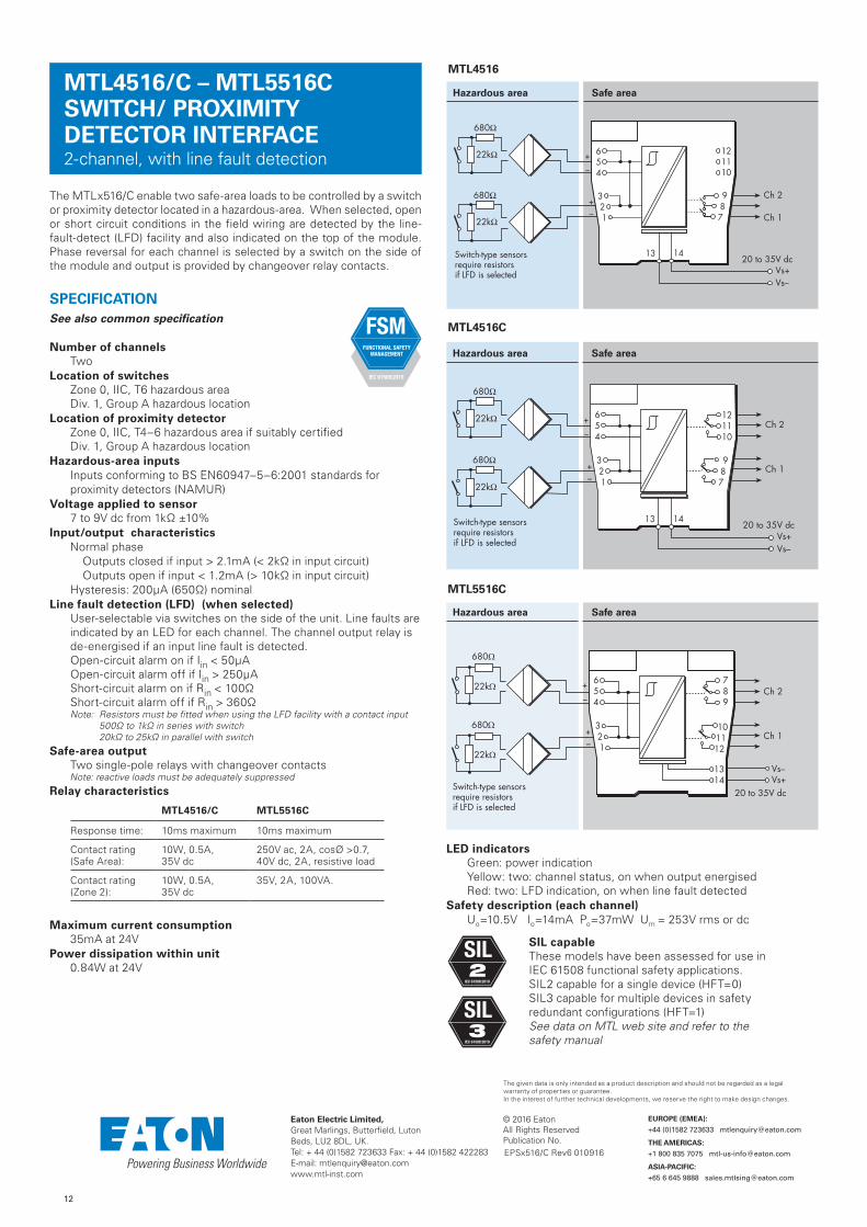
MTL4516/C – MTL5516C SWITCH/ PROXIMITY DETECTOR INTERFACE2-channel, with line fault detection
The MTLx516/C enable two safe-area loads to be controlled by a switch or proximity detector located in a hazardous-area. When selected, open or short circuit conditions in the field wiring are detected by the line-fault-detect (LFD) facility and also indicated on the top of the module. Phase reversal for each channel is selected by a switch on the side of the module and output is provided by changeover relay contacts.
SPECIFICATIONSee also common specification
Number of channelsTwo
Location of switchesZone 0, IIC, T6 hazardous areaDiv. 1, Group A hazardous location
Location of proximity detectorZone 0, IIC, T4–6 hazardous area if suitably certifiedDiv. 1, Group A hazardous location
Hazardous-area inputsInputs conforming to BS EN60947–5–6:2001 standards for proximity detectors (NAMUR)
Voltage applied to sensor7 to 9V dc from 1kΩ ±10%
Input/output characteristicsNormal phase
Outputs closed if input > 2.1mA (< 2kΩ in input circuit)Outputs open if input < 1.2mA (> 10kΩ in input circuit)
Hysteresis: 200µA (650Ω) nominalLine fault detection (LFD) (when selected)
User-selectable via switches on the side of the unit. Line faults are indicated by an LED for each channel. The channel output relay is de-energised if an input line fault is detected.Open-circuit alarm on if Iin < 50µAOpen-circuit alarm off if Iin > 250µAShort-circuit alarm on if Rin < 100ΩShort-circuit alarm off if Rin > 360ΩNote: Resistors must be fitted when using the LFD facility with a contact input
500Ω to 1kΩ in series with switch 20kΩ to 25kΩ in parallel with switch
Safe-area output Two single-pole relays with changeover contactsNote: reactive loads must be adequately suppressed
Relay characteristics
MTL4516/C MTL5516C
Response time: 10ms maximum 10ms maximum
Contact rating (Safe Area):
10W, 0.5A, 35V dc
250V ac, 2A, cosØ >0.7, 40V dc, 2A, resistive load
Contact rating (Zone 2):
10W, 0.5A, 35V dc
35V, 2A, 100VA.
Maximum current consumption35mA at 24V
Power dissipation within unit0.84W at 24V
LED indicatorsGreen: power indicationYellow: two: channel status, on when output energisedRed: two: LFD indication, on when line fault detected
Safety description (each channel)Uo=10.5V Io=14mA Po=37mW Um = 253V rms or dc
SIL capableThese models have been assessed for use in IEC 61508 functional safety applications. SIL2 capable for a single device (HFT=0) SIL3 capable for multiple devices in safety redundant configurations (HFT=1) See data on MTL web site and refer to the safety manual
Hazardous area Safe area
Vs–Vs+
20 to 35V dc
+–
+
–Ch 2
Ch 1
22kΩ
680Ω
22kΩ
680Ω
Switch-type sensorsrequire resistorsif LFD is selected
654
321
789
101112
1314
MTL5516C
MTL4516C
Hazardous area Safe area
+–
+
–Ch 2
Ch 1
22kΩ
680Ω
22kΩ
680Ω
Vs–Vs+
20 to 35V dcSwitch-type sensorsrequire resistorsif LFD is selected
654
321
987
121110
13 14
MTL4516
Hazardous area Safe area
22kΩ
680Ω+–
22kΩ
680Ω
+–
Ch 2
Ch 1
Switch-type sensorsrequire resistorsif LFD is selected
Vs–Vs+
20 to 35V dc
654
321
987
121110
13 14
FSM FUNCTIONAL SAFETY
MANAGEMENT
IEC 61508:2010
EPSx516/C Rev6 010916
SIL2
IEC 61508:2010
SIL3
IEC 61508:2010
12
© 2016 EatonAll Rights ReservedPublication No.
Eaton Electric Limited, Great Marlings, Butterfield, LutonBeds, LU2 8DL, UK.Tel: + 44 (0)1582 723633 Fax: + 44 (0)1582 422283E-mail: [email protected]
EUROPE (EMEA):
+44 (0)1582 723633 [email protected]
THE AMERICAS:
+1 800 835 7075 [email protected]
ASIA-PACIFIC:
+65 6 645 9888 [email protected]
The given data is only intended as a product description and should not be regarded as a legal warranty of properties or guarantee. In the interest of further technical developments, we reserve the right to make design changes.
MTL4516/C – MTL5516C SWITCH/ PROXIMITY DETECTOR INTERFACE2-channel, with line fault detection
The MTLx516/C enable two safe-area loads to be controlled by a switch or proximity detector located in a hazardous-area. When selected, open or short circuit conditions in the field wiring are detected by the line-fault-detect (LFD) facility and also indicated on the top of the module. Phase reversal for each channel is selected by a switch on the side of the module and output is provided by changeover relay contacts.
SPECIFICATIONSee also common specification
Number of channelsTwo
Location of switchesZone 0, IIC, T6 hazardous areaDiv. 1, Group A hazardous location
Location of proximity detectorZone 0, IIC, T4–6 hazardous area if suitably certifiedDiv. 1, Group A hazardous location
Hazardous-area inputsInputs conforming to BS EN60947–5–6:2001 standards for proximity detectors (NAMUR)
Voltage applied to sensor7 to 9V dc from 1kΩ ±10%
Input/output characteristicsNormal phase
Outputs closed if input > 2.1mA (< 2kΩ in input circuit)Outputs open if input < 1.2mA (> 10kΩ in input circuit)
Hysteresis: 200µA (650Ω) nominalLine fault detection (LFD) (when selected)
User-selectable via switches on the side of the unit. Line faults are indicated by an LED for each channel. The channel output relay is de-energised if an input line fault is detected.Open-circuit alarm on if Iin < 50µAOpen-circuit alarm off if Iin > 250µAShort-circuit alarm on if Rin < 100ΩShort-circuit alarm off if Rin > 360ΩNote: Resistors must be fitted when using the LFD facility with a contact input
500Ω to 1kΩ in series with switch 20kΩ to 25kΩ in parallel with switch
Safe-area output Two single-pole relays with changeover contactsNote: reactive loads must be adequately suppressed
Relay characteristics
MTL4516/C MTL5516C
Response time: 10ms maximum 10ms maximum
Contact rating (Safe Area):
10W, 0.5A, 35V dc
250V ac, 2A, cosØ >0.7, 40V dc, 2A, resistive load
Contact rating (Zone 2):
10W, 0.5A, 35V dc
35V, 2A, 100VA.
Maximum current consumption35mA at 24V
Power dissipation within unit0.84W at 24V
LED indicatorsGreen: power indicationYellow: two: channel status, on when output energisedRed: two: LFD indication, on when line fault detected
Safety description (each channel)Uo=10.5V Io=14mA Po=37mW Um = 253V rms or dc
SIL capableThese models have been assessed for use in IEC 61508 functional safety applications. SIL2 capable for a single device (HFT=0) SIL3 capable for multiple devices in safety redundant configurations (HFT=1) See data on MTL web site and refer to the safety manual
Hazardous area Safe area
Vs–Vs+
20 to 35V dc
+–
+
–Ch 2
Ch 1
22kΩ
680Ω
22kΩ
680Ω
Switch-type sensorsrequire resistorsif LFD is selected
654
321
789
101112
1314
MTL5516C
MTL4516C
Hazardous area Safe area
+–
+
–Ch 2
Ch 1
22kΩ
680Ω
22kΩ
680Ω
Vs–Vs+
20 to 35V dcSwitch-type sensorsrequire resistorsif LFD is selected
654
321
987
121110
13 14
MTL4516
Hazardous area Safe area
22kΩ
680Ω+–
22kΩ
680Ω
+–
Ch 2
Ch 1
Switch-type sensorsrequire resistorsif LFD is selected
Vs–Vs+
20 to 35V dc
654
321
987
121110
13 14
FSM FUNCTIONAL SAFETY
MANAGEMENT
IEC 61508:2010
EPSx516/C Rev6 010916
SIL2
IEC 61508:2010
SIL3
IEC 61508:2010

13
© 2016 EatonAll Rights ReservedPublication No.
Eaton Electric Limited, Great Marlings, Butterfield, LutonBeds, LU2 8DL, UK.Tel: + 44 (0)1582 723633 Fax: + 44 (0)1582 422283E-mail: [email protected]
EUROPE (EMEA):
+44 (0)1582 723633 [email protected]
THE AMERICAS:
+1 800 835 7075 [email protected]
ASIA-PACIFIC:
+65 6 645 9888 [email protected]
The given data is only intended as a product description and should not be regarded as a legal warranty of properties or guarantee. In the interest of further technical developments, we reserve the right to make design changes.
MTL4517 – MTL5517 SWITCH/ PROXIMITY DETECTOR INTERFACE2-channel, line fault detection, phase reversal
The MTLx517 enables two safe-area loads to be controlled, through a relay, by proximity detectors or switches located in a hazardous area. Line faults are signalled through a separate relay and indicated on the top of the module. Switches are provided to select phase reversal and to enable the line fault detection.
SPECIFICATIONSee also common specification
Number of channelsTwo
Location of switchZone 0, IIC, T6 hazardous areaDiv.1, Group A, hazardous location
Location of proximity detectorZone 0, IIC, T4–6 hazardous area, if suitably certifiedDiv.1, Group A, hazardous location
Hazardous-area inputsInputs conforming to BS EN60947–5–6:2001 standards for proximity detectors (NAMUR)
Voltage applied to sensor7 to 9V dc from 1kΩ ±10%
Input/output characteristicsNormal phase
Outputs closed if input > 2.1mA (< 2kΩ in input circuit)Outputs open if input < 1.2mA (> 10kΩ in input circuit)
Hysteresis: 200µA (650Ω) nominalLine fault detection (LFD) (when selected)
User selectable by switches on the side of the module. Line faults are indicated by the LED for each channel.Line fault relay is energised and channel output relay de-energised if input line-fault detectedOpen-circuit alarm on if Iin < 50µAOpen-circuit alarm off if Iin > 250µAShort-circuit alarm on if Rin < 100ΩShort-circuit alarm off if Rin > 360ΩNote: Resistors must be fitted when using the LFD facility with a contact input
500Ω to 1kΩ in series with switch 20kΩ to 25kΩ in parallel with switch
Safe-area output Channel: Two single-pole relays with normally open contactsLFD: Single pole relay with changeover contact (MTL4517)
Single pole relay with normally open contact (MTL5517)Note: reactive loads must be adequately suppressed
Relay characteristics
MTL4517 MTL5517
Response time: 10ms maximum 10ms maximum
Contact rating (Safe Area):
10W, 0.5A, 35V dc
250V ac, 2A, cosØ >0.7, 40V dc, 2A, resistive load
Contact rating (Zone 2):
10W, 0.5A, 35V dc
35V, 2A, 100VA.
Maximum current consumption35mA at 24V
Power dissipation within unit0.84W at 24V
LED indicatorsGreen: power indicationYellow: two: channel status, on when output energisedRed: two: LFD indication, on when line fault detected
Safety description (each channel)Uo=10.5V Io=14mA Po=37mW Um = 253V rms or dc
SIL capableThese models have been assessed for use in IEC 61508 functional safety applications. SIL2 capable for a single device (HFT=0) SIL3 capable for multiple devices in safety redundant configurations (HFT=1) See data on MTL web site and refer to the safety manual.
Hazardous area Safe area
Vs–Vs+
20 to 35V dc
LFD
+–
+
–
Switch-type sensorsrequire resistorsif LFD is selected
Ch 2
Ch 1
LFD
22kΩ
680Ω
22kΩ
680Ω
654
321
789
101112
1314
LFD
MTL5517
MTL4517
Hazardous area Safe area
LFD
+–
+
–
Switch-type sensorsrequire resistorsif LFD is selected
122kΩ
680Ω
22kΩ
680Ω
Vs–Vs+
20 to 35V dc
2
654
321
LFD
987
121110
13 14
FSM FUNCTIONAL SAFETY
MANAGEMENT
IEC 61508:2010
EPSx517 Rev6 010916
SIL2
IEC 61508:2010
SIL3
IEC 61508:2010
14
© 2017 EatonAll Rights ReservedPublication No.
Eaton Electric Limited, Great Marlings, Butterfield, LutonBeds, LU2 8DL, UK.Tel: + 44 (0)1582 723633 Fax: + 44 (0)1582 422283E-mail: [email protected]
EUROPE (EMEA):
+44 (0)1582 723633 [email protected]
THE AMERICAS:
+1 800 835 7075 [email protected]
ASIA-PACIFIC:
+65 6 645 9888 [email protected]
The given data is only intended as a product description and should not be regarded as a legal warranty of properties or guarantee. In the interest of further technical developments, we reserve the right to make design changes.
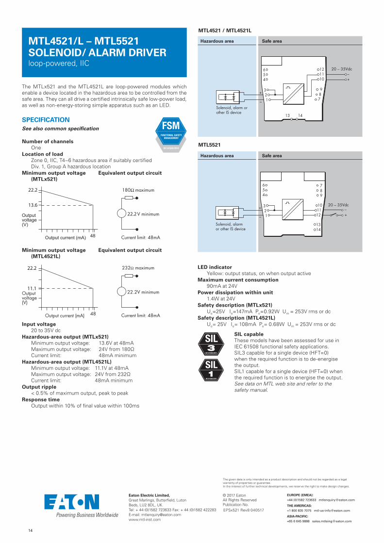
MTL4521/L – MTL5521 SOLENOID/ ALARM DRIVERloop-powered, IIC
The MTLx521 and the MTL4521L are loop-powered modules which enable a device located in the hazardous area to be controlled from the safe area. They can all drive a certified intrinsically safe low-power load, as well as non-energy-storing simple apparatus such as an LED.
SPECIFICATIONSee also common specification
Number of channelsOne
Location of loadZone 0, IIC, T4–6 hazardous area if suitably certifiedDiv. 1, Group A hazardous location
Minimum output voltage Equivalent output circuit(MTLx521)
22.2
22.2
13.6
Minimum output voltage Equivalent output circuit(MTL4521L)
48Output current (mA)
Outputvoltage(V)
22.2V minimum
232Ω
maximum
Current limit: 48mA
22.2
11.1
Input voltage20 to 35V dc
Hazardous-area output (MTLx521)Minimum output voltage: 13.6V at 48mAMaximum output voltage: 24V from 180ΩCurrent limit: 48mA minimum
Hazardous-area output (MTL4521L)Minimum output voltage: 11.1V at 48mAMaximum output voltage: 24V from 232ΩCurrent limit: 48mA minimum
Output ripple< 0.5% of maximum output, peak to peak
Response timeOutput within 10% of final value within 100ms
LED indicatorYellow: output status, on when output active
Maximum current consumption 90mA at 24V
Power dissipation within unit1.4W at 24V
Safety description (MTLx521)Uo=25V Io=147mA Po=0.92W Um = 253V rms or dc
Safety description (MTL4521L)Uo= 25V Io= 108mA Po= 0.68W Um = 253V rms or dc
SIL capableThese models have been assessed for use in IEC 61508 functional safety applications. SIL3 capable for a single device (HFT=0) when the required function is to de-energise the output. SIL1 capable for a single device (HFT=0) when the required function is to energise the output.See data on MTL web site and refer to the safety manual.
Hazardous area Safe area
654
321
789
101112
1314
Solenoid, alarm or other IS device
20 – 35Vdc–+
+
–
MTL5521
MTL4521 / MTL4521L
Hazardous area Safe area
FSM FUNCTIONAL SAFETY
MANAGEMENT
IEC 61508:2010
EPSx521 Rev8 040517
SIL3
IEC 61508:2010
SIL1
IEC 61508:2010

16
© 2017 EatonAll Rights ReservedPublication No.
Eaton Electric Limited, Great Marlings, Butterfield, LutonBeds, LU2 8DL, UK.Tel: + 44 (0)1582 723633 Fax: + 44 (0)1582 422283E-mail: [email protected]
EUROPE (EMEA):
+44 (0)1582 723633 [email protected]
THE AMERICAS:
+1 800 835 7075 [email protected]
ASIA-PACIFIC:
+65 6 645 9888 [email protected]
The given data is only intended as a product description and should not be regarded as a legal warranty of properties or guarantee. In the interest of further technical developments, we reserve the right to make design changes.
With the MTLx523 interface, an on/off device in a hazardous area can be controlled by a volt-free contact or logic signal in the safe area. It is suitable for driving loads such as solenoids. Line fault detection (LFD), which operates irrespective of the output state, is signalled by a safe-area solid-state switch which de-energises MTLx523, or energises MTL4523R, if a field line is open or short–circuited. Earth fault detection can be provided by connecting an MTL4220 earth leakage detector to terminal 3.
SPECIFICATIONSee also common specification
Number of channelsOne
Location of loadZone 0, IIC, T4–6 hazardous area if suitably certifiedDiv. 1, Group A, hazardous location
Minimum output voltage Equivalent output circuit
22.2
22.2
13.6
Hazardous-area outputMinimum output voltage: 13.6V at 48mAMaximum output voltage: 24V from 180ΩMaximum off-state output voltage: 4V from 180ΩCurrent limit: 48mA minimum
Output ripple< 0.5% of maximum output, peak to peak
Control inputSuitable for switch contacts, an open collector transistor or logic drive. (Internal contact wetting voltage 12V @ 0.2mA contact closed. Not suitable for voltage control via series diode.)Output turns on if input switch closed, transistor on or < 1.4V applied across control inputOutput turns off if input switch open, transistor off or > 4.5V applied across control input
Response timeOutput within 10% of final value within 100ms
Line fault detection (LFD)Open or short circuit in field cabling de-energises* solid state line-fault signal. LFD transistor is switched on*, provided that the field circuit impedance is > 55Ω and < 4kΩ. * These conditions are reversed for the MTL4523R. This is to permit parallel connection of alarms between modules to provide a group alarm output.
Line fault signal characteristicsMaximum off-state voltage: 35VMaximum off-state leakage current: 10µAMaximum on-state voltage drop: 2VMaximum on-state current: 50mA
LED indicatorsGreen: power indicationYellow: output status, on when output activeRed: LFD indication, on when line fault detected
Maximum current consumption100mA at 24V dc
Power dissipation within unit1.2W with typical solenoid valve, output on2.0W worst case
Safety descriptionUo=25V Io=147mA Po= 0.92W Um = 253V rms or dc
SIL capableThese models have been assessed for use in IEC 61508 functional safety applications. SIL2 capable for a single device (HFT=0) SIL3 capable for multiple devices in safety redundant configurations (HFT=1) See data on MTL web site and refer to the safety manual.
Hazardous area Safe area
654
321
789
101112
1314
Solenoid, alarm or other IS device
+
–
Vs–Vs+
20 to 35V dc
+–
LFD
+
‡
‡ link to reverse output phase
Control
MTL5523
MTL4523 / MTL4523R
Hazardous area Safe area
654
321
Solenoid, alarm orother IS device
+
–
+
–
LFD†
† MTL4523RLFD phase reversed
Vs–Vs+
20 to 35V dc
Control
+
–987
121110
13 14
FSM FUNCTIONAL SAFETY
MANAGEMENT
IEC 61508:2010
MTL4523/R – MTL5523 SOLENOID/ALARM DRIVERwith line fault detection, IIC
EPSx523/R Rev9 040517
SIL2
IEC 61508:2010
SIL3
IEC 61508:2010
19
© 2017 EatonAll Rights ReservedPublication No.
Eaton Electric Limited, Great Marlings, Butterfield, LutonBeds, LU2 8DL, UK.Tel: + 44 (0)1582 723633 Fax: + 44 (0)1582 422283E-mail: [email protected]
EUROPE (EMEA):
+44 (0)1582 723633 [email protected]
THE AMERICAS:
+1 800 835 7075 [email protected]
ASIA-PACIFIC:
+65 6 645 9888 [email protected]
The given data is only intended as a product description and should not be regarded as a legal warranty of properties or guarantee. In the interest of further technical developments, we reserve the right to make design changes.
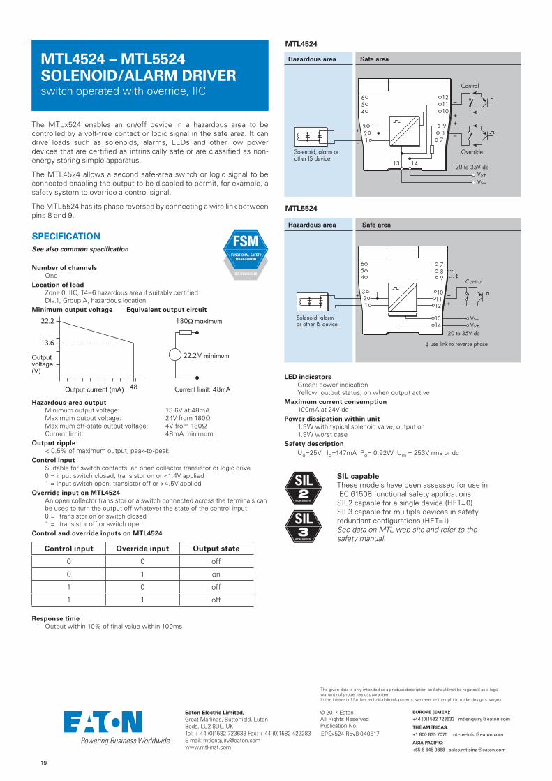
MTL4524 – MTL5524 SOLENOID/ALARM DRIVERswitch operated with override, IIC
The MTLx524 enables an on/off device in a hazardous area to be controlled by a volt-free contact or logic signal in the safe area. It can drive loads such as solenoids, alarms, LEDs and other low power devices that are certified as intrinsically safe or are classified as non-energy storing simple apparatus.
The MTL4524 allows a second safe-area switch or logic signal to be connected enabling the output to be disabled to permit, for example, a safety system to override a control signal.
The MTL5524 has its phase reversed by connecting a wire link between pins 8 and 9.
SPECIFICATIONSee also common specification
Number of channelsOne
Location of loadZone 0, IIC, T4–6 hazardous area if suitably certified Div.1, Group A, hazardous location
Minimum output voltage Equivalent output circuit
22.2
22.2
13.6
Hazardous-area outputMinimum output voltage: 13.6V at 48mAMaximum output voltage: 24V from 180ΩMaximum off-state output voltage: 4V from 180ΩCurrent limit: 48mA minimum
Output ripple< 0.5% of maximum output, peak-to-peak
Control inputSuitable for switch contacts, an open collector transistor or logic drive0 = input switch closed, transistor on or <1.4V applied1 = input switch open, transistor off or >4.5V applied
Override input on MTL4524 An open collector transistor or a switch connected across the terminals can be used to turn the output off whatever the state of the control input 0 = transistor on or switch closed1 = transistor off or switch open
Control and override inputs on MTL4524
Control input Override input Output state
0 0 off
0 1 on
1 0 off
1 1 off
Response timeOutput within 10% of final value within 100ms
LED indicatorsGreen: power indicationYellow: output status, on when output active
Maximum current consumption100mA at 24V dc
Power dissipation within unit1.3W with typical solenoid valve, output on1.9W worst case
Safety descriptionUo=25V Io=147mA Po= 0.92W Um = 253V rms or dc
SIL capableThese models have been assessed for use in IEC 61508 functional safety applications. SIL2 capable for a single device (HFT=0) SIL3 capable for multiple devices in safety redundant configurations (HFT=1) See data on MTL web site and refer to the safety manual.
MTL4524
Hazardous area Safe area
654
321
Solenoid, alarm orother IS device
+
–
+
–
Vs–Vs+
20 to 35V dc
Control
+
–
Override
987
121110
13 14
MTL5524
Hazardous area Safe area
654
321
789
101112
1314
Solenoid, alarm or other IS device
+
–
Vs–Vs+
20 to 35V dc
+–
Control‡
‡ use link to reverse phase
FSM FUNCTIONAL SAFETY
MANAGEMENT
IEC 61508:2010
EPSx524 Rev8 040517
SIL2
IEC 61508:2010
SIL3
IEC 61508:2010

21
© 2017 EatonAll Rights ReservedPublication No.
Eaton Electric Limited, Great Marlings, Butterfield, LutonBeds, LU2 8DL, UK.Tel: + 44 (0)1582 723633 Fax: + 44 (0)1582 422283E-mail: [email protected]
EUROPE (EMEA):
+44 (0)1582 723633 [email protected]
THE AMERICAS:
+1 800 835 7075 [email protected]
ASIA-PACIFIC:
+65 6 645 9888 [email protected]
The given data is only intended as a product description and should not be regarded as a legal warranty of properties or guarantee. In the interest of further technical developments, we reserve the right to make design changes.
MTL4525 – MTL5525 SOLENOID/ALARM DRIVERswitch operated with override, IIC, low power
The MTLx525 enables an on/off device in a hazardous area to be controlled by a volt-free contact or logic signal in the safe area. It can drive loads such as solenoids, alarms, LEDs and other low power devices that are certified as intrinsically safe or are classified as non-energy storing simple apparatus.
The MTL4525 allows a second safe-area switch or logic signal to be connected that enables the output to be disabled to permit, for example, a safety system to override a control signal.
SPECIFICATIONSee also common specification
Number of channelsOne
Location of loadZone 0, IIC, T4–6 hazardous area if suitably certified Div.1, Group A, hazardous location
Minimum output voltage Equivalent output circuit
22.2
22.27.8
Hazardous-area outputMinimum output voltage: 7.8V at 48mAMaximum output voltage: 24V from 300ΩMaximum off-state output voltage: 4V from 300ΩCurrent limit: 48mA minimum
Output ripple< 0.5% of maximum output, peak-to-peak
Control input on MTL4525Suitable for switch contacts, an open collector transistor or logic drive0 = input switch closed, transistor on or < 1.4V applied1 = input switch open, transistor off or > 4.5V applied
Override input on MTL4525An open collector transistor or a switch connected across the terminals can be used to turn the output off whatever the state of the control input 0 = transistor on or switch closed1 = transistor off or switch open
Control and override inputs on MTL4525
Control input Override input Output state
0 0 off
0 1 on
1 0 off
1 1 off
Response timeOutput within 10% of final value within 100ms
LED indicatorsGreen: power indicationYellow: output status, on when output active
Maximum current consumption 100mA at 24V dc
Power dissipation within unit1.3W with typical solenoid valve, output on1.9W worst case
Safety descriptionUo=25V Io=83.3mA Po=0.52W Um = 253V rms or dc
SIL capableThese models have been assessed for use in IEC 61508 functional safety applications. SIL2 (SIL3 for MTL5525) capable for a single device (HFT=0) SIL3 capable for multiple devices in safety redundant configurations (HFT=1) See data on MTL web site and refer to the safety manual.
MTL4525
Hazardous area Safe area
654
321
Solenoid, alarm orother IS device
+
–
+
–
Vs–Vs+
20 to 35V dc
Control
+
–
Override
987
121110
13 14
MTL5525
Hazardous area Safe area
654
321
789
101112
1314
Solenoid, alarm or other IS device
20 – 35Vdc–+
+
–
FSM FUNCTIONAL SAFETY
MANAGEMENT
IEC 61508:2010
EPSx525 Rev8 040517
SIL2
IEC 61508:2010
SIL3
IEC 61508:2010

22
© 2016 EatonAll Rights ReservedPublication No.
Eaton Electric Limited, Great Marlings, Butterfield, LutonBeds, LU2 8DL, UK.Tel: + 44 (0)1582 723633 Fax: + 44 (0)1582 422283E-mail: [email protected]
EUROPE (EMEA):
+44 (0)1582 723633 [email protected]
THE AMERICAS:
+1 800 835 7075 [email protected]
ASIA-PACIFIC:
+65 6 645 9888 [email protected]
The given data is only intended as a product description and should not be regarded as a legal warranty of properties or guarantee. In the interest of further technical developments, we reserve the right to make design changes.
MTL4526 – MTL5526 SWITCH-OPERATED RELAY2–channel IS–output
The MTLx526 enables two separate IS circuits in a hazardous area to be contact controlled by one or two, on/off, control signals in a safe area. Applications include the calibration of strain–gauge bridges; changing the polarity (and thereby the tone) of an IS sounder; the testing of IS fire alarms; and the transfer of safe-area signals into an annunciator with IS input terminals not segregated from each other. The output–relay contacts are certified as non–energy–storing apparatus, and can be connected to any IS circuit without further certification, provided that separate IS circuits are such that they would remain safe if connected together.
SPECIFICATIONSee also common specification
Number of channelsTwo, fully floating
Location of control circuitSafe area
Input/output characteristicsContact/Logic mode(Inputs suitable for switch contacts, an open–collector transistor or logic drive)Relay energised if < 450Ω or < 1V appliedRelay de–energised if > 5kΩ or > 2V applied (35V max.)Loop powered modeRelay energised if >20VRelay de-energised if <17V
Power supply failure protectionRelays de–energised if supply fails
Response time25ms nominal
Contacts (suitable for connection to IS circuits)1–pole changeover per channel
Contact rating250V ac, limited to 40V dc for IS applications, 2A(reactive loads must be suppressed)
Contact life expectancy2 x 107 operations at maximum IS load
Relay drive (see switch setting table) Choice of "loop-powered" or "contact/logic" control, for both channels, by switch selection. A further switch option ("1in2out") enables either input, in contact/logic mode, to activate both outputs.
LED indicatorsGreen: power indicationYellow: two: output status, on when relay energised
Power requirement, Vs41mA at 20V dc44mA at 24V dc60mA at 35V dc
Power dissipation within unit1.1W maximum at 24V
Safety description (each channel)Non-energy–storing apparatus: relay contacts may be connected to any IS circuit without further consideration
User switch settings for operating mode
Mode Function SW1 SW2 SW3 SW4
Contact/Logic
Input
2 ch Off On On On
1in2out On On On On
Loop Powered 2 ch Off Off Off Off
MTL4526
MTL5526
Hazardous area Safe area
123
456
IS relay
IS relay
1
2 +
–
+–
All contacts shown in normal position(relays de-energised)
Vs–Vs+
20 to 35V dc
+
–
+–
Control20 to 35V dc
Looppowered
Contactinputs
987
121110
1
2
Sw413 14
Hazardous area Safe area
123
456
789
101112
1314
IS relay
IS relay
1
Vs–Vs+
20 to 35V dc
+
–
2
+
–
Control20 to 35V dc
+–
+–
Looppowered
Contactinputs
All contacts shown in normal position(relays de-energised)
1
2
Sw4
EPSx526 Rev7 010916

23
© 2017 EatonAll Rights ReservedPublication No.
Eaton Electric Limited, Great Marlings, Butterfield, LutonBeds, LU2 8DL, UK.Tel: + 44 (0)1582 723633 Fax: + 44 (0)1582 422283E-mail: [email protected]
EUROPE (EMEA):
+44 (0)1582 723633 [email protected]
THE AMERICAS:
+1 800 835 7075 [email protected]
ASIA-PACIFIC:
+65 6 645 9888 [email protected]
The given data is only intended as a product description and should not be regarded as a legal warranty of properties or guarantee. In the interest of further technical developments, we reserve the right to make design changes.
SIL capableThese models have been assessed for use in IEC 61508 functional safety applications. SIL1 capable for a single device (HFT=0) SIL2 capable for multiple devices in safety redundant configuration (HFT=1) See data on MTL web site and refer to the safety manual.
The MTLx531 repeats a signal from a vibration sensor in a hazardous area, providing an output for a monitoring system in the safe area. The interface is compatible with 3-wire eddy-current probes and accelerometers or 2-wire current sensors; the selection is made by a switch on the side of the module.
SPECIFICATIONSee also common specification
Number of channelsOne
Sensor type2- or 3-wire vibration transducer
Location of signal sourceZone 0, IIC, T4–6 hazardous area if suitably certifiedDiv. 1, Group A hazardous location
Hazardous-area inputInput impedance (terminals 2 & 3): 10kΩ
Transducer supply voltage, 3-wire (terminals 3 & 1)
Output current –20mA
Outputvoltage
–24V
0
350Ω
–17V
Transducer supply current, 2-wire3.3mA (nom.) for 2-wire sensors, user selectable by switch
Signal range Minimum –20V, maximum –0.5V
DC transfer accuracy at 20°C<±50mV
AC transfer accuracy at 20°C0Hz to 1kHz: ±1%1kHz to 10kHz: –5% to +1%10kHz to 20kHz: –10% to +1%
Temperature coefficient±50ppm/°C (10 to 65°C)±100ppm/°C (–20 to 10°C)
Voltage bandwidth –3dB at 47kHz (typical)
Phase response<14µs, equivalent to:–1° at 200Hz–3° at 600Hz–5° at 1kHz–50° at 10kHz–100° at 20kHz
Safe-area output impedance <20Ω
LED indicatorGreen: power indication
Supply voltage20 to 35V dc
Maximum current consumption (10mA transducer load)65mA at 24V
Maximum power dissipation within unit 1.33W
Safety descriptionTerminals 3 to 1Uo=26.6V Io=94mA Po=0.66W Um = 253V rms or dc Terminals 3 to 2Non-energy-storing apparatus ≤1.5V, ≤0.1A and ≤25mW
MTL4531 – MTL5531 VIBRATION TRANSDUCER INTERFACE
Hazardous area Safe area
654
321
Vibrationtransducer
Vibrationtransducer
Vs–Vs+
20 to 35V dc
987
121110
13 14
Monitor
COMSIGV–
–ve
0V
3-wire
2-wire 2
1
3
MTL5531
MTL4531
Hazardous area Safe area
654
321
789
101112
1314
COMSIGV–
Vibrationtransducer
Vibrationtransducer
Vs–Vs+
20 to 35V dc
–ve
0VMonitor
3-wire
2-wire 2
1
3
EPSx531 Rev7 150517
FSM FUNCTIONAL SAFETY
MANAGEMENT
IEC 61508:2010
SIL2
IEC 61508:2010
SIL1
IEC 61508:2010

24
© 2016 EatonAll Rights ReservedPublication No.
Eaton Electric Limited, Great Marlings, Butterfield, LutonBeds, LU2 8DL, UK.Tel: + 44 (0)1582 723633 Fax: + 44 (0)1582 422283E-mail: [email protected]
EUROPE (EMEA):
+44 (0)1582 723633 [email protected]
THE AMERICAS:
+1 800 835 7075 [email protected]
ASIA-PACIFIC:
+65 6 645 9888 [email protected]
The given data is only intended as a product description and should not be regarded as a legal warranty of properties or guarantee. In the interest of further technical developments, we reserve the right to make design changes.
DRAFT
MTL4532 – MTL5532 PULSE ISOLATORpulse & 4/20mA current outputs
The MTLx532 isolates pulses from a switch, proximity detector, current pulse transmitter or voltage pulse transmitter located in a hazardous area. It is ideal for applications involving high pulse rates and fast response times, by repeating the pulses into the safe area. An analogue output proportional to frequency is also provided, together with a relay output, which may be configured to act as an alarm. Configuration is carried out with a personal computer.
SPECIFICATIONSee also common specification
Number of channelsOne, fully floating
Sensor typeSwitch or proximity detector (NAMUR/BS EN 60947–5–6:2001)2– or 3–wire voltage or pulse transmitter
Location of switchZone 0, IIC, T6 hazardous areaDiv. 1, Group A, hazardous location
Location of proximity detector or transmitterZone 0, IIC, T4–T6 if suitably certifiedDiv.1, Group A, hazardous location
InputSwitch input:Output ON if switch is closedProximity detector input:Excitation: 7.0 to 9.0V dc from 1kΩ nominalOutput ON if input > 2.1mA* (< 2kΩ) Output OFF if input < 1.2mA* (> 10kΩ) Switching hysteresis: 0.2mA (650Ω) nominal*NAMUR and BS EN 60947–5–6:2001standardsCurrent pulse input:Transmitter supply: 16.5V dc at 20mAShort circuit current: 24mAOutput: Iin > 9.0mA = ON, Iin < 7.0mA = OFFSwitching hysteresis: 0.5mAVoltage pulse inputInput impedance: > 10kΩSwitching point voltage (Vsp): 3, 6, or 12V nominal(User selectable by switches on the side of the module)Output: Vin > Vsp = ON, Vin < Vsp = OFFSwitching hysteresis: 100mV + (0.1 x Vsp) typical
Safe-area pulse output Maximum delay: 10µsMaximum off–state voltage: 35VMaximum off–state leakage current: 10µAMaximum on–state resistance: 25ΩMaximum on–state current: 50mAOutput OFF if supply failsNote: LFD signal is Zener-diode protected against inductive loads
Safe-area current output Input capture delay: 2 signal periods (5ms min.)Signal range: 4 to 20mAUnder/over range: 0 to 22mALoad resistance: 0 to 450Ω @20mAOutput resistance: >1MΩRipple: < 50µA peak-to-peakAccuracy: better than 20µA at 20°CTemperature drift: < 1µA/°CRisetime (10% - 90%, after step change): 60 ms
Alarm outputRelay ON in alarm, 0.5A @ 35Vdc max.
Pulse width High: 10µs minLow: 10µs min
Frequency range0 – 50kHz - pulse output mode0 – 10KHz - for analogue output
LED indicatorsGreen: power indicationYellow: on when output circuit is onRed: flashing when line fault or error
Power requirement65mA at 24V dc70mA at 20V dc55mA at 35V dc
Power dissipation within unit1.35W maximum at 24V1.75W maximum at 35V
Safety description (Um = 253V rms or dc)Terminals 2 to 1 and 6 to 1Uo=10.5V Io=14mA Po=37mWTerminals 4 to 3 and 1 Uo=28V Io=93mA Po=651mWTerminals 3 to 1Non-energy-storing apparatus ≤1.5V, ≤0.1A and ≤25mW; can be connected without further certification into any IS loop with an open-circuit voltage <28VTerminals 5 to 4 and 1Vmax ≤ 28V, Imax ≤ 94mA, Pmax ≤ 0.66W
ConfiguratorA personal computer running MTL PCS45 software with a PCL45USB serial interface.
Hazardous area Safe area
654
321
4/20mA
3-wirecurrentpulse
4/20mA
–
+
3-wirevoltagepulse
54
1
2-wirecurrentpulse
Voltagepulse
Currentpulse
5
1
Inhibit
Load
Alarm
4/20mA
Configurationsocket
–
+
1
4
+Pulse
–
+
Pulse
Vs–Vs+
20 to 35V dc4
3
V4/20mA
3
1
3 987
121110
13 14
Hazardous area Safe area
654
321
789
101112
1314
Vs–Vs+
20 to 35V dc
3-wirecurrentpulse
4/20mA
–
+
3-wirevoltagepulse
54
1
2-wirecurrentpulse
Voltagepulse
Currentpulse
5
1
Inhibit
Load
Alarm
4/20mA
Configurationsocket
–
+
1
4
+Pulse
–
+
Pulse
4
3
V4/20mA
3
1
3
4/20mA
MTL5532
MTL4532
EPSx532 Rev5 010916

26
© 2016 EatonAll Rights ReservedPublication No.
Eaton Electric Limited, Great Marlings, Butterfield, LutonBeds, LU2 8DL, UK.Tel: + 44 (0)1582 723633 Fax: + 44 (0)1582 422283E-mail: [email protected]
EUROPE (EMEA):
+44 (0)1582 723633 [email protected]
THE AMERICAS:
+1 800 835 7075 [email protected]
ASIA-PACIFIC:
+65 6 645 9888 [email protected]
The given data is only intended as a product description and should not be regarded as a legal warranty of properties or guarantee. In the interest of further technical developments, we reserve the right to make design changes.
MTL4541/S – MTL5541/S REPEATER POWER SUPPLY4/20mA, HART®, 2- or 3-wire transmitters
The MTLx541 provides a fully-floating dc supply for energising a conventional 2- or 3-wire 4/20mA transmitter, which is located in a hazardous area, and repeats the current in another floating circuit to drive a safe-area load. For HART 2-wire transmitters, the unit allows bi-directional communications signals superimposed on the 4/20mA loop current. Alternatively, the MTLx541S acts as a current sink for a safe-area connection rather than driving a current into the load. Separately powered current sources, such as 4-wire transmitters, can be connected but will not support HART communication.
SPECIFICATIONSee also common specification
Number of channelsOne
Location of transmitterZone 0, IIC, T4–6 hazardous area if suitably certifiedDiv. 1, Group A hazardous location
Safe-area output Signal range: 4 to 20mAUnder/over-range: 0 to 24mASafe-area load resistance (MTLx541)
@ 24mA: 0 to 360Ω@ 20mA: 0 to 450Ω
Safe-area load (MTLx541S) Current sink: 600Ω max.Maximum voltage source: 24V dc
Safe-area circuit output resistance: > 1MΩSafe-area circuit ripple
< 50µA peak-to-peakHazardous-area input
Signal range: 0 to 24mA (including over-range)Transmitter voltage: 16.5V at 20mA
Transfer accuracy at 20°CBetter than 15µA
Temperature drift< 0.8µA/°C
Response timeSettles to within 10% of final value within 50µs
Communications supportedHART (terminals 1 & 2 only)
LED indicatorGreen: power indication
Maximum current consumption (with 20mA signal)51mA at 24V
Power dissipation within unit (with 20mA signal)MTLx541 0.7W @ 24V dcMTLx541S 1.0W @ 24V dc
Safety descriptionTerminals 2 to 1 and 3:Uo=28V Io=93mA Po=651mW Um = 253V rms or dcTerminals 1 to 3:Simple apparatus ≤1.5V, ≤0.1A and ≤25mW; can be connected without further certification into any IS loop with an open-circuit voltage <28V
SIL capableThese models have been assessed for use in IEC 61508 functional safety applications. SIL2 capable for a single device (HFT=0) SIL3 capable for multiple devices in safety redundant configurations (HFT=1) See data on MTL web site and refer to the safety manual.
MTL4541 / MTL4541S
Hazardous area Safe area
654
321
4/20mA
MTL4541 MTL4541S
+
Vs–Vs+
20 to 35V dc
–4/20mA
Load
Load
+
––
+
ComTx+
Input
I
I987
121110
13 14
MTL5541 / MTL5541S
Hazardous area Safe area
654
321
789
101112
1314
Vs–Vs+
20 to 35V dc
4/20mA
MTL5541 MTL5541S
–4/20mA
Load+ Load
+
––
+ComTx+
Input
I
I
EPSx541/S Rev6 010916
FSM FUNCTIONAL SAFETY
MANAGEMENT
IEC 61508:2010
SIL2
IEC 61508:2010
SIL3
IEC 61508:2010

27
© 2016 EatonAll Rights ReservedPublication No.
Eaton Electric Limited, Great Marlings, Butterfield, LutonBeds, LU2 8DL, UK.Tel: + 44 (0)1582 723633 Fax: + 44 (0)1582 422283E-mail: [email protected]
EUROPE (EMEA):
+44 (0)1582 723633 [email protected]
THE AMERICAS:
+1 800 835 7075 [email protected]
ASIA-PACIFIC:
+65 6 645 9888 [email protected]
The given data is only intended as a product description and should not be regarded as a legal warranty of properties or guarantee. In the interest of further technical developments, we reserve the right to make design changes.
MTL4541A/AS – MTL5541A/AS CURRENT REPEATER4/20mA passive i/p for HART® transmitters
The MTLx541A provides an input for separately powered 4/20mA transmitters and also allows bi–directional transmission of HART communication signals superimposed on the 4/20mA loop current. Alternatively, the MTLx541AS acts as a current sink for a safe-area connection rather than driving a current into the load.
SPECIFICATIONSee also common specification
Number of channelsOne
Location of transmitterZone 0, IIC, T4–6 hazardous area if suitably certified Div.1, Group A, hazardous location
Hazardous area inputSignal range: 4 to 20mAUnder/over-range: 1.0 to 21.5mA
Input impedance for HART signalsat terminals 1, 2: > 230Ω
Maximum input volt dropat terminals 1, 2: < 6.6Vi.e. a transmitter load of 330Ω at 20mA
Safe-area output Signal range: 4 to 20mAUnder/over-range: 1.0 to 21.5mASafe-area load resistance (MTLx541A)
Conventional transmitters: 0 to 360ΩSmart transmitters: 250Ω ±10%
Safe-area load (MTLx541AS) Current sink: 600Ω max.Maximum voltage source: 24V DC
Safe-area circuit output resistance: > 1MΩSafe–area circuit ripple
< 50µA peak-to-peak up to 80kHzTransfer accuracy at 20°C
Better than 20µATemperature drift
< 1µA/°CResponse time
Settles within 200µA of final value after 20msCommunications supported
HARTLED indicator
Green: power indicationPower requirement (with 20mA signal)
50mA at 20V45mA at 24V35mA at 35V
Power dissipation within unit (with 20mA signals)MTLx541A 0.8W @ 24V dc MTLx541AS 1.1W @ 24V dc
Safety descriptionTerminals 1 to 2:Um = 253V rms or dc.8.6V (diode). This voltage must be considered when calculating the load capacitance.Non-energy-storing apparatus ≤1.5V, ≤0.1A and ≤25mW; can be connected without further certification into any IS loop with an open-circuit voltage <28V
MTL4541A / MTL4541AS
Hazardous area Safe area
–4/20mA
Load+
–
+
MTL4541A MTL4541AS
Load
+
––
+
Vs–Vs+
20 to 35V dc
4/20mA
654
321
I
I987
121110
13 14
MTL5541A / MTL5541AS
Hazardous area Safe area
Vs–Vs+
20 to 35V dc
–4/20mA
Load+
MTL5541A MTL5541AS
Load
+
––
+
–
+4/20mA
654
321
789
101112
1314
I
I
EPSx541A/AS Rev5 010916
FSM FUNCTIONAL SAFETY
MANAGEMENT
IEC 61508:2010
SIL capableThese models have been assessed for use in IEC 61508 functional safety applications. SIL2 capable for a single device (HFT=0) SIL3 capable for multiple devices in safety redundant configurations (HFT=1) See data on MTL web site and refer to the safety manual.
SIL2
IEC 61508:2010
SIL3
IEC 61508:2010
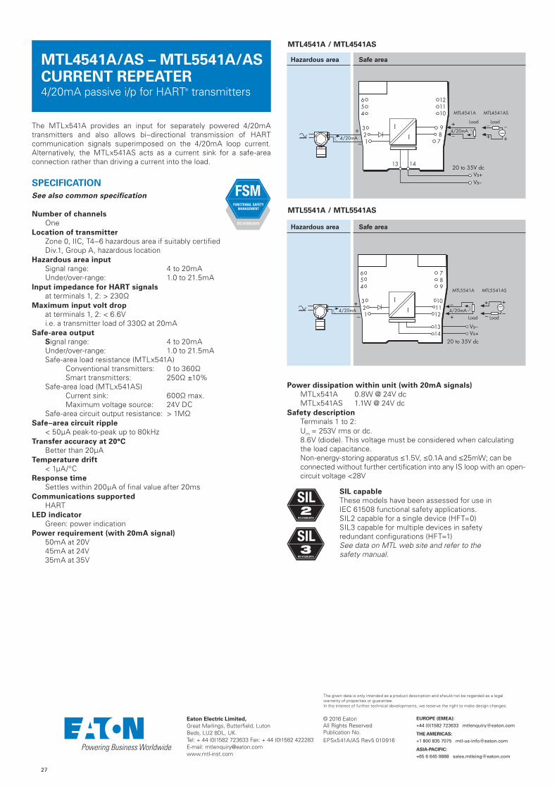
27
© 2016 EatonAll Rights ReservedPublication No.
Eaton Electric Limited, Great Marlings, Butterfield, LutonBeds, LU2 8DL, UK.Tel: + 44 (0)1582 723633 Fax: + 44 (0)1582 422283E-mail: [email protected]
EUROPE (EMEA):
+44 (0)1582 723633 [email protected]
THE AMERICAS:
+1 800 835 7075 [email protected]
ASIA-PACIFIC:
+65 6 645 9888 [email protected]
The given data is only intended as a product description and should not be regarded as a legal warranty of properties or guarantee. In the interest of further technical developments, we reserve the right to make design changes.
MTL4541A/AS – MTL5541A/AS CURRENT REPEATER4/20mA passive i/p for HART® transmitters
The MTLx541A provides an input for separately powered 4/20mA transmitters and also allows bi–directional transmission of HART communication signals superimposed on the 4/20mA loop current. Alternatively, the MTLx541AS acts as a current sink for a safe-area connection rather than driving a current into the load.
SPECIFICATIONSee also common specification
Number of channelsOne
Location of transmitterZone 0, IIC, T4–6 hazardous area if suitably certified Div.1, Group A, hazardous location
Hazardous area inputSignal range: 4 to 20mAUnder/over-range: 1.0 to 21.5mA
Input impedance for HART signalsat terminals 1, 2: > 230Ω
Maximum input volt dropat terminals 1, 2: < 6.6Vi.e. a transmitter load of 330Ω at 20mA
Safe-area output Signal range: 4 to 20mAUnder/over-range: 1.0 to 21.5mASafe-area load resistance (MTLx541A)
Conventional transmitters: 0 to 360ΩSmart transmitters: 250Ω ±10%
Safe-area load (MTLx541AS) Current sink: 600Ω max.Maximum voltage source: 24V DC
Safe-area circuit output resistance: > 1MΩSafe–area circuit ripple
< 50µA peak-to-peak up to 80kHzTransfer accuracy at 20°C
Better than 20µATemperature drift
< 1µA/°CResponse time
Settles within 200µA of final value after 20msCommunications supported
HARTLED indicator
Green: power indicationPower requirement (with 20mA signal)
50mA at 20V45mA at 24V35mA at 35V
Power dissipation within unit (with 20mA signals)MTLx541A 0.8W @ 24V dc MTLx541AS 1.1W @ 24V dc
Safety descriptionTerminals 1 to 2:Um = 253V rms or dc.8.6V (diode). This voltage must be considered when calculating the load capacitance.Non-energy-storing apparatus ≤1.5V, ≤0.1A and ≤25mW; can be connected without further certification into any IS loop with an open-circuit voltage <28V
MTL4541A / MTL4541AS
Hazardous area Safe area
–4/20mA
Load+
–
+
MTL4541A MTL4541AS
Load
+
––
+
Vs–Vs+
20 to 35V dc
4/20mA
654
321
I
I987
121110
13 14
MTL5541A / MTL5541AS
Hazardous area Safe area
Vs–Vs+
20 to 35V dc
–4/20mA
Load+
MTL5541A MTL5541AS
Load
+
––
+
–
+4/20mA
654
321
789
101112
1314
I
I
EPSx541A/AS Rev5 010916
FSM FUNCTIONAL SAFETY
MANAGEMENT
IEC 61508:2010
SIL capableThese models have been assessed for use in IEC 61508 functional safety applications. SIL2 capable for a single device (HFT=0) SIL3 capable for multiple devices in safety redundant configurations (HFT=1) See data on MTL web site and refer to the safety manual.
SIL2
IEC 61508:2010
SIL3
IEC 61508:2010

© 2016 EatonAll Rights ReservedPublication No.
Eaton Electric Limited, Great Marlings, Butterfield, LutonBeds, LU2 8DL, UK.Tel: + 44 (0)1582 723633 Fax: + 44 (0)1582 422283E-mail: [email protected]
EUROPE (EMEA):
+44 (0)1582 723633 [email protected]
THE AMERICAS:
+1 800 835 7075 [email protected]
ASIA-PACIFIC:
+65 6 645 9888 [email protected]
The given data is only intended as a product description and should not be regarded as a legal warranty of properties or guarantee. In the interest of further technical developments, we reserve the right to make design changes.
The MTL4541B provides a fully-floating dc supply for energising a conventional 2- or 3-wire 4/20mA transmitter which is located in a hazardous area, and repeats the current in another circuit to drive a safe-area load. For HART 2-wire transmitters, the unit allows bi-directional communications signals superimposed on the 4/20mA loop current.
SPECIFICATIONSee also common specification
Number of channelsOne
Location of transmitterZone 0, IIC, T4–6 hazardous area if suitably certifiedDiv. 1, Group A hazardous location
Safe-area output Signal range: 4 to 20mAUnder/over-range: 0 to 24mASafe-area load resistance: 0 to 360Ω @ 24mA
0 to 450Ω @ 20mASafe-area circuit output resistance: > 1MΩ
Safe-area circuit ripple<50µA peak-to-peak
Hazardous-area inputSignal range: 0 to 24mA (including over-range) Transmitter voltage: 16.5V at 20mA
Transfer accuracy at 20°CBetter than 15µA
Temperature drift< 0.8µA/°C
Response timeSettles to within 10% of final value within 50µs
Communications supportedHART (terminals 1 & 2 only)
Note: Safe area output referenced to PSU –ve
LED indicatorGreen: power indication
Maximum current consumption (with 20mA signal)51mA at 24V
Power dissipation within unit (with 20mA signal)0.7W at 24V
Safety descriptionTerminals 2 to 1 and 3:Vo=28V Io=93mA Po=651mW Um = 253V rms or dcTerminals 1 to 3:Simple apparatus ≤1.5V, ≤0.1A and ≤25mW; can be connected without further certification into any IS loop with an open-circuit voltage <28V
MTL4541B
Hazardous area Safe area
654
321
+
Vs–Vs+
20 to 35V dc
–4/20mA
Load
+–
4/20mA
I
I987
121110
13 14
MTL4541B REPEATER POWER SUPPLY 4/20mA, HART®, for 2- or 3-wire transmitters
EPS4541B Rev 3 021116
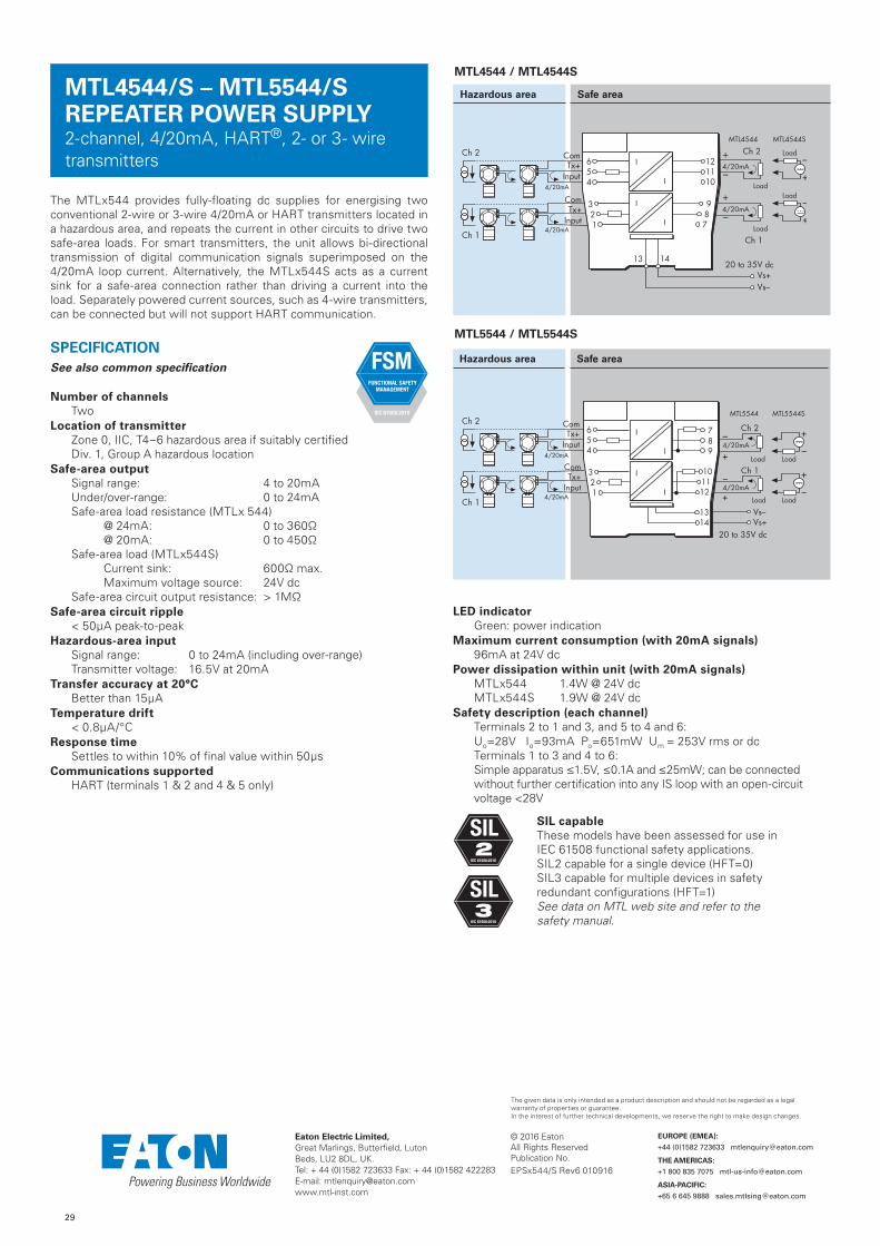
29
© 2016 EatonAll Rights ReservedPublication No.
Eaton Electric Limited, Great Marlings, Butterfield, LutonBeds, LU2 8DL, UK.Tel: + 44 (0)1582 723633 Fax: + 44 (0)1582 422283E-mail: [email protected]
EUROPE (EMEA):
+44 (0)1582 723633 [email protected]
THE AMERICAS:
+1 800 835 7075 [email protected]
ASIA-PACIFIC:
+65 6 645 9888 [email protected]
The given data is only intended as a product description and should not be regarded as a legal warranty of properties or guarantee. In the interest of further technical developments, we reserve the right to make design changes.
The MTLx544 provides fully-floating dc supplies for energising two conventional 2-wire or 3-wire 4/20mA or HART transmitters located in a hazardous area, and repeats the current in other circuits to drive two safe-area loads. For smart transmitters, the unit allows bi-directional transmission of digital communication signals superimposed on the 4/20mA loop current. Alternatively, the MTLx544S acts as a current sink for a safe-area connection rather than driving a current into the load. Separately powered current sources, such as 4-wire transmitters, can be connected but will not support HART communication.
SPECIFICATIONSee also common specification
Number of channelsTwo
Location of transmitterZone 0, IIC, T4–6 hazardous area if suitably certifiedDiv. 1, Group A hazardous location
Safe-area output Signal range: 4 to 20mAUnder/over-range: 0 to 24mASafe-area load resistance (MTLx 544)
@ 24mA: 0 to 360Ω @ 20mA: 0 to 450Ω
Safe-area load (MTLx544S) Current sink: 600Ω max.Maximum voltage source: 24V dc
Safe-area circuit output resistance: > 1MΩSafe-area circuit ripple
< 50µA peak-to-peakHazardous-area input
Signal range: 0 to 24mA (including over-range) Transmitter voltage: 16.5V at 20mA
Transfer accuracy at 20°CBetter than 15µA
Temperature drift< 0.8µA/°C
Response timeSettles to within 10% of final value within 50µs
Communications supportedHART (terminals 1 & 2 and 4 & 5 only)
MTL4544/S – MTL5544/S REPEATER POWER SUPPLY2-channel, 4/20mA, HART®, 2- or 3- wire transmitters
Hazardous area Safe area
Vs–Vs+
20 to 35V dc
–4/20mA
Load
+
–4/20mA
Load
+
Ch 2
Ch 1
MTL5544 MTL5544S
Load
+
–
Load
+
–
4/20mA
4/20mA
Ch 2
Ch 1
ComTx+
Input
ComTx+
Input
654
321
789
101112
1314
I
I
I
I
MTL4544 / MTL4544S
Hazardous area Safe area
+
–4/20mA
Load
Ch 2
Ch 1
MTL4544 MTL4544S
4/20mA
4/20mA
Load
+
–
Vs–Vs+
20 to 35V dc
Ch 2
Ch 1
+
–4/20mA
Load
Load
+
–
ComTx+
Input
ComTx+
Input
I
I
I
I
654
321
987
121110
13 14
MTL5544 / MTL5544S
LED indicatorGreen: power indication
Maximum current consumption (with 20mA signals)96mA at 24V dc
Power dissipation within unit (with 20mA signals)MTLx544 1.4W @ 24V dc MTLx544S 1.9W @ 24V dc
Safety description (each channel)Terminals 2 to 1 and 3, and 5 to 4 and 6:Uo=28V Io=93mA Po=651mW Um = 253V rms or dcTerminals 1 to 3 and 4 to 6:Simple apparatus ≤1.5V, ≤0.1A and ≤25mW; can be connected without further certification into any IS loop with an open-circuit voltage <28V
SIL capableThese models have been assessed for use in IEC 61508 functional safety applications. SIL2 capable for a single device (HFT=0) SIL3 capable for multiple devices in safety redundant configurations (HFT=1) See data on MTL web site and refer to the safety manual.
FSM FUNCTIONAL SAFETY
MANAGEMENT
IEC 61508:2010
EPSx544/S Rev6 010916
SIL2
IEC 61508:2010
SIL3
IEC 61508:2010

30
© 2016 EatonAll Rights ReservedPublication No.
Eaton Electric Limited, Great Marlings, Butterfield, LutonBeds, LU2 8DL, UK.Tel: + 44 (0)1582 723633 Fax: + 44 (0)1582 422283E-mail: [email protected]
EUROPE (EMEA):
+44 (0)1582 723633 [email protected]
THE AMERICAS:
+1 800 835 7075 [email protected]
ASIA-PACIFIC:
+65 6 645 9888 [email protected]
The given data is only intended as a product description and should not be regarded as a legal warranty of properties or guarantee. In the interest of further technical developments, we reserve the right to make design changes.
MTL4544A/AS – MTL5544A/AS CURRENT REPEATER 4/20mA passive i/p for HART® transmitters
The MTLx544A provides an input for separately powered 4/20mA transmitters and also allows bi–directional transmission of HART communication signals superimposed on the 4/20mA loop current, so that the transmitter can be interrogated either from the operator station or by a hand-held communicator (HHC). Alternatively, the MTLx544AS acts as a current sink for a safe-area connection rather than driving a current into the load.
SPECIFICATIONSee also common specification
Number of channelsTwo
Location of transmitterZone 0, IIC, T4–6 hazardous area if suitably certified Div.1, Group A, hazardous loc ation
Hazardous area inputSignal range: 4 to 20mAUnder/over-range: 1.0 to 21.5mA
Input impedance for HART signalsat terminals 1, 2 and 4, 5: > 230Ω
Maximum input volt dropat terminals 1, 2 and 4, 5: < 6.6Vi.e. a transmitter load of 330Ω at 20mA
Safe-area output Signal range: 4 to 20mAUnder/over-range: 1.0 to 21.5mASafe-area load resistance (MTL5544A)
Conventional transmitters: 0 to 360ΩSmart transmitters: 250Ω ±10%
Safe-area load (MTL5544AS) Current sink: 600Ω max.Maximum voltage source: 24V DC
Safe-area circuit output resistance: > 1MΩSafe–area circuit ripple
< 50µA peak-to-peak up to 80kHzTransfer accuracy at 20°C
Better than 20µATemperature drift
< 1µA/°CResponse time
Settles within 200µA of final value after 20msCommunications supported
HARTLED indicator
Green: power indicationPower requirement (with 20mA signal)
70mA at 24V85mA at 20V50mA at 35V
Power dissipation within unit (with 20mA signals)MTLx544A 1.5W @ 24V dc MTLx544AS 2.0W @ 24V dc
Safety descriptionTerminals 1 to 2 and 4 to 5:Um = 253V rms or dc.8.6V (diode). This voltage must be considered when calculating the load capacitance.Non-energy-storing apparatus ≤1.5V, ≤0.1A and ≤25mW; can be connected without further certification into any IS loop with an open-circuit voltage < 28V
Hazardous area Safe area
Vs–Vs+
20 to 35V dc
+
–
Ch 2
Ch 1 +
–
Ch 2
Ch 1
4/20mA
4/20mA
654
321
789
101112
1314
I
I
I
I
MTL5544A MTL5544AS
–4/20mA
Load+ Load
+
––
+
–4/20mA
Load+ Load
+
––
+
MTL4544A / MTL4544AS
Hazardous area Safe area
MTL5544A / MTL5544AS
EPSx544A/AS Rev5 010916
SIL capableThese models have been assessed for use in IEC 61508 functional safety applications. SIL2 capable for a single device (HFT=0) SIL3 capable for multiple devices in safety redundant configurations (HFT=1) See data on MTL web site and refer to the safety manual.
SIL2
IEC 61508:2010
SIL3
IEC 61508:2010
FSM FUNCTIONAL SAFETY
MANAGEMENT
IEC 61508:2010

© 2016 EatonAll Rights ReservedPublication No.
Eaton Electric Limited, Great Marlings, Butterfield, LutonBeds, LU2 8DL, UK.Tel: + 44 (0)1582 723633 Fax: + 44 (0)1582 422283E-mail: [email protected]
EUROPE (EMEA):
+44 (0)1582 723633 [email protected]
THE AMERICAS:
+1 800 835 7075 [email protected]
ASIA-PACIFIC:
+65 6 645 9888 [email protected]
The given data is only intended as a product description and should not be regarded as a legal warranty of properties or guarantee. In the interest of further technical developments, we reserve the right to make design changes.
MTL4544B REPEATER POWER SUPPLY2-channel, 4/20mA, HART®, 2- or 3-wiretransmitters
The MTL4544B provides fully-floating dc supplies for energising two conventional 2- or 3-wire 4/20mA or HART transmitters located in a hazardous area, and repeats the current in other circuits to drive two safe-area loads. For HART transmitters, the unit allows bi-directional transmission of digital communication signals superimposed on the 4/20mA signal so that the transmitter can be interrogated either from the operator station or by a hand-held communicator.
SPECIFICATIONSee also common specification
Number of channelsTwo
Location of transmitterZone 0, IIC, T4-6, hazardous area if suitably certifiedDiv 1, Group A, hazardous location
Safe-area output Signal range: 4 to 20mAUnder/over-range: 0 to 24mASafe-area load resistance: 0 to 360Ω @ 24mA
0 to 450Ω @ 20mASafe-area circuit output resistance: > 1MΩ
Safe-area circuit ripple< 50µA peak-to-peak
Hazardous-area inputSignal range: 0 to 24mA (including over-range) Transmitter voltage: 16.5V at 20mA
Transfer accuracy at 20°CBetter than 20µA
Temperature drift< 0.8µA/°C
Response timeSettles to within 10% of final value within 50µs
Communications supportedHART® (terminals 1 & 2 and 4 & 5 only)
Note: Safe area output referenced to PSU –ve
LED indicatorGreen: power indication
Maximum current consumption (with 20mA signals)96mA at 24V dc
Power dissipation within unit (with 20mA signals)1.4W at 24V dc
Safety description (each channel)Terminals 2 to 1 and 3, and 5 to 4 and 6:Vo=28V Io=93mA Po=651mW Um = 253V rms or dcTerminals 1 to 3 and 4 to 6:Simple apparatus ≤1.5V, ≤0.1A and ≤25mW; can be connected without further certification into any IS loop with an open-circuit voltage <28V
Hazardous area Safe area
+
–4/20mA
Load
Ch 2
Ch 1
Vs–Vs+
20 to 35V dc
+
–4/20mA
Load
+–
+–
4/20mA
4/20mA
Ch 2
Ch 1
I
I
I
654
321
987
121110
13 14
MTL4544B
EPS4544B Rev 3 021116

31
© 2016 EatonAll Rights ReservedPublication No.
Eaton Electric Limited, Great Marlings, Butterfield, LutonBeds, LU2 8DL, UK.Tel: + 44 (0)1582 723633 Fax: + 44 (0)1582 422283E-mail: [email protected]
EUROPE (EMEA):
+44 (0)1582 723633 [email protected]
THE AMERICAS:
+1 800 835 7075 [email protected]
ASIA-PACIFIC:
+65 6 645 9888 [email protected]
The given data is only intended as a product description and should not be regarded as a legal warranty of properties or guarantee. In the interest of further technical developments, we reserve the right to make design changes.
The MTLx544D provides a fully-floating dc supply for energising a conventional 2- or 3-wire 4/20mA transmitter located in a hazardous area, and repeats the current in other circuits to drive two safe-area loads. For HART 2-wire transmitters, the unit allows bi-directional transmission of digital communication signals superimposed on the 4/20mA loop current. Separately powered current sources, such as 4-wire transmitters, can be connected but will not support HART communication.
SPECIFICATIONSee also common specification
Number of channelsOne
Location of transmitterZone 0, IIC, T4–6 hazardous area if suitably certifiedDiv. 1, Group A hazardous location
Safe-area output Signal range: 4 to 20mAUnder/over-range: 0 to 24mASafe-area load resistance
@ 24mA: 0 to 360Ω @ 20mA: 0 to 450Ω
Safe-area circuit output resistance: > 1MΩSafe-area circuit ripple
< 50µA peak-to-peakHazardous-area input
Signal range: 0 to 24mA (including over-range) Transmitter voltage: 16.5V at 20mA
Transfer accuracy at 20°CBetter than 15µA
Temperature drift< 0.8µA/°C
Response timeSettles to within 10% of final value within 50µs
Communications supportedHART (terminals 1 & 2, output Ch 1 only)
MTL4544D – MTL5544D REPEATER POWER SUPPLYsingle channel, 4/20mA, HART® for 2- or 3-wire transmitters, two outputs
Hazardous area Safe area
Vs–Vs+
20 to 35V dc
Ch 2
Ch 1
–4/20mA
Load+
–4/20mA
Load+4/20mA
654
321
789
101112
1314
ComTx+
Input
I
I
I
MTL4544D
Hazardous area Safe area
+
–4/20mA
Load
Ch 2
Ch 1
Vs–Vs+
20 to 35V dc
+
–4/20mA
Load
I
I
I
654
321
987
121110
13 14
4/20mA
ComTx+
Input
MTL5544D
LED indicatorGreen: power indication
Maximum current consumption (with 20mA signals)96mA at 24V dc
Power dissipation within unit (with 20mA signals)1.4W @ 24V dc
Safety descriptionTerminals 2 to 1 and 3:Uo=28V Io=93mA Po=651mW Um = 253V rms or dcTerminals 1 to 3:Simple apparatus ≤1.5V, ≤0.1A and ≤25mW; can be connected without further certification into any IS loop with an open-circuit voltage <28V
SIL capableThese models have been assessed for use in IEC 61508 functional safety applications. SIL2 capable for a single device (HFT=0) SIL3 capable for multiple devices in safety redundant configurations (HFT=1) See data on MTL web site and refer to the safety manual.
FSM FUNCTIONAL SAFETY
MANAGEMENT
IEC 61508:2010
EPSx544D Rev7 010916
SIL2
IEC 61508:2010
SIL3
IEC 61508:2010

32
© 2016 EatonAll Rights ReservedPublication No.
Eaton Electric Limited, Great Marlings, Butterfield, LutonBeds, LU2 8DL, UK.Tel: + 44 (0)1582 723633 Fax: + 44 (0)1582 422283E-mail: [email protected]
EUROPE (EMEA):
+44 (0)1582 723633 [email protected]
THE AMERICAS:
+1 800 835 7075 [email protected]
ASIA-PACIFIC:
+65 6 645 9888 [email protected]
The given data is only intended as a product description and should not be regarded as a legal warranty of properties or guarantee. In the interest of further technical developments, we reserve the right to make design changes.
MTL4546/C/Y – MTL5546/Y ISOLATING DRIVER for 4–20mA HART® valve positioners with line fault detection
The MTLx546 accepts a 4/20mA floating signal from a safe-area controller to drive a current/pressure converter (or any other load up to 800Ω) in a hazardous area. For HART valve positioners, the module also permits bi-directional transmission of digital communication signals. Process controllers with a readback facility can detect open or short circuits in the field wiring: if these occur, the current taken into the terminals drops to a preset level. The MTL4546C and the MTLx546Y are very similar to the MTLx546 except that they provide open circuit detection only (i.e. no short-circuit detection).
SPECIFICATIONSee also common specification
Number of channelsOne
Location of I/P converterZone 0, IIC, T4–6 hazardous area if suitably certifiedDiv. 1, Group A, hazardous location
Working range4 to 20mA
Digital signal bandwidth500Hz to 10kHz
Maximum load resistance800Ω (16V at 20mA)
Minimum load resistance90Ω (short-circuit detection at < 50Ω)
Output resistance> 1MΩ
Under/over range capabilityUnder range = 1mAOver range = 24mA (load ≤ 520Ω)
Input and output circuit ripple< 40µA peak-to-peak
Transfer accuracy at 20°CBetter than 20µA
Temperature drift< 1.0µA/°C
Input characteristics
Field wiring state MTLx546 MTL4546C MTLx546Y
Normal < 6.0V < 6.0V < 6.0V
Open-circuit < 0.9mA < 0.9mA < 0.5mA
Short-circuit < 0.9mA N.A. N.A.
Response timeSettles within 200µA of final value within 100ms
Communications supportedHART
LED indicatorGreen: power indication
Maximum current consumption (with 20mA signals into 250Ω load)35mA at 24V dc
Power dissipation within unit (with 20mA signals into 250Ω load)0.8W at 24V
Safety descriptionUo=28V Io=93mA Po=651mW Um = 253V rms or dc
SIL capableThese models have been assessed for use in IEC 61508 functional safety applications. SIL2 capable for a single device (HFT=0) SIL3 capable for multiple devices in safety redundant configurations (HFT=1) See data on MTL web site and refer to the safety manual.
Hazardous area Safe area
MTL4546 / MTL4546C / MTL4546Y
Hazardous area Safe area
–
+4/20mA
PI
4/20mA+
–
Vs–Vs+
20 to 35V dc
654
321
I
I
987
121110
13 14
MTL5546 / MTL5546Y
FSM FUNCTIONAL SAFETY
MANAGEMENT
IEC 61508:2010
EPSx546/C/Y Rev6 010916
SIL2
IEC 61508:2010
SIL3
IEC 61508:2010
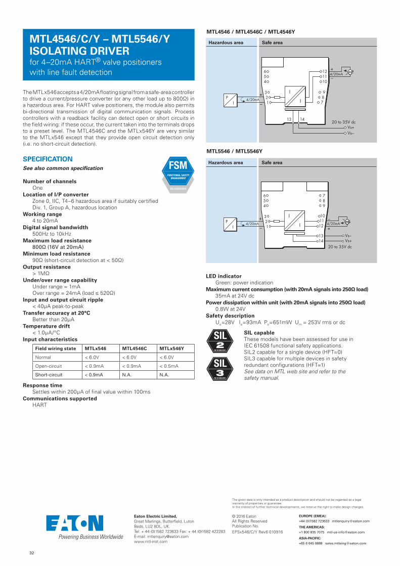
32
© 2016 EatonAll Rights ReservedPublication No.
Eaton Electric Limited, Great Marlings, Butterfield, LutonBeds, LU2 8DL, UK.Tel: + 44 (0)1582 723633 Fax: + 44 (0)1582 422283E-mail: [email protected]
EUROPE (EMEA):
+44 (0)1582 723633 [email protected]
THE AMERICAS:
+1 800 835 7075 [email protected]
ASIA-PACIFIC:
+65 6 645 9888 [email protected]
The given data is only intended as a product description and should not be regarded as a legal warranty of properties or guarantee. In the interest of further technical developments, we reserve the right to make design changes.
MTL4546/C/Y – MTL5546/Y ISOLATING DRIVER for 4–20mA HART® valve positioners with line fault detection
The MTLx546 accepts a 4/20mA floating signal from a safe-area controller to drive a current/pressure converter (or any other load up to 800Ω) in a hazardous area. For HART valve positioners, the module also permits bi-directional transmission of digital communication signals. Process controllers with a readback facility can detect open or short circuits in the field wiring: if these occur, the current taken into the terminals drops to a preset level. The MTL4546C and the MTLx546Y are very similar to the MTLx546 except that they provide open circuit detection only (i.e. no short-circuit detection).
SPECIFICATIONSee also common specification
Number of channelsOne
Location of I/P converterZone 0, IIC, T4–6 hazardous area if suitably certifiedDiv. 1, Group A, hazardous location
Working range4 to 20mA
Digital signal bandwidth500Hz to 10kHz
Maximum load resistance800Ω (16V at 20mA)
Minimum load resistance90Ω (short-circuit detection at < 50Ω)
Output resistance> 1MΩ
Under/over range capabilityUnder range = 1mAOver range = 24mA (load ≤ 520Ω)
Input and output circuit ripple< 40µA peak-to-peak
Transfer accuracy at 20°CBetter than 20µA
Temperature drift< 1.0µA/°C
Input characteristics
Field wiring state MTLx546 MTL4546C MTLx546Y
Normal < 6.0V < 6.0V < 6.0V
Open-circuit < 0.9mA < 0.9mA < 0.5mA
Short-circuit < 0.9mA N.A. N.A.
Response timeSettles within 200µA of final value within 100ms
Communications supportedHART
LED indicatorGreen: power indication
Maximum current consumption (with 20mA signals into 250Ω load)35mA at 24V dc
Power dissipation within unit (with 20mA signals into 250Ω load)0.8W at 24V
Safety descriptionUo=28V Io=93mA Po=651mW Um = 253V rms or dc
SIL capableThese models have been assessed for use in IEC 61508 functional safety applications. SIL2 capable for a single device (HFT=0) SIL3 capable for multiple devices in safety redundant configurations (HFT=1) See data on MTL web site and refer to the safety manual.
Hazardous area Safe area
MTL4546 / MTL4546C / MTL4546Y
Hazardous area Safe area
–
+4/20mA
PI
4/20mA+
–
Vs–Vs+
20 to 35V dc
654
321
I
I
987
121110
13 14
MTL5546 / MTL5546Y
FSM FUNCTIONAL SAFETY
MANAGEMENT
IEC 61508:2010
EPSx546/C/Y Rev6 010916
SIL2
IEC 61508:2010
SIL3
IEC 61508:2010

34
© 2016 EatonAll Rights ReservedPublication No.
Eaton Electric Limited, Great Marlings, Butterfield, LutonBeds, LU2 8DL, UK.Tel: + 44 (0)1582 723633 Fax: + 44 (0)1582 422283E-mail: [email protected]
EUROPE (EMEA):
+44 (0)1582 723633 [email protected]
THE AMERICAS:
+1 800 835 7075 [email protected]
ASIA-PACIFIC:
+65 6 645 9888 [email protected]
The given data is only intended as a product description and should not be regarded as a legal warranty of properties or guarantee. In the interest of further technical developments, we reserve the right to make design changes.
MTL4549/C/Y - MTL5549/YISOLATING DRIVER two-channel, for 4–20mA, HART® valve positioners with line fault detection
The MTLx549 accepts 4/20mA floating signals from safe-area controllers to drive 2 current/pressure converters (or any other load up to 800Ω) in a hazardous area. For HART valve positioners, the module also permits bi-directional transmission of digital communication signals. Process controllers with a readback facility can detect open or short circuits in the field wiring: if these occur, the current taken into the terminals drops to a preset level. The MTL4549C and MTLx549Y are very similar to the MTLx549 except that they provide open circuit detection only (i.e. no short-circuit detection).
SPECIFICATIONSee also common specification
Number of channelsTwo
Location of I/P converterZone 0, IIC, T4–6 hazardous area if suitably certifiedDiv. 1, Group A, hazardous location
Working range4 to 20mA
Digital signal bandwidth500Hz to 10kHz
Maximum load resistance800Ω (16V at 20mA)
Minimum load resistance90Ω (short-circuit detection at < 50Ω)
Output resistance> 1MΩ
Under/over range capabilityUnder range = 1mAOver range = 24mA (load ≤ 520Ω)
Input and output circuit ripple<40µA peak-to-peak
Communications supportedHART
Transfer accuracy at 20°CBetter than 20µA
Temperature drift< 1.0µA/°C
Input characteristics
Field wiring state MTL4549 MTL4549C MTL4549Y
Normal < 6.0V < 6.0V < 6.0V
Open-circuit < 0.9mA < 0.9mA < 0.5mA
Short-circuit < 0.9mA N.A. N.A.
Response timeSettles within 200µA of final value within 100ms
Hazardous area Safe area
MTL4549 / MTL4549C / MTL4549Y
Hazardous area Safe area
4/20mAP
I
+
–
PI
+
–
+4/20mA
Ch 2
Ch 1
Ch 2
Ch 1–4/20mA
4/20mA
Vs–Vs+
20 to 35V dc
+
–
654
321
I
I
I
I
987
121110
13 14
MTL5549 / MTL5549Y
LED indicatorGreen: power indication
Maximum current consumption (with 20mA signals into 250Ω load)70mA at 24V dc
Power dissipation within unit (with 20mA signals into 250Ω load)1.6W at 24V
Safety description (each channel)Uo=28V Io=93mA Po=0.65W Um = 253V rms or dc
SIL capableThese models have been assessed for use in IEC 61508 functional safety applications. SIL2 capable for a single device (HFT=0) SIL3 capable for multiple devices in safety redundant configurations (HFT=1) See data on MTL web site and refer to the safety manual.
FSM FUNCTIONAL SAFETY
MANAGEMENT
IEC 61508:2010
EPSx549/C/Y Rev6 010916
SIL2
IEC 61508:2010
SIL3
IEC 61508:2010

35
© 2017 EatonAll Rights ReservedPublication No.
Eaton Electric Limited, Great Marlings, Butterfield, LutonBeds, LU2 8DL, UK.Tel: + 44 (0)1582 723633 Fax: + 44 (0)1582 422283E-mail: [email protected]
EUROPE (EMEA):
+44 (0)1582 723633 [email protected]
THE AMERICAS:
+1 800 835 7075 [email protected]
ASIA-PACIFIC:
+65 6 645 9888 [email protected]
The given data is only intended as a product description and should not be regarded as a legal warranty of properties or guarantee. In the interest of further technical developments, we reserve the right to make design changes.
Hazardous area Safe area
–
–
++
–
+
–
Ch 2
Ch 1
Ch 2
Ch 1
+654
321
I
I
I
IFire
detectors 987
121110
13 14
MTL4561 – MTL5561 FIRE AND SMOKE DETECTOR INTERFACE 2-channel
The MTLx561 is a loop-powered 2–channel interface for use with conventional fire and smoke detectors located in hazardous areas. In operation, the triggering of a detector causes a corresponding change in the safe–area current. The unit features reverse input polarity protection.
SPECIFICATIONSee also common specification
Number of channelsTwo, fully floating, loop powered
Location of fire and smoke detectorsZone 0, IIC, T4–6 hazardous area if suitably certifiedDiv. 1, Group A, hazardous area
Input voltage6 to 30V dc
Current range1 to 40mA, nominal
Quiescent safe–area current at 20°C(hazardous–area terminals open circuit)< 400µA at Vin = 24V per channel
Integral input polarity protectionInput circuit protected against reverse polarity
Minimum output voltage Vout at 20°CFor Vin ≤ 25V: Vout = Vin – (0.38 x current in mA) – 2VFor Vin > 25V: Vout = 22.5V – (0.35 x current in mA)
Maximum output voltage28V from 300Ω
Transfer accuracy at 20°CBetter than 400µA
Temperature drift< 4µA/°C ( 0°C to 60°C)< 15µA/°C (–20°C to 0°C)
Response time to step inputSettles to within 5% of final value within 1.5ms
Power dissipation within unit0.7W maximum at 24V with 40mA signal (each channel)0.9W maximum at 30V with 40mA signal (each channel)
Safety description for each channel Uo=28V Io=93mA Po=0.65W Um = 253V rms or dc
MTL5561
MTL4561
Hazardous area Safe area
FSM FUNCTIONAL SAFETY
MANAGEMENT
IEC 61508:2010
SIL capableThese models have been assessed for use in IEC 61508 functional safety applications. SIL2 capable for a single device (HFT=0) SIL3 capable for multiple devices in safety redundant configurations (HFT=1) See data on MTL web site and refer to the safety manual.
EPSx561 Rev7 010916
SIL2
IEC 61508:2010
SIL3
IEC 61508:2010
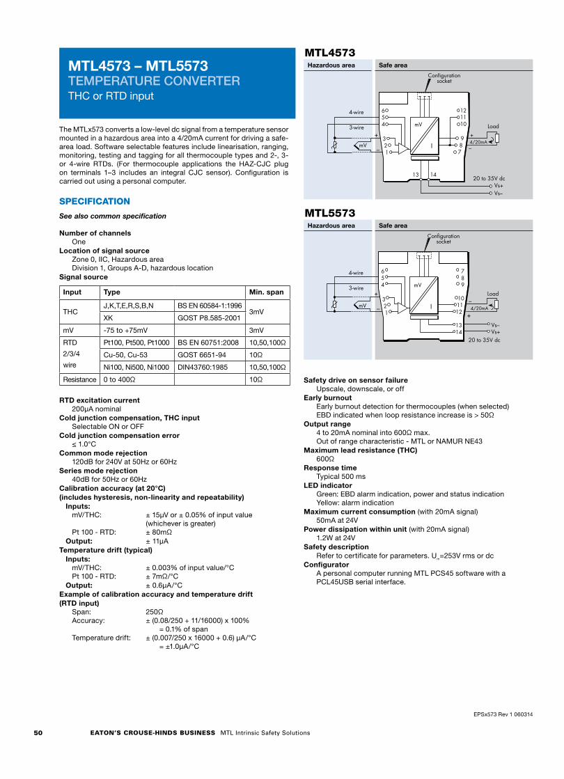
EATON’S CROUSE-HINDS BUSINESS MTL Intrinsic Safety Solutions50
The MTLx573 converts a low-level dc signal from a temperature sensor mounted in a hazardous area into a 4/20mA current for driving a safe-area load. Software selectable features include linearisation, ranging, monitoring, testing and tagging for all thermocouple types and 2-, 3- or 4-wire RTDs. (For thermocouple applications the HAZ-CJC plug on terminals 1–3 includes an integral CJC sensor). Configuration is carried out using a personal computer.
SPECIFICATION
See also common specification
Number of channelsOne
Location of signal sourceZone 0, IIC, Hazardous areaDivision 1, Groups A-D, hazardous location
Signal source
Input Type Min. span
THCJ,K,T,E,R,S,B,N BS EN 60584-1:1996
3mVXK GOST P8.585-2001
mV -75 to +75mV 3mV
RTD
2/3/4
wire
Pt100, Pt500, Pt1000 BS EN 60751:2008 10,50,100Ω
Cu-50, Cu-53 GOST 6651-94 10Ω
Ni100, Ni500, Ni1000 DIN43760:1985 10,50,100Ω
Resistance 0 to 400Ω 10Ω
RTD excitation current200µA nominal
Cold junction compensation, THC inputSelectable ON or OFF
Cold junction compensation error≤ 1.0°C
Common mode rejection120dB for 240V at 50Hz or 60Hz
Series mode rejection40dB for 50Hz or 60Hz
Calibration accuracy (at 20°C)(includes hysteresis, non-linearity and repeatability) Inputs:
mV/THC: ± 15µV or ± 0.05% of input value (whichever is greater)Pt 100 - RTD: ± 80mΩ
Output: ± 11µATemperature drift (typical) Inputs:
mV/THC: ± 0.003% of input value/°CPt 100 - RTD: ± 7mΩ/°C
Output: ± 0.6µA/°CExample of calibration accuracy and temperature drift(RTD input)
Span: 250ΩAccuracy: ± (0.08/250 + 11/16000) x 100% = 0.1% of spanTemperature drift: ± (0.007/250 x 16000 + 0.6) µA/°C = ±1.0µA/°C
Safety drive on sensor failureUpscale, downscale, or off
Early burnoutEarly burnout detection for thermocouples (when selected) EBD indicated when loop resistance increase is > 50Ω
Output range4 to 20mA nominal into 600Ω max.Out of range characteristic - MTL or NAMUR NE43
Maximum lead resistance (THC)600Ω
Response timeTypical 500 ms
LED indicatorGreen: EBD alarm indication, power and status indicationYellow: alarm indication
Maximum current consumption (with 20mA signal)50mA at 24V
Power dissipation within unit (with 20mA signal)1.2W at 24V
Safety descriptionRefer to certificate for parameters. Um=253V rms or dc
ConfiguratorA personal computer running MTL PCS45 software with a PCL45USB serial interface.
MTL4573 – MTL5573 TEMPERATURE CONVERTERTHC or RTD input
MTL4573Hazardous area Safe area
–
+
mV
4-wire
3-wire
Configurationsocket
Vs–Vs+
20 to 35V dc
Load
4/20mA–
+
654
321
I
mV
987
121110
13 14
MTL5573Hazardous area Safe area
Vs–Vs+
20 to 35V dc
–
+
mV
4-wire
3-wire
Configurationsocket
Load
+4/20mA
–
654
321
789
101112
1314
I
mV
EPSx573 Rev 1 060314

37
© 2016 EatonAll Rights ReservedPublication No.
Eaton Electric Limited, Great Marlings, Butterfield, LutonBeds, LU2 8DL, UK.Tel: + 44 (0)1582 723633 Fax: + 44 (0)1582 422283E-mail: [email protected]
EUROPE (EMEA):
+44 (0)1582 723633 [email protected]
THE AMERICAS:
+1 800 835 7075 [email protected]
ASIA-PACIFIC:
+65 6 645 9888 [email protected]
The given data is only intended as a product description and should not be regarded as a legal warranty of properties or guarantee. In the interest of further technical developments, we reserve the right to make design changes.
The MTLx575 converts a low-level dc signal from a temperature sensor mounted in a hazardous area into a 4/20mA current for driving a safe-area load. Software selectable features include linearisation, ranging, monitoring, testing and tagging for all thermocouple types and 2-, 3- or 4-wire RTDs. (For thermocouple applications the HAZ-CJC plug on terminals 1–3 includes an integral CJC sensor). Configuration is carried out using a personal computer. A single alarm output is provided and may be configured for process alarm or to provide notice of early thermocouple failure.
SPECIFICATIONSee also common specification
Number of channelsOne
Signal sourceTHC types J, K, T, E, R, S, B or N to BS 60584 and XKmV inputRTDs 2/3/4-wire platinum to BS 60751
Pt 100, Pt 500, Pt 1000Cu-50 & Cu-53Ni 100/500/1000 DIN 43760
Location of signal sourceZone 0, IIC, T4-6 hazardous areaDivision 1, Group A, hazardous location
Input signal range–75 to +75mV, or 0 to 400Ω (0 to 1000Ω Pt & Ni sensors)
Input signal span3 to 150mV, or 10 to 400Ω (10 to 1000Ω Pt & Ni sensors)
RTD excitation current200µA nominal
Cold junction compensationAutomatic or selectable
Cold junction compensation error≤ 1.0°C
Common mode rejection120dB for 240V at 50Hz or 60Hz (500ms response)
Series mode rejection40dB for 50Hz or 60Hz
Calibration accuracy (at 20°C)(includes hysteresis, non-linearity and repeatability)
Inputs: (500ms response)mV/THC: ± 15µV or ± 0.05% of input value
(whichever is greater)RTD: ± 80mΩ
Output: ± 11µATemperature drift (typical)
Inputs:mV/THC: ± 0.003% of input value/°CRTD: ± 7mΩ/°C
Output: ± 0.6µA/°CExample of calibration accuracy and temperature drift(RTD input - 500ms response)
Span: 250ΩAccuracy: ± (0.08/250 + 11/16000) x 100%
= 0.1% of spanTemperature drift: ± (0.007/250 x 16000 + 0.6) µA/°C
= ±1.0µA/°CSafety drive on sensor failure
Upscale, downscale, or off
Early burnoutEarly burnout detection for thermocouples (when selected) Alarm trips when loop resistance increase is > 50Ω
Output range4 to 20mA nominal into 600Ω max.
Alarm output (configurable)Relay ON in alarm, 250mA @ 35V max
Maximum lead resistance (THC)600Ω
Response timeConfigurable - 500 ms default(Accuracy at 100/200ms - contact MTL)
LED indicatorGreen: power and status indicationYellow: alarm indication, on when contacts are closed
Maximum current consumption (with 20mA signal)50mA at 24V
Power dissipation within unit (with 20mA signal)1.2W at 24V
Safety descriptionRefer to certificate for parameters. Um=253V rms or dc
ConfiguratorA personal computer running MTL PCS45 software with a PCL45USB serial interface.
MTL4575 – MTL5575 TEMPERATURE CONVERTERTHC or RTD input + Alarm
MTL4575
Hazardous area Safe area
–
+
mV
4-wire
3-wire
Configurationsocket
Vs–Vs+
20 to 35V dc
Load
Alarm
4/20mA–
+
654
321
I
mV
987
121110
13 14
MTL5575
Hazardous area Safe area
EPSx575 Rev4 010916

40
© 2016 EatonAll Rights ReservedPublication No.
Eaton Electric Limited, Great Marlings, Butterfield, LutonBeds, LU2 8DL, UK.Tel: + 44 (0)1582 723633 Fax: + 44 (0)1582 422283E-mail: [email protected]
EUROPE (EMEA):
+44 (0)1582 723633 [email protected]
THE AMERICAS:
+1 800 835 7075 [email protected]
ASIA-PACIFIC:
+65 6 645 9888 [email protected]
The given data is only intended as a product description and should not be regarded as a legal warranty of properties or guarantee. In the interest of further technical developments, we reserve the right to make design changes.
MTL4581 – MTL5581MILLIVOLT/THERMOCOUPLE ISOLATORfor low-level signals
The MTLx581 takes a low-level dc signal from a voltage source in a hazardous area, isolates it, and passes it to a receiving instrument located in the safe area. The module is intended for use with thermocouples utilising external cold-junction compensation. A switch enables or disables the safety drive in the event of thermocouple burnout or cable breakage; a second switch permits the selection of upscale or downscale operation as appropriate.
SPECIFICATIONSee also common specification
Number of channelsOne
Signal sourceAny dc millivolt source
Location of millivolt sourceZone 0, IIC, T4–T6 hazardous area if suitably certifiedDiv. 1, Group A, hazardous location
Input and output signal range0 to ± 50mV, overrange to ± 55mVMaximum lead resistance 600Ω
Output resistance60Ω nominal
Transfer accuracy@20°CLinearity and repeatability < 0.05% of reading or ± 5μV,whichever is the greater
Temperature drift< 2μV/°C, maximum
Response timeSettles to within 10% of final value within 150μs
Frequency responsedc to 4kHz nominal
Safety drive on THC burnoutTwo switches enable or disable the safety drive and selectupscale or downscale operation
MTL5581
MTL4581
Hazardous area Safe area
–
+Output
Vs–Vs+
20 to 35V dc
+
–
654
321
mV
mV
987
121110
13 14
mV
* Use compensating cable withthermocouple inputs
Hazardous area Safe area
–
Vs–Vs+
20 to 35V dc
+Output*
+
–
* Use compensating cable withthermocouple inputs
654
321
789
101112
1314
mV
mVmVmV
LED indicatorGreen: power indication
Power requirement, Vs30mA max, 20V dc to 35V dc
Power dissipation within unit0.7W typical at 24V0.91W at 35V
Safety descriptionTerminals 1 to 2Non-energy-storing apparatus ≤ 1.5V, ≤ 0.1A and ≤ 25mW; canbe connected without further certification into any IS loop with anopen-circuit voltage <28V
EPSx581 Rev4 010916

15
© 2017 EatonAll Rights ReservedPublication No.
Eaton Electric Limited, Great Marlings, Butterfield, LutonBeds, LU2 8DL, UK.Tel: + 44 (0)1582 723633 Fax: + 44 (0)1582 422283E-mail: [email protected]
EUROPE (EMEA):
+44 (0)1582 723633 [email protected]
THE AMERICAS:
+1 800 835 7075 [email protected]
ASIA-PACIFIC:
+65 6 645 9888 [email protected]
The given data is only intended as a product description and should not be regarded as a legal warranty of properties or guarantee. In the interest of further technical developments, we reserve the right to make design changes.
MTL5522 SOLENOID/ALARM DRIVERloop-powered, IIB
The MTL5522 is a loop-powered module which enables a device located in the hazardous area to be controlled from the safe area. The MTL5522 can drive a certified intrinsically safe low-power load, as well as non-energy-storing simple apparatus such as an LED. The unit's input/output isolation allows the control switch to be connected into either side of the 24V dc supply circuit.
SPECIFICATIONSee also common specification
Number of channelsOne
Location of loadZone 0, IIB, T4–6 hazardous area if suitably certifiedDiv. 1, Group C hazardous location
Minimum output voltage Equivalent output circuit
70Output current (mA)
Outputvoltage(V)
22.2
10.7 22.2V minimum
158Ω maximum
Current limit: 70mA
Input voltage20 to 35V dc
Hazardous-area outputMinimum output voltage: 10.7V at 70mAMaximum output voltage: 24V from 158ΩCurrent limit: 70mA minimum
Output ripple< 0.5% of maximum output, peak to peak
Response timeOutput within 10% of final value within 100ms
LED indicatorYellow: output status, on when output active
Maximum current consumption 125mA (typ.) at 24V
Power dissipation within unit1.4W at 24V
Safety descriptionUo=25V Io=166mA Po=1.04W Um = 253V rms or dc
SIL capableThese models have been assessed for use in IEC 61508 functional safety applications. SIL3 capable for a single device (HFT=0) when the required function is to de-energise the output. SIL1 capable for a single device (HFT=0) when the required function is to energise the output.See data on MTL web site and refer to the safety manual.
Hazardous area Safe area
654
321
789
101112
1314
Solenoid, alarm or other IS device
20 – 35Vdc–+
+
–
MTL5522
FSM FUNCTIONAL SAFETY
MANAGEMENT
IEC 61508:2010
EPSx522 Rev8 040517
SIL3
IEC 61508:2010
SIL1
IEC 61508:2010

25
© 2016 EatonAll Rights ReservedPublication No.
Eaton Electric Limited, Great Marlings, Butterfield, LutonBeds, LU2 8DL, UK.Tel: + 44 (0)1582 723633 Fax: + 44 (0)1582 422283E-mail: [email protected]
EUROPE (EMEA):
+44 (0)1582 723633 [email protected]
THE AMERICAS:
+1 800 835 7075 [email protected]
ASIA-PACIFIC:
+65 6 645 9888 [email protected]
The given data is only intended as a product description and should not be regarded as a legal warranty of properties or guarantee. In the interest of further technical developments, we reserve the right to make design changes.
The MTL5533 repeats signals from vibration sensors in a hazardous area, providing outputs for a monitoring system in the safe area. The interface is compatible with 3-wire eddy-current probes and accelerometers or 2-wire current sensors, the selection is made by switches on the side of the module.
SPECIFICATIONSee also common specification
Number of channelsTwo
Sensor type2- or 3-wire vibration transducer
Location of signal sourceZone 0, IIC, T4–6 hazardous area if suitably certifiedDiv. 1, Group A hazardous location
Hazardous-area input Input impedance(terminals 2 & 3, 5 & 6): 10kΩ
Transducer supply voltage, 3-wire (terminals 3 & 1 and 6 & 4)
Output current –20mA
Outputvoltage
–24V
0
350Ω
–17V
Transducer supply current, 2-wire3.3mA (nom.) for 2-wire sensors, user selectable by switch
Signal rangeMinimum –20V, maximum –0.5V
DC transfer accuracy at 20°C<±50mV
AC transfer accuracy at 20°C0Hz to 1kHz: ±1%1kHz to 10kHz: –5% to +1%10kHz to 20kHz: –10% to +1%
Temperature coefficient±50ppm/°C (10 to 65°C)±100ppm/°C (–20 to 10°C)
Voltage bandwidth –3dB at 47kHz (typical)
Phase response<14µs, equivalent to:–1° at 200Hz–3° at 600Hz–5° at 1kHz–50° at 10kHz–100° at 20kHz
Safe-area output impedance <20Ω
LED indicatorGreen: power indication
Supply voltage20 to 35V dc
Maximum current consumption (10mA transducer load/ch)130mA at 24V
Maximum power dissipation within unit 2.7W
Safety descriptionTerminals 3 to 1 and 6 to 4Uo=26.6V Io=94mA Po=0.66W Um = 253V rms or dcTerminals 3 to 2 and 6 to 5Non-energy-storing apparatus ≤1.5V, ≤0.1A and ≤25mW
Note -Refer to the Instruction Manual for recommendations on mounting of these modules.
A minimum spacing of 10mm must be applied between these and any other modules on the DIN-rail.
Maximum ambient temperature with this spacing is 50°C.
MTL5533VIBRATION TRANSDUCER INTERFACE2-channel
MTL5533
Hazardous area Safe area
Vibrationtransducer
Vibrationtransducer
Vibrationtransducer
Vibrationtransducer
COMSIGV–
COMSIGV–
Vs–Vs+
20 to 35V dc
–ve
0VMonitor
3-wire
2
1
3-wire
2-wire
5
4
2-wire
Monitor–ve
0V
3
6
Ch 1
Ch 2
Ch 1
Ch 2654
321
789
101112
1314
EPSx533 Rev6 010916

41
© 2016 EatonAll Rights ReservedPublication No.
Eaton Electric Limited, Great Marlings, Butterfield, LutonBeds, LU2 8DL, UK.Tel: + 44 (0)1582 723633 Fax: + 44 (0)1582 422283E-mail: [email protected]
EUROPE (EMEA):
+44 (0)1582 723633 [email protected]
THE AMERICAS:
+1 800 835 7075 [email protected]
ASIA-PACIFIC:
+65 6 645 9888 [email protected]
The given data is only intended as a product description and should not be regarded as a legal warranty of properties or guarantee. In the interest of further technical developments, we reserve the right to make design changes.
MTL5582RESISTANCE ISOLATORto repeat RTD signals
The MTL5582 connects to a 2-, 3-, or 4-wire resistance temperature device (RTD) or other resistance located in a hazardous area, isolates it and repeats the resistance to a monitoring system in the safe area. The module is intended typically (but not exclusively) for use with Pt100 3-wire RTDs. Switches enable selection of 2-, 3-, or 4-wire RTD connection. The MTL5582 should be considered as an alternative, non-configurable MTL5575, for use in RTD applications where a resistance input is preferred or needed instead of 4/20mA. The design is notable for its ease of use and repeatability. The number of wires which can be connected on the safe-area side of the unit is independent of the number of wires which can be connected on the hazardous-area side. The module drives upscale in the case of open circuit detection. Note that this module is not suitable for use with measurement systems where the resistance input channels are multiplexed.
SPECIFICATIONSee also common specification
Number of channelsOne
Location of RTDZone 0, IIC, T4 hazardous areaDiv. 1, Group A, hazardous location
Resistance source2-, 3-, or 4-wire* RTDs to BS 1904/DIN 43760 (100Ω at 0°C)*user selectable by switches (factory set for 3-wire)
Resistance range10Ω to 400Ω
RTD excitation current200μA nominal
Output configuration2, 3 or 4 wires (independent of mode selected for hazardous areaterminals)
Output range10Ω to 400Ω (from a 100μA to 5mA source)
Temperature drift±10mΩ/C° typical (0.01%/°C @ 100Ω)
Response timeTo within 4% of final value within 1s Not suitable for muliplexed input cards
Safety drive on open-circuit sensorUpscale to 420Ω nominal
Transfer accuracy@20°C<0.15Ω at excitation current 1 - 5mA <0.25Ω at excitation current 0.5 - 1mA
LED indicatorGreen: power indication
Power requirements, Vs33mA at 24V35mA at 20V28mA at 35V
Maximum power dissipation within unit0.8W at 24V1.0W at 35V
Safety descriptionTerminals 1 and 3Uo = 1.2V Io = 4mA Po = 1.2mW Um = 253V rms or dcNon-energy-storing apparatus ≤ 1.5V, ≤ 0.1A, ≤ 25mW; canbe connected without further certification into any IS loop withan open circuit voltage < 5V.Terminals 1 and 3 and 4 and 5Uo = 6.6V Io = 42mA Po = 69mW
NOTE: The MTL5582 is due to be superceeded by the MTL5582B during Q3 2016.
MTL5582
Hazardous area Safe area
EPS5582 Rev5 010916
FSM FUNCTIONAL SAFETY
MANAGEMENT
IEC 61508:2010
SIL capableThese models have been assessed for use in IEC 61508 functional safety applications. SIL1 capable for a single device (HFT=0) SIL2 capable for multiple devices in safety redundant configuration (HFT=1) See data on MTL web site and refer to the safety manual.
SIL2
IEC 61508:2010
SIL1
IEC 61508:2010