Dimensioning and Understand fundamental tenets of dimensioning –Apply general, specific, ......
58
Dimensioning and Tolerancing
Transcript of Dimensioning and Understand fundamental tenets of dimensioning –Apply general, specific, ......
Dimensioning and Tolerancing

Learning Objectives• After completing this chapter, you will
– Explain ASME Y14.5M
– Identify common dimensioning systems
– Understand fundamental tenets of dimensioning
– Apply general, specific, and delta notes
– Apply draft angles
– Understand symbology
• Surface finish
• Tolerancing

Part I
Definitions and ASME Y14.5M

ASME Y14.5M• Standard adopted by ANSI
• Published by ASME
– 345 East 47th Street, New York, NY 10017
• Entitled “Dimensioning and Tolerancing”
• ASME Y14.1M
– Controls general dimensional tolerances
• In titleblock
• In general notes

Definitions• Size dimension
– May be placed directly on feature
– May be a note
– Identify length, width, or depth of feature
• Location dimension
– Relationship of features of an object
Definitions• Actual size
– Produced size
– Measured after production
• Allowance
– Tightest possible fit between two mating parts
– MMC(external feature)-MMC(internal feature)
• Basic dimension
– Theoretically exact size
– Rectangle around numerical value
Definitions• Bilateral tolerance
– Variance in two directions from specified
dimension
• Datum
– Theoretically exact surface, plane, axis, center
plane, point
• Dimensions for related features established

Definitions• Datum feature
– Actual feature of part• Used to establish a datum
• Dimension
– Numerical value• Describes size, shape, location, geometry, or
surface texture
• Feature
– Any physical portion of an object

Definitions• Geometric tolerance
– Control form, profile, orientation, location, and
runout
• Least material condition (LMC)
– Lower limit for external feature
– Upper limit for internal feature

Definitions• Limits of dimension
– Largest and smallest boundaries
– Related to tolerance of dimension
• Maximum material condition (MMC)
– Largest limit for external feature
– Smallest limit for internal feature

Definitions• Nominal size
– General identification
• Stock size
• Thread diameter
• Reference dimension
– Used for information purposes only
– Without tolerances
– Enclosed in parentheses

Definitions• Specified dimension
– From which limits are calculated
• Tolerance
– Total permissible variation in size or location
• Unilateral tolerance
– Variation in only one direction
Definitions• Notes
– Identify size with more than a numerical value
– Two types
• General
– Relate to entire drawing
• Local
– Connected to specific features

Dimension Components

Dimension Components• Dimension lines
– Indicate length of dimension
– Thin lines capped with arrowheads
– Broken along length to provide space for
dimension value
• Gap is commonly .06 inch
• Angular dimension line
– Arc with center of the arc from vertex of angle
Dimension Components• Dimension text
– Normally .12 inch high
– Centered in dimension line space
• Leader line
– Thin line
– Connects specific note to feature
– Any angle between 15 and 75 degrees
• Preferably 45 degrees

Dimension Components• Arrowheads
– Cap dimension line and leader line
– Three times as long as high• .125 inch long typically
• Extension lines
– Establish extent of dimension
– Thin lines
– Offset .06 inch from object
– Extend .12 inch past last dimension line

Dimension Components
Dimension Components• Center dash
– Part of centerline
– Thin line
– Drawn .12 inch
• Centerline space
– Commonly .06 inch
– Space between long and short dashes of
centerline

Part II
Dimensioning Systems
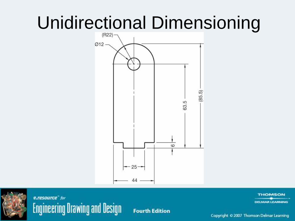
Unidirectional Dimensioning• Commonly used in mechanical drafting
• All numbers, figures, and notes read from
bottom
– Lettered horizontally on page
Unidirectional Dimensioning

Aligned Dimensioning• Read from
– Bottom
• Horizontal dimension
– Right
• Vertical dimension

Aligned Dimensioning
Tabular Dimensioning• Size and location dimensions in table
– X, Y, and Z axes defined
– Features related to table by symbols

Tabular Dimensioning
Arrowless Dimensioning• Ordinate dimensioning
• Features keyed to a table
• Location dimensions
– Established with extension lines
• Determined by datums

Arrowless Dimensioning
Chart Drawings• Used when
– Part or assembly has one or more dimensions
that change
• Dependent on application
• Variable dimension labeled with letter
• Commonly used in vendor or specification
catalogs

Chart Drawings
Part III
Dimensioning Rules

Decimal Points• Leading zeros
– Only for metric values less than one
• E.g., 0.08 mm
• Specified dimension
– Same number of decimal places as tolerance

Fractions• Separate whole numbers from fractions with
dash
– E.g. 1-5/8, not 1 5/8
• Use stacked fractions whenever possible

Chain Dimensioning• Point-to-point dimensioning
– Dependent on previous dimension(s)
– Avoid tolerance buildup
• Overall dimension
– Critical
– Stands independent in relationship to other
dimensions
• Let one dimension “float”
Preferred Dimensioning• Avoid crossing extension lines
– With other extension lines
• Do not break when they cross
– With dimension lines
– Over arrowheads
• Break when they cross
• Avoid dimensioning over or through an
object

Preferred Dimensioning• Avoid
– Dimensioning to hidden features
– Unnecessarily long extension lines
– Using object lines as extension lines
• Dimension between views when possible
• Group adjacent dimensions
• Dimension to view that provide best shape
description
Preferred Dimensioning• Dimension multiple features of the same
size with a note
– Specifies the number of “like” features
• Point leader arrow to center of circle
• Dimension circles with diameters
• Dimension arcs and fillets with radii

Location Dimensions• Rectangular shapes
– Located to sides
• Symmetrical features
– Located to centerline or centerplane
• Cylindrical features
– Given to center of feature
– Dimension in view where they appear as circles
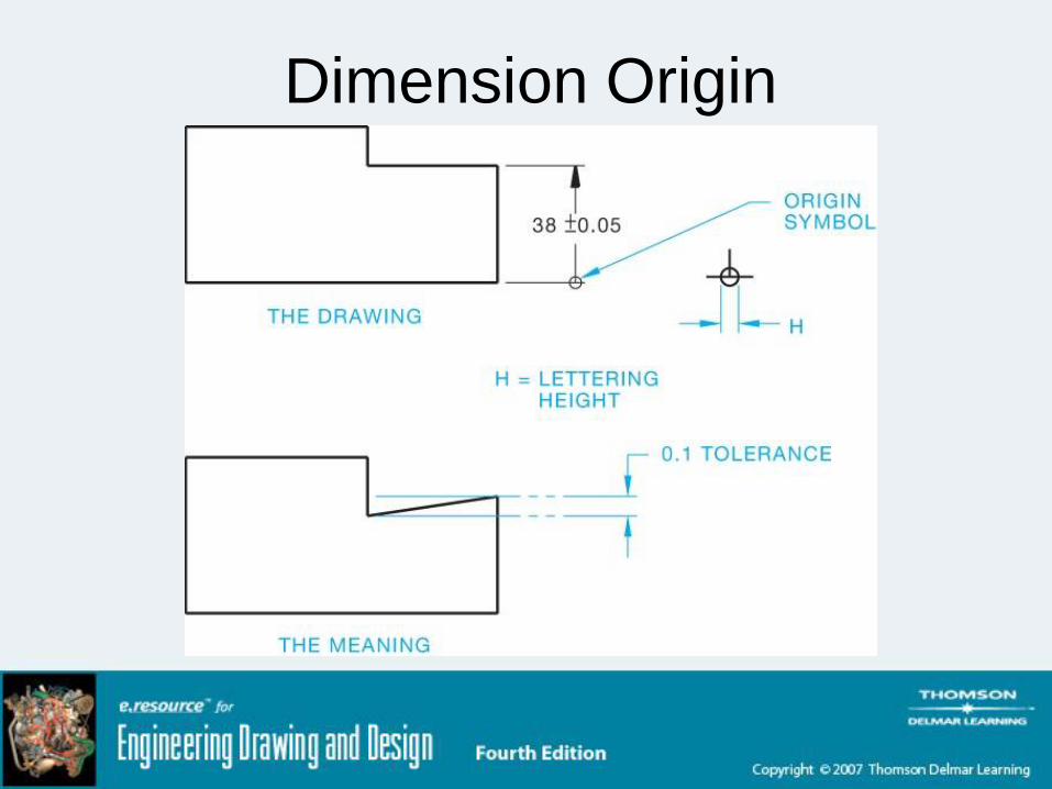
Dimension Origin

Part IV
Notes and Symbols

Counterbore• Machine a diameter below part surface
– Bolt head may be recessed
• Symbol
– Same as for spotface

Counterbore

Countersink• Counterdrill
• Recess head of fastener below part surface
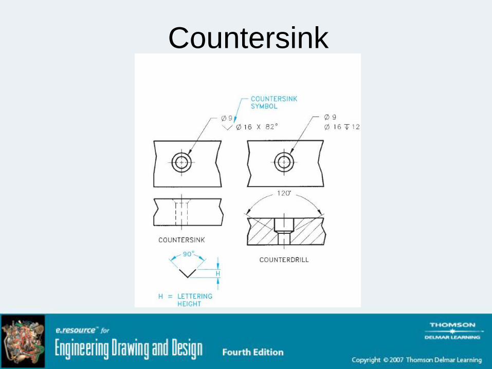
Countersink
Slots• Full radius
– Dimension one of three ways
• End radius > feature width
– Dimension end radii
– Dimension feature width
– Dimension feature length

Slots

Surface Finishes• When object surfaces are machined to
certain specification
• May appear in a general note
• May be connected to specific surface with
leader
• FAO
– Finish all over

Surface Finishes
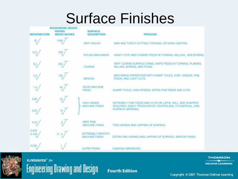
Surface Finishes

General Notes• Material specifications
• Dimensions
• General tolerances
• Confidential note, copyrights, patents
• Drawn by
• Scale
• Date
• Part name

General Notes• Drawing size
• Part number
• Number of revisions
• Type of projection (first or third)
• Standard reference (e.g., ANSI/ASME)
• General machining, finish, or paint specifications
• Identification of “like” features

Delta Notes• Triangle placed on a drawing
– Commonly, next to a dimension
– Hexagons and circles also used
• Cross-references a general note by number
• E.g, 2.625
– This dimension should refer to general note #1
1

Part V
Tolerancing

Calculating Tolerances• For example
– 22.0 ± 0.1
• Upper limit
– 22.1
• Lower limit
– 21.9
• Tolerance
– 0.2

Fit Tables - ANSI• RC
– Running clearance
• LC– Locational clearance
• LT– Transitional clearance
• LN– Locational interference
• FN– Force fit
Fit Tables - ISO• Hole basis
– Clearance Fit
• H11/c11
• H9/d9
• H8/f7
• H7/g6
• H7/h6

Fit Tables - ISO• Hole basis
– Transition fit
• H7/k6
• H7/n6
– Interference fit
• H7/p6
• H7/s6
• H7/u6
Summary• Use conventional dimensioning practices
– Continuity
– Accuracy
– Ease of interpretation
• Specify tolerances that are appropriate for
part application and machining ability