Dimensioning and Engineering rules...Dimensioning and Engineering Rules Page 9/33 4.1.1.3 Maximum...
33
© This document has been developed and released by UNISIG SUBSET-040 2.3.0 Dimensioning and Engineering Rules Page 1/33 ERTMS/ETCS – Class 1 Dimensioning and Engineering rules REF : SUBSET-040 ISSUE : 2.3.0 DATE : 7.4.2009 Company Technical Approval Management approval ALSTOM ANSALDO BOMBARDIER INVENSYS SIEMENS THALES
Transcript of Dimensioning and Engineering rules...Dimensioning and Engineering Rules Page 9/33 4.1.1.3 Maximum...
© This document has been developed and released by UNISIG
SUBSET-040 2.3.0
Dimensioning and Engineering Rules Page 1/33
ERTMS/ETCS – Class 1
Dimensioning and Engineering rules
REF : SUBSET-040
ISSUE : 2.3.0 DATE : 7.4.2009
Company Technical Approval Management approval
ALSTOM
ANSALDO
BOMBARDIER
INVENSYS
SIEMENS
THALES
© This document has been developed and released by UNISIG
SUBSET-040 2.3.0
Dimensioning and Engineering Rules Page 2/33
1. MODIFICATION HISTORY Issue Number
Date Section Number Modification / Description Author
0.0.1
22-jun-99
All First issue NG
0.0.2
25-jun-99
3.2
4.1.1.4 – 4.1.1.5
4.1.2.1 – 4.1.2.2
4.3.2.1 (f)
After meeting 24-Jun-99 NG
0.0.3
9-jul-99
All After comments from WGE group
NG
0.1.0
17-sept-99
3.1 – 3.2
4.1.1 note
4.1.1.1.b
4.1.1.2 – 3 – 4 – 5 – 6 4.1.1.7 – 8 – 9 – 10
4.1.1.11
4.1.2.1 – 4.2.1.2
4.2.2.1 – 3
4.3.1.1. b – c
4.3.2.1 all
4.3.3.1 – 4.3.4.1
Appendix
After meeting 2-Sept-99 NG
0.1.1
13-Oct-99
4.1.1 – note
4.1.1.1 a – b
4.1.1.4 – 5 – 7 – 9
4.1.1.10 – 12
4.1.2.1
4.1.3
4.2.2.3
4.2.3
4.3.2
Appendix
After meeting 6-Oct-99 NG
1.0.0
28-Oct-99
4.1.1.1 a
4.1.1.12
After comments from WGE group
NG

© This document has been developed and released by UNISIG
SUBSET-040 2.3.0
Dimensioning and Engineering Rules Page 3/33
1.0.1
29-Oct-99
4.1.1.1 a After comments from WGE group
NG
1.0.2
23-Feb-00
All (including re-numbering of the sections), after meeting 22-Feb-00
NG
1.1.0
24-Feb-00
Final for distribution U. Dräger (ed)
1.1.1
29-Mar-00
Modified: 3.1; 3.2.1.1; 3.2.1.3; 3.2.1.4; 3.2.2.2; 3.2.2.3; 3.3.1.3; 3.3.1.5; 3.4.1.2; 3.4.1.4; 4.1.1.1; 4.1.1.2; 4.1.1.4; 4.1.1.5; 4.1.1.6; 4.1.1.8; 4.1.2.1; 4.1.2.2; 4.1.4.1; 4.2.1.1; 4.2.2.1; 4.2.4.1; 4.3.2; 4.3.3.1
added: 3.2.1.5; 4.1.2.3; 4.2.4.2; 4.2.4.4
deleted: 4.1.4.2
NG+PZ
2.0.0
30-03-00
Final Issue to ECSAG D. Degavre
2.0.2
working draft
All Updates up to and including SG 14.02.2006
Ado
2.0.3
17/05/06
All Release Version HK
2.0.4
04/08/06
All After comments from EEIG Ado
2.1.0
9/10/06
Final for distribution Ado
2.3.0
7/4/09
Release Version: Document updated to be in line with 2.3.0d plus “DC” CRs 302, 654, 690, 691, 692, 693
HK

© This document has been developed and released by UNISIG
SUBSET-040 2.3.0
Dimensioning and Engineering Rules Page 4/33
2. TABLE OF CONTENTS 1. Modification History...........................................................................................................2
2. Table of Contents..............................................................................................................4
3. Introduction .......................................................................................................................5
3.1 References .......................................................................................................................5
3.2 Aim and purpose for a subset of engineering rules ...........................................................5
3.2.1 ERTMS/ETCS engineering rules ...................................................................................5
3.2.2 Transmission systems other than ERTMS/ETCS ..........................................................6
3.3 Referencing balises and antennas ....................................................................................6
3.3.1 Referencing balises and balise groups ..........................................................................6
3.3.2 Referencing antennas ...................................................................................................7
3.4 Definitions: ........................................................................................................................7
4. Rules.................................................................................................................................8
4.1 Installation rules ................................................................................................................8
4.1.1 Rules for balises............................................................................................................8
4.1.2 Rules for Eurobalise antenna ......................................................................................15
4.1.3 Rules for Euroloops .....................................................................................................16
4.1.4 Miscellaneous..............................................................................................................17
4.2 Telegrams and messages...............................................................................................18
4.2.1 Balise telegrams..........................................................................................................18
4.2.2 Radio messages..........................................................................................................18
4.2.3 Intentionally deleted.....................................................................................................19
4.2.4 Data engineering rules for individual data types ..........................................................19
4.3 Dimensioning rules for messages ...................................................................................24
4.3.1 Constraints ..................................................................................................................24
4.3.2 Data.............................................................................................................................24
4.3.3 Intentionally deleted.....................................................................................................31
4.3.4 Multiple instances of Packets ......................................................................................31
4.3.5 Data flows....................................................................................................................31
4.4 Intentionally deleted ........................................................................................................32
5. Appendix: RULES for KER COMPATIBILITY..................................................................33
© This document has been developed and released by UNISIG
SUBSET-040 2.3.0
Dimensioning and Engineering Rules Page 5/33
3. INTRODUCTION
3.1 References
3.1.1.1 The following documents are referenced in this document
• Interoperability-related consolidation on TSI Annex A documents – SUBSET-108 v1.2.0
• System Requirement Specification - SUBSET-026 v2.3.0
• Safety Requirements for Technical Interoperability of ETCS in Levels 1 & 2 – SUBSET-091 v2.3.0
• Specific transmission module FFFIS – SUBSET-035 v2.1.1
• FFFIS for Eurobalise – SUBSET-036 v2.4.1
• FFFIS for Euroloop – SUBSET-044 v2.3.0
• Assignment of values to ETCS variables – SUBSET-054 v2.0.0
• FIS for Euroradio – SUBSET-037 v2.3.0
• Interface ´G´ Specification – SUBSET-100 v1.0.1
• Interface ‘K’ Specification – SUBSET-101 v1.0.0
3.1.1.2 Intentionally deleted
3.1.1.3 Intentionally deleted
3.2 Aim and purpose for a subset of engineering rul es
3.2.1 ERTMS/ETCS engineering rules
3.2.1.1 The engineering rules are system-related limitations for installation of equipment, exchange of information, etc. that characterise the implementation of ERTMS subsystems.
3.2.1.2 These engineering rules provide additional constraints to the requirements stated in the SRS and other sub-level documents in order to ensure interoperability. There shall be no divergent requirements in these documents and the engineering rules.
3.2.1.2.1 The Engineering Rules stated here are therefore complementary to the requirements stated in the SRS and subdocuments (FFFS and FFFIS). References herein to other documents are not exhaustive, in particular to the SRS.
© This document has been developed and released by UNISIG
SUBSET-040 2.3.0
Dimensioning and Engineering Rules Page 6/33
3.2.1.3 Intentionally deleted
3.2.1.4 The aim of these engineering rules is not to define the whole set of rules necessary to realise a project with ERTMS/ETCS.
Additional rules, which are not defined in this document, may be needed, and may vary depending on the project constraints, Clients requirements or rules and Industry procedures. However, those rules must not preclude the use of any equipment meeting the engineering rules stated here.
3.2.1.5 The engineering rules defined stated herein or referenced are mandatory, Engineering advice is not in the scope of this document.
3.2.2 Transmission systems other than ERTMS/ETCS
3.2.2.1 Some constraints related to KER-compatible systems are described in appendix to this document.
3.2.2.2 Possible additional constraints related to transmission systems different from ERTMS (e.g. KER) must be defined within the relevant project.
3.3 Referencing balises and antennas
3.3.1 Referencing balises and balise groups
3.3.1.1 The reference location of a balise is the Balise Reference Marks, which are visible signs on the surface of the balise.
3.3.1.2 Balise groups will be considered as a complete device limited by the reference location of its outer balises.
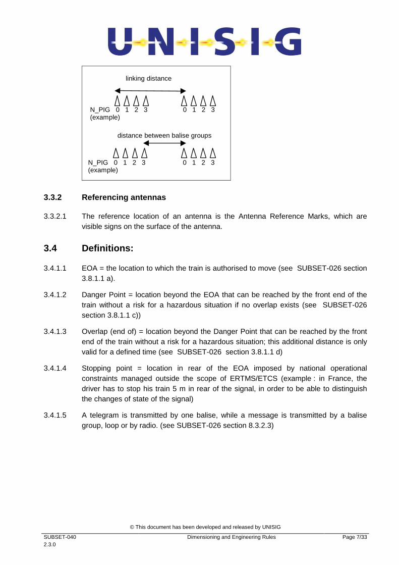
3.3.1.3 The reference location of a balise group is the reference location of its outer balise with N_PIG variable = 0.
3.3.1.4 The «last switchable balise» of a balise group refers to the last encountered switchable balise with regards to the balise group crossing direction.
3.3.1.5 Distance between balise groups is by definition the distance between closest balises of the two groups (i.e. between the Balise Reference Mark of the last one of the first group and the Balise Reference Mark of the first one of the second group).
• Note: This convention should not be mixed up with the distance used in the linking information (i.e. between the Balise Reference Mark of the balise with N_PIG variable = 0 of the first group and the Balise Reference Mark of the balise with N_PIG variable = 0 of the second group); see following figure
© This document has been developed and released by UNISIG
SUBSET-040 2.3.0
Dimensioning and Engineering Rules Page 7/33
N_PIG 0 1 2 3 0 1 2 3 (example)
N_PIG 0 1 2 3 0 1 2 3 (example)
linking distance
distance between balise groups
3.3.2 Referencing antennas
3.3.2.1 The reference location of an antenna is the Antenna Reference Marks, which are visible signs on the surface of the antenna.
3.4 Definitions:
3.4.1.1 EOA = the location to which the train is authorised to move (see SUBSET-026 section 3.8.1.1 a).
3.4.1.2 Danger Point = location beyond the EOA that can be reached by the front end of the train without a risk for a hazardous situation if no overlap exists (see SUBSET-026 section 3.8.1.1 c))
3.4.1.3 Overlap (end of) = location beyond the Danger Point that can be reached by the front end of the train without a risk for a hazardous situation; this additional distance is only valid for a defined time (see SUBSET-026 section 3.8.1.1 d)
3.4.1.4 Stopping point = location in rear of the EOA imposed by national operational constraints managed outside the scope of ERTMS/ETCS (example : in France, the driver has to stop his train 5 m in rear of the signal, in order to be able to distinguish the changes of state of the signal)
3.4.1.5 A telegram is transmitted by one balise, while a message is transmitted by a balise group, loop or by radio. (see SUBSET-026 section 8.3.2.3)
© This document has been developed and released by UNISIG
SUBSET-040 2.3.0
Dimensioning and Engineering Rules Page 8/33
4. RULES
4.1 Installation rules
4.1.1 Rules for balises
4.1.1.1 General installation rules for balises
Rule Reminder: the rules of the references below must be respected.
Reference SUBSET-036
� Section 4.2.5: Cross-talk protection
� Section 5.2 : Balise air gap interface
� Section 5.6.2 : Installation requirements for balises
� Section 5.6.3: Distance between balises
� Section 5.7: Environmental Conditions
Justification The rules of the reference above are required in order to guarantee interoperability from a transmission point of view.
4.1.1.2 Maximum distance between balises within a group – to determine that no further balise is expected within a group (potentially missing balise).
Rule The maximum distance between two consecutive balises within the same group shall be 12 m from reference mark to reference mark.
Reference
Justification The distance must be as short as possible in order to determine potential loss of balises as soon as possible, but must respect the longest minimum distance according to rule referenced in 4.1.1.1 herein.
© This document has been developed and released by UNISIG
SUBSET-040 2.3.0
Dimensioning and Engineering Rules Page 9/33
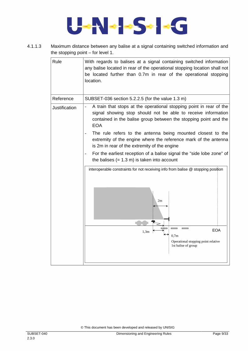
4.1.1.3 Maximum distance between any balise at a signal containing switched information and the stopping point – for level 1.
Rule With regards to balises at a signal containing switched information any balise located in rear of the operational stopping location shall not be located further than 0.7m in rear of the operational stopping location.
Reference SUBSET-036 section 5.2.2.5 (for the value 1.3 m)
Justification - A train that stops at the operational stopping point in rear of the signal showing stop should not be able to receive information contained in the balise group between the stopping point and the EOA
- The rule refers to the antenna being mounted closest to the extremity of the engine where the reference mark of the antenna is 2m in rear of the extremity of the engine
- For the earliest reception of a balise signal the ”side lobe zone” of the balises (= 1.3 m) is taken into account
interoperable constraints for not receiving info from balise @ stopping position
1,3m EOA
2m
Operational stopping point relative 1st balise of group
0,7m
© This document has been developed and released by UNISIG
SUBSET-040 2.3.0
Dimensioning and Engineering Rules Page 10/33
4.1.1.4 Minimum distance between the balise group and the EOA – for level 1.
Rule The last encountered balise of the balise group giving a MA, or giving an immediate level transition order, that is placed close to the EOA or LOA shall be a minimum distance of 1.3m in rear of the EOA/LOA.
Exception: This rule does not apply in case the level transition has been announced and the distance for the execution of the level transition has been engineered such that the level transition is performed before the EoA/LoA is passed.
Reference SUBSET-036 section 5.2.2.5 (for the value 1.3 m)
Justification - The underlying approach is that all information related to the extension of an MA or the level transition order at a border must have been received until the antenna with its reference mark overpasses the EoA/LoA location. From an on-board point of view this means that no further information will be received when the train with its “min safe antenna position” has passed the EoA/L0A.
- According to the FFFIS Eurobalise no further information can be received from a balise if the (on-board) antenna has passed a balise by a distance of more than 1.3m
- Note: For processing time limits of information received from balises refer to Subset 041, section 5.2 “response Times”
© This document has been developed and released by UNISIG
SUBSET-040 2.3.0
Dimensioning and Engineering Rules Page 11/33
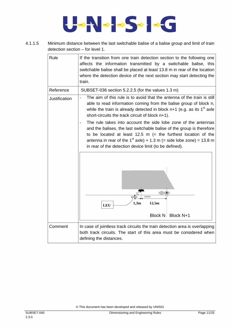
4.1.1.5 Minimum distance between the last switchable balise of a balise group and limit of train detection section – for level 1.
Rule If the transition from one train detection section to the following one affects the information transmitted by a switchable balise, this switchable balise shall be placed at least 13.8 m in rear of the location where the detection device of the next section may start detecting the train.
Reference SUBSET-036 section 5.2.2.5 (for the values 1.3 m)
Justification - The aim of this rule is to avoid that the antenna of the train is still able to read information coming from the balise group of block n, while the train is already detected in block n+1 (e.g. as its 1st axle short-circuits the track circuit of block n+1).
- The rule takes into account the side lobe zone of the antennas and the balises, the last switchable balise of the group is therefore to be located at least 12.5 m (= the furthest location of the antenna in rear of the 1st axle) + 1.3 m (= side lobe zone) = 13.8 m in rear of the detection device limit (to be defined).
Block N+1
12,5m 1,3m LEU
Block N
Comment In case of jointless track circuits the train detection area is overlapping both track circuits. The start of this area must be considered when defining the distances.

© This document has been developed and released by UNISIG
SUBSET-040 2.3.0
Dimensioning and Engineering Rules Page 12/33
4.1.1.6 Number of balises that can be processed per unit of time
Rule Let “d” be the distance run by a train at the maximum speed of the line during 0.8 s.
In this distance “d”, the number of encountered balises shall not exceed 8.
Note: The maximum speed of the line is the nominal line speed value (engineered SSP). Tolerances due to inaccuracy of speed measurements and speed margins before brake intervention are not to be taken into account for engineering.
Reference Limitations of SUBSET-036 - section 4.2.9 must be considered
Justification The rule is linked to processing of balise information on-board
Remark Figure
Interoperable constraints to ensure that all the balises can be processed on-board
≥9 balises received in window d : NOT OK
≤ 8 balises received in window d : OK
4.1.1.7 Intentionally deleted
© This document has been developed and released by UNISIG
SUBSET-040 2.3.0
Dimensioning and Engineering Rules Page 13/33
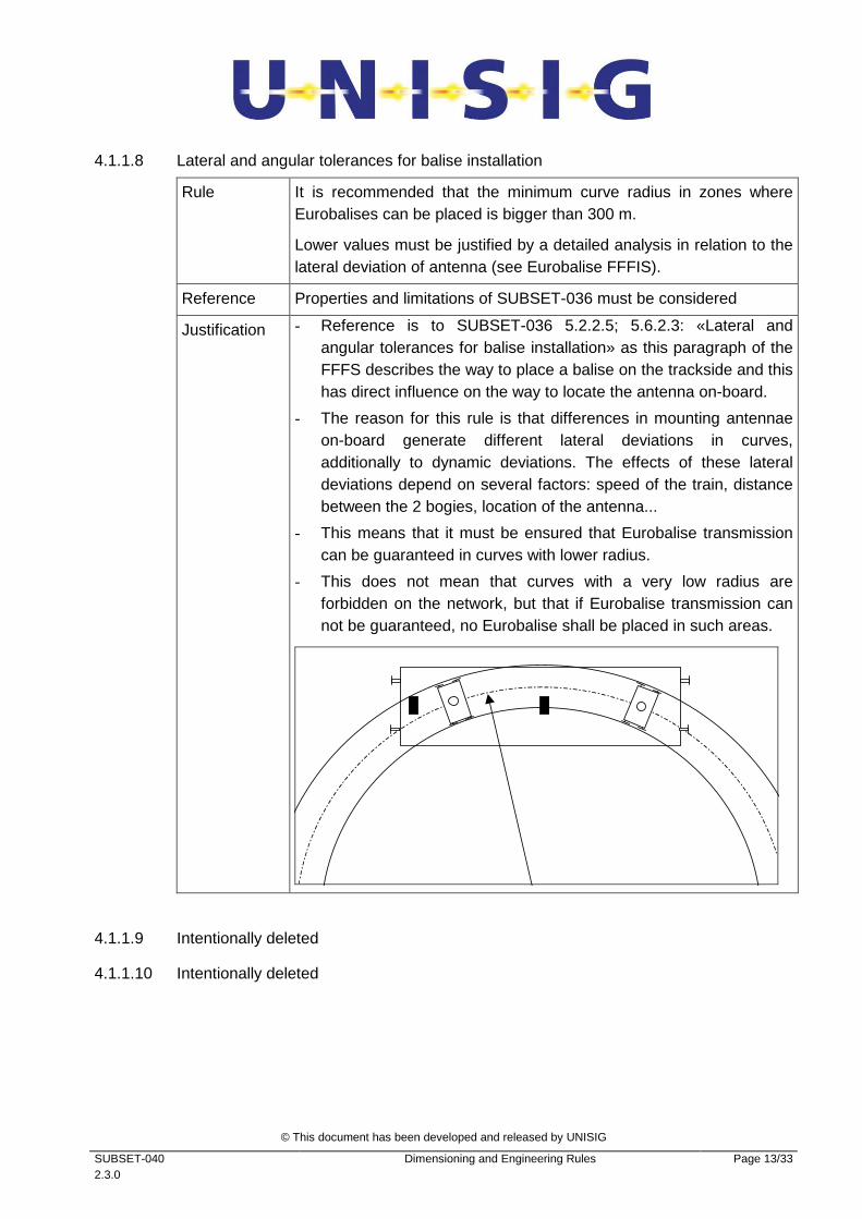
4.1.1.8 Lateral and angular tolerances for balise installation
Rule It is recommended that the minimum curve radius in zones where Eurobalises can be placed is bigger than 300 m.
Lower values must be justified by a detailed analysis in relation to the lateral deviation of antenna (see Eurobalise FFFIS).
Reference Properties and limitations of SUBSET-036 must be considered
Justification - Reference is to SUBSET-036 5.2.2.5; 5.6.2.3: «Lateral and angular tolerances for balise installation» as this paragraph of the FFFS describes the way to place a balise on the trackside and this has direct influence on the way to locate the antenna on-board.
- The reason for this rule is that differences in mounting antennae on-board generate different lateral deviations in curves, additionally to dynamic deviations. The effects of these lateral deviations depend on several factors: speed of the train, distance between the 2 bogies, location of the antenna...
- This means that it must be ensured that Eurobalise transmission can be guaranteed in curves with lower radius.
- This does not mean that curves with a very low radius are forbidden on the network, but that if Eurobalise transmission can not be guaranteed, no Eurobalise shall be placed in such areas.
4.1.1.9 Intentionally deleted
4.1.1.10 Intentionally deleted
© This document has been developed and released by UNISIG
SUBSET-040 2.3.0
Dimensioning and Engineering Rules Page 14/33
4.1.1.11 Balise group configurations
Rule Reminder: the rules of the reference below must be respected regards
- Number of balises in each group/use of single balise groups
- TSR Balise groups
Reference SUBSET-091 – section 8.3.2.1
Justification
4.1.1.12 Balise installation relative to track locations
Rule The in-fill location reference given by the in-fill device must be in rear of the current EOA.
Reference SUBSET-026 – section 3.4.3.1; 3.8.4.6.2-4; 4.8.1.5
Justification An MA extension via an in-fill MA is only possible if there is no gap between the old MA and the MA extension.
4.1.1.13 Balise installation relative to mission profile
Rule Reminder: the rules of the reference below must be respected e.g.
- Number of Unlinked Balise groups (marked as unlinked)
- Maximum distances between Balise groups
Reference SUBSET-091 – chapter 10 Mission Profile
Justification The safety analysis and safety requirements are based on this mission profile of the reference above.

© This document has been developed and released by UNISIG
SUBSET-040 2.3.0
Dimensioning and Engineering Rules Page 15/33
4.1.2 Rules for Eurobalise antenna
4.1.2.1 General installation rules for antennas (former 4.1.2.3)
Rule Reminder: Installation rules presented in FFFIS for Eurobalise shall be respected.
Reference SUBSET-036:
� Section 5.2 : Balise air gap interface
� Section 6.5 : Installation Requirements for Antennas
� Section 6.6: Specific Environmental Conditions for Antennas
� Section 6.7: Specific EMC Requirements for Antennas
Justification
4.1.2.2 Minimum / maximum distance between the front of the engine / 1st axle of the engine and the Eurobalise antenna
Rule The antenna shall be placed such that the Reference Mark of the balise antenna lies:
• between 2m from the front of the engine and the 1st axle : The minimum value of 2m shall be ensured taking into account dynamic effects of the coupling
• or, up to 12.5 m in the rear of the 1st axle.
The front of an engine shall be defined by the extremity on the side of the active cab, the “1st axle” as the axle closest to the front of the engine. For an engine with a cab on each side, one antenna is sufficient if the areas of both sides where the antenna can be placed overlap, and the antenna, regards its reference mark, is placed in the overlapping part.
max 12,5 m
allowed position for antenna
min 2 m
© This document has been developed and released by UNISIG
SUBSET-040 2.3.0
Dimensioning and Engineering Rules Page 16/33
Reference
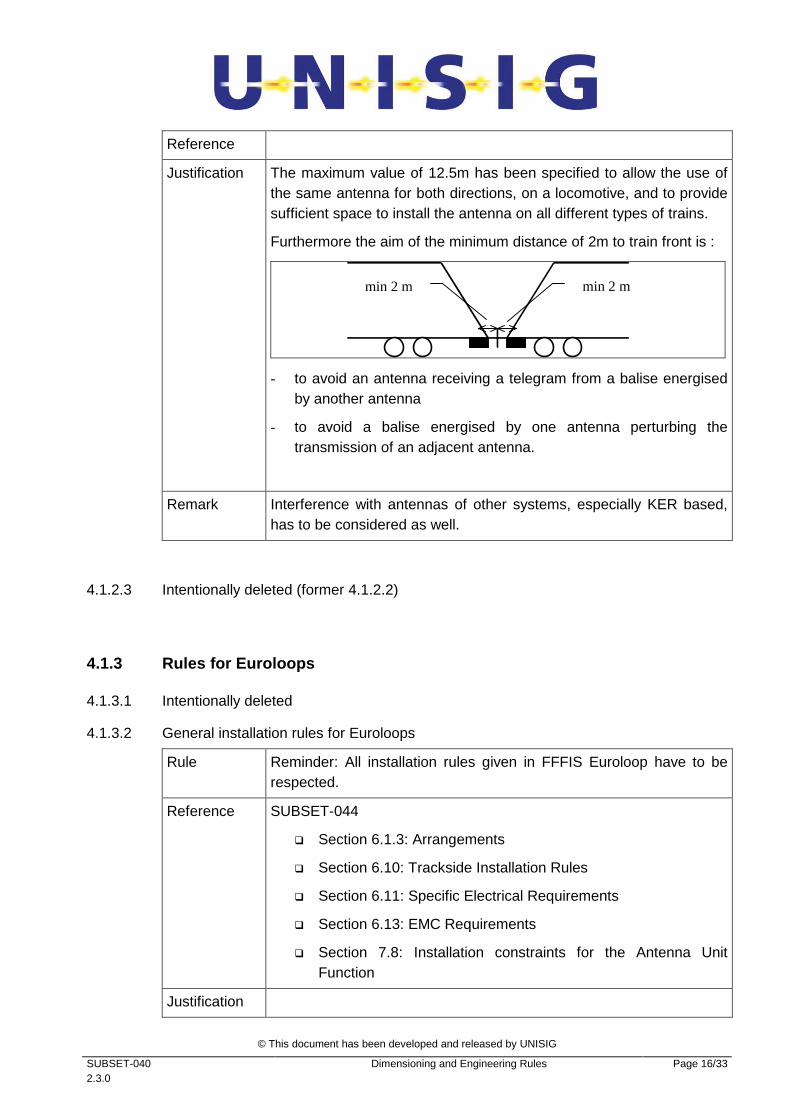
Justification The maximum value of 12.5m has been specified to allow the use of the same antenna for both directions, on a locomotive, and to provide sufficient space to install the antenna on all different types of trains.
Furthermore the aim of the minimum distance of 2m to train front is :
min 2 m min 2 m
- to avoid an antenna receiving a telegram from a balise energised by another antenna
- to avoid a balise energised by one antenna perturbing the transmission of an adjacent antenna.
Remark Interference with antennas of other systems, especially KER based, has to be considered as well.
4.1.2.3 Intentionally deleted (former 4.1.2.2)
4.1.3 Rules for Euroloops
4.1.3.1 Intentionally deleted
4.1.3.2 General installation rules for Euroloops
Rule Reminder: All installation rules given in FFFIS Euroloop have to be respected.
Reference SUBSET-044
� Section 6.1.3: Arrangements
� Section 6.10: Trackside Installation Rules
� Section 6.11: Specific Electrical Requirements
� Section 6.13: EMC Requirements
� Section 7.8: Installation constraints for the Antenna Unit Function
Justification
© This document has been developed and released by UNISIG
SUBSET-040 2.3.0
Dimensioning and Engineering Rules Page 17/33
4.1.4 Miscellaneous
4.1.4.1 Level transitions borders and RBC/RBC handover borders
Rule Level transition borders and RBC/RBC handover borders shall not be located where shunting or reversing could take place.
Reference SUBSET-026 sections 3.15.4.6, 4.4.8.1.5
Justification Level transitions and RBC/RBC handovers are not handled by the ERTMS/ETCS on-board equipment when in Shunting mode or in Reversing mode.
© This document has been developed and released by UNISIG
SUBSET-040 2.3.0
Dimensioning and Engineering Rules Page 18/33
4.2 Telegrams and messages
4.2.1 Balise telegrams
4.2.1.1 Length of balise telegrams (300 km/h, 500 km/h)
Rule • 0 - 300 km/h: long telegram or short telegram for both standard size and reduced size balises
• >300 - 500 km/h: long telegram or short telegram for standard size balises but only short telegram for reduced size balises
The speed values above are nominal line speed values (engineered SSP). Tolerances due to inaccuracy of speed measurements and speed margins before brake intervention are not to be taken into account for engineering.
Reference SUBSET-036 section 5.2.2.3;
for margins see SUBSET-026 A.3.1; for tolerances see SUBSET-041 – 5.3.1.2
Justification The rules are required in order to guarantee interoperability from a transmission point of view.
4.2.2 Radio messages
Note: Radio messages means RBC messages or radio in-fill messages (the same protocol is used in both cases)
4.2.2.1 Maximum length per message – to allow for the dimensioning of radio input buffers.
Rule Application data (excluding Euroradio protocol data) sent as normal priority data shall not exceed 500 bytes.
Reference
Justification - the length must be sufficient for MA - track description, according to 4.3.2.1 a)
- transmission delay
- more risk of perturbation
- size of EVC buffers
Remark A maximum number of bytes is not relevant for high priority data as only fixed size messages are used.
© This document has been developed and released by UNISIG
SUBSET-040 2.3.0
Dimensioning and Engineering Rules Page 19/33
4.2.3 Intentionally deleted
4.2.4 Data engineering rules for individual data ty pes
4.2.4.1 Intentionally deleted
4.2.4.2 Sharing of identifiers within different transmission systems
Rule Reminder: the rules of the reference below must be respected
Reference SUBSET-026, section 3.18.4.4.1
Justification
4.2.4.3 Intentionally deleted
4.2.4.4 Intentionally deleted
4.2.4.5 In-fill Information
4.2.4.5.1
Rule In-fill information which is repeated from the balise group at the next main signal by any in-fill device shall be limited to in-fill MA, linking and route related track description information. All information which does not relate to In-fill (e.g. information for opposite direction or EOLM etc.) shall not be given as in-fill information.
Permitted in-fill information:
- Packet 136 (in-fill location reference)
- Packet 12, 80; 49 (MA, Mode Profile, List of Balises for SH area)
- Packet 21 (Gradient Profile)
- Packet 27, 51, 65/66, 70 (SSP, ASP, TSR, Route Suitability)
- Packet 5 (Linking)
- Packet 41 (Level transition) {see also next rule below)
- Packet 44 (data used outside ERTMS)
- Packet 39, 67, 68 (Track condition)
- Packet 71 (adhesion factor)
- Packet 133 (Radio in-fill area information)
- Packet 138, 139 (Reversing area information)
Reference SUBSET-026 – section 3.8.4.6.3
Justification This is to avoid any misinterpretation by on-board.
© This document has been developed and released by UNISIG
SUBSET-040 2.3.0
Dimensioning and Engineering Rules Page 20/33
4.2.4.5.2
Rule If in-fill information contains an announcement of an immediate level transition at the location of the location reference for the in-fill information, for the distance D_LEVELTR the value of “0m” shall be used.
Justification For in-fill only distance based information can be interpreted on-board
4.2.4.6 Mode Profile
4.2.4.6.1
Rule The overlapping of mode profile areas in the mode profile packet shall be forbidden.
Reference
Justification There is no possibility to handle two mode profiles at the same location.
4.2.4.6.2
Rule In case there is a Level 1 MA Packet with V_MAIN = 0, it is not allowed that the Message includes any mode profile packet.
Reference SUBSET-026 – 4.6.2 & 4.6.3 transition [32]
Justification On one hand it is obvious that a “STOP” signal aspect shall not contain an Mode profile but on the other hand this rule is necessary to complete the transition table of the SRS (avoid a mode transition if Override is active).
© This document has been developed and released by UNISIG
SUBSET-040 2.3.0
Dimensioning and Engineering Rules Page 21/33
4.2.4.7 Track conditions
4.2.4.7.1
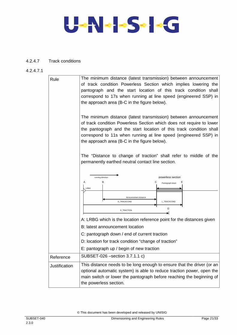
Rule The minimum distance (latest transmission) between announcement of track condition Powerless Section which implies lowering the pantograph and the start location of this track condition shall correspond to 17s when running at line speed (engineered SSP) in the approach area (B-C in the figure below).
The minimum distance (latest transmission) between announcement of track condition Powerless Section which does not require to lower the pantograph and the start location of this track condition shall correspond to 11s when running at line speed (engineered SSP) in the approach area (B-C in the figure below).
The “Distance to change of traction” shall refer to middle of the permanently earthed neutral contact line section.
E
D
powerless section
Pantograph down
running direction
C
LRBG
Announcement distance
D_TRACKCOND L_TRACKCOND
B A
D_TRACTION
A: LRBG which is the location reference point for the distances given
B: latest announcement location
C: pantograph down / end of current traction
D: location for track condition “change of traction”
E: pantograph up / begin of new traction
Reference SUBSET-026 –section 3.7.1.1 c)
Justification This distance needs to be long enough to ensure that the driver (or an optional automatic system) is able to reduce traction power, open the main switch or lower the pantograph before reaching the beginning of the powerless section.
© This document has been developed and released by UNISIG
SUBSET-040 2.3.0
Dimensioning and Engineering Rules Page 22/33
4.2.4.7.2
Rule The minimum distance (latest transmission) between announcement of track condition
- Non stopping area
- Air tightness
- Switch off regenerative/eddy current/magnetic shoe brake
and the start location of this track condition shall correspond to 10s when running at line speed (engineered SSP) in the approach area.
Reference SUBSET-026 –section 3.7.1.1 c)
Justification This distance needs to be long enough to ensure that the driver (or an optional automatic system) is able perform the related action before reaching the beginning of the track condition.
4.2.4.8 Linking data handling
4.2.4.8.1
Rule Balise groups with balise group qualifier “unlinked” shall never be announced via linking.
Reference
Justification This is to avoid any contradiction between the consistency reaction regarding “Unlinked” balise groups and the one regarding announced linking reaction.
4.2.4.8.2
Rule Balise groups with balise group qualifier “unlinked” shall never be used to transmit linking information unless it is sent as in-fill information (see 4.2.4.5 herein).
Reference SUBSET-026 – section 3.6.1.4
Justification Balise groups with a balise group qualifier “unlinked” can never become an LRBG.
This rule aims at reducing system complexity caused by the relocation of information received from a mixture of linked and unlinked balise groups which in addition only leads to a degradation of performance.
© This document has been developed and released by UNISIG
SUBSET-040 2.3.0
Dimensioning and Engineering Rules Page 23/33
4.2.4.9 Level transition announcement
4.2.4.9.1
Rule Reminder: All “Engineering requirements for Level transition” involving STM given in FFFIS STM have to be respected.
Reference SUBSET-035 section 7.5
Justification
4.2.4.9.2
Rule Trackside shall announce all applicable values of NID_STM containing the national system(s) installed in the infrastructure.
Reference SUBSET-026 sections 7.4.2.9; 7.5.1.98
Justification Certain STM functionalities might be grouped and so the trackside has to announce all relevant stand-alone STMs as well as STM groups according to the NID_STM list.
4.2.4.10 Text transmission
Rule The use of the end condition “location” shall be allowed only if the start condition 'location" is used.
Reference SUBSET-026 – section 3.12.3.4; 7.4.2.23/24
Justification
4.2.4.11 Packet 131 (RBC Transition Order)
Rule It shall be forbidden to use the special value “Contact the last known RBC” for the RBC ETCS identity number NID_RBC.
Reference SUBSET-026 – section 7.5.1.96
Justification Using the special value “Contact the last known RBC” would point to the Handing Over RBC which makes no sense in announcing an RBC Handover
© This document has been developed and released by UNISIG
SUBSET-040 2.3.0
Dimensioning and Engineering Rules Page 24/33
4.2.4.12 NID_RADIO
Rule For information regards the NID_RADIO refer to Subset 054
Reference
Justification
4.3 Dimensioning rules for messages
4.3.1 Constraints
4.3.1.1 The maximum number of iterations of the same type of information:
Rule In case the Engineering rules limit the number of iterations of a certain type of information, this shall take precedence over the 31 (= maximum of N_ITER) iterations stated in chapter 7 of the SRS.
Reference SUBSET-026 – section 7.5.1.77
Justification In chapter 7 of the SRS, a nominal value range for N_ITER was chosen in order to rationalise the ETCS language. Where specific limits for N_ITER are required, they are stated in the Engineering Rules document.
Remark
4.3.2 Data
4.3.2.1 List of data that are related to dimensioning rules:
4.3.2.1.1 Note: The value for the “Maximum number of iterations in 1 packet” in the rules below refers to the value of N_ITER in the related packets.
© This document has been developed and released by UNISIG
SUBSET-040 2.3.0
Dimensioning and Engineering Rules Page 25/33
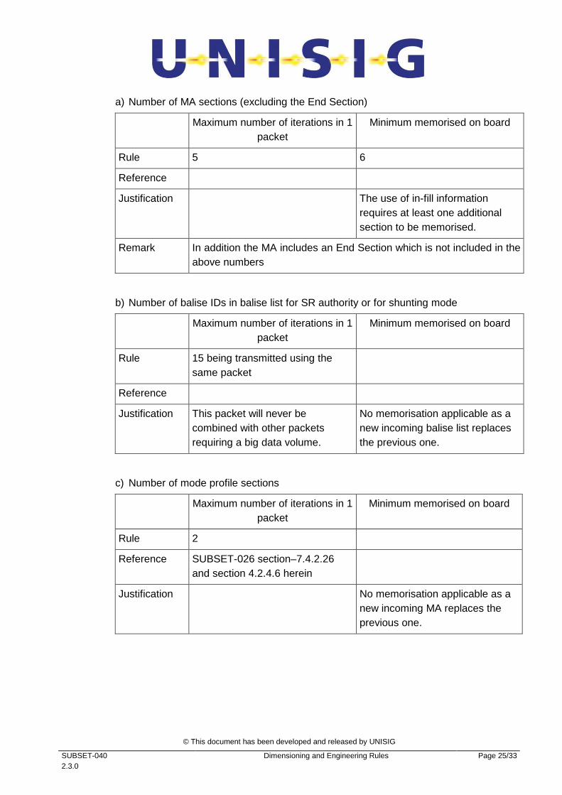
a) Number of MA sections (excluding the End Section)
Maximum number of iterations in 1 packet
Minimum memorised on board
Rule 5 6
Reference
Justification The use of in-fill information requires at least one additional section to be memorised.
Remark In addition the MA includes an End Section which is not included in the above numbers
b) Number of balise IDs in balise list for SR authority or for shunting mode
Maximum number of iterations in 1 packet
Minimum memorised on board
Rule 15 being transmitted using the same packet
Reference
Justification This packet will never be combined with other packets requiring a big data volume.
No memorisation applicable as a new incoming balise list replaces the previous one.
c) Number of mode profile sections
Maximum number of iterations in 1 packet
Minimum memorised on board
Rule 2
Reference SUBSET-026 section–7.4.2.26 and section 4.2.4.6 herein
Justification No memorisation applicable as a new incoming MA replaces the previous one.
© This document has been developed and released by UNISIG
SUBSET-040 2.3.0
Dimensioning and Engineering Rules Page 26/33
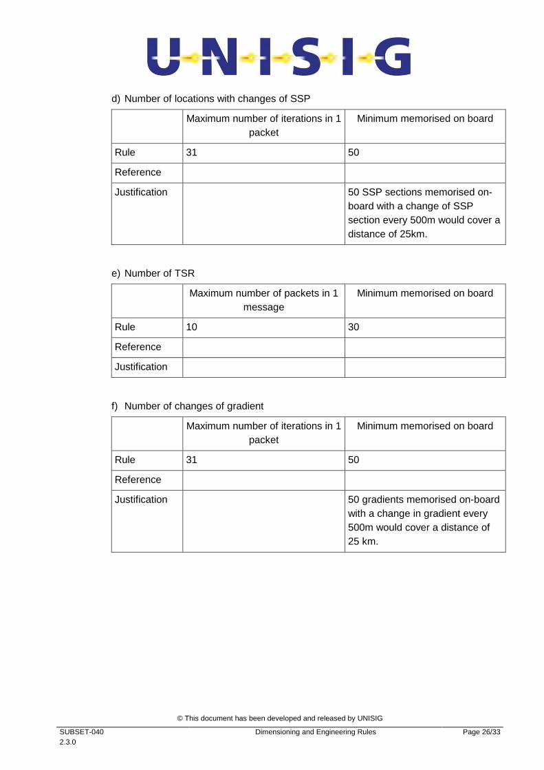
d) Number of locations with changes of SSP
Maximum number of iterations in 1 packet
Minimum memorised on board
Rule 31 50
Reference
Justification 50 SSP sections memorised on-board with a change of SSP section every 500m would cover a distance of 25km.
e) Number of TSR
Maximum number of packets in 1 message
Minimum memorised on board
Rule 10 30
Reference
Justification
f) Number of changes of gradient
Maximum number of iterations in 1 packet
Minimum memorised on board
Rule 31 50
Reference
Justification 50 gradients memorised on-board with a change in gradient every 500m would cover a distance of 25 km.

© This document has been developed and released by UNISIG
SUBSET-040 2.3.0
Dimensioning and Engineering Rules Page 27/33
g) Number of locations for position reports
Maximum number of iterations in 1 packet
Minimum memorised on board
Rule 15
Reference
Justification
Remark If a train gets a new packet 58 from the RBC, it replaces the old position report parameter.
h) Number of text messages
Maximum number of iterations in 1 packet
Minimum memorised on board
Rule 1 plain text + 1 fixed text 5 plain text + 5 fixed text
Reference
Justification
© This document has been developed and released by UNISIG
SUBSET-040 2.3.0
Dimensioning and Engineering Rules Page 28/33
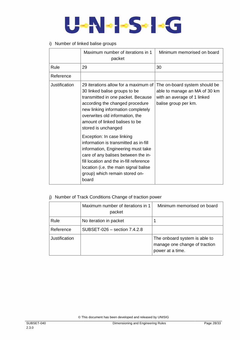
i) Number of linked balise groups
Maximum number of iterations in 1 packet
Minimum memorised on board
Rule 29 30
Reference
Justification 29 iterations allow for a maximum of 30 linked balise groups to be transmitted in one packet. Because according the changed procedure new linking information completely overwrites old information, the amount of linked balises to be stored is unchanged
Exception: In case linking information is transmitted as in-fill information, Engineering must take care of any balises between the in-fill location and the in-fill reference location (i.e. the main signal balise group) which remain stored on-board
The on-board system should be able to manage an MA of 30 km with an average of 1 linked balise group per km.
j) Number of Track Conditions Change of traction power
Maximum number of iterations in 1 packet
Minimum memorised on board
Rule No iteration in packet 1
Reference SUBSET-026 – section 7.4.2.8
Justification The onboard system is able to manage one change of traction power at a time.
© This document has been developed and released by UNISIG
SUBSET-040 2.3.0
Dimensioning and Engineering Rules Page 29/33
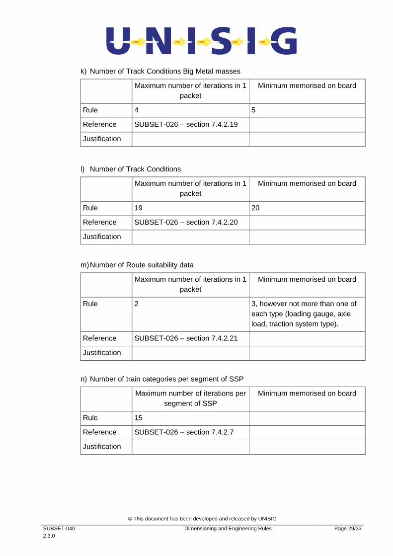
k) Number of Track Conditions Big Metal masses
Maximum number of iterations in 1 packet
Minimum memorised on board
Rule 4 5
Reference SUBSET-026 – section 7.4.2.19
Justification
l) Number of Track Conditions
Maximum number of iterations in 1 packet
Minimum memorised on board
Rule 19 20
Reference SUBSET-026 – section 7.4.2.20
Justification
m) Number of Route suitability data
Maximum number of iterations in 1 packet
Minimum memorised on board
Rule 2 3, however not more than one of each type (loading gauge, axle load, traction system type).
Reference SUBSET-026 – section 7.4.2.21
Justification
n) Number of train categories per segment of SSP
Maximum number of iterations per segment of SSP
Minimum memorised on board
Rule 15
Reference SUBSET-026 – section 7.4.2.7
Justification
© This document has been developed and released by UNISIG
SUBSET-040 2.3.0
Dimensioning and Engineering Rules Page 30/33
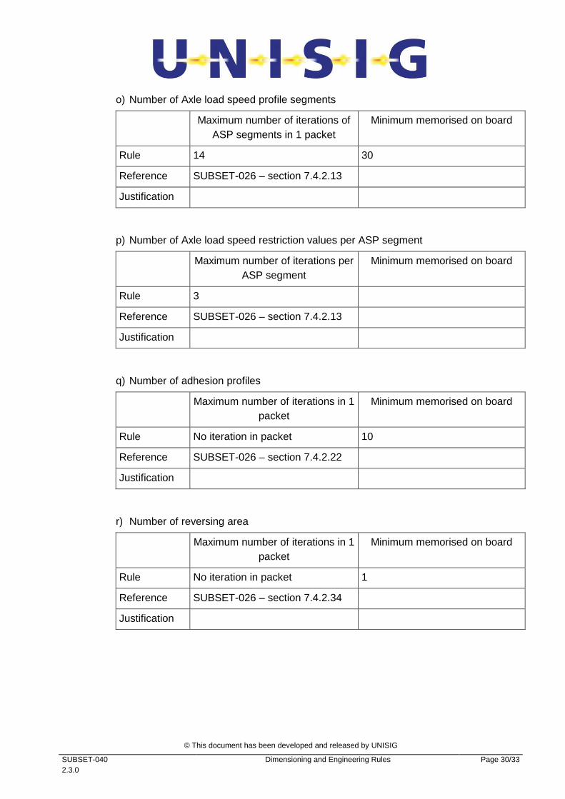
o) Number of Axle load speed profile segments
Maximum number of iterations of ASP segments in 1 packet
Minimum memorised on board
Rule 14 30
Reference SUBSET-026 – section 7.4.2.13
Justification
p) Number of Axle load speed restriction values per ASP segment
Maximum number of iterations per ASP segment
Minimum memorised on board
Rule 3
Reference SUBSET-026 – section 7.4.2.13
Justification
q) Number of adhesion profiles
Maximum number of iterations in 1 packet
Minimum memorised on board
Rule No iteration in packet 10
Reference SUBSET-026 – section 7.4.2.22
Justification
r) Number of reversing area
Maximum number of iterations in 1 packet
Minimum memorised on board
Rule No iteration in packet 1
Reference SUBSET-026 – section 7.4.2.34
Justification
© This document has been developed and released by UNISIG
SUBSET-040 2.3.0
Dimensioning and Engineering Rules Page 31/33
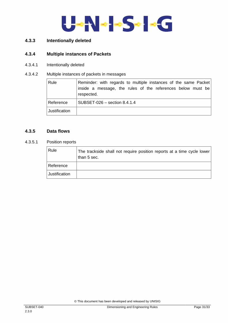
4.3.3 Intentionally deleted
4.3.4 Multiple instances of Packets
4.3.4.1 Intentionally deleted
4.3.4.2 Multiple instances of packets in messages
Rule Reminder: with regards to multiple instances of the same Packet inside a message, the rules of the references below must be respected.
Reference SUBSET-026 – section 8.4.1.4
Justification
4.3.5 Data flows
4.3.5.1 Position reports
Rule The trackside shall not require position reports at a time cycle lower than 5 sec.
Reference
Justification

© This document has been developed and released by UNISIG
SUBSET-040 2.3.0
Dimensioning and Engineering Rules Page 32/33
4.4 Intentionally deleted
© This document has been developed and released by UNISIG
SUBSET-040 2.3.0
Dimensioning and Engineering Rules Page 33/33
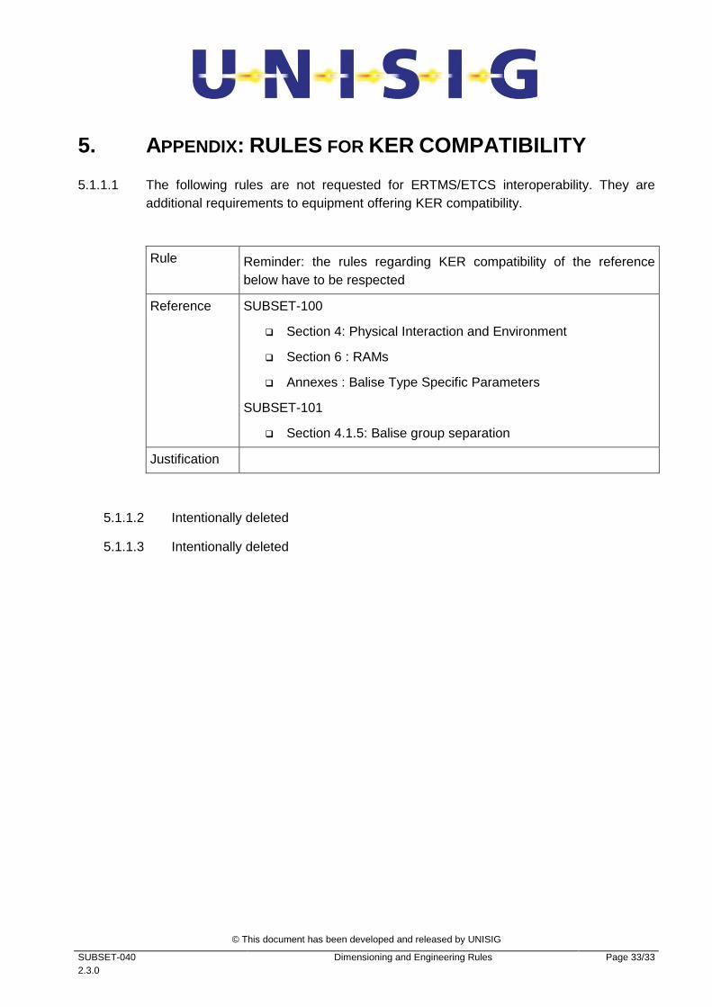
5. APPENDIX: RULES FOR KER COMPATIBILITY
5.1.1.1 The following rules are not requested for ERTMS/ETCS interoperability. They are additional requirements to equipment offering KER compatibility.
Rule Reminder: the rules regarding KER compatibility of the reference below have to be respected
Reference SUBSET-100
� Section 4: Physical Interaction and Environment
� Section 6 : RAMs
� Annexes : Balise Type Specific Parameters
SUBSET-101
� Section 4.1.5: Balise group separation
Justification
5.1.1.2 Intentionally deleted
5.1.1.3 Intentionally deleted