Digitally-Controlled Electrical Balance Duplexer for ... · PDF fileDigitally-Controlled...
8
Digitally-Controlled Electrical Balance Duplexer for Transmitter-Receiver Isolation in Full-Duplex Radio Enrico Manuzzato 1, 2 , Joose Tamminen 1 , Matias Turunen 1 , Dani Korpi 1 , Fabrizio Granelli 2 , and Mikko Valkama 1 1 Tampere University of Technology, Department of Electronics and Communications Engineering, Korkeakoulunkatu 1, FI-33720 Tampere, FINLAND 2 University of Trento, Department of Information Engineering and Computer Science, ITALY Contact email: [email protected] Abstract— This paper presents a novel digitally-controlled electrical balance duplexer (EBD) prototype capable of inband full- duplex radio communications. The developed EBD prototype works in the ISM-Band, at 2.4-2.48 GHz, and can achieve TX to RX isolation of 53 dB across an 80 MHz instantaneous bandwidth. The prototype is composed of three parts, namely coupled line hybrid junction, triple-Pi balancing impedance and antenna tuning unit (ATU) which are all realized with commercial off-the-shelf components and implemented over a two layer FR4 board. The EBD contains also a self-adaptive or self-healing digital control system enabling automatic tracking of time-varying antenna impedance characteristics, providing robustness against fast changes in the surrounding environment and against user interactions. In addition to the architecture and operating principle descriptions, we also provide actual RF measurements at 2.4 GHz ISM band with real antenna connected, demonstrating the achievable isolation levels with different bandwidths and when operating in different environmental conditions. Furthermore, isolation performance is measured when operating with different antennas and under a low-cost highly nonlinear power amplifier. Keywords- Antenna tuning, digital control, electrical balance duplexer, full-duplex radio, hybrid junction, self-interference tracking, transmitter-receiver isolation I. INTRODUCTION The ever-increasing needs of higher data rates and massively increasing device populations are creating constant push towards developing new methods and technologies to increase the capacity of wireless communication networks. As the date rates and network capacity are strongly connected to the amount of the available radio spectrum, which is generally a very scarce resource, finding ways to increase the efficiency and flexibility of the spectrum utilization is one of the most essential targets and ingredients towards the 5G radio networks. In general, all existing radio communication systems exploit either time division duplexing (TDD) or frequency division duplexing (FDD), to enable bidirectional communication, where transmission and reception in an individual device are separated either in time or frequency. Thus, one intriguing method to increase the flexibility and efficiency of the radio spectrum use is to transmit and receive simultaneously at the same center- frequency, commonly referred to as the in-band full-duplex (FD) radio principle. Such technology can in principle double the spectral efficiency of an individual radio link, and more generally increase the network capacity and spectral efficiency, while also potentially simplifying, e.g., the radio network frequency planning [1]. One of the key technical challenges in FD communications is related to the suppression of the massively strong self-interference (SI), which is caused by the collocated transmitter (TX) and receiver (RX) operating simultaneously at the same carrier. As the TX signal can in general be in the order of 100-120dB stronger than the weak received signal, especially if the RX is operating close to its own sensitivity level, the overall TX-RX isolation requirements in the FD radio units are massively high, calling for novel antenna, RF circuit and digital signal processing solutions for their realization. In the existing literature, several methods and solutions have been presented to suppress or mitigate the self- interference in FD radio transceivers. In general, providing elementary isolation between the TX and RX in RF domain can be building on specific antenna technologies, circulators, or hybrid junction based electrical balance duplexers. On top of these, active SI cancellation is also typically required, either at analog/RF stages or digital baseband or both. State-of-the-art analog RF cancelers, such as the one reported in [2], can typically provide 30-50dB of active SI suppression, while 20- 30dB of passive isolation through separate and potentially directional TX and RX antennas has been reported in [3], [4]. Furthermore, specific multiantenna/MIMO solutions have been reported, e.g., in [5], evidencing 20-30dB of TX-RX isolation through creating spatial nulls towards own RX antennas with properly controlled TX array. This, however, has the downside of calling for separate TX and RX antennas/arrays, which may potentially be feasible in, e.g., relay type of devices but not in smaller form-factor consumer devices. The ability to share an antenna between the TX and RX chains can build on the adoption of a circulator, as was done, This work was funded by the Academy of Finland (under the project #259915 ”In-band Full-Duplex MIMO Transmission: A Breakthrough to High-Speed Low-Latency Mobile Networks”), Intel Corporation, and the Internet of Things program of DIGILE (Finnish Strategic Centre for Science, Technology and Innovation in the field of ICT) funded by Tekes.
-
Upload
vuongthien -
Category
Documents
-
view
224 -
download
0
Transcript of Digitally-Controlled Electrical Balance Duplexer for ... · PDF fileDigitally-Controlled...

Digitally-Controlled Electrical Balance Duplexer for Transmitter-Receiver Isolation in Full-Duplex Radio
Enrico Manuzzato1, 2, Joose Tamminen1, Matias Turunen1, Dani Korpi1, Fabrizio Granelli2, and Mikko Valkama1
1 Tampere University of Technology, Department of Electronics and Communications Engineering, Korkeakoulunkatu 1, FI-33720 Tampere, FINLAND
2 University of Trento, Department of Information Engineering and Computer Science, ITALY
Contact email: [email protected]
Abstract— This paper presents a novel digitally-controlled electrical balance duplexer (EBD) prototype capable of inband full-duplex radio communications. The developed EBD prototype works in the ISM-Band, at 2.4-2.48 GHz, and can achieve TX to RX isolation of 53 dB across an 80 MHz instantaneous bandwidth. The prototype is composed of three parts, namely coupled line hybrid junction, triple-Pi balancing impedance and antenna tuning unit (ATU) which are all realized with commercial off-the-shelf components and implemented over a two layer FR4 board. The EBD contains also a self-adaptive or self-healing digital control system enabling automatic tracking of time-varying antenna impedance characteristics, providing robustness against fast changes in the surrounding environment and against user interactions. In addition to the architecture and operating principle descriptions, we also provide actual RF measurements at 2.4 GHz ISM band with real antenna connected, demonstrating the achievable isolation levels with different bandwidths and when operating in different environmental conditions. Furthermore, isolation performance is measured when operating with different antennas and under a low-cost highly nonlinear power amplifier.
Keywords- Antenna tuning, digital control, electrical balance duplexer, full-duplex radio, hybrid junction, self-interference tracking, transmitter-receiver isolation
I. INTRODUCTION
The ever-increasing needs of higher data rates and massively increasing device populations are creating constant push towards developing new methods and technologies to increase the capacity of wireless communication networks. As the date rates and network capacity are strongly connected to the amount of the available radio spectrum, which is generally a very scarce resource, finding ways to increase the efficiency and flexibility of the spectrum utilization is one of the most essential targets and ingredients towards the 5G radio networks.
In general, all existing radio communication systems exploit either time division duplexing (TDD) or frequency division duplexing (FDD), to enable bidirectional communication, where
transmission and reception in an individual device are separated either in time or frequency. Thus, one intriguing method to increase the flexibility and efficiency of the radio spectrum use is to transmit and receive simultaneously at the same center-frequency, commonly referred to as the in-band full-duplex (FD) radio principle. Such technology can in principle double the spectral efficiency of an individual radio link, and more generally increase the network capacity and spectral efficiency, while also potentially simplifying, e.g., the radio network frequency planning [1]. One of the key technical challenges in FD communications is related to the suppression of the massively strong self-interference (SI), which is caused by the collocated transmitter (TX) and receiver (RX) operating simultaneously at the same carrier. As the TX signal can in general be in the order of 100-120dB stronger than the weak received signal, especially if the RX is operating close to its own sensitivity level, the overall TX-RX isolation requirements in the FD radio units are massively high, calling for novel antenna, RF circuit and digital signal processing solutions for their realization.
In the existing literature, several methods and solutions have been presented to suppress or mitigate the self-interference in FD radio transceivers. In general, providing elementary isolation between the TX and RX in RF domain can be building on specific antenna technologies, circulators, or hybrid junction based electrical balance duplexers. On top of these, active SI cancellation is also typically required, either at analog/RF stages or digital baseband or both. State-of-the-art analog RF cancelers, such as the one reported in [2], can typically provide 30-50dB of active SI suppression, while 20-30dB of passive isolation through separate and potentially directional TX and RX antennas has been reported in [3], [4]. Furthermore, specific multiantenna/MIMO solutions have been reported, e.g., in [5], evidencing 20-30dB of TX-RX isolation through creating spatial nulls towards own RX antennas with properly controlled TX array. This, however, has the downside of calling for separate TX and RX antennas/arrays, which may potentially be feasible in, e.g., relay type of devices but not in smaller form-factor consumer devices.
The ability to share an antenna between the TX and RX chains can build on the adoption of a circulator, as was done,
This work was funded by the Academy of Finland (under the project#259915 ”In-band Full-Duplex MIMO Transmission: A Breakthrough toHigh-Speed Low-Latency Mobile Networks”), Intel Corporation, and the Internet of Things program of DIGILE (Finnish Strategic Centre for Science,Technology and Innovation in the field of ICT) funded by Tekes.

e.g., in [2], [6], or of an electrical balance (EB) duplexing type of circuitry, as described in [7], [13]. Such electrical balance duplexer (EBD) can enable relatively high TX-RX isolations and dense integration at the same time, with various different demonstration scale implementations being reported in, e.g., [7]-[11]. These works report TX-RX isolations in the order of 30-50 dB. However, most of the reported works are limited to fairly narrow instantaneous bandwidths in the order of 5-20 MHz while the isolation performance often decreases heavily for higher bandwidth scenarios. These duplexers are also commonly designed and optimized for specific antenna characteristics, whose performance thus degrades fast when the antenna characteristics change.
In this paper, we present a novel digitally-controlled electrical-balance duplexer prototype, operating at 2.4GHz ISM band, which is able to achieve high TX-RX isolations with wideband RF waveforms. The prototype contains also a novel self-adaptive or self-healing digital control system enabling automatic tracking of time-varying antenna impedance characteristics, providing robustness against fast changes in the surrounding environment and against antenna-user interactions. Isolation measurements and performance results are presented also with different types of antennas and reflection scenarios. In general, more than 50dB of TX-RX isolation is reported through actual RF measurements with instantaneous bandwidth of 80MHz, and when operating with different types of antennas.
The rest of this paper is organized as follows. Section II gives an overview of the EBD working principle, while Section III presents then the architecture and design of the developed demonstrator circuitry. Section IV describes the operating principle and the associated learning algorithms of the self-adaptive digital control system, while the RF measurement setup and results are reported and analyzed in Section V. Finally, Section VI concludes the paper.
II. ELECTRICAL BALANCE DUPLEXER OPERATING PRINCIPLE
Figure 1 presents the basic structure of an EBD, together with elementary receiver circuitry used for the actual receiver functionalities as well as for facilitating the digital control of the EBD and its TX-RX isolation. Most typical EBD implementations integrate four core elements, namely a hybrid junction, an antenna, a balancing impedance and a control system for tuning the balancing impedance. An antenna tuning unit (ATU) can also be included as an optional element. These are elaborated in more details in the following.
A. Hybrid Junction
The hybrid junction or hybrid transformer is the core of any EBD. This device has several key properties including bi-conjugacy and isolation between alternate sets of ports, impedance matching at each port, as well as the ability to split the TX and RX power in any desired portion between two ports by choosing a proper tapping ratio r [8]. The TX-RX isolation can in general be derived via its S-matrix as done, e.g., in [8]. As a result, for 1r = implying symmetric splitting power ratio for simplicity, the isolation at a particular frequency w can be expressed as
Fig. 1. Principal structure of an electrical balance duplexer (EBD), together with the associated receiver circuitry.
2
, 10( ) 10 log ( ) ( ) 6TX RX dB ANT BALw w w-¡ = G - G - (1)
where
( ) ( )
( ) , ( )( ) ( )
BAL o ANT oBAL ANT
BAL o ANT o
Z Z Z Z
Z Z Z Z
w ww w
w w- -
G = G =+ +
(2)
with ( )BALZ w and ( )ANTZ w denoting the complex frequency-dependent balancing impedance and antenna impedance, respectively. Furthermore, oZ denotes the characteristic impedance which is usually 50Ω for commercial devices. Therefore, ( )BAL wG and ( )ANT wG represent the balancing and antenna reflection coefficients, respectively.
As is obvious, based on (1), when ( ) ( )BAL ANTw wG » G , high TX-RX isolation can be achieved. Therefore, by controlling the balancing impedance such that it reflects the antenna impedance as closely as possible, one can directly impact the level of transmitter-receiver isolation, and hence the level of self-interference in a full-duplex radio unit. In general, several alternative topologies can be used to realize a hybrid junction, such as auto-transformer [12], 90deg or 180deg hybrid couplers [13], center-tapped transformer [13] and coupled line hybrid junction [14], each of them having different relative benefits and drawbacks.
B. Balancing Impedance
The balancing impedance is generally an electronically-controlled multi-stage Pi-network able to mimic the antenna impedance. Typically, the network complexity defines the ability of the balancing impedance to follow and track the antenna impedance variations over a specific frequency band. Fig. 2 illustrates two different balancing topologies in a FD scenario, a fairly simple single-pole and a more advanced multi-pole Pi-network [7]. Multiple stage Pi-networks allow generally more accurate control of the magnitude and phase response characteristics of ( )BAL wG , thus being able to better reproduce and track the characteristics of ( )ANT wG , especially over wider instantaneous bandwidths. This is, in general, one of the main challenges in any EBD system, in particular from the emerging wideband radio communication systems perspective. Considering also the potential antenna impedance variations due to the local electromagnetic environment as well as user interactions in consumer devices, the balancing impedance

Fig. 2. Two alternative balancing network topologies; (a) single pole Pi network, and (b) triple pole Pi network.
Fig. 3. Typical TX-RX isolation characteristics versus frequency with (a) single-pole and (b) triple-pole Pi balancing networks.
has to be generally adaptive to cover the whole antenna impedance balancing domain [7].
Figure 3 illustrates typical balancing and the resulting TX-RX isolation curves over frequency. For Pi balancing network with a single pole, the isolation curve exhibits a single notch at the balancing frequency at which ( ) ( )BAL ANTw wG » G with high accuracy. As reported in [7], the triple Pi balancing network can then substantially increase the isolation bandwidth provided by the EBD, by fitting two poles inside the instantaneous bandwidth, and thus to drastically reduce the SI level with wider bandwidth waveforms.
Adopting above kinds of more complex balancing networks in EBDs exhibit better isolation performance but are also often difficult to control. In [7] and [11], an optimization technique was used to maximize the isolation across the bandwidth of interest by minimizing the mean square error (MSE) between the antenna and the balancing impedance reflection coefficients. However, no online or adaptive control system how to carry out the MSE minimization in a real device, and potentially in a sample adaptive manner, was described.
C. Antenna Tuning Unit (ATU)
The antenna tuning unit is an optional stage that can be adopted in the EBD framework. In the existing literature, integrating such a unit and its benefits are discussed at principal level, e.g., in [13] but no existing real EBD prototype with ATU involved has so far been reported, to the best of our knowledge. This is one specific contribution of this paper. In general, antenna impedance can be subject to substantial variations due to the environmental effects and user interactions, in particular in case of handheld devices [21]. The purpose of ATU is to be able to provide dynamically controlled impedance matching exploiting the complex conjugate matching domain theory [15], while also reducing the range of antenna impedances seen by the duplexer. One central aspect behind the ATU is to also reduce the RX-TX path losses under
Fig. 4. An example circuit structure of an antenna tuning unit (ATU).
antenna mismatches and to compress the range of variations of the antenna impedance in the center of the Smith Chart, thus simplifying the balancing operation and adding robustness against environmental changes and user interactions. This is very essential since, as reported in [16], the balancing impedance network is typically able to track the antenna impedance variations with high accuracy around the center of the Smith Chart, while the accuracy is lower in other areas. A typical specification for an acceptable antenna impedance variation is a voltage standing wave ratio (VSWR) of 3:1, as stated for instance in [16]. One common implementation structure of ATU [17] is shown in Fig. 5, which contains a Pi network with variable capacitors and inductors.
III. ARCHITECTURE AND DESIGN OF THE DEVELOPED EBD
PROTOTYPE
This section describes the architecture, design and operating principle of the developed overall EBD prototype. The prototype combines a hybrid junction, a balancing impedance, and an ATU while also integrating a digital control system enabling automatic tracking of time-varying antenna impedance characteristics. In this section, we describe the RF/analog aspects while the digital control system and the associated algorithms are described in Section IV.
The EBD prototype is designed to work at the 2.4GHz ISM band, in particular at 2.4-2.48 GHz, and it is realized with off the shelf commercial components. Up to 80 MHz instantaneous bandwidth is pursued as it can facilitate carrier aggregation of several 20MHz channels in both LTE-Advanced cellular mobile radio network as well as in IEEE 802.11ac/ax WLAN/WiFi system. ISM band operation itself is naturally motivated by the license-free operation, thus enabling flexible live measurements in real environments. RX LNA is not included, since the primary goal of this work is to evaluate and demonstrate the isolation properties of the EBD in a full-duplex radio scenario, such that the SI is measured already prior to the LNA. This is the point where the SI characterization is done also in most previous works in the literature. The demonstrator board is designed using a double layer FR4 material with thickness of 1.6mm (εr = 4.2).
A. Hybrid Junction
The subsection addresses the design of the hybrid junction. Different topologies can, in general, be chosen stemming from the application. Since no lumped center-tapped transformer exists for this specific frequency range and by considering

several technological limits, the coupled line hybrid junction approach presented in [14] represents the most suitable choice. The design is strongly inspired by the one described in [14], but naturally adjusted and tailored to the specific application at hand and the targeted frequency range. In general, the TX, balancing and antenna ports are all matched to 50 Ω, while the differential RX port impedance is 100 Ω. Furthermore, no balun is adopted in order to avoid degrading the isolation performance. A hybrid 180º coupler (i.e., a “rat race”-coupler) working at the 2.4GHz ISM band is therefore designed to properly mix the differential ports in order to provide a single ended receiving port. The hybrid junction is designed to have equal insertion losses for both transmitting and receiving paths (3dB), maximizing the overall isolation and common mode rejection ratio (CMRR), while also minimizing then the imbalance and return loss at each port. Fig. 5 illustrates the dimensions and the coupled line hybrid junction microstrip. In general, the prototype was simulated and designed using Advance Design System (ADS) which integrates a powerful 3D Momentum based EM simulator.
B. Tunable Components
Both the antenna tuning unit and the balancing impedance are later realized with passive tunable components, more specifically variable shunt capacitors and series inductors. Variable inductors are realized combining two J-inverters and one variable capacitor as suggested in [17]. The equivalent inductance eqL can therefore be expressed considering its equivalent capacitance eqC and the J-inverter characteristic impedance as
2eq eq oL C Z= ´ (3)
In general, there are a lot of different tunable capacitors implemented with different technologies, each having their own advantages and disadvantages as reported, e.g., in [18]. Considering this work, varactor diodes were chosen as the most appropriate solution for flexible demonstration purposes. This was based on the assumption that the typical RF transmit powers are limited to the range of say +20…+25dBm (feasible TX power e.g. in WiFi and cellular user equipment, UE, devices), and the fact that the range of controllable capacitance variations is higher than those of many other components. On one side, varactors are non-linear devices, so this implies intermodulation distortion being created at the higher transmit powers. However, the capacitance variations can be easily realized and controlled by applying a proper biasing reverse voltage across the p-n junction. That makes the varactor diodes devices that are fairly easy to control in a precise manner. Hence, stemming from these arguments, varactor diodes were eventually chosen to realize variable capacitors and inductors, imposing then a constraint in the TX power levels to around +20dBm or so.
Fig. 5. Left: Geometry or dimensions of the developed coupled line hybrid junction microstrip. Right: The corresponding prototype layout. The yellow area represents the ground plane, while the RF traces are shown in pink.
Fig. 6. Equivalent shunt capacitor and series inductor realized with varactors
C. Antenna Tuning Unit and Balancing Impedance Implementation
Both the antenna tuning unit and the balancing impedance are designed considering the adoption of realistic Cisco-based commercial antennas and associated device measurements in different scenarios. The antennas are not specifically optimized in any sense to full-duplex operation but are standard commercial antennas. The considered scenarios characterize
( )ANT wG for standard lab conditions, presence of metal reflectors, and antenna-user interactions, as will be explained more thoroughly in Section V. The component ranges of both the ATU and the balancing impedance are then chosen to properly cover the matching and balancing antenna domains. The equivalent capacitance ranges are defined by the varactor characteristic while the equivalent inductors are established using (3). The ATU itself is designed according to the schematic showed in Fig. 4, exhibiting a VSWR of 1.5:1. The variable capacitors and inductors are realized with varactor diodes SMV1405-040LF and J-inverters using quarter wavelength transmission lines as shown in Fig. 6. The ATU is generally designed to facilitate as low TX and RX insertion losses as possible.
The balancing impedance, on the other hand, builds on the multi-stage topology presented in Fig. 2 (b), hence exploiting all of its benefits. Because of the wide capacitance tuning range of the adopted varactors, the balancing impedance exhibits a very high dynamic range capable of covering the whole antenna balancing domain. Fig. 7 illustrates the more complete EBD prototype incorporating the ATU and the balancing impedance.

Fig. 7. The EBD prototype incorporating an antenna tuning unit (ATU) and a balancing impedance (ZBAL).
IV. ADAPTIVE DIGITAL CONTROL SYSTEM
The overall digital control system builds on the general configuration depicted already in Fig. 1, where the prevailing instantaneous SI power is observed through the RX chain. Based on this observation, the varactor control voltages are then adjusted through two different optimization algorithms in parallel in order to realize high TX-RX isolation. Since also an ATU is adopted, the overall control system aims to find a proper set of control voltages such that ( ) ( )BAL ATUw wG » G , seeking to maximize the TX-RX isolation.
In this demonstrator entity, the dithered linear search (DLS) [19] algorithm and a multidimensional extension of the simplex method [20] are combined to be able to tune both the ATU and the balancing impedance control voltages efficiently and accurately. Thus the overall control system integrates together both gradient based and geometric based optimization techniques, in order to facilitate fast convergence in finding the global optimum. Considering the optimization complexity of the balancing network and the ATU, as a whole, yields a ten-dimensional minimization problem, where the ATU and the balancing impedance control voltages are all tuned together.
In the developed control system, the algorithm alternates the balancing impedance tuning and ATU tuning operations to balance the overall device. The balancing impedance weights are updated using a modified version of the DLS, called block-adaptive DLS, expressed as
21 1 1
1[ ( ) ( )]
l L
k k SI k SI k kk l
P PL
m+
+ + +=
¢= - -åw w w w δ (4)
where 1k+w denotes the updated balancing control weight vector, kw is the previous balancing control vector, is the learning step size, L represents the amount of averaging in the learning, ( )SI kP w refers to the observed instantaneous SI power under control weights kw , and 1k+δ denotes the dithering signal vector implemented with Hadamard sequences in our control system. Furthermore, 1( )SI kP +¢w refers to the observed SI power with dithered control weights 1k+¢w .
The control of the ATU, in turn, builds on the concept of a “simplex” and simplex vertices which is generally referring to a certain geometric figure composed of n+1 corner points in an n dimensional space [20]. The SI power is constantly monitored at the n+1 vertices of the prevailing simplex while the simplex is progressively and iteratively deformed and restructured moving towards the optimum point. For more details, at general level, refer, e.g., to [20].
The overall digital control is implemented using a BeMicro FPGA board, connected to a host processor, using two DACs to get 10 different analog control voltages ranging from 0 to 3 V. An operational amplifier based buffer is also inserted to amplify the control voltages to proper range for the varactor diodes. National Instruments PXIe-5645r (NI VST) is used as the transmitter baseband waveform generator and RF modulator, and also to downconvert and observe the RX signal. The actual processing and optimization algorithms run on a host processor, building on LabView to interface the NI VST and the digital computing software. The FPGA is connected to the host processor using a serial port.
V. RF MEASUREMENT RESULTS
In order to evaluate and demonstrate the performance of the developed digitally-controlled EBD prototype, different measurement test setups are constructed, including standard lab conditions, presence of metal reflectors, as well as antenna-user interaction scenarios. In all the measurements, the operating center-frequency is 2.44 GHz at the corresponding ISM band. The TX signal is an LTE mobile cellular radio system compliant modulated waveform, generated with the NI VST platform at 0 dBm power, and then further amplified in selected cases to +20dBm using a low-cost external power amplifier (PA), namely Texas CC2595. At these higher output power levels, this low-cost PA is already highly nonlinear, thus reflecting realistic transmitter and SI scenarios in devices where the PA is pushed close to saturation for power-efficiency purposes, resulting in nonlinear SI coupling to the own RX. The instantaneous bandwidth of the transmit waveform is also varied in the experiments, from 5 MHz up to 80MHz. The measured TX and RX path insertion losses at 2.4 GHz ISM band are 4.5 and 5 dB, respectively.
The measured isolation performance with 80 MHz instantaneous bandwidth in standard lab conditions, at 0dBm TX power, is depicted in Fig. 8 (a). The developed EBD is able to reduce the SI power down to -50.4 dBm over the ambitious 80 MHz bandwidth, thus providing 50.4 dBs of TX-RX isolation. This represents a very high isolation value that is clearly outperforming the existing prototype measurement results in the literature, under such high instantaneous bandwidth and adoption of commercial off-the-self antennas that are not designed or optimized for full-duplex operation in any way. Then, similar isolation performance is reported in Fig. 8 (b) even when the surrounding environment is substantially more challenging containing now close-by reflecting objects. This is due to good tracking characteristics of the developed control system, tuning the balancing impedance accordingly. Next, in Fig. 8 (c), even more aggressive changes are imposed
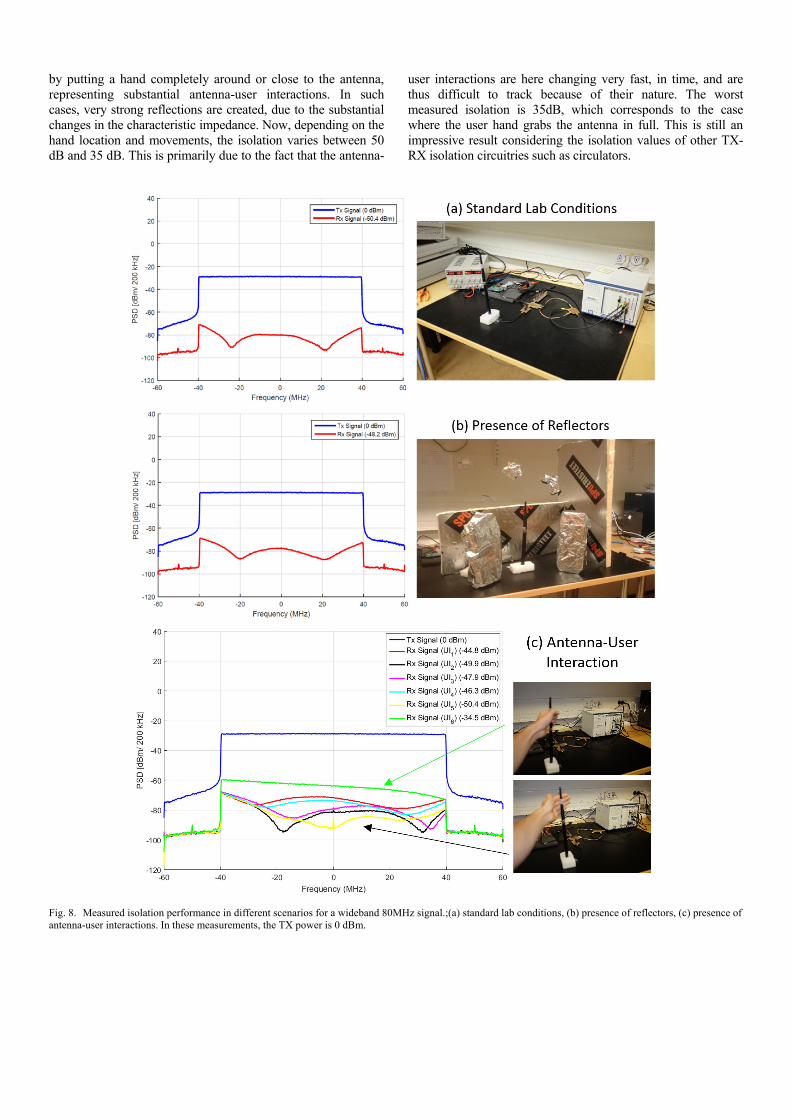
by putting a hand completely around or close to the antenna, representing substantial antenna-user interactions. In such cases, very strong reflections are created, due to the substantial changes in the characteristic impedance. Now, depending on the hand location and movements, the isolation varies between 50 dB and 35 dB. This is primarily due to the fact that the antenna-
user interactions are here changing very fast, in time, and are thus difficult to track because of their nature. The worst measured isolation is 35dB, which corresponds to the case where the user hand grabs the antenna in full. This is still an impressive result considering the isolation values of other TX-RX isolation circuitries such as circulators.
Fig. 8. Measured isolation performance in different scenarios for a wideband 80MHz signal.;(a) standard lab conditions, (b) presence of reflectors, (c) presence of antenna-user interactions. In these measurements, the TX power is 0 dBm.
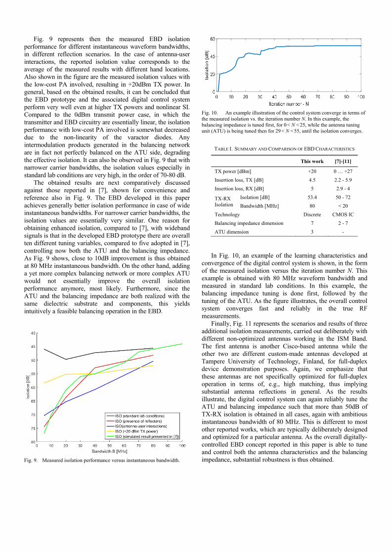
Fig. 9 represents then the measured EBD isolation performance for different instantaneous waveform bandwidths, in different reflection scenarios. In the case of antenna-user interactions, the reported isolation value corresponds to the average of the measured results with different hand locations. Also shown in the figure are the measured isolation values with the low-cost PA involved, resulting in +20dBm TX power. In general, based on the obtained results, it can be concluded that the EBD prototype and the associated digital control system perform very well even at higher TX powers and nonlinear SI. Compared to the 0dBm transmit power case, in which the transmitter and EBD circuitry are essentially linear, the isolation performance with low-cost PA involved is somewhat decreased due to the non-linearity of the varactor diodes. Any intermodulation products generated in the balancing network are in fact not perfectly balanced on the ATU side, degrading the effective isolation. It can also be observed in Fig. 9 that with narrower carrier bandwidths, the isolation values especially in standard lab conditions are very high, in the order of 70-80 dB.
The obtained results are next comparatively discussed against those reported in [7], shown for convenience and reference also in Fig. 9. The EBD developed in this paper achieves generally better isolation performance in case of wide instantaneous bandwidths. For narrower carrier bandwidths, the isolation values are essentially very similar. One reason for obtaining enhanced isolation, compared to [7], with wideband signals is that in the developed EBD prototype there are overall ten different tuning variables, compared to five adopted in [7], controlling now both the ATU and the balancing impedance. As Fig. 9 shows, close to 10dB improvement is thus obtained at 80 MHz instantaneous bandwidth. On the other hand, adding a yet more complex balancing network or more complex ATU would not essentially improve the overall isolation performance anymore, most likely. Furthermore, since the ATU and the balancing impedance are both realized with the same dielectric substrate and components, this yields intuitively a feasible balancing operation in the EBD.
Fig. 9. Measured isolation performance versus instantaneous bandwidth.
Fig. 10. An example illustration of the control system converge in terms of the measured isolation vs. the iteration number N. In this example, the balancing impedance is tuned first, for 0 < N < 25, while the antenna tuning unit (ATU) is being tuned then for 29 < N < 55, until the isolation converges.
TABLE I. SUMMARY AND COMPARISON OF EBD CHARACTERISTICS
This work [7]-[11]
TX power [dBm] +20 0 … +27
Insertion loss, TX [dB] 4.5 2.2 - 5.9
Insertion loss, RX [dB] 5 2.9 - 4
TX-RX Isolation
Isolation [dB] 53.4 50 - 72
Bandwidth [MHz] 80 < 20
Technology Discrete CMOS IC
Balancing impedance dimension 7 2 - 7
ATU dimension 3 -
In Fig. 10, an example of the learning characteristics and
convergence of the digital control system is shown, in the form of the measured isolation versus the iteration number N. This example is obtained with 80 MHz waveform bandwidth and measured in standard lab conditions. In this example, the balancing impedance tuning is done first, followed by the tuning of the ATU. As the figure illustrates, the overall control system converges fast and reliably in the true RF measurements.
Finally, Fig. 11 represents the scenarios and results of three additional isolation measurements, carried out deliberately with different non-optimized antennas working in the ISM Band. The first antenna is another Cisco-based antenna while the other two are different custom-made antennas developed at Tampere University of Technology, Finland, for full-duplex device demonstration purposes. Again, we emphasize that these antennas are not specifically optimized for full-duplex operation in terms of, e.g., high matching, thus implying substantial antenna reflections in general. As the results illustrate, the digital control system can again reliably tune the ATU and balancing impedance such that more than 50dB of TX-RX isolation is obtained in all cases, again with ambitious instantaneous bandwidth of 80 MHz. This is different to most other reported works, which are typically deliberately designed and optimized for a particular antenna. As the overall digitally-controlled EBD concept reported in this paper is able to tune and control both the antenna characteristics and the balancing impedance, substantial robustness is thus obtained.

Fig. 11. Measured isolation performance with different antennas, again using 80 MHz instantaneous bandwidth at 2.44 GHz center-frequency.
VI. CONCLUSIONS
This paper presented a novel digitally-controlled electrical balance duplexer (EBD) prototype facilitating inband full-duplex radio communications. The prototype integrates a self-adaptive or self-tracking automatic digital control system, tuning both the balancing impedance and the antenna tuning unit, for maintaining high isolation levels over time-varying reflection and antenna-user interaction scenarios. Complete demonstration system, control algorithms, implementation and RF measurements were reported, evidencing the developed EBD prototype to achieve up to 53 dB of isolation over an ambitious 80 MHz instantaneous bandwidth with high input power levels. The future work will focus on improving the TX and RX paths’ insertion losses as well as increasing the layout miniaturization.
ACKNOWLEDGMENT
The authors wish to thank Timo Huusari, Seong-youp Suh, Tae-Young Yang, Yang-seok Choi and Shilpa Talwar, all from Intel Corporation, for useful technical discussions, technical guidance and support, leading to these results.
REFERENCES
[1] A. Sabharwal, P. Schiniter, D. Guo, D.W. Bliss, S. Rangarajan and R. Wichman, “In-band full-dulex wireless: Challenges and opportunities,” IEEE J. Selected Areas Commun., vol 32, no. 9, pp. 1637-1652, Oct 2014.
[2] T. Huusari, Y.-S. Choi, P. Liikkanen, D. Korpi, S. Talwar, M. Valkama, “Wideband Self-Adaptive RF Cancellation Circuit for Full-Duplex Radio: Operating Principle and Measurements,” in Proc. IEEE Vehicular Technology Conference (VTC) Spring, 2015.
[3] M. Duarte, C. Dick, and A. Sabharwal, “Experiment-driven characterization of full-duplex wireless systems,” IEEE Transactions on Wireless Communications, vol. 11, no. 12, pp. 4296–4307, Dec. 2012.
[4] E. Everett, M. Duarte, C. Dick, and A. Sabharwal, “Empowering fullduplex wireless communication by exploiting directional diversity,” in Proc. 45th Asilomar Conference on Signals, Systems and Computers, Nov. 2011, p. 2002-2006.
[5] J. I. Choi, M. Jain, K. Srinivasan, P. Levis, and S. Katti, “Achieving single channel, full duplex wireless communication,” in Proc. 2010, International Conf. Mobile Comput. Netw., pp. 1–12.
[6] D. Bharadia, E. McMilin, and S. Katti, “Full duplex radios,” in Proc SIGCOMM’13, pp. 375–386, Aug. 2013.
[7] L. Laughlin, M.A. Beach, K.A. Morris and J. Hainey, “Electrical Balance Isolation for Flexible Duplexing in 5G Mobile Devices,” IEEE Communication Workshop ICCW, Jun. 2015.
[8] S.H. Abdelhalem, P.S. Gudem, L.E. Larson, “Hybrid Transformer-Based Tunable Differential Duplexer in a 90-nm CMOS Process,” IEEE Trans. Microwave Theory Tech., vol 61, no. 3, pp.1316-1326, Feb. 2013.
[9] M. Mikhael, B.V. Liempd, J. Craninckx, R. Guindi, B. Debaillie, “An In-Band Full-Duplex Transceiver Prototype with an In-System Automated Tuning for RF Self-Interference Cancellation,” IEEE Int. Conf. 5G for Ubiquitous Connectivity, Nov. 2014.
[10] S.H. Abdelhalem, P.S. Gundem, L.E. Larson, “Hybrid Transformer-Based Tunable Integrated Duplexer with Antenna Impedance Tracking Loop,” IEEE Custom Integrated Circuits Conf. (CICC), Sept. 2013.
[11] L. Laughlin, M.A. Beach, K.A. Morris, J.L. Haine, “Optimum Single Antenna Full Duplex using Hybrid Junctions,” IEEE J. Selected Areas Commun., vol 32, no. 9, pp1653-1661, Sept 2014.
[12] M. Mikherman, H. Darabi, A. Abidi, “A Tunable Integrated Duplexer with 50 dB Isolation in 40nm CMOS,” IEEE International Solid-State Circuits Conference, 2009.
[13] L. Laughlin, M.A. Beach, K.A. Morris, J.L. Haine, “Electrical Balancec Duplexing for Small Form Factor Realization of In-Band Full Duplex,” IEEE Communication Magazine, May 2015.
[14] A. Kumar, S. Aniruddhan, R.K. Ganti,, “Directional Coupler, with High Isolation Bandwidth using Electrical Balance,” IEEE Microwave Symposium (IMS), 2014.
[15] M. Thompson, J.K. Fidler, “Determination of the Impedance Matching Domain of Impedance Matching Networks,” IEEE Transaction on Circuits and System, vol 51, no. 10, Oct 2014.
[16] H. Darabi, A. Mirzaei, M. Mikhemar, “Highly Integrated and Tunable RF Front Ends for Reconfigurable Multiband Transceiver: A Tutorial,” IEEE Transaction on Circuits and Systems, vol 58, no. 9, Sept 2011
[17] J. de Mingo, A. Valdovinos, A. Crespo, D. Navarro, P. Garcìa, “An RF Electronically Controlled Impedance Tuning Network Design and its Application to an Antenna Input Impedeance Automatic Matching System,” IEEE Trans.Microwave Theory Tech., vol. 52, no. 2, 2004.
[18] C. Hoarau, P.-E. Bially, J.-D. Arnould, P. Ferrari, P. Xavier, “An RF Tunable impedance Matching Network with a Complete Design and Measurement Methodology,” IEEE European Microwave Conf., Oct 2007.
[19] A.C. Carusone, D.A. Johns, “Analog Filter Adaptation using a Dithered Linear Search Algorithm,” IEEE Trans. Circuits Syst., vol. 4, 2002.
[20] W.H. Press, S.A. Teukolsky, W.T. Vetterling, B.P. Flannery, “Downhill Simplex Method in Multidimensions,” Numerical Recepies in C, chapter 10, section 10.4, 1992.
[21] L. Laughlin, M.A. Beach, K.A. Morris, J. Haine, “Performance Variation in Elecrical Balance Duplexers due to User Interaction,” in Proc. IEEE PIMRC, Sept. 2014.