DIGITALAlphaServer400...
34
DIGITAL AlphaServer 400 Firmware Update Procedures Digital Equipment Corporation Maynard, Massachusetts
Transcript of DIGITALAlphaServer400...
DIGITAL AlphaServer 400Firmware Update Procedures
Digital Equipment CorporationMaynard, Massachusetts

First Printing, March 1996Revised, May 1996Revised, September 1996Revised, December 1996Revised, March 1997Revised, October 1997Revised, January 1998Revised, June 1998Revised, September 1998Revised,March 1999
Digital Equipment Corporation makes no representations that the use of its products in themanner described in this publication will not infringe on existing or future patent rights, nor dothe descriptions contained in this publication imply the granting of licenses to make, use, or sellequipment or software in accordance with the description.
Possession, use, or copying of the software described in this publication is authorized only pursuantto a valid written license from DIGITAL or an authorized sublicensor.
Copyright © Digital Equipment Corporation, 1996, 1997, 1998, 1999. All Rights Reserved.
COMPAQ, the Compaq logo and the Digital logo Registered in U.S. Patent and Trademark Office.
Alpha, AlphaServer, Bookreader, DEC, DECchip, DECpc, DECwindows, DEC VET, DIGITAL,InfoServer, OpenVMS, RRD43, RZ, TURBOchannel, ULTRIX, VAX, VAX DOCUMENT, and VMS aretrademarks of Compaq Computer Corporation.
PostScript is a registered trademark of Adobe Systems, Inc. Windows NT is a trademark ofMicrosoft, Inc. Motif is a registered trademark of the Open Software Foundation, Inc., licensedby Digital. UNIX is a registered trademark in the United States and other countries licensedexclusively through X/Open Company Ltd.
All other trademarks and registered trademarks are the property of their respective holders.
FCC NOTICE: The equipment described in this manual generates, uses, and may emit radiofrequency energy. The equipment has been type tested and found to comply with the limits fora Class A computing device pursuant to Subpart J of Part 15 of FCC Rules, which are designedto provide reasonable protection against such radio frequency interference when operated in acommercial environment. Operation of this equipment in a residential area may cause interference,in which case the user at his own expense may be required to take measures to correct theinterference.
This document was prepared using VAX DOCUMENT Version 2.1.
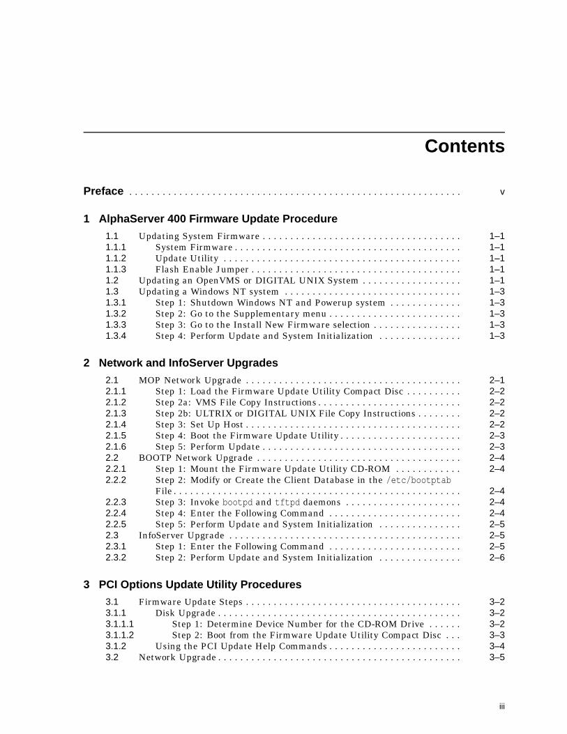
Contents
Preface . . . . . . . . . . . . . . . . . . . . . . . . . . . . . . . . . . . . . . . . . . . . . . . . . . . . . . . . . . . . v
1 AlphaServer 400 Firmware Update Procedure
1.1 Updating System Firmware . . . . . . . . . . . . . . . . . . . . . . . . . . . . . . . . . . . . 1–11.1.1 System Firmware . . . . . . . . . . . . . . . . . . . . . . . . . . . . . . . . . . . . . . . . . 1–11.1.2 Update Utility . . . . . . . . . . . . . . . . . . . . . . . . . . . . . . . . . . . . . . . . . . . 1–11.1.3 Flash Enable Jumper . . . . . . . . . . . . . . . . . . . . . . . . . . . . . . . . . . . . . . 1–11.2 Updating an OpenVMS or DIGITAL UNIX System . . . . . . . . . . . . . . . . . . 1–11.3 Updating a Windows NT system . . . . . . . . . . . . . . . . . . . . . . . . . . . . . . . . 1–31.3.1 Step 1: Shutdown Windows NT and Powerup system . . . . . . . . . . . . . 1–31.3.2 Step 2: Go to the Supplementary menu . . . . . . . . . . . . . . . . . . . . . . . . 1–31.3.3 Step 3: Go to the Install New Firmware selection . . . . . . . . . . . . . . . . 1–31.3.4 Step 4: Perform Update and System Initialization . . . . . . . . . . . . . . . 1–3
2 Network and InfoServer Upgrades
2.1 MOP Network Upgrade . . . . . . . . . . . . . . . . . . . . . . . . . . . . . . . . . . . . . . . 2–12.1.1 Step 1: Load the Firmware Update Utility Compact Disc . . . . . . . . . . 2–22.1.2 Step 2a: VMS File Copy Instructions . . . . . . . . . . . . . . . . . . . . . . . . . . 2–22.1.3 Step 2b: ULTRIX or DIGITAL UNIX File Copy Instructions . . . . . . . . 2–22.1.4 Step 3: Set Up Host . . . . . . . . . . . . . . . . . . . . . . . . . . . . . . . . . . . . . . . 2–22.1.5 Step 4: Boot the Firmware Update Utility . . . . . . . . . . . . . . . . . . . . . . 2–32.1.6 Step 5: Perform Update . . . . . . . . . . . . . . . . . . . . . . . . . . . . . . . . . . . . 2–32.2 BOOTP Network Upgrade . . . . . . . . . . . . . . . . . . . . . . . . . . . . . . . . . . . . . 2–42.2.1 Step 1: Mount the Firmware Update Utility CD-ROM . . . . . . . . . . . . 2–42.2.2 Step 2: Modify or Create the Client Database in the /etc/bootptab
File . . . . . . . . . . . . . . . . . . . . . . . . . . . . . . . . . . . . . . . . . . . . . . . . . . . . 2–42.2.3 Step 3: Invoke bootpd and tftpd daemons . . . . . . . . . . . . . . . . . . . . . 2–42.2.4 Step 4: Enter the Following Command . . . . . . . . . . . . . . . . . . . . . . . . 2–42.2.5 Step 5: Perform Update and System Initialization . . . . . . . . . . . . . . . 2–52.3 InfoServer Upgrade . . . . . . . . . . . . . . . . . . . . . . . . . . . . . . . . . . . . . . . . . . 2–52.3.1 Step 1: Enter the Following Command . . . . . . . . . . . . . . . . . . . . . . . . 2–52.3.2 Step 2: Perform Update and System Initialization . . . . . . . . . . . . . . . 2–6
3 PCI Options Update Utility Procedures
3.1 Firmware Update Steps . . . . . . . . . . . . . . . . . . . . . . . . . . . . . . . . . . . . . . . 3–23.1.1 Disk Upgrade . . . . . . . . . . . . . . . . . . . . . . . . . . . . . . . . . . . . . . . . . . . . 3–23.1.1.1 Step 1: Determine Device Number for the CD-ROM Drive . . . . . . 3–23.1.1.2 Step 2: Boot from the Firmware Update Utility Compact Disc . . . 3–33.1.2 Using the PCI Update Help Commands . . . . . . . . . . . . . . . . . . . . . . . . 3–43.2 Network Upgrade . . . . . . . . . . . . . . . . . . . . . . . . . . . . . . . . . . . . . . . . . . . . 3–5
iii
4 AlphaServer 400 Series Firmware Information
4.1 New Features . . . . . . . . . . . . . . . . . . . . . . . . . . . . . . . . . . . . . . . . . . . . . . . 4–14.1.1 Identifying your AlphaServer system’s current ISA bus
configuration . . . . . . . . . . . . . . . . . . . . . . . . . . . . . . . . . . . . . . . . . . . . 4–14.1.2 Installing a Turbo Plus when there are no bus conflicts . . . . . . . . . . . . 4–34.1.3 Installing a Turbo Plus board where there are conflicts . . . . . . . . . . . . 4–34.1.4 Help Screens . . . . . . . . . . . . . . . . . . . . . . . . . . . . . . . . . . . . . . . . . . . . 4–54.1.5 EWRK3_CONFIG Command Information . . . . . . . . . . . . . . . . . . . . . . 4–54.1.6 ISA Configuration Utility . . . . . . . . . . . . . . . . . . . . . . . . . . . . . . . . . . . 4–74.2 SRM Firmware Limitations . . . . . . . . . . . . . . . . . . . . . . . . . . . . . . . . . . . . 4–8
Figures
3–1 The show device Display . . . . . . . . . . . . . . . . . . . . . . . . . . . . . . . . . . . 3–2
Tables
1 DIGITAL AlphaServer 400 . . . . . . . . . . . . . . . . . . . . . . . . . . . . . . . . . vi2 DIGITAL AlphaServer 400 . . . . . . . . . . . . . . . . . . . . . . . . . . . . . . . . . vi1–1 Update Firmware from the SRM Console . . . . . . . . . . . . . . . . . . . . . . 1–22–1 Updating System Firmware . . . . . . . . . . . . . . . . . . . . . . . . . . . . . . . . . 2–13–1 Procedure for Updating System Firmware (Method 1) . . . . . . . . . . . . 3–2
iv

Preface
Purpose of This GuideThis guide is intended for all managers of the AlphaServer 400 series of systems.
This guide describes how to update the system’s firmware using the loadableFirmware Update Utility.
Purpose and Responsibility of the Loadable Firmware Update UtilityThe Loadable Firmware Update Utility has been developed to allow the ownersof existing and new DIGITAL AlphaServer 400 systems to maintain firmware ontheir systems. Firmware provides a number of basic functions on your system,including operating system bootstrap, configuration identification, testing andsome basic input/output operations.
To assist the owner, who’s responsibility it is to perform the update, a simpleand user friendly interface is provided as part of the Loadable FirmwareUpdate Utility. This program should be executed as directed by the releasenotes whenever new software is purchased or as directed by Digital EquipmentCorporation.
ConventionsThe following conventions are used in this guide:
Convention Description
RZ2x RZ2x refers to any of the RZ-series fixed disk drives, includingthe RZ24L, RZ25, and RZ26.
Return A key name in a box indicates that you press a named key onthe keyboard.
Ctrl/x A sequence such as Ctrl/x indicates that you must hold downthe key labeled Ctrl while you press another key.
show config This typeface denotes commands and command output.Commands are not case-sensitive except where specificallyindicated.
italics Italicized letters indicate a variable value that you mustprovide. For example,
>>> set variable Return
Caution Cautions provide information to prevent damage to equipmentor software.
Warning Warnings contain information to prevent personal injury.
v
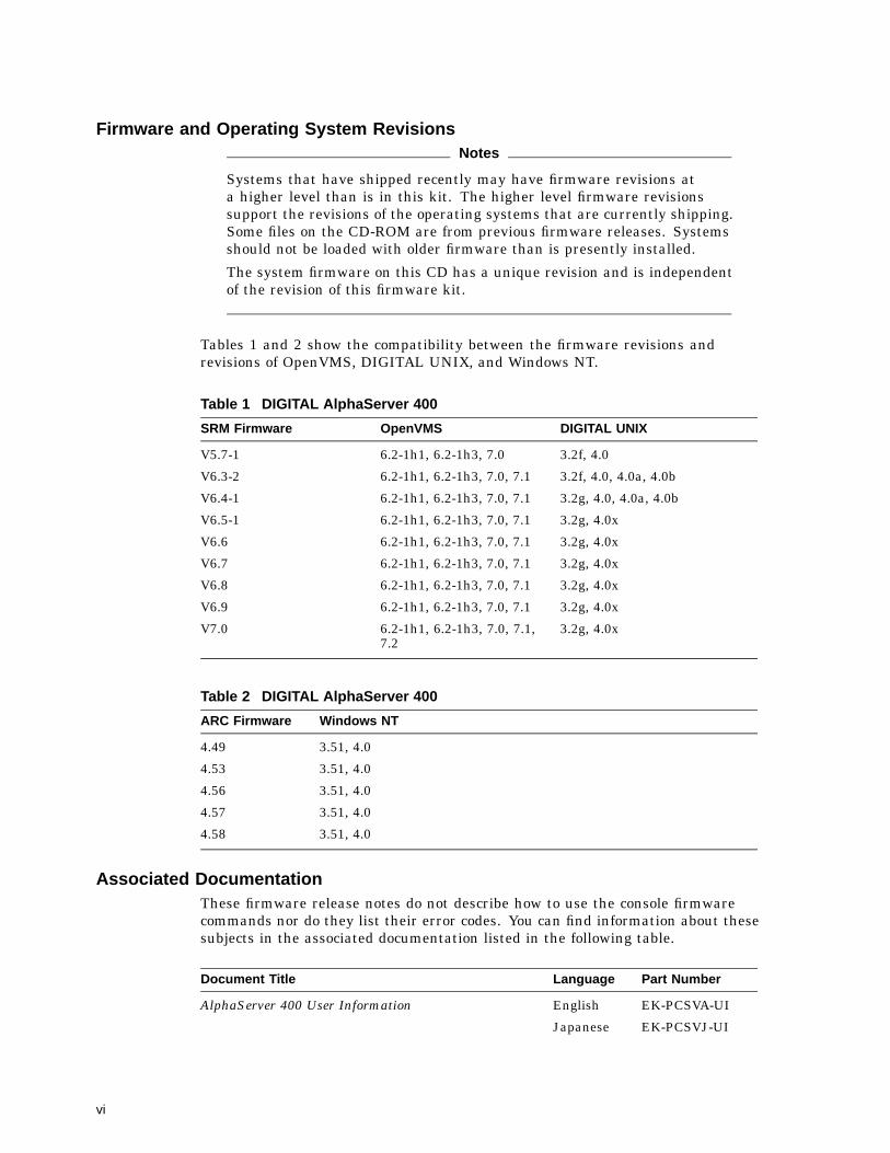
Firmware and Operating System RevisionsNotes
Systems that have shipped recently may have firmware revisions ata higher level than is in this kit. The higher level firmware revisionssupport the revisions of the operating systems that are currently shipping.Some files on the CD-ROM are from previous firmware releases. Systemsshould not be loaded with older firmware than is presently installed.
The system firmware on this CD has a unique revision and is independentof the revision of this firmware kit.
Tables 1 and 2 show the compatibility between the firmware revisions andrevisions of OpenVMS, DIGITAL UNIX, and Windows NT.
Table 1 DIGITAL AlphaServer 400
SRM Firmware OpenVMS DIGITAL UNIX
V5.7-1 6.2-1h1, 6.2-1h3, 7.0 3.2f, 4.0
V6.3-2 6.2-1h1, 6.2-1h3, 7.0, 7.1 3.2f, 4.0, 4.0a, 4.0b
V6.4-1 6.2-1h1, 6.2-1h3, 7.0, 7.1 3.2g, 4.0, 4.0a, 4.0b
V6.5-1 6.2-1h1, 6.2-1h3, 7.0, 7.1 3.2g, 4.0x
V6.6 6.2-1h1, 6.2-1h3, 7.0, 7.1 3.2g, 4.0x
V6.7 6.2-1h1, 6.2-1h3, 7.0, 7.1 3.2g, 4.0x
V6.8 6.2-1h1, 6.2-1h3, 7.0, 7.1 3.2g, 4.0x
V6.9 6.2-1h1, 6.2-1h3, 7.0, 7.1 3.2g, 4.0x
V7.0 6.2-1h1, 6.2-1h3, 7.0, 7.1,7.2
3.2g, 4.0x
Table 2 DIGITAL AlphaServer 400
ARC Firmware Windows NT
4.49 3.51, 4.0
4.53 3.51, 4.0
4.56 3.51, 4.0
4.57 3.51, 4.0
4.58 3.51, 4.0
Associated DocumentationThese firmware release notes do not describe how to use the console firmwarecommands nor do they list their error codes. You can find information about thesesubjects in the associated documentation listed in the following table.
Document Title Language Part Number
AlphaServer 400 User Information English EK-PCSVA-UI
Japanese EK-PCSVJ-UI
vi

Document Title Language Part Number
AlphaServer 400 Upgrade Information English EK-ALPH4-UP
AlphaServer 400 Installation Information English EK-PCSVA-II
Reader CommentsDIGITAL welcomes your comments on this or any other manual. You can sendyour comments to DIGITAL at the following address:
Digital Equipment CorporationShared Engineering Services129 Parker StreetPKO3-2/E30Maynard, MA 01754-2199
vii


1AlphaServer 400 Firmware Update Procedure
This chapter explains how to update the AlphaServer 400 firmware. Topics areas follows:
• Upgrading DIGITAL UNIX or OpenVMS system from a CD
• Upgrading a Windows NT system from a CD
1.1 Updating System Firmware1.1.1 System Firmware
The DIGITAL AlphaServer 400 system contains four flash ROMs, two withARC console firmware for the Windows NT operating system and two with SRMconsole firmware for the DIGITAL UNIX and OpenVMS operating systems. SeeTable 1 and Table 2 for compatible firmware and operating system versions.
1.1.2 Update UtilityUse the update utility to update your ARC and SRM firmware. The update utilitycontains three images: the update utility itself, the SRM image, and the ARCimage.
1.1.3 Flash Enable JumperBefore you can update your system firmware, the flash ROM enable jumper mustbe in the write-enabled position. This is the default position. See the DIGITALAlphaServer 400 User Information Documents for details.
1.2 Updating an OpenVMS or DIGITAL UNIX SystemThe procedure to update firmware using the Alpha Firmware CD from the SRM console is shownbelow.
AlphaServer 400 Firmware Update Procedure 1–1

Table 1–1 Update Firmware from the SRM Console
Update Steps
Insert Alpha Firmware CDinto CD-ROM drive
>>> show device Find the CD-ROM device ID e.g dka400
Boot the Alpha Firmware CD >>> Boot dka400 Boot code determines AlphaStation typethen displays the firmware update file anda Bootfile: prompt.
Press the enter-key after theBootfile prompt
Bootfile: Use the default firmware update file
Using the serial port typeupdate at the Update utilityprompt
APU-> update Update console and option firmware
Using the Graphic Terminalselect Update using thecursor arrow keys
APU-> update Update console and option firmware
Type exit after the firmwareupdate is complate
APU->exit Exit the APU and initialize the system
Example:
>>> show device...... dka400.1.0.1.0 DKA400 RRD43 1084...>>> boot dka400(boot dka400.1.0.1.0)block 0 of dka400.1.0.1.0 is a valid boot blockreading 989 blocks from dka400.5.0.1000.0bootstrap code read inbase = 156000, image_start = 0, image_bytes = 7ba00initializing HWRPB at 2000initializing page table at 148000initializing machine statesetting affinity to the primary CPUjumping to bootstrap code
[Release notes are displayed]Bootfile: [press enter-key]
*** AlphaServer 400 4/233 -- Firmware Update V7.0 ***
For more information type: HELP <Topic> or ? <Topic>
1–2 AlphaServer 400 Firmware Update Procedure
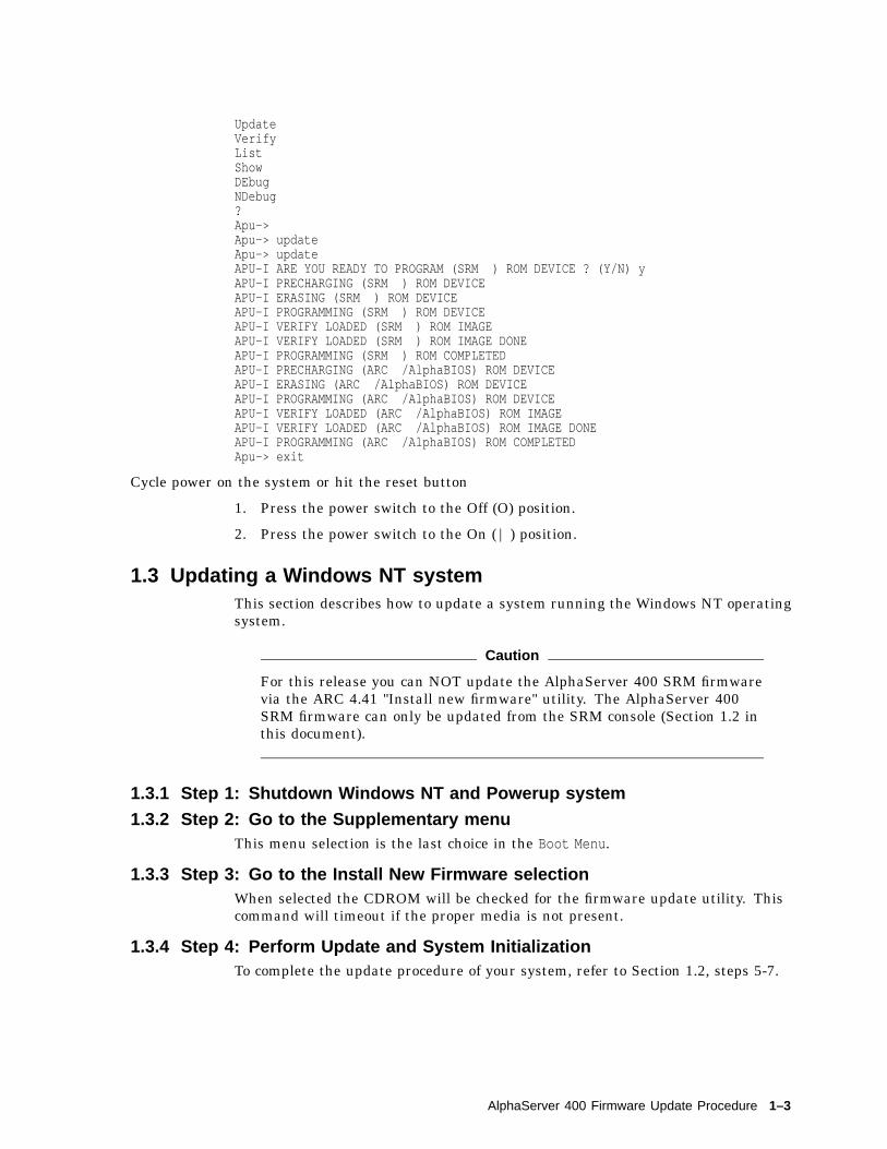
UpdateVerifyListShowDEbugNDebug?Apu->Apu-> updateApu-> updateAPU-I ARE YOU READY TO PROGRAM (SRM ) ROM DEVICE ? (Y/N) yAPU-I PRECHARGING (SRM ) ROM DEVICEAPU-I ERASING (SRM ) ROM DEVICEAPU-I PROGRAMMING (SRM ) ROM DEVICEAPU-I VERIFY LOADED (SRM ) ROM IMAGEAPU-I VERIFY LOADED (SRM ) ROM IMAGE DONEAPU-I PROGRAMMING (SRM ) ROM COMPLETEDAPU-I PRECHARGING (ARC /AlphaBIOS) ROM DEVICEAPU-I ERASING (ARC /AlphaBIOS) ROM DEVICEAPU-I PROGRAMMING (ARC /AlphaBIOS) ROM DEVICEAPU-I VERIFY LOADED (ARC /AlphaBIOS) ROM IMAGEAPU-I VERIFY LOADED (ARC /AlphaBIOS) ROM IMAGE DONEAPU-I PROGRAMMING (ARC /AlphaBIOS) ROM COMPLETEDApu-> exit
Cycle power on the system or hit the reset button
1. Press the power switch to the Off (O) position.
2. Press the power switch to the On ( | ) position.
1.3 Updating a Windows NT systemThis section describes how to update a system running the Windows NT operatingsystem.
Caution
For this release you can NOT update the AlphaServer 400 SRM firmwarevia the ARC 4.41 "Install new firmware" utility. The AlphaServer 400SRM firmware can only be updated from the SRM console (Section 1.2 inthis document).
1.3.1 Step 1: Shutdown Windows NT and Powerup system
1.3.2 Step 2: Go to the Supplementary menuThis menu selection is the last choice in the Boot Menu.
1.3.3 Step 3: Go to the Install New Firmware selectionWhen selected the CDROM will be checked for the firmware update utility. Thiscommand will timeout if the proper media is not present.
1.3.4 Step 4: Perform Update and System InitializationTo complete the update procedure of your system, refer to Section 1.2, steps 5-7.
AlphaServer 400 Firmware Update Procedure 1–3


2Network and InfoServer Upgrades
This chapter explains how to perform network updates:
• MOP network upgrades
• BOOTP network upgrades
• InfoServer upgrades
2.1 MOP Network UpgradeNote
You can use a DIGITAL UNIX system to copy the file from the FirmwareUpdate Utility CD-ROM, but MOP is not supported under DIGITALUNIX.
The AlphaServer 400 series of systems to be updated (target system) must bepowered on and at the console prompt (>>>).
Table 2–1 lists the steps required to update the firmware on yourAlphaServer 400 system from the network.
Table 2–1 Updating System Firmware
Step Description
1 Place the Firmware Update Utility compact disc into the CD drive on the hostsystem.
2 If the host is a VMS, ULTRIX, or DIGITAL UNIX system, copy the update filefrom the Firmware Update Utility compact disc.
3 Set up the host system.
4 Enter a network boot command from the target system.
5 Refer to Section 1.2, steps 5-7 to complete update procedure.
Network and InfoServer Upgrades 2–1

2.1.1 Step 1: Load the Firmware Update Utility Compact Disc
1. Remove any compact disc that may already be loaded into the CD drive.
2. Load the Firmware Update compact disc into the drive.
2.1.2 Step 2a: VMS File Copy InstructionsIf your host system is VMS, copy the file from the Firmware Update Utilitycompact disc by entering the following commands at the VMS $ prompt.
$ mount dka400: update_v54
Use the following path/filename in order to update anAlphaServer 400:
$ copy dka400:[SYS0.SYSEXE]ASV400_V7_0.sys mom$load:
2.1.3 Step 2b: ULTRIX or DIGITAL UNIX File Copy InstructionsIf your host system is ULTRIX or DIGITAL UNIX, copy the file from theFirmware Update Utility compact disc by entering the following commandsat the ULTRIX or DIGITAL UNIX # prompt.
# mount -rt cdfs -o noversion /dev/rz4c /mnt
Use the following path/filename in order to update anAlphaServer 400:
# cp /mnt/ALPHASV400/ASV400_V7_0.SYS /usr/lib/mop/filename
2.1.4 Step 3: Set Up HostExecute the following when updating an AlphaServer 400 using a VMS host. Youmust use NCP to define the characteristics of the host and target system. Youwill need OPER privileges.
$ MCR NCP set circ CIRC_NAME state off$ MCR NCP set circ CIRC_NAME serv enabled$ MCR NCP set circ CIRC_NAME state on
Note
CIRC_NAME is the logical name of the circuit used by the network.
Execute the following only when updating an AlphaServer 400 series systemusing an ULTRIX host. Please note that MOP is not supported under DigitalUNIX.
Make sure the mop_mom process is running. If ps aux|grep mop does not show amop_mom process, then you must start one by issuing the following command as asuperuser:
# mop_mom
2–2 Network and InfoServer Upgrades

2.1.5 Step 4: Boot the Firmware Update UtilityTo start the Firmware Update Utility, enter the boot command at the consoleprompt on the target system. The following command starts a boot process:
>>> boot ewa0 -fi filename
Note
The filename must be entered exactly as displayed by the ULTRIX host.
After the boot process completes, the Firmware Update Utility menu is displayed.Note the Update Utility prompt (APU->). The following is an example of bootingthe AlphaServer 400 update utility.
bootstrap code read inbase = 11e000, image_start = 0, image_bytes = ea800initializing HWRPB at 2000initializing page table at 110000initializing machine statesetting affinity to the primary CPUjumping to bootstrap codeff.fe.fd.fc.fb.fa.f9.f8.f7.f6.f5.ef.df.ee.ed.ec.f4.eb.....ea.e9.e8.e7.e6.e5.7.0-1, built on May 15 1998 at 15:05:15>>>Execute Update SequenceUpdate Script Complete(boot pmem:180000 -file armen2.sys -flags 0,0)bootstrap code read inbase = 180000, image_start = 0, image_bytes = 800000initializing HWRPB at 2000initializing page table at 7ee000initializing machine statesetting affinity to the primary CPUjumping to bootstrap code
*** AlphaServer 400 4/233 -- Firmware Update CD_54 ***
For more information type: HELP <Topic> or ? <Topic>
UpdateVerifyListShowDEbugNDebug?
2.1.6 Step 5: Perform UpdateTo complete the update procedure of your system, refer to Section 1.2, steps 5-7.
Network and InfoServer Upgrades 2–3

2.2 BOOTP Network Upgrade
2.2.1 Step 1: Mount the Firmware Update Utility CD-ROM
# mount -rt cdfs -o noversion /dev/rz4c /mnt
2.2.2 Step 2: Modify or Create the Client Database in the /etc/bootptab File
<host_name>:ht:<hw_type>:ha=<hw_address>:bf=ASV400_V7_0.EXE:ip=<ip_address>
where:
• host_name is the system name in /etc/hosts.
• hw_type is the hardware type. Proteon is ht = 4. Ethernet is ht = 1. Regulartoken-ring (IEEE 802) is ht = 6.
• hw_address is the hardware address: use the console command show device.
• ip_address is the corresponding Internet protocol address of the system namein /etc/hosts.
The following is an example of a bootptab file:
bigsox:ht=1:ha=08002b236423:bf=/mnt/ALPHASV400/ASV400_V7_0.EXE;1:ip=16.182.0.87
2.2.3 Step 3: Invoke bootpd and tftpd daemons
• Modify the /etc/inetd.conf file. Uncommon the tftp and bootps process. Itshould look like the following example:
tftp dgram udp wait root /usr/sbin/tftpd tftpd /mntbootps dgram upd wait root /usr/sbin/bootpd bootpd
• Find the process /usr/sbin/inetd daemon:
# ps aux | grep ine# kill process#
• Restart the inetd daemon:
# /usr/sbin/inetd
Note
The bootpd and tftp daemon will be removed if the system is rebooted.Refer to the manual pages: bootpd(8) or tftpd(8) for more information.
2.2.4 Step 4: Enter the Following CommandPrior to entering the >>> bootp ewao command, the user must perform the genericbootp setup as described in Section 4.2, SRM Firmware Limitations.
2–4 Network and InfoServer Upgrades

2.2.5 Step 5: Perform Update and System InitializationTo complete the update procedure of your system, refer to Section 1.2, steps 5-7.
2.3 InfoServer UpgradeBe certain to:
• Insert the compact disc into a CD-ROM reader that is connected to theInfoServer.
• The InfoServer kernel must be at a minimum revision of 2.2 and MOP mustbe enabled on the InfoServer.
2.3.1 Step 1: Enter the Following CommandTo perform an upgrade using the InfoServer, enter the following command line.The filename must be in uppercase.
To update an AlphaServer 400 enter the following:
>>> boot ewa0 -fi ASV400_V7_0
The following is an example of updating an AlphaServer 400:
bootstrap code read inbase = 11e000, image_start = 0, image_bytes = ea800initializing HWRPB at 2000initializing page table at 110000initializing machine statesetting affinity to the primary CPUjumping to bootstrap codeff.fe.fd.fc.fb.fa.f9.f8.f7.f6.f5.ef.df.ee.ed.ec.f4.eb.....ea.e9.e8.e7.e6.e5.7.0-1, built on May 15 1998 at 15:05:15>>>Execute Update SequenceUpdate Script Complete(boot pmem:180000 -file armen2.sys -flags 0,0)bootstrap code read inbase = 180000, image_start = 0, image_bytes = 800000initializing HWRPB at 2000initializing page table at 7ee000initializing machine statesetting affinity to the primary CPUjumping to bootstrap code
*** AlphaServer 400 4/233 -- Firmware Update CD_52 ***
For more information type: HELP <Topic> or ? <Topic>
UpdateVerifyListShowDEbugNDebug?Apu->
Network and InfoServer Upgrades 2–5
2.3.2 Step 2: Perform Update and System InitializationTo complete the update procedure of your system, refer to Section 1.2, steps 5-7.
2–6 Network and InfoServer Upgrades

3PCI Options Update Utility Procedures
This chapter explains how to update the firmware in PCI options that containflash ROMs. The topics are as follows:
• Updating the PCI option firmware
• Using the PCI Update help commands
Note
Some modules require an update jumper be in place before the flash ROMcan be updated. Refer to the installation procedure supplied with theoption.
Caution
It is important that you follow the steps for updating the system firmwarecarefully. Failure to perform the update procedure correctly may renderyour option inoperable.
PCI Options Update Utility Procedures 3–1

3.1 Firmware Update StepsYour option can be updated using two methods:
1. Booting the Update Utility from a CD-ROM drive
2. Booting the Update Utility from the network
If you plan to use the network procedure, go to Section 3.2.
3.1.1 Disk UpgradeTable 3–1 indicates the steps required to update the firmware on your PCIoption.
Table 3–1 Procedure for Updating System Firmware (Method 1)
Step Description
1 Use the show device command to determine the device number of the compactdisc drive on your system.
2 Boot your system from the Firmware Update Utility disc.
3.1.1.1 Step 1: Determine Device Number for the CD-ROM DriveTo run the Firmware Update Utility, you need to boot your system from thecompact disc drive and the system must be in console mode. To do this, you needthe device number of the disc drive.
To obtain the device number of the CD-ROM drive, enter a show device commandat the console prompt and press the Return key as shown in Figure 3–1. A list ofall device numbers on your system is displayed in the BOOTDEV column. Checkthe DEVNAM column for the device names.
Figure 3–1 The show device Display
>>> show device Return
BOOTDEV ADDR DEVTYPE NUMBYTES RM/FX WP DEVNAM REV------- ---- ------- -------- ----- -- ------ ---ESA0 08-00-2B-12-00-9CDKA100 A/1/0 DISK 426.25MB FX RZ25 0700DKA400 A/4/0 RODISK ..... RM WP RRD42 4.3d..HostID.. A/7 INITRDKB400 B/4/0 RODISK ..... RM WP RRD43 0064..HostID.. B/7 INITR
In Figure 3–1, the device number of the RRD42 drive is DKA400 and the RRD43drive is DKB400. You would use either device number to boot your system. Formore information about the show device command, see the owner’s guide for yoursystem.
3–2 PCI Options Update Utility Procedures

3.1.1.2 Step 2: Boot from the Firmware Update Utility Compact DiscTo start the Firmware Update Utility, type the boot command, flags, and devicenumber, then press the Return key.
You will see a display similar to the following as your system starts the bootprocess:
>>> boot -fl 0,A0 dka400 Return
INIT-S-CPU...AUDIT_CHECKSUM_GOODAUDIT_LOAD_BEGINSAUDIT_LOAD_DONE
The Firmware Update Utility will then prompt you for the name of the boot filethat you want to boot, as follows:
BOOTFILE:
Enter the file name of the Firmware Update Utility as follows:
BOOTFILE: [dir]filename Return
The following is the PCI update directory and filename on the CD-ROM for theAlphaServer 400:
[ALPHASV400]ASV400_PCI_V1_4.EXE
Note
The file name of the Firmware Update Utility will change with eachnew release. Refer to the documentation that comes with your FirmwareUpdate Utility compact disc for the correct file name.
The following information is displayed after the boot file is loaded:
*** PCI Loadable Firmware Update Utility V1.4 ***------------------------------------------------------------Function Description------------------------------------------------------------
Display Displays the system’s configuration table.Exit Done exit LFU (reset.)List Lists the device, revision, firmware name,
and update revision.Update Replaces current firmware with loadable data image.Verify Compares loadable and hardware images.? or Help Scrolls this function table.--------------------------------------------------------------
UPD>
PCI Options Update Utility Procedures 3–3
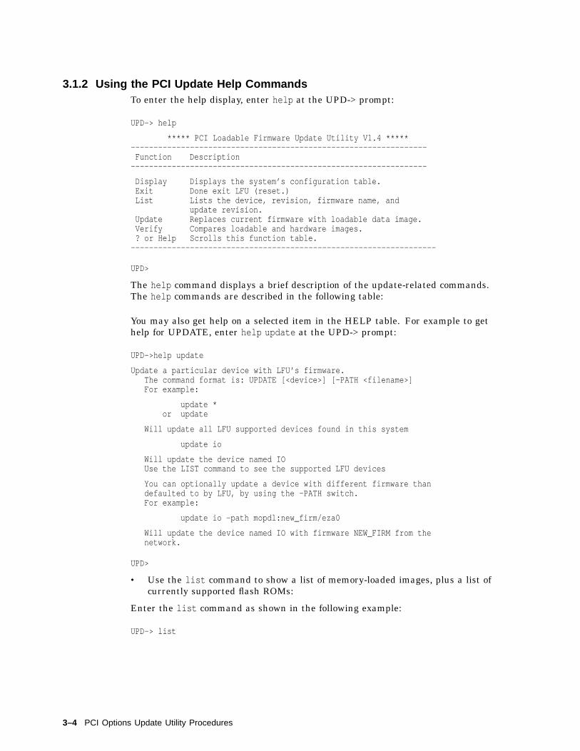
3.1.2 Using the PCI Update Help CommandsTo enter the help display, enter help at the UPD-> prompt:
UPD-> help
***** PCI Loadable Firmware Update Utility V1.4 *****-----------------------------------------------------------------Function Description-----------------------------------------------------------------
Display Displays the system’s configuration table.Exit Done exit LFU (reset.)List Lists the device, revision, firmware name, and
update revision.Update Replaces current firmware with loadable data image.Verify Compares loadable and hardware images.? or Help Scrolls this function table.-------------------------------------------------------------------
UPD>
The help command displays a brief description of the update-related commands.The help commands are described in the following table:
You may also get help on a selected item in the HELP table. For example to gethelp for UPDATE, enter help update at the UPD-> prompt:
UPD->help update
Update a particular device with LFU’s firmware.The command format is: UPDATE [<device>] [-PATH <filename>]For example:
update *or update
Will update all LFU supported devices found in this system
update io
Will update the device named IOUse the LIST command to see the supported LFU devices
You can optionally update a device with different firmware thandefaulted to by LFU, by using the -PATH switch.For example:
update io -path mopdl:new_firm/eza0
Will update the device named IO with firmware NEW_FIRM from thenetwork.
UPD>
• Use the list command to show a list of memory-loaded images, plus a list ofcurrently supported flash ROMs:
Enter the list command as shown in the following example:
UPD-> list
3–4 PCI Options Update Utility Procedures

The following is a sample response:
Device Current Revision Filename Update Revision
fwa0 2.46 dfpaa_fw 2.46
pka0 A09 kzpsa_fw A10
Note
Currently there are only two PCI devices supported by this PCI UpdateUtility. They are the PCI FDDI option (device: fwa0) and the PCI KZPSAoption (device: pka0).
• Use the update command to update the adapter ROM, as shown in thefollowing example:
UPD-> update pka0
Confirm update on:pka0[Y/(N)]Y
WARNING: updates may take several minutes to complete for each device.
DO NOT ABORT!
pka0 Updating to A10... Verifying A10... PASSED.
UPD>
• Use the verify command to verify the adapter ROM, as shown in thefollowing example:
UPD-> verify
fwa0 Verifying 2.46... PASSED.
pka0 Verifying A10... PASSED.
UPD> EPlease reset the system ......
3.2 Network UpgradeThe procedure to update from a network is the same procedure used for theAS 200 systems. Use the instructions in Section 2.1 MOP Network Upgrade andSection 2.2 BOOTP Network Upgrade to update the firmware in your PCI option.The following information will detail any differences between procedures.
The VMS copy command for the AlphaServer 400 is:
$ copy dka400:[SYS0.SYSEXE]ASV400_PCI_V1_4.SYS mom$load:
The ULTRIX/ Digital UNIX copy command for the AlphaServer 400 is:
# cp /mnt/ALPHASV400/ASV400_PCI_V1_4.SYS /usr/lib/mop/filename
The correct path for the PCI Update Utility for the AlphaServer 400 is:
/mnt/ALPHASV400/ASV400_PCI_V1_4.EXE
PCI Options Update Utility Procedures 3–5

4AlphaServer 400 Series Firmware Information
This section describes new features and limitations of the present firmware upgrade.
4.1 New Features
• Added support for HSG forced failover
• Added SRM2ctrl env var
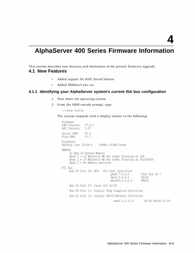
4.1.1 Identifying your AlphaServer system’s current ISA bus configuration
1. Shut down the operating system.
2. From the SRM console prompt, type:
>>>show config
The system responds with a display similar to the following:
FirmwareSRM Console: V7.0-1ARC Console: 4.57
Serial ROM: V3.4Diag ROM: V1.7
ProcessorDECchip (tm) 21064-2 166Mhz 512KB Cache
MEMORY32 Meg of System MemoryBank 0 = 16 Mbytes(8 MB Per Simm) Starting at 0x0Bank 1 = 16 Mbytes(8 MB Per Simm) Starting at 0x1000000Bank 2 = No Memory Detected
PCI BusBus 00 Slot 06: NCR 810 Scsi Controller
pka0.7.0.6.0 SCSI Bus ID 7dka0.0.0.6.0 RZ26Ldka400.4.0.6.0 RRD43
Bus 00 Slot 07: Intel SIO 82378
Bus 00 Slot 11: Digital ZLXp Graphics Controller
Bus 00 Slot 12: Digital DE435 Network Controller
ewa0.0.0.12.0 08-00-2B-E2-1C-25
AlphaServer 400 Series Firmware Information 4–1

ISASlot Device Name Type Enabled BaseAddr IRQ DMA0 0 MOUSE Embedded Yes 60 12
1 KBD Embedded Yes 60 12 COM1 Embedded Yes 3f8 43 COM2 Embedded Yes 2f8 34 LPT1 Embedded Yes 3bc 75 FLOPPY Embedded Yes 3f0 6 2
20 PCXBJ SingleporT Yes 530 9 0
3. From the information displayed in the previous step you can see the I/O Baseaddress (BaseAddr) and IRQ of the ISA devices that are known to the SRMconsole. Note that the Turbo Plus default base address (300) and IRQ (5) areavailable.
4. To check if there are any Turbo Plus boards installed, but not known to theconsole, use the EWRK3_CONFIG utility by typing:
>>>ewrk3_config>>>
If any Turbo Plus boards are present on your AlphaServer system, thiscommand displays their I/O Base addresses, otherwise the prompt returnswith no message as shown above.
5. The ISACFG utility is used to determine if any ISA devices are using memory.Type the isacfg command using the slot number of an ISA device from theshow config command. (The slot number is a unique number used for deviceidentification and does not relate to a physical slot number.) For example:
>>>isacfg -slot 2
The system responds with a display similar to the following: Note that I/Obase address is equal to iobase0, IRQ is equal to irq0, and Memory address isequal to membase0.
==============================================================handle: PCBXJetyp: 1slot: 2 dev: 0enadev: 1totdev: 1iobase0: 530 membase0: 8000000000000000iobase1: 388 memlen0: 8000000000000000iobase2: 8000000000000000 membase1: 8000000000000000iobase3: 8000000000000000 memlen1: 8000000000000000iobase4: 8000000000000000 membase2: 8000000000000000iobase5: 8000000000000000 memlen2: 8000000000000000rombase: 8000000000000000romlen: 8000000000000000dmamode0/chan0: 0 irq0: 9dmamode1/chan1: 1 irq1: 80000000dmamode2/chan2: 80000000 irq2: 80000000dmamode3/chan3: 80000000 irq3: 80000000==============================================================
Note that in the above display for the device in slot 2, the membase0 is8000000000000000. This means memory is not being used by this device.None of the devices in slot 0 use memory, so there is no conflict if the TurboPlus factory default memory address (d0000h) is used.
6. If there are no conflicts proceed to section II. If there are conflicts, proceed tosection III.
4–2 AlphaServer 400 Series Firmware Information

4.1.2 Installing a Turbo Plus when there are no bus conflicts
1. If there are no conflicts with the Turbo Plus default settings and theinformation you gathered in the previous section, type the following SRMconsole command:
>>>add_de205
This command executes a script containing the following isacfg command:
>>>isacfg -mk -slot 1 -dev 0 -handle DE200-LE -irq0 5 -iobase0 300-membase0 e0000 -memlen0 10000 -etyp 1 -enadev 1
Notes
The above command script assumes that slot 1 is unused. If slot 1 isused on your system, enter the above command manually and choose anunused slot number. Refer to the ISA Configuration Utility section formore information.
2. At the SRM prompt, type:
>>>init
This saves the changes just made to the configuration database into non-volatile RAM.
3. Install the Turbo Plus board into the system. Refer to Chapter 1 of theDEC EtherWORKS 3 Turbo Ethernet Controller User Information forinstructions.
4. After the board is installed, from the SRM console prompt, type:
>>>ewrk3_configfound board addr=300
The system responds with the I/O base address of the Turbo Plus board.
5. Boot the operating system.
4.1.3 Installing a Turbo Plus board where there are conflictsYou are in this section because adding your Turbo Plus board would result inconflicts among devices on the ISA bus. These conflicts could be caused by deviceshaving the same I/O base address, IRQ, or memory address. One likely reason forconflict is that you are adding a second or third Turbo Plus board.
1. Using the I/O base address, IRQ, and memory address values that yougathered in the first section of this release note, and the list of availablevalues for the Turbo Plus board from Appendix A of the DEC EtherWORKS 3Turbo User Information, locate non-conflicting values. Note that IRQ11 is notavailable on AlphaStations.
Record the desired valueshere:
I/O Baseaddress
_ __ __ __ __ __
IRQ _ __ __ __ __ __
MemoryAddress
_ __ __ __ __ __
AlphaServer 400 Series Firmware Information 4–3

2. Enter the Turbo Plus data into the console database by typing:
Note
The isacfg command can be entered on multiple lines by typing abackslash at the end of the line. The up arrow can be used to recallprevious commands.
>>>isacfg -slot 15 -irq0 10 -iobase0 320 -membase0 f0000 \_> -mk -handle DE200-LE -etyp 1 -enadev 1 -memlen0 10000
Where for this example:
• The -slot number can be any unused slot number (15 in this example).
• The -irq0 value is an available IRQ (10).
• The -iobase0 value is an available I/O Base address (320h).
• The -membase0 value is an available Memory Address (f0000h).
Always enter the other parameters as shown, where:
• -mk specifies that this entry is being added to the database.
• -handle binds the name DE200-LE to the driver. The Turbo Plus board(DE205) uses the handle DE200-LE.
• -etyp specifies the type of option (1 = singleport device).
• -enadev specifies that the entry is being enabled (1).
• -memlen0 specifies the length of the memory region.
If you need to modify an existing entry, use the -mod option. For example, ifthe Turbo Plus IRQ was entered as 10, but should have been 15, type:
>>>isacfg -slot 15 -irq0 15 -mod
Slot 15 identifies the entry to be modified with the new value of irq0.
3. At the SRM prompt, type:
>>>init
4. If the I/O Base address (default, 300) of the Turbo Plus board is in conflictwith another ISA device, use a hardstrap override to temporarily change theboard’s address. Table 1-1 and Figure 1-6 in the DEC EtherWORKS 3 UserInformation describe how to do the override.
5. Install the Turbo Plus board into the system. Refer to Chapter 1 of theDEC EtherWORKS 3 Turbo Ethernet Controller User Information forinstructions.
6. Use the EWRK3_CONFIG utility to modify the Turbo Plus board’s values:
>>>ewrk3_config -curaddr 200 -ioaddr 320 -irq 10 -memaddr f0000
Where:
• -curaddr is the temporary hardstrap override I/O Base address (W1 andW2 both in).
4–4 AlphaServer 400 Series Firmware Information

• -ioaddr is the I/O Base address (320) that will be used when the hardstrapoverride is removed and was the I/O address entered as -iobase0 in step 2of this section.
• -irq is the value of the IRQ (10) and was the same IRQ entered as -irq0 instep 2 of this section.
• -memaddr is the value of the Base memory address (f0000) and was thesame address entered as -membase0 in step 2 of this section.
The system responds with the message:
Unit must be power cycled for these changes to take affect
7. Power off the system.
8. Remove the new Turbo Plus board and disable the hardstrap override byremoving W1 and W2.
9. Re-insert the new Turbo Plus board, close the cover, and power on the system.
10. At the SRM prompt, type:
>>>ewrk3_configfound board addr=300found board addr=320
The system indicates that two Turbo Plus boards were found.
If you see an error message such as:
*** Error (ena0), network station address ROM has a bad checksum,
compare the I/O Base address reported by the ewrk3_config command withthe I/O address displayed by the show config command. If the ewrk3_configcommand reported the address you expected, return to Section III, Step 2 andmodify the I/O base address (iobase0) with the isacfg command.
If the ewrk3_config command reported an address you did not expect, returnto Section III, Step 6 and modify the I/O base address with the ewrk3_configcommand.
4.1.4 Help ScreensHelp screens are available for ISACFG and EWRK3_CONFIG. At the SRMconsole prompt, type:
>>>help isacfg
or
>>>help ewrk3_config
4.1.5 EWRK3_CONFIG Command InformationEWRK3_CONFIG is a utility that sets up the DE205 on board EEPROM.
Invoking "ewrk3_config" with no parameters searches the entire address space forDE205 modules and displays the addresses of all modules found.
The parameters for ewrk3_config command are:
none Find all DE205 boards and display their I/O Base address
-curaddr The current hex I/O base address of the module being changed
AlphaServer 400 Series Firmware Information 4–5

-ioaddr The hex I/O base address to change the current module
-irq The decimal IRQ value (valid values are 5, 10 or 15)
-fbus Fast bus enable
-ena16 16 bit bus enable
-memaddr Base memory address the board should respond to
-bufsize Buffer size of the memory address (2K, 32K or 64K)
-swflag Software flag field
-netmgt Net management field
-default Set the board back to the default settings
4–6 AlphaServer 400 Series Firmware Information

4.1.6 ISA Configuration UtilityISA devices are not capable of being probed for configuration information bythe DIGITAL UNIX or OpenVMS operating systems. Therefore, you must enterISA option information manually using the ISA configuration utility (ISACFG).You should run this utility before installing a new ISA option module on DigitalAlphaServer systems running either the DIGITAL UNIX or OpenVMS operatingsystems.
Command Format
The syntax of the ISACFG command is:
isacfg [-slot <slot#>] [-dev <device#>][-all|-rm|-mk|-mod] [-<field> <value>] . . .
Command Option Description
-all Shows the entire configuration table. Overrides all othercommands.
-dev <dev#> Optional; defaults to 0 if not entered. On a multifunction ormultiport adapter, this specifies the device on the adapter.
-dmachan{0-3} <#> Allows you to specify up to four DMA channels for the device.
-dmamode{0-3} <#> Allows you to specify the DMA type for -dmachan{0-3}. DMAmodes are:
1 - Block2 - Demand4 - Single8 - Cascade
-enadev <#> Allows you to specify whether an entry is enabled ordisabled. Disabled devices are not used in resource allocationcalculations. The possible values are:
0 - No (disabled)1 - Yes (enabled)
-etyp <#> Defines an entry type for this entry. The # sign can be:
0 - Causes the entry to be deleted1 - Single option2 - Embedded multiport device3 - Multiport option device
-handle <string> Binds a name to the driver (up to 15 characters).
-init Initializes the configuration table to the default settings.
-iobase{0-5} <#> Specifies up to six I/O base registers (in hexadecimal) for aparticular device entry.
-irq{0-3} <#> Allows you to assign up to four IRQ (interrupt request)channels to the device (use decimal IRQ levels).
-membase{0-2} <#> Specifies up to three R/W ISA memory regions.
-memlen{0-2} <#> Specifies the length corresponding to membase{0-2}.
-mk Adds an entry into the table.
-mod Modifies an entry in the table.
-rm Deletes an entry from the table.
AlphaServer 400 Series Firmware Information 4–7
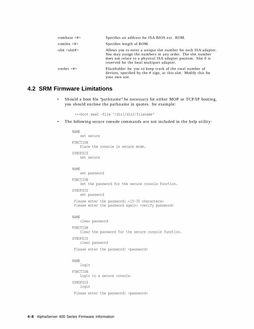
-rombase <#> Specifies an address for ISA BIOS ext. ROM.
-romlen <#> Specifies length of ROM.
-slot <slot#> Allows you to enter a unique slot number for each ISA adapter.You may assign the numbers in any order. The slot numberdoes not relate to a physical ISA adapter position. Slot 0 isreserved for the local multiport adapter.
-totdev <#> Placeholder for you to keep track of the total number ofdevices, specified by the # sign, at this slot. Modify this foryour own use.
4.2 SRM Firmware Limitations
• Should a boot file ‘‘pathname’’ be necessary for either MOP or TCP/IP booting,you should enclose the pathname in quotes. for example:
>>>boot ewa0 -file "/dir1/dir2/filename"
• The following secure console commands are not included in the help utility:
NAMEset secure
FUNCTIONPlace the console in secure mode.
SYNOPSISset secure
NAMEset password
FUNCTIONSet the password for the secure console function.
SYNOPSISset password
Please enter the password: <15-30 characters>Please enter the password again: <verify password>
NAMEclear password
FUNCTIONClear the password for the secure console function.
SYNOPSISclear password
Please enter the password: <password>
NAMElogin
FUNCTIONLogin to a secure console.
SYNOPSISlogin
Please enter the password: <password>
4–8 AlphaServer 400 Series Firmware Information

• For this release you can NOT update the AlphaServer 400 SRM firmwarevia the ARC 4.41 "Install new firmware" utility. The AlphaServer 400 SRMfirmware can only be updated from the SRM console (Section 1.2 in thisdocument).
AlphaServer 400 Series Firmware Information 4–9