Digital Vortex Mixer 20190926 Vor… · Digital Vortex Mixer 88882009 & 88882010 In the United...
10
Digital Vortex Mixer 88882009 & 88882010 In the United States: For customer service, call 1-800-766-7000 To fax an order, use 1-800-926-1166 To order online: thermofisher.com Find out more at thermofisher.com In Canada: For customer service, call 1-800-234-7437 To fax an order, use 1-800-463-2996 To order online: thermofisher.ca For Research Use Only. Not for use in diagnostic procedures. ©2019 Thermo Fisher Scientific Inc. All rights reserved. All trademarks are the property of Thermo Fisher Scientific and its subsidiaries unless otherwise specified. Operating Manual Revision A . 09 26 2019
Transcript of Digital Vortex Mixer 20190926 Vor… · Digital Vortex Mixer 88882009 & 88882010 In the United...

Digital Vortex Mixer88882009 & 88882010
In the United States:
For customer service, call 1-800-766-7000
To fax an order, use 1-800-926-1166To order online: thermofisher.com
Find out more at thermofisher.com
In Canada:
For customer service, call 1-800-234-7437
To fax an order, use 1-800-463-2996To order online: thermofisher.ca
For Research Use Only. Not for use in diagnostic procedures. © 2019 Thermo Fisher Scientific Inc. All rights
reserved. All trademarks are the property of Thermo Fisher Scientific and its subsidiaries unless otherwise specified.
Operating ManualRevision A . 09 26 2019

Section 1 Important Information
Disposing of Product
Section 2 Introduction
Feature
Packing List
Connections
Structure Diagram
Section 3 Overview
Specifications
Environmental Conditions
Section 4 Operation
Control Panel
Settings
Installation of Accessories
Section 5 Safety Tips
Section 6 Cleaning and Maintenance
Section 7 Troubleshooting
Section 8 Optional Accessories
Section 9 Warranty
Contents
1
2
3
3
4
4
4
5
5
5
6
6
7
9
11
12
13
14
16

Section 1 Important Information
Ignoring the following warnings could cause serious injuries or even fatal accidents.
Check the voltage, phase and capacity of power supply on the ID plate before installation. Connect properly.
Power supply must be properly grounded. Abnormal grounded connection causes serious damage. Grounded connection must not be on the water pipe and gas pipe.
Use provided power cord. Power cord: Wall outlet with grounded terminal power cord 250V 10A.
Do not install the product in a place that gas could leak. Do not use in a place that has industrial oil smoke or metallic dust. It causes fire or electric shock. Do not use the machine near to places where explosion could happen due to organic evaporating gases.
Explosive materials: acid, esther, nitro compound.
Inflammable materials: salt peroxides, inorganic peroxide, salt acids.
Check equipment for permissible environmental conditions when using inside of Temperature and Humidity Chamber or Incubator. It can be the cause of fire or trouble by stirrer electricity, electronic, and damage of motor.
Mixer's permissible environmental condition. Temperature 5°C to 40°C, Maximum relative humidity 85%.
Unplug if there is a strange sound, smell and/or smoke from the product. Stop
operating and request the service.
Keep out of the direct sunlight. It may influence product life and proper operation.
Do not use the machine at places where moisture is high and flooding can happen.
Do not assemble, repair, modify on your own. The product may not work well and electric shock is possible with changes in the efficiency of the product. Also this will void the warranty.
Indicates a hazardous situation which, if not avoided, may result in minor or moderate injury.
Do not put heavy things on the power cord. Do not put the machine on the cord. It may take off the wire coating and cause electric shock or fire.
Do not touch it with wet hands and place the main plug correctly. It could cause the electric shock or injuries.
Installing power outlet near instrument may be convenient
Do not install the Vortex Mixer near machinery generating high frequency noise. Avoid installation close to high frequency- welding machine, sewing machine, or mass SCR controller.
Do not inject any liquid and inflammable things inside of product.
Do not pour water or put liquid on the top of the product when cleaning. Disconnect the main power immediately and request the service if water may be in the product.
Do not let the product take any strong shock or vibration. It could cause abnormal operation or trouble. It may deteriorate the ability of the product operation and not obtain correct results.
Do not sprinkle insecticide or flammable spray on the product. Use smooth cloths. Cleaning with solvent can cause fire and deformity.
Power off while product cleaning. It may cause electric shock or fire.
Do not drop or allow the machine to fall. It will cause wrong operation and malfunction.
Disposing of Product
Dispose the unit with separating plastic mold, and motor.
1 | Section 1 Important Information Digital Vortex Mixer 2
Section 2 Introduction
Welcome to use Thermo Scientific
Vortex Mixers. Vortex mixers are used in
biomedical engineering, physical and
chemical analysis, environmental
monitoring, food, hygiene, petrochemical,
metallurgy and other fields, for cell
culture, sample tissue, chemical
reagents, bacteria liquid and other
substances mixed. It is suitable for test
tubes, centrifugal tubes, color tubes,
enzyme plates, deep hole plates, PCR
plates and other containers.
2.1 FeatureIt can be easily switched between touch
and continuous modes and the
corresponding light is on when working
normally.
◆It has speed adjustment display
function.
◆It has timing and LED time display
function for up to 99 minutes, which
can be freely switched minutes or
seconds.
◆It has a high sensitivity touch switch.
◆It uses keys and a simple control panel
and provides precise speed control.
◆The combined buttons can quickly set
the speed to 200rpm, 1500rpm,
3000rpm.
◆A variety of accessories can be
selected to maximize the needs of
customers.
◆It uses brushless DC motor, with
accurate speed control, stability, safe
and reliable features.
◆It has a power recovery function.
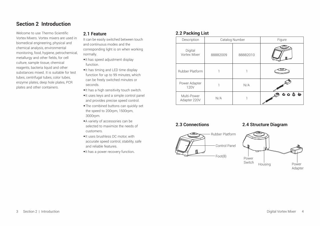
3 | IntroductionSection 2
2.3 Connections 2.4 Structure Diagram
Rubber Platform
Control Panel
Foot(8)PowerSwitch Power
AdapterHousing
Digital Vortex Mixer 4
Catalog Number
88882009
1
N/A 1
1
88882010
1
N/A
FigureDescription
2.2 Packing List
DigitalVortex Mixer
Rubber Platform
Power Adapter120V
Multi-PowerAdapter 220V

Section 3 Overview
3.1 Specifications
Speed Range......................................................200 to 3000rpmSpeed Accuracy.......................................................................±5%Orbit Diameter....................................................................¢4mmOperating Mode............................................Touch /Continuous
Maximum Load……………………………………............0.5kg @ 800rpm
Timing Range…………..……...................................0, 1sec.~99min.
Overall Dimensions........................................205×151×131mm
Platform Diameter...........................................................¢76mm
Net Weight.............................................................................6.5Kg
Requirement....................................AC100-240V, 50/60Hz, 6W
Certification..............................RoHS, WEEE, cCSAus, CE Mark
IP Class.....................................................................................Ip32
Application Environmental Conditions: indoor use
Temperature....................................................................5 to 40℃
Altitude...........................................................................≤2,000 m
Humidity...................................................................... 20% to 85%
Storage Environmental Conditions
Temperature....................................................................0 to 60℃
Altitude...........................................................................≤2,000 m
Humidity.......................................20% to 90%, non-condensing
3.2 Environmental Conditions
Rotation Speed
Load
Time
Size
Weight
Power Supply
Others
5 Section 3 | Overview Digital Vortex Mixer 6
Section 4 Operation
This chapter covers the control panel and its operation.
4.1 Control Panel
①. Time setting buttons: UP/DOWN
arrow buttons are used to increase/
decrease the set time of the
instrument.
②. Speed setting buttons: UP/DOWN
arrow buttons are used to increase/
decrease the set speed of the
instrument.
③. Time display window: The window
displays cumulative time (the set
time is “0”) or remaining time (the set
time is not “0").
④. Minute indicator: When in minute,
light up.
⑤. Second indicator: When in second,
light up.
⑥. Time unit select button: To switch
time unit between minute and second.
⑦. Mode button: To switch running mode
between "Touch" and "Continuous".
⑧. Touch Mode indicator: When in Touch
Mode, light up.
⑨. Continuous Mode indicator: When in
Continuous Mode, light up.
⑩. Run/Stop button: Run or stop the
instrument.
. Speed display window: The window
displays set speed (when the
instrument is in standby) or current
speed (when the instrument is
running).
① ②
③
④
⑤
⑥
Time
Time Speed
Continuous
TouchMode
Run
Stop
Minute
Second
rpm
⑩
⑦
⑧
⑨
11
11

target time (not “0”), put the vessel onto
the Rubber Platform or Flat Bottom
Vessel Platform and press, the
instrument runs at the set speed, and
the Time display windows show to
counts down. When stop pressing the
platform, the instrument stops and the
Time display windows flash. Within 5s,
put the vessels back and press onto the
platform, the timer continuously counts
down from last operation. After 5s, the
timer will be cleared and back to set
time. When the countdown time ends,
the instrument stops running, the Time
display windows flash three times, while
the buzzer calls three times, timer
display as 00. When stops vessel
pressing, the Time display windows
show the set time.
Power Recovery
Continuous Mode: If the power is cut off
suddenly while the instrument is in
operation, the instrument will resume the
parameters set before the power is cut
off, but the instrument will not continue
to run.
Touch Mode: The power is cut off when
the instrument is working. If the power is
on again, the instrument will resume the
parameters set before the power is off,
put the vessel onto the Rubber Platform
or Flat Bottom Vessel Platform and
press to run.
7 | Section 4 Operation
Timer Setting
1. Continuous mode
Timer: In standby, press “ ” or “ ”
button below the Time display window to
set the time to “0”, and then press the
“ ” button, the instrument runs at the
set speed, and the running time starts
counting. Press “ ” button again, the
instrument stops running.
Down counting: In standby, press “ ”
or “ ” button below the Time display
window to set a target time (not “0”), and
then press “ ” button, the instrument
runs at the set speed, and the running
time counts down. When the countdown
time ends, the instrument stops running,
the display windows flash three times,
while the buzzer calls three times, the
display windows show the set time and
speed.
2. Touch mode
Timer: In standby, set the time to “0”, put
the vessel onto the Rubber Platform or
Flat Bottom Vessel Platform and press
to run, the instrument runs at the set
speed, and the running time starts
counting. When stop pressing the
platform, the instrument stop running.
The Time display windows flash 5s.
Within 5s, put the vessels back and
press onto the platform, the timer
continuously counts from last operation.
After 5s, the timer will be cleared and
back to 0.
Down counting: In standby, set as a
4.2 SettingsPlease confirm the environmental
condition and the power voltage first,
and then, connect the mixer power cord
to the power outlet.
Switch On
Press the power switch to position “I”
and the display windows are shown as
below:
The corresponding indicator for the time
unit and running mode is on.
Mode Settings
In standby, press “ ” button to switch
“Touch” mode or “Continuous” mode. In
“Touch" mode, the instrument starts
running automatically when the vessel
presses on the Rubber Platform or Flat
Bottom vessel Platform, and
automatically stops when the vessel
leaves the platform. In “Continuous”
mode, press “ ” button, the instrument
with tray, platform or tube holder starts
running continuously, and press “ ”
button again, the instrument stops
running.
Speed setting
In standby, press “ ” or “ ” button
below the Speed display windows to set
the target speed, for example:
Run
Stop
Run
Stop
Run
Stop
Run
Stop
Run
Stop
Run
Stop
In this case, the set speed is 1600rpm.
Press “ ” button, the instrument will
slowly accelerate to 1600rpm, and the
Speed display windows show the actual
speed while the instrument remains in
rotation.
In running mode, press “ ” or “ ”
button to increase or decrease the speed
value. Release the button when the
speed shown on the Speed display
window reaches the set value. The
speed setting is finished after the
number shown on the Speed display
windows flashed three times.
Note: Press “ ” or “ ” button for a longer time to accelerate the setting.
Quick Speed Setting
The instrument can quickly set speed to
1500rpm, 3000rpm and 200rpm by
combination buttons.
In standby, press “ ” and “ ” button
at the same time under the Speed
display windows over 3s, the instrument
speed will be set to 1500rpm, over 6s,
the instrument speed will be set to
3000rpm, over 9s, the instrument speed
will be set to 200rpm.
Time Unit Setting (Continous mode)
In standby, press “ ” button to select
time unit “Second” or “Minute”, the
corresponding unit indicator light will be
on. Time range is 0 to 99s for “Second”,
and 0 to 99 minutes for “Minute”.
Time display window
Speed display window
0 0
1 6 0 0
0 2 0 0
Digital Vortex Mixer 8

Finish Operation
After use, please press power switch to
turn off the power. Unplug the
instrument and store it according to the
storage guide.
4.3 Installation of AccessoriesInstallation of Rubber Platform
1. Place the Rubber Platform on the
base tray .
2. Press evenly along the perimeter of
the Rubber Platform so that the
Rubber Platform is stuck on the base
tray.
Installation of Flat Bottom Vessel
Platform
1. Place the Flat Bottom Vessel Platform
on the top of the base tray and align
the inner bump of the Flat Bottom
Vessel Platform is to the groove on
the base tray.
2. Press evenly along the perimeter of
the Flat Bottom Vessel Platform so
that the Flat Bottom Vessel Platform
is stuck on the base tray.
Installation of Microplate Tray
Microplate Tray are suitable for
“continuous” mode and samples are
mixed with enzyme ELISA PLATE.
1. Parallel place the Microplate Tray on
the top of the base tray.
2. Gently press both sides of the
Microplate Tray to snap it onto the
base tray, and please make sure it
tighten.
Microplate Tray
Base Tray
Vessel Platform
Base Tray
Rubber Platform
Base Tray
Installation of Tube Holder
Tube Holder are suitable for
"Continuous" mode to mixing samples
by test tubes.
1. Parallel place the Tube Holder on the
top of the base tray.
2. Gently press both sides of the Tube
Holder to snap it onto the base tray,
and please make sure it tighten.
3. Install the corresponding EVA sponge
pad on the Tube Holder, after inserting
the test tube, it can start to run.
9 | Section 4 Operation Digital Vortex Mixer 10
EVA SpongePad
Tube Holder

Please read the manual carefully and
follow the following safety guidelines
before operating this instrument.
1. Please keep this manual for reference
for any time.
2. Professionals are required to operate
the instrument.
3. The instrument can only be used the
original power adapter.
4. When operating the instrument, the
operator must choose to wear
appropriate clothing to avoid toxic
and harmful solvents produced as
follows:
◆Harmful liquids splashed
◆The harmful solids ejected
◆Body, hair, clothing is rolled or
corroded
5. If the instrument becomes abnormal
or higher vibration in use, please
immediately reduce the speed
accordingly or immediately stop the
instrument.
6. Ensure that the accessories and
containers are installed correctly.
7. Please check the instrument and
accessories are in good condition
before each operation.
8. For a single test tube mixing, please
put test tube in the middle hole of the
rubber platform. For multi-test tube
mixing, please always place the test
tubes in the center and symmetrically.
9. Be careful of the risks that may arise.
◆Flammable substances
◆Fragile substances
10. Unplug the power before installing
the accessories.
11. Carefully handle the instrument to
avoid any collision or impact.
Section 6 Cleaning and MaintenanceSection 5 Safety Tips
Cleaning
In order to ensure the safe use of the
instrument, please follow the
manufacturer’s recommendations for
cleaning when cleaning the instrument.
● Unplug the power first when cleaning.
● Wipe the instrument with a damp, soft
cloth or non-corrosive cleaning agent
(ph 8).
● Direct spray instruments are
prohibited.
● Make sure that the instrument is
completely dry before operating it.
● Please wear gloves when cleaning.
Warning: Avoid dripping detergent or
water into the inside of the instrument
during cleaning.
Clean Spill
If accidental spillage of liquids caused by
mishandling or contained breakage
occurs on the surface of the instrument,
please shut down the instrument and
clean up the liquid immediately.If the
liquid has already spilled into the unit,
cut off the power supply first and
immediately clean up the liquid at the
surface of the instrument. Place the
instrument in a ventilated and dry
environment for 24 hours before reuse. If
the instrument is not functioning after
drying for 24 hours, please contact the
manufacturer.
Warning: Disassembling/Assembling
without a qualified professional's
guidance may cause malfunctioning of
the instrument.
Maintenance
Clean and make sure that there are no
harmful residues in the instrument
before delivery..
11 Section 5 | Safety Tips Digital Vortex Mixer 12

13 Section 7 | Troubleshooting
Section 7 Troubleshooting
Digital Vortex Mixer 14
Error Cause
Power disconnected
Power switch off
Solution
Connect the power
Switch on power
Please refer to the following table to
troubleshoot if any malfunction occurs.
If the problem still exists, contact your
local sales representative.
Not workingproperly
Loud noiseVibration large
Abnormal sound
The instrument is notstable
Place the instrument on ahorizontal, rugged platform
The sample in the testtube is imbalance
Contact with other objectsof the instrument’s case
Fill an equivalent amount ofsample in the test tube
Remove the objects contacted
Se
cti
on
8 O
pti
on
al
Ac
ce
ss
ori
es
De
sc
rip
tio
nC
at.
No
.F
igu
re
Ru
bb
er
Pla
tfo
rm
88
88
21
21
88
88
21
22
88
88
21
20
88
88
21
23
88
88
21
24
88
88
21
25
88
88
21
27
88
88
21
26
Mic
rop
late
Tra
y
Fla
t B
ott
om
Ve
ss
el P
latf
orm
10
mm
dia
x1
9 T
ub
e H
old
er
15
mm
dia
x 1
2 T
ub
e H
old
er
20
mm
dia
x 7
Tu
be
Ho
lde
r
26
mm
dia
x 4
Tu
be
Ho
lde
r
12
mm
dia
x 1
3 T
ub
e H
old
er
To
uc
hC
on
tin
uo
us
Sp
ee
d R
an
ge
Dim
en
sio
ns
20
0~
30
00
rpm
20
0~
30
00
rpm
20
0~
12
00
rpm
20
0~
20
00
rpm
20
0~
18
00
rpm
20
0~
10
00
rpm
20
0~
10
00
rpm
20
0~
90
0rp
m
13
6×
97
×1
1.5
mm
¢8
2×
16
.5m
m
¢8
0×
9m
m
¢1
00
×5
4m
m
¢1
00
×5
4m
m
¢1
00
×6
8m
m
¢1
00
×6
8m
m
¢1
00
×6
8m
m
√√ √ √ √ √ √√ √
√ - - - - - -

Note:
(1). When mixing by ELISA PLATE, the
capacity of the ELISA PLATE shall
not exceed 1/2 of the maximum
capacity. Otherwise, there may be
liquid splash.
(2). The Recommended speed values in
the table are for reference only.
Change the speed value according
to the actual operation of the
instrument.
Warning:
When replacing accessories, the
instrument must be in standby mode or
turn off the power.
15 Section 8 | Optional Accessories Digital Vortex Mixer 16
Section 9 Warranty
THERMO FISHER SCIENTIFIC
STANDARD PRODUCT WARRANTY
The Warranty Period starts two weeks
from the date your equipment is shipped
from our facility. This allows for shipping
time so the warranty will go into effect at
approximately the same time your
equipment is delivered. The warranty
protection extends to any subsequent
owner during the first year warranty
period.
During the first two (2) years, component
parts proven to be non-conforming in
materials or workmanship will be
repaired or replaced at Thermo's
expense, labor included. Installation and
calibration are not covered by this
warranty agreement. The Technical
Services Department must be contacted
for warranty determination and direction
prior to performance of any repairs.
Expendable items, glass, filters and
gaskets are excluded from this warranty.
Replacement or repair of components
parts or equipment under this warranty
shall not extend the warranty to either
the equipment or to the component part
beyond the original warranty period. The
Technical Services Department must
give prior approval for return of any
components or equipment. At Thermo's
option, all non-conforming parts must
be returned to Thermo Fisher Scientific
postage paid and replacement parts are
shipped FOB destination.
THIS WARRANTY IS EXCLUSIVE AND IN
LIEU OF ALL OTHER WARRANTIES,
WHETHER WRITTEN, ORAL OR IMPLIED.
NO WARRANTIES OF
MERCHANTABILITY OR FITNESS FOR A
PARTICULAR PURPOSE SHALL APPLY.
Thermo shall not be liable for any
indirect or consequential damages
including, without limitation, damages
relating to lost profits or loss of
products.
Your local Thermo Sales Office is ready
to help with comprehensive site
preparation information before your
equipment arrives. Printed instruction
manuals carefully detail equipment
installation, operation and preventive
maintenance.
If equipment service is required, please
call your Technical Services Department
at 1-866-984-3766, option number 2.
We're ready to answer your questions on
equipment warranty, operation,
maintenance, service and special
application. Outside the USA, please
contact local Thermo Technical Services
Department or local distributor for
warranty information.