Digital Video Broadcasting (DVB); Digital Satellite News ... · PDF fileDigital Video...
29
ETSI EN 301 222 V1.1.1 (1999-07) European Standard (Telecommunications series) Digital Video Broadcasting (DVB); Co-ordination channels associated with Digital Satellite News Gathering (DSNG) EBU UER European Broadcasting Union Union Européenne de Radio-Télévision
-
Upload
vuongthien -
Category
Documents
-
view
221 -
download
0
Transcript of Digital Video Broadcasting (DVB); Digital Satellite News ... · PDF fileDigital Video...
ETSI EN 301 222 V1.1.1 (1999-07)European Standard (Telecommunications series)
Digital Video Broadcasting (DVB);Co-ordination channels associated withDigital Satellite News Gathering (DSNG)
EBUUER
European Broadcasting Union Union Européenne de Radio-Télévision
ETSI
ETSI EN 301 222 V1.1.1 (1999-07)2
ReferenceDEN/JTC-DVB-82 (bbc00ico.PDF)
KeywordsDVB, digital, video, broadcasting, SNG, TV
ETSI
Postal addressF-06921 Sophia Antipolis Cedex - FRANCE
Office address650 Route des Lucioles - Sophia Antipolis
Valbonne - FRANCETel.: +33 4 92 94 42 00 Fax: +33 4 93 65 47 16
Siret N° 348 623 562 00017 - NAF 742 CAssociation à but non lucratif enregistrée à laSous-Préfecture de Grasse (06) N° 7803/88
Individual copies of this ETSI deliverablecan be downloaded from
http://www.etsi.orgIf you find errors in the present document, send your
comment to: [email protected]
Copyright Notification
No part may be reproduced except as authorized by written permission.The copyright and the foregoing restriction extend to reproduction in all media.
© European Telecommunications Standards Institute 1999.© European Broadcasting Union 1999.
All rights reserved.
ETSI
ETSI EN 301 222 V1.1.1 (1999-07)3
Contents
Intellectual Property Rights ............................................................................................................................... 4
Foreword ............................................................................................................................................................ 4
1 Scope........................................................................................................................................................ 5
2 References ............................................................................................................................................... 8
3 Symbols and abbreviations ...................................................................................................................... 83.1 Symbols ............................................................................................................................................................. 83.2 Abbreviations..................................................................................................................................................... 9
4 System definition................................................................................................................................... 10
5 Source coding and interfaces................................................................................................................. 115.1 Voice coding.................................................................................................................................................... 115.2 Data coding (Optional) .................................................................................................................................... 115.3 Signalling......................................................................................................................................................... 12
6 Multiplexing and interfaces................................................................................................................... 12
7 Transmission system and interfaces ...................................................................................................... 137.1 Randomization for energy dispersal................................................................................................................. 137.2 Inner coding (convolutional)............................................................................................................................ 147.3 Spread Spectrum.............................................................................................................................................. 157.4 Bit mapping, baseband shaping and modulation.............................................................................................. 177.4.1 Bit mapping to QPSK constellation ........................................................................................................... 177.4.2 Baseband shaping and quadrature modulation ........................................................................................... 18
8 Error performance requirements............................................................................................................ 18
Annex A (normative): Signal spectrum at the modulator output ................................................... 19
Annex B (normative): Transmission setups...................................................................................... 21
Annex C (normative): Implementation of "optional" features....................................................... 22
Annex D (informative): Examples of possible use of the System....................................................... 23
Bibliography .................................................................................................................................................... 28
History.............................................................................................................................................................. 29
ETSI
ETSI EN 301 222 V1.1.1 (1999-07)4
Intellectual Property RightsIPRs essential or potentially essential to the present document may have been declared to ETSI. The informationpertaining to these essential IPRs, if any, is publicly available for ETSI members and non-members, and can be foundin SR 000 314: "Intellectual Property Rights (IPRs); Essential, or potentially Essential, IPRs notified to ETSI in respectof ETSI standards", which is available free of charge from the ETSI Secretariat. Latest updates are available on theETSI Web server (http://www.etsi.org/ipr).
Pursuant to the ETSI IPR Policy, no investigation, including IPR searches, has been carried out by ETSI. No guaranteecan be given as to the existence of other IPRs not referenced in SR 000 314 (or the updates on the ETSI Web server)which are, or may be, or may become, essential to the present document.
ForewordThis European Standard (Telecommunications series) has been produced by the Joint Technical Committee (JTC)Broadcast of the European Broadcasting Union (EBU), Comité Européen de Normalisation ELECtrotechnique(CENELEC) and the European Telecommunications Standards Institute (ETSI).
NOTE: The EBU/ETSI JTC Broadcast was established in 1990 to co-ordinate the drafting of standards in thespecific field of broadcasting and related fields. Since 1995 the JTC Broadcast became a tripartite bodyby including in the Memorandum of Understanding also CENELEC, which is responsible for thestandardization of radio and television receivers. The EBU is a professional association of broadcastingorganizations whose work includes the co-ordination of its members' activities in the technical, legal,programme-making and programme-exchange domains. The EBU has active members in about 60countries in the European broadcasting area; its headquarters is in Geneva.
European Broadcasting UnionCH-1218 GRAND SACONNEX (Geneva)SwitzerlandTel: +41 22 717 21 11Fax: +41 22 717 24 81
Digital Video Broadcasting (DVB) Project
Founded in September 1993, the DVB Project is a market-led consortium of public and private sector organizations inthe television industry. Its aim is to establish the framework for the introduction of MPEG-2 based digital televisionservices. Now comprising over 200 organizations from more than 25 countries around the world, DVB fostersmarket-led systems, which meet the real needs, and economic circumstances, of the consumer electronics and thebroadcast industry.
National transposition dates
Date of adoption of this EN: 18 June 1999
Date of latest announcement of this EN (doa): 30 September 1999
Date of latest publication of new National Standardor endorsement of this EN (dop/e): 31 March 2000
Date of withdrawal of any conflicting National Standard (dow): 31 March 2000
ETSI
ETSI EN 301 222 V1.1.1 (1999-07)5
1 ScopeAccording to ITU-R Recommendation SNG.770-1, Satellite News Gathering (SNG) is defined as "Temporary andoccasional transmission with short notice of television or sound for broadcasting purposes, using highly portable ortransportable up-link earth stations …". EN 301 210 [2] describes the frame structure, channel coding and modulationsystem for Digital Satellite News gathering (DSNG).
For SNG technical and/or programme co-ordination, and interruptible feed-back, ITU-R Recommendation SNG.771-1recommends "that SNG earth stations should be equipped to provide two-way satellite communication circuits whichmust be available prior to, during and after, the transmission of the vision and associated sound or sound programmesignal. These circuits will provide communications between the SNG operator, the satellite operator and thebroadcaster; that two or more duplex circuits should be provided, whenever possible within the same transponder asthe programme vision and associated sound or sound programme signal". The same Recommendation considers "thatthroughout the world, where news events take place, uniform technical and operational standards for communicationshould be established to ensure prompt activation of the SNG service". The availability of co-ordination(communication) circuits by satellite may be particularly useful in areas where access to the public switched or cellulartelephone networks is difficult or impossible. For these purposes, the same antennas of the DSNG stations may often beused, and the same frequency resources (or at least the same satellite transponder) as the main DSNG signal may beexploited. Other frequency resources may also be chosen according to the operational conditions and requirements.
To achieve a two-way (i.e. full-duplex) communication channel, two independent carriers have to be transmitted, onefrom the DSNG terminal, the other from a fixed station. Depending on the service requirements, various scenarios arepossible, some of which require reduced communication capacity, others are more demanding (in terms of the number ofrequired connections and up-link facilities). Figure 1 shows two examples of implementation of the co-ordinationchannels between the DSNG terminal, the broadcaster, the DSNG operator (when required) and the satellite operator:
Scenario A (two up-links for co-ordination carriers): the DSNG terminal and a central station (e.g. the broadcaster'sfixed station) up-link a single co-ordination carrier each, containing U multiplexed circuits. In this scenario, theterrestrial infrastructure (e.g. PSTN) is used to forward the co-ordination circuits from the central station to the DSNGoperator and the satellite operator and the co-ordination equipment at the DSNG terminal has to transmit and receive asingle co-ordination carrier.
Scenario B (four up-links for co-ordination carriers): the DSNG terminal up-links a single co-ordination carrier,containing three multiplexed channels (U=3), while the broadcaster, the DSNG operator and the satellite operatorup-link a total of three co-ordination carriers, each with a single circuit. In this scenario, the co-ordination equipment atthe DSNG terminal has to transmit a single co-ordination carrier, and to receive three carriers at the same time.

ETSI
ETSI EN 301 222 V1.1.1 (1999-07)6
BROADCASTER
SATELLITE OPERATORSATELLITE
DSNG TERMINALSCENARIO A
with two up-links
PSTN
DSNG OPERATOR
BROADCASTER
SATELLITE
DSNG TERMINAL
DSNG OPERATOR
SATELLITE OPERATOR
CO-ORDINATIONSIGNALS
U=1,2,4MULTIPLEXED
CHANNELS
SCENARIO Bwith four up-links
DSNGSIGNAL
DSNGSIGNAL
CO-ORDINATIONSIGNALS
Figure 1: Example environments for DSNG and co-ordination transmissions by satellite
The present document describes the source coding (for voice and data), multiplexing, channel coding and modulationsystem (denoted as the "System" for the purposes of the present document) for the optional co-ordination(communication) channels by satellite associated with DSNG services. The integration of this System in a DSNG stationshall be optional, since other communication systems (e.g. PSTN, cellular phones connected to terrestrial or satellitenetworks) may be used, according to the prevailing operational needs.
Maximum compatibility with existing ETSI and ITU standards is maintained. In particular voice coding is performedaccording ITU-T Recommendation G.729 [5] (see note), offering high voice quality at 8 kbit/s (i.e. better than ADPCMat 32 kbit/s).
Data transmission is performed in synchronous RS-422 format, at bit-rates of 8, 16, or 32 kbit/s. Optionally it may beperformed in asynchronous RS-232 [7] format at a maximum bit-rate of 9,6; 19,2 or 38,4 kbit/s.
The System defined in the present document provides up to four full-duplex co-ordination (voice) channels at 8 kbit/s bysatellite, or data capacity for other applications. A co-ordination channel may also convey FAXes. A fixed time-divisionmultiplex allows the transmission of one, two or four 8 kbit/s channels producing an output bit-stream at 8,16 kbit/s,2 × 8,16 kbit/s, 4 × 8,16 kbit/s, respectively. The multiplex provides a signalling byte which indicates the multiplexconfiguration to the receiver.
ETSI
ETSI EN 301 222 V1.1.1 (1999-07)7
The system provides randomization for energy dispersal and inner convolutional coding (rate 1/2 only) for errorcorrection, to achieve high ruggedness against noise and interference. Reed-Solomon coding and convolutionalinterleaving are not used in the System, as the target BER (10-3) after FEC decoding is adequate for voicecommunication using ITU-R Recommendation G.729 [5], and additionally since they would generally introduce a largeend-to-end delay which may cause problems on voice communications in DSNG applications.
Direct-Sequence Spread-Spectrum (DS-SS) processing is applied before Quaternary Phase Shift Keying (QPSK)modulation, generating a modulated signal whose bandwidth occupation is expanded and whose power spectral densitylevel is reduced accordingly. DS-SS technique permits the superposition of a number of co-ordination signals in thefrequency domain (Code Division Multiple Access, CDMA), using the same centre frequency. For example thescenarios in Figure 1 may be efficiently implemented by using this technique. For system simplicity, the spreadingprocesses are asynchronous at each terminal, therefore the number of channels which may be superimposed is limited bymutual interference. Compared to conventional modulations, DS-SS techniques offer significant performanceimprovements in the presence of interferences (e.g. from and to co-channel narrow-band signals) and also produce lessintermodulation noise density over a non linear transponder. DS-SS signals also require less frequency precision in thetransmission/reception equipment.
The co-ordination carriers may be transmitted at a power level significantly lower than that of the DSNG carrier, sincetheir bit-rate is typically some hundred times lower than the DSNG bit-rate, therefore they do not significantly modifythe transponder operating point.
Flexible, user-definable frequency assignments may be used for the co-ordination channels, allowing the selection on acase-by-case basis of the best frequency division multiplex (FDM) configuration in the satellite transponder. Forexample, the System is capable of operating, if required, within the same frequency slot as the main DSNG signal, whilekeeping the level of mutual interference between the main DSNG signal and the co-ordination carriers at an acceptablelevel (see Annex D for further details). To achieve this, the co-ordination channels may be superimposed onto the mainDSNG signal (e.g. same centre frequency), at the cost of some performance degradation due to mutual interference,which may be more or less critical depending on the modulation/coding scheme of the DSNG system and on the mutualsignal levels. As an alternative, the co-ordination channels using a low spreading factor (e.g. 0,5 MHz or 1 MHzbandwidth occupation) may be allocated within the "roll-off" region of the DSNG signal, in order to reduce the mutualinterference between co-ordination and DSNG signals. In other cases, a clear frequency slot may be allocated to co-ordination channels, on the same transponder as the DSNG signal, or even on another transponder/satellite, according tothe service requirements.
The transmission parameters, such as the frequency, the symbol-rate and the spreading sequences are to be manually set-up in the co-ordination terminals; user definable configurations may be defined to simplify the link set-up (seeAnnex B).
The present document:
- gives a general description of the System;
- specifies source coding, multiplexing, channel coding and modulation of the signal, in order to allowcompatibility between equipments developed by different manufacturers. This is achieved by describing in detailthe signal processing principles at the transmitting side, while the processing at the receive side is left open todifferent implementation solutions. However, it is necessary in the present document to refer to certain aspects ofreception;
- identifies the global performance requirements and features of the System, in order to meet the service qualitytargets.
NOTE: The adoption of Annex A of ITU-T Recommendation G.729 [5] is under evaluation. Comments areinvited during the ETSI Public Enquiry.

ETSI
ETSI EN 301 222 V1.1.1 (1999-07)8
2 ReferencesThe following documents contain provisions which, through reference in this text, constitute provisions of the presentdocument.
• References are either specific (identified by date of publication, edition number, version number, etc.) ornon-specific.
• For a specific reference, subsequent revisions do not apply.
• For a non-specific reference, the latest version applies.
• A non-specific reference to an ETS shall also be taken to refer to later versions published as an EN with the samenumber.
[1] EN 300 421 (V.1.1.): "Digital Video Broadcasting (DVB); Framing structure, channel coding andmodulation for 11/12 GHz satellite services".
[2] EN 301 210: "Digital Video Broadcasting (DVB); Framing structure, channel coding andmodulation for Digital Satellite News Gathering (SNG) and other contribution applications bysatellite".
[3] ITU-R Recommendation SNG 770-1: "Uniform operational procedures for Satellite NewsGathering (SNG)".
[4] ITU-R Recommendation SNG 771-1: "Auxiliary co-ordination satellite circuits for SNGterminals".
[5] ITU-T Recommendation G.729: "Coding of speech at 8 kbit/s using Algebraic-Coded-ExcitedLinear-Prediction (CS-ACELP)".
[6] ITU-T Recommendation V.11: "Electrical characteristics for balanced double-current interchangecircuits operating at data signalling rates up to 10 Mbit/s".
[7] TIA/EIA RS-232: "Interface between data terminal equipment and data-circuit terminatingequipment employing serial binary data interchange".
[8] 4 wire E&M, 2 wire E&M.
[9] ITU-T Recommendation G.711: "Pulse code modulation (PCM) of voice frequencies".
[10] ITU-T Recommendation G.712: "Transmission performance characteristics of pulse codemodulation channels".
3 Symbols and abbreviations
3.1 SymbolsFor the purposes of the present document, the following symbols apply:
A Interference power suppression of each co-ordination channel by the baseband filter of the DSNGreceiver
a Roll-off factorC/N Carrier-to-noise power ratiodfree Convolutional code free distance∆ Eb/N0 degradation at the target BEREb/N0 Ratio between the energy per useful bit and twice the
two sided noise power spectral densityfN Nyquist frequencyf0 Centre frequency of a modulated signalG1,G2 Convolutional code generators

ETSI
ETSI EN 301 222 V1.1.1 (1999-07)9
GLR,GLS ML-sequence generatorsGSS1, GSS2 Spreading sequences generatorsΓ Ratio of the spectrum density of the DSNG signal and of each co-ordination signal divided by the
spreading factor LH(f) Baseband square root Raised Cosine filtering in the modulatorη Modulation/coding spectral efficiency (bits per transmitted symbol)I, Q In-phase, Quadrature phase components of the modulated signalK Convolutional code constraint lengthL Spreading sequence length (Spreading Factor) (bit)M Number of co-ordination carriers transmitted in CDMA configurationR Useful bit-rate before multiplexerRs Symbol rate corresponding to the bilateral Nyquist bandwidth of the modulated signal before
spread-spectrumRs,chip Chip symbol rate corresponding to the bilateral Nyquist bandwidth of the modulated signal after
SSRu Useful bit-rate after multiplexer, before channel encoderTs Period of unspread symbolTs,chip Period of the spread symbol, equal to 1/ Rs,chipU Number of channels at the MUX input (U = 1, 2, 4)X,Y Di-bit stream after rate 1/2 convolutional coding
The sub-script "COOR" refers to the co-ordination signals.
The sub-script "DSNG" refers to the main DSNG signal.
3.2 AbbreviationsFor the purposes of the present document, the following abbreviations apply:
AWGN Additive White Gaussian NoiseBB BasebandBER Bit Error RatioBS Bandwidth of the frequency Slot allocated to a serviceBW Bandwidth (at -3 dB) of the transponderCCITT International Telegraph and Telephone Consultative CommitteeCDMA Code Division Multiple AccessDEMUX De-multiplexerDSNG Digital Satellite News GatheringDS-SS Direct-Sequence Spread-SpectrumDTH Direct To HomeEBU European Broadcasting UnionETS European Telecommunication StandardFDM Frequency Division MultiplexFEC Forward Error CorrectionFIFO First-in, First-out shift registerFSS Fixed Satellite ServiceHEX Hexadecimal notationIBO Input Back OffIF Intermediate FrequencyIMUX Satellite transponder Input Multiplexer - FilterIRD Integrated Receiver DecoderITU International Telecommunications UnionMPEG Moving Pictures Experts GroupMSB Most Significant BitMUX MultiplexOBO Output Back OffOCT Octal notationOMUX Satellite transponder Output Multiplexer – FilterPCM Pulse-Code Modulationppm parts per million

ETSI
ETSI EN 301 222 V1.1.1 (1999-07)10
PRBS Pseudo Random Binary SequencePSTN Public Switched Telephone NetworkQPSK Quaternary Phase Shift KeyingRF Radio FrequencySNG Satellite News GatheringSS Spread SpectrumTBD To Be DefinedTDM Time Division MultiplexTV TelevisionTWTA Travelling Wave Tube Amplifier8PSK Octonary Phase Shift Keying16QAM 16 points Quadrature Amplitude Modulation
4 System definitionThe integration of this System in a DSNG station shall be optional, since other communication systems (e.g. PSTN,portable phones connected to terrestrial or satellite networks) may be used, according to the operational needs.
The co-ordination channels for DSNG applications consist of bi-directional (full-duplex) connections, therefore atransmitting and a receiving unit is necessary both at the DSNG up-link terminal, and at the fixed station(s).
The System is defined as the functional block of equipment performing voice coding, data transport, servicemultiplexing, channel coding and modulation to achieve adaptation to the satellite channel characteristics. Withreference to Figure 2, the external interfaces of the System shall be interface A (baseband interface) and interface C(Intermediate frequency interface). In Figure 2, the functional blocks "power and frequency adaptation" and thecombiner with the DSNG signal are not specified. Implementation of these is left to equipment designers. (Annex Dgives user guidelines for the use of the co-ordination channels). Interface B is an internal synchronous interface but itcan be made externally available as an option.
In particular, the following processes shall be applied to the data stream (see Figure 2):
- Voice coding at 8 kbit/s according to ITU-T Recommendation G.729 [5].
- Data coding (Optional).
- Multiplexing and framing.
- Multiplex adaptation and signal randomization for energy dispersal.
- Rate 1/2 convolutional inner coding with constraint length 7, according to EN 300 421 [1].
- Direct-Sequence Spread-Spectrum (DS-SS) processing (with five possible spreading factors: L=31, 63, 127,255 and 511).
- Bit mapping into QPSK constellation, according to EN 300 421 [1].
- Square-root raised cosine baseband shaping (roll-off factor a=0,35), according to EN 300 421 [1].
- Quadrature modulation, according to EN 300 421 [1].

ETSI
ETSI EN 301 222 V1.1.1 (1999-07)11
Voice/DataCoder
1
2
...
MUXand
framing QPSKModulator
BasebandShaping
Interface A Interface B Interface C
Power &FrequencyAdaptation
DS-SSProcessing
Spreadingsequences
Rate 1/2Convolut.
Code DSNGsignal
(DSNGup-linkonly)
MUXAdaptation&EnergyDispersal
InnerCoder
ModulatorMUXSourceCoding
U
RRu
U=1,2,4Ru=U×R ×204/200
Voice/DataCoder
Voice/DataCoder
Voice/DataCoder
DSNG signalCombiner
R=8 kbit/s (or 16 kbit/s or 32 kbit/s, for logical channel 1 only and for U=1)
Figure 2: Functional block diagram of the System
5 Source coding and interfaces
5.1 Voice codingVoice coding shall follow ITU-T Recommendation G.729 [5] at 8 kbit/s. This coder is designed to operate with a digitalsignal obtained by first performing telephone bandwidth filtering (ITU-T Recommendation G.712 [10]) of the analogueinput signal, then sampling it at 8 kHz, followed by conversion to 16-bit linear PCM for the input to the encoder.Following ITU-T Recommendation G.729 [5] other input characteristics, such as those specified by ITU-TRecommendation G.711 [9] for 64 kbit/s PCM data, should be converted to 16-bit linear PCM before encoding. Thebitstream at the encoder output is defined by ITU-T Recommendation G.729 [5].
This coding algorithm is transparent also to FAX signals, encoded according to ITU-T Recommendation (TBD).
Interface A (input of voice coder) shall be: 4-wire E&M, 2-wire E&M, Group 3 FAX [8]. The output of the voice coderis according to interface B as defined in Clause 6.
NOTE: Echo cancellation may be implemented in the receiver to overcome the effects on voice signals of thesatellite transmission delay.
5.2 Data coding (Optional)Transparent synchronous data streams at bit-rates of 8 kbit/s (logical channel 1, 2, 3, 4), 16 or 32 kbit/s (logical channel1 only) may be directly input to interface B. When externally available interface B (input of MUX) shall be synchronousserial RS-422 (Clock and data). The clock shall be synchronous on the U MUX inputs (U=1,2,4). The clock frequencyshall be 8 kHz (or 16 kHz or 32 kHz for logical channel 1 only), with a precision of ± 10 ppm.
Data coding shall adapt serial asynchronous RS-232 [7] signals at different bit-rates at interface A, to the synchronousstream at interface B.
In the cases of bit-rates of 8, 16 or 32 kbit/s at interface B, interface A (input to data encoder) shall be asynchronousRS-232 [7] at bit-rates up to 9,6; 19,2 or 38,4 kbit/s, respectively. The input characters shall be composed by 1 start bit,8 data bits (1 byte), 1 parity bit (even parity), 1 stop bit.
ETSI
ETSI EN 301 222 V1.1.1 (1999-07)12
The data encoder shall remove the start, parity and stop bits of the RS-232 [7] characters. The synchronous stream atinterface B shall be composed of "sections" of 25 bytes, delimited (at the beginning and at the end) by inverted or non-inverted reference-bytes to form 27-byte packets. The sections can be classified into two types:
• "transport sections", delimited by R = 11110000 (binary notation) reference-bytes;
• "counter sections", delimited by R = 00001111 (binary notation) inverted reference-bytes.
The transport sections shall be filled by the useful bytes (after elimination of start, parity and stop bits), starting from thefirst transmitted byte following the reference-byte. In the case there are not sufficient input bytes to fill a 25-byte section,the section shall be completed by E padding bytes, corresponding to P = 01001101 (binary notation). A partially ortotally empty transport section shall be followed by the relevant "counter section". A transport section totally filled byuseful bytes shall be followed by another transport section, thus avoiding efficiency losses when the maximum capacityis required.
A counter section shall contain a repeated counter-byte E signalling the number of empty bytes of the precedingtransport section. E shall be coded in binary format (e.g. E = 0000 0011 means 3 empty bytes in the previous transportsection). To increase the reception reliability in the presence of transmission errors, the counter-byte E shall be repeated13 times in the section, interleaved with inverted padding bytes P = 10110010 (binary notation). The configurationsE = 0 (full transport section) and E > 25 (decimal notation) are not permitted.
A counter section shall have the structure:
R | E | P | E | P | E | P | E | P | E | P | E | P | E | P | E | P | E | P | E | P | E | P | E | P | E | R
NOTE 1: The data coding protocol allows reliable reconstruction of the RS-232 [7] characters (e.g., elimination of"padding bytes" and of "counter sections") in the receiver also in presence of burst errors after Viterbidecoding. In fact the "counter sections" are characterized by the presence of two inverted reference-bytesR and of 12 inverted padding-bytes P, the counter-byte E is repeated 13 times and the padding bytes P inthe transport section are known a priori by the receiver.
NOTE 2: Data coding according to this section reduces the bit-rate of an input data stream at 9,6 kbit/s to9,6 x (8/11) x (27/25) = 7,54 kbit/s, compatible to the minimum capacity at interface B(i.e., 8 kbit/s - 10 ppm = 7,99992 kbit/s), with an additional tolerance of about 6% on the RS-232 [7]clock. Similar tolerances apply to the bit-rates of 19,2 and 38,4 kbit/s.
5.3 SignallingFor connection to the PSTN, voice-band signalling may be carried out using multi-frequency (MF) devices.
6 Multiplexing and interfacesThe multiplex shall provide U synchronous input channels at 8 kbit/s (U = 1, 2, 4) or one input channel (logicalchannel 1) at 16 kbit/s or at 32 kbit/s. Multiplexing of the U input channels shall be carried out by taking one byte persignal, starting from logical channel 1 to logical channel U.
For easy synchronization acquisition in the receiver (de-multiplexer, and QPSK phase ambiguity removal), themultiplexed data stream shall be framed in packets of 200 payload bytes, the first of which being a byte from logicalchannel 1, the I-th from logical channel I.
A two-byte Sync Word (47B8HEX), plus one byte for signalling MUX configuration to the receiver and one spare byte(not defined, for future applications) shall be inserted at the beginning of each 200-byte packet, to obtain a 204-bytepacket.

ETSI
ETSI EN 301 222 V1.1.1 (1999-07)13
The MUX configuration signalling byte shall have the format b0 b1 b2 b3 b4 b5 b6 b7, where bits b2⋅(I-1) b2⋅I-1 (I = 1, 2,3, 4) refer to channel I, and shall have the following values and meaning:
b2⋅(I-1) b2⋅I-1 = 0 0 = channel I not used;
0 1 = voice transmission (interface A);
1 0 = Synchronous data transmission, RS-422 format at interface B;
1 1 = Asynchronous data transmission, RS-232 [7] format at interface A.
The MUX configuration shall be static during a transmission. No error protection is inserted on the signalling byte since,due to its static nature and the repetitive transmission on each packet, it may be correctly recovered in presence of errors(for example, by multiple acquisition and majority logic decoding).
The output bit-rate of the MUX shall be Ru = U x (204/200) x R, where:
R = 8 kbit/s, 16 kbit/s or 32 kbit/s (for logical channel 1 when U = 1).
R = 8 kbit/s (for logical channels 1, 2, when U = 2; for logical channels 1, 2, 3, 4 when U = 4). Interface B (input to theMUX) shall be an internal interface or optionally shall be made externally available using synchronous serial RS-422(clock and data) according to ITU-T Recommendation V.11 [6] using 25 pin D connectors. The clock shall besynchronous on the U inputs (U = 1,2,4). The clock frequency shall be 8 kHz; when U = 1 the additional rates 16 kHz or32 kHz may be used on logical channel 1. A clock precision of 10 ppm is required at interface B, since it determines themodulation symbol rate.
7 Transmission system and interfacesThe transmission system shall be delimited by the following interfaces given in Table 1:
Table 1: Transmission system interfaces
Equipment type Interface Interface type ConnectionTransmit Input Internal at Ru from MUX
Output(interface C)
70/140 MHz IF,L-band IF,RF
to IF or RF devices
Receive Input 70/140 MHz IF,L-band IF,RF
from IF or RF devices
NOTE: Ru = U x (204/200) x R kbit/s, where R = 8 kbit/s (in addition R = 16 kbit/s or 32 kbit/s for logicalchannel 1 only, when U = 1).
7.1 Randomization for energy dispersalIn order to comply with ITU Radio Regulations and to ensure adequate binary transitions, the data stream at the outputof the MUX unit shall be bit-by-bit randomized. The polynomial of the PRBS generator shall be (see the scheme ofFigure 3 according to EN 300 421 [1]):
1 + x14 + x15
The processing order at the transmitting side shall always start from the Most Significant Bit (MSB) of the incomingserial byte sequence, and the Sync Word shall be inserted so that the MSB (i.e. bit 0 of the 01000111 byte) is processedfirst. The randomizer shall be loaded with the initialization sequence "1001 0101 0000 000" sequence at the beginningof each 204 byte packet. The first bit at the output of the PRBS generator shall be applied to the first bit (MSB) of thefirst byte following the Sync Word. The Sync Word shall not be randomized. The randomization process shall be activealso when the modulator input bit-stream is non-existent.

ETSI
ETSI EN 301 222 V1.1.1 (1999-07)14
1 2 3 4 5 6 7 8 9 10 11 12 13 14 15
1 0 0 1 0 1 0 1 0 0 0 0 0 0 0
AND
Enable Clear / Randomized
EX-OR EX-OR
Randomized / De-randomizedData output
Initializationsequence
Data input
0 0 0 0 0 0 1 1....
Data input (MSB first): 1 0 1 1 1 0 0 0 x x x x x x x x ....PRBS sequence : 0 0 0 0 0 0 1 1 ....
Figure 3: Randomizer / de-randomizer schematic diagram
7.2 Inner coding (convolutional)The System shall use a rate 1/2 convolutional code, with constraint length K = 7 corresponding to 64 trellis states(Figure 4) and dfree = 10, according to EN 300 421 [1] and EN 301 210 [2] (only rate 1/2 shall be used). The codegenerator polynomials shall be:
G1 = 171 (OCT) X output, I -Branch;
G2 = 133 (OCT) Y output, Q-Branch.
1-bit
delay
VHULDO
ELW�VWUHDP
1-bit
delay
Y output (133 octal)
1-bit
delay
1-bit
delay
1-bit
delay
1-bit
delay
Modulo-2 adder
Modulo-2 adder
X output (171 octal)
LQSXW
Figure 4: Principle scheme of the rate 1/2 convolutional code

ETSI
ETSI EN 301 222 V1.1.1 (1999-07)15
7.3 Spread SpectrumDirect-Sequence Spread-Spectrum (DS-SS) coding shall be applied to the output data stream of the convolutionalencoder. According to Figure 5, DS-SS shall consist of multiplying (digital EX-OR) each symbol of duration TS by adefined binary sequence of length L (spreading factor). The duration of the symbol of the spreading sequence, i.e. the"chip", shall be TS,chip, where TS,chip = TS / L (Ts being the symbol duration of the unspread sequence). Therefore thedata rate and also the RF bandwidth are increased by the factor L. Independent spreading sequences shall be applied tothe I-Branch and to the Q-Branch (dual BPSK mode), in order to minimize possible I-Q cross-talk effects.
Figure 5 shows the basic principle of Direct-Sequence Spread-Spectrum coding.
TS,chip
t
L . TS,chip = TS
TS,chip
t
X
XBinar y
Input (NRZ) from convolutional
Spreadin g Sequences
I-Branch
Q-Branch
To Baseband Filter
coder
Figure 5: Basic principle of Direct-Sequence Spread-Spectrum coding
The System shall implement five spreading factors, L = 31, 63, 127, 255 and 511 in order to offer flexibility in spectrumoccupation. The relevant bandwidth occupations (at -3 dB after baseband filtering), corresponding also to the chipsymbol rates, is RS,chip = L RS. Table 2 gives the bandwidth occupation versus the number of channels U and thespreading factor L.
Table 2: Bandwidth occupation [MHz] at –3 dB
Data rates atinterface B
L = 31 L = 63 L = 127 L = 255 L = 511
U=1 8 kbit/s (note) 0,25296 0,51408 1,03632 2,08080 4,16976U=2 16 kbit/s 0,50592 1,02816 2,07264 4,16160 8,33952U=4 32 kbit/s 1,01184 2,05632 4,14528 8,32320 Not allowedNOTE: When bit-rates of 16 kbit/s and 32 kbit/s are used at logical channel 1 (for U=1), the bandwidth figures
relevant to U=2 and U=4 apply, respectively.
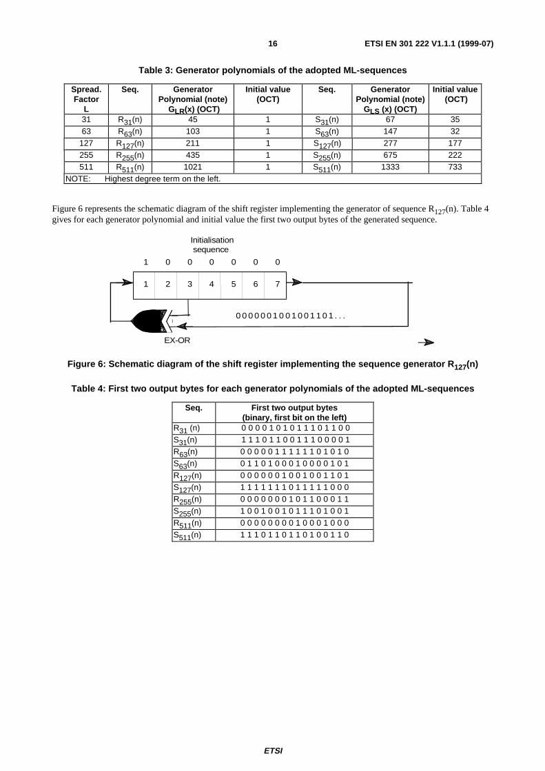
The spreading sequences are based on ML-sequences (ML = Maximum Length) and Gold-sequences. For each of thespreading lengths L, two ML-sequences RL(n) and SL(n), produced by the generator polynomials GLR(x) and GLS(x),shall be used, according to Table 3.
ETSI
ETSI EN 301 222 V1.1.1 (1999-07)16
Table 3: Generator polynomials of the adopted ML-sequences
Spread.Factor
L
Seq. GeneratorPolynomial (note)
GLR(x) (OCT)
Initial value(OCT)
Seq. GeneratorPolynomial (note)
GLS (x) (OCT)
Initial value (OCT)
31 R31(n) 45 1 S31(n) 67 3563 R63(n) 103 1 S63(n) 147 32
127 R127(n) 211 1 S127(n) 277 177255 R255(n) 435 1 S255(n) 675 222511 R511(n) 1021 1 S511(n) 1333 733
NOTE: Highest degree term on the left.
Figure 6 represents the schematic diagram of the shift register implementing the generator of sequence R127(n). Table 4gives for each generator polynomial and initial value the first two output bytes of the generated sequence.
1 2 3 4 5 6 7
1 0 0 0 0 0 0
EX-OR
Initialisation sequence
0 0 0 0 0 0 1 0 0 1 0 0 1 1 0 1 . . .
Figure 6: Schematic diagram of the shift register implementing the sequence generator R 127(n)
Table 4: First two output bytes for each generator polynomials of the adopted ML-sequences
Seq. First two output bytes(binary, first bit on the left)
R31 (n) 0 0 0 0 1 0 1 0 1 1 1 0 1 1 0 0S31(n) 1 1 1 0 1 1 0 0 1 1 1 0 0 0 0 1R63(n) 0 0 0 0 0 1 1 1 1 1 1 0 1 0 1 0S63(n) 0 1 1 0 1 0 0 0 1 0 0 0 0 1 0 1R127(n) 0 0 0 0 0 0 1 0 0 1 0 0 1 1 0 1S127(n) 1 1 1 1 1 1 1 0 1 1 1 1 1 0 0 0R255(n) 0 0 0 0 0 0 0 1 0 1 1 0 0 0 1 1S255(n) 1 0 0 1 0 0 1 0 1 1 1 0 1 0 0 1R511(n) 0 0 0 0 0 0 0 0 1 0 0 0 1 0 0 0S511(n) 1 1 1 0 1 1 0 1 1 0 1 0 0 1 1 0
ETSI
ETSI EN 301 222 V1.1.1 (1999-07)17
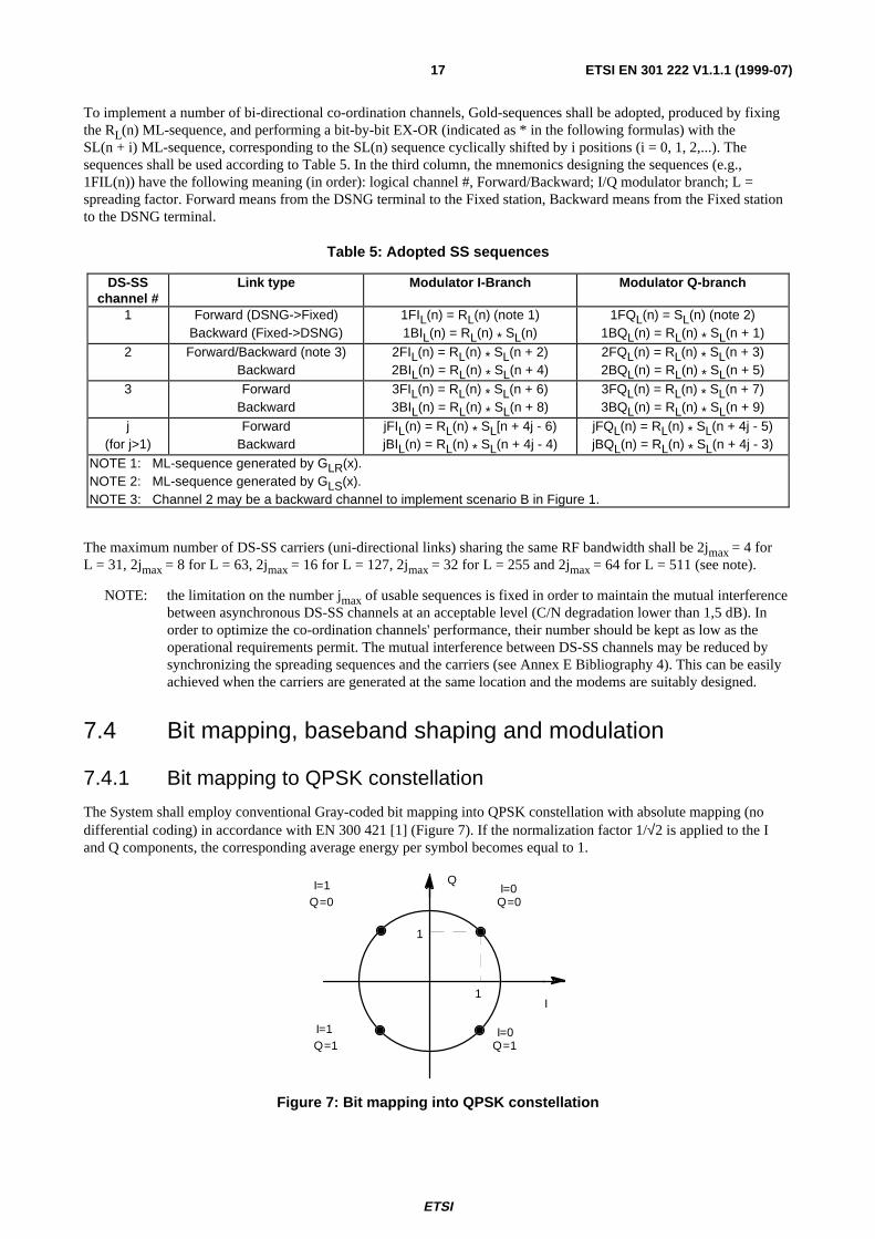
To implement a number of bi-directional co-ordination channels, Gold-sequences shall be adopted, produced by fixingthe RL(n) ML-sequence, and performing a bit-by-bit EX-OR (indicated as * in the following formulas) with theSL(n + i) ML-sequence, corresponding to the SL(n) sequence cyclically shifted by i positions (i = 0, 1, 2,...). Thesequences shall be used according to Table 5. In the third column, the mnemonics designing the sequences (e.g.,1FIL(n)) have the following meaning (in order): logical channel #, Forward/Backward; I/Q modulator branch; L =spreading factor. Forward means from the DSNG terminal to the Fixed station, Backward means from the Fixed stationto the DSNG terminal.
Table 5: Adopted SS sequences
DS-SSchannel #
Link type Modulator I-Branch Modulator Q-branch
1 Forward (DSNG->Fixed)Backward (Fixed->DSNG)
1FIL(n) = RL(n) (note 1)1BIL(n) = RL(n) * SL(n)
1FQL(n) = SL(n) (note 2)1BQL(n) = RL(n) * SL(n + 1)
2 Forward/Backward (note 3)Backward
2FIL(n) = RL(n) * SL(n + 2)2BIL(n) = RL(n) * SL(n + 4)
2FQL(n) = RL(n) * SL(n + 3)2BQL(n) = RL(n) * SL(n + 5)
3 ForwardBackward
3FIL(n) = RL(n) * SL(n + 6)3BIL(n) = RL(n) * SL(n + 8)
3FQL(n) = RL(n) * SL(n + 7)3BQL(n) = RL(n) * SL(n + 9)
j(for j>1)
ForwardBackward
jFIL(n) = RL(n) * SL[n + 4j - 6)jBIL(n) = RL(n) * SL(n + 4j - 4)
jFQL(n) = RL(n) * SL(n + 4j - 5)jBQL(n) = RL(n) * SL(n + 4j - 3)
NOTE 1: ML-sequence generated by GLR(x).NOTE 2: ML-sequence generated by GLS(x).NOTE 3: Channel 2 may be a backward channel to implement scenario B in Figure 1.
The maximum number of DS-SS carriers (uni-directional links) sharing the same RF bandwidth shall be 2jmax = 4 forL = 31, 2jmax = 8 for L = 63, 2jmax = 16 for L = 127, 2jmax = 32 for L = 255 and 2jmax = 64 for L = 511 (see note).
NOTE: the limitation on the number jmax of usable sequences is fixed in order to maintain the mutual interferencebetween asynchronous DS-SS channels at an acceptable level (C/N degradation lower than 1,5 dB). Inorder to optimize the co-ordination channels' performance, their number should be kept as low as theoperational requirements permit. The mutual interference between DS-SS channels may be reduced bysynchronizing the spreading sequences and the carriers (see Annex E Bibliography 4). This can be easilyachieved when the carriers are generated at the same location and the modems are suitably designed.
7.4 Bit mapping, baseband shaping and modulation
7.4.1 Bit mapping to QPSK constellation
The System shall employ conventional Gray-coded bit mapping into QPSK constellation with absolute mapping (nodifferential coding) in accordance with EN 300 421 [1] (Figure 7). If the normalization factor 1/√2 is applied to the Iand Q components, the corresponding average energy per symbol becomes equal to 1.
Q=0
Q
I
Q=1Q=1
1
1
I=0
I=0
Q=0I=1
I=1
Figure 7: Bit mapping into QPSK constellation
ETSI
ETSI EN 301 222 V1.1.1 (1999-07)18
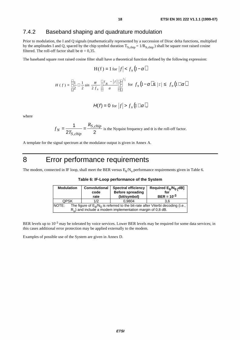
7.4.2 Baseband shaping and quadrature modulation
Prior to modulation, the I and Q signals (mathematically represented by a succession of Dirac delta functions, multipliedby the amplitudes I and Q, spaced by the chip symbol duration TS,chip = 1/RS,chip ) shall be square root raised cosinefiltered. The roll-off factor shall be α = 0,35.
The baseband square root raised cosine filter shall have a theoretical function defined by the following expression:
H f( ) = 1 for ( )α−< 1Nff
2
1
22
1
2
1)(
+=
−
α
π fN
f
NfsinfH for ( )α−1Nf ≤ f ≤ ( )α+1Nf
H f( ) = 0 for ( )α+> 1Nff ,
where
fT
RN
S chip
S chip= =12 2,
, is the Nyquist frequency and α is the roll-off factor.
A template for the signal spectrum at the modulator output is given in Annex A.
8 Error performance requirementsThe modem, connected in IF loop, shall meet the BER versus Eb/No performance requirements given in Table 6.
Table 6: IF-Loop performance of the System
Modulation Convolutionalcoderate
Spectral efficiencyBefore spreading
(bit/symbol)
Required E b/N0 [dB]for
BER = 10-3
QPSK 1/2 0,9804 3,6NOTE: The figure of Eb/N0 is referred to the bit-rate after Viterbi decoding (i.e.,
Ru) and include a modem implementation margin of 0,8 dB.
BER levels up to 10-3 may be tolerated by voice services. Lower BER levels may be required for some data services; inthis cases additional error protection may be applied externally to the modem.
Examples of possible use of the System are given in Annex D.
ETSI
ETSI EN 301 222 V1.1.1 (1999-07)19
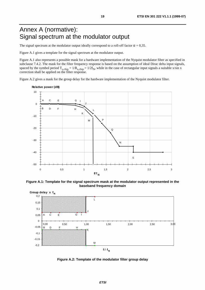
Annex A (normative):Signal spectrum at the modulator outputThe signal spectrum at the modulator output ideally correspond to a roll-off factor α = 0,35.
Figure A.1 gives a template for the signal spectrum at the modulator output.
Figure A.1 also represents a possible mask for a hardware implementation of the Nyquist modulator filter as specified insubclause 7.4.2. The mask for the filter frequency response is based on the assumption of ideal Dirac delta input signals,spaced by the symbol period Ts,chip = 1/Rs,chip = 1/2fN, while in the case of rectangular input signals a suitable x/sin xcorrection shall be applied on the filter response.
Figure A.2 gives a mask for the group delay for the hardware implementation of the Nyquist modulator filter.
Relative power (dB)
-50
-40
-30
-20
-10
0
10
0 0,5 1 1,5 2 2,5 3
A
B
C
D
E
F
G
H
J
KL
M
N
P
Q
S
I
f/f N
Figure A.1: Template for the signal spectrum mask at the modulator output represented in thebaseband frequency domain
f / f-0,2
-0,15
-0,1
-0,05
0
0,05
0,1
0,15
0,2
0,00 0,50 1,00 1,50 2,00 2,50 3,00
N
Group delay x f N
A
B
C
D
E
F
G
H
IJ
K
L
M
Figure A.2: Template of the modulator filter group delay

ETSI
ETSI EN 301 222 V1.1.1 (1999-07)20
Table A.1: Definition of points given in Figures A.1 and A.2
Point FrequencyFor α=0,35
Relative power(dB)
Group delay
A 0,0 fN +0,25 +0,07 / fNB 0,0 fN -0,25 -0,07 / fNC 0,2 fN +0,25 +0,07 / fND 0,2 fN -0,40 -0,07 / fNE 0,4 fN +0,25 +0,07 / fNF 0,4 fN -0,40 -0,07 / fNG 0,8 fN +0,15 +0,07 / fNH 0,8 fN -1,10 -0,07 / fNI 0,9 fN -0,50 +0,07 / fNJ 1,0 fN -2,00 +0,07 / fNK 1,0 fN -4,00 -0,07 / fNL 1,2 fN -8,00 -M 1,2 fN -11,00 -N 1,8 fN -35,00 -P 1,4 fN -16,00 -Q 1,6 fN -24,00 -S 2,12 fN -40,00 -

ETSI
ETSI EN 301 222 V1.1.1 (1999-07)21
Annex B (normative):Transmission setupsThe centre frequency and the power level of the co-ordination channels shall be selectable by the operator, in order toallow flexible access to the satellite frequency resources, including the superposition of the co-ordination channels to themain DSNG signal, or the exploitation of the roll-off part of the DSNG spectrum, or the use of frequency slotsspecifically assigned to co-ordination channels.
At least one user definable frequency and power set-up shall be provided by the co-ordination channel equipment, tofacilitate rapid link set-up in emergency situations. This frequency and power set-up shall be easily selectable in theequipment.
NOTE 1: For frequencies, bit-rates and symbol rates, typical accuracy is ± 10 ppm. For RF carriers higher accuracymay be required when low spreading factors are adopted.
NOTE 2: When the co-ordination signals are superimposed to the main DSNG signal, the power ratios of the DSNGand co-ordination channels have to be maintained at a suitable level, in order to guarantee the mutualperformance (see Annex D). Furthermore, the co-ordination carriers have to be maintained at balancedpower level (within about 2 dB at the receiver input), in order to guarantee a low level of mutualinterference.
ETSI
ETSI EN 301 222 V1.1.1 (1999-07)22
Annex C (normative):Implementation of "optional" featuresWithin the present document, a number of features has been defined as "optional". For example data coding is optional.Features explicitly indicated as "optional" within the present document need not be implemented in the equipment tocomply with the present document. Nevertheless, when an optional feature is implemented, it shall comply with thespecification as given in the present document.
ETSI
ETSI EN 301 222 V1.1.1 (1999-07)23
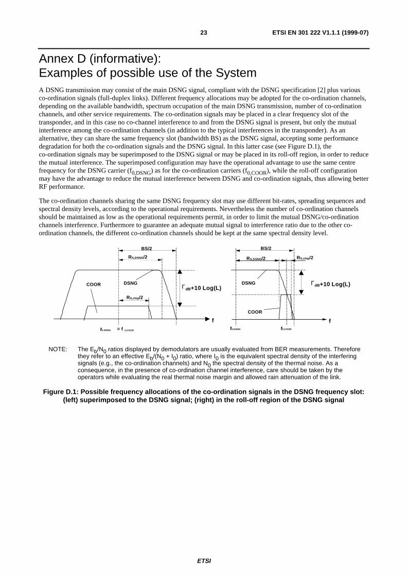
Annex D (informative):Examples of possible use of the SystemA DSNG transmission may consist of the main DSNG signal, compliant with the DSNG specification [2] plus variousco-ordination signals (full-duplex links). Different frequency allocations may be adopted for the co-ordination channels,depending on the available bandwidth, spectrum occupation of the main DSNG transmission, number of co-ordinationchannels, and other service requirements. The co-ordination signals may be placed in a clear frequency slot of thetransponder, and in this case no co-channel interference to and from the DSNG signal is present, but only the mutualinterference among the co-ordination channels (in addition to the typical interferences in the transponder). As analternative, they can share the same frequency slot (bandwidth BS) as the DSNG signal, accepting some performancedegradation for both the co-ordination signals and the DSNG signal. In this latter case (see Figure D.1), theco-ordination signals may be superimposed to the DSNG signal or may be placed in its roll-off region, in order to reducethe mutual interference. The superimposed configuration may have the operational advantage to use the same centrefrequency for the DSNG carrier (f0,DSNG) as for the co-ordination carriers (f0,COOR), while the roll-off configurationmay have the advantage to reduce the mutual interference between DSNG and co-ordination signals, thus allowing betterRF performance.
The co-ordination channels sharing the same DSNG frequency slot may use different bit-rates, spreading sequences andspectral density levels, according to the operational requirements. Nevertheless the number of co-ordination channelsshould be maintained as low as the operational requirements permit, in order to limit the mutual DSNG/co-ordinationchannels interference. Furthermore to guarantee an adequate mutual signal to interference ratio due to the other co-ordination channels, the different co-ordination channels should be kept at the same spectral density level.
f0,DSNG
f
COOR DSNG
BS/2
f0,DSNG f0,COOR
f
COOR
DSNG ΓdB+10 Log(L)ΓdB+10 Log(L)
= f 0,COOR
BS/2
RS,chip /2
RS,DSNG/2 RS,DSNG/2 RS,chip /2
NOTE: The Eb/N0 ratios displayed by demodulators are usually evaluated from BER measurements. Thereforethey refer to an effective Eb/(N0 + I0) ratio, where I0 is the equivalent spectral density of the interferingsignals (e.g., the co-ordination channels) and N0 the spectral density of the thermal noise. As aconsequence, in the presence of co-ordination channel interference, care should be taken by theoperators while evaluating the real thermal noise margin and allowed rain attenuation of the link.
Figure D.1: Possible frequency allocations of the co-ordination signals in the DSNG frequency slot:(left) superimposed to the DSNG signal; (right) in the roll-off region of the DSNG signal

ETSI
ETSI EN 301 222 V1.1.1 (1999-07)24
To estimate, to a first approximation, the impact of the co-ordination channels on the DSNG signal performance, thefollowing hypotheses have been adopted: (a) the transponder is operated in a quasi linear mode; (b) the interference ofthe DSNG signal on the co-ordination channels (and vice-versa) and the co-ordination channel interference due to theother co-ordination channels is equivalent to Gaussian noise of the same power. The latter approximation may beslightly pessimistic compared to digitally modulated signals, and applies under the assumption of non-synchronized andtherefore non-orthogonal spreading sequences. In this case the co-ordination channel signal to interference ratio due tothe other co-ordination channels can be approximated by the power ratio L/(M-1), where L indicates the spreadingfactor and M the number of co-ordination carriers in CDMA (ref. 4 Annex E). (When the co-ordination channels aresynchronized, the signal to interference power ratio can be approximated by the ratio L2/(M-1)).The Eb/N0 performancedegradation of the main DSNG signal ∆DSNG, due to the co-ordination channel interference, can be computed with theformulae:
∆DSNG = ρDSNG / (ρDSNG - 1)
ρDSNG = RDSNG A2/(M RCOOR (Eb/N0)COOR (Eb/N0)DSNG ρCOOR η2DSNG)
ρCOOR-1 = 1 - ∆COOR
-1 – ((L/(M - 1)) / (Eb/N0)COOR)-1
where M indicates the number of communication carriers (M = 2 corresponds to a single full-duplex connection),RDSNG and RCOOR the useful bit-rate for the main and co-ordination signals respectively, ηDSNG the modulation/codingspectral efficiency (bit/symbol) of the DSNG signal, ∆COOR the Eb/N0 performance degradation of the co-ordinationsignal, ρ is a parameter related to the ratio between C/N and C/I. A is the mutual interference power suppression of theDSNG and each co-ordination channel due to the baseband filtering in transmitters and receivers, assuming matchedfilters (see Figure A.1) (A = 1 for co-ordination signals superimposed to the DSNG signal). The factor A may becomputed by using the formula:
where HDSNG is the transfer function of the DSNG receive / transmit baseband filters and HCOOR is the transfer functionof the co-ordination receive/ transmit baseband filters (ideally corresponding to square root raised cosines).
Given the previously defined Eb/N0 performance degradation of the co-ordination signal ∆COOR, and therefore thefactor ρCOOR, the ratio Γ between the spectral densities of the DSNG signal and of each co-ordination signal divided bythe spreading factor L can be estimated as:
Γ = A/((Eb/N0)COOR ρCOOR ηCOOR) where: ηCOOR = 0,9804
Table D.1 reports a list of the symbols and their meanings.
Table D.1: List of the symbols
A Interference suppression in the baseband filters∆ Eb/N0 degradation at the target BEREb/N0 Ratio between the energy per useful bit and twice the two sided thermal noise power spectral densityΓ Ratio of the spectrum density of the DSNG signal and of each co-ordination signal divided by the spreading
factor Lη Modulation/coding spectral efficiency (bits per transmitted symbol)L Spreading sequence length (Spreading Factor) (bit)M Number of co-ordination carriers transmitted in CDMA configurationR Useful bit-rate before multiplexerNOTE: The sub-script COOR refers to the co-ordination signals.
The sub-script DSNG refers to the main DSNG signal.
∫∞
∞−
−−= df)]ff(f[H)f(HR
1A COOR,0DSNG,0
2COOR
2DSNG
COOR,S

ETSI
ETSI EN 301 222 V1.1.1 (1999-07)25
Assuming superimposed frequency sharing as in Figure D.1 (left), Figures D.2 and D.3 give examples of the mainDSNG signal Eb/N0 performance degradation ∆DSNG. The main DSNG signal has a symbol rate of 6,666 MBaud, thusoccupying a frequency slot of 9 MHz. A fixed degradation of the co-ordination channel performance of 4,33 dB (seenote) has been imposed, due to interferences from DSNG signal and from other co-ordination channels. The required(Eb/N0)COOR is 3,6 dB at target BER of 10-3 (see Table 6). The DSNG schemes considered are QPSK, 8PSK, 16QAM,assuming the IF-loop performance given in [2]. In Figures D.2 and D.3, the adopted Γ factor is also given, representingthe ratio between the DSNG and co-ordination channel spectral density divided by the spreading factor L. OtherΓ factors may be chosen, according to the performance requirements. Lower Γ figures improve the performance of theco-ordination channels, while larger Γ figures improve the DSNG performance.
NOTE: This corresponds to a fixed BER of about 10-5 after Viterbi decoder in the absence of thermal noise.
Example 1 (Figure D.2): 8 kbit/s per co-ordination carrier, different number of unidirectional channels M.
0.0
0.5
1.0
1.5
2.0
2.5
3.0
3.5
4.0
1/2 2/3 3/4 5/6 7/8 2/3 5/6 8/9 3/4 7/8
L=63 L=127 L=511
QPSK 8PSK 16QAM
M=6
M=4
M=2
∆ DSNG [dB] given ∆
COOR =4,33 dB
∆ COOR
= 4 , 3 3 d B
L M Γ [dB]
2 4 6
6 3
1 2 7
5 1 1
- 5 , 9
- 5 , 7
- 5 , 6
- 6 , 4
- 6 , 0
- 5 , 7
- 7 , 1
- 6 , 3
- 5 , 8
Figure D.2: 8 kbit/s co-ordination channels superimposed to DSNG.Example performance degradation of DSNG (R S = 6,666 MBaud) interfered with by M co-ordination
signals, with L = 63, L = 127 and L = 511. The degradation of the co-ordination channelshas been assumed to be ∆COOR = 4,33 dB
Table D.1 reports the meaning of the symbols.
Assuming a DSNG signal using QPSK FEC rate 2/3, from Figure D.2 (8 kbit/s channels) an estimated DSNGdegradation of 0,7 dB is obtained for M = 6 and L = 63. For higher DSNG spectrum efficiency modes (e.g. 8PSK and16QAM), the interference degradation progressively increases and may become unpractical.
Example 2 (Figure D.3): 32 kbit/s per co-ordination carrier, different number of unidirectional channels M.
For 32 kbit/s co-ordination channels and M = 2, a degradation on the DSNG signal (QPSK 1/2, 2/3 and 3/4) lowerthan 1 dB is achieved.

ETSI
ETSI EN 301 222 V1.1.1 (1999-07)26
L=63 L=127
∆ COOR
=4,33 dB
Γ [dB]
2 4 L M
0.0
0.5
1.0
1.5
2.0
2.5
3.0
3.5
4.0
1/2 2/3 3/4 5/6 7/8 2/3 5/6 8/9 3/4 7/8
QPSK 8PSK 16QAM
∆ DSNG [dB] given ∆
COOR =4,33 dB
M=4
M=2
127 -5,7 -6,0
63 -5,9 -6,4
Figure D.3: 32 kbit/s co-ordination channels superimposed to DSNG.Example performance degradation of DSNG (R S = 6,666 MBaud) interfered with by M co-ordination
signals, with L = 63 and L = 127. The degradation of the co-ordination channelshas been assumed to be ∆COOR = 4,33 dB
Table D.1 reports the meaning of the symbols.
As indicated in Figure D.1 (right), to reduce mutual interference, the co-ordinations channels may be placed in theroll-off region of the DSNG signal. In order to minimize the mutual interference, the co-ordination signals may use alow spreading factor (i.e. L = 31, L = 63 or L = 127, according to the co-ordination channel bit-rate) and may be placed,for example, in the upper part of the frequency slot allocated to DSNG. In this configuration the centre frequency f0,
COOR of the co-ordination signals may be computed by the following formula:
f0,COOR = f0,DSNG + BS / 2 – (1,35 / 2) RS,COOR
where:
f0,DSNG is the centre frequency of the DSNG signal and BS the bandwidth of the frequency slot, RS,COOR = RS,chip is theco-ordination channel symbol rate.
In the following, the achievable performance is given for two example configurations, based on the frequencyallocations of formula (2) and choosing Γ equal – 3 dB as a reasonable practical upper limit for the power density levelof the co-ordination channels.
Example 3 (Figure D.4): 8 kbit/s co-ordination channels
M unidirectional co-ordination channels are considered, each at 8 kbit/s, with a spreading factor of 63 and 127. Themain DSNG signal has a symbol rate of 6,666 MBaud, thus occupying a frequency slot of 9 MHz. The roll-off region(from the –3 dB point to the slot margin) is 1,167 MHz wide, while the co-ordination signal bandwidth is about0,5 MHz for spreading factor 63 and 1 MHz for spreading factor 127. Due to the roll-off filter effect, the mutualinterference suppression A is about 5,5 dB for L = 127 and 9,7 dB for L = 63. The resulting performance degradationsof the DSNG signal are reported in Figure D.3, assuming a Γ factor (ratio between the DSNG and each co-ordinationchannel spectral density divided by the spreading factor L) of -3 dB (the – sign indicates that the co-ordination channelsbefore SS have a spectral density higher than that of the DSNG signal). In the example, even in the case of M = 6 theDSNG degradation may be maintained below 0,5 dB for DSNG modulations up to 16QAM FEC rate 3/4.

ETSI
ETSI EN 301 222 V1.1.1 (1999-07)27
0.0 0.1
0.2 0.3 0.4 0.5 0.6 0.7 0.8
1/2 2/3 3/4 5/6 7/8 2/3 5/6 8/9 3/4 7/8
QPSK 8PSK 16QAM
∆ COOR
[dB]
2 4 6 L M
M=6
M=4
M=2
L=63 L=127
∆ DSNG [dB] given Γ =-3 dB
63 0,7 1,1 1,6
127 1,8 2,1 2,3
Figure D.4: 8 kbit/s co-ordination channels in the "Roll-off" region of DSNG.Example performance degradation of DSNG (RS = 6,666 MBaud) interfered with by M co-ordination
signals, with L = 63 and L = 127. The ratio between the DSNG and each co-ordination channelspectral density divided by the spreading factor L has been assumed to be Γ = -3 dB
Table D.1 reports the meaning of the symbols.
Example 4 (Figure D.5): 32 kbit/s co-ordination channels.
M unidirectional co-ordination channels are considered, each at 32 kbit/s, with a spreading factor of 31. The mainDSNG signal has a symbol rate of 6,666 MBaud, thus occupying a frequency slot of 9 MHz. The roll-off region (fromthe –3 dB point to the slot margin) is 1,167 MHz wide, while the co-ordination signal bandwidth is about 1 MHz. Due tothe roll-off filter effect, the mutual interference suppression A is about 5,5 dB. The resulting performance degradationsof the DSNG signal are reported in Figure D.5, assuming a Γ factor of - 3 dB (the – sign indicates that the co-ordinationchannels before SS have a spectral density higher than DSNG). In the example, in the case of M = 4 the DSNGdegradation may be maintained below 0,5 dB for DSNG modulations up to 8PSK FEC rate 2/3.
0.0
0.5
1.0
1.5
2.0
2.5
1/2 2/3 3/4 5/6 7/8 2/3 5/6 8/9 3/4 7/8
Q P S K 8 P S K 1 6 Q A M
M = 2 ∆
COOR = 2,2 d B
M = 4 ∆
COOR = 3,4 d B
∆ DSNG [dB] given Γ =-3 dB
Figure D.5: 32 kbit/s co-ordination channels in the "Roll-off" region of DSNG.Example performance degradation of DSNG (RS = 6,666 MBaud) interfered with by M co-ordinationsignals, with L = 31. The ratio between the DSNG and each co-ordination channel spectral density
divided by the spreading factor L has been assumed to be Γ −3 dB
Table D.1 reports the meaning of the symbols.
ETSI
ETSI EN 301 222 V1.1.1 (1999-07)28
BibliographyThe following material, though not specifically referenced in the body of the present document (or not publiclyavailable), gives supporting information.
U. Reimers, NAB'93, (EBU V4/MOD 249): "The European perspectives on Digital Television Broadcasting".
A. Morello, V. Mignone, "The New DVB Standard for Digital Satellite News Gathering", IBC'98 Conference,Amsterdam, 11-15 September, 1998.
J. K. Holmes, "Coherent Spread Spectrum Systems", Krieger Publishing Company, Malabar, Florida.
R. De Gaudenzi, C. Elia, R. Viola, "Bandlimited Quasi-Synchronous CDMA: A novel Satellite Access Technique forMobile and Personal Communications", IEEE Journal on Selected Areas in Comm. Vol 10, No. 2, February 1992,pp. 328-343.
TBR 30: "Satellite Earth Stations and Systems (SES); Satellite News Gathering (SNG) Transportable Earth Stations(TES) operating in the 11-12/13-14 GHz frequency bands".
ETS 300 673: "Radio Equipment and Systems (RES); ElectroMagnetic Compatibility (EMC) standard for 4/6 GHz and11/12/14 GHz Very Small Aperture Terminal (VSAT) equipment and 11/12/13/14 GHz Satellite News Gathering(SNG) Transportable Earth Station (TES) equipment".
ETSI
ETSI EN 301 222 V1.1.1 (1999-07)29
History
Document history
V1.1.1 February 1999 One-step Approval Procedure OAP 9924: 1999-02-12 to 1999-06-11
V1.1.1 July 1999 Publication
ISBN 2-7437-3222-9Dépôt légal : Juillet 1999
![Digital Video Broadcasting (DVB); Framing Structure ... · [1] ETSI EN 300 744: "Digital Video Broadcasting (DVB); Framing structure, channel coding and modulation for digital terrestrial](https://static.fdocuments.us/doc/165x107/5f2491fb1507063d664f2f07/digital-video-broadcasting-dvb-framing-structure-1-etsi-en-300-744-digital.jpg)