Digital Temperature Controllers (Simple Type) User's Manual
100
Digital Temperature Controllers (Simple Type) User’s Manual E5CC-800 E5EC-800 H211-E1-02 Preparations Introduction Index Appendices Part Names and Basic Procedures 1 2 3 A I
Transcript of Digital Temperature Controllers (Simple Type) User's Manual
Digital Temperature Controllers(Simple Type)User’s ManualE5CC-800E5EC-800
H211-E1-02
Preparations
Introduction
Index
Appendices
Part Names andBasic Procedures
1
2
3
A
I


1
Preface
Digital Temperature Controllers (Simple Type) User’s Manual (H211)
Preface
The E5CC and E5EC are Digital Controllers. The main functions and characteristics of these DigitalControllers are as follows:
• Any of the following types of input can be used: thermocouple, platinum resistance thermometer,infrared sensor, analog voltage, or analog current.
• Either standard or heating/cooling control can be performed. • Both auto-tuning and self-tuning are supported.• Event inputs can be used to switch set points (multi-SP function), switch between RUN and STOP
status, switch between automatic and manual operation, and perform other operations.• Heater burnout detection and heater short (HS) alarms functions are supported. (Applicable models
with heater burnout detection function.)• Communications are supported. (Applicable to models with communications.)• The structure is waterproof (IP66).• Conforms to UL, CSA, and IEC safety standards and EMC Directive.
Read this manual thoroughly and be sure you understand it before attempting to use the Digital Control-ler and use the Digital Controller correctly according to the information provided. Keep this manual in asafe place for easy reference.There are two types of E5CC/E5EC Digital Controllers: The E5CC/E5EC-@-0@@ Standard-type DigitalControllers and the Simple-type E5CC/E5EC-@-8@@ Digital Controllers. This manual describes how touse the E5CC/E5EC-@-8@@ Simple-type Digital Controllers. For detailed specifications of functions,refer to the E5CC/E5EC Digital Temperature Controllers User’s Manual (Cat. No. H174). In this manual,“E5CC/E5EC” or “E5CC-800/E5EC-800” is used to indicated the E5CC/E5EC-@-8@@ Simple-type Dig-ital Controllers. Refer to the following manual for further information on communications: E5CC/E5ECDigital Temperature Controllers Communications Manual (Cat. No. H175).
© OMRON, 2012All rights reserved. No part of this publication may be reproduced, stored in a retrieval system or transmitted, in any form, or by any means, mechanical, electronic, photocopying, recording, or otherwise, without the prior written permission of OMRON.No patent liability is assumed with respect to the use of the information contained herein. Moreover, because OMRON is constantly striving to improve its high-quality products, the information contained in this manual is subject to change without notice. Every precaution has been taken in the preparation of this manual. Nevertheless, OMRON assumes no responsibility for errors or omissions. Neither is any liability assumed for damages resulting from the use of the information contained in this publication.

Read and Understand this Manual
2 Digital Temperature Controllers (Simple Type) User’s Manual (H211)
Read and Understand this Manual
Please read and understand this manual before using the products. Please consult your OMRON representative if you have any questions or comments.
Warranty and Limitations of Liability
WARRANTY
OMRON's exclusive warranty is that the products are free from defects in materials and workmanship for a period of one year (or other period if specified) from date of sale by OMRON.
OMRON MAKES NO WARRANTY OR REPRESENTATION, EXPRESS OR IMPLIED, REGARDING NON-INFRINGEMENT, MERCHANTABILITY, OR FITNESS FOR PARTICULAR PURPOSE OF THE PRODUCTS. ANY BUYER OR USER ACKNOWLEDGES THAT THE BUYER OR USER ALONE HAS DETERMINED THAT THE PRODUCTS WILL SUITABLY MEET THE REQUIREMENTS OF THEIR INTENDED USE. OMRON DISCLAIMS ALL OTHER WARRANTIES, EXPRESS OR IMPLIED.
LIMITATIONS OF LIABILITY
OMRON SHALL NOT BE RESPONSIBLE FOR SPECIAL, INDIRECT, OR CONSEQUENTIAL DAMAGES, LOSS OF PROFITS OR COMMERCIAL LOSS IN ANY WAY CONNECTED WITH THE PRODUCTS, WHETHER SUCH CLAIM IS BASED ON CONTRACT, WARRANTY, NEGLIGENCE, OR STRICT LIABILITY.
In no event shall the responsibility of OMRON for any act exceed the individual price of the product on which liability is asserted.
IN NO EVENT SHALL OMRON BE RESPONSIBLE FOR WARRANTY, REPAIR, OR OTHER CLAIMS REGARDING THE PRODUCTS UNLESS OMRON'S ANALYSIS CONFIRMS THAT THE PRODUCTS WERE PROPERLY HANDLED, STORED, INSTALLED, AND MAINTAINED AND NOT SUBJECT TO CONTAMINATION, ABUSE, MISUSE, OR INAPPROPRIATE MODIFICATION OR REPAIR.

3
Read and Understand this Manual
Digital Temperature Controllers (Simple Type) User’s Manual (H211)
Application Considerations
SUITABILITY FOR USE
OMRON shall not be responsible for conformity with any standards, codes, or regulations that apply to the combination of products in the customer's application or use of the products.
At the customer's request, OMRON will provide applicable third party certification documents identifying ratings and limitations of use that apply to the products. This information by itself is not sufficient for a complete determination of the suitability of the products in combination with the end product, machine, system, or other application or use.
The following are some examples of applications for which particular attention must be given. This is not intended to be an exhaustive list of all possible uses of the products, nor is it intended to imply that the uses listed may be suitable for the products:
• Outdoor use, uses involving potential chemical contamination or electrical interference, or conditions or uses not described in this manual.
• Nuclear energy control systems, combustion systems, railroad systems, aviation systems, medical equipment, amusement machines, vehicles, safety equipment, and installations subject to separate industry or government regulations.
• Systems, machines, and equipment that could present a risk to life or property.
Please know and observe all prohibitions of use applicable to the products.
NEVER USE THE PRODUCTS FOR AN APPLICATION INVOLVING SERIOUS RISK TO LIFE OR PROPERTY WITHOUT ENSURING THAT THE SYSTEM AS A WHOLE HAS BEEN DESIGNED TO ADDRESS THE RISKS, AND THAT THE OMRON PRODUCTS ARE PROPERLY RATED AND INSTALLED FOR THE INTENDED USE WITHIN THE OVERALL EQUIPMENT OR SYSTEM.
PROGRAMMABLE PRODUCTS
OMRON shall not be responsible for the user's programming of a programmable product, or any consequence thereof.

Read and Understand this Manual
4 Digital Temperature Controllers (Simple Type) User’s Manual (H211)
Disclaimers
CHANGE IN SPECIFICATIONS
Product specifications and accessories may be changed at any time based on improvements and other reasons.
It is our practice to change model numbers when published ratings or features are changed, or when significant construction changes are made. However, some specifications of the products may be changed without any notice. When in doubt, special model numbers may be assigned to fix or establish key specifications for your application on your request. Please consult with your OMRON representative at any time to confirm actual specifications of purchased products.
DIMENSIONS AND WEIGHTS
Dimensions and weights are nominal and are not to be used for manufacturing purposes, even when tolerances are shown.
PERFORMANCE DATA
Performance data given in this manual is provided as a guide for the user in determining suitability and does not constitute a warranty. It may represent the result of OMRON's test conditions, and the users must correlate it to actual application requirements. Actual performance is subject to the OMRON Warranty and Limitations of Liability.
ERRORS AND OMISSIONS
The information in this manual has been carefully checked and is believed to be accurate; however, no responsibility is assumed for clerical, typographical, or proofreading errors, or omissions.

5
Safety Precautions
Digital Temperature Controllers (Simple Type) User’s Manual (H211)
Safety Precautions
Definition of Precautionary InformationThe following notation is used in this manual to provide precautions required to ensure safe usage ofthe product.The safety precautions that are provided are extremely important to safety. Always read and heed theinformation provided in all safety precautions. The following notation is used.
CAUTIONIndicates a potentially hazardous situation which, if not avoided,may result in minor or moderate injury or in property damage.
Symbols
Symbol Meaning
Caution
• General Caution Indicates non-specific general cautions, warnings, and dangers.
• Electrical Shock CautionIndicates possibility of electric shock under specific conditions.
Prohibition
• General ProhibitionIndicates non-specific general prohibitions.
Mandatory Caution
• General CautionIndicates non-specific general cautions, warnings, and dangers.

Safety Precautions
6 Digital Temperature Controllers (Simple Type) User’s Manual (H211)
Safety Precautions
*1 A SELV circuit is one separated from the power supply with double insulation or reinforced insulation, thatdoes not exceed 30 V r.m.s. and 42.4 V peak or 60 VDC.
*2 A class 2 power supply is one tested and certified by UL as having the current and voltage of thesecondary output restricted to specific levels.
CAUTION
Minor injury due to electric shock may occasionally occur.Do not touch the terminals while power is being supplied.
Electric shock, fire, or malfunction may occasionally occur.Do not allow metal objects, conductors, cuttings from installationwork, or moisture to enter the Digital Controller.
Minor injury from explosion may occasionally occur.Do not use the product where subject to flammable or explosive gas.
Minor electric shock, fire, or malfunction may occasionally occur.Never disassemble, modify, or repair the product or touch any of theinternal parts.
CAUTION - Risk of Fire and Electric Shock(a) This product is UL recognized as Open Type Process Control
Equipment. It must be mounted in an enclosure that does notallow fire to escape externally.
(b) More than one disconnect switch may be required tode-energize the equipment before servicing.
(c) Signal inputs are SELV, limited energy. *1
(d) Caution: To reduce the risk of fire or electric shock, do not
interconnect the outputs of different Class 2 circuits.*2
If the output relays are used past their life expectancy, contact fusing or burning may occasionally occur.Always consider the application conditions and use the output relayswithin their rated load and electrical life expectancy. The lifeexpectancy of output relays varies considerably with the output loadand switching conditions.

7
Safety Precautions
Digital Temperature Controllers (Simple Type) User’s Manual (H211)
CAUTION
Loose screws may occasionally result in fire. Tighten the terminal screws to the specified torque of 0.43 to 0.58N·m.
Set the parameters of the product so that they are suitable for thesystem being controlled. If they are not suitable, unexpectedoperation may occasionally result in property damage or accidents.
A malfunction in the Digital Controller may occasionally make controloperations impossible or prevent alarm outputs, resulting in propertydamage. To maintain safety in the event of malfunction of the DigitalController, take appropriate safety measures, such as installing amonitoring device on a separate line.
Precautions for Safe Use
8 Digital Temperature Controllers (Simple Type) User’s Manual (H211)
Precautions for Safe Use
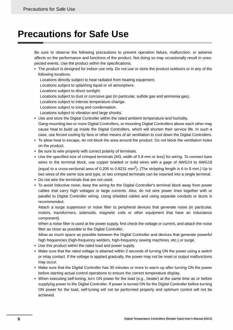
Be sure to observe the following precautions to prevent operation failure, malfunction, or adverseaffects on the performance and functions of the product. Not doing so may occasionally result in unex-pected events. Use the product within the specifications. • The product is designed for indoor use only. Do not use or store the product outdoors or in any of the
following locations.Locations directly subject to heat radiated from heating equipment.Locations subject to splashing liquid or oil atmosphere.Locations subject to direct sunlight.Locations subject to dust or corrosive gas (in particular, sulfide gas and ammonia gas).Locations subject to intense temperature change.Locations subject to icing and condensation.Locations subject to vibration and large shocks.
• Use and store the Digital Controller within the rated ambient temperature and humidity.Gang-mounting two or more Digital Controllers, or mounting Digital Controllers above each other maycause heat to build up inside the Digital Controllers, which will shorten their service life. In such acase, use forced cooling by fans or other means of air ventilation to cool down the Digital Controllers.
• To allow heat to escape, do not block the area around the product. Do not block the ventilation holeson the product.
• Be sure to wire properly with correct polarity of terminals.• Use the specified size of crimped terminals (M3, width of 5.8 mm or less) for wiring. To connect bare
wires to the terminal block, use copper braided or solid wires with a gage of AWG24 to AWG18
(equal to a cross-sectional area of 0.205 to 0.8231 mm2). (The stripping length is 6 to 8 mm.) Up totwo wires of the same size and type, or two crimped terminals can be inserted into a single terminal.
• Do not wire the terminals that are not used.• To avoid inductive noise, keep the wiring for the Digital Controller's terminal block away from power
cables that carry high voltages or large currents. Also, do not wire power lines together with orparallel to Digital Controller wiring. Using shielded cables and using separate conduits or ducts isrecommended.Attach a surge suppressor or noise filter to peripheral devices that generate noise (in particular,motors, transformers, solenoids, magnetic coils or other equipment that have an inductancecomponent).When a noise filter is used at the power supply, first check the voltage or current, and attach the noisefilter as close as possible to the Digital Controller.Allow as much space as possible between the Digital Controller and devices that generate powerfulhigh frequencies (high-frequency welders, high-frequency sewing machines, etc.) or surge.
• Use this product within the rated load and power supply.• Make sure that the rated voltage is attained within 2 seconds of turning ON the power using a switch
or relay contact. If the voltage is applied gradually, the power may not be reset or output malfunctionsmay occur.
• Make sure that the Digital Controller has 30 minutes or more to warm up after turning ON the powerbefore starting actual control operations to ensure the correct temperature display.
• When executing self-tuning, turn ON power for the load (e.g., heater) at the same time as or beforesupplying power to the Digital Controller. If power is turned ON for the Digital Controller before turningON power for the load, self-tuning will not be performed properly and optimum control will not beachieved.

9
Precautions for Safe Use
Digital Temperature Controllers (Simple Type) User’s Manual (H211)
• A switch or circuit breaker should be provided close to Digital Controller. The switch or circuit breakershould be within easy reach of the operator, and must be marked as a disconnecting means forDigital Controller.
• Wipe off any dirt from the Digital Controller with a soft dry cloth. Never use thinners, benzine, alcohol,or any cleaners that contain these or other organic solvents. Deformation or discoloration may occur.
• Design the system (e.g., control panel) considering the 2 seconds of delay in setting the DigitalController’s output after the power supply is turned ON.
• The output will turn OFF when you move to the Initial Setting Level. Take this into consideration whenperforming control.
• The number of non-volatile memory write operations is limited. Therefore, use RAM write mode whenfrequently overwriting data during communications or other operations.
• Use suitable tools when taking the Digital Controller apart for disposal. Sharp parts inside the DigitalController may cause injury.
• Do not exceed the communications distance that is given in the specifications. Use the specifiedcommunications cable.

Installation Precautions
10 Digital Temperature Controllers (Simple Type) User’s Manual (H211)
Installation Precautions
Service LifeUse the Digital Controller within the following temperature and humidity ranges:Temperature: −10 to 55°C (with no icing or condensation), Humidity: 25% to 85%If the Digital Controller is installed inside a control board, the ambient temperature must be kept tounder 55°C, including the temperature around the Controller. The service life of electronic devices like Digital Controllers is determined not only by the number oftimes the relay is switched but also by the service life of internal electronic components. Componentservice life is affected by the ambient temperature: the higher the temperature, the shorter theservice life and, the lower the temperature, the longer the service life. Therefore, the service life canbe extended by lowering the temperature of the Digital Controller. When two or more Digital Controllers are mounted horizontally close to each other or vertically nextto one another, the internal temperature will increase due to heat radiated by the Digital Controllersand the service life will decrease. In such a case, use forced cooling by fans or other means of airventilation to cool down the Digital Controllers. When providing forced cooling, however, be carefulnot to cool down the terminals sections alone to avoid measurement errors.
Ambient NoiseTo avoid inductive noise, keep the wiring for the Digital Controller's terminal block wiring away frompower cables carrying high voltages or large currents. Also, do not wire power lines together with orparallel to Digital Controller wiring. Using shielded cables and using separate conduits or ducts isrecommended.Attach a surge suppressor or noise filter to peripheral devices that generate noise (in particular,motors, transformers, solenoids, magnetic coils or other equipment that have an inductance compo-nent). When a noise filter is used at the power supply, first check the voltage or current, and attachthe noise filter as close as possible to the Digital Controller.Allow as much space as possible between the Digital Controller and devices that generate powerfulhigh frequencies (high-frequency welders, high-frequency sewing machines, etc.) or surge.
Ensuring Measurement AccuracyWhen extending or connecting the thermocouple lead wire, be sure to use compensating wires thatmatch the thermocouple types. When extending or connecting the lead wire of the platinum resistance thermometer, be sure to usewires that have low resistance and keep the resistance of the three lead wires the same. Mount the Digital Controller so that it is horizontally level. If the measurement accuracy is low, check to see if input shift has been set correctly.

11
Installation Precautions
Digital Temperature Controllers (Simple Type) User’s Manual (H211)
WaterproofingThe degree of protection is as shown below. Sections without any specification on their degree ofprotection or those with IP@0 are not waterproof.Front panel: IP66Rear case: IP20, Terminal section: IP00When waterproofing is required, insert the Waterproof Packing on the backside of the front panel.The degree of protection when the Waterproof Packing is used is IP66. To maintain an IP66 degreeof protection, the Waterproof Packing must be periodically replaced because it may deteriorate,shrink, or harden depending on the operating environment. The replacement period will vary withthe operating environment. Check the required period in the actual application. Use 3 years orsooner as a guideline. If the Waterproof Packing and Port Cover are not periodically replaced,waterproof performance may not be maintained. If a waterproof structure is not required, then theWaterproof Packing does not need to be installed.

Precautions for Operation
12 Digital Temperature Controllers (Simple Type) User’s Manual (H211)
Precautions for Operation
• It takes approximately two seconds for the outputs to turn ON from after the power supply is turnedON. Due consideration must be given to this time when incorporating Digital Controllers into a controlpanel or similar device.
• Make sure that the Digital Controller has 30 minutes or more to warm up after turning ON the powerbefore starting actual control operations to ensure the correct temperature display.
• When using self-tuning, turn ON power for the load (e.g., heater) at the same time as or beforesupplying power to the Digital Controller. If power is turned ON for the Digital Controller before turningON power for the load, self-tuning will not be performed properly and optimum control will not beachieved. When starting operation after the Digital Controller has warmed up, turn OFF the powerand then turn it ON again at the same time as turning ON power for the load. (Instead of turning theDigital Controller OFF and ON again, switching from STOP Mode to RUN Mode can also be used.)
• Avoid using the Digital Controller in places near a radio, television set, or wireless installing. TheDigital Controller may cause radio disturbance for these devices.
13
Preparations for Use
Digital Temperature Controllers (Simple Type) User’s Manual (H211)
Preparations for Use
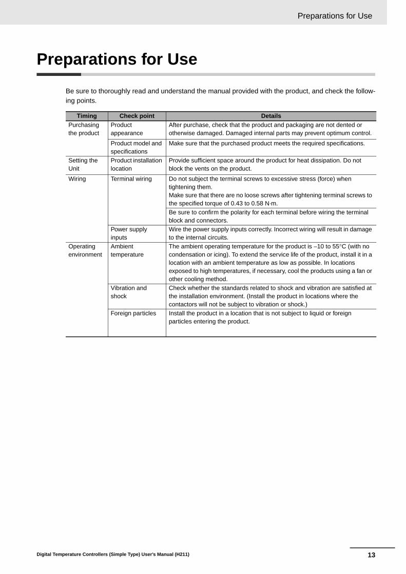
Be sure to thoroughly read and understand the manual provided with the product, and check the follow-ing points.
Timing Check point DetailsPurchasing the product
Product appearance
After purchase, check that the product and packaging are not dented or otherwise damaged. Damaged internal parts may prevent optimum control.
Product model and specifications
Make sure that the purchased product meets the required specifications.
Setting the Unit
Product installation location
Provide sufficient space around the product for heat dissipation. Do not block the vents on the product.
Wiring Terminal wiring Do not subject the terminal screws to excessive stress (force) when tightening them.Make sure that there are no loose screws after tightening terminal screws to the specified torque of 0.43 to 0.58 N·m.
Be sure to confirm the polarity for each terminal before wiring the terminal block and connectors.
Power supply inputs
Wire the power supply inputs correctly. Incorrect wiring will result in damage to the internal circuits.
Operating environment
Ambient temperature
The ambient operating temperature for the product is −10 to 55°C (with no condensation or icing). To extend the service life of the product, install it in a location with an ambient temperature as low as possible. In locations exposed to high temperatures, if necessary, cool the products using a fan or other cooling method.
Vibration and shock
Check whether the standards related to shock and vibration are satisfied at the installation environment. (Install the product in locations where the contactors will not be subject to vibration or shock.)
Foreign particles Install the product in a location that is not subject to liquid or foreign particles entering the product.
Revision History
14 Digital Temperature Controllers (Simple Type) User’s Manual (H211)
Revision History
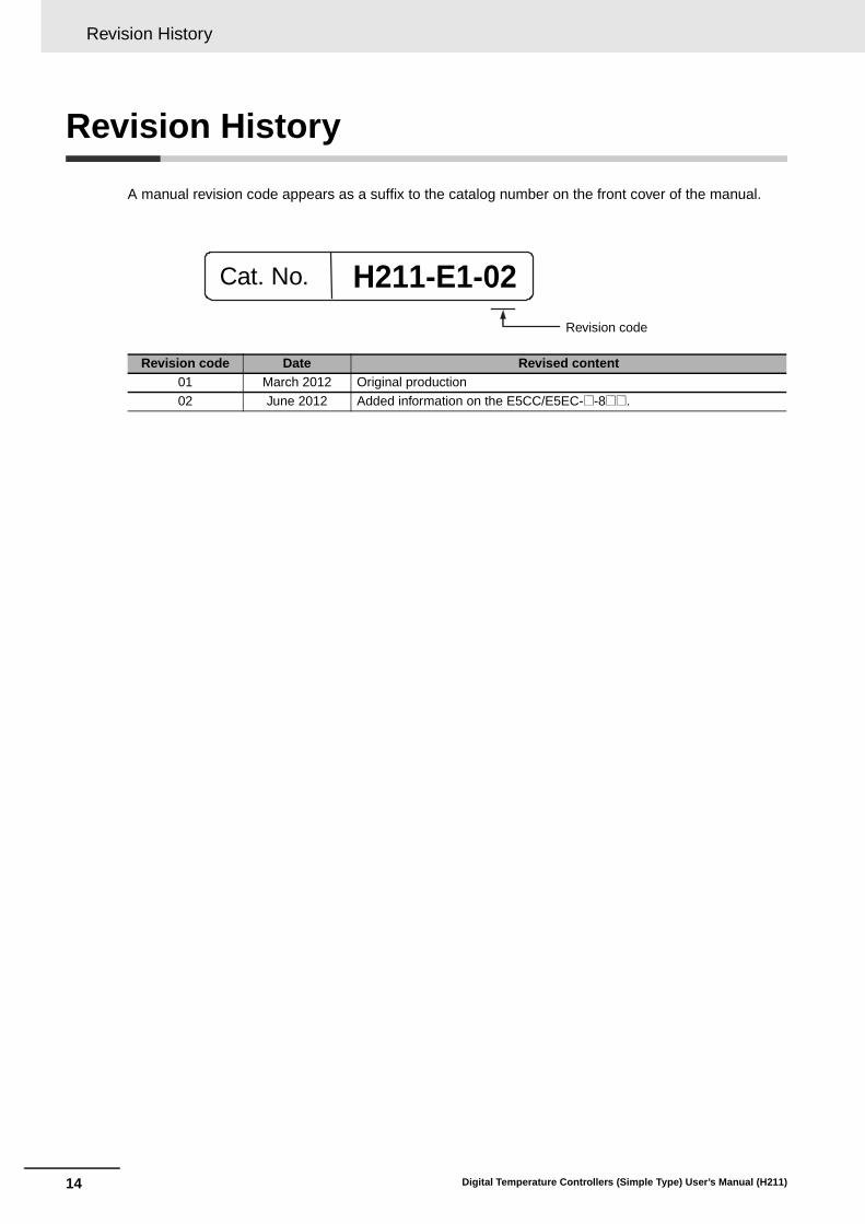
A manual revision code appears as a suffix to the catalog number on the front cover of the manual.
Revision code Date Revised content01 March 2012 Original production
02 June 2012 Added information on the E5CC/E5EC-@-8@@.
H211-E1-02Revision code
Cat. No.

15
Conventions Used in This Manual
Digital Temperature Controllers (Simple Type) User’s Manual (H211)
Conventions Used in This Manual
In this manual, “E5CC/E5EC” or “E5CC-800/E5EC-800” is used to indicated the E5CC/E5EC-@-8@@Simple-type Digital Controllers.
Differences in I/O Configurations
Differences in Main FunctionsThe Simple-type Digital Controllers do not support the following functions.• Remote SP Input• Transfer Output• Simple Program Function• Extraction of Square Root• MV at Stop and Error• MV Change Rate Limit• User Calibration• Logic Operations• Setup Tool: CX-Thermo (EST2-2C-MV4)• USB-Serial Conversion Cable
Differences between Standard-type and Simple-type Digital Controllers
E5CC E5EC
Simple typeStandard
typeSimple type
Standard type
Control outputs 1 and 2
RX (1 relay output) Supported. Supported. Supported. Supported.
QX (1 voltage output (for driving SSR)) Supported. Supported. Supported. Supported.
CX (1 current output) Supported. Supported. Supported. Supported.
QQ (2 voltage outputs (for driving SSRs)) Not supported. Supported. Not supported. Supported.
QR (1 voltage output (for driving SSR) and 1 relay output)
Not supported. Not supported. Supported. Supported.
RR (2 relay outputs) Not supported. Not supported. Supported. Supported.
CC (2 current outputs) Not supported. Not supported. Not supported. Supported.
CR (1 current output and 1 relay output) Not supported. Not supported. Supported. Not supported.
No. of auxiliary outputs
0 Not supported. Supported. Not supported. Not supported.
2 Supported. Supported. Supported. Supported.
3 Not supported. Supported. Not supported. Not supported.
4 Not supported. Not supported. Not supported. Supported.
Power supply voltage
100 to 240 VAC Supported. Supported. Supported. Supported.
24 VAC/DC Supported. Supported. Supported. Supported.
Terminal type Screw terminals Supported. Supported. Supported. Supported.
Screw terminals (with cover) Not supported. Supported. Not supported. Supported.
Input type Universal input Supported. Supported. Supported. Supported.
Option Event inputs Supported. Supported. Supported. Supported.
Communications (RS-485) Supported. Supported. Supported. Supported.
Remote SP input Not supported. Supported. Not supported. Supported.
HB alarm and HS alarm Supported. Supported. Supported. Supported.
Transfer output Not supported. Supported. Not supported. Supported.
Top-panel Setup Tool port Not supported. Supported. Not supported. Supported.
Front-panel Setup Tool port Not supported. Not supported. Not supported. Supported.

Conventions Used in This Manual
16 Digital Temperature Controllers (Simple Type) User’s Manual (H211)
The following abbreviations are used in parameter names, figures, and other descriptions. Theseabbreviations mean the following:
* “EU” stands for Engineering Unit. EU is used as the minimum unit for engineering units such as °C, m, and g.The size of the EU depends on the input type. For example, when the input temperature setting range is −200to 1,300°C, 1 EU is 1°C, and when the input temperature setting range is −20.0 to 500.0°C, 1 EU is 0.1°C.For analog inputs, the size of the EU depends on the decimal point position of the scaling setting, and 1 EU isthe minimum scaling unit.
The following tables show the correspondence between the symbols displayed on the displays andalphabet characters.
Model Notation
Event inputs CommunicationsHB alarm and HS
alarmE5CC/EC-@-800 --- --- ---E5CC-@-801 2 --- 1
E5CC-@-802 --- RS-485 1
E5CC/EC-@-804 2 RS-485 ---E5EC-@-808 2 RS-485 1
E5EC-@-810 4 --- 1
Meanings of Abbreviations
Symbol TermPV Process value
SP Set pointSV Set value
AT Auto-tuning
ST Self-tuningEU Engineering unit*
LBA Loop burnout alarm
HB Heater burnout
HS Heater short
How to Read Display Symbols
a b c d e f g h i j k l m
A B C D E F G H I J K L M
n o p q r s t u V w x y z
N O P Q R S T U V W X Y Z

17
Conventions Used in This Manual
Digital Temperature Controllers (Simple Type) User’s Manual (H211)
The following manual is also related to the E5CC/E5EC.
How This Manual is Organized
Goal Related sections ContentsLearning about the appearance, features, functions, and model numbers of the E5CC/E5EC
Section 1 Introduction This section shows the appearance and describes the features, functions, and model numbers of the E5CC/E5EC.
Setting up the E5CC/E5EC Section 2 Preparations This section describes the steps that are required before turning ON the power supply to the E5CC/E5EC (including installation, terminal usage, wiring, and isolation/insulation block diagram).
Learning the basic procedures from turning ON the power supply to the E5CC/E5EC to starting actual operation
Section 3 Part Names and Basic Procedures
This section describes the basic procedures from turning ON the power supply to the E5CC/E5EC to starting actual operation. It also gives the names of the parts of the E5CC/E5EC. This section serves as a basic tutorial for first-time users of the E5CC/E5EC.
Learning the specifications and parameters of the E5CC/E5EC
Appendices The appendices list the specifications and parameters of the E5CC/E5EC.
Related Manuals
Manual name Cat. No. ContentsE5CC/E5EC Digital Temperature Controllers User’s Manual
H174 This is the user’s manual for the E5CC/E5EC Series. Refer to this manual for detailed specifications of the functions of the E5CC/E5EC-800 Simple-type Digital Controllers.
E5CC/E5EC Digital Temperature Controllers Communications Manual
H175 This manual describes the command text and communications procedures to use the CompoWay/F and Modbus-RTU protocols for serial communications between the E5CC/E5EC and a host device (e.g., a PLC).
Conventions Used in This Manual
18 Digital Temperature Controllers (Simple Type) User’s Manual (H211)

19
Sections in this Manual
Digital Temperature Controllers (Simple Type) User’s Manual (H211)
1
2
3
A
I
1
2
3
A
I
Introduction
Preparations
Part Names and Basic Procedures
Appendices
Index
Sections in this Manual
20 Digital Temperature Controllers (Simple Type) User’s Manual (H211)
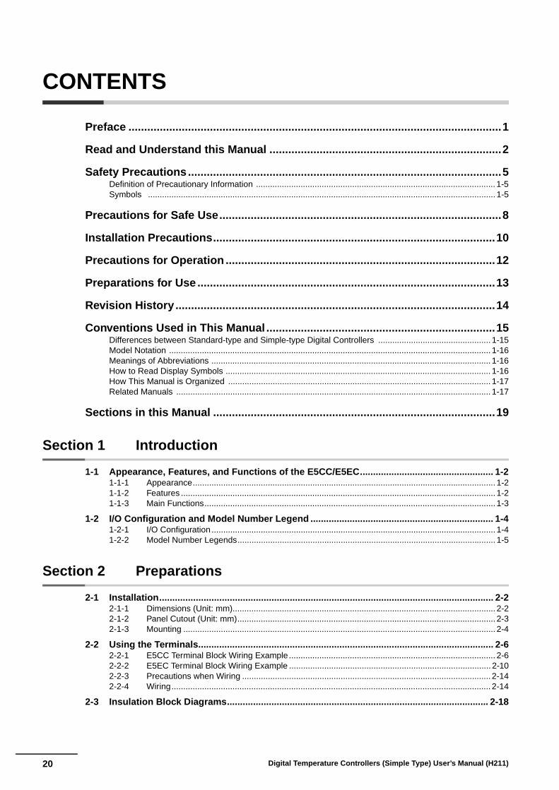
CONTENTS
Preface .......................................................................................................................1
Read and Understand this Manual ..........................................................................2
Safety Precautions....................................................................................................5Definition of Precautionary Information ...................................................................................................... 1-5Symbols .................................................................................................................................................... 1-5
Precautions for Safe Use..........................................................................................8
Installation Precautions..........................................................................................10
Precautions for Operation ......................................................................................12
Preparations for Use ...............................................................................................13
Revision History ......................................................................................................14
Conventions Used in This Manual .........................................................................15Differences between Standard-type and Simple-type Digital Controllers ................................................ 1-15Model Notation ......................................................................................................................................... 1-16Meanings of Abbreviations ....................................................................................................................... 1-16How to Read Display Symbols ................................................................................................................. 1-16How This Manual is Organized ................................................................................................................ 1-17Related Manuals ...................................................................................................................................... 1-17
Sections in this Manual ..........................................................................................19
Section 1 Introduction
1-1 Appearance, Features, and Functions of the E5CC/E5EC................................................... 1-21-1-1 Appearance................................................................................................................................. 1-21-1-2 Features ...................................................................................................................................... 1-21-1-3 Main Functions............................................................................................................................ 1-3
1-2 I/O Configuration and Model Number Legend ...................................................................... 1-41-2-1 I/O Configuration ......................................................................................................................... 1-41-2-2 Model Number Legends.............................................................................................................. 1-5
Section 2 Preparations
2-1 Installation................................................................................................................................ 2-22-1-1 Dimensions (Unit: mm)................................................................................................................ 2-22-1-2 Panel Cutout (Unit: mm).............................................................................................................. 2-32-1-3 Mounting ..................................................................................................................................... 2-4
2-2 Using the Terminals................................................................................................................. 2-62-2-1 E5CC Terminal Block Wiring Example........................................................................................ 2-62-2-2 E5EC Terminal Block Wiring Example ...................................................................................... 2-102-2-3 Precautions when Wiring .......................................................................................................... 2-142-2-4 Wiring........................................................................................................................................ 2-14
2-3 Insulation Block Diagrams.................................................................................................... 2-18

21Digital Temperature Controllers (Simple Type) User’s Manual (H211)
Section 3 Part Names and Basic Procedures
3-1 Basic Application Flow ........................................................................................................... 3-2
3-2 Power ON.................................................................................................................................. 3-3
3-3 Part Names, Part Functions, and Setting Levels .................................................................. 3-43-3-1 Part Names and Functions ......................................................................................................... 3-43-3-2 Entering Numeric Values ............................................................................................................ 3-73-3-3 Setting Levels ............................................................................................................................. 3-83-3-4 E5CC/E5EC Setting Levels ........................................................................................................ 3-9
3-4 Procedures after Turning ON the Power Supply................................................................. 3-133-4-1 Basic Flow of Operations.......................................................................................................... 3-133-4-2 Basic Procedure ....................................................................................................................... 3-13
Section A Appendices
A-1 Specifications ..........................................................................................................................A-2A-1-1 Ratings........................................................................................................................................A-2A-1-2 Characteristics ............................................................................................................................A-3A-1-3 Rating and Characteristics of Options ........................................................................................A-4A-1-4 Waterproof Packing ....................................................................................................................A-4
A-2 Current Transformer (CT)........................................................................................................A-5A-2-1 Specifications..............................................................................................................................A-5A-2-2 Dimensions (Unit: mm) ...............................................................................................................A-5
A-3 Error Displays ..........................................................................................................................A-6
A-4 Troubleshooting.......................................................................................................................A-9
A-5 Parameter Operation Lists....................................................................................................A-12A-5-1 Operation Level.........................................................................................................................A-12A-5-2 Adjustment Level ......................................................................................................................A-13A-5-3 Initial Setting Level.................................................................................................................... A-14A-5-4 Manual Control Level ................................................................................................................A-17A-5-5 Advanced Function Setting Level .............................................................................................A-17A-5-6 Protect Level .............................................................................................................................A-19A-5-7 Communications Setting Level .................................................................................................A-20
A-6 Sensor Input Setting Range, Indication Range, Control Range........................................A-21
A-7 Setting Levels Diagram.........................................................................................................A-22
A-8 Parameter Flow ......................................................................................................................A-24
Index

22 Digital Temperature Controllers (Simple Type) User’s Manual (H211)

1 - 1Digital Temperature Controllers (Simple Type) User’s Manual (H211)
1
1-1 Appearance, Features, and Functions of the E5CC/E5EC . . . . . . . . . . . . . 1-21-1-1 Appearance . . . . . . . . . . . . . . . . . . . . . . . . . . . . . . . . . . . . . . . . . . . . . . . . . . . . 1-21-1-2 Features . . . . . . . . . . . . . . . . . . . . . . . . . . . . . . . . . . . . . . . . . . . . . . . . . . . . . . 1-21-1-3 Main Functions . . . . . . . . . . . . . . . . . . . . . . . . . . . . . . . . . . . . . . . . . . . . . . . . . 1-3
1-2 I/O Configuration and Model Number Legend . . . . . . . . . . . . . . . . . . . . . . . 1-41-2-1 I/O Configuration . . . . . . . . . . . . . . . . . . . . . . . . . . . . . . . . . . . . . . . . . . . . . . . . 1-41-2-2 Model Number Legends . . . . . . . . . . . . . . . . . . . . . . . . . . . . . . . . . . . . . . . . . . 1-5
Introduction

1 Introduction
1 - 2 Digital Temperature Controllers (Simple Type) User’s Manual (H211)
1-1 Appearance, Features, and Functions of the E5CC/E5EC
This section compares the features of the E5CC/E5EC with the previous E5CN/E5EN Controllers.
Input sampling cycle: 50 msControl period: 0.1 s and 0.2 s have been added.Integral/differential time unit: Setting in increments of 0.1 s has been added.
Universal input: The input sensor can be selected freely from the following for any model of the E5CCor E5EC: Thermocouple, resistance thermometer, ES1B Infrared Temperature Sen-sor, current, and voltage.
Digit shift: When setting the SP or other parameters, you can use a Shift Key (assigned to the PF Key)to shift the digit that is being set to aid changing the set values.
1-1-1 Appearance
• A stylish design that gives a new look to control panels.
• Large display characters and white backlight for better visibility.
• A compact size to help downsize control panels.• Much faster sampling and greater expandability than expected
in this class of Controller.
• Even easier to use than previous models.
1-1-2 Features
High-speed Control Capability
Universal Input Capability
Easier Numeric Inputs with a Digit Shift Key
E5CC-800 E5EC-800

1 - 3
1 Introduction
Digital Temperature Controllers (Simple Type) User’s Manual (H211)
1-1 Ap
pearan
ce, Featu
res, and
Fu
nctio
ns o
f the E
5CC
/E5E
C
1
1-1-3 Main F
unctions
This section introduces the main E5CC/E5EC functions. For details on particular functions and how touse them, refer to Section 3 Part Names and Basic Procedures and following sections.
Input Sensor TypesYou can connect the following sensors and signals to the universal input.
Control Outputs• A control output can be a relay, voltage (for driving SSR), or current output, depending on the
model.
Adjusting PID Constants• You can easily set the optimum PID constants by performing AT (auto-tuning) with the limit cycle
method or by performing ST (self-tuning) with the step response method.
AlarmsStandard Alarms• You can output an alarm when the deviation, process value, set point, or manipulated value
reaches a specified value.• You can also output alarms for the PV rate of change and for loop burnouts.• If necessary, a more comprehensive alarm function can be achieved by setting a standby
sequence, alarm hysteresis, auxiliary output close in alarm/open in alarm, alarm latch, alarm ONdelay, and alarm OFF delay.
HB and HS Alarms• With models with the optional HB and HS alarms, you can detect heater burnout and heater short
alarms based on CT inputs.
Integrated Alarm• You can output an integrated alarm if a standard alarm, HB alarm, or HS alarm turns ON.
Event Inputs• With any E5CC/E5EC model that supports event inputs, you can use external contact or
non-contact inputs to achieve any of the following functions: Switching set points (Multi-SP No.Switch, 8 points max.), switching RUN/STOP, switching between automatic and manual operation,inverting direct/reverse operation, 100% AT execute/cancel, 40% AT execute/cancel, settingchange enable/disable, communications write enable/disable, and canceling the alarm latch.
1-1-3 Main Functions
Thermocouple: K, J, T, E, L, U, N, R, S, B, W, PLII
Resistance thermometer: Pt100, JPt100Infrared temperature sensor: ES1B
10 to 70°C, 60 to 120°C, 115 to 165°C, 140 to 260°CCurrent input: 4 to 20 mA DC, 0 to 20 mA DCVoltage input: 1 to 5 VDC, 0 to 5 V DC, 0 to 10 V DC

1 Introduction
1 - 4 Digital Temperature Controllers (Simple Type) User’s Manual (H211)
1-2 I/O Configuration and Model Number Legend
Note: Not all models support these functions. For details, refer to 1-2-2 Model Number Legends.
1-2-1 I/O Configuration
*Functions can be assigned individually for each output by changing the set values for the Control Output 1 and 2 Assignments and the Auxiliary Output 1 and 2 Assignments in the parameters in the advanced function setting level.
E5CC/E5EC
Auxiliary outputs 1 and 2
• Input type • Input shift
• Input filter • Moving average
• Analog scaling
Input signals
• Direct/reverse • Auto/manual
• Linear current • Voltage output(for driving SSR) • Relay
Outputs
PV
Manipulated value (MV)
Limit
Output signals
A: 100 to 240 VACorD: 24 VAC/DC
Multi-SP
Inputs
Set point (SP)
Control
Power supply
• Relay
Control output 1
Contact status
Operation
Process value (PV) input • Thermocouple • Resistance thermometer • Infrared Temperature Sensor • Analog input (current/voltage)
• Relay
Control output 2
• PID or • ON/OFF control
Heating/cooling
*
*
*
SP
• SP ramp
• Set point limiter
Automatic setting of PID constants with AT or ST
• MV limit
• Standard control or • Heating/cooling
control
Alarms
Event inputs (EV1 to EV4) • External inputs(contact or non-contact input)
• Standard alarms (alarms 1 to 4) • HB alarm • HS alarm • Input error (S.ERR)
• Integrated alarm
• RUN status
CT inputInput voltage from CT
• RUN/STOP switching • Auto/manual selection
• 100% AT execute/cancel • 40% AT execute/cancel
• Alarm latch cancel • Multi-SP No.
• Invert direct/reverse operation
• Setting change enable/disable
• Communications write enable/disable
• RS-485
• CompoWay/F • Modbus-RTUCommunications
• HB alarm • HS alarm
1 - 5
1 Introduction
Digital Temperature Controllers (Simple Type) User’s Manual (H211)
1-2 I/O C
on
figu
ration
and
Mo
del
Nu
mb
er Leg
end
1
1-2-2 Model N
umber Legends
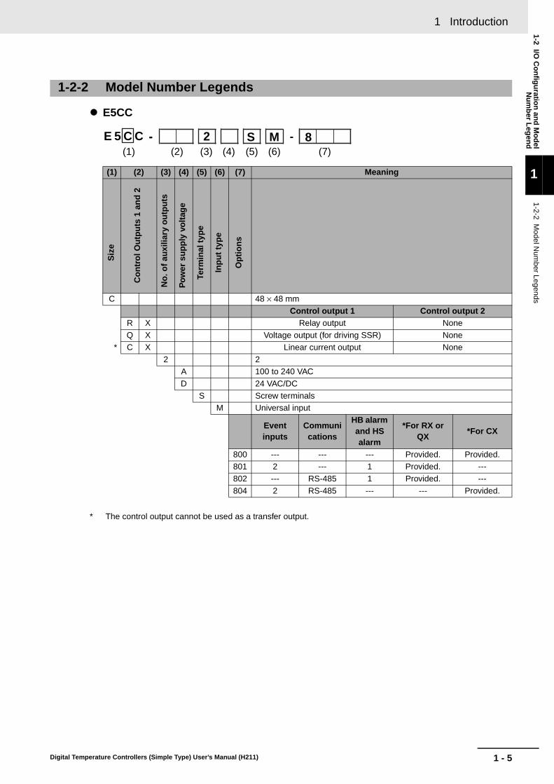
E5CC
* The control output cannot be used as a transfer output.
1-2-2 Model Number Legends
(1) (2) (3) (4) (5) (6) (7) Meaning
C 48 × 48 mm
Control output 1 Control output 2R X Relay output None
Q X Voltage output (for driving SSR) None
* C X Linear current output None
2 2A 100 to 240 VAC
D 24 VAC/DC
S Screw terminalsM Universal input
Event inputs
Communications
HB alarm and HS alarm
*For RX or QX
*For CX
800 --- --- --- Provided. Provided.801 2 --- 1 Provided. ---
802 --- RS-485 1 Provided. ---
804 2 RS-485 --- --- Provided.
-- -E 5 C C - -(1) (2) (3) (4) (5) (6) (7)
2 S M 8
Siz
e
Co
ntr
ol O
utp
uts
1 a
nd
2
No
. of
auxi
liary
ou
tpu
ts
Pow
er s
up
ply
vo
ltag
e
Term
inal
typ
e
Inp
ut
typ
e
Op
tio
ns

1 Introduction
1 - 6 Digital Temperature Controllers (Simple Type) User’s Manual (H211)
E5EC
* The control output cannot be used as a transfer output.
(1) (2) (3) (4) (5) (6) (7) Meaning
E 48 × 96 mm
Control output 1 Control output 2
R X Relay output None
Q X Voltage output (for driving SSR) None
* C X Linear current output None
Q R Voltage output (for driving SSR) Relay output
R R Relay output Relay output
* C R Linear current output Relay output
2 2
A 100 to 240 VAC
D 24 VAC/DC
S Screw terminals
M Universal input
Event inputs
Communications
HB alarm and HS alarm
*For RX, QX or CX
*For RR or QR
*For CR
800 --- --- --- Provided. Provided. Provided.804 2 RS-485 --- --- --- Provided.808 2 RS-485 1 --- Provided. ---810 4 --- 1 --- Provided. ---
-- -E 5 E C - -
(1) (2) (3) (4) (5) (6) (7)2 S M 8
Siz
e
Co
ntr
ol O
utp
uts
1 a
nd
2
No
. of
auxi
liary
ou
tpu
ts
Po
wer
su
pp
ly v
olt
age
Term
inal
typ
e
Inp
ut
typ
e
Op
tio
ns
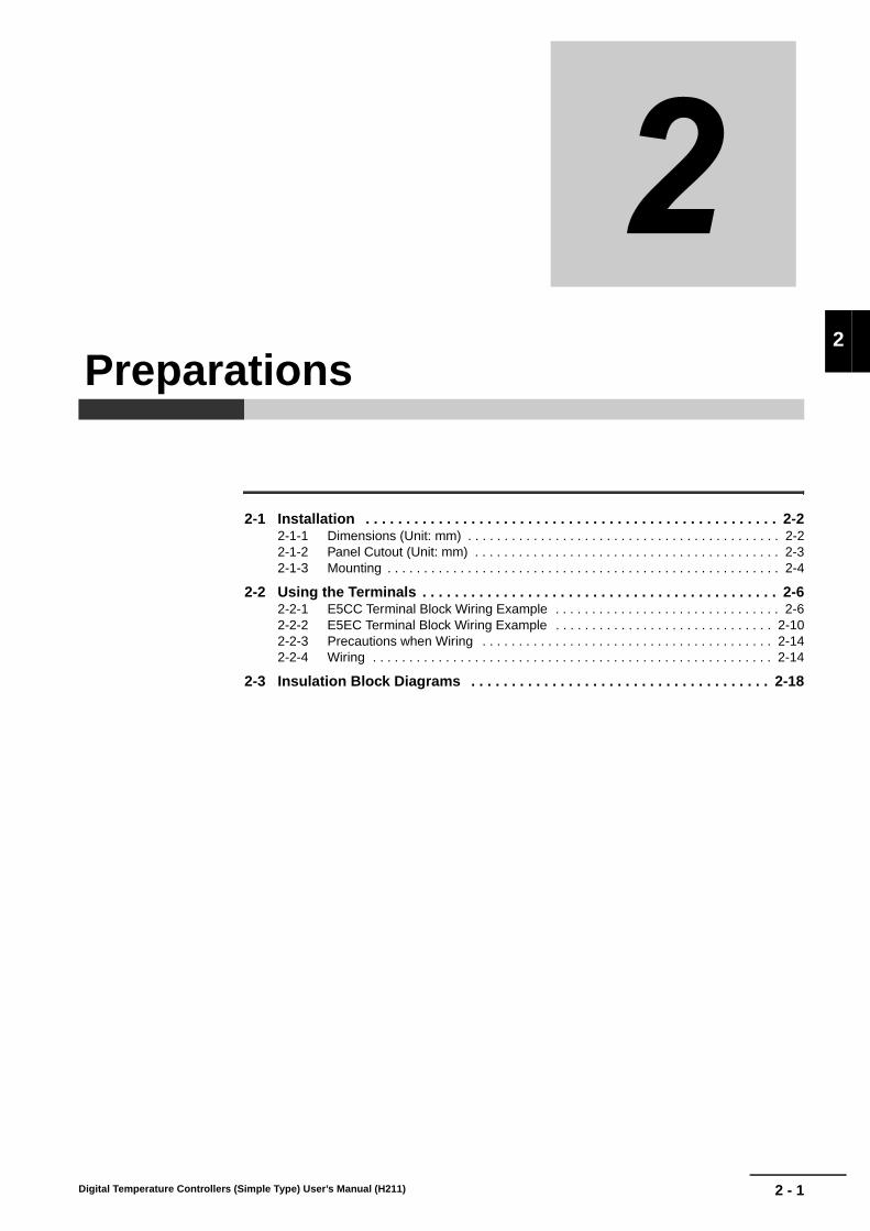
2 - 1Digital Temperature Controllers (Simple Type) User’s Manual (H211)
2
2-1 Installation . . . . . . . . . . . . . . . . . . . . . . . . . . . . . . . . . . . . . . . . . . . . . . . . . . . 2-22-1-1 Dimensions (Unit: mm) . . . . . . . . . . . . . . . . . . . . . . . . . . . . . . . . . . . . . . . . . . . 2-22-1-2 Panel Cutout (Unit: mm) . . . . . . . . . . . . . . . . . . . . . . . . . . . . . . . . . . . . . . . . . . 2-32-1-3 Mounting . . . . . . . . . . . . . . . . . . . . . . . . . . . . . . . . . . . . . . . . . . . . . . . . . . . . . . 2-4
2-2 Using the Terminals . . . . . . . . . . . . . . . . . . . . . . . . . . . . . . . . . . . . . . . . . . . . 2-62-2-1 E5CC Terminal Block Wiring Example . . . . . . . . . . . . . . . . . . . . . . . . . . . . . . . 2-62-2-2 E5EC Terminal Block Wiring Example . . . . . . . . . . . . . . . . . . . . . . . . . . . . . . 2-102-2-3 Precautions when Wiring . . . . . . . . . . . . . . . . . . . . . . . . . . . . . . . . . . . . . . . . 2-142-2-4 Wiring . . . . . . . . . . . . . . . . . . . . . . . . . . . . . . . . . . . . . . . . . . . . . . . . . . . . . . . 2-14
2-3 Insulation Block Diagrams . . . . . . . . . . . . . . . . . . . . . . . . . . . . . . . . . . . . . 2-18
Preparations

2 Preparations
2 - 2 Digital Temperature Controllers (Simple Type) User’s Manual (H211)
2-1 Installation
E5CC
E5EC
2-1-1 Dimensions (Unit: mm)
(64)
58
604148 × 48 44.8 × 44.8
44
91
48
96
1604
(64)11
0

2 - 3
2 Preparations
Digital Temperature Controllers (Simple Type) User’s Manual (H211)
2-1 Installatio
n
2
2-1-2 Panel C
utout (Unit: m
m)
E5CC
• Waterproofing is not possible when group mounting several Controllers.• The recommended panel thickness is 1 to 5 mm for the E5CC.• Controllers must not be closely mounted vertically. (Observe the recommended mounting space
limits.)• When group mounting several Controllers, ensure that the surrounding temperature does not exceed
the ambient operating temperature listed in the specifications.
E5EC
• Waterproofing is not possible when group mounting several Controllers.• The recommended panel thickness is 1 to 8 mm for the E5EC.• Controllers must not be closely mounted vertically. (Observe the recommended mounting space
limits.)• When group mounting several Controllers, ensure that the surrounding temperature does not exceed
the ambient operating temperature listed in the specifications.
2-1-2 Panel Cutout (Unit: mm)60
min
.
+1.0 0
Individual Mounting Group Mounting(48 × number of Units − 2.5) 45+0.6
0
45+
0.6
0
45+
0.6
0
Individual Mounting
120
min
.
+1.0 0
Group Mounting*(48 × number of Units − 2.5) 45+0.6
0
92+
0.8
0
92+
0.8
0

2 Preparations
2 - 4 Digital Temperature Controllers (Simple Type) User’s Manual (H211)
E5CCThere are two models of Terminal Covers that you can use with the E5CC.
Mounting to the Panel
(1) For waterproof mounting, waterproof packing must be installed on the Controller.Waterproofing is not possible when group mounting several Controllers. Waterproofpacking is not necessary when there is no need for the waterproofing function.
(2) Insert the E5CC into the mounting hole in the panel.
(3) Push the adapter from the terminals up to the panel, and temporarily fasten the E5CC.
(4) Tighten the two fastening screws on the adapter. Alternately tighten the two screws little bylittle to maintain a balance. Tighten the screws to a torque of 0.29 to 0.39 N·m.
Mounting the Terminal CoverSlightly bend the E53-COV23 Terminal Cover to attach it to the terminal block as shown in the followingdiagram. The Terminal Cover cannot be attached in the opposite direction. Or, you can use the E53-COV17Terminal Cover. Make sure that the “UP” mark is facing up, and then attach the E53-COV17 Terminal Cover tothe holes on the top and bottom of the Digital Controller.
2-1-3 Mounting
Adapter
Waterproof packing
Panel
E53-COV17Terminal Cover (Sold separately.)
Adapter
E53-COV23Terminal Cover
Terminal Cover(E53-COV17) (Sold separately.)
• E53-COV17 • E53-COV23
Enlarged Illustration of Terminal Section
Adapter

2 - 5
2 Preparations
Digital Temperature Controllers (Simple Type) User’s Manual (H211)
2-1 Installatio
n
2
2-1-3 Mounting
E5EC
Mounting to the Panel
(1) For waterproof mounting, waterproof packing must be installed on the Controller.Waterproofing is not possible when group mounting several Controllers. Waterproofpacking is not necessary when there is no need for the waterproofing function.
(2) Insert the E5EC into the mounting hole in the panel.
(3) Push the adapter from the terminals up to the panel, and temporarily fasten the E5EC.
(4) Tighten the two fastening screws on the adapter. Alternately tighten the two screws little bylittle to maintain a balance. Tighten the screws to a torque of 0.29 to 0.39 N·m.
Mounting the Terminal CoverSlightly bend the E53-COV24 Terminal Cover to attach it to the terminal block as shown in the followingdiagram. The Terminal Cover cannot be attached in the opposite direction.
E53-COV24Terminal Cover
Adapter
Waterproof packing
Panel
E53-COV24Terminal Cover
Adapter
Slightly bend the E53-COV24 Terminal Cover in the direction shown by the arrows to attach it to the terminal block.
Enlarged Illustration of Terminal Section

2 Preparations
2 - 6 Digital Temperature Controllers (Simple Type) User’s Manual (H211)
2-2 Using the Terminals
The terminal arrangements of the E5CC/E5EC are described in this section.
Terminal ArrangementThe terminals block of the E5CC is divided into five types of terminals: control output 1, sensor input,auxiliary outputs, input power supply, and options.
Precautions for Correct Use
When you purchase the Digital Controller, it will be set for a K thermocouple (input type = 5) bydefault. If a different sensor is used, an input error (s.err) will occur. Check the setting of theInput Type parameter.
Model NumbersThe specification for control output 1 is given in the following location in the model number.
2-2-1 E5CC Terminal Block Wiring Example
Control Output 1
Code Output type SpecificationRX 1 relay output 250 VAC, 3 A (resistive load)QX 1 voltage output (for driving SSR) 12 VDC, 21 mA
CX 1 current output 4 to 20 mA DC or 0 to 20 mA DC with load of 500 Ω max.
G
H
I
J
K
L
A
B
C
D
E
F
Control output 1
Sensor input
Auxiliary outputs
Input power supply
Not used.
M
N
O
P
Q
R
Options
E5CC-@@ 2 @ S M-8@@
Control output 1

2 - 7
2 Preparations
Digital Temperature Controllers (Simple Type) User’s Manual (H211)
2-2 Usin
g th
e Termin
als
2
2-2-1 E5C
C Term
inal Block W
iring Exam
ple
Terminal DetailsDo not connect anything to the terminals that are shaded gray.
Model NumbersAll E5CC models have universal sensor inputs, so the code in the model number is always “M.”
Terminal DetailsDo not connect anything to the terminals that are shaded gray.
Precautions for Correct Use
When complying with EMC standards, the line connecting the sensor must be 30 m or less. If thecable length exceeds 30 m, compliance with EMC standards will not be possible.
RX QX
CX
Sensor Input
TC (thermocouple)Pt (resistance thermometer)
I (current) V (voltage)
A
C
BRelay outputControl output 1
A
C
B+−
Control output 1 Voltage output (for driving SSR)
A
C
B
+
−Control output 1 Current output
E5CC-@@ 2 @ S M-8@@
Sensor input
D
F
E−
+
E
D
F
A
B
B
+
−E
D
F
mA
+
−E
D
FV

2 Preparations
2 - 8 Digital Temperature Controllers (Simple Type) User’s Manual (H211)
Model NumbersAll E5CC models have two auxiliary outputs, so the code in the model number is always “2.”
Terminal Details
Model NumbersThe input power supply specification of the E5CC is given in the following location in the model number.
Terminal Details
Auxiliary Outputs
Code Auxiliary outputs Specification2 2 auxiliary outputs SPST-NO, 250 VAC, 3 A
Model with 2 auxiliary outputs
Input Power Supply
Code Specification Power consumptionA 100 to 240 VAC, 50/60 Hz Option number 800: 5.2 VA max.
Other option numbers: 6.5 VA max.D 24 VAC, 50/60 Hz
24 VDC (no polarity)Option number 800: 3.1 VA max./1.6 W max.Other option numbers: 4.1 VA max./2.3 W max.
100 to 240 VAC 24 VAC/DC
E5CC-@@ 2 @ S M-8@@
No. of auxiliary outputs
G
H
I
J
Auxiliary output 2
Auxiliary output 1
E5CC-@@ 2 @ S M-8@@
Input power supply
L
K
(No polarity)
L
K

2 - 9
2 Preparations
Digital Temperature Controllers (Simple Type) User’s Manual (H211)
2-2 Usin
g th
e Termin
als
2
2-2-1 E5C
C Term
inal Block W
iring Exam
ple
Model NumbersThe options specification of the E5CC is given in the following location in the model number.
Terminal DetailsDo not connect anything to the terminals that are shaded gray.
Options
Code Specification Remarks800 None801 Event inputs 1 and 2, and
CT1
802 Communications (RS-485) and CT1
The communications protocol is CompoWay/F or Modbus-RTU.
804 Communications (RS-485), and event inputs 3 and 4
The communications protocol is CompoWay/F or Modbus-RTU.
801 802
804
E5CC-@@ @ @ @ M-8@@
Options
13
EV1
EV2
CT1
Event inputs
CT
14
18
15
16
17
B(+)
A(−)
RS-485
CT1CT
Communications13
14
18
16
17
15
EV3
EV4
B(+)
A(−)
RS-485
Event inputs
Communications13
14
15
18
16
17
2 Preparations
2 - 10 Digital Temperature Controllers (Simple Type) User’s Manual (H211)
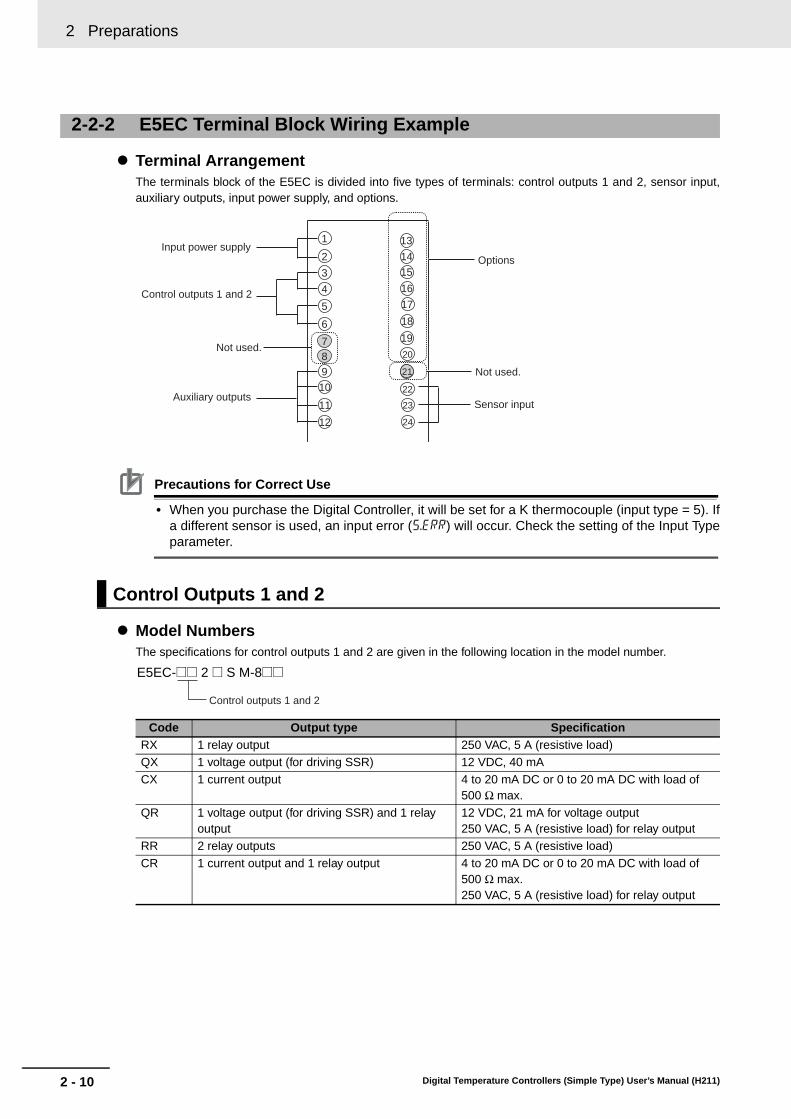
Terminal ArrangementThe terminals block of the E5EC is divided into five types of terminals: control outputs 1 and 2, sensor input,auxiliary outputs, input power supply, and options.
Precautions for Correct Use
• When you purchase the Digital Controller, it will be set for a K thermocouple (input type = 5). Ifa different sensor is used, an input error (s.err) will occur. Check the setting of the Input Typeparameter.
Model NumbersThe specifications for control outputs 1 and 2 are given in the following location in the model number.
2-2-2 E5EC Terminal Block Wiring Example
Control Outputs 1 and 2
Code Output type SpecificationRX 1 relay output 250 VAC, 5 A (resistive load)QX 1 voltage output (for driving SSR) 12 VDC, 40 mA
CX 1 current output 4 to 20 mA DC or 0 to 20 mA DC with load of 500 Ω max.
QR 1 voltage output (for driving SSR) and 1 relay output
12 VDC, 21 mA for voltage output250 VAC, 5 A (resistive load) for relay output
RR 2 relay outputs 250 VAC, 5 A (resistive load)
CR 1 current output and 1 relay output 4 to 20 mA DC or 0 to 20 mA DC with load of 500 Ω max. 250 VAC, 5 A (resistive load) for relay output
Input power supply
Control outputs 1 and 2
Auxiliary outputsSensor input
Not used.
1
2
3
4
5
6
12
11
7
98
10
16
17
18
13
14
15
22
23
24
19
20
21
Not used.
Options
Control outputs 1 and 2
E5EC-@@ 2 @ S M-8@@

2 - 11
2 Preparations
Digital Temperature Controllers (Simple Type) User’s Manual (H211)
2-2 Usin
g th
e Termin
als
2
2-2-2 E5E
C Term
inal Block W
iring Exam
ple
Terminal DetailsDo not connect anything to the terminals that are shaded gray.
Model NumbersAll E5EC models have universal sensor inputs, so the code in the model number is always “M.”
Terminal DetailsDo not connect anything to the terminals that are shaded gray.
Precautions for Correct Use
When complying with EMC standards, the line connecting the sensor must be 30 m or less. If thecable length exceeds 30 m, compliance with EMC standards will not be possible.
RX QX CX
QR RR CR
Sensor Input
TC (thermocouple)Pt (resistance thermometer)
I (current) V (voltage)
C
E
D
F
Relay outputControl output 1 +−
C
E
D
F
Voltage output (for driving SSR)
Control output 1 +C
E
D
F
Current outputControl output 1−
Relay output
C
E
D
F
+ Voltage output (for driving SSR)
Control output 1
Control output 2
−
C
E
D
FRelay output
Relay outputControl output 1
Control output 2
C
D+ Current outputControl output 1−
E
FRelay outputControl output 2
Sensor input
E5EC-@@ 2 @ S M-8@@
−
+
22
23
24
A
B
B
22
23
24
+
−
mA22
23
24 +
−
V
22
23
24
2 Preparations
2 - 12 Digital Temperature Controllers (Simple Type) User’s Manual (H211)
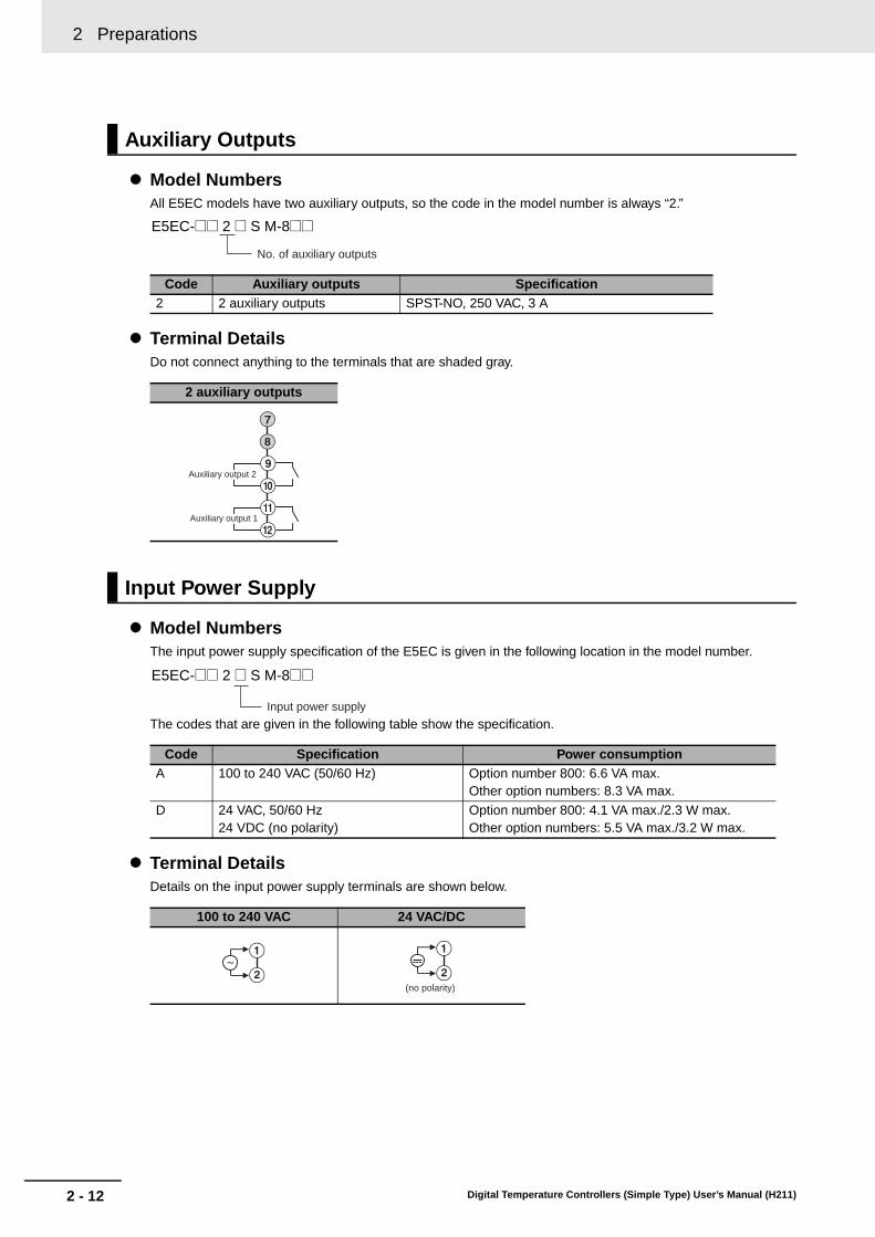
Model NumbersAll E5EC models have two auxiliary outputs, so the code in the model number is always “2.”
Terminal DetailsDo not connect anything to the terminals that are shaded gray.
Model NumbersThe input power supply specification of the E5EC is given in the following location in the model number.
The codes that are given in the following table show the specification.
Terminal DetailsDetails on the input power supply terminals are shown below.
Auxiliary Outputs
Code Auxiliary outputs Specification2 2 auxiliary outputs SPST-NO, 250 VAC, 3 A
2 auxiliary outputs
Input Power Supply
Code Specification Power consumptionA 100 to 240 VAC (50/60 Hz) Option number 800: 6.6 VA max.
Other option numbers: 8.3 VA max.
D 24 VAC, 50/60 Hz24 VDC (no polarity)
Option number 800: 4.1 VA max./2.3 W max.Other option numbers: 5.5 VA max./3.2 W max.
100 to 240 VAC 24 VAC/DC
No. of auxiliary outputs
E5EC-@@ 2 @ S M-8@@
G
H
I
J
K
L
Auxiliary output 2
Auxiliary output 1
Input power supply
E5EC-@@ 2 @ S M-8@@
A
B (no polarity)
A
B

2 - 13
2 Preparations
Digital Temperature Controllers (Simple Type) User’s Manual (H211)
2-2 Usin
g th
e Termin
als
2
2-2-2 E5E
C Term
inal Block W
iring Exam
ple
Model NumbersThe options specification of the E5EC is given in the following location in the model number.
Terminal DetailsDo not connect anything to the terminals that are shaded gray.
Options
Code Specification Remarks800 None804 Communications (RS-485),
and event inputs 1 and 2The communications protocol is CompoWay/F or Modbus-RTU.
808 Communications (RS-485), event inputs 1 and 2, and CT1
The communications protocol is CompoWay/F or Modbus-RTU.
810 Event inputs 1 to 4, and CT1
804 808
810
E5EC-@@ @ @ @ M-8@@
Options
EV1
EV2
B(+)
A(−)
RS-485Communications
Event inputs
19
20
15
16
17
18
13
14
21
B(+)
EV1
EV2
A(−)
RS-485
CT1
Communications
Event inputs
CT19
20
15
16
17
18
13
14
21
EV1
EV2
EV3
EV4
CT1
Event inputs
Event inputs
CT19
20
15
16
17
18
13
14
21

2 Preparations
2 - 14 Digital Temperature Controllers (Simple Type) User’s Manual (H211)
• Separate input leads and power lines in order to prevent external noise.
• Use a shielded, AWG24 to AWG18 (cross-sectional area of 0.205 to 0.823 mm2) twisted-pair cable.The stripping length is 6 to 8 mm.
• Use crimp terminals when wiring the terminals.• Use the suitable wiring material and crimp tools for crimp terminals.• Tighten the terminal screws to a torque of 0.43 to 0.58 N·m.• Use the following types of crimp terminals for M3.0 screws.
In the connection diagrams, the left side of the terminal numbers represents the inside of the Controllerand the right side represents the outside.
Power SupplyPower Consumption
• These models have reinforced insulation between the input power supply, the relay outputs, andother terminals.
InputsRefer to 2-2-1 E5CC Terminal Block Wiring Example or 2-2-2 E5EC Terminal Block Wiring Example for theterminal arrangement. When extending the thermocouple lead wires, be sure to use compensating wires thatmatch the thermocouple type. When extending the lead wires of a resistance thermometer, be sure to use wiresthat have low resistance and keep the resistance of the three lead wires the same.
2-2-3 Precautions when Wiring
2-2-4 Wiring
Input Power SupplyE5CC E5EC
Options No.: 800Options No.:
Not 800Options No.: 800
Options No.: Not 800
100 to 240 VAC, 50/60 Hz 5.2 VA max. 6.5 VA max. 6.6 VA max. 8.3 VA max.24 VAC, 50/60 Hz 3.1 VA max. 4.1 VA max. 4.1 VA max. 5.5 VA max.
24 VDC (no polarity) 1.6 W max. 2.3 W max. 2.3 W max. 3.2 W max.
5.8 mm max.
5.8 mm max.

2 - 15
2 Preparations
Digital Temperature Controllers (Simple Type) User’s Manual (H211)
2-2 Usin
g th
e Termin
als
2
Control Outputs 1 and 2The following diagrams show the applicable outputs and their internal equivalent circuits.
E5CC
E5EC
RX (relay output)QX (voltage output (for
driving SSR))CX (current output)
Output type SpecificationRX Relay output SPST-NO, 250 VAC, 3 A (resistive load), Electrical
durability: 100,000 operations
QX Voltage output (for driving SSR)
PNP, 12 VDC ±20%, 21 mA (with short-circuit protection)
CX Current output 4 to 20 or 0 to 20 mA DC, Load: 500 Ω max., Resolution: Approx. 10,000
RX (relay output)QX (voltage output (for
driving SSR))CX (current output)
RR (2 relay outputs)QR (voltage output (for driving SSR) and relay
output)
CR (current output and relay output)
A
B
+v
+
−GND
LA
B
+v
+
−
LA
B
D
C
+v
+
GNDL
−D
C
+v
+
L
−D
C
D
C
F
E
+v
+
GND
L
D
C
F
E
−
+v
+
L
D
C
F
E
−

2 Preparations
2 - 16 Digital Temperature Controllers (Simple Type) User’s Manual (H211)
Auxiliary Outputs 1 and 2When heating/cooling control is used on the E5CC/E5EC, auxiliary output 2 is the control output for cooling.
Event InputsE5CC/E5EC models with an option number of 801, 804, 808, or 810 have event inputs.
E5CC
E5EC
Output type SpecificationRX Relay output SPST-NO, 250 VAC, 5 A (resistive load),
Electrical durability: 100,000 operationsQX Voltage output (for driving
SSR)PNP, 12 VDC ±20%, 40 mA (with short-circuit protection)
CX Current output 4 to 20 or 0 to 20 mA DC, Load: 500 Ω max., Resolution: Approx. 10,000
RR 2 relay outputs SPST-NO, 250 VAC, 5 A (resistive load), Electrical durability: 100,000 operations
QR Voltage output (for driving SSRs) (control output 1)
PNP, 12 VDC ±20%, 21 mA (with short-circuit protection)
Relay output (control output 2)
SPST-NO, 250 VAC, 5 A (resistive load), Electrical durability: 100,000 operations
CR Current output 4 to 20 or 0 to 20 mA DC, Load: 500 Ω max., Resolution: Approx. 10,000
Relay output SPST-NO, 250 VAC, 5 A (resistive load), Electrical durability: 100,000 operations
Contact inputs Non-contact inputsOption number: 801
Option number: 804
Contact inputs Non-contact inputsOption number: 804, 808
EV1
EV215
13
14 EV1
+
+
EV2
−
15
13
14
EV3
EV418
16
17EV3
EV4+
+
−
18
16
17
EV1
EV218
16
17EV1
EV2+
+
−
18
16
17

2 - 17
2 Preparations
Digital Temperature Controllers (Simple Type) User’s Manual (H211)
2-2 Usin
g th
e Termin
als
2
2-2-4 Wiring
• Use event inputs under the following conditions:• The outflow current is approximately 7 mA.
CT InputE5CC/E5EC models with an option number of 801, 802, 808, or 810 have one CT input.
CommunicationsRS-485E5CC/E5EC models with an option number of 802, 804, 808, or 810 support communications. Connect thecommunications cable to terminals 13 and 14 to use communications with the E5CC/E5EC.
Communications Unit Connection Diagram E5CC/E5EC
• The RS-485 connection can be either one-to-one or one-to-N. A maximum of 32 Units (includingthe host computer) can be connected in one-to-N systems. The maximum total cable length is
500 m. Use a shielded, AWG24 to AWG18 (cross-sectional area of 0.205 to 0.823 mm2)twisted-pair cable.
Option number: 810
Contact input ON: 1 kΩ max., OFF: 100 kΩ min.
No-contact input ON: Residual voltage of 1.5 V max.; OFF: Leakage current of 0.1 mA max.
Contact inputs Non-contact inputs
EV1
EV2
EV3
EV4
18
16
17
15
13
14EV3
EV4
EV1
EV2
+
+
−
+
+
−
18
16
17
15
13
14
No.1413
No.1413
RS-485
E5CC/E5EC (No.1)
RS-485
E5CC/E5EC (No.31)100 Ω
A (−)B (+)
A (−)B (+)
−+
FG
RS-485Host computer
Shield
Terminator (120 Ω, 1/2 W)
Abbreviation Abbreviation
A < B: [1] MarkA > B: [0] Space
Cross-sectional area of conductorAWG24: 0.205 mm2
AWG18: 0.823 mm2

2 Preparations
2 - 18 Digital Temperature Controllers (Simple Type) User’s Manual (H211)
2-3 Insulation Block Diagrams
The insulation block diagram for the E5CC/E5EC is provided in this section.
Sensor input and CT input
Communications and event inputs
Voltage output (for driving SSR) and current output
Relay outputs
Auxiliary output 1
Auxiliary output 2
: Reinforced insulation
: Functional insulation
Power supply

3 - 1Digital Temperature Controllers (Simple Type) User’s Manual (H211)
3
3-1 Basic Application Flow . . . . . . . . . . . . . . . . . . . . . . . . . . . . . . . . . . . . . . . . . 3-2
3-2 Power ON . . . . . . . . . . . . . . . . . . . . . . . . . . . . . . . . . . . . . . . . . . . . . . . . . . . . 3-3
3-3 Part Names, Part Functions, and Setting Levels . . . . . . . . . . . . . . . . . . . . . 3-43-3-1 Part Names and Functions . . . . . . . . . . . . . . . . . . . . . . . . . . . . . . . . . . . . . . . . 3-43-3-2 Entering Numeric Values . . . . . . . . . . . . . . . . . . . . . . . . . . . . . . . . . . . . . . . . . 3-73-3-3 Setting Levels . . . . . . . . . . . . . . . . . . . . . . . . . . . . . . . . . . . . . . . . . . . . . . . . . . 3-83-3-4 E5CC/E5EC Setting Levels . . . . . . . . . . . . . . . . . . . . . . . . . . . . . . . . . . . . . . . 3-9
3-4 Procedures after Turning ON the Power Supply . . . . . . . . . . . . . . . . . . . . 3-133-4-1 Basic Flow of Operations . . . . . . . . . . . . . . . . . . . . . . . . . . . . . . . . . . . . . . . . 3-133-4-2 Basic Procedure . . . . . . . . . . . . . . . . . . . . . . . . . . . . . . . . . . . . . . . . . . . . . . . 3-13
Part Names and Basic Procedures

3 Part Names and Basic Procedures
3 - 2 Digital Temperature Controllers (Simple Type) User’s Manual (H211)
3-1 Basic Application Flow
The following figure shows the basic flow for using the Digital Controller.
Power ON
• Input type
• Control method
• Alarm typeOther parameters
Set the set point.
Set the alarm set values.
Operate with the set values.
*For time-proportional operation.
Set the control hysteresis. Set the control periods* and PID constants.
ON/OFF Control PID Control
Set the input type and other basic settings.
Refer to 3-4 Procedures after Turning ON the Power Supply.

3 - 3
3 Part Names and Basic Procedures
Digital Temperature Controllers (Simple Type) User’s Manual (H211)
3-2 Pow
er ON
3
3-2 Power ON
Operation will start as soon as you turn ON the power supply to the E5CC/E5EC.The following default settings will be used when operation starts.
After the power comes ON, all indicators and displays will light for approximately 1 second, and then theoperation display will appear.The top display will show the PV and the bottom display will show the SP.
• Input type 5: K thermocouple• ON/OFF control• Alarm: Upper-limit alarm*• Set point: 0°C
* If the Controller is equipped with HB/HS alarm detection, it is set bydefault to detect heater alarms.
s.err 0
25 0
C
• Resistance Thermometer Connected or• Temperature Sensor Not Connected
• Thermocouple Connected
SP*The default setting is 0°C.
s.err:An input error is displayed.
The default setting of the input type is for a K thermocouple.
The operation display appears.Operation Level
Power ON
Everything lights for
approx. 1 s.
The PV that is measured by the temperature sensor is displayed.
K Thermocouple Connected: The correct temperature is
displayed.Other Thermocouple Connected: The correct temperature is
not displayed.
If you are not using a K thermocouple, set the Input Type parameter to the correct sensor type in the Initial Setting Level.Refer to step 2 on 3-13.
• Change the setting of the Input Type parameter to a resistance thermometer in the Initial Setting Level.
Or• Connect a temperature sensor.Refer to step 2 on 3-13.

3 Part Names and Basic Procedures
3 - 4 Digital Temperature Controllers (Simple Type) User’s Manual (H211)
3-3 Part Names, Part Functions, and Setting Levels
3-3-1 Part Names and Functions
E5CC
E5EC
Press O Key once to go to Adjustment Level.
Press O Key for at least 3 seconds to go to Initial Setting Level.
Use the M Key to change to another parameter.
Operation indicators No. 1 display
No. 2 display
Temperature unit
Use S Key to change the digit (default setting).
Use the U D Keys to set the parameter.
Front panel
PV or specified parameter
SP or specified parameter value
Operation indicators
Temperature unit
Use S Key to change the digit (default setting).
Use the M Key to change to another parameter.
No. 1 display
No. 2 display
No. 3 display
Press O Key once to go to Adjustment Level.
Press O Key for at least 3 seconds to go to Initial Setting Level.
PV or specified parameter
SP or specified parameter value
Manipulated value or other value
Use the U D Keys to set the parameter.
Front panel

3 - 5
3 Part Names and Basic Procedures
Digital Temperature Controllers (Simple Type) User’s Manual (H211)
3-3 Part N
ames, P
art Fu
nctio
ns, an
d S
etting
Levels
3
3-3-1 Part N
ames and F
unctions
* Any settings that are entered will be ignored.
Displays
Display Name DescriptionE5CC: Top displayE5EC: Top display
No. 1 display Displays the process value or a monitor/setting item.
E5CC: Bottom displayE5EC: Middle display
No. 2 display Displays the set point or the value of a monitor/setting item.
E5CC: NoneE5EC: Bottom display
No. 3 Display (E5EC only)
Displays the manipulated variable, remaining soak time*, multi-SP No., internal SP (ramp SP), or alarm value 1. (The value that is displayed is set in the PV/SP Display Selection parameter in the Advanced Function Setting Level.)
C or F Temperature unit
Displays the temperature unit.
Indicators
Operation indicators Name DescriptionAuxiliary outputs 1 and 2
Each indicator lights when the function that is assigned to the corresponding auxiliary output (1 and 2) is ON.
Control outputs 1 and 2
Each indicator lights when the function that is assigned to the corresponding control output (1 or 2) is ON. (For a current output, the indicator is not lit only for a 0% output.)
Communications writing control
This indicator lights when writing with communications is enabled.
Manual This indicator is lit in Manual Mode.
Stop This indicator is lit while operation is stopped.
AT/ST in progress
This indicator is lit during autotuning.This indicator flashes during self-tuning.
Setting change protection
This indicator is lit while setting change protection is ON.

3 Part Names and Basic Procedures
3 - 6 Digital Temperature Controllers (Simple Type) User’s Manual (H211)
Keys
Key Name Overview Description
O
Level Key Selects the setting level.
The next setting level depends on how long the key is pressed.
• In Operation Level• Press once for less than 1 second to go to
Adjustment Level.• Press for at least 3 seconds to go to Initial Setting
Level.• In Adjustment Level
• Press once for less than 1 second to go to Operation Level.
• Press for at least 3 seconds to go to Initial Setting Level.
• In Initial Setting Level• Press for at least 1 second to go to Operation
Level.• Display amov (Move to Advanced Function
Setting Level) and then enter −169 to go to Advanced Function Setting Level.
M
Mode Key Changes the parameter that is displayed within a setting level.
• Press once to go to the next parameter.• Hold to go to the previous parameter.
D
U
Down Key and Up Key
Set the value. • Hold the key to increment or decrement the value quickly.
• Any changes in settings are applied at the following times:
• After 3 seconds elapse• When the M Key is pressed• When the level is changed with the O Key
S
Shift Key (PF Key) Operates as a user-defined function key.
• Press the S to select the digit to change.You can change the PF Setting parameter to assign any of the following functions.
• Press the S Key for at least 1 second and then specify one of the following functions:RUN/STOP, auto/manual, autotuning, or canceling an alarm latch
The PF Key operates as a Digit Shift Key by default.
Example: If you set the PF Setting parameter to STOP, operation will stop when you press the PF Key for at least 1 second.

3 - 7
3 Part Names and Basic Procedures
Digital Temperature Controllers (Simple Type) User’s Manual (H211)
3-3 Part N
ames, P
art Fu
nctio
ns, an
d S
etting
Levels
3
3-3-2 Entering N
umeric V
alues
After you change a numeric value with the U D Keys, the changes are applied 1) when 3 secondselapses, 2) when the M Key is pressed, or 3) when the level is changed with the O Key.
Precautions for Correct Use
Always make sure that any changes to numeric values are applied for one of the three methodsthat are given above before you turn OFF the power supply to the E5CC/E5EC.If you only change the values with the U D Keys and turn OFF the power supply before 3seconds has elapsed, the changes will not be applied.
Press the Shift Key (PF Key) to select the digit to change.This is useful when entering a numeric value with many digits.Use this key to change levels: The digit to change will move as follows: 1s digit, 10s digit, 100s digit,1000s digit, and then back to the 1s digit. Press the U + D Keys to change the value of a digit.
3-3-2 Entering Numeric Values
Applying Changes to Numeric Values
Moving between Digits (Digit Shift Key)
al-123
al-123
al-10023
al-123
al-10023
al-123
al-10023
al-123
al-10023
Press the S Key. Press the S Key.
Press the S Key.
Press the S Key. Press the S Key.

3 Part Names and Basic Procedures
3 - 8 Digital Temperature Controllers (Simple Type) User’s Manual (H211)
On the E5CC/E5EC, the parameters are classified into levels according to their applications. These lev-els are called setting levels. The setting levels consist of some basic setting levels and other setting lev-els.
The setting levels are described in more detail in the following tables.
Basic Setting LevelsThe basic setting levels are the levels that are used most frequently.
Other Setting LevelsThe other setting levels are used as required.
The Operation Level, Adjustment Level, Initial Setting Level, and Advanced Function Setting Levelare used most commonly. They are therefore described separately from the other setting levelsunder Basic Setting Levels, below.
3-3-3 Setting Levels
What Are Setting Levels?
Application of the parameters Setting level nameOperation
statusLevel that is used for operation Operation Level Operating
Level that is used for adjustments Adjustment Level Operating
Level that is used for initial settings Initial Setting Level StoppedAdvanced Function Setting Level
Application of the parameters Setting level nameOperation
statusLevel that is used for communications settings Communications Setting Level StoppedLevel that is used for manual operation Manual Control Level Operating
Level that is used to set protection Protect Level Operating
Setting levels
Other setting levels
Operation Level
Adjustment Level
Initial Setting Level
Advanced Function Setting Level
Manual Control Level
Protect Level
Basic setting levels
Communications Setting Level
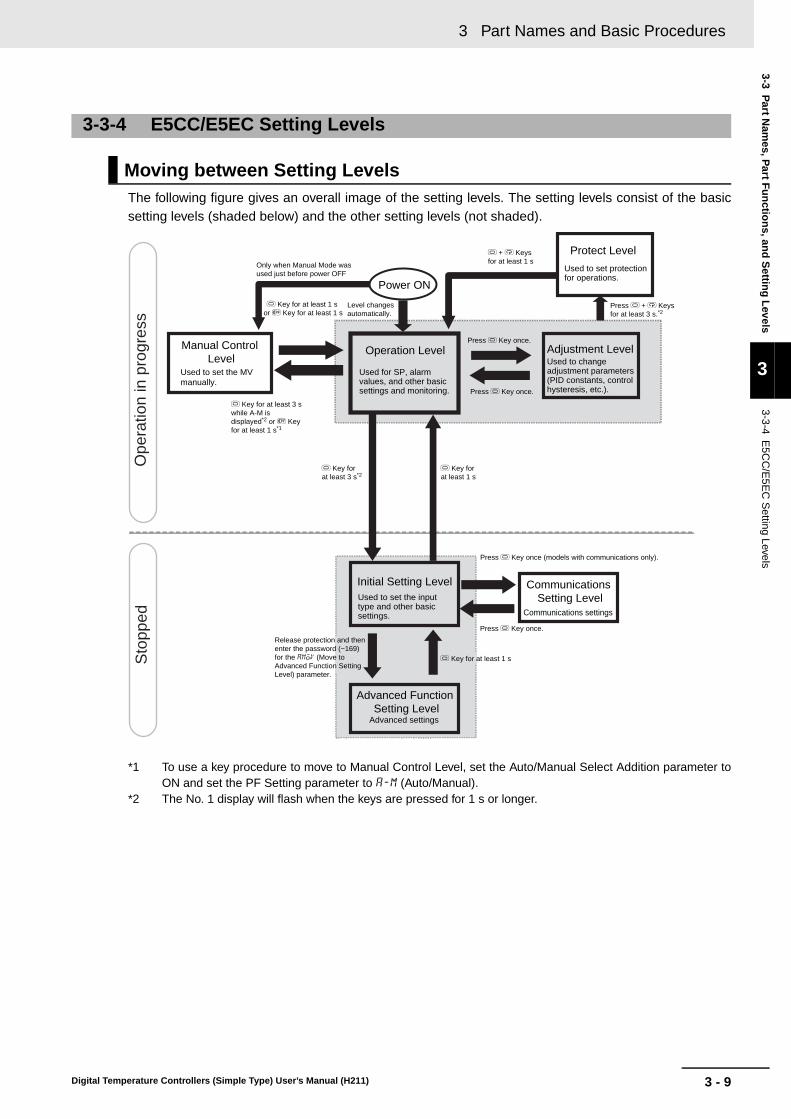
3 - 9
3 Part Names and Basic Procedures
Digital Temperature Controllers (Simple Type) User’s Manual (H211)
3-3 Part N
ames, P
art Fu
nctio
ns, an
d S
etting
Levels
3
3-3-4 E5C
C/E
5EC
Setting Levels
The following figure gives an overall image of the setting levels. The setting levels consist of the basicsetting levels (shaded below) and the other setting levels (not shaded).
*1 To use a key procedure to move to Manual Control Level, set the Auto/Manual Select Addition parameter toON and set the PF Setting parameter to a-m (Auto/Manual).
*2 The No. 1 display will flash when the keys are pressed for 1 s or longer.
3-3-4 E5CC/E5EC Setting Levels
Moving between Setting Levels
Advanced Function Setting Level
Power ON
Advanced settings
Initial Setting Level
Operation Level Adjustment Level
O Key for at least 1 s
Press O Key once.
O Key for at least 3 s*2
O Key for at least 1 s or S Key for at least 1 s
Protect Level
Manual Control Level
Press O Key once.
O Key for at least 1 s
Ope
ratio
n in
pro
gres
sS
topp
ed
Used for SP, alarm values, and other basic settings and monitoring.
Used to change adjustment parameters (PID constants, control hysteresis, etc.).
Used to set protection for operations.
Used to set the input type and other basic settings.
Used to set the MV manually.
Only when Manual Mode was used just before power OFF
O + M Keys for at least 1 s
Press O + M Keys for at least 3 s.*2
Level changes automatically.
O Key for at least 3 s while A-M is displayed*2 or S Key for at least 1 s*1
Release protection and then enter the password (−169) for the amoV (Move to Advanced Function Setting Level) parameter.
Press O Key once.
Press O Key once (models with communications only).
Communications Setting Level
Communications settings
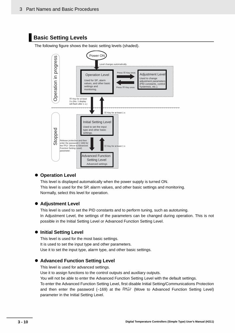
3 Part Names and Basic Procedures
3 - 10 Digital Temperature Controllers (Simple Type) User’s Manual (H211)
The following figure shows the basic setting levels (shaded).
Operation LevelThis level is displayed automatically when the power supply is turned ON.This level is used for the SP, alarm values, and other basic settings and monitoring.Normally, select this level for operation.
Adjustment LevelThis level is used to set the PID constants and to perform tuning, such as autotuning.In Adjustment Level, the settings of the parameters can be changed during operation. This is notpossible in the Initial Setting Level or Advanced Function Setting Level.
Initial Setting LevelThis level is used for the most basic settings.It is used to set the input type and other parameters.Use it to set the input type, alarm type, and other basic settings.
Advanced Function Setting LevelThis level is used for advanced settings.Use it to assign functions to the control outputs and auxiliary outputs.You will not be able to enter the Advanced Function Setting Level with the default settings.To enter the Advanced Function Setting Level, first disable Initial Setting/Communications Protectionand then enter the password (−169) at the amov (Move to Advanced Function Setting Level)parameter in the Initial Setting Level.
Basic Setting Levels
Advanced Function Setting Level
Power ON
Advanced settings
Initial Setting Level
Operation Level Adjustment Level
O Key for at least 1 s
Press O Key once.
Press O Key once.
Level changes automatically.
O Key for at least 1 s
Sto
pped
Used for SP, alarm values, and other basic settings and monitoring.
Used to change adjustment parameters (PID constants, control hysteresis, etc.).
O Key for at least 3 s (No. 1 display will flash after 1 s.)
Used to set the input type and other basic settings.
Release protection and then enter the password (−169) for the amoV (Move to Advanced Function Setting Level) parameter.
Ope
ratio
n in
pro
gres
s

3 - 11
3 Part Names and Basic Procedures
Digital Temperature Controllers (Simple Type) User’s Manual (H211)
3-3 Part N
ames, P
art Fu
nctio
ns, an
d S
etting
Levels
3
3-3-4 E5C
C/E
5EC
Setting Levels
Use the following procedure to move to Advanced Function Setting Level.
Step 1: Move to Protect Level.
Step 2: Display icpt (Initial Setting/Communications Protect) and set it to 0.
Step 3: Return to Operation Level.
Step 4: Return to Initial Setting Level.
Step 5: Display amoV (Move to Advanced Function Setting Level) and then enter −169.Steps 1 to 3 are necessary only the first time. Perform only steps 4 and 5 to move to AdvancedFunction Setting Level.
There are three other setting levels: Manual Control Level, Protect Level, and CommunicationsSetting Level.
Manual Control LevelThis level is used to set the MV manually. With the default settings, you cannot move to the ManualControl Level.• To use the S Key to move to the Manual Control Level, change the setting of the PF Setting
parameter to a-m.• To use the Level Key on the Auto/Manual Switch Display to move to the Manual Control Level, set
the Auto/Manual Switch Display Addition parameter in the Advanced Function Setting Level toON.
• To use an event input to move to the Manual Control Level, change the setting of the Event InputAssignment 1 to 4 parameter to manu.
Protect LevelThis level is used to restrict the operations that can be performed and the parameters that can bedisplayed with the front-panel keys. For example, you can prohibit changing the SP and otherparameters in the Operation Level and Adjustment Level. You can move to the Protect Level fromthe Operation Level or the Adjustment Level. To move to the Advanced Function Setting Level, youmust first cancel the protection that is set in the Protect Level.
Other Setting Levels
Advanced Function Setting Level
Power ON
Advanced settings
Step 5: Enter −169 for the amov parameter.
Move to Advanced Function Setting Level parameter
Enter −169. Default: 0
Operation LevelStep 4: O Key for at least 3 s
Step 3: Press the O + M Keys for at least 1 s.
Level changes automatically.
Initial Setting Level
Protect Level
0
icpt Initial Setting/Communications Protect
Set 0. Default: 1
Step 2: Change the parameter with the M Key and change the setting of the icpt parameter to 0.
amov0
a
Used for SP, alarm values, and other basic settings and monitoring.
Used to set the input type and other basic settings.
Used to set protection for operations.
Step 1: Press the O + M Keys simultaneously for at least 3 s.

3 Part Names and Basic Procedures
3 - 12 Digital Temperature Controllers (Simple Type) User’s Manual (H211)
Communications Setting LevelThis level is used to set the communications parameters. You can move to the Communications Set-ting Level from the Initial Setting Level.

3 - 13
3 Part Names and Basic Procedures
Digital Temperature Controllers (Simple Type) User’s Manual (H211)
3-4 Pro
cedu
res after Turn
ing
ON
the P
ow
er Su
pp
ly
3
3-4-1 Basic F
low of O
perations
3-4 Procedures after Turning ON the Power Supply
The basic flow of operations after you turn ON the power supply is shown below.
The basic procedure is given below.
1 Turn ON the power supply.
2 Set the input type.
3-4-1 Basic Flow of Operations
1. Turn ON the power supply.↓2. Set the input type.
↓3. Set the control method.
↓4. Set the alarm type.↓5. Set the set point.
↓6. Set the alarm set values.
3-4-2 Basic Procedure
25 0
s.err 0
Operation Level
s.err (input error) flashes on the display if a sensor is not connected or if the connected sensor is different from input type. Connect a sensor if one is not already connected.
25 0
in-t 5
in-t 0
in-t (IN-T): Indicates the Input Type parameter.
The default setting is 5 (5: K thermocouple at −200 to 1,300 °C).
Initial Setting Level
Initial Setting Level
The display flashes.
When you are finished, press the O (Level) Key for at least 1 second to return to the operation display.
Input Type: 0 (Pt100 resistance thermometer at −200 to 850 °C) (example)
Press the O (Level) Key for at least 3 seconds.
in-t (IN-T) will be displayed to show that the Initial Setting Level has been entered.
Press the U (Up) and D (Down) Keys to change the value.

3 Part Names and Basic Procedures
3 - 14 Digital Temperature Controllers (Simple Type) User’s Manual (H211)
* The default is 5.
List of Input Types
Input type Specifications Set value Temperature range in °C Temperature range in °FResistance thermometer
Pt100 0 −200 to 850 −300 to 1500
1 −199.9 to 500.0 −199.9 to 900.02 0.0 to 100.0 0.0 to 210.0
JPt100 3 −199.9 to 500.0 −199.9 to 900.0
4 0.0 to 100.0 0.0 to 210.0Thermocouple K 5* −200 to 1300 −300 to 2300
6 −20.0 to 500.0 0.0 to 900.0
J 7 −100 to 850 −100 to 15008 −20.0 to 400.0 0.0 to 750.0
T 9 −200 to 400 −300 to 700
10 −199.9 to 400.0 −199.9 to 700.0E 11 −200 to 600 −300 to 1100
L 12 −100 to 850 −100 to 1500
U 13 −200 to 400 −300 to 70014 −199.9 to 400.0 −199.9 to 700.0
N 15 −200 to 1300 −300 to 2300
R 16 0 to 1700 0 to 3000
S 17 0 to 1700 0 to 3000B 18 100 to 1800 300 to 3200
W 19 0 to 2300 0 to 3200
PLII 20 0 to 1300 0 to 2300Infrared temperature sensor ES1B
10 to 70°C 21 0 to 90 0 to 190
60 to 120°C 22 0 to 120 0 to 240
115 to 165°C 23 0 to 165 0 to 320140 to 260°C 24 0 to 260 0 to 500
Current input 4 to 20 mA 25 One of the following ranges according to the scaling:−1999 to 9999−199.9 to 999.9−19.99 to 99.99−1.999 to 9.999
0 to 20 mA 26Voltage input 1 to 5 V 27
0 to 5 V 28
0 to 10 V 29

3 - 15
3 Part Names and Basic Procedures
Digital Temperature Controllers (Simple Type) User’s Manual (H211)
3-4 Pro
cedu
res after Turn
ing
ON
the P
ow
er Su
pp
ly
3
3-4-2 Basic P
rocedure
3 Set the control method.
4 Set the alarm type.
* If the Controller is equipped with HB/HS alarm detection, the Alarm 1 Type is not displayed for the defaultsettings. To use alarm 1, set an output assignment to alarm 1.
If required, use the M (Mode) Key and the U (Up) and D (Down) Keys to repeat the procedure toset alarm types for alt2 (ALT2).
When you are finished, press the O (Level) Key for at least 1 second to return to the operation display.
cntl (CNTL): Indicates the control method.The default setting is onof (ONOF: ON/OFF control).
Initial Setting LevelInitial Setting LevelOperation LevelOperation Level
Initial Setting Level
Initial Setting Level
The display flashes.
ON/OFF Control
PID Controlcntl (CNTL): Indicates the control method.
Press the O (Level) Key for at least 3 seconds.
Press the M (Mode) Key several times to
display cntl (CNTL).
in-t (IN-T) will be displayed to show that the Initial Setting Level has been entered.
If pid (PID control) is displayed, press the D (Down) Key to change to onof (ONOF) (ON/OFF control).
If onof (ON/OFF control) is displayed, press the U (Up) Key to change to pid (PID) (PID control).
25 0
in-t 5
cntl onof
cntl pid
Initial Setting Level
Initial Setting Level
Press the M (Mode) Key several times to display alt1 (ALT1).
Press the U (Up) and D (Down) Keys to change
the value.
Alarm type: 7 (Lower-limit alarm with standby sequence) (example)
alt1 (ALT1): Indicates the Alarm 1 Type parameter.*The default setting is 2 (2: Upper-limit alarm).
25 0
in-t 5
alt1 2
alt1 7
Initial Setting LevelInitial Setting LevelOperation LevelOperation Level
The display flashes.Press the O (Level) Key for at least 3 seconds.
in-t (IN-T) will be displayed to show that the Initial Setting Level has been entered.

3 Part Names and Basic Procedures
3 - 16 Digital Temperature Controllers (Simple Type) User’s Manual (H211)
Alarm Type Numbers
Alarm type No.
Alarm type Description Operation
0 Alarm function OFF
There will be no alarm outputs. ---
1 Upper- and lower-limit alarm
The alarm output is ON while the PV is equal to or higher than the upper-limit alarm point or while the PV is equal to or lower than the lower-limit alarm point.
2 Upper-limit alarm
The alarm output is ON while the PV is equal to or higher than the upper-limit alarm point.
3 Lower-limit alarm
The alarm output is ON while the PV is equal to or lower than the lower-limit alarm point.
4 Upper- and lower-limit range alarm
The alarm output is ON while the PV is equal to or lower than the upper-limit alarm point or equal to or higher than the lower-limit alarm point.
5 Upper- and lower-limit alarm with standby sequence
This alarm provides a standby sequence.The alarm output is ON while the PV is equal to or higher than the upper-limit alarm point or while the PV is equal to or lower than the lower-limit alarm point.
6 Upper-limit alarm with standby sequence
This alarm provides a standby sequence.The alarm output is ON while the PV is equal to or higher than the upper-limit alarm point.
7 Lower-limit alarm with standby sequence
This alarm provides a standby sequence.The alarm output is ON while the PV is equal to or lower than the lower-limit alarm point.
Example:
OFF Temperature
Set point (e.g., 100°C)
ON
Lower-limit alarm point (e.g., 80°C)
Upper-limit alarm point (e.g., 130°C)
Alarm value upper limit (e.g., 30°C)
Alarm value lower limit (e.g., 20°C)
ON
Example:
OFF Temperature
Alarm value upper limit (e.g., 20°C)
Set point (e.g., 100°C)
Upper-limit alarm point (e.g., 120°C)
ON
Example:
OFF Temperature
Lower-limit alarm point (e.g., 80°C)
Set point (e.g., 100°C)
Alarm value lower limit (e.g., 20°C)
Example:
OFF Temperature
ON
Set point (e.g., 100°C)
Lower-limit alarm point (e.g., 80°C)
Alarm value lower limit (e.g., 20°C)
Upper-limit alarm point (e.g., 130°C)
Alarm value upper limit (e.g., 30°C)
Example:
OFF Temperature
ON
Lower-limit alarm point (e.g., 80°C)
Set point (e.g., 100°C)
Upper-limit alarm point (e.g., 130°C)
Alarm value upper limit (e.g., 30°C)
Alarm value lower limit (e.g., 20°C)
ON
Example:
OFF Temperature
Upper-limit alarm point (e.g., 120°C)
Alarm value upper limit (e.g., 20°C)
Set point (e.g., 100°C)
ON
OFF Temperature
Lower-limit alarm point (e.g., 80°C)
Set point (e.g., 100°C)
Alarm value lower limit (e.g., 20°C)
Example:

3 - 17
3 Part Names and Basic Procedures
Digital Temperature Controllers (Simple Type) User’s Manual (H211)
3-4 Pro
cedu
res after Turn
ing
ON
the P
ow
er Su
pp
ly
3
3-4-2 Basic P
rocedure
8 Absolute-value upper-limit alarm
The alarm output is ON while the PV is equal to or higher than the alarm value.
9 Absolute-value lower-limit alarm
The alarm output is ON while the PV is equal to or lower than the alarm value.
10 Absolute-value upper-limit alarm with standby sequence
This alarm provides a standby sequence.The alarm output is ON while the PV is equal to or higher than the alarm value.
11 Absolute-value lower-limit alarm with standby sequence
This alarm provides a standby sequence.The alarm output is ON while the PV is equal to or lower than the alarm value.
12 Loop Burnout Alarm (LBA) (Valid only for alarm 1.)
The alarm output turns ON when the control loop is broken.
There is assumed to be a loop burnout alarm if the control deviation (SP − PV) is greater than the threshold set in the LBA Level parameter and if the PV is not reduced by at least the value set in the LBA Band parameter within a specific period of time. The LBA detection time and LBA band are set in parameters.
Alarm type No.
Alarm type Description Operation
ON
OFF0
Temperature
Upper-limit alarm point (e.g., 100°C)
Alarm value (e.g., 100°C)
Example:
ON
OFF0
Temperature
Lower-limit alarm point (e.g., 100°C)
Example:
Alarm value (e.g., 100°C)
ON
OFF0
Temperature
Upper-limit alarm point (e.g., 100°C)
Alarm value (e.g., 100°C)
Example:
ON
OFF0
Temperature
Lower-limit alarm point (e.g., 100°C)
Example:
Alarm value (e.g., 100°C)
ON
SP
MV
LBA Alarm Output
PV
100%
0%
OFF Time
Time
Time
LBA detection time
LBA band
LBA level

3 Part Names and Basic Procedures
3 - 18 Digital Temperature Controllers (Simple Type) User’s Manual (H211)
13 PV change rate alarm
The alarm output turns ON if the change in the PV within the specified calculation period exceeds a specific width.
The PV rate of change calculation period and the alarm value are set in parameters.
14 SP absolute-value upper-limit alarm
The alarm output is ON while the SP is equal to or higher than the alarm value.
15 SP absolute-value lower-limit alarm
The alarm output is ON while the SP is equal to or lower than the alarm value.
16 MV absolute-value upper-limit alarm
The alarm output is ON while the MV is equal to or higher than the alarm value.
17 MV absolute-value lower-limit alarm
The alarm output is ON while the MV is equal to or lower than the alarm value.
Alarm type No.
Alarm type Description Operation
PV
PV Change Rate Alarm Output
PV rate of change calculation period
Change rate width
ON
OFF Time
Time
ON
OFF0
SP
Upper-limit alarm point (e.g., 100°C)
Alarm value (e.g., 100°C)
Example:
ON
OFF0
SP
Lower-limit alarm point (e.g., 100°C)
Example:
Alarm value (e.g., 100°C)
ON
OFF0
MV
Upper-limit alarm point (e.g., 60%)
Alarm value (e.g., 60%)
Example for Standard Control:
ON
OFF0
MV
Lower-limit alarm point (e.g., 80%)
Example for Standard Control:
Alarm value (e.g., 80%)

3 - 19
3 Part Names and Basic Procedures
Digital Temperature Controllers (Simple Type) User’s Manual (H211)
3-4 Pro
cedu
res after Turn
ing
ON
the P
ow
er Su
pp
ly
3
3-4-2 Basic P
rocedure
5 Set the set point.
6 Set the alarm set value or values.
This concludes the procedure to set the input type, alarm type, control method, set point, and alarmset values.
*Hold the U (Up) or D (Down) Key to increment or decrement the value quickly.
Operation Display
Set point: 500°C (example)
Press the U (Up) and D (Down) Keys and the S (Shift) Key to change the value.
25 0
25 500
al-1 0
al1h 0
al1l 0
Change the parameter that is displayed with the M (Mode) Key.
Operation Level
Press the M (Mode) Key several times to display al-1 (AL-1).
Alarm Type 2, 3, 6, 7, 8, 9,10, or 11 (Upper-limit Alarms and Lower-limit Alarms)
Alarm Type 1, 4, or 5 (Upper-limit and Lower-limit Alarms or Upper-limit and Lower-limit Range Alarms)
To set the alarm value upper limit, press the M (Mode) Key several times to display al1h (AL1H).
To set the alarm value lower limit, press the M (Mode) Key several times to display al1l (AL1L).
3 Part Names and Basic Procedures
3 - 20 Digital Temperature Controllers (Simple Type) User’s Manual (H211)

A - 1Digital Temperature Controllers (Simple Type) User’s Manual (H211)
A
A-1 Specifications . . . . . . . . . . . . . . . . . . . . . . . . . . . . . . . . . . . . . . . . . . . . . . . . . A-2A-1-1 Ratings . . . . . . . . . . . . . . . . . . . . . . . . . . . . . . . . . . . . . . . . . . . . . . . . . . . . . . . A-2A-1-2 Characteristics . . . . . . . . . . . . . . . . . . . . . . . . . . . . . . . . . . . . . . . . . . . . . . . . . A-3A-1-4 Waterproof Packing . . . . . . . . . . . . . . . . . . . . . . . . . . . . . . . . . . . . . . . . . . . . . . A-4
A-3 Error Displays . . . . . . . . . . . . . . . . . . . . . . . . . . . . . . . . . . . . . . . . . . . . . . . . . A-6
A-4 Troubleshooting . . . . . . . . . . . . . . . . . . . . . . . . . . . . . . . . . . . . . . . . . . . . . . . A-9
A-5 Parameter Operation Lists . . . . . . . . . . . . . . . . . . . . . . . . . . . . . . . . . . . . . A-12A-5-1 Operation Level . . . . . . . . . . . . . . . . . . . . . . . . . . . . . . . . . . . . . . . . . . . . . . . . A-12A-5-2 Adjustment Level . . . . . . . . . . . . . . . . . . . . . . . . . . . . . . . . . . . . . . . . . . . . . . A-13A-5-3 Initial Setting Level . . . . . . . . . . . . . . . . . . . . . . . . . . . . . . . . . . . . . . . . . . . . . A-14A-5-4 Manual Control Level . . . . . . . . . . . . . . . . . . . . . . . . . . . . . . . . . . . . . . . . . . . A-17A-5-5 Advanced Function Setting Level . . . . . . . . . . . . . . . . . . . . . . . . . . . . . . . . . . A-17A-5-6 Protect Level . . . . . . . . . . . . . . . . . . . . . . . . . . . . . . . . . . . . . . . . . . . . . . . . . . A-19
A-6 Sensor Input Setting Range, Indication Range, Control Range . . . . . . . A-21
A-7 Setting Levels Diagram . . . . . . . . . . . . . . . . . . . . . . . . . . . . . . . . . . . . . . . . A-22
A-8 Parameter Flow . . . . . . . . . . . . . . . . . . . . . . . . . . . . . . . . . . . . . . . . . . . . . . . A-24
Appendices

A Appendices
A - 2 Digital Temperature Controllers (Simple Type) User’s Manual (H211)
A-1 Specifications
*1 For input setting ranges, refer to A-6 Sensor Input Setting Range, Indication Range, Control Range.*2 When connecting the ES2-HB/THB, connect it 1:1.
HB and HS Alarms(E5CC/E5EC Models with HB and HS Alarms)
*1 HB alarms are not detected and the heater power is not measured if the ON time for the control output forheating is 100 ms or less (30 ms or less if the control period is 0.1 or 0.2 s).
*2 HS alarms are not detected and the leakage power is not measured if the ON time for the control outputfor heating is 100 ms or less (35 ms or less if the control period is 0.1 or 0.2 s).
A-1-1 Ratings
Supply voltage 100 to 240 VAC, 50/60 Hz 24 VAC, 50/60 Hz/24 VDC
Operating voltage range 85% to 110% of rated supply voltage
Power consumption
E5CCOption number 800: 5.2 VA max.Other option numbers: 6.5 VA max.
Option number 800: 3.1 VA max./1.6 W max.Other option numbers: 4.1 VA max./2.3 W max.
E5ECOption number 800: 6.6 VA max.Other option numbers: 8.3 VA max.
Option number 800: 4.1 VA max./2.3 W max.Other option numbers: 5.5 VA max./3.2 W max.
Sensor input *1
Thermocouple: K, J, T, E, L, U, N, R, S, B, W, PLIIPlatinum resistance thermometer: Pt100, JPt100Infrared temperature sensor: 10 to 70°C, 60 to 120°C, 115 to 165°C, 140 to 260°CCurrent input *2: 4 to 20 mA, 0 to 20 mA (Input impedance: 150 Ω max.)
Voltage input *2: 1 to 5 V, 0 to 5 V, 0 to 10 V (Input impedance: 1 MΩ min.)
Control output 1/2
Relay output
E5CCSPST-NO, 250 VAC, 3 A (resistive load), electrical durability: 100,000 operations
Min. applicable load: 5 V, 10 mA
E5ECSPST-NO, 250 VAC, 5 A (resistive load), electrical durability: 100,000 operationsMin. applicable load: 5 V, 10 mA
Voltage output
E5CCOutput voltage 12 VDC ±20% (PNP), max. load current 21 mA, with short-circuit protection circuit
E5ECOutput voltage 12 VDC ±20% (PNP), max. load current 40 mA, with short-circuit protection circuit (21 mA if there are two control outputs)
Current output4 to 20 mA DC, 0 to 20 mA DC, Load: 500 Ω max.
Resolution: Approx. 10,000
Auxiliary output Relay outputsSPST-NO, 250 VAC, 3 A (resistive load), electrical durability: 100,000 operationsMin. applicable load: 5 V, 10 mA
Control method 2-PID or ON/OFF control
Setting method Digital setting using front panel keys
Indication method 11-segment digital displays and individual indicators
Other functions Depend on the model
Ambient temperature −10 to 55°C (with no condensation or icing); with 3-year guarantee: −10 to 50°CAmbient humidity 25% to 85%
Storage temperature −25 to 65°C (with no condensation or icing)
Altitude 2,000 m max.
Recommended fuse T2A, 250 VAC, time lag, low shut-off capacity
Installation environment Installation Category II, Pollution Class 2 (IEC 61010-1 compliant)
Max. heater current 50 A AC
Input current readout accuracy ±5% FS ±1 digit max.
Heater burnout alarm setting range
0.1 to 49.9 A (0.1 A units)0.0 A: Heater burnout alarm output turns OFF.50.0 A: Heater burnout alarm output turns ON.Min. detection ON time *1: 30 ms for a control period of 0.1 s or 0.2 s
100 ms for a control period of 0.5 s or 1 to 99 s
Heater short alarm setting range
0.1 to 49.9 A (0.1 A units)0.0 A: Heater short alarm output turns ON.50.0 A: Heater short alarm output turns OFF.Min. detection OFF time *2: 35 ms for a control period of 0.1 s or 0.2 s
100 ms for a control period of 0.5 s or 1 to 99 s

A - 3
A Appendices
Digital Temperature Controllers (Simple Type) User’s Manual (H211)
A-1 S
pecificatio
ns
A
A-1-2 C
haracteristics
*1 The indication accuracy of K, T, and N thermocouples at a temperature of −100°C or less is ±2°C ±1 digit maximum.The indication accuracy of U and L thermocouples is ±2°C ±1 digit maximum.The indication accuracy of B thermocouples at a temperature of 400°C or less is not specified.The indication accuracy of B thermocouples at a temperature of 400 to 800°C is ±3°C maximum.The indication accuracy of R and S thermocouples at a temperature of 200°C or less is ±3°C ±1 digit maximum.The indication accuracy of W thermocouples is (±0.3% of PV or ±3°C, whichever is greater) ±1 digit maximum.The indication accuracy of PLII thermocouples is (±0.3% of PV or ±2°C, whichever is greater) ±1 digit maximum.
*2 Ambient temperature: −10°C to 23°C to 55°CVoltage range: −15 to +10% of rated voltage
*3 The unit is determined by the setting of the Integral/Derivative Time Unit parameter.
A-1-2 Characteristics
Indication accuracy(ambient temperature of 23°C)
Thermocouple *1 (±0.3% of PV or ±1°C, whichever is greater) ±1 digit max.
Resistance thermometer
(±0.2% of PV or ±0.8°C, whichever is greater) ±1 digit max.
Analog input ±0.2% FS ±1 digit max.
CT input ±5% FS ±1 digit max.
Temperature variation
influence *2
Voltage variation influence *2
Thermocouple
Thermocouple (R, S, B, W, PLII)(±1% of PV or ±10°C, whichever is greater) ±1 digit max.Other thermocouples:(±1% of PV or ±4°C, whichever is greater) ±1 digit max. *K thermocouple at −100°C max: ±10°C max.
Resistance thermometer
(±1% of PV or ±2°C, whichever is greater) ±1 digit max.
Analog input ±1% FS ±1 digit max.CT input ±5% FS ±1 digit max.
HysteresisTemperature input 0.1 to 999.9°C or °F (in units of 0.1°C or °F)
Analog input 0.01% to 99.99% FS (in units of 0.01% FS)
Proportional band (P)Temperature input 0.1 to 999.9°C or °F (in units of 0.1°C or °F)
Analog input 0.1% to 999.9% FS (in units of 0.1% FS)
Integral time (I) *30 to 9,999 s (in units of 1 s)0.0 to 999.9 s (in units of 0.1 s)
Derivative time (D) *30 to 9,999 s (in units of 1 s)0.0 to 999.9 s (in units of 0.1 s)
Control Period 0.1, 0.2, 0.5, or 1 to 99 s (in units of 1 s)
Manual reset value 0.0% to 100.0% (in units of 0.1%)Alarm setting range −1,999 to 9,999 (decimal point position depends on input type)
Sampling cycle 50 ms
Insulation resistance 20 MΩ min. (at 500 VDC)
Dielectric strength 2,300 VAC, 50/60 Hz for 1 min between terminals of different charge
Malfunction vibration 10 to 55 Hz, 20 m/s2 for 10 min each in X, Y and Z directions
Vibration resistance 10 to 55 Hz, 20 m/s2 for 2 hr each in X, Y, and Z directions
Malfunction shock 100 m/s2, 3 times each in X, Y, and Z directions
Shock resistance 300 m/s2, 3 times each in X, Y, and Z directions
WeightE5CC
Approx. 120 g Adapter: Approx. 10 g
Terminal cover: Approx. 0.5 g each
E5ECApprox. 210 g Adapter:
Approx. 4 g × 2Terminal Cover: Approx. 1 g each
Degree of protection Front panel: IP66, rear case: IP20, terminals: IP00
Memory protection Non-volatile memory (number of writes: 1,000,000)
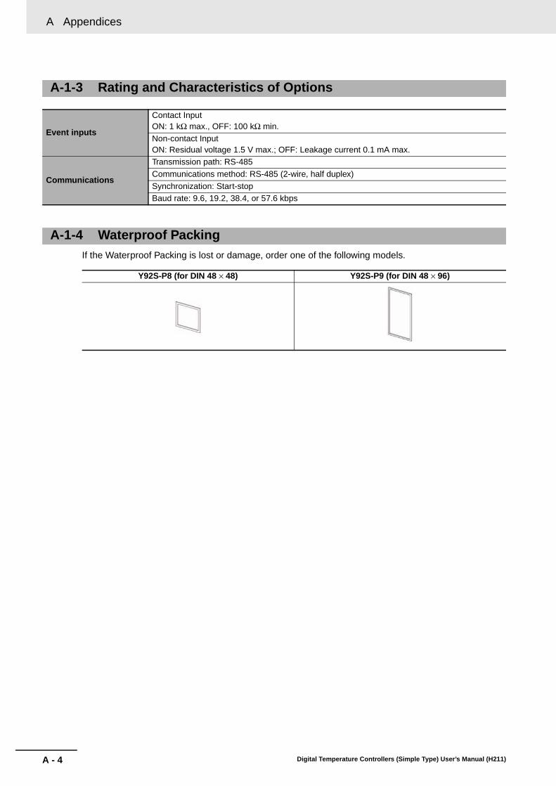
A Appendices
A - 4 Digital Temperature Controllers (Simple Type) User’s Manual (H211)
If the Waterproof Packing is lost or damage, order one of the following models.
A-1-3 Rating and Characteristics of Options
Event inputs
Contact InputON: 1 kΩ max., OFF: 100 kΩ min.
Non-contact InputON: Residual voltage 1.5 V max.; OFF: Leakage current 0.1 mA max.
Communications
Transmission path: RS-485
Communications method: RS-485 (2-wire, half duplex)
Synchronization: Start-stopBaud rate: 9.6, 19.2, 38.4, or 57.6 kbps
A-1-4 Waterproof Packing
Y92S-P8 (for DIN 48 × 48) Y92S-P9 (for DIN 48 × 96)

A - 5
A Appendices
Digital Temperature Controllers (Simple Type) User’s Manual (H211)
A-2 C
urren
t Transfo
rmer (C
T)
A
A-2 Current Transformer (CT)
*1 The maximum continuous current of the E5CC/E5EC is 50 A.
• E54-CT1
• E54-CT3
A-2-1 Specifications
Item SpecificationsModel number E54-CT1 E54-CT3
Max. continuous current 50 A 120 A *1
Dielectric strength 1,000 VAC (for 1 min)
Vibration resistance 50 Hz, 98 m/s2
Weight Approx. 11.5 g Approx. 50 g
Accessories None Armature (2), Plug (2)
A-2-2 Dimensions (Unit: mm)
2115
25
3
10
30
40
2.8
5.8 dia.
Two, 3.8 dia.
10.5
7.5
30
40
15
9
12 dia.
Two, M3 holes, depth: 4
2.36 dia.
40
30

A Appendices
A - 6 Digital Temperature Controllers (Simple Type) User’s Manual (H211)
A-3 Error Displays
When an error occurs, the error contents are shown on the No. 1 or the No. 2 display.This section describes how to check error codes on the display, and the actions to be taken to remedythe problems.
MeaningThe input value has exceeded the control range. *The input type setting is not correct. The sensor is disconnected or shorted. The sensor wiring is not correct. The sensor is not wired.
* Control Range
ActionCheck the wiring of inputs for miswiring, disconnections, and short-circuits and check the input type.If no abnormality is found in the wiring and input type, turn the power OFF then back ON again.If the display remains the same, the Controller must be replaced. If the display is restored, then theprobable cause is electrical noise affecting the control system. Check for electrical noise.Note: With resistance thermometer input, a break in the A, B, or B' line is regarded as a disconnection.
OperationAfter an error occurs, the error is displayed and the alarm outputs function as if the upper limit hasbeen exceeded.If an input error is assigned to a control output or auxiliary output, the output will turn ON when theinput error occurs. The error message will appear in the display for the PV.Note: The heating and cooling control outputs will turn OFF. When the manual MV is set, the control output is
determined by the set value.
s.err Input Error
Resistance thermometer, thermocouple input:
Temperature setting lower limit −20°C to temperature setting upper limit +20°C(Temperature setting lower limit −40°F to temperature setting upper limit +40°F)
ES1B input: Same as input indication range
Analog input: −5% to +105% of scaling range
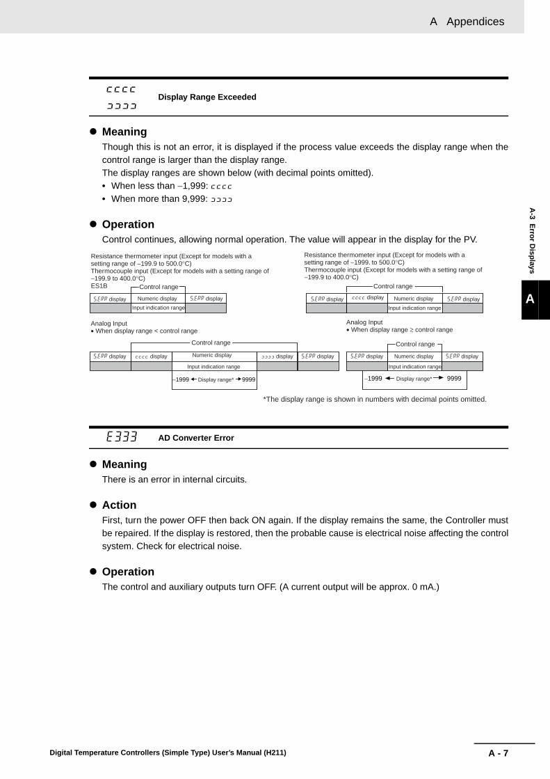
A - 7
A Appendices
Digital Temperature Controllers (Simple Type) User’s Manual (H211)
A-3 E
rror D
isplays
A
MeaningThough this is not an error, it is displayed if the process value exceeds the display range when thecontrol range is larger than the display range.The display ranges are shown below (with decimal points omitted).• When less than −1,999: [[[[• When more than 9,999: ]]]]
OperationControl continues, allowing normal operation. The value will appear in the display for the PV.
MeaningThere is an error in internal circuits.
ActionFirst, turn the power OFF then back ON again. If the display remains the same, the Controller mustbe repaired. If the display is restored, then the probable cause is electrical noise affecting the controlsystem. Check for electrical noise.
OperationThe control and auxiliary outputs turn OFF. (A current output will be approx. 0 mA.)
[[[[
]]]]Display Range Exceeded
e333 AD Converter Error
−1999 9999 −1999 9999
Resistance thermometer input (Except for models with a setting range of −199.9 to 500.0°C)Thermocouple input (Except for models with a setting range of −199.9 to 400.0°C)ES1B Control range
s.err display Numeric display s.err display
Input indication range
Analog Input• When display range < control range
Control range
s.err display [[[[ display Numeric display
Input indication range
]]]] display s.err display
Resistance thermometer input (Except for models with a setting range of −1999. to 500.0°C)Thermocouple input (Except for models with a setting range of −199.9 to 400.0°C)
Control range
s.err display [[[[ display Numeric display
Input indication range
s.err display
Analog Input• When display range ≥ control range
Control range
s.err display Numeric display s.err display
Display range*
*The display range is shown in numbers with decimal points omitted.
Input indication range
Display range*

A Appendices
A - 8 Digital Temperature Controllers (Simple Type) User’s Manual (H211)
MeaningInternal memory operation is in error.
ActionFirst, turn the power OFF then back ON again. If the display remains the same, the Controller mustbe repaired. If the display is restored, then the probable cause is electrical noise affecting the controlsystem. Check for electrical noise.
OperationThe control and auxiliary outputs turn OFF. (A current output will be approx. 0 mA.)
MeaningThis error is displayed when the heater current value exceeds 55.0 A.
OperationControl continues, allowing normal operation. An error message is displayed when the followingitems are displayed.Heater current 1 value monitorLeakage current 1 monitor
MeaningIf there is an HB or HS alarm, the relevant parameter will flash on the No. 1 display.
OperationThe relevant Heater Current 1 Value Monitor or Leakage Current 1 Monitor in the Operation orAdjustment Level will flash on the No. 1 display. However, control continues and operation is normal.
e111 Memory Error
ffff Current Value Exceeds
ct1
lcr1
HB AlarmHS Alarm

A - 9
A Appendices
Digital Temperature Controllers (Simple Type) User’s Manual (H211)
A-4 Tro
ub
lesho
otin
g
A
A-4 Troubleshooting
Checking ProblemsIf the Digital Controller is not operating normally, check the following points before requesting repairs. Ifthe problem persists, contact your OMRON representative for details on returning the product.
* Refer to the E5CC/E5EC Digital Temperature Controllers Communications Manual (Cat. No. H175) for details.
Timing Status Meaning Countermeasures
Turning ON the power for the first time
The TUNE indicator will flash.
ST (self-tuning) is in progress (default setting: ON).
This is not a product fault.The TUNE indicator flashes during self-tuning.
Temperature error is large.Input error (S.Err display)
Input type mismatch Check the sensor type and reset the input type correctly.
Thermometer is not installed properly.
Check the thermometer installation location and polarity and install correctly.
Communications are not possible.*
Non-recommended adapter is being used.
Make sure that the connected device is not faulty.
During operation
OvershootingUndershootingHunting
ON/OFF control is enabled (default: ON/OFF control selected).
Select PID control and execute either ST (self-tuning) or AT (auto-tuning). When using self-tuning, turn ON the power supply to the Digital Controller and load (heater, etc.) at the same time, or turn ON the load power supply first. Accurate self-tuning and optimum control will not be possible if the power supply to the load is turned ON after turning ON the power supply to the Digital Controller.
Control period is longer compared with the speed of rise and fall in temperature.
Shorten the control period. A shorter control period improves control performance, but a cycle of 20 ms minimum is recommended in consideration of the service life of the relays.
Unsuitable PID constant Set appropriate PID constants using either of the following methods.• Execute AT (autotuning).• Set PID constants individually using manual settings.
SSR operation fault Use bleeder resistance if the problem is due to leakage current. Also investigate the errors detected by the HS alarm function.
Temperature is not rising Specified operation is unsuitable for required control (default: Reverse operation).
Select either forward or reverse operation depending on the required control. Reverse operation is used for heating operations.
Heater is burnt out or deteriorated.
Check whether heater burnout or deterioration have occurred. Also investigate the errors detected by the heater burnout alarm.
Insufficient heater capacity Check whether the heater's heating capacity is sufficient.
Cooling system in operation. Check whether a cooling system is operating.
Peripheral devices have heat prevention device operating.
Set the heating prevention temperature setting to a value higher than the set temperature of the Digital Controller.

A Appendices
A - 10 Digital Temperature Controllers (Simple Type) User’s Manual (H211)
Timing Status Meaning Countermeasures
During operation (continued)
Output will not turn ON Set to STOP (default: RUN) Set the RUN/STOP mode to RUN. If STOP is lit on the display, control is stopped.
Specified operation is unsuitable for required control (default: Reverse operation).
Select either forward or reverse operation depending on the required control. Reverse operation is used for heating operations.
A high hysteresis is set for ON/OFF operation (default: 1.0°C)
Set a suitable value for the hysteresis.
Temperature Controller will not operate
Set to STOP (default: RUN) Set the RUN/STOP mode to RUN. If STOP is lit on the display, control is stopped.
Temperature error is largeInput error (S.err display)
Thermometer has burnt out or short-circuited.
Check whether the thermometer has burnt out or short-circuited.
Thermometer lead wires and power lines are in the same conduit, causing noise from the power lines (generally, display values will be unstable).
Wire the lead wires and power lines in separate conduits, or wire them using a more direct path.
Connection between the Digital Controller and thermocouple is using copper wires.
Connect the thermocouple's lead wires directly, or connect a compensating conductor suitable for the thermocouple.
Installation location of thermometer is unsuitable.
Make sure that the location that is being measured with the temperature sensor is suitable.
Input shift is not set correctly (default: 0°C)
Set a suitable input shift. If input shift is not required, set the input shift value to 0.0.
Keys will not operate Setting change protect is ON. Turn OFF setting change protect.
Cannot shift levels Operations limited due to protection.
Set the operation/adjustment protect, initial setting/communications protect, and setting change protect values as required.
After long service life
Control is unstable Terminal screws may be loose.
Retighten terminal screws to a torque of 0.43 to 0.58 N·m.
The internal components have reached the end of their service life.
The Digital Controller's internal electrolytic capacitor depends on the ambient temperature, and load rate. The structural life depends on the ambient environment (shock, vibration). The life expectancy of the output relays varies greatly with the switching capacity and other switching conditions. Always use the output relays within their rated load and electrical life expectancy. If an output relay is used beyond its life expectancy, its contacts may become welded or burned. Replace the Digital Controller and all other Digital Controllers purchased in the same time period.

A - 11
A Appendices
Digital Temperature Controllers (Simple Type) User’s Manual (H211)
A-4 Tro
ub
lesho
otin
g
A
A-2-2 D
imensions (U
nit: mm
)
Symptom: Cannot Communicate or a Communications Error Occurs
* Refer to the E5CC/E5EC Digital Temperature Controllers Communications Manual (Cat. No. H175) fordetails.
Meaning Countermeasures
The communications wiring is not correct. Correct the wiring.
The communications line has become disconnected.
Connect the communications line securely and tighten the screws.
The communications cable is broken. Replace the cable.
The communications cable is too long. The total cable length for RS-485 is 500 m max.
The wrong communications cable has been used.
Use a shielded, AWG24 to AWG18 (cross-sectional area of 0.205 to 0.823
mm2) twisted-pair cable for the communications cable.
More than the specified number of communications devices are connected to the same communications path.
When 1:N communications are used, a maximum of 32 nodes may be connected, including the host node.
An end node has not been set at each end of the communications line.
Set or connect terminating resistance at each end of the line. If the E5CC/E5EC is the end node, 120-Ω (1/2-W) terminating resistance is used. Be sure that the combined resistance with the host device is 54 Ω minimum.
The specified power supply voltage is not being supplied to the Controller.
Supply the specified power supply voltage.
The specified power supply voltage is not being supplied to an Interface Converter (such as the K3SC).
Supply the specified power supply voltage.
The same baud rate and communications method are not being used by all of the Controllers, host devices, and other devices on the same communications line.
Set the same values for the baud rate, protocol, data length, stop bits, and parity on all nodes.
The unit number specified in the command frame is different from the unit number set by the Controller.
Use the same unit number.
The same unit number as the Controller is being used for another node on the same communications line.
Set each unit number for only one node.
There is a mistake in programming the host device.
Use a line monitor to check the commands. Check operation using a sample program.
The host device is detecting the absence of a response as an error before it receives the response from the Controller.
Shorten the send data wait time in the Controller or increase the response wait time in the host device.
The host device is detecting the absence of a response as an error after broadcasting a command.
The Controller does not return responses for broadcast commands.
The host device sent another command before receiving a response from the Controller.
The response must always be read after sending a command (except for broadcast commands).
The host device sent the next command too soon after receiving a response from the Controller.
After receiving a response, wait at least 2 ms before sending the next command.
The communications line became unstable when Controller power was turned ON or interrupted, and the host device read the unstable status as data.
Initialize the reception buffer in the host device before sending the first command and after turning OFF the power to the Controller.
The communications data was corrupted from noise from the environment.
Try using a slower baud rate.Separate the communications cable from the source of noise.Use a shielded, twisted-pair cable for the communications cable.Use as short a communications cable as possible, and do not lay or loop extra cable.To prevent inductive noise, do not run the communications cable parallel to a power line.If noise countermeasures are difficult to implement, use an Optical Interface.

A Appendices
A - 12 Digital Temperature Controllers (Simple Type) User’s Manual (H211)
A-5 Parameter Operation Lists
A-5-1 Operation Level
Parameters Characters Setting (monitor) value Display Default Unit
Process Value Temperature: According to indication range for each sensor.Analog: Scaling lower limit −5% FS to Scaling upper limit +5% FS
EU
Set Point SP lower limit to SP upper limit 0 EU
Multi-SP Set Point Selection
m-sp 0 to 7 0 None
Set Point During SP Ramp
sp-m SP lower limit to SP upper limit EU
Heater Current 1 Value Monitor
ct1 0.0 to 55.0 A
Leakage Current 1 Monitor
lcr1 0.0 to 55.0 A
RUN/STOP r-s RUN/STOP run, stop Run None
Alarm Value 1 al-1 All alarms except for MV absolute-value upper-limit or lower-limit alarms: −1,999 to 9,999
0 EU
MV absolute-value upper-limit or lower-limit alarms: −199.9 to 999.9
0.0 %
Alarm Value Upper Limit 1 al1h −1,999 to 9,999 0 EU
Alarm Value Lower Limit 1 al1l −1,999 to 9,999 0 EU
Alarm Value 2 al-2 All alarms except for MV absolute-value upper-limit or lower-limit alarms: −1,999 to 9,999
0 EU
MV absolute-value upper-limit or lower-limit alarms: −199.9 to 999.9
0.0 %
Alarm Value Upper Limit 2 al2h −1,999 to 9,999 0 EU
Alarm Value Lower Limit 2 al2l −1,999 to 9,999 0 EU
Alarm Value 3 al-3 All alarms except for MV absolute-value upper-limit or lower-limit alarms: −1,999 to 9,999
0 EU
MV absolute-value upper-limit or lower-limit alarms: −199.9 to 999.9
0.0 %
Alarm Value Upper Limit 3 al3h −1,999 to 9,999 0 EU
Alarm Value Lower Limit 3 al3l −1,999 to 9,999 0 EU
Alarm Value 4 al-4 All alarms except for MV absolute-value upper-limit or lower-limit alarms: −1,999 to 9,999
0 EU
MV absolute-value upper-limit or lower-limit alarms: −199.9 to 999.9
0.0 %
Alarm Value Upper Limit 4 al4h −1,999 to 9,999 0 EU
Alarm Value Lower Limit 4 al4l −1,999 to 9,999 0 EU
MV Monitor (Heating) o −5.0 to 105.5 (standard)0.0 to 105.0 (heating/cooling)
%
MV Monitor (Cooling) c-o 0.0 to 105.0 %

A - 13
A Appendices
Digital Temperature Controllers (Simple Type) User’s Manual (H211)
A-5 P
arameter O
peratio
n L
ists
A
A-5-2 A
djustment Level
A-5-2 Adjustment Level
Parameters Characters Setting (monitor) value Display Default Unit
AT Execute/Cancel at OFF, AT CancelAT-2: 100%AT ExecuteAT-1: 40%AT Execute
off, at-2, at-1
OFF None
Communications Writing
cmwt OFF, ON off, on OFF None
Heater Current 1 Value Monitor
ct1 0.0 to 55.0 A
Heater Burnout Detection 1
hb1 0.0 to 50.0 0.0 A
Leakage Current 1 Monitor
lcr1 0.0 to 55.0 A
HS Alarm 1 hs1 0.0 to 50.0 50.0 A
SP 0 sp-0 SP lower limit to SP upper limit 0 EU
SP 1 sp-1 SP lower limit to SP upper limit 0 EU
SP 2 sp-2 SP lower limit to SP upper limit 0 EU
SP 3 sp-3 SP lower limit to SP upper limit 0 EU
SP 4 sp-4 SP lower limit to SP upper limit 0 EU
SP 5 sp-5 SP lower limit to SP upper limit 0 EU
SP 6 sp-6 SP lower limit to SP upper limit 0 EU
SP 7 sp-7 SP lower limit to SP upper limit 0 EU
Process Value Input Shift
ins Temperature input: −199.9 to 999.9 0.0 °C or °FAnalog input: −1,999 to 9,999 0 EU
Proportional Band p Temperature input: 0.1 to 999.9 8.0 °C or °FAnalog input: 0.1 to 999.9 10.0 %FS
Integral Time i Integral/Derivative Time Unit of 1 s: 0 to 9,999Integral/Derivative Time Unit of 0.1 s: 0.0 to 999.9
233233.0
Seconds
Derivative Time d Integral/Derivative Time Unit of 1 s: 0 to 9,999Integral/Derivative Time Unit of 0.1 s: 0.0 to 999.9
4040.0
Seconds
Proportional Band (Cooling)
c-p Temperature input: 0.1 to 999.9 8.0 °C or °FAnalog input: 0.1 to 999.9 10.0 %FS
Integral Time (Cooling) c-i Integral/Derivative Time Unit of 1 s: 0 to 9,999Integral/Derivative Time Unit of 0.1 s: 0.0 to 999.9
233233.0
Seconds
Derivative Time (Cooling)
c-d Integral/Derivative Time Unit of 1 s: 0 to 9,999Integral/Derivative Time Unit of 0.1 s: 0.0 to 999.9
4040.0
Seconds
Dead Band c-db Temperature input: −199.9 to 999.9 0.0 °C or °FAnalog input: −19.99 to 99.99 0.00 %FS
Manual Reset Value of-r 0.0 to 100.0 50.0 %
Hysteresis (Heating) hys Temperature input: 0.1 to 999.9 1.0 °C or °FAnalog input: 0.01 to 99.99 0.10 %FS
Hysteresis (Cooling) chys Temperature input: 0.1 to 999.9 1.0 °C or °FAnalog input: 0.01 to 99.99 0.10 %FS
SP Ramp Set Value sprt OFF, 1 to 9,999 off, 1 to 9999
OFF EU/s, EU/min, EU/h
MV Upper Limit ol-h MV lower limit +0.1 to 105.0 (standard)0.0 to 105.0 (heating/cooling)
100.0 %
MV Lower Limit ol-l −5.0 to MV upper limit −0.1 (standard)−105.0 to 0.0 (heating/cooling)
0.0 (standard)−100.0 (heating/cooling)
%
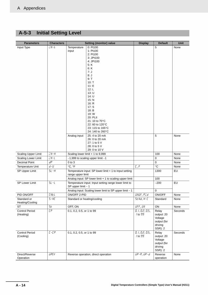
A Appendices
A - 14 Digital Temperature Controllers (Simple Type) User’s Manual (H211)
A-5-3 Initial Setting Level
Parameters Characters Setting (monitor) value Display Default Unit
Input Type in-t Temperature input
0: Pt1001: Pt1002: Pt1003: JPt1004: JPt1005: K6: K7: J8: J9: T10: T11: E12: L13: U14: U15: N16: R17: S18: B19: W20: PLII21: 10 to 70°C22: 60 to 120°C23: 115 to 165°C24: 140 to 260°C
5 None
Analog input 25: 4 to 20 mA26: 0 to 20 mA27: 1 to 5 V28: 0 to 5 V29: 0 to 10 V
5 None
Scaling Upper Limit in-h Scaling lower limit + 1 to 9,999 100 None
Scaling Lower Limit in-l −1,999 to scaling upper limit −1 0 None
Decimal Point dp 0 to 3 0 None
Temperature Unit d-u °C, °F c, f °C None
SP Upper Limit sl-h Temperature input: SP lower limit + 1 to Input setting range upper limit
1300 EU
Analog input: SP lower limit + 1 to scaling upper limit 100
SP Lower Limit sl-l Temperature input: Input setting range lower limit to SP upper limit − 1
−200 EU
Analog input: Scaling lower limit to SP upper limit − 1 0
PID ON/OFF cntl ON/OFF 2-PID onof, pid ON/OFF None
Standard or Heating/Cooling
s-hc Standard or heating/cooling stnd, h-c Standard None
ST st OFF, ON off, on ON None
Control Period (Heating)
cp 0.1, 0.2, 0.5, or 1 to 99 0.1, 0.2, 0.5, 1 to 99
Relay output: 20Voltage output (for driving SSR): 2
Seconds
Control Period (Cooling)
c-cp 0.1, 0.2, 0.5, or 1 to 99 0.1, 0.2, 0.5, 1 to 99
Relay output: 20Voltage output (for driving SSR): 2
Seconds
Direct/Reverse Operation
orev Reverse operation, direct operation or-r, or-d Reverse operation
None
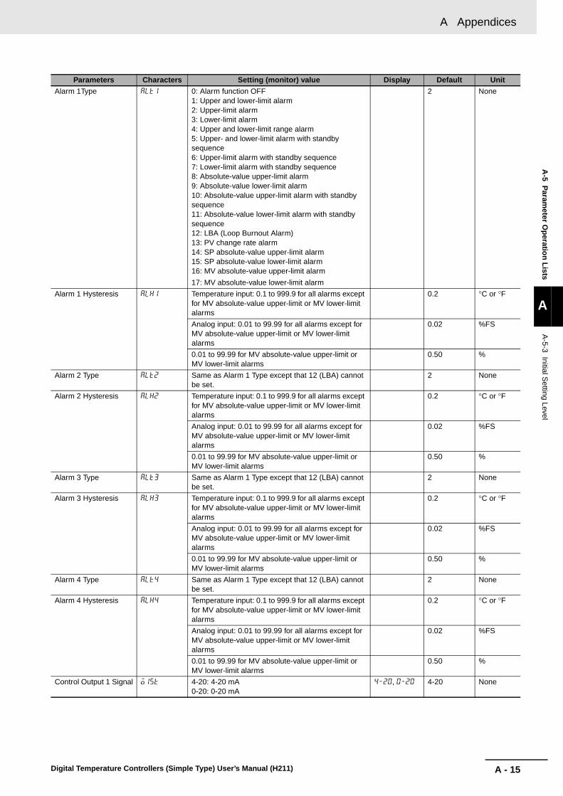
A - 15
A Appendices
Digital Temperature Controllers (Simple Type) User’s Manual (H211)
A-5 P
arameter O
peratio
n L
ists
A
A-5-3 Initial S
etting Level
Alarm 1Type alt1 0: Alarm function OFF1: Upper and lower-limit alarm2: Upper-limit alarm3: Lower-limit alarm4: Upper and lower-limit range alarm5: Upper- and lower-limit alarm with standby sequence6: Upper-limit alarm with standby sequence7: Lower-limit alarm with standby sequence8: Absolute-value upper-limit alarm9: Absolute-value lower-limit alarm10: Absolute-value upper-limit alarm with standby sequence11: Absolute-value lower-limit alarm with standby sequence12: LBA (Loop Burnout Alarm)13: PV change rate alarm14: SP absolute-value upper-limit alarm15: SP absolute-value lower-limit alarm16: MV absolute-value upper-limit alarm
17: MV absolute-value lower-limit alarm
2 None
Alarm 1 Hysteresis alh1 Temperature input: 0.1 to 999.9 for all alarms except for MV absolute-value upper-limit or MV lower-limit alarms
0.2 °C or °F
Analog input: 0.01 to 99.99 for all alarms except for MV absolute-value upper-limit or MV lower-limit alarms
0.02 %FS
0.01 to 99.99 for MV absolute-value upper-limit or MV lower-limit alarms
0.50 %
Alarm 2 Type alt2 Same as Alarm 1 Type except that 12 (LBA) cannot be set.
2 None
Alarm 2 Hysteresis alh2 Temperature input: 0.1 to 999.9 for all alarms except for MV absolute-value upper-limit or MV lower-limit alarms
0.2 °C or °F
Analog input: 0.01 to 99.99 for all alarms except for MV absolute-value upper-limit or MV lower-limit alarms
0.02 %FS
0.01 to 99.99 for MV absolute-value upper-limit or MV lower-limit alarms
0.50 %
Alarm 3 Type alt3 Same as Alarm 1 Type except that 12 (LBA) cannot be set.
2 None
Alarm 3 Hysteresis alh3 Temperature input: 0.1 to 999.9 for all alarms except for MV absolute-value upper-limit or MV lower-limit alarms
0.2 °C or °F
Analog input: 0.01 to 99.99 for all alarms except for MV absolute-value upper-limit or MV lower-limit alarms
0.02 %FS
0.01 to 99.99 for MV absolute-value upper-limit or MV lower-limit alarms
0.50 %
Alarm 4 Type alt4 Same as Alarm 1 Type except that 12 (LBA) cannot be set.
2 None
Alarm 4 Hysteresis alh4 Temperature input: 0.1 to 999.9 for all alarms except for MV absolute-value upper-limit or MV lower-limit alarms
0.2 °C or °F
Analog input: 0.01 to 99.99 for all alarms except for MV absolute-value upper-limit or MV lower-limit alarms
0.02 %FS
0.01 to 99.99 for MV absolute-value upper-limit or MV lower-limit alarms
0.50 %
Control Output 1 Signal o1st 4-20: 4-20 mA0-20: 0-20 mA
4-20, 0-20 4-20 None
Parameters Characters Setting (monitor) value Display Default Unit
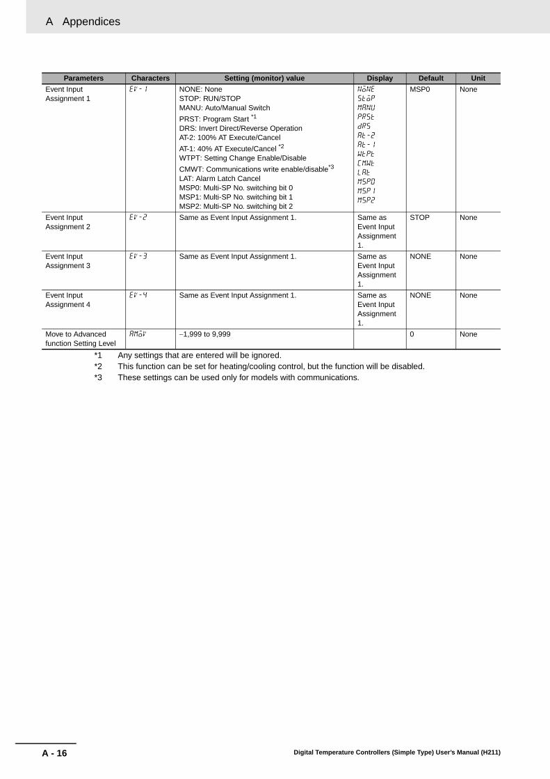
A Appendices
A - 16 Digital Temperature Controllers (Simple Type) User’s Manual (H211)
*1 Any settings that are entered will be ignored.*2 This function can be set for heating/cooling control, but the function will be disabled.*3 These settings can be used only for models with communications.
Event Input Assignment 1
ev-1 NONE: NoneSTOP: RUN/STOPMANU: Auto/Manual Switch
PRST: Program Start *1
DRS: Invert Direct/Reverse OperationAT-2: 100% AT Execute/Cancel
AT-1: 40% AT Execute/Cancel *2
WTPT: Setting Change Enable/Disable
CMWT: Communications write enable/disable*3
LAT: Alarm Latch CancelMSP0: Multi-SP No. switching bit 0MSP1: Multi-SP No. switching bit 1MSP2: Multi-SP No. switching bit 2
none
stop
manu
prst
drs
at-2
at-1
wtpt
cmwt
lat
msp0
msp1
msp2
MSP0 None
Event Input Assignment 2
ev-2 Same as Event Input Assignment 1. Same as Event Input Assignment 1.
STOP None
Event Input Assignment 3
ev-3 Same as Event Input Assignment 1. Same as Event Input Assignment 1.
NONE None
Event Input Assignment 4
ev-4 Same as Event Input Assignment 1. Same as Event Input Assignment 1.
NONE None
Move to Advanced function Setting Level
amov −1,999 to 9,999 0 None
Parameters Characters Setting (monitor) value Display Default Unit

A - 17
A Appendices
Digital Temperature Controllers (Simple Type) User’s Manual (H211)
A-5 P
arameter O
peratio
n L
ists
A
A-5-4 Manual Control Level
Parameters Characters Setting (monitor) value Display Default Unit
Manual MV −5.0 to 105.0 (standard)−105.0 to 105.0 (heating/cooling)
0.0 %
A-5-5 Advanced Function Setting Level
Parameters Characters Setting (monitor) value Display Default Unit
Parameter Initialization init OFF, FACT off, fact OFF None
Number of Multi-SP Points
mspu OFF(1), 2 to 8 off, 2 to 8 OFF None
SP Ramp Time Unit spru S: EU/secondM: EU/minuteH: EU/hour
s, m, h M None
Standby Sequence Reset
rest Condition A, condition B a, b Condition A None
Auxiliary Output 1 Open in Alarm
sb1n N-O: Close in alarmN-C: Open in alarm
n-o, n-c N-O None
Auxiliary Output 2 Open in Alarm
sb2n N-O: Close in alarmN-C: Open in alarm
n-o, n-c N-O None
HB ON/OFF hbu OFF, ON off, on ON None
Heater Burnout Latch hbl OFF, ON off, on OFF None
Heater Burnout Hysteresis
hbh 0.1 to 50.0 0.1 A
ST Stable Range st-b 0.1 to 999.9 15.0 °C or °Fα alfa 0.00 to 1.00 0.65 None
Integral/Derivative Time Unit
tidu 1, 0.1 1, 0.1 1 Second
Input Digital Filter inf 0.0 to 999.9 0.0 Second
Moving Average Count mav OFF, 2, 4, 8, 16, or 32 OFF Times
MV Display o-dp OFF, ON off, on OFF None
Automatic Display Return Time
ret OFF, 1 to 99 off, 1 to 99 OFF Second
Alarm 1 Latch a1lt OFF, ON off, on OFF None
Alarm 2 Latch a2lt OFF, ON off, on OFF None
Alarm 3 Latch a3lt OFF, ON off, on OFF None
Alarm 4 Latch a4lt OFF, ON off, on OFF None
Move to Protect Level Time
prlt 1 to 30 3 Second
Cold Junction Compensation Method
cjc OFF, ON off, on ON None
Alarm 1 ON Delay a1on 0 to 999 (0: ON delay disabled) 0 Second
Alarm 2 ON Delay a2on 0 to 999 (0: ON delay disabled) 0 Second
Alarm 3 ON Delay a3on 0 to 999 (0: ON delay disabled) 0 Second
Alarm 4 ON Delay a4on 0 to 999 (0: ON delay disabled) 0 Second
Alarm 1 OFF Delay a1of 0 to 999 (0: OFF delay disabled) 0 Second
Alarm 2 OFF Delay a2of 0 to 999 (0: OFF delay disabled) 0 Second
Alarm 3 OFF Delay a3of 0 to 999 (0: OFF delay disabled) 0 Second
Alarm 4 OFF Delay a4of 0 to 999 (0: OFF delay disabled) 0 Second
Auto/Manual Select Addition
amad OFF, ON off, on OFF None
Manual Output Method mant HOLD or INIT hold, init HOLD None
Manual MV Initial Value mani −5.0 to 105.0 for standard control
−105.0 to 105.0 for heating/cooling control
0.0 %
HS Alarm Use hsu OFF, ON off, on ON None
HS Alarm Latch hsl OFF, ON off, on OFF None
HS Alarm Hysteresis hsh 0.1 to 50.0 0.1 A
LBA Detection Time lba 0 to 9999 (0: LBA function disabled) 0 Second

A Appendices
A - 18 Digital Temperature Controllers (Simple Type) User’s Manual (H211)
LBA Level lbal Temperature input: 0.1 to 999.9 8.0 °C or °FAnalog input: 0.01 to 99.99 10.00 %FS
LBA Band lbab Temperature input: 0.0 to 999.9 3.0 °C or °FAnalog input: 0.00 to 99.99 0.20 %FS
Control Output 1 Assignment
out1 Relay Output or Voltage Output (for Driving SSR) *2 O None
NONE: No assignment none
O: Control output (heating) o
C-O: Control output (cooling) c-o
ALM1: Alarm 1 alm1
ALM2: Alarm 2 alm2
ALM3: Alarm 3 alm3
ALM4: Alarm 4 alm4
HA: Heater alarm (HB + HS) ha
HB: Heater burnout alarm (HB) hb
HS: Heater short alarm (HS) hs
S.ERR: Input error s.err
RS.ER: Remote SP input error *1 rs.er
P.END: Program End output *1 p.end
RUN: RUN output run
ALM: Integrated alarm alm
Current Output *2
NONE: Not assigned. none
O: Control output (heating) o
C-O: Control output (cooling) c-o
Control Output 2 Assignment
out2 Same as the Control Output 1 Assignment parameter.
Same as the Control Output 1 Assignment parameter.
NONE None
Auxiliary Output 1 Assignment
sub1 NONE: No assignment none ALM1*Controllers without HB and HS alarm detection: HA
None
O: Control output (heating) o
C-O: Control output (cooling) c-o
ALM1: Alarm 1 alm1
ALM2: Alarm 2 alm2
ALM3: Alarm 3 alm3
ALM4: Alarm 4 alm4
HA: Heater alarm (HB + HS) ha
HB: Heater burnout alarm (HB) hb
HS: Heater short alarm (HS) hs
S.ERR: Input error s.err
RS.ER: RSP input error *1 rs.er
P.END: Program end output *1 p.end
RUN: RUN output run
ALM: Integrated alarm alm
Auxiliary Output 2 Assignment
sub2 Same as the Auxiliary Output 1 Assignment parameter.
Same as the Auxiliary Output 1 Assignment parameter.
ALM2 None
Integrated Alarm Assignment
alma 0 to 255Alarm 1: +1Alarm 2: +2Alarm 3: +4Alarm 4: +8HB alarm: +16
HS alarm: +32Input error: +64
RSP input error: +128 *1
49 None
Parameters Characters Setting (monitor) value Display Default Unit

A - 19
A Appendices
Digital Temperature Controllers (Simple Type) User’s Manual (H211)
A-5 P
arameter O
peratio
n L
ists
A
*1 Any settings that are entered will be ignored.*2 The setting ranges are different for relay and voltage outputs (for driving SSR) and for current outputs.*3 Do not set this value.*4 The default setting is 4 when the settings are initialized.
PV Rate of Change Calculation Period
pvrp 1 to 999 20 Sampling period
Heating/Cooling Tuning Method
hctm 0: Same as heating control1: Linear2: Air cooling3: Water cooling
0 None
Minimum Output ON/OFF Band
ompw 0.0 to 50.0 1.0 %
PF Setting pf OFF: OFFRUN: RUNSTOP: STOPR-S: RUN/STOPAT-2: 100% AT execute/cancelAT-1: 40% AT execute/cancelLAT: Alarm Latch CancelA-M: Auto/manual
PFDP: Monitor/setting item *3
SHFT: Digit Shift Key
off
run
stop
r-s
at-2
at-1
lat
a-m
pfdp
shft
SHFT None
PV/SP No. 1 Display Selection
spd1 0: Nothing is displayed.1: PV/SP/Nothing displayed2: PV/Nothing displayed/Nothing displayed3: SP/SP (character display)/Nothing displayed4: PV/SP/MV5: PV/SP/Multi-SP No.
6: PV/SP/Soak time remain *1
7: PV/SP/Internal SP (ramp SP)8: PV/SP/Alarm value 1
1*4 None
PV/SP No. 2 Display Selection
spd2 Same as PV/SP No. 1 Display Selection. 0 None
MV Display Selection odsl O: MV (Heating)C-O: MV (Cooling)
o, c-o 0 None
PV Status Display Function
pvst OFF: OFFMANU: ManualSTOP: StopALM1: Alarm 1ALM2: Alarm 2ALM3: Alarm 3ALM4: Alarm 4ALM: OR of alarms 1 to 4
HA: Heater alarm *1
off
manu
stop
alm1
alm2
alm3
alm4
alm
ha
OFF None
SV Status Display Function
svst OFF: OFFMANU: ManualSTOP: StopALM1: Alarm 1ALM2: Alarm 2ALM3: Alarm 3ALM4: Alarm 4ALM: OR of alarms 1 to 4
HA: Heater alarm *1
off
manu
stop
alm1
alm2
alm3
alm4
alm
ha
OFF None
Display Refresh Period d.ref OFF, 0.25, 0.5, 1.0 off, 0.25, 0.5, 1.0
0.25 Second
A-5-6 Protect Level
Parameters Characters Setting (monitor) value Display Default Unit
Operation/Adjustment Protect oapt 0 to 3 0 None
Initial Setting/Communications Protect
icpt 0 to 2 1 None
Setting Change Protect wtpt OFF, ON off, on OFF None
PF Key Protect pfpt OFF, ON off, on OFF None
Changed Parameters Only chgp OFF, ON off, on OFF None
Parameters Characters Setting (monitor) value Display Default Unit

A Appendices
A - 20 Digital Temperature Controllers (Simple Type) User’s Manual (H211)
A-5-7 Communications Setting Level
Parameters Characters Setting (monitor) value Display Default Unit
Protocol Setting psel CWF: CompoWay/FMOD: Modbus
cwf, mod CompoWay/F
None
Communications Unit No. u-no 0 to 99 1 None
Communications Baud Rate bps 9.6, 19.2, 38.4, or 57.6 9.6, 9.2, 38.4, 57.6
9.6 kbps
Communications Data Length len 7, 8 7 Bit
Communications Stop Bits sbit 1, 2 2 Bit
Communications Parity prty NONE: NoneEVEN: EvenODD: Odd
none, eVen, odd
Even None
Send Data Wait Time sdwt 0 to 99 20 ms
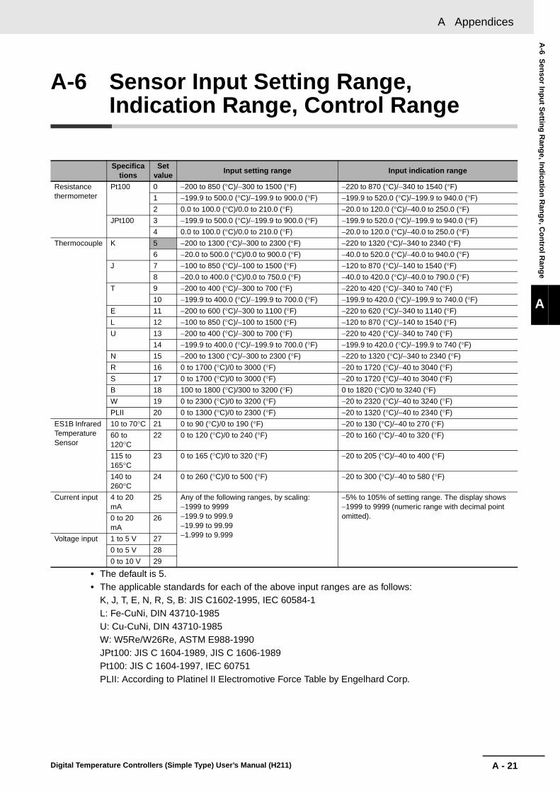
A - 21
A Appendices
Digital Temperature Controllers (Simple Type) User’s Manual (H211)
A-6 S
enso
r Inp
ut S
etting
Ran
ge, In
dicatio
n R
ang
e, Co
ntro
l Ran
ge
A
A-6 Sensor Input Setting Range, Indication Range, Control Range
• The default is 5.• The applicable standards for each of the above input ranges are as follows:
K, J, T, E, N, R, S, B: JIS C1602-1995, IEC 60584-1L: Fe-CuNi, DIN 43710-1985U: Cu-CuNi, DIN 43710-1985W: W5Re/W26Re, ASTM E988-1990JPt100: JIS C 1604-1989, JIS C 1606-1989Pt100: JIS C 1604-1997, IEC 60751PLII: According to Platinel II Electromotive Force Table by Engelhard Corp.
Specifications
Set value
Input setting range Input indication range
Resistance thermometer
Pt100 0 −200 to 850 (°C)/−300 to 1500 (°F) −220 to 870 (°C)/−340 to 1540 (°F)
1 −199.9 to 500.0 (°C)/−199.9 to 900.0 (°F) −199.9 to 520.0 (°C)/−199.9 to 940.0 (°F)
2 0.0 to 100.0 (°C)/0.0 to 210.0 (°F) −20.0 to 120.0 (°C)/−40.0 to 250.0 (°F)
JPt100 3 −199.9 to 500.0 (°C)/−199.9 to 900.0 (°F) −199.9 to 520.0 (°C)/−199.9 to 940.0 (°F)
4 0.0 to 100.0 (°C)/0.0 to 210.0 (°F) −20.0 to 120.0 (°C)/−40.0 to 250.0 (°F)
Thermocouple K 5 −200 to 1300 (°C)/−300 to 2300 (°F) −220 to 1320 (°C)/−340 to 2340 (°F)
6 −20.0 to 500.0 (°C)/0.0 to 900.0 (°F) −40.0 to 520.0 (°C)/−40.0 to 940.0 (°F)
J 7 −100 to 850 (°C)/−100 to 1500 (°F) −120 to 870 (°C)/−140 to 1540 (°F)
8 −20.0 to 400.0 (°C)/0.0 to 750.0 (°F) −40.0 to 420.0 (°C)/−40.0 to 790.0 (°F)
T 9 −200 to 400 (°C)/−300 to 700 (°F) −220 to 420 (°C)/−340 to 740 (°F)
10 −199.9 to 400.0 (°C)/−199.9 to 700.0 (°F) −199.9 to 420.0 (°C)/−199.9 to 740.0 (°F)
E 11 −200 to 600 (°C)/−300 to 1100 (°F) −220 to 620 (°C)/−340 to 1140 (°F)
L 12 −100 to 850 (°C)/−100 to 1500 (°F) −120 to 870 (°C)/−140 to 1540 (°F)
U 13 −200 to 400 (°C)/−300 to 700 (°F) −220 to 420 (°C)/−340 to 740 (°F)
14 −199.9 to 400.0 (°C)/−199.9 to 700.0 (°F) −199.9 to 420.0 (°C)/−199.9 to 740 (°F)
N 15 −200 to 1300 (°C)/−300 to 2300 (°F) −220 to 1320 (°C)/−340 to 2340 (°F)
R 16 0 to 1700 (°C)/0 to 3000 (°F) −20 to 1720 (°C)/−40 to 3040 (°F)
S 17 0 to 1700 (°C)/0 to 3000 (°F) −20 to 1720 (°C)/−40 to 3040 (°F)
B 18 100 to 1800 (°C)/300 to 3200 (°F) 0 to 1820 (°C)/0 to 3240 (°F)
W 19 0 to 2300 (°C)/0 to 3200 (°F) −20 to 2320 (°C)/−40 to 3240 (°F)
PLII 20 0 to 1300 (°C)/0 to 2300 (°F) −20 to 1320 (°C)/−40 to 2340 (°F)
ES1B Infrared Temperature Sensor
10 to 70°C 21 0 to 90 (°C)/0 to 190 (°F) −20 to 130 (°C)/−40 to 270 (°F)
60 to 120°C
22 0 to 120 (°C)/0 to 240 (°F) −20 to 160 (°C)/−40 to 320 (°F)
115 to 165°C
23 0 to 165 (°C)/0 to 320 (°F) −20 to 205 (°C)/−40 to 400 (°F)
140 to 260°C
24 0 to 260 (°C)/0 to 500 (°F) −20 to 300 (°C)/−40 to 580 (°F)
Current input 4 to 20 mA
25 Any of the following ranges, by scaling:−1999 to 9999−199.9 to 999.9−19.99 to 99.99−1.999 to 9.999
−5% to 105% of setting range. The display shows −1999 to 9999 (numeric range with decimal point omitted).0 to 20
mA26
Voltage input 1 to 5 V 27
0 to 5 V 28
0 to 10 V 29
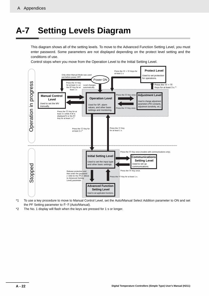
A Appendices
A - 22 Digital Temperature Controllers (Simple Type) User’s Manual (H211)
A-7 Setting Levels Diagram
This diagram shows all of the setting levels. To move to the Advanced Function Setting Level, you mustenter password. Some parameters are not displayed depending on the protect level setting and theconditions of use.Control stops when you move from the Operation Level to the Initial Setting Level.
*1 To use a key procedure to move to Manual Control Level, set the Auto/Manual Select Addition parameter to ON and setthe PF Setting parameter to a-m (Auto/Manual).
*2 The No. 1 display will flash when the keys are pressed for 1 s or longer.
Ope
ratio
n in
pro
gres
sS
topp
ed
Advanced Function Setting Level
Power ON
Initial Setting Level
Operation LevelAdjustment Level
Press the O Key once.
Press the O + M Keys for at least 1 s
Only when Manual Mode was used just before power OFF
Level changes automatically.
Protect Level
Manual Control Level
Press the O Key once.
Press the O Key for at least 1 s.
Press the O Key for at least 1 s or the S Key for at
least 1 s
Used to set the MV manually.
Used for SP, alarm values, and other basic settings and monitoring.
Press the O Key for at least 3 s while A-M is displayed*2 or the S Key for at least 1 s*1
Used to set protection for operations.
Used to change adjustment parameters (PID constants, adjustment sensitivity, etc.).
Press the O + M Keys for at least 3 s.*2
Release protection and then enter the password (−169) for the amoV (Move to Advanced Setting Level) parameter.
Used to set application functions.
Used to set the input type and other basic settings.
Press the O Key for at least 1 s.
Press the O Key for at least 3 s*2
Press the O Key once.
Press the O Key once (models with communications only).
Communications Setting Level
Used to set up communications.
A - 23
A Appendices
Digital Temperature Controllers (Simple Type) User’s Manual (H211)
A-7 S
etting
Levels D
iagram
A
A-5-7 C
omm
unications Setting Level

A Appendices
A - 24 Digital Temperature Controllers (Simple Type) User’s Manual (H211)
A-8 Parameter Flow
This section describes the parameters set in each level. Pressing the M Key at the last parameter ineach level returns to the top parameter in that level.
M
M
M
M
M
M
M
Press the O Key less than 1 s.
Communications Setting Level
Displayed only for models with communications. Changes are effective after cycling power or after a software reset.
Protocol Setting:Switches between CompoWay/F and Modbus.
Communications Unit No.
Communications Baud Rate
CompoWay/F only
Communications Data Length
Communications Stop Bits
Communications Parity
Send Data Wait Time
pselcwf
u-no1
bps9.6
len7
sbit2
prtyeven
sdwt20
M
M
M
M
M
M
M
M
M
M
M
M
M
M
M
M
M
M
M
M
M
M
M
M
M
M
M
M
M
M
M
M
M
M
M
M
M
M
M
M
M
M
M
M
M
M
M
M
M
M
M
Proportional Band (Cooling)
M
SP 4
M
SP 5
M
SP 6
M
SP 7
Integral Time (Cooling)
Derivative Time (Cooling)
M
Process Value Input Shift
Process Value/Set Point 1
Process Value/Set Point 2
*1
*1
Starting in manual mode.
ST (Self-tuning)
Power ON
Starting in automatic mode.
Manual Control Level
PID Control only
PV/MV
Press the O Key less than 1 s.
Press the O Key less than 1 s.Operation Level
Adjustment Level
AT Execute/Cancel
SP 0
SP 1
SP 2
SP 3
Proportional Band
Integral Time
PID settings
Derivative Time
Dead Band
Manual Reset ValueClear the offset during stabilization of P or PD control.
Hysteresis (Heating)
Hysteresis (Cooling)Hysteresis settings
SP Ramp Set Value
MV Upper Limit
MV Lower Limit
Auto/Manual SwitchPID control only.Added when auto/manual select addition is ON.
Multi-SP Set Point Selection
Set Point During SP Ramp
Press the O and M Keys for at least 3 s.
Protect Level
Press the O and M Keys for at least 1 s.
The time taken to move to the protect level can be adjusted by changing the "Move to protect level time" setting.
Operation/Adjustment Protect:Restricts displaying and modifying menus in operation, adjustment, and manual control levels.Initial Setting/Communications Protect:This protect level restricts movement to the initial setting, communications setting, and advanced function setting levels.
Setting Change Protect:Protects changes to setups by operating the front panel keys.
PF Key Protect
RUN/STOP
Alarm Value 1
Set
eith
er o
f the
se p
aram
eter
s.
Alarm Value Upper Limit 1
Alarm Value Lower Limit 1
Alarm Value 2
Set
eith
er o
f the
se p
aram
eter
s.
Alarm Value Upper Limit 2
Alarm Value Lower Limit 2
Alarm Value 3
Alarm Value Upper Limit 3
Alarm Value Lower Limit 3 S
et e
ither
of t
hese
par
amet
ers.
MV Monitor (Heating)
MV Monitor (Cooling)
Press theO Key for at least 1 s.
Press the O Key for less than 1 s.
Initial Setting Level
Input Type
Scaling Upper Limit
Scaling Lower Limit
Decimal Point
For input type of analog
Temperature Unit°C, °F
For input type of temperature
SP Upper Limit
SP Lower LimitLimit the set point
PID ON/OFF
Standard or Heating/Cooling
For input type of temperature, standard control, or PID
Control Period (Heating)
Control Period (Cooling)
Set the ON/OFF output cycle.
Direct/Reverse Operation
Alarm 1 Type
Alarm 1 Hysteresis
Press the O Key for at least 3 s.Other than the Auto/Manual Switch display
Press the S Key for at least 1 s.
Press the O Key or the S Key for at least 1 s.
*1. When the PF Setting parameter is set to A-M.
Press the O Key for at least 3 s.
Set
eith
er o
f the
se p
aram
eter
s.
Alarm Value Upper Limit 4
Alarm Value Lower Limit 4
Alarm Value 4
M
250
C
250
ins0.0
c-p8.0
c-i233
c-d40
M
M
M
p8.0
i233
d40
c-db0.0
of-r50.0
hys1.0
chys1.0
oapt0
icpt1
wtptoff
pfptoff
Changed Parameters OnlyM
chgpoff
M
sprtoff
ol-h100.0
ol-l0.0
atoff
sp-00
sp-10
sp-20
sp-30
sp-40
sp-50
sp-60
sp-70
M
sp-30
r-srun
in-t5
in-h100
in-l0
dp0
d-uc
sl-h1300
sl-l-200
cntlonof
s-hcstnd
ston
cp20
c-cp20
orevor-r
alt12
alh10.2
al-10
al1h0
al1l0
al-20
al2h0
al2l0
al-40
al4h0
al4l0
M
M
M
al-30
al3h0
al3l0
o0.0
c-o0.0
250
a-m
m-sp0
sp-m0
M
M
M
Communications Writing
Heater Current 1 Value Monitor
Heater Burnout Detection 1
Leakage Current 1 Monitor
HS Alarm 1
cmwtoff
ct10.0
M
hb10.0
lcr10
hs150.0
M
Heater Current 1 Value Monitor
Leakage Current 1 Monitor
ct-10.0
lcr10.0
M

A - 25
A Appendices
Digital Temperature Controllers (Simple Type) User’s Manual (H211)
A-8 P
arameter F
low
A
A-5-7 C
omm
unications Setting Level
M
M
M
M
M
M
M
M
M
M
M
M
M
M
M
M
M
M
M
M
PV/SP No. 1 Display Selection
PV/SP No. 2 Display Selection
M
M
M
Integral/Derivative Time Unit
M
M
M
M
M
M
M
M
M
M
M
M
M
Integrated Alarm Assignment
Moving Average Count
M
M
Manual Output Method
M
Manual MV Initial Value
M
M
M
M
M
M
alt22
initoff
a1ltoff
a2ltoff
a3ltoff
a4ltoff
prlt3
a1on0
a2on0
a3on0
a4on0
a1of0
a2of0
a3of0
a4of0
amadoff
manthold
mani0.0
pfshft
spd11
spd20
odslo
pvstoff
svstoff
d.ref0.25
lba0
lbal8.0
lbab3.0
out1o
out2none
sub1alm1
sub2alm2
alma49
M
M
Heating/Cooling Tuning Method
Minimum Output ON/OFF Band
M
M
M
pvrp20
hctmoff
ompw1.0
mspuoff
sprum
resta
sb1nn-o
sb2nn-o
st-b15.0
alfa0.65
tidu1
inf0.0
mavoff
M
M
o-dpoff
retoff
alh20.2
alt42
alh40.2
M
M
alt32
alh30.2
Control Output 1 Signalo1st4-20
M
cjcon
Press the O Key for at least 1 s.
Advanced Function Setting Level
Alarm 2 Type
Alarm 3 Type
Alarm 2Hysteresis
Alarm 3Hysteresis
Move by setting password (−169).
Parameter Initialization
Number of Multi-SP Points
SP Ramp Time Unit
Standby Sequence Reset
Auxiliary Output 1 Open in Alarm
Auxiliary Output 2 Open in Alarm
ST Stable Range
α
Input Digital Filter
MV Display
Automatic Display Return Time
Alarm 1 Latch
Alarm 2 Latch
Alarm 3 Latch
Move to Protect Level Time
Cold Junction Compensation Method
Alarm 1 ON Delay
Alarm 2 ON Delay
Alarm 3 ON Delay
Alarm 1 OFF Delay
Alarm 2 OFF Delay
Alarm 3 OFF Delay
Auto/Manual Select Addition
LBA Detection Time
LBA Level
LBA Band
Control Output 1 Assignment
Control Output 2 Assignment
PV Rate of ChangeCalculation Period
PF Setting
MV Display Selection
PV Status DisplayFunction
SV Status Display Function
Display RefreshPeriod
Alarm 4 Latch
Alarm 4 ON Delay
Alarm 4 OFF Delay
Auxiliary Output 1 Assignment
Auxiliary Output 2 Assignment
Alarm 4 Type
Alarm 4Hysteresis
M
M
amov0
Move to Advanced Function Setting Level:Displayed when initial setting/communications protect is set to 0.
M
*2. The default setting is 4 when the settings are initialized.
*2
M
M
hsuon
hsloff
hsh0.1
M
HS Alarm Use
HS Alarm Latch
HS Alarm Hysteresis
M
M
M
hbuon
hbloff
hbh0.1
HB ON/OFF
Heater Burnout Latch
Heater Burnout Hysteresis
M
M
M
M
ev-1msp0
ev-2stop
ev-3none
ev-4none
Event Input Assignment 1
Event Input Assignment 2
Event Input Assignment 3
Event Input Assignment 4
A Appendices
A - 26 Digital Temperature Controllers (Simple Type) User’s Manual (H211)

Index-1Digital Temperature Controllers (Simple Type) User’s Manual (H211)
I
Index

Index-2 Digital Temperature Controllers (Simple Type) User’s Manual (H211)
A
AD Converter Error ........................................................A-7Adjustment Level .........................................................A-13Advanced Function Setting Level ................................A-17alarms (standard alarms) .............................................. 1-3auxiliary outputs .......................................................... 2-12auxiliary outputs 1 and 2 ............................................. 2-16
C
characteristics ...............................................................A-3communications .......................................................... 2-17Communications Setting Level ....................................A-20CompoWay/F ...............................................................A-20control outputs ............................................................... 1-3control outputs 1 and 2 .......................................2-10, 2-15control ranges ..............................................................A-21CT
dimensions ..............................................................A-5E54-CT1 ..........................................................A-5E54-CT3 ..........................................................A-5
specifications ...........................................................A-5CT input ....................................................................... 2-17current transformer (CT) ................................................A-5Current Value Exceeds ..................................................A-8
D
Digit Shift Key ................................................................ 3-7dimensions .................................................................... 2-2Display Range Exceeded ..............................................A-7displays ......................................................................... 3-5Down Key (D Key) ........................................................ 3-6
E
error displays .................................................................A-6event inputs ..........................................................1-3, 2-16
F
front panel ..................................................................... 3-4E5CC ....................................................................... 3-4E5EC ....................................................................... 3-4
H
HB alarm ............................................................... A-2, A-8HB and HS alarms ................................................ 1-3, A-2heater burnout alarm .....................................................A-2heater short alarm .........................................................A-2HS alarm ............................................................... A-2, A-8
I
I/O configuration ............................................................ 1-4indication ranges .........................................................A-21
indicators ....................................................................... 3-5Initial Setting Level ......................................................A-14Input Error .....................................................................A-6input power supply ....................................................... 2-12input sensor types ......................................................... 1-3inputs ........................................................................... 2-14installation ..................................................................... 2-2
mounting the Terminal CoversE5CC ............................................................... 2-4E5EC ............................................................... 2-5
mounting to the panelE5CC ............................................................... 2-4E5EC ............................................................... 2-5
insulation block diagrams ............................................ 2-18integrated alarm ............................................................ 1-3
K
KeysD Down Key ........................................................... 3-6O Level Key ............................................................ 3-6M Mode Key ........................................................... 3-6S Shift Key (PF Key) .............................................. 3-6U Up Key ................................................................ 3-6
L
Level Key (O Key) ........................................................ 3-6
M
main functions ............................................................... 1-3Manual Control Level ...................................................A-17Memory Error ................................................................A-8Modbus-RTU ...............................................................A-20Mode Key (M Key) ........................................................ 3-6model number legends .................................................. 1-5mounting the Terminal Covers
E5CC ....................................................................... 2-4E5EC ....................................................................... 2-5
N
No. 1 display .................................................................. 3-4No. 2 display .................................................................. 3-4No. 3 display .................................................................. 3-4
O
operation indicators ................................................3-4, 3-5Operation Level ...........................................................A-12options ..................................................................2-9, 2-13
P
panel cutout ................................................................... 2-3parameter flow .............................................................A-24parameter operation lists .............................................A-12PF Key (S Key) .....................................................3-6, 3-7

Index-3Digital Temperature Controllers (Simple Type) User’s Manual (H211)
power supply ............................................................... 2-14Protect Level ............................................................... A-19
R
ratings ........................................................................... A-2RS-485 .................................................................2-17, A-4
S
sampling cycle .......................................................1-2, A-3sensor input ................................................................ 2-11sensor input setting ranges ......................................... A-21setting levels diagram ................................................. A-22Shift Key (S Key) ......................................................... 3-7specifications ................................................................ A-2
T
terminal arrangement .................................................... 2-6terminal block wiring examples
E5CC ....................................................................... 2-6E5EC ..................................................................... 2-10
troubleshooting ............................................................. A-9
U
Up Key (U Key) ............................................................ 3-6using the terminals ........................................................ 2-6
W
wiring .......................................................................... 2-14wiring precautions ....................................................... 2-14

Index-4 Digital Temperature Controllers (Simple Type) User’s Manual (H211)


Authorized Distributor:
In the interest of product improvement, specifications are subject to change without notice.
Cat. No. H211-E1-02 0612
© OMRON Corporation 2012 All Rights Reserved.
OMRON Corporation Industrial Automation Company
OMRON ELECTRONICS LLCOne Commerce Drive Schaumburg,IL 60173-5302 U.S.A.Tel: (1) 847-843-7900/Fax: (1) 847-843-7787
Regional HeadquartersOMRON EUROPE B.V.Wegalaan 67-69-2132 JD HoofddorpThe NetherlandsTel: (31)2356-81-300/Fax: (31)2356-81-388
Contact: www.ia.omron.comTokyo, JAPAN
OMRON ASIA PACIFIC PTE. LTD.No. 438A Alexandra Road # 05-05/08 (Lobby 2), Alexandra Technopark, Singapore 119967Tel: (65) 6835-3011/Fax: (65) 6835-2711
OMRON (CHINA) CO., LTD.Room 2211, Bank of China Tower, 200 Yin Cheng Zhong Road, PuDong New Area, Shanghai, 200120, ChinaTel: (86) 21-5037-2222/Fax: (86) 21-5037-2200