Digital Switching Systems - Steven...
16
Digital Switching Systems ECS III Programmable Digital Multiplexing System
Transcript of Digital Switching Systems - Steven...

Digital Switching SystemsECS III
ProgrammableDigital
MultiplexingSystem

Contents
Introduction . . . . . . . . . . . . . . . . . . . . . . . . . 1
Features & Benefits. . . . . . . . . . . . . . . . . . . . 3
Additional Software Features . . . . . . . . . . . . . 4
Hardware Features . . . . . . . . . . . . . . . . . . . . 4
Circuit Configurations . . . . . . . . . . . . . . . . . . . 5
Typical Wiring Diagram . . . . . . . . . . . . . . . . . . 6
General Specifications . . . . . . . . . . . . . . . . . . 6
Connection Diagram . . . . . . . . . . . . . . . . . . . . 7
Dimensional Specifications . . . . . . . . . . . . . . . 8
Configuration Sheet . . . . . . . . . . . . . . . . . . . 10
Contact Information. . . . . . . . . . . . . . . . . . . .12

Carling Technologies™
www.carlingtech.com3
New ECS III
New ECS III
Carling Technologies continues a heritage of innovation with the next generation in switching technology…the
Electronic Control System III, (ECS III).
The ECS III features the latest in digital multiplex technology, creating a safer and fully configurable control
system for the marine environment. With numerous advantages to both the marine manufacturer and the
end operator, the ECS III truly defines a revolution in switch technology. While providing a flexible system
with a new aesthetic look, the ECS III also simplifies and enhances the end operator’s switching environ-
ment. Beyond product differentiation, the ECS III eliminates complex wiring while increasing switching fea-
tures and functionality, and simplifies troubleshooting.
As future product enhancements necessitate more complex switching applications, Carling Technologies has
the answer. Turn the page to open your eyes to a revolution in switching technology…
The Carling Technologies’ ECS III.

Carling Technologies™
www.carlingtech.com4
The ECS III
A basic ECS III consists of at least one Electronic Control Processor (ECP)™, Operator Control Module (OCM)™ and ElectronicCommunications Cable (ECC)™.
Electronic Control Processor (ECP)The heart of the ECS is the Electronic Control Processor (ECP).The ECP receives switching commands from the OCM(s), trans-lates the commands and activates or de-activates the appropri-ate circuits in the boat’s electrical system. One ECP can controlup to 16 separate circuits/accessories. Up to four ECP’s can belinked together to provide control for up to 64 separate cir-cuits/accessories. Each circuit is protected by its own resettablethermal circuit protector within the ECP.
Manual circuit-override switches are designed into the ECP. In theunlikely event of a system failure, these switches provide a fastand convenient way to override the ECS’ electronics, withoutbypassing the unit’s circuit protection (in accordance with ABYC* recommendations). The manual circuit-override can also be usedto switch ON/OFF circuits, without powering up the entire ECS.
The ECP is factory programmable to meet your application needs.
Standard Operator Control Modules (OCMs)Standard OCMs are backlit and are offered in two configurations:four button and eight button. OCMs include LEDs, which are illu-minated when an individual button is activated. Numerous OCMcolors, markings and illumination options are available.
Custom Operator Control Modules (OCMs)Custom OCM shapes, colors and configurations can bedesigned for your panel to meet your switching, marking andillumination needs.
Electronic Communications Cable (ECC)Switching commands are transmitted from the OCM(s) to theECP via the ECC. The ECC can be supplied in any length to suityour application needs.
* ABYC: American Boat & Yacht Council
ECS III

Carling Technologies™
www.carlingtech.com5
Each ECS contains a base software program which has been developed to provide boatbuilders and end users with the maximumbenefit of digital switching technology. The following are some of the standard software features provided with every Carling ECS:
ECS III Features and Benefits
Load Protection and Circuit Shutdown Voltage monitoring software and battery drain protection arestandard, and can be assigned to individual buttons on theOCM. This feature minimizes the chances of the voltage leveldropping to a non-operational low level, by shutting down lowpriority circuits during low voltage situations.
The software constantly monitors the battery voltage and elec-trical components that are being operated by the ECP. The nor-mal operating range for the 12V ECP to function properly isbetween 9 volts and 16 volts. The normal operating range forthe 24V ECP to function properly is between 18 and 32 volts.
The ECP can automatically turn OFF components at a specificvoltage level. Each circuit can be assigned one of three levelsof battery protection. By assigning a priority level to each cir-cuit, the ECS knows which electrical circuit to turn OFF, and inwhich order, when the battery voltage drops below the pro-grammed Low Voltage Level. Priority Level One Circuits willalways remain ON.
The operator can override the Circuit Shut Down by pressingthe corresponding button on the OCM.
Sleep ModeThe ECP provides battery protection by reducing the amount ofcurrent that the ECS draws when it is not being used.
a. Shut Down: The ECP can be programmed to shut down aftera customer defined set time.
b. Restart: The ECP will reboot its normal operations.
Dedicated Bilge Pump Circuits
Many boats utilizing bilge pumps have an automatic float switchto turn the bilge pump ON in the event of a high water situa-tion. The ECS has provisions to connect the auto float switch tothe same circuit protector as the manual bilge pump, eliminat-ing the need for additional circuit protection, or even worse,leaving the auto bilge circuit unprotected. The float switch con-nection is independent of the ECS electronics, and power willbe maintained to this connection even if the master powerswitch on the ECS is turned OFF. Additionally, the switched linedoubles as a sensor which can be configured to detect if thefloat switch has turned the bilge pump ON and will indicate thison the keypad (in accordance with ABYC recommendations).
Key Benefits of the ECS III:
• Simplified operator control, comfort and safety
• Ease of installation
• Reduced labor installation time
• Simplified wiring resulting in weight reduction and space savings
• Ease of serviceability and troubleshooting
• Programmable and expandable switching functions
Standard Software Features

Carling Technologies™
www.carlingtech.com6
Ignition Sensing The ECS can be tied to the ignition switchso some features only work when the keyis in the ON or accessory position. Othercircuits (ie, bilge) would work regardlessof ignition switch position.
Backlighting OCM backlighting is controlled by either aparticular switch button press or by theposition of the ignition switch.
Low Battery Sensing The ECS can be configured to sense bat-tery voltage and turn OFF non-criticalloads as the battery starts to drain. Thelevels (x2) at which circuits are turnedOFF are customer configurable.
Automatic Shutdown The ECS can be configured to turn OFF allfunctions after a prescribed period ofinactivity.
Configurable Circuits (relays) can be configured toAlways On Circuits be ON all of the time. This allows the ECP
to be used as a distribution panel (ie.for stereo memory) as well as a switchingsystem.
Bilge Pump Auto The ECS will detect when a bilge pumpDetect Circuit has been turned ON by a float switch, &
will indicate this on the OCM (as requiredby the ABYC).
Cloned Switches Individual circuits can be controlled withmultiple switch buttons in multiple loca-tions.
Dimming The ECS can be configured to dim thefunction indication LEDs to a preset valueby turning on a particular circuit, typicallythe navigation or anchor lights.
Lock-out Circuits Lock-out Circuits can be configured to notwork if another specific circuit is ON. Thisis an ideal configuration for motor revers-ing circuits.
Tripped Circuit The ECS will detect when a circuit Breaker Sensing breaker has tripped and will indicate the (pending) trip with a rapid flashing LED on the OCM.
Remote-Reset Using an auto-reset thermal circuit Circuit Breaker breaker, the ECS is capable of remotely (pending) resetting circuits.
Hardware Features
ECS III Software and Hardware Features
Additional Standard Software Features
Multiple ECPs Up to 4 ECPs, totalling up to 64 cir-cuits per ECS.
Multiple OCMs Up to 16 OCMs per ECS, using stan-dard 4 & 8 button boards.
Circuit Protection Carling Technologies’ thermal circuit breakers.
Auxiliary Digital Input Each ECP has a digital input for con-nection of an external sensor or dis-crete switch.
Dedicated Bilge One switched output for Pump Circuits (x2) manual control and one unswitched
output for float switch connection ona common circuit breaker.
Override Switches (x8) Provides manual conventional switch-ing as a back-up for critical circuits.Maintains circuit protection.
Master Power ON-OFF Turns the ECS OFF to avoid battery Switch drain, during extended periods of
non-use.
Carling Technologies™
www.carlingtech.com7
ECS III Circuit Configurations
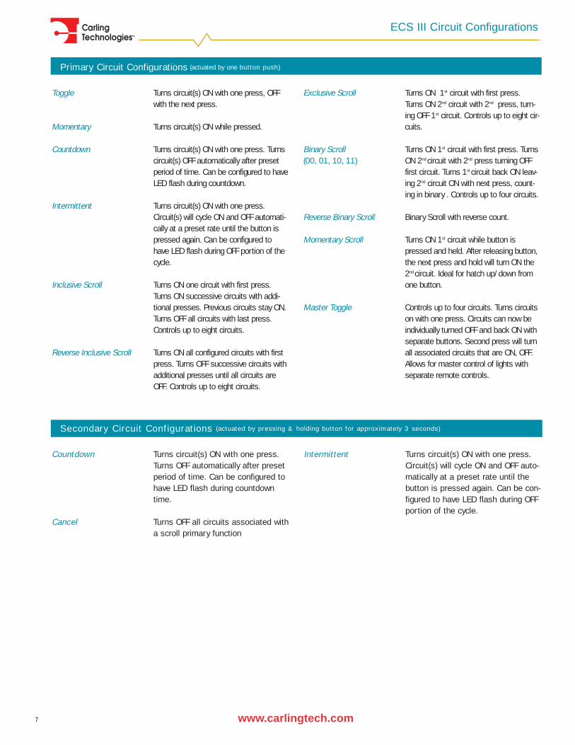
Primary Circuit Configurations (actuated by one button push)
Toggle Turns circuit(s) ON with one press, OFFwith the next press.
Momentary Turns circuit(s) ON while pressed.
Countdown Turns circuit(s) ON with one press. Turnscircuit(s) OFF automatically after presetperiod of time. Can be configured to haveLED flash during countdown.
Intermittent Turns circuit(s) ON with one press.Circuit(s) will cycle ON and OFF automati-cally at a preset rate until the button ispressed again. Can be configured tohave LED flash during OFF portion of thecycle.
Inclusive Scroll Turns ON one circuit with first press.Turns ON successive circuits with addi-tional presses. Previous circuits stay ON.Turns OFF all circuits with last press.Controls up to eight circuits.
Reverse Inclusive Scroll Turns ON all configured circuits with firstpress. Turns OFF successive circuits withadditional presses until all circuits areOFF. Controls up to eight circuits.
Exclusive Scroll Turns ON 1st circuit with first press.Turns ON 2nd circuit with 2nd press, turn-ing OFF 1st circuit. Controls up to eight cir-cuits.
Binary Scroll Turns ON 1st circuit with first press. Turns (00, 01, 10, 11) ON 2nd circuit with 2nd press turning OFF
first circuit. Turns 1st circuit back ON leav-ing 2nd circuit ON with next press, count-ing in binary . Controls up to four circuits.
Reverse Binary Scroll Binary Scroll with reverse count.
Momentary Scroll Turns ON 1st circuit while button ispressed and held. After releasing button,the next press and hold will turn ON the2nd circuit. Ideal for hatch up/down fromone button.
Master Toggle Controls up to four circuits. Turns circuitson with one press. Circuits can now beindividually turned OFF and back ON withseparate buttons. Second press will turnall associated circuits that are ON, OFF.Allows for master control of lights withseparate remote controls.
Countdown Turns circuit(s) ON with one press.Turns OFF automatically after presetperiod of time. Can be configured tohave LED flash during countdowntime.
Cancel Turns OFF all circuits associated witha scroll primary function
Intermittent Turns circuit(s) ON with one press.Circuit(s) will cycle ON and OFF auto-matically at a preset rate until thebutton is pressed again. Can be con-figured to have LED flash during OFFportion of the cycle.
Secondary Circuit Configurations (actuated by pressing & holding button for approximately 3 seconds)

Carling Technologies™
www.carlingtech.com8
ECS III Wiring Diagram & Specifications
Electrical
Environmental (Meets EMC Directive 89/336/EEC, as amended by 92/31/EEC and 93/68/EEC)
MechanicalPC Board .093 thick FR-4Relay 12V, 8 positions @ 15A and 25A
24V, 8 positions @ 10A and 16ACover Housing (ECP) PBT/ABS, BlackCover Gasket (ECP) Translucent silicone rubber, durome-
ter: 40±5Cover Screws Cover screws 302SSConnectors (ECP) Deutsch DT13-4P, -12PA, -08PA
Connectors (OCM) Deutsch DT13-4PPower Lug Brass Alloy, electroplated bright tinPower Lug Hardware Brass Alloy Hex Nuts, Lock Washers,
Flat WashersInformation Labels Opaque polyester, white background,
black and red printingTypical Actuation Force 890 gramsof Buttons on Keypad
Recommended System Voltage 12V nominal system: 9-16V
24V nominal system: 18-32VSwitch Life (keypad) exceeds one million operations per
buttonECP Current 100A maximum
Standby Current - OFF 15mA max. in sleep modeMemory Type Flash
Operating Temperature -30°C to + 50°CStorage Temperature -40°C to + 50°CHumidity MIL-STD-202F
Salt Spray MIL-STD-202FRCA Abrasion Wear Test (keypad) 100 times
CLB-Series Thermal Circuit Protection
OVERLOAD TRIP TIME
100% NO TRIP
150% TRIP IN 1 HR
200% 5 - 35 SEC.
300% 1.5-9 SEC.
400% 0.9 - 5.5 SEC.
500% 0.5 - 3.5 SEC.
600% 0.3 - 2.8 SEC.
Pos.+
Neg.-
Battery
Loads
Ignition
Loads
Pos.+
OCM #2(optional)
Operator Control Module OCM #1
14awg or 16awg recommended
Circuit Breakers
Carling Technologies recommends using a Deep Cycle & Starting battery with 950mac (or750cca) and a RC+100 minutes minimum.
Electronic Control Processor (ECP)
Battery cutoff switchor circuit breaker 2
Neg.-
GENERAL NOTES:1. ECS must be wired directly to battery. Do not branch ECS power from starter lines!2. Circuit protect system per ABYC standards.3. Diagram represents recommended wiring only.4. A hard reset of the system may be necessary should power become unstable.
Recommended Mounting 1. The ECP should be mounted in an area
easily accessible to the operator to allow:
a. access to integrated manual circuitoverride switches for critical loads.
b. access to thermal protectors, so theycan be reset if a circuit has an overloadcondition.
2. Suggested ECP mounting: 45° to 90° (ver-tical), or on a hinged door for easy acces-sibility.
3. If cover of ECP is removed, after replacingcover, torque screws to 8 - 10 in-lbs.
ECS III Typical Wiring Diagram
Circuit Protection CLBXX311ANNRARating 3 to 40A, 125-250VAC, 32VDC Approvals UL/CULDielectric Strength 1500 VAC/ 1 minuteInterrupting capacity 1000 ampsResettable overload capacity 10x rated currentInsulation Resistance 100M ohmsVoltage drop < 0.25 V

Carling Technologies™
www.carlingtech.com9
ECS III Connection Diagram
Connection Diagram
Microcontroller(Sends switch
contact position and receives LED on/off
information)
OCM Address Configuration
Module
Microcontroller(Sends switch
contact position and receives LED on/off
information)
Keypad Switch Button
Backlighting LED
OCM Address Configuration
Module
MULTIPLE OCMS AS REQUIRED
Function Indication LED
OCM ECC
Function Indication LED
4 Wire bus
Keypad Switch Button
Backlighting LED
Load
ConfigurationMemory
(Stores custom program)
Battery Voltage Monitor Relay Driver
Override Switch
-
Battery
+ Input Voltage Power Stud
Power Relay
Override Switch
Load
Output Connector
+
- Input Voltage Power Stud
Power Relay
Thermal Circuit Breaker
Communicationsinterface to
microcontroller(Sends LED information,
receives switch contact position)
Battery Voltage Monitor
ConfigurationMemory
(Stores custom program)
Output Connector
-
Relay Driver
Microcontroller(Processes all
information from switch press,
timers, voltage levels etc. and
controls appropriate relays
and LEDs)
AUX Digital Input
+ Input Voltage Power Stud
Battery
+
Input Filter
CB Voltage Monitor
- Input Voltage Power Stud
MULTIPLE ECPS AS REQUIRED
AUX Digital Input
ECP
Thermal Circuit Breaker
CB Voltage Monitor
Input Filter
Output Connector
Output Connector
Microcontroller(Processes all
information from switch press,
timers, voltage levels etc. and
controls appropriate relays
and LEDs)
Communicationsinterface to
microcontroller(Sends LED information,
receives switch contact position)

Carling Technologies™
www.carlingtech.com10
ECS III Dimensional Specifications
Dimensional Specifications
9.291 [235.99]
DEUTSCH P/N DT13-08PA(MATING CONNECTOR IS DT06-08SA)
DEUTSCH P/N DT13-12PA(MATING CONNECTOR IS DT06-12SA)
11.820 [300.23]
2X1/4 - 20 UNC-2A POWER STUD
DEUTSCH P/N DT13-4P(MATING CONNECTOR IS DT06-4S SUPPLIED WITH ECC)
3.033 [77.04]
ALL STAINLESS STEELHARDWARE
.0802.03
DEUTSCH P/N DT13-12PA(MATING CONNECTOR IS DT06-12SA)
DEUTSCH P/N DT13-08PA(MATING CONNECTOR IS DT06-08SA)
3.05177.48
2X1/4 - 20 UNC-2A POWER STUD
12.586319.68
DEUTSCH P/N DT13-4P(MATING CONNECTOR IS DT06-4S SUPPLIED WITH ECC)
ALL STAINLESS STEELHARDWARE
[5.59] 4X .220
MASTERPOWER SWITCH
4.880 [123.95]
11.280 [286.51]
OVERIDE SWITCHES (QTY 8)
PUSH TO RESET CIRCUIT BREAKER(QTY 16)
Recommended System Voltage 9-16VSwitch Life (keypad) exceeds one million operations per
buttonECP Current 100A maximumStandby Current - OFF 15mA in sleep modeMemory Type Flash

Carling Technologies™
www.carlingtech.com11
ECS III Dimensional Specifications
Dimensional Specifications
R .250[6.35]
[13.34].525
.920[23.37]
[13.34]
IMAGE AREAMAX
.700
[7.62].300
[17.78]
[15.24]
TEXT AREAMAX
POSITION 2
POSITION 4
2 4
OCMORIENTATION
4
2
3
1
0°180°
270°
3
1
1 3
4 2
13
2
4
.525
1.39035.31
.600.300
90°
.890[22.61]
1.465[37.21]
3.110[79.01]
POSITION 3
POSITION 1
2.100[53.34]
2.000[50.8] 2.375
[60.33]
1.188[30.16]
[7.62]
.164-32 X 1-1/2" LONG 2 PLCS
[22.86]
.525[13.34]
POSITION 2 6.35
.164-32 X 1-1/2" LONG 2 PLCS
[13.34]
POSITION 4
POSITION 8
NAV/ANCLIGHTS
DOCK
1
2
[7.62].300
[15.24]
.300[7.62]
.600
3
270°
2
1
7
4 8
7
21
5
6
5
90°1
7
8 6
3180°
7
13
24
8
650°
8
2
4
.525
POSITION 6
5
.700[17.78]
436
IMAGE AREAMAX
.900
TEXT AREAMAX
POSITION 3
POSITION 5
POSITION 7
POSITION 1
3.30583.95
1.59440.49
2.40060.96
3.50088.9
R .250
1.75044.45
1.39035.31
2.15054.61
6.210157.73
OCMORIENTATION

Carling Technologies™
www.carlingtech.com12
ECS Configuration SheetCarling Technologies™
Carling Technologies™
Parameter Default
Ignore Ignition ON
Backlight On Ignition OFF
Inactivity Power-Down Time 10 Hours
Count-Down On Time 3 Minutes
Intermittent On-Time 1 Minute
Intermittent Off-Time 1 Minute
Low Voltage Stage 1 9.8V
Low Voltage Stage 2 9.2V
Circuit # Function Master Override Load Current Inrush Load Preference CB Rating Shutdown Priority Std/Accy Comments
1
2
3
4
5
6
7
8
9
10
11
12
13
14
15
16
Notes:Master override is available on up to 8 circuits per ECP.If inrush current is unknown, please provide as much information about the load as possible such as MFG, MFG P/N etc.Available circuit breaker ratings are: 3.0A, 4.0A, 5.0A, 6.0A, 7.0A, 8.0A, 10A, 12A, 13A, 15A, 20A & 25A.Add information for additional circuits, If more than 16 circuits are requiredCircuit numbers do not correspond to actual connections to the ECS. Refer to customer kit drawing for connection details.
Electronic Control SystemConfiguration Sheet
0 (No Shutdown) to 54 hours in 10 minute increments
2. ENTER LOAD CIRCUIT SPECIFICATIONS (see notes.)
Type Of Boat:
3 seconds to 12 minutes, 42 seconds in 3 second increments
3 seconds to 12 minutes, 42 seconds in 3 second increments
helvetica
6.0V to Stage 1 -.1V in .1V increments
3 seconds to 12 minutes, 42 seconds in 3 second increments
Range
ON/OFF
ON/OFF
*** Please fax completed forms to 860-793-9231 or email to: [email protected] ***
CUSTOMER INFORMATION:
SUBMITTED BY:
1. ENTER GLOBAL PARAMETERS
Setting
APPLICATION INFORMATION:
Panel Source & Contact:
Address: City, State, ZIP:
Phone: email:
Contact Name: Company Name:
Name/Company: Phone/email:
# Of Operator Stations: Total # Of Controlled Loads: Total # Of OCMs:
Boat Length:Boat Model(s):
Carling Technologies™
www.carlingtech.com13
ECS Configuration Sheet
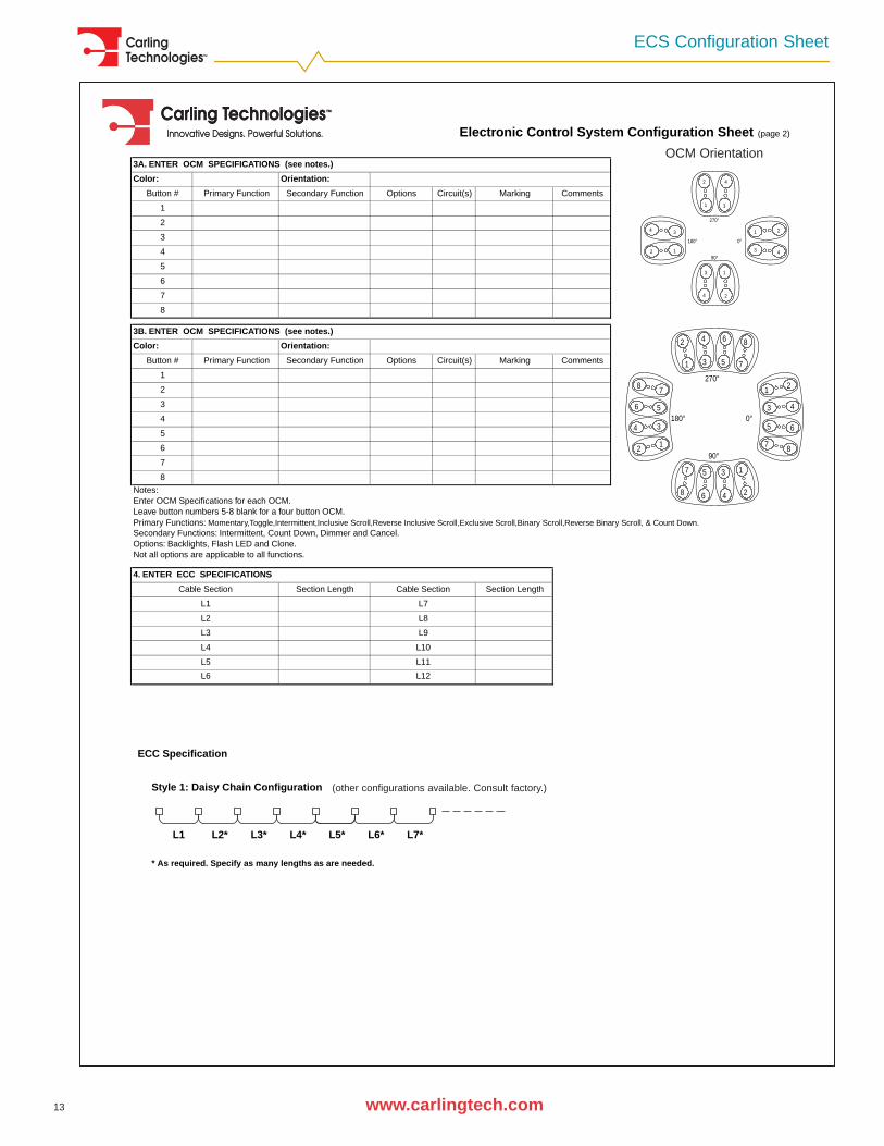
3A. ENTER OCM SPECIFICATIONS (see notes.)
Color: Orientation:
Button # Primary Function Secondary Function Options Circuit(s) Marking Comments
1
2
3
4
5
6
7
8
3B. ENTER OCM SPECIFICATIONS (see notes.)
Color: Orientation:
Button # Primary Function Secondary Function Options Circuit(s) Marking Comments
1
2
3
4
5
6
7
8
Notes:Enter OCM Specifications for each OCM. Leave button numbers 5-8 blank for a four button OCM.Primary Functions: Momentary,Toggle,Intermittent,Inclusive Scroll,Reverse Inclusive Scroll,Exclusive Scroll,Binary Scroll,Reverse Binary Scroll, & Count Down. Secondary Functions: Intermittent, Count Down, Dimmer and Cancel.Options: Backlights, Flash LED and Clone.Not all options are applicable to all functions.
Section Length Section Length
L7
Cable Section
4. ENTER ECC SPECIFICATIONS
Electronic Control System Configuration Sheet (page 2)
L1
L5
L6
L9
L10
L11
L12
L3
L8
L4
Cable Section
L2
*** Please fax completed forms to 860-793-9231 or email to: [email protected] ***
OCM Orientation
2 4
4
2
3
1
0°180°
270°
3
1
1 3
4 2
13
2
4
90°
3
270°
2
1
7
4 8
7
21
5
6
5
90°1
7
8 6
3180°
7
13
24
8
650°
8
2
4
5 436
ECC Specification
Style 1: Daisy Chain Configuration
L1 L2* L3* L4* L5* L6* L7*
* As required. Specify as many lengths as are needed.
(other configurations available. Consult factory.)

Carling Technologies™
www.carlingtech.com14
Carling leads the way in digital switching technology with the ECS III
Multiplex switching technology offers many benefits over traditional analog switching, to both the manufactur-
er and to the end user. The marine manufacturer benefits from decreased wiring time, expense, weight, and
complexity, while the end operator benefits from increased control, switching flexibility and a safer boating
environment.
Leading the revolution in the marine market for digital switching technology, Carling Technologies’ ECS III
delivers on a promise to simplify marine equipment. Don’t wait for the future to drive you, catch the wave
and switch to a simpler world of switching technology.
For more information:
For more information on the ECS III, please:
• visit our web site at www.carlingtech.com,
• email us at [email protected],
• or call us at the location closest to you, listed on the back cover of this catalog.
Let us show you how we can put the power of digital switching in your control!
Contact UsCarling Technologies™
Carling Technologies™

www.carlingtech.com
Warranty PolicyCarling Technologies, Inc. (Seller) warrants that goods sold hereunder shall be free of defects in material and workmanship for one year from date of shipment.In the event of such defects, the Seller’s only obligation shall be the replacement or the cost of the defective goods, themselves, excluding, without limitation, labor costs, whichare or may be required in connection with the replacement or reinstallation of the goods. This warranty is the Seller’s sole obligation and excludes all other remedies or war-ranties, express or implied, including warranties of merchantability and fitness for a particular purpose, whether or not purposes or specifications are described herein. ThisWarranty expressly excludes any and all incidental, special and/or consequential damages of any nature. Seller further disclaims any responsibility for injury to person or dam-age to or loss of property or value caused by any product which has been subjected to misuse, negligence, or accident; or misapplied, or modified or repaired by a person or per-sons not authorized by the Seller or which have been improperly installed.
Other Carling Technologies Catalogs
Switches and Controls
This catalog includes the complete line of Carlingswitch brand electri-
cal switches for most any power switching need. Included are rocker,
toggle, pushbutton, rotary and sealed switches with a wide variety of
circuits, ratings, terminations, colors, illuminations, and legends.
Worldwide certifications, UL1500, CE marked.
Circuit Protection
This catalog details Carling circuit protection products including
hydraulic/magnetic circuit breakers and ground fault breakers.
Breakers range from 0.1 to 700 amps Hi-inrush delay curves, Front
Panel Snap-in Mounting styles, Rockerguard Bezels, Dual-Coil func-
tions, and Quick Connect Terminals are included. Worldwide certifi-
cations, including UL1500, UL489 and CE marked. A Carling thermal
circuit protection catalog is also available.
Power Distribution Centers
This catalog includes the complete line of standard AC and DC Power
Distribution Centers and Battery Disconnects. All products are
designed to fit into industry standard racks, from 1RU to 3RU, and
utilize Carling hydraulic/magnetic circuit breakers.

Worldwide HeadquartersCarling Technologies, Inc., Connecticut, USA(860) 793-9281, fax: (860) 793-9231e-mail: [email protected]
www.carlingtech.com
Eastern U.S. and Eastern Canada:(860)586-8413, fax: (860) 586-8513e-mail: [email protected]
Midwestern U.S.:(815) 653-9333, fax: (815) 653-2206e-mail: [email protected]
Western U.S., Western Canada, Mexico and South America:(972) 509-0807, fax: (972) 509-0368e-mail: [email protected]
Europe/Middle East/Africa HeadquartersCarling Technologies Ltd., Devon, EnglandInt + 44 1392-364422, fax: Int + 44 1392-364477e-mail: [email protected]
Central Europe:Carling Technologies GmbHInt + 49 6104-959157, fax: Int + 49 6104-959158e-mail: [email protected]
Southern Europe:Carling Technologies SARLInt + 33 3 84 43 0706, fax: Int + 33 3 84 43 14 44e-mail: [email protected]
Asia-Pacific HeadquartersCarling Technologies, Asia-Pacific Ltd., Kowloon, Hong KongInt + 852-2737-2277, fax: Int + 852-2736-9332e-mail: [email protected]
ChinaInt + 86-21-6390-6916, fax: Int + 86-21-6390-6918e-mail: [email protected]
JapanInt + 813-5789-2925, fax: Int + 813-5789-2927e-mail: [email protected]
ECS_2_03