Digital servo - Diversified Machine Systems Fagor Automation’s digital servo drive system is the...
16
Digital servo drive system
Transcript of Digital servo - Diversified Machine Systems Fagor Automation’s digital servo drive system is the...

Digital servodrive system
2
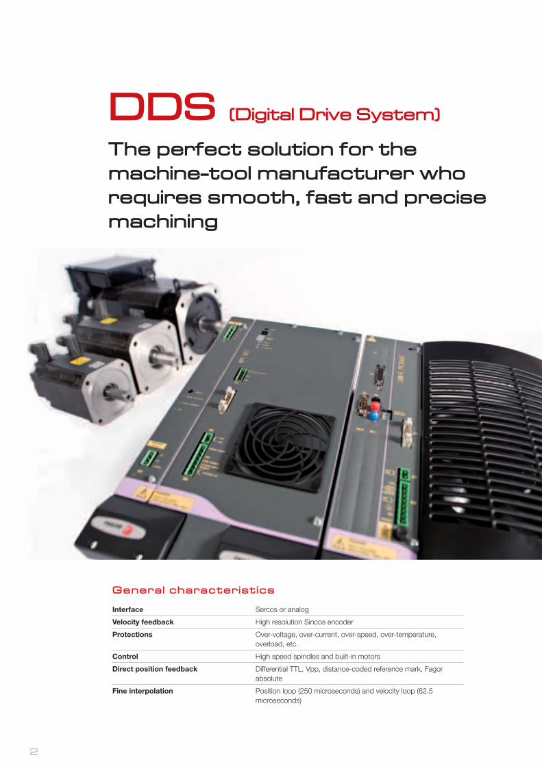
DDS (Digital Drive System)
The perfect solution for the machine-tool manufacturer who requires smooth, fast and precise machining
Interface Sercos or analog
Velocity feedback High resolution Sincos encoder
Protections Over-voltage, over-current, over-speed, over-temperature, overload, etc.
Control High speed spindles and built-in motors
Direct position feedback Differential TTL, Vpp, distance-coded reference mark, Fagor absolute
Fine interpolation Position loop (250 microseconds) and velocity loop (62.5 microseconds)
General characteristics

3
Solutions tailored to your machine
The Fagor Automation’s digital servo drive system is the perfect solution for the machine manufacturer who requires smooth, fast and precise machining. It offers maximum efficiency using a single power supply for governing the spindle and the axes of the machine .
• PS Non-regenerative power supply.• XPS Regenerative power supply.• RPS Regulated regenerative power supply with a power factor (cosine of j) near 1 (boosting power supply).
Fagor AXD and SPD drives offer the STO (Safe Torque Off) safety function defined in compliance with the standard IEC 61800-5-2. This safety function may be used to safely disconnect the motor torque and it is always active.
When a machine requires a certain Performance Level «PL d» or a certain safety integrity level «SIL 2», it requires an external safety controller«PL d» or «SIL 2» that disconnects the motor torque in two different channels. The safety controller will watch the status of each channel (only when demanding the STO) keeping the motor torque off in case of failure.
Safety function
Axis controlAXD drives can govern the axes of the machine with FKM motors, covering a range from 1.7 Nm to 115 Nm (1.0 kW to 24.1 kW) with a rated speed from 2000 rpm to 6000 rpm.
FM7 E01 Power (kW) 3.7 5.5 … 9 11 … 22 22 … 37 21.5 … 60
Flange (mm) 150 180 230 300 350
Shaft height (mm) 100 112 160 180 225
FM9 E01 Power (kW) 37 ... 55 71 … 130
Flange (mm) 300 450
Shaft height (mm) 180 225
FM7 E03 Power (kW) 5.5 ... 7.5 11 … 22
Flange (mm) 180 230
FM7 HS3 Power (kW) 7.5 11 … 22
Flange (mm) 180 230
FKM Torque (Nm) 1.7 ... 3.2 6.3 ... 11.6 8.9 ... 23.5 32 ... 100 68 ... 115
Power (kW) 1 ... 2 2 ... 4.9 2.8 ... 7.4 6.7 ... 25.1 14.2 ... 24.1
Flange (mm) 80 110 130 180 230
Spindle control SPD drives are used to govern the spindle with FM7 and FM9 motors.
• E01series Spindle motors with Delta (triangle) winding.• E03 series Spindle motors with Y-D (star-triangle) winding.• HS3 series Direct drive motors (without pulleys), with hollow shaft for cooling the tool from the spindle and Y/Delta (star /
triangle) winding.

Fagor CNC
4
Sercos
Completely integrated solutionA unique integrated platform for all your needs
Fagor Automation’s unique integrated platform brings together every electronic element of your machine: the CNC , digital servo motors and drives, linear and angular feedback and ensures seamless integration, guaranteeing robust machine design and extreme performance to obtain maximum efficiency.
.
Servo Drive Systems
Axis motors Spindle motor
Feedback systems
Three phase 50/60 Hz mains connection(400-10% to 460+10%)
Mains filter
Choke
Ballast
Capacitor module
These elements work in perfect harmony and intelligently selecting and executing the machining algorithms to exceed user’s expectations – EVERYTIME.

5
D I G I T A L S E R V O D R I V E S Y S T E M
Completely integrated solution
Reliable, robust and durable: Total qualityIn order to ensure superior system performance under tough ambient conditions (temperature, vibrations etc.), various product testing methods like HALT-HASS process (unique, accelerated product reliability test methods) for detecting and resolving any product weakness are used ensuring very high product reliability at launch.
The quality, robustness and reliability of Fagor Automation systems have been accredited and certified by many renowned agencies (TüV, CE, etc.).
Continuous innovation to meet our customer’s needsA major part of Fagor Automation’s successful history is due to our constant investment commitment in company’s infrastructure and R&D+i (Research, Development and innovation). This allows us to continuously develop leading products for the marketplace.
Fagor’s technical center in Spain, called AOTEK, has also jointly participated with other domestic and international research centers and universities on many prestigious technical projects like POWER-OM, ReBORN, CHAMELEON and IMPELER etc.
Fagor Automation recently increased it’s R&D+i capabilities by adding 2 new technical centers in Ivrea (Italy) and Beijing (China).
Commitment to environmentDevelopment and implementation of advanced technologies has helped us create more “GREEN” designs without needing any batteries or fans hence removing such environmentally unfriendly components demonstrating our commitment to preserving and protecting the environment.
Using regenerative power supplies with our digital servo drive systems eliminates the heat loss generated by resistors during motor braking while returning that energy to the power source- hence providing economical savings while helping the environment.
6
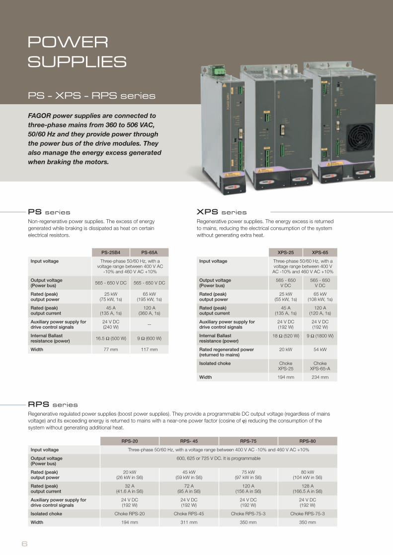
PS seriesNon-regenerative power supplies. The excess of energy generated while braking is dissipated as heat on certain electrical resistors.
FAGOR power supplies are connected to three-phase mains from 360 to 506 VAC, 50/60 Hz and they provide power through the power bus of the drive modules. They also manage the energy excess generated when braking the motors.
XPS seriesRegenerative power supplies. The energy excess is returned to mains, reducing the electrical consumption of the system without generating extra heat.
RPS seriesRegenerative regulated power supplies (boost power supplies). They provide a programmable DC output voltage (regardless of mains voltage) and its exceeding energy is returned to mains with a near-one power factor (cosine of j) reducing the consumption of the system without generating additional heat.
PS-25B4 PS-65A
Input voltage Three-phase 50/60 Hz, with a voltage range between 400 V AC
-10% and 460 V AC +10%
Output voltage(Power bus) 565 - 650 V DC 565 - 650 V DC
Rated (peak)output power
25 kW (75 kW, 1s)
65 kW (195 kW, 1s)
Rated (peak) output current
45 A (135 A, 1s)
120 A (360 A, 1s)
Auxiliary power supply for drive control signals
24 V DC (240 W) —
Internal Ballast resistance (power) 16.5 � (500 W) 9 � (600 W)
Width 77 mm 117 mm
XPS-25 XPS-65
Input voltage Three-phase 50/60 Hz, with a voltage range between 400 V
AC -10% and 460 V AC +10%
Output voltage(Power bus)
565 - 650 V DC
565 - 650 V DC
Rated (peak)output power
25 kW (55 kW, 1s)
65 kW (108 kW, 1s)
Rated (peak) output current
45 A (135 A, 1s)
120 A (120 A, 1s)
Auxiliary power supply for drive control signals
24 V DC (192 W)
24 V DC (192 W)
Internal Ballast resistance (power)
18 � (520 W) 9 � (1800 W)
Rated regenerated power (returned to mains)
20 kW 54 kW
Isolated choke ChokeXPS-25
ChokeXPS-65-A
Width 194 mm 234 mm
RPS-20 RPS- 45 RPS-75 RPS-80
Input voltage Three-phase 50/60 Hz, with a voltage range between 400 V AC -10% and 460 V AC +10%
Output voltage(Power bus)
600, 625 or 725 V DC. It is programmable
Rated (peak)output power
20 kW (26 kW in S6)
45 kW (59 kW in S6)
75 kW (97 kW in S6)
80 kW (104 kW in S6)
Rated (peak) output current
32 A (41.6 A in S6)
72 A (95 A in S6)
120 A (156 A in S6)
128 A (166.5 A in S6)
Auxiliary power supply for drive control signals
24 V DC (192 W)
24 V DC (192 W)
24 V DC (192 W)
24 V DC (192 W)
Isolated choke Choke RPS-20 Choke RPS-45 Choke RPS-75-3 Choke RPS-75-3
Width 194 mm 311 mm 350 mm 350 mm
POWER SUPPLIES
PS - XPS - RPS series

7
Input of the direct feedback for the position loop (Optional)Feedback of the actual (real) position of an axis, usually by connecting a linear or rotary encoder.
Encoder simulator output (Optional)It provides a number of pulses per motor revolution that may be set by parameter (any value between 1 and 16,384 pulses/turn, programmable I0, differential TTL.
Motor feedback inputIt reads the signals coming from an encoder mounted on the motor to know its exact position and speed.
AXD seriesDigital drive that can govern a synchronous motor in speed and position working as an axis.
SPD seriesDigital drive that can govern a synchronous or an asynchronous motor in speed and position working as a spindle.
The drives have a modular and stackable design. They are connected directly to the power bus provided by the power supply and provide the motor with three-phase voltage with a variable frequency to control the speed and the position.
AXD 1.08 AXD 1.15 AXD 1.25 AXD 1.35 AXD 2.50 AXD 2.75 AXD 3.100 AXD 3.150
I rated (A) 4 7.5 12.5 17.5 25 37.5 50 75
I peak (0.5s) (A) 8 15 25 35 50 75 100 150
Voltage supply for control circuits 24 V DC (between 21 V DC and 28 V DC)
Consumption of control circuits 0.90 A 0.90 A 0.90 A 0.90 A 1.25 A 1.25 A 2.00 A 2.00 A
Width 77 mm 77 mm 77 mm 77 mm 117 mm 117 mm 234 mm 234 mm
SPD 1.25
SPD 1.35
SPD 2.50
SPD 2.75
SPD 2.85
SPD 3.100
SPD 3.150
SPD 3.200
SPD 3.250
I rated (S1) at 4 kHz 16 23.1 31 42 50 70 90 121 135
I rated (S1) at 8 kHz 13 18 27 32 37 56 70 97 108
I S6 - 40% 4 kHz 20.8 30 40.3 54.6 65 91 117 157.3 175.5
I S6 - 40% 8 kHz 16.9 23.4 35.1 41.6 48.1 72.8 91 126.1 140.4
Voltage supply for control circuits 24 V DC (between 21 V DC and 28 V DC)
Consumption of control circuits 0.90 A 0.90 A 0.90 A 0.90 A 0.90 A 2.00 A 2.00 A 2.00 A 2.00 A
Width 77 mm 77 mm 117 mm 117 mm 117 mm 234 mm 234 mm 234 mm 234 mm
Connector for RS-232 serial line connectionTo connect with a PC for system parameter setting and monitoring.
SERCOS interface connectorTo transmit position, velocity and torque commands. The use of optical fiber ensures full immunity against noise and very simple wiring between modules.
AXIS AND SPINDLEDRIVES
AXD - SPD series

8
FM7 - FM9 asynchronous motors may be used on all kinds of machine-tool spindles, providing the high reliability and best efficiency that the application may demand.
Its highly robust design, the use of high precision bearings (special bearings) and other elements used in their design make it possible to use this motor in a wide range of rated power.
• E01 series Spindle motors with Delta (triangle) winding.• E03 series Spindle motors with Y-Delta (star-triangle) winding.• HS3 series Direct drive motors (without pulleys), with hollow shaft for cooling the tool from the spindle and Y/Delta (star /triangle)
winding.
FM7 E03 / FM7 HS3 FM7 E01 FM9 E01
Thermal protection(meets IEC 60034-6 standard)
NTC thermistor NTC thermistor Thermistor KTY84-130
Level of vibration(meets IEC 60034-14 standard)
V3 V5 - V10 (standard) V3 - V5 (optional)
V5
Type of construction(meets IEC 60034-7 standard)
Horizontal: IM B5 Vertical: IM V1
Horizontal: IM B3, IM B5, IM B35 Vertical: IM V1, IM V5, IM V15
Horizontal: IM B3, IM B5, IM B35 Vertical: IM V1, IM V5, IM V15, IM V3, IM V6, IM V36
Electrical insulation of the winding(meets IEC 60034 standard)
Class F ( 155 °C / 311 °F ) Class F (155 °C / 311 °F) Class F (155 °C / 311 °F)
Degree of protection(meets IEC 60034-5 standard)
IP44 IP44 IP54
Feedback Incremental TTL encoder of 1024 ppt
1024 ppt incremental TTL encoder (standard) 1024 ppt sinusoidal 1Vpp encoder (optional)
1024 ppt sinusoidal 1Vpp encoder
General characteristics
SPINDLE MOTORS
FM7 - FM9 series

9
FM7 EO3 - FM7 HS3 seriesS P I N D L E M O T O R S
FM7 E03 and FM7 HS3 motors have forced fan cooling and Y/Delta (star / triangle) winding. They can reach speeds of up to 15,000 rpm.
FM7 HS3 motors are especially designed to be mounted on the column for direct transmission without pulleys. The tool is secured with a coupling and they have a hole on the shaft for tool cooling.
Rated power S1 (kW)
Rated powerS6, 40% (kW)
Rated torque S1 (Mn)
Rated current (Arms)
Base speed (rpm)
Maximum speed (rpm)
Inertia [kg cm2]
FM7-D055-S1D0-E03 5.5 7.7 10 35 13.1 20.3 20.7 1,500 4,000 15,000 210
FM7-D075-S1D0-E03 7.5 11 13 47.7 17.9 26.5 25.8 1,500 4,000 15,000 260
FM7-D110-S1D0-E03 11 15.5 20 70 26.3 38 40 1,500 4,000 12,000 690
FM7-D150-S1D0-E03 15 22 26 95.5 35.8 46.4 45.7 1,500 4,000 12,000 690
FM7-D185-S1D0-E03 18.5 26 32 117.8 44.2 49.2 49.2 1,500 4,000 12,000 890
FM7-D220-S1D0-E03 22 33 40 140.1 52.2 62.3 61.7 1,500 4,000 12,000 1,080
FM7-D075-S1D0-HS3 7.5 11 13 47.7 17.9 26.5 25.8 1,500 4,000 15,000 260
FM7-D110-S1D0-HS3 11 15.5 20 70 26.3 38 40 1,500 4,000 12,000 690
FM7-D185-S1D0-HS3 18.5 26 32 117.8 44.2 49.2 49.2 1,500 4,000 12,000 890
FM7-D220-S1D0-HS3 22 33 40 140.1 52.2 62.3 61.7 1,500 4,000 12,000 1,080
FM7 EO3 - FM7 HS3 series

10
FM7 E01 - FM9 E01 motors have forced fan cooling and Delta (triangle) winding, with a rated power between 55 kW and 130 kW. They can reach speeds of up to 9,000 rpm.
FM7 E01 motors provide a rated power between 55 kW and 130 kW and can reach speeds of up to 9,000 rpm.
FM9 E01 motors provide a rated power between 55 kW and 130 kW and can reach speeds of up to 4,500 rpm.
Rated power S1 (kW)
Rated power S6, 40% (kW)
Rated torque S1 (Mn)
Rated current (Arms)
Base speed (rpm)
Maximum speed (rpm)
Inertia[kg cm2]
FM7 A037-xx-E01 3.7 5.5 23.5 12.4 1,500 9,000 140
FM7 A055-xx-E01 5.5 7.7 35 14.6 1,500 9,000 210
FM7 A075-xx-E01 7.5 11 47.7 19.8 1,500 9,000 260
FM7 A090-xx-E01 9 13 57.4 25.1 1,500 9,000 330
FM7 A110-xx-E01 11 15.5 70 27.9 1,500 9,000 690
FM7 A150-xx-E01 15 22 95.5 39.3 1,500 8,000 690
FM7 A185-xx-E01 18.5 26 117.8 47.4 1,500 8,000 890
FM7 A220-xx-E01 22 33 140 61.4 1,500 8,000 1,080
FM7 A300-xx-E01 30 45 191 82.1 1,500 6,500 2,310
FM7 A370-xx-E01 37 56 235 89.9 1,500 6,500 2,660
FM7 A510-xx-E01 51 71 325 115.1 1,500 5,000 4,730
FM7 B120-xx-E01 12 18.5 114.6 35 1,000 8,000 890
FM7 B170-xx-E01 17 25 162.3 47.2 1,000 8,000 1,080
FM7 B220-xx-E01 22 33 210 64.9 1,000 6,500 2,310
FM7 B280-xx-E01 28 42 267.4 78.2 1,000 6,500 2,660
FM7 C215-xx-E01 21.5 29 410.6 87.8 500 5,000 4,730
FM7 C270-xx-E01 27 37 515.7 116.9 500 5,000 5,840
FM7 E600-xx-E01 60 80 458.4 117.4 1,250 5,000 8,720
FM9 B037-xx-E01 37 45 350 74.7 1,000 5,000 3,000
FM9 B055-xx-E01 55 72 525.2 104.4 1,000 5,000 6,900
FM9 B071-xx-E01 71 105 678 134.8 1,000 4,500 14,790
FM9 A100-xx-E01 100 136 636.6 190 1,500 4,500 14,790
FM9 B113-xx-E01 113 153 1,079 215 1,000 4,500 23,260
FM9 A130-xx-E01 130 178 827.6 246.9 1,500 4,500 19,300
FM7 EO1 - FM9 EO series
FM7 EO1 - FM9 EO1 seriesS P I N D L E M O T O R S

L
Q
S LB
C
H
KL
L
Q
LBS
11
Dimensions in mm
L LB C H Q S
FM7 A037-xx-E01 499 150h7 100 250 60 28h6
FM7 A055-xx-E01 486 180h7 112 269 80 32h6
FM7 A075-xx-E01 546 180h7 112 269 110 48h6
FM7 A090-xx-E01 586 180h7 112 269 110 48h6
FM7 A110-xx-E01 571 230h7 160 343 110 48h6
FM7 A150-xx-E01 571 230h7 160 343 110 48h6
FM7 A185-xx-E01 633 230h7 160 343 110 48h6
FM7 A220-xx-E01 671 230h7 160 343 110 48h6
FM7 A300-xx-E01 769 300h7 180 407 140 60m6
FM7 A370-xx-E01 809 300h7 180 407 140 60m6
FM7 A510-xx-E01 842.5 350h7 225 540 140 70m6
FM7 B120-xx-E01 633 230h7 160 343 110 48h6
FM7 B170-xx-E01 671 230h7 160 343 110 48h6
FM7 B220-xx-E01 769 300h7 180 407 140 60m6
FM7 B280-xx-E01 809 300h7 180 407 140 60m6
FM7 C215-xx-E01 842.5 350h7 225 540 140 70m6
FM7 C270-xx-E01 892.5 350h7 225 540 140 70m6
FM7 E600-xx-E01 1,065.5 350h7 225 540 140 65m6
FM9 B037-xx-E01 944 300 160 420,3 100 55
FM9 B055-xx-E01 1,218.5 300 180 476 140 65
FM9 B071-xx-E01 1,259 450 225 660 140 75
FM9 A100-xx-E01 1,259 450 225 660 140 75
FM9 B113-xx-E01 1,444 450 225 660 140 75
FM9 A130-xx-E01 1,354 450 225 660 140 75
L LB KL Q S
FM7-D055-S1D0-E03 475 180h7 158 60 28h6
FM7-D075-S1D0-E03 506 180h7 164 60 28h6
FM7-D110-S1D0-E03 556 230h7 183 80 38h6
FM7-D150-S1D0-E03 556 230h7 183 80 38h6
FM7-D185-S1D0-E03 618 230h7 183 80 38h6
FM7-D220-S1D0-E03 665 230h7 183 80 38h6
FM7-D075-S1D0-HS3 715 180h7 158 60 28h6
FM7-D110-S1D0-HS3 751 230h7 183 70 38h6
FM7-D185-S1D0-HS3 813 230h7 183 70 38h6
FM7-D220-S1D0-HS3 851 230h7 183 70 38h6
FM7 EO3 - FM7 HS3 series
FM7 EO1 - FM9 EO1series
12
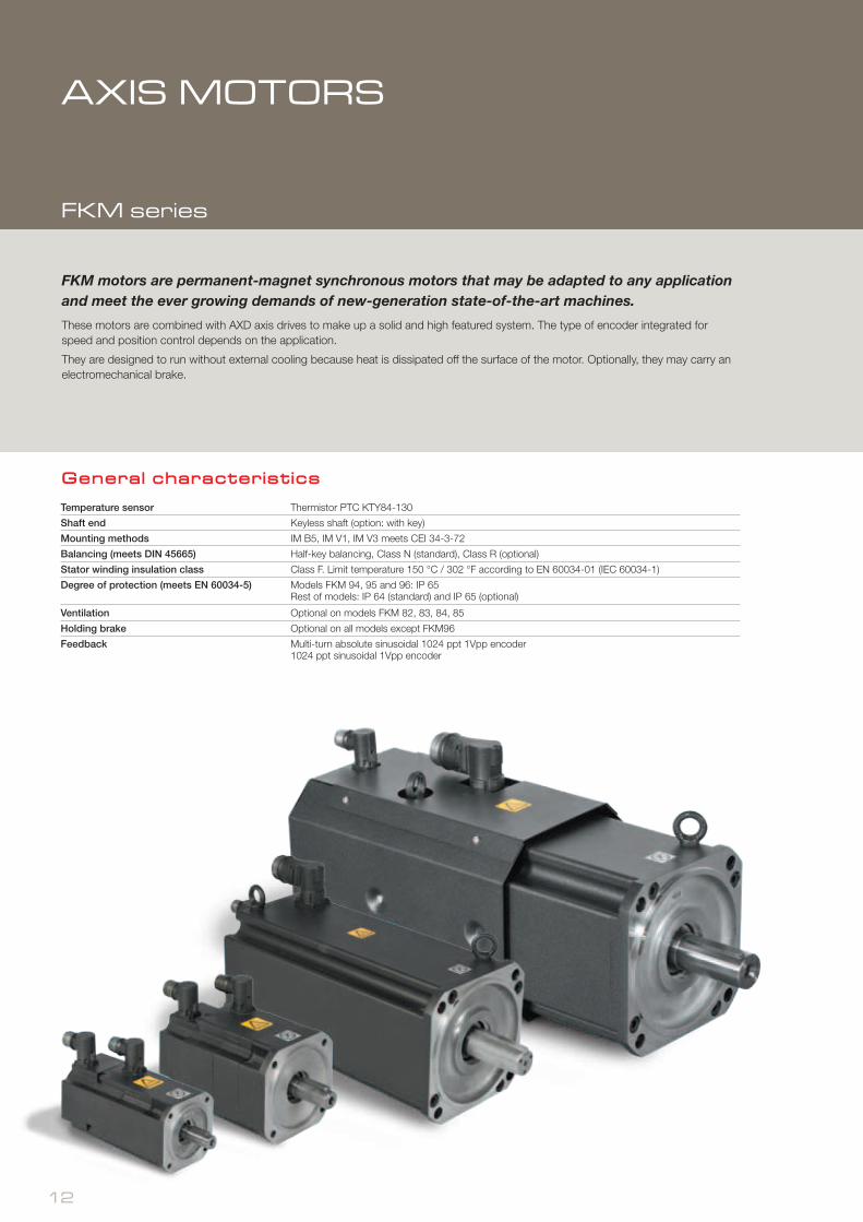
FKM motors are permanent-magnet synchronous motors that may be adapted to any application and meet the ever growing demands of new-generation state-of-the-art machines.
These motors are combined with AXD axis drives to make up a solid and high featured system. The type of encoder integrated for speed and position control depends on the application.
They are designed to run without external cooling because heat is dissipated off the surface of the motor. Optionally, they may carry an electromechanical brake.
Temperature sensor Thermistor PTC KTY84-130
Shaft end Keyless shaft (option: with key)
Mounting methods IM B5, IM V1, IM V3 meets CEI 34-3-72
Balancing (meets DIN 45665) Half-key balancing, Class N (standard), Class R (optional)
Stator winding insulation class Class F. Limit temperature 150 °C / 302 °F according to EN 60034-01 (IEC 60034-1)
Degree of protection (meets EN 60034-5) Models FKM 94, 95 and 96: IP 65Rest of models: IP 64 (standard) and IP 65 (optional)
Ventilation Optional on models FKM 82, 83, 84, 85
Holding brake Optional on all models except FKM96
Feedback Multi-turn absolute sinusoidal 1024 ppt 1Vpp encoder1024 ppt sinusoidal 1Vpp encoder
General characteristics
AXIS MOTORS
FKM series

E
LAC1
ØN
ØD
ØM
13
FKM series
MODEL Stall torque [Nm]
Peak torque[Nm]
Stall current [Arms] / Peak current [Arms] IInertia /
with brake [kg cm2]2000 rpm 3000 rpm 4000 rpm 4500 rpm 5000 rpm 6000 rpm
FKM 21 1.7 7 2.8 / 11 1.6 / 1.72
FKM 22 3.2 13 2.4 / 10 4.0 / 16 4.5 / 18 2.9 / 3.02
FKM 42 6.3 25 4.6 / 19 6.9 / 28 8.5 / 34 8.5 / 9.04
FKM 44 11.6 47 4.6 / 19 8.2 / 33 10.7 / 43 16.7 / 17.24
FKM 62 8.9 35 7.1 / 28 9.3 / 37 13.1 / 52 16 / 17.5
FKM 64 16.5 66 6.5 / 26 12.1 / 48 16.2 / 64 29.5 / 30.65
FKM 66 23.5 94 10.5 / 42 16.4 / 66 43 / 44.15
FKM 82 32 96 13.2 / 39 19.8 / 59 26.4 / 79 103 / 134.8
FKM 82 V (*) 40 96 33.0 / 79 103 / 134.8
FKM 83 41 123 17.0 / 51 27.1 / 81 150 / 181.8
FKM 83 V (*) 60 123 39.6 / 81 150 / 181.8
FKM 84 52 156 21.5 / 64 32.2 / 96 197 / 228.8
FKM 84 V (*) 80 156 33 / 64 49.5 / 96 197 / 228.8
FKM 85 74 222 29.3 / 87 243 / 274.8
FKM 85 V (*) 100 222 39.6 / 87 243 / 274.8
FKM 94 68 204 25.4 / 99 430 / 483
FKM 95 93 279 33.1 / 129 550 / 603
FKM 96 115 345 42.1 / 164 660 / --
MODELL
(without brake)
L (with brake) AC1 M N E D
FKM 21 20897 100 80j6 40 19j6
FKM 22 232
FKM 42 247126 130 110j6 50 24j6
FKM 44 289
FKM 62 260
158 165 130j6 58 32k6FKM 64 296
FKM 66 332
FKM 82 388 438
192 215 180j6 80 38k6FKM 83 438 488
FKM 84 488 538
FKM 85 538 588
FKM 82 V (*) 503 553
211 215 180j6 80 38k6FKM 83 V (*) 553 603
FKM 84 V (*) 603 653
FKM 85 V (*) 653 703
FKM 94 582 676
240 265 230j6
80 38k6
FKM 95 680 775 110 42k6
FKM 96 748 110 42k6
Dimensions in mm
(*) Electro-ventilated motor
(*) Electro-ventilated motor

14
Mains f i ltersIn order to comply with European Directive 2004/108/CE on electromagnetic compatibility, it is mandatory to insert a mains filter between mains and the DDS servo drive system.
MAIN FILTER 42A, for: PS-25B4, XPS-25 / RPS-20
MAIN FILTER 75A, for: RPS-45
MAIN FILTER 130A, for: PS-65, XPS-65 / RPS-75
MAIN FILTER 180A, for: RPS-80
Accessory modules
APS 24 auxi l iary power supplyIt generates 24 V DC for the control circuits of the drive modules and of the power supplies that do not integrate the auxiliary power supply (i.e. PS-65A).
This power supply maintains the 24 V during a mains outage for a while to allow braking safely.
ChokesInstalling chokes (inductances or coils) is an absolute must when using XPS regenerative regulated power supplies and regulated regenerative power supplies and they must always be installed between the power supply and the mains filter.
CHOKE XPS-25CHOKE XPS-65-ACHOKE RPS-20CHOKE RPS-45CHOKE RPS-75-3
CM1.75 capacitor module It stores the energy returned while braking the motors when using non-generative (PS) power supplies.
It has a capacity of 7.5 mF and it provides a maximum voltage of 797 V DC at the power bus.
BPM power bus protection moduleIt prevents overvoltage at the power bus. When the bus voltage exceeds the set limit, the module kicks in to bring it down to the set limit. The energy is dissipated as heat through a resistor.
External Bal last resistorsThey are used to dissipate the excess of energy generated at the power bus in a braking process of electrical motors and cannot be dissipated by the internal resistor of the module (power supply or compact drive).
They must be used with PS and XPS power supplies.
Model W W
ER+TH-24/750 24 650
ER+TH-24/1100 24 950
ER+TH-18/1100 18 950
ER+TH-18/1800 18 1300
ER+TH-18/2200 18 2000
ER+TH-18/1000+FAN 18 2000
ER+TH-18/1500+FAN 18 3000
ER+TH-18/2000+FAN 18 4000
Input voltage From 400 V AC -10% up to460 V AC +10%, 50/60 Hz
Mains consumption
0.72 A (400 V AC)0.63 A (460 V AC)
Output voltage, maximum current
24 V DC (5%)10 A
Width 77 mm


ER-073/1994
www.fagorautomat ion.com
worldwide automation
BARCELONA
BJERRING BRO
BUCHAREST
BUDAPEST
CLERMONT FERRAND
GOMEL
GÖPPINGEN
GÖTEBORG
ISTANBUL
IZEGEM
KAPELLEN
KOTLIN
LANGENTHAL
LOG PRI BREZOVICI
MILANO
MOSKVA
NEUCHATEL
NORTHAMPTON
PORTO
PRAHA
ROOSENDAAL
THESSALONIKI
TOIJALA
UTRECHT
WIEN
USURBILESKORIATZABEIJING
MONDRAGÓN
BANGALORE
BANGKOK
CHENGDU
DELHI
GUANGZHOU
HO CHI MINH CITY
HONG KONG
JAKARTA
KUALA LUMPUR
MANILA
NANJING
PUNE
RAJKOT
SHANGHAI
SEOUL
SINGAPORE
TAICHUNG
TEL-AVIV
TOKYO
AUCKLAND
DUNEDIN
MELBOURNE
SYDNEY
BOGOTÁ
BUENOS AIRES
CHICAGO
DALLAS
EL SALVADOR D.F.
LIMA
LOS ANGELES
MEXICO D.F.
MONTERREY N.L.
MONTEVIDEO
MONTREAL
NEW JERSEY
SANTIAGO
SAO PAULO
TAMPA
TORONTO
JOHANNESBURG
EP
S -
DD
S
EN
051
4
Fagor Automation shall not be held responsible for any printing or transcribing errors in the catalog and reserves the right to make any changes to the characteristics of its products without prior notice.
Fagor Automation holds the ISO 9001 Quality System Certificate and the
Certificate for all products manufactured.
subsidiary dist r ibutor
americaHeadquartersPlants
africa
europe
asia
oceania
Fagor Automation, S. Coop.Bº San Andrés, 19E-20500 Arrasate - MondragónSPAINTel.: +34 943 719 200Fax.: +34 943 791 712E-mail: [email protected]