Digital Recorder - GE Grid Solutions...Digital Recorder Chapter 1: Introduction This chapter...
111
GE Grid Solutions DR60 Digital Recorder Technical Manual Platform Hardware Version: A Platform Software Version: 1 Publication Reference: DR60-TM-EN-1 imagination at work
Transcript of Digital Recorder - GE Grid Solutions...Digital Recorder Chapter 1: Introduction This chapter...

GE Grid Solutions
DR60 Digital Recorder
Technical Manual Platform Hardware Version: A
Platform Software Version: 1
Publication Reference: DR60-TM-EN-1
imagination at work

2 DR60-TM-EN-1
CONTENTS
Chapter 1: Introduction 6
1 Foreword 6
1.1 Target Audience 6
1.2 Nomenclature 6
1.3 Acronyms and Abbreviations 7
2 Product Scope 7
3 Unpacking 8
4 External Indication 8
4.1 DR60 Nameplate 8
5 Key Features 9
6 Compliance 10
7 Functional Overview 10
8 Programs Under the GPL License 10
9 Ordering Options 13
Chapter 2: Safety Information 15
1 Health and Safety 15
2 Symbols 15
3 Installation, Commissioning and Servicing 16
3.1 Lifting Hazards 16
3.2 Electrical Hazards 16
3.3 Fusing Requirements 18
3.4 Equipment Connections 19
3.5 Pre-energization Checklist 20
3.6 Peripheral Circuitry 20
3.7 Upgrading/Servicing 21
4 Decommissioning and Disposal 21
5 Standards Compliance 22
5.1 EMC Compliance: 22
5.2 Product Safety 22
5.3 R&TTE Compliance 22
Chapter 3: Design 23
1 Hardware Architecture 23
2 Mechanical Implementation 23
2.1 DR60 Connections Overview and Indicators 24
3 Frequency Calculation 26
Chapter 4: Configuration 27
1 DR60 Configurator Tools 27
1.1 Main Screen 27
1.2 Configuration Tabs 28

DR60
3 DR60-TM-EN-1
1.3 Status Bar 30
2 Access Levels 30
3 Communication Setup and Configuration Files Use 31
3.1 Configuring Communication Parameters 32
3.2 Creating a New Configuration File 32
3.3 Receiving an Equipment Configuration File 33
3.4 Opening a Pre-existing Configuration File 33
3.5 Saving a Configuration File 33
3.6 Sending a Configuration File for the Equipment 34
4 Tools 34
4.1 LOG 34
4.2 Administrative Tools 35
5 Configuration Tabs 35
5.1 General 35
5.2 Analog 36
5.3 Binary 38
5.4 Communication 39
5.5 Synchronization 44
5.6 Recording 47
5.7 Triggering 48
6 Monitoring and Web Interface 53
Chapter 5: Records 55
1 Wave Form Records 55
1.1 Recorded Values 55
1.2 Recording Times by Trigger 55
1.3 Sampling Rate 56
1.4 Trigger Burst Limiter 56
2 Re-trigger and Record Concatenation 56
3 Disturbance and Continuous Disturbance Records 57
3.1 Recorded Values 58
3.2 Recording Times by Trigger 61
3.3 Sampling Rate 61
3.4 Trigger Burst Limiter 61
4 SOE - Sequence of Events Records 61
4.1 Sampling Rate 62
5 Record Format and Naming, and Mass Storage Capacity 62
5.1 Record Format 62
5.2 Record Naming 62
5.3 Mass Storage Capacity 63
6 Record Management and Access 63
6.1 Creating Installations 64
6.2 Creating Devices 64
Chapter 6: Communications 67

DR60
4 DR60-TM-EN-1
1 Communication Interfaces – Slot B 67
1.1 Electrical and Optical Ethernet 67
1.2 Serial Port 68
2 Communication Ports and Protocols 69
3 Recovering the DR60 IP Address 70
4 Accessing the Equipment 70
4.1 Web Interface Minimum Requirements 70
Chapter 7: Installation 71
1 Handling the Goods 71
1.1 Receipt of the Goods 71
1.2 Unpacking the Goods 71
1.3 Storing the Goods 71
1.4 Dismantling the Goods 72
2 Normal Use of the Equipment 72
3 Mounting the Device 72
3.1 DR60 Mechanical Installation 72
4 Cables and Connectors 74
4.1 Power Supply Connections 74
4.2 Powering Up 75
4.3 Earth Connection 76
4.4 IN SERVICE Contact 77
4.5 Optical IRIG-B Input 78
4.6 Serial ports 78
4.7 I/O Nomenclature 79
4.8 Binary Inputs and Outputs 80
4.9 Voltage and Current Analog Inputs 84
5 Case Dimensions 86
5.1 DR60 Dimensions and Weight 86
5.2 Panel Cutout 87
5.3 Accessories 87
6 DR60 Configurator Tools Installation 88
6.1 Minimal requirements 88
Chapter 8: Maintenance 90
1 Maintenance 90
1.1 Maintenance Checks 90
1.2 Back up and restore settings 91
1.3 Measurement Accuracy 91
1.4 Replacing the Unit 91
1.5 Cleaning 92
1.6 Watchdog 92
2 DR60 Troubleshooting 92
3 DR60 Firmware Update 92

DR60
5 DR60-TM-EN-1
4 Equipment Return 92
5 Instructions for Equipment Repair/Service for Service Personnel 93
Chapter 9: Technical Specifications 95
1 DR60 Specifications 95
1.1 Power Supply 95
1.2 Ethernet Ports 95
1.3 Optical IRIG-Input 96
1.4 Serial Ports 96
1.5 Dry-contact Relay Outputs 97
1.6 Analog Acquisition 97
1.7 Voltage Inputs 98
1.8 Current Inputs 98
1.9 DC Transducer Inputs 100
1.10 Environmental Conditions 100
1.11 Type Tests DR60 100
1.12 Safety Tests 102
1.13 Environmental tests 103
1.14 Dimensions 103
Chapter 10: Wiring Diagrams 105
1 Connection Diagrams of the Voltage Inputs 105
2 Connection Diagrams of the Current Inputs 107
Appendix A – Equipment Log 110
1 Equipment Log 110

DR60
6 DR60-TM-EN-1
DR60
Digital Recorder
Chapter 1: Introduction
This chapter provides some general information about the technical manual and an
introduction to the device(s) described in this technical manual.
1 Foreword This technical manual provides a functional and technical description of GE Reason
DR60, as well as a comprehensive set of instructions for using the device. The level at
which this manual is written assumes that you are already familiar with protection
engineering and have experience in this discipline. The description of principles and
theory is limited to that which is necessary to understand the product.
We have attempted to make this manual as accurate, comprehensive and user-
friendly as possible. However, we cannot guarantee that it is free from errors. Nor
can we state that it cannot be improved. We would therefore be very pleased to hear
from you if you discover any errors, or have any suggestions for improvement. Our
policy is to provide the information necessary to help you safely specify, engineer,
install, commission, maintain, and eventually dispose of this product. We consider
that this manual provides the necessary information, but if you consider that more
details are needed, please contact us.
All feedback should be sent to our contact center via the following URL:
http://www.gegridsolutions.com/alstomenergy/grid/grid/contactcentre
1.1 Target Audience This manual is aimed towards all professionals charged with installing,
commissioning, maintaining, troubleshooting, or operating any of the products within
the specified product range. This includes installation and commissioning personnel
as well as engineers who will be responsible for operating the product.
The level at which this manual is written assumes that installation and
commissioning engineers have knowledge of handling electronic equipment. Also,
system and protection engineers have a thorough knowledge of protection systems
and associated equipment.
1.2 Nomenclature Due to the technical nature of this manual, many special terms, abbreviations and
acronyms are used throughout the manual. Some of these terms are well-known
industry-specific terms while others may be special product-specific terms used by
GE.

DR60
7 DR60-TM-EN-1
1.3 Acronyms and Abbreviations
AC - Alternating Current;
CF - Constituição Federal (Federal Constitution);
COMNAME - IEEE C37.232 Recommended Practice for Naming Time Sequence Data
Files;
COMTRADE - IEEE C37.111 Common Format for Transient Data Exchange;
DC - Direct Current;
DFR - DataFlex file extension;
EMC - Electromagnetic Compatibility;
FRQ - Frequency;
GOOSE - Generic Object Oriented Substation Events;
GPS - Global Positioning System;
HTML - HyperText Markup Language;
IMB - Imbalance;
IEEE - Institute of Electric and Electronic Engineers;
IEC - International Electrotechnical Commission;
IED - Intelligent Electronic Devices;
IP - Internet Protocol;
IRIG-B -Inter Range Instrumentation Group (Rate Designation B);
KML - Keyhole Markup Language;
MAC - Media Access Control;
MODBUS - Modicon Bus;
PC - Computer;
PMU - Phasor Measurement Unit;
PST - Product Support Tools;
Pst - Short-term flicker severity;
Plt - Long-term flicker severity;
RAM - Random-access Memory;
RFC, DEFLATE - RFC 1951, DEFLATE Compressed Data Format Specification;
RMS - Root Mean Square;
SCADA - Supervisory Control and Data Acquisition;
SCD, CID - Input files extensions for the IED GOOSE messages;
SCL - Edit Configuration File for the GOOSE Configurator;
SNTP - Simple Network Time Protocol;
SOE - Sequence of Events;
SQL - Structured Query Language;
SSD - Solid-state Drive;
TCP - Transmission Control Protocol;
THD - Total harmonic distortion;
TTL – Transistor-transistor-logic;
TW - Travelling Wave;
UDP - User Datagram Protocol;
UTC - Coordinated Universal Time;
VLAN - Virtual Local Area Network;
XML - Extensible Markup Language.
2 Product Scope

DR60
8 DR60-TM-EN-1
The DR60 a single-box solution for Digital Recording. The solution is designed for the
acquisition, monitoring and recording of electrical quantities normally associated
with electrical power generation, transmission or distribution equipment. The DR60 is
designed fan-less and no rotating part components. It has a 16-bit acquisition
system that provide an acquisition rate of 256 or 512 samples/cycle synchronized by
the IRIG-B or IEEE 1588 PTPv2.
The DR60 has a very flexible architecture with several different boards with allows
the customer to choose the most cost-effective solution for each application.
Depending on the boards combination, the DR60 can offer: up to 32 analog channels,
96 digital channels and 48 digital outputs
The DR60 is a native IEC 61850 device, which means that all its internal variables
follow the data models and logical nodes described in the IEC 61850 edition 2. The
DR60 is able to publish and subscribe to GOOSE messages, as well as publish Report
control blocks for supervisory system integration.
It allows communication through the electrical Ethernet ports or optical interfaces.
3 Unpacking Unpack the equipment carefully and make sure that all accessories and cables are
put away so they will not be lost.
Check the contents against the packing list. If any of the contents listed is missing,
please contact GE immediately (see contact information at the beginning of this
manual).
Examine the equipment for any shipping damage. If the unit is damaged or fails to
operate, notify the shipping company immediately. Only the consignee (the person or
company receiving the unit) can file a claim against the carrier for occasional
shipping damages.
We recommend that the user retain the original packing materials for use in case of
need to transport or ship the equipment at some future time.
4 External Indication
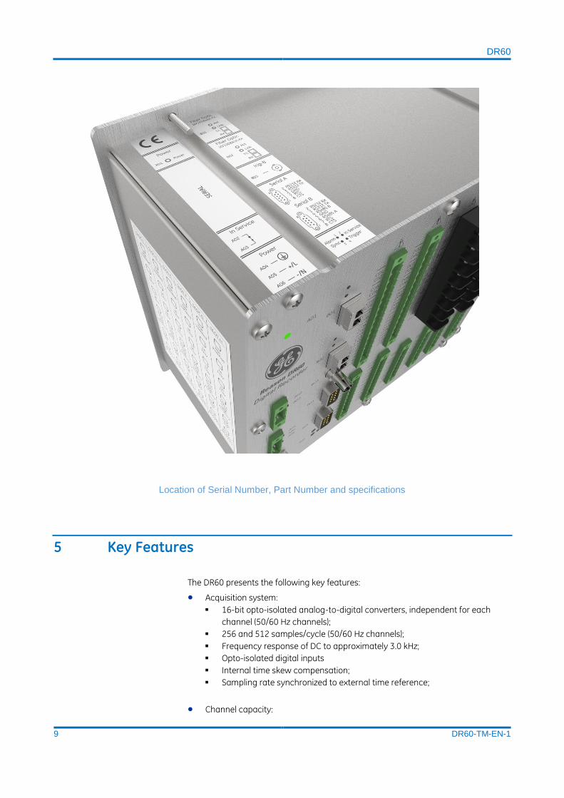
4.1 DR60 Nameplate Information about the company, power supply, the serial number and part number is
shown on a small nameplate affixed to the rear of the equipment, as shown in figure
below.
DR60
9 DR60-TM-EN-1
Location of Serial Number, Part Number and specifications
5 Key Features
The DR60 presents the following key features:
Acquisition system:
16-bit opto-isolated analog-to-digital converters, independent for each
channel (50/60 Hz channels);
256 and 512 samples/cycle (50/60 Hz channels);
Frequency response of DC to approximately 3.0 kHz;
Opto-isolated digital inputs
Internal time skew compensation;
Sampling rate synchronized to external time reference;
Channel capacity:
DR60
10 DR60-TM-EN-1
Up to 16 voltage inputs;
Up to 16 current inputs;
Up to 16 transducer voltage inputs;
Up to 16 transducer current inputs;
Up to 96 digital inputs;
Note: Maximum capacity of channels depends on boards combination
Fan-less and no rotating part design
Waveform recorder at 256 and 512 samples/cycle;
Disturbance and continuous disturbance at 1, 2 or 4 samples/cycle;
IRIGB-004 and IEEE 1588 PTPv2
Trigger using Boolean logic equations;
GOOSE publisher and subscriber (up to 256 GOOSE inputs)
MMS report control block publisher
Cross-trigger using GOOSE messages;
RS232 serial ports for configuration;
1 failsafe contact (normally closed dry contact relay);
6 Compliance The device has undergone a range of extensive testing and certification processes to
ensure and prove compatibility with all target markets. A detailed description of
these criteria can be found in the Technical Specifications chapter.
7 Functional Overview It is a single-box solution design for substation environment and offers a very
flexible combination of boards, which allows the customers to have up to 32 analog
inputs and up to 96 binary inputs. These characteristics along with binary outputs
options and two Ethernet ports, make the DR60 ideal to monitor up to 3 bays
(considering 8 analog and 16 binary inputs per bay).
The DR60 provides a cost-effective solution for disturbance recording through a
distributed approach. It can be installed locally on a per-feeder basis or interconnected
via peer-to-peer GOOSE messaging that allows cross-triggering to occur without the
need to hard-wire the contacts, providing a scalable solution to station-level recording.
The DR60 complements relays by providing independent, high fidelity waveform
capture. It provides Waveform recorders, SOE and triggered and continuous
disturbance recorders - not typically found even in the most advanced digital relays. It
also provides features such GOOSE publisher and subscriber and MMS report control
blocks for integration with supervisory systems.
8 Programs Under the GPL License The DR60 uses GPL licenses in its implementation according to the following table:

DR60
11 DR60-TM-EN-1
PACKAGE LICENSE
glibc GPLv2+ (programs), LGPLv2.1+, BSD-3c, MIT (library)
linux-headers GPLv2
bash GPLv3+
busybox GPLv2
ncurses MIT with advertising clause
readline GPLv3+
e2fsprogs GPLv2, libuuid BSD-3c, libss and libet MIT-like with
advertising clause
util-linux GPLv2+, BSD-4c, libblkid and libmount LGPLv2.1+,
libuuid BSD-3c
zlib zlib license
ethtool GPLv2
gptfdisk GPLv2+
htop GPLv2
irqbalance GPLv2
lighttpd BSD-3c
pcre BSD-3c
mtd GPLv2
mxml LGPLv2+ with exceptions
netsnmp Various BSD-like
openssl OpenSSL or SSLeay
openssh BSD-3c BSD-2c Public Domain
parted GPLv3+
pps-tools GPLv2+
sudo ISC BSD-3c
uboot-tools GPLv2+
vsftpd GPLv2
linux GPLv2
kermit BSD
libiec61850 GPLv3
mms-client GPLv3
ntp-internal ntp license
ptpd-internal BSD

DR60
12 DR60-TM-EN-1

DR60
13 DR60-TM-EN-1
9 Ordering Options
Variants Order Number
1-4 5 6 7-8
9-10
11-12
13-14
15-16
17-18
19-20
21
22-23
24
25
Model Type
DR60 DR60
Slot A - Power Supply
24-48 Vdc 1
100-250 Vdc / 110-240 Vac 3
Slot B - Hardware Options
Processing unit + two RJ45 copper 100BASE-TX Ethernet interfaces E
Processing unit + two multimode LC-type connector 100BASE-X Ethernet interfaces O
Slot C - Binary I/O
16 x 24/48/125/250 V binary inputs
B1
6 x 24/48/125/250 V binary inputs and 8 x binary outputs B2
Not installed
XX
Slot D - Binary I/O
16 x 24/48/125/250 V binary inputs
B1
6 x 24/48/125/250 V binary inputs and 8 x binary outputs B2
Not installed
XX
Slot E - Flexible I/O
16 x 24/48/125/250 V binary inputs
B1
6 x 24/48/125/250 V binary inputs and 8 x binary outputs B2
4 x voltages and 4 x 1/5 A RMS measurement ME
4 x voltages and 4 x 1 A RMS protection
P1
4 x voltages and 4 x 5 A RMS protection
P5
4 x ±10 Vdc and 4 x 0-20 mAdc inputs
DC
Not installed
XX
Slot F - Flexible I/O
16 x 24/48/125/250 V binary inputs
B1
6 x 24/48/125/250 V binary inputs and 8 x binary outputs B2
4 x voltages and 4 x 1/5 A RMS measurement ME
4 x voltages and 4 x 1 A RMS protection
P1
4 x voltages and 4 x 5 A RMS protection
P5
4 x ±10 Vdc and 4 x 0-20 mAdc inputs
DC
Not installed
XX
Slot G - Flexible I/O
16 x 24/48/125/250 V binary inputs
B1

DR60
14 DR60-TM-EN-1
6 x 24/48/125/250 V binary inputs and 8 x binary outputs B2
4 x voltages and 4 x 1/5 A RMS measurement ME
4 x voltages and 4 x 1 A RMS protection
P1
4 x voltages and 4 x 5 A RMS protection
P5
4 x ±10 Vdc and 4 x 0-20 mAdc inputs
DC
Not installed
XX
Slot H - Flexible I/O
16 x 24/48/125/250 V binary inputs
B1
6 x 24/48/125/250 V binary inputs and 8 x binary outputs B2
4 x voltages and 4 x 1/5 A RMS measurement ME
4 x voltages and 4 x 1 A RMS protection
P1
4 x voltages and 4 x 5 A RMS protection
P5
4 x ±10 Vdc and 4 x 0-20 mAdc inputs
DC
Not installed
XX
Primary Functions
Waveform recorder **
Disturbance Recorder **
Continuous Disturbance Recorder **
Secondary Functions
Standard Issue 1
Firmware Version
Latest available firmware - 01 01
Warranty
Standard warranty 0
Hardware Design Suffix
Initial version A
Issue A
DR60
15 DR60-TM-EN-1
DR60
Digital Recorder
Chapter 2: Safety Information
This chapter provides information about the safe handling of the equipment. The
equipment must be properly installed and handled in order to maintain it in a safe
condition and to keep personnel safe at all times. You must be familiar with information
contained in this chapter before unpacking, installing, commissioning, or servicing the
equipment.
1 Health and Safety Personnel associated with the equipment must be familiar with the contents of this
Safety Information.
When electrical equipment is in operation, dangerous voltages are present in certain
parts of the equipment. Improper use of the equipment and failure to observe warning
notices will endanger personnel.
Only qualified personnel may work on or operate the equipment. Qualified personnel
are individuals who are:
familiar with the installation, commissioning, and operation of the
equipment and the system to which it is being connected.
familiar with accepted safety engineering practices and are authorized to
energies and de-energies equipment in the correct manner.
trained in the care and use of safety apparatus in accordance with safety
engineering practices
trained in emergency procedures (first aid).
The documentation provides instructions for installing, commissioning and operating
the equipment. It cannot, however cover all conceivable circumstances. In the event
of questions or problems, do not take any action without proper authorization. Please
contact your local sales office and request the necessary information.
Each product is subjected to routine production testing for Dielectric Strength and Protective Bonding Continuity
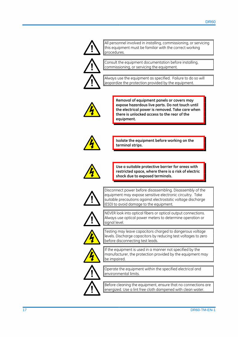
2 Symbols Throughout this manual you will come across the following symbols. You will also
see these symbols on parts of the equipment.

DR60
16 DR60-TM-EN-1
Caution: Refer to equipment documentation. Failure to do so could result in damage to the equipment
Risk of electric shock
Ground terminal. Note: This symbol may also be used for a protective conductor (ground) terminal if that terminal is part of a terminal block or sub-assembly.
Protective conductor (ground) terminal
Chassis functional earth terminal
Both direct and alternating current
Instructions on disposal requirements
The term 'Ground' used in this manual is the direct equivalent of the European term 'Earth'.
3 Installation, Commissioning and Servicing
3.1 Lifting Hazards Many injuries are caused by:
Lifting heavy objects
Lifting things incorrectly
Pushing or pulling heavy objects
Using the same muscles repetitively
Plan carefully, identify any possible hazards and determine how best to move the
product. Look at other ways of moving the load to avoid manual handling. Use the
correct lifting techniques and Personal Protective Equipment (PPE) to reduce the risk
of injury.
3.2 Electrical Hazards
DR60
17 DR60-TM-EN-1
All personnel involved in installing, commissioning, or servicing this equipment must be familiar with the correct working procedures.
Consult the equipment documentation before installing, commissioning, or servicing the equipment.
Always use the equipment as specified. Failure to do so will jeopardize the protection provided by the equipment.
Removal of equipment panels or covers may expose hazardous live parts. Do not touch until the electrical power is removed. Take care when there is unlocked access to the rear of the equipment.
Isolate the equipment before working on the terminal strips.
Use a suitable protective barrier for areas with restricted space, where there is a risk of electric shock due to exposed terminals.
Disconnect power before disassembling. Disassembly of the equipment may expose sensitive electronic circuitry. Take suitable precautions against electrostatic voltage discharge (ESD) to avoid damage to the equipment.
NEVER look into optical fibers or optical output connections. Always use optical power meters to determine operation or signal level.
Testing may leave capacitors charged to dangerous voltage levels. Discharge capacitors by reducing test voltages to zero before disconnecting test leads.
If the equipment is used in a manner not specified by the manufacturer, the protection provided by the equipment may be impaired.
Operate the equipment within the specified electrical and environmental limits.
Before cleaning the equipment, ensure that no connections are energized. Use a lint free cloth dampened with clean water.
DR60
18 DR60-TM-EN-1
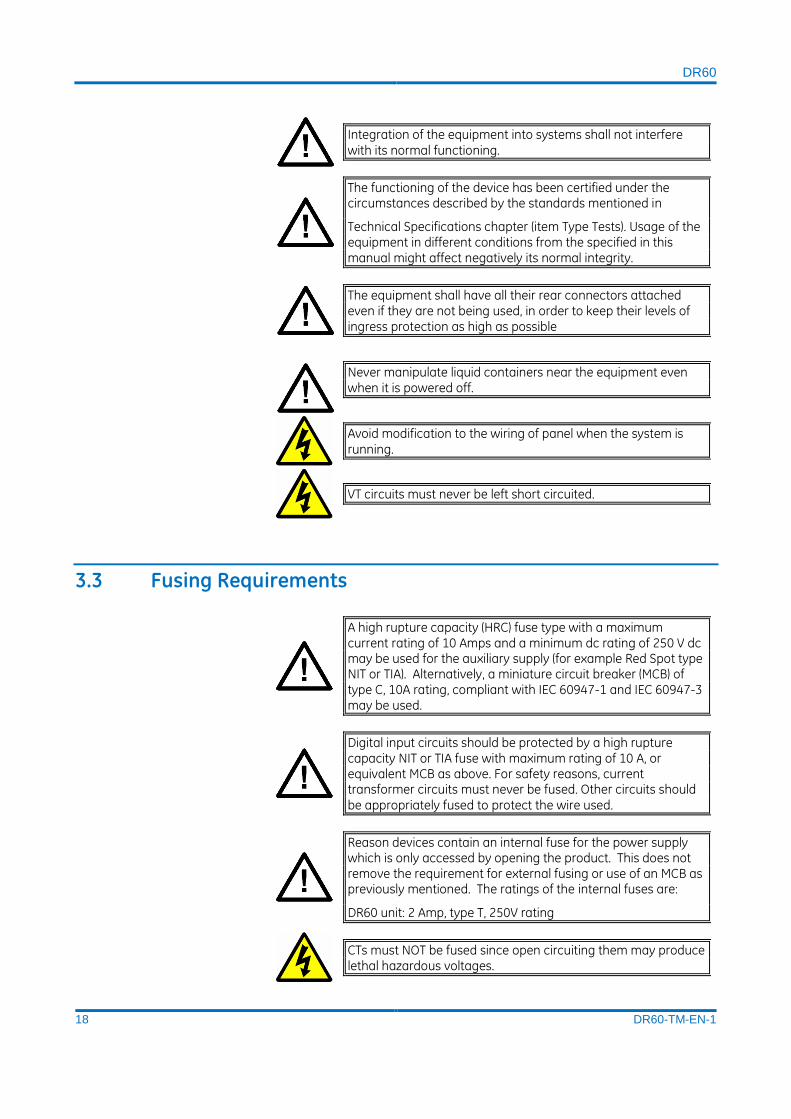
Integration of the equipment into systems shall not interfere with its normal functioning.
The functioning of the device has been certified under the circumstances described by the standards mentioned in
Technical Specifications chapter (item Type Tests). Usage of the equipment in different conditions from the specified in this manual might affect negatively its normal integrity.
The equipment shall have all their rear connectors attached even if they are not being used, in order to keep their levels of ingress protection as high as possible
Never manipulate liquid containers near the equipment even when it is powered off.
Avoid modification to the wiring of panel when the system is running.
VT circuits must never be left short circuited.
3.3 Fusing Requirements
A high rupture capacity (HRC) fuse type with a maximum current rating of 10 Amps and a minimum dc rating of 250 V dc may be used for the auxiliary supply (for example Red Spot type NIT or TIA). Alternatively, a miniature circuit breaker (MCB) of type C, 10A rating, compliant with IEC 60947-1 and IEC 60947-3 may be used.
Digital input circuits should be protected by a high rupture capacity NIT or TIA fuse with maximum rating of 10 A, or equivalent MCB as above. For safety reasons, current transformer circuits must never be fused. Other circuits should be appropriately fused to protect the wire used.
Reason devices contain an internal fuse for the power supply which is only accessed by opening the product. This does not remove the requirement for external fusing or use of an MCB as previously mentioned. The ratings of the internal fuses are:
DR60 unit: 2 Amp, type T, 250V rating
CTs must NOT be fused since open circuiting them may produce lethal hazardous voltages.
DR60
19 DR60-TM-EN-1
3.4 Equipment Connections
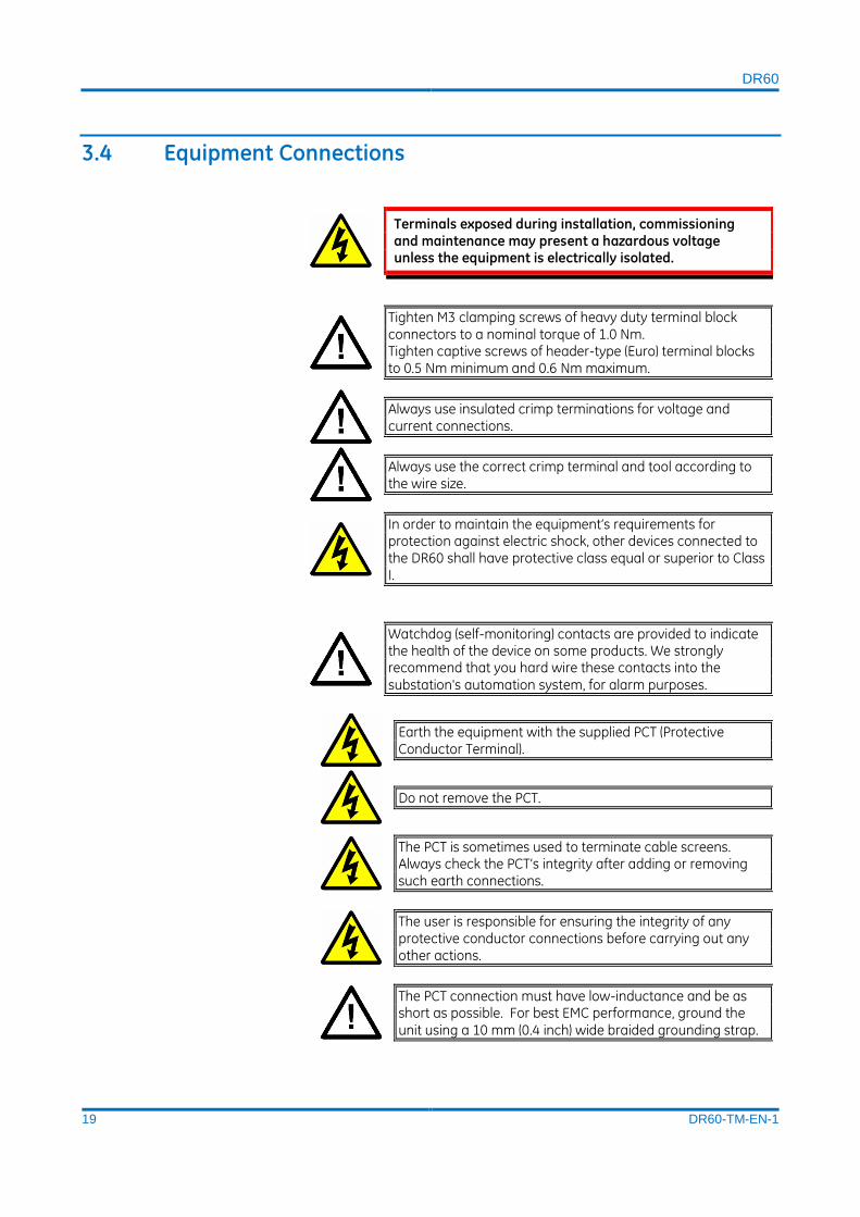
Terminals exposed during installation, commissioning and maintenance may present a hazardous voltage unless the equipment is electrically isolated.
Tighten M3 clamping screws of heavy duty terminal block connectors to a nominal torque of 1.0 Nm. Tighten captive screws of header-type (Euro) terminal blocks to 0.5 Nm minimum and 0.6 Nm maximum.
Always use insulated crimp terminations for voltage and current connections.
Always use the correct crimp terminal and tool according to the wire size.
In order to maintain the equipment’s requirements for protection against electric shock, other devices connected to the DR60 shall have protective class equal or superior to Class I.
Watchdog (self-monitoring) contacts are provided to indicate the health of the device on some products. We strongly recommend that you hard wire these contacts into the substation's automation system, for alarm purposes.
Earth the equipment with the supplied PCT (Protective Conductor Terminal).
Do not remove the PCT.
The PCT is sometimes used to terminate cable screens. Always check the PCT’s integrity after adding or removing such earth connections.
The user is responsible for ensuring the integrity of any protective conductor connections before carrying out any other actions.
The PCT connection must have low-inductance and be as short as possible. For best EMC performance, ground the unit using a 10 mm (0.4 inch) wide braided grounding strap.

DR60
20 DR60-TM-EN-1
All connections to the equipment must have a defined potential. Connections that are pre-wired, but not used, should be earthed, or connected to a common grouped potential.
Pay extra attention to diagrams before wiring the equipment. Always be sure that the connections are correct before energizing the circuits.
3.5 Pre-energization Checklist
Check voltage rating/polarity (rating label/equipment documentation).
Check CT circuit rating (rating label) and integrity of connections.
Check protective fuse or miniature circuit breaker (MCB) rating.
Check integrity of the PCT connection.
Check voltage and current rating of external wiring, ensuring it is appropriate for the application.
3.6 Peripheral Circuitry
Do not open the secondary circuit of a live CT since the high voltage produced may be lethal to personnel and could damage insulation. Short the secondary of the line CT before opening any connections to it.
Reason devices DO NOT feature any automatic CT shorting feature. Therefore, external shorting of the CTs is mandatory. Check the equipment documentation and wiring diagrams carefully.
Where external components such as resistors or voltage dependent resistors (VDRs) are used, these may present a risk of electric shock or burns if touched.

DR60
21 DR60-TM-EN-1
Operation of computers and equipment connected to the DR60 under environmental conditions such as temperature and humidity that exceed the conditions specified in their respective manuals can cause malfunctioning or even irreversible damage to them or the nearby installation.
There might be situations in which the DR60 is operating within its environmental operational range, but the computers, equipment connected to them or nearby equipment are operating outside their operational range. That situation can cause malfunctioning and/or irreversible damage to those devices. In that occasion the communication to the Reason equipment might be compromised but its recording, operational and safety capacities will not be affected.
Take extreme care when using external test blocks and test plugs such as the MMLG, MMLB and P990, as hazardous voltages may be exposed. Ensure that CT shorting links are in place before removing test plugs, to avoid potentially lethal voltages.
3.7 Upgrading/Servicing
Do not insert or withdraw modules, PCBs or expansion boards from the equipment while energized, as this may result in damage to the equipment. Hazardous live voltages would also be exposed, endangering personnel.
Internal modules and assemblies can be heavy and may have sharp edges. Take care when inserting or removing modules into or out of the IED.
4 Decommissioning and Disposal
Before decommissioning, completely isolate the equipment power supplies (both poles of any dc supply). The auxiliary supply input may have capacitors in parallel, which may still be charged. To avoid electric shock, discharge the capacitors using the external terminals before decommissioning.

DR60
22 DR60-TM-EN-1
Avoid incineration or disposal to water courses. Dispose of the equipment in a safe, responsible and environmentally friendly manner, and if applicable, in accordance with country-specific regulations.
5 Standards Compliance Compliance with the European Commission Directive on EMC and LVD is
demonstrated using a Technical File.
5.1 EMC Compliance: Compliance with IEC 60255-26:2013 was used to establish conformity.
5.2 Product Safety Compliance with IEC 60255-27:2014 was used to establish conformity.
Protective Class
IEC 60255-27:2014 Protective Class 1. This equipment requires a protective
conductor (earth) to ensure user safety.
Installation category
When using the 100-250 Vdc / 110-240 Vac power supply: IEC 60255-27:2013
Installation category III (Overvoltage Category III). Equipment in this category is
qualification tested at 5kV peak, 1.2/50 μS, 500 Ohms, 0.5 J, between all supply
circuits and earth and also between independent circuits.
When using the 24-48 Vdc power supply: : IEC 60255-27:2013 Installation
category II (Overvoltage Category II)
Environment
IEC 60068-2-1, IEC 60068-2-2, IEC 60068-2-30, IEC 60068-2-14, IEC 60255-21-1, IEC
60255-21-2. The equipment shall always be installed in a specific cabinet or housing
which will enable it to meet the requirements of IEC 60529 with the classification of
degree of protection IP54 or above.
5.3 R&TTE Compliance Radio and Telecommunications Terminal Equipment (R&TTE) directive 99/5/EC.
Conformity is demonstrated by compliance to both the EMC directive and the Low
Voltage directive, to zero volts.

DR60
23 DR60-TM-EN-1
DR60
Digital Recorder
Chapter 3: Design
This chapter provides information about the hardware design of the products.
1 Hardware Architecture The DR60 is composed of up to 8 boards, from slot A to H. A very flexible number of
inputs and outputs can be achieved by the combination of the boards. The slot A is
reserved for power supply; Slot B for CPU, Ethernet and serial connection and IRIGB
synchronization input; Slots C and D are used for binary input/outputs and slots E to
H can be used either for binary I/O or analog inputs. The figure below illustrates the
DR60 slots composition. For the complete list of board option, refer to the ordering
option in Chapter 1.
DR60 slots composition
2 Mechanical Implementation
Po
we
r Su
pp
ly
CP
U/C
om
mu
nic
atio
n
Dig
ital
Bo
ard
Dig
ital
Bo
ard
An
alo
g o
r D
igit
al
An
alo
g o
r D
igit
al
An
alo
g o
r D
igit
al
An
alo
g o
r D
igit
al
A B C D E F G H
Slots

DR60
24 DR60-TM-EN-1
2.1 DR60 Connections Overview and Indicators
The figure below shows the DR60 front panel with connectors and indicator LEDs.
Front View of the DR60
The diagram and table below show the designation and meaning of each LED.
Power LED
Indicator LEDs
Alarm
In Service
Trigger
Sync
Failsafe relay
Power Supply
Binary I/O Binary I/O or analog inputs
Ethernet interfaces
Serial Interfaces
IRIGB Input

DR60
25 DR60-TM-EN-1
LED Color Indicator Meaning
Alarm
Orange Warning
An alarm event that does not compromise the DR60 functions was detected
Red Alarm
An alarm event that compromised DR60 functions was detected
In Service Green In Service DR60 is working in
perfect conditions
Sync
Green Global
DR60 is synchronized with the time reference clock that is synchronized with satellite reference
Orange Local
DR60 is synchronized with the time reference clock that is not synchronized with satellite reference
Trigger Green Trigger Any trigger occurred
Orange Re-trigger Any trigger reoccurred
The table below shows which events are considered alarms and warnings.
Alarms Description
Card not detected Happens when any board according to the device CORTEC is not detected
Card not compatible Happens when any board is not in accordance with the device CORTEC
Invalid card Happens when any board is not recognized by the device
Record memory full Happens when the memory becomes 98% full
Warnings Description
GOOSE timeout Happens when the time expected for next GOOSE message to come is exceeded
Internal voltage Internal monitored voltages are abnormal
DR60
26 DR60-TM-EN-1
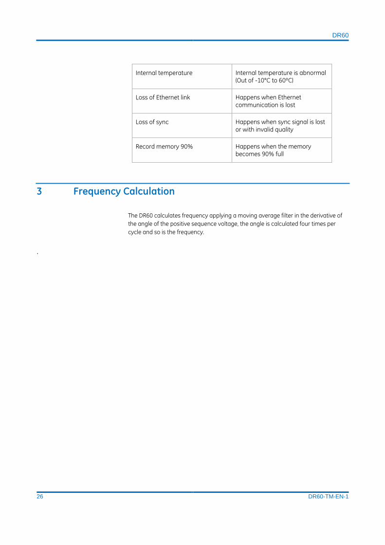
Internal temperature Internal temperature is abnormal (Out of -10°C to 60ºC)
Loss of Ethernet link Happens when Ethernet communication is lost
Loss of sync Happens when sync signal is lost or with invalid quality
Record memory 90% Happens when the memory becomes 90% full
3 Frequency Calculation
The DR60 calculates frequency applying a moving average filter in the derivative of
the angle of the positive sequence voltage, the angle is calculated four times per
cycle and so is the frequency.
.

DR60
27 DR60-TM-EN-1
DR60
Digital Recorder
Chapter 4: Configuration
This chapter includes detailed instructions of how to configure all available features
in the device.
1 DR60 Configurator Tools The DR60 Configurator the is the DR60’s ICT (IED configuration tool). It allows the
modification of all configurable functionalities of the device, including
communication aspects, recorders, binary I/O etc.
1.1 Main Screen The figure below shows the main screen of the DR60 Configurator. This screen is
accessed by opening an existing configuration, reading the device configuration or
creating a new configuration.
The DR60 Configurator is available in the following languages:
- English;
- French;
- Spanish and;
- Portuguese.

DR60
28 DR60-TM-EN-1
DR60 Configurator main screen
Below is described the main common menu options on the screen according to the
highlights on the figure above:
A Menu bar: New Configuration.
B Menu bar: Open Configuration.
C Menu bar: Save Configuration.
D Menu bar: Save Configuration As.
E Menu bar: Receive Configuration: download configuration from the DR60.
F Menu bar: Send Configuration: send configuration to the DR60.
G Menu bar: User: Show which level of user is currently connected (Configuration, Administration).
H Menu bar: Exit
I Configuration tabs: contain all the device configuration divide by categories.
J Configuration sub-tabs: divide a tab the configuration into groups for ease of
configuration
K IP address of the DR60 currently connected to the DR Configurator.
1.2 Configuration Tabs The settings tabs contain all configurable parameters of the equipment divided by
categories. There are seven settings tabs, as shown in the figure below.
DR60 Configurator Settings Tabs
K
A B C D E F G
H
I
JJ

DR60
29 DR60-TM-EN-1
Through the setting tabs it is possible to configure all the equipment parameters, as
detailed on the table below. The possible configurations and the procedure to
configure each parameter will be described in the next sections.
Hover the mouse cursor over the text fields of the configurable parameters to show
the range of values or the possible characters.
The table below describes the menu options:
Tab Sub-tab Description
General Physical Device (LPHD)
Contains the values and parameters of the Physical Device logical node (LPHD), such as: Model, Identifier, Location etc.
Analog Instrument Transformer logical nodes (TCTR/TVTR)
Contains the parameters related to each analog input, such as: system frequency, tag of the channel, primary nominal value, instrument transformer ratios and fine tune compensation of each channel.
Bay Arrangements (MMXU/MMXN)
Configures name tags and associates the analog physical terminals to the measurements circuits; MMXU for three-phase circuits and MMXN for single-phase circuits.
Binary Binary Inputs Configures the voltage level, debouncing time and polarity of the binary inputs.
GOOSE Inputs Enables and configures the tags of the GOOSE inputs
Communication Physical Configures parameters related to the Ethernet and serial ports, such as: PRP redundancy, IP Address etc.
Dataset Adds and edits the datasets to be sent via GOOSE of MMS
GOOSE Publisher Associates the datasets to GOOSE Control Blocks to be published.
GOOSE Subscriber
Configures the GOOSE subscriptions using the SCL files from the IEDs publishing GOOSE.
Reports Associates the datasets to Report Control Blocks to be published.
Synchronization Synchronization Configure the synchronization source/protocol, timezone and daylight saving time parameters.

DR60
30 DR60-TM-EN-1
Recording Recording Configures the parameters of the DR60 recorders (Waveform, disturbance, continuous disturbance and SOE), such as: pre, post time, sampling rate and others.
Thresholds Thresholds (RADR)
Contains the thresholds to trigger the DR60 waveform and disturbance recorder
Equations Allows the creation of logical equations using the DR60 variables (inputs, logical nodes parameters).
Matrix Configures which thresholds, binary/GOOSE inputs or equations will trigger the DR60 recorders. Also, configures the DR60 binary outputs.
1.3 Status Bar Status bar presents the software name, the connection status (if it is connected,
reading or sending configurations), and the Ethernet IP address, as shown in the
figure below.
DR60 Configurator Status Bar
2 Access Levels The DR60 Configurator has three access levels, each one with a corresponding user
name.
The MON user is able access the DR60 Logs;
The CFG user is able to access the DR60 logs, to create, receive and send
configurations and to change its own password.
The ADM user is able to do all that CFG user is able to, plus firmware update, device
key change and alter all users’ passwords.
Password is not required to access the web monitoring page
The user names and default password are presented below:
User Password
CFG 123cfg
ADM 123adm

DR60
31 DR60-TM-EN-1
MON 123mon
3 Communication Setup and Configuration Files Use This section describes how to configure the communications parameters and how to
manipulate configuration files (CID), using the DR60 Configurator.
The initial screen of the DR60 Configurator application is shown in the figure below
and has the following options:
DR60 Configurator initial screen
A <New>: creates a new configuration file.
B <Receive>: receives a configuration file from the DR60 configured in the
Communication menu.
C <Open>: this button opens a file containing a pre-existing configuration.
D <Communication>: this button opens communications parameters for connecting
settings.
E <HMI>: this button opens the window containing information about the device.
F <Administrative Tools>: this button opens the window containing the following
options:
Firmware update;
Key update;
Access control – allows changing the password for each kind of user (CFG,
ADM and MON);
Support file – Downloads a support file containing internal logs used for
diagnosis.
On the initial screen, it is also possible to change the software language by clicking
the icon on the bottom right corner.
DR60
32 DR60-TM-EN-1
3.1 Configuring Communication Parameters The <Communication> button on the initial screen opens the Communication Setup
screen that allows the configuration of the parameters to connect with the DR60. The
DR60 Configurator can communicate with the DR60 using serial RS232/RS485 or
Ethernet interfaces. The serial ports parameters and the IP address of the to be
connectedDR60.
The following option are available on the screen:
Serial:
Ports
Speed
Data Bits
Parity
Stop Bits
Ethernet
IP Address
Name: inserts the identification name of this connection.
Saved Connections: shows the name of the saved connections.
<Add>: this button adds a connection name to the Saved Connections area.
<Remove>: this button removes a selected connection name from the Saved Connections area.
3.1.1 IP Address Scanning
The DR60 Configurator is able to scan the Ethernet network and recover the IP
Addresses of the connected DR60s. This tools is useful when the IP Address of the
DR60 the user wants to communicate is not known.
The IP Address Scanning tool is located on the Communication setup screen.
3.2 Creating a New Configuration File In order to create a new configuration, click on the <New> button on the initial screen
of the DR60 Configurator.
It opens a window to configure the order code of the equipment, according to
hardware configuration.
A Order Code: the order code must be created based on the equipment hardware
configuration. On each field insert the configuration of the respective slot. The order
code of the equipment is displayed on the label affixed on the equipment. For
additional information about the formation of the order code, refer to APPENDIX A.
B <Cancel>: this button cancels the order code edition and goes back to the initial
screen of the DR60 Configurator.

DR60
33 DR60-TM-EN-1
C <Ok>: this button confirms the order code edition and opens the main screen of the
DR60 Configurator.
It is also possible to create a new configuration file through the Main Screen of the
DR60 Configurator, by selecting the option New CID on the File menu.
3.3 Receiving an Equipment Configuration File To receive an online equipment configuration, click on the <Receive> button on the
initial screen of the DR60 Configurator. The configurator will communicate with the IP
Address or serial configuration configured in the Communication Setup screen and
download the DR60 current configuration loading it on the main Screen of the DR60
Configurator.
It is also possible to receive an equipment configuration file from the Main Screen of
the DR60 Configurator, by selecting the option Receive Configuration on the Menu
Bar.
After clicking the Receive button, an authentication window will pop up asking for a
user and a password to complete the operation.
The possible user names and passwords are:
User Password
CFG 123cfg
ADM 123adm
3.4 Opening a Pre-existing Configuration File In order to open a pre-existing configuration, click on the <Open> button on the initial
screen of the DR60 Configurator.
It opens the Windows© folder where the configuration files are saved:
Choose the configuration file and the Main Screen of the DR60 Configurator will open,
with the selected configuration file loaded.
It is also possible to open a configuration file from the Main Screen of the DR60
Configurator, by selecting the option Open Configuration on the menu on the Menu
Bar.
3.5 Saving a Configuration File To save an opened configuration, select the option Save Configuration or Save
Configuration As, on the File menu of the Main Screen of the DR60 Configurator.
When saving a configuration, the DR60 Configurator will create three different files:
*.CID file: saves the communication and recorders configuration. The DR60 uses the
SCL schema 3.1 from the IEC 61850 data models;
*.st file: saves the logic equation and the matrix of I/O and triggering configuration
according to the IEC 61131 Structured Text Language (STL).

DR60
34 DR60-TM-EN-1
*extref: saves the external references for the GOOSE subscriber configuration.
3.6 Sending a Configuration File for the Equipment To send a configuration file to online equipment, select the option Send
Configuration, on the Menu Bar.
4 Tools The Tools section of the Initial screen presents two different tools:
Log: monitored and downloads the DR60 logs
Administrative Tools: Firmware upgrade, password management, equipment license
upgrade and support file download.
Upon clicking the menus, an authentication window will pop up asking for a user and
a password to complete the operation
The possible user names and passwords are:
User Password
CFG 123cfg
ADM 123adm
MON 123mon
The tools menus are described in the next sections.
4.1 LOG The equipment maintains a history of the last 10000 system events that can be
downloaded in from the DR60. The logs visualization screen can show up to 2000
events.
The option on the Log screen are described below:
A IED Name: indicates IED Name.
B IP Address: indicates IP of the device that the software is connected to.
C Period: chooses the period of time to be displayed, from oldest to most recent.
D Codes: searches specific logs or time intervals. For example, search a log between
300 and 399, just enter 3??, and to search a list, enter 2??, 507, 700. Codes shall be
entered with 3 digits.
E <Refresh>: this button shows the list of logs according to the filtering parameters.
F <Download>: this button downloads the log files to the folder.

DR60
35 DR60-TM-EN-1
G Time stamp: indicates the date and time of event log (yyyymm-dd
hh:mm:ss[.uuuuuu] ± 0000 (UTC time offset).
H Code: indicates the log code.
I Description: describes the log.
4.2 Administrative Tools
This menu allows the user to perform the following configurations:
Access Control – allows changing the password for each kind of user (CFG,
ADM and MON);
Firmware Update;
License Update;
Support File – Downloads a support file containing internal logs used for
diagnosis.
5 Configuration Tabs
5.1 General The General configuration tab contains information related to the physical device
logical node (LPHD) of the DR60.
On this screen, it is shown the information of the respective device:
Model (CORTEC)
Vendor (General Electric Company)
Hardware Version
Firmware Version
Serial Number
Moreover, the following parameter can be configured:
Identifier: Up to 61 characters. Possible characters: a-z, A-Z, a-9, _.
Location: Up to 255 characters. Possible characters: a-z, A-Z, a-9, _.
Owner: Up to 255 characters. Possible characters: a-z, A-Z, a-9, _.
LPHD Prefix: Up to 11 characters. Possible characters: a-z, A-Z, a-9, _.
Electric Power System: Up to 255 characters. Possible characters: a-z, A-Z,
a-9, _.
Primary Operator: Up to 255 characters. Possible characters: a-z, A-Z, a-9, _.
Secondary Operator: Up to 255 characters. Possible characters: a-z, A-Z, a-
9, _.
Master Resource Identification: Up to 255 characters. Possible characters: a-
z, A-Z, a-9, _.
Latitude: Possible characters: 0.0-90.0.
Longitude: Possible characters: 0.0-180.0.
Altitude: Possible characters: 0.0-10000.0
DR60
36 DR60-TM-EN-1
5.2 Analog The Analog configuration tab contains configurations related to the analog channels
and circuits and it is divided into two sub-tabs: Instrument Transformer (TCTR/TVTR);
and Bay Arrangement (MMXU/MMXN).
5.2.1 Instrument Transformer (TCTR/TVTR)
This sub-tab contains the configuration related to the analog channels. The following
configurations are available:
Nominal Frequency: 50 Hz or 60 Hz.
Inputs: Enable or disable each analog input.
Name: Enter name tags for each analog input. Maximum characters: 10.
Possible characters: a-z, A-Z, a-9, _.
Nominal Value (LL): Set the nominal primary values of the CTs and VTs.
Ratio: Configure the CTs and VTs ratio for each analog input. For example: a
CT with primary value 1000A and secondary 5A has a ratio equal to 200
(1000/5).
Compensation: Inserts a percentage value onto the DR60 reading of that
specific analog inputs. Possible characters: -100.0% to 100.0%.
𝐶𝑜𝑚𝑝𝑒𝑛𝑠𝑎𝑡𝑖𝑜𝑛 = (𝐴𝑝𝑝𝑙𝑖𝑒𝑑 𝑉𝑎𝑙𝑢𝑒
𝑅𝑒𝑎𝑑 𝑉𝑎𝑙𝑢𝑒− 1) ∗ 100%
For example:
Applied value: 100 V.
Read value: 99 V.
𝐶𝑜𝑚𝑝𝑒𝑛𝑠𝑎𝑡𝑖𝑜𝑛 = (100
99− 1) ∗ 100% = 1,01%
5.2.2 Generic Sensor (TGSN) – Transducer inputs
This subtab configures the transducer inputs.
The signal of the transducer (±10 V or 0-20 mA) is converted in to the desired physical
measurement using a first order transfer function with the parameters of gain (𝐴)
and offset (𝐵) defined by the user:
𝑦 = 𝐴(𝑥 + 𝐵)
where 𝑦 is the converted value and 𝑥 is the value read by the DC channel in Volts or
Amps.
DR60
37 DR60-TM-EN-1
The screen allows the user to configure for each channel: a name, the Gain A, the
Offset B and the Unit of the measurement that the transducer represents.
5.2.3 Bay Arrangement (MMXU/MMXN)
This screens allows the configuration of the three-phase circuits (MMXU) and single-
phase circuits (MMXN). The configuration includes the association of the analog
physical inputs (TVTR/TCTR) to the virtual MMXU/MMXN circuits.
The following configurations are available:
Current and Voltage circuits:
Type: Chooses if the circuit is
- Complete: logical node with current and voltage inputs;
- Current: logical node with only current and no voltage inputs; or
- Voltage: logical node with only voltage and no current inputs
Name: Configures the name tag of the corresponding circuit. Maximum
characters: 10. Possible characters: a-z, A-Z, a-9, _.
Logical Node: shows the logical node of the corresponding circuit.
Wiring Type (I): Selects whether the current circuit is:
- Star 3-phase: circuits comprised of 3 or 4 inputs or;
- Single_Phase: circuits comprised of 1 input.
Wiring Type (V): Selects whether the voltage circuit is:
- Star 3-phase: circuits comprised of 3 or 4 inputs or;
- Single_Phase: circuits comprised of 1 input.
Ia/Iab: Chooses the analog physical input (TCTR1…TCTRn) corresponding to
the current phase A; or the “Synthetized” option, which will calculate the
corresponding phase according to the signals of the remaining phases.
Ic/Ibc: Chooses the analog physical input (TCTR1…TCTRn) corresponding to
the current phase B; or the “Synthetized” option, which will calculate the
corresponding phase according to the signals of the remaining phases.
Ic/Ica: Chooses the analog physical input (TCTR1…TCTRn) corresponding to
the current phase C; or the “Synthetized” option, which will calculate the
corresponding phase according to the signals of the remaining phases.
In: Chooses the analog physical input (TCTR1…TCTRn) corresponding to the
neutral current; or the “Synthetized” option, which will calculate the
corresponding phase according to the signals of the remaining phases.
Va/Vab: Chooses the analog physical input (TCTR1…TCTRn) corresponding to
the voltage phase A; or the “Synthetized” option, which will calculate the
corresponding phase according to the signals of the remaining phases.
Vc/Vbc: Chooses the analog physical input (TCTR1…TCTRn) corresponding to
the voltage phase B; or the “Synthetized” option, which will calculate the
corresponding phase according to the signals of the remaining phases.
Vc/Vca: Chooses the analog physical input (TCTR1…TCTRn) corresponding to
the voltage phase C; or the “Synthetized” option, which will calculate the
corresponding phase according to the signals of the remaining phases.
Vn: Chooses the analog physical input (TCTR1…TCTRn) corresponding to the
neutral voltage; or the “Synthetized” option, which will calculate the

DR60
38 DR60-TM-EN-1
Frequency Reference: Chooses the reference frequency for each circuit.
Current circuit can use any voltage circuit as reference or the nominal
frequency value.
Power circuits: configures the power circuits using the current and voltage circuits
previously configured.
Name: Configures the name tag of the corresponding circuit. Maximum
characters: 10. Possible characters: a-z, A-Z, a-9, _.
Logical Node: shows the logical node of the corresponding circuit.
Current Source: chooses the current circuit used to calculate power in the
corresponding power circuit.
Voltage Source chooses the voltage circuit used to calculate power in the
corresponding power circuit.
A To add a new circuit, click the + sign on the left side of the screen.
B To remove a circuit, select the line of the circuit to be deleted by clicking any of the
parameters of the corresponding circuit and then hit Delete on the computer
keyboard.
Figure below shows the two point above mentioned.
5.3 Binary This configuration tab contains the parameters to configure the physical binary
inputs, enable/disable GOOSE inputs and set their name tags.
5.3.1 Binary Inputs Subtab
The following aspects related to the physical binary inputs are configured on this
subtab:
A
B

DR60
39 DR60-TM-EN-1
Level: Selects the voltage level of the binary inputs. There are two options
available: 24/48Vdc and 125/250Vdc. The operating changes of each level is
shown in the Technical Specification Chapter. Applying voltage signals
incompatible to the Level configuration may damage the inputs.
GGIO_DIGITAL: Shows the index reference of each binary input (Ind1…Indn).
Name: Configures the name tags of each binary input. Maximum
characters: 12. Possible characters: a-z, A-Z, a-9, _.
Debouncing Time: The DR60 will only start a record once the binary
activation time (i.e. duration of the HIGH signal for the normal polatiry
channels) has exceeded the debouncing time parameter.
Polarity: chooses the polarity of each input.
- Normal: LOW signals are interpreted as LOW signals and HIGH signals
are interpreted as HIGH signals.
- Inverted: HIGH signals are interpreted as LOW signals and LOW signals
are interpreted as HIGH signals.
Choose the voltage level of the binary inputs accordingly to the voltage levels applied to them. Choosing 24/48V voltage level and applying higher voltage levels can damage the inputs.
5.3.2 GOOSE Inputs
This subtab allows enabling/disabling and entering a name tag for each GOOSE
input.
The DR60 can handle up to 256 GOOSE inputs to record, cross-trigger and trigger
recorders.
The following parameters are available for configuration:
GGIO_GOOSE: Enables or disables the corresponding GOOSE input.
Name: Configures the name tags of each binary input. Maximum
characters: 12. Possible characters: a-z, A-Z, a-9, _.
5.4 Communication This configuration tab contains all the configuration related to communication to
other devices, such as: Ethernet and serial ports, GOOSE and Report control blocks
and GOOSE subscriber.
5.4.1 Physical
The configuration of the physical communication ports is carried out though this
subtab.
Each Ethernet port, 1 and 2, have different addresses and it is possible to configure
for each of them:
DR60
40 DR60-TM-EN-1
IP Address
Network Mask
Gateway
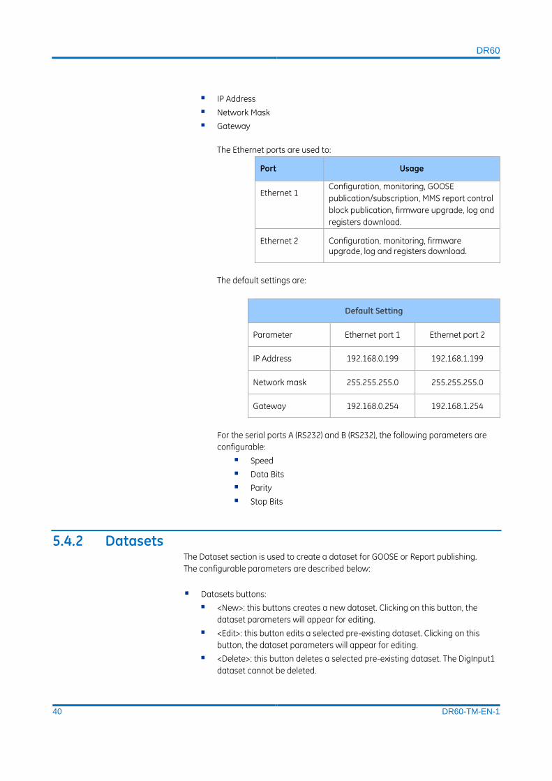
The Ethernet ports are used to:
Port Usage
Ethernet 1 Configuration, monitoring, GOOSE
publication/subscription, MMS report control
block publication, firmware upgrade, log and
registers download.
Ethernet 2 Configuration, monitoring, firmware upgrade, log and registers download.
The default settings are:
Default Setting
Parameter Ethernet port 1 Ethernet port 2
IP Address 192.168.0.199 192.168.1.199
Network mask 255.255.255.0 255.255.255.0
Gateway 192.168.0.254 192.168.1.254
For the serial ports A (RS232) and B (RS232), the following parameters are
configurable:
Speed
Data Bits
Parity
Stop Bits
5.4.2 Datasets The Dataset section is used to create a dataset for GOOSE or Report publishing.
The configurable parameters are described below:
Datasets buttons:
<New>: this buttons creates a new dataset. Clicking on this button, the
dataset parameters will appear for editing.
<Edit>: this button edits a selected pre-existing dataset. Clicking on this
button, the dataset parameters will appear for editing.
<Delete>: this button deletes a selected pre-existing dataset. The DigInput1
dataset cannot be deleted.

DR60
41 DR60-TM-EN-1
Functional Constraint: selects the functional constraint that indicates the
possible operating services of a specific DataAttribute. The functional
constraints are:
ST: Status Information;
MX: Measurements;
CO: Control;
SP: Setting Point;
SG: Setting Group;
SE: Setting Group Editable
SV: Substitution
CF: Configuration
DC: Description
EX: Extended Definition
Dataset Name: inserts a name for the new dataset. Maximum characters: 32.
Possible characters: a-z, A-Z, a-9, _.
Description: inserts a description for the new dataset. Maximum characters: 64.
Possible characters: except “<” and “>”.
Filter: enables the user to filter the global dataset by DataAttribute names.
Note:
When selecting the data for the dataset, the IEC 61850 name for binary inputs is
DIGITALGGIO and the binary outputs as OUTPUTGGIO.
5.4.3 GOOSE Publisher To publish GOOSE messages grouped in datasets, it is necessary to create a GOOSE
Control Block (GCB). In the GOOSE Publisher subtab it is possible to create and edit
GOOSE Control Blocks for the GOOSE messages transmission.
Each GCB is associated with one Dataset and the DR60 is able to send up to 16 GCB.
The configurable parameters are described below:
GOOSE Control Block Identification
Message Name: inserts a name for the GOOSE Control Block. The allowed
characters are 0-9, a-z, A-Z and ‘_’. Maximum characters: 32.
Description: inserts a description for the GOOSE Control Block. The not
allowed characters are ‘<’ and ‘>’. Maximum characters: 64.
GOOSE ID: inserts an identification for the GOOSE Control Block. The allowed
characters are 0-9, a-z, A-Z and ‘_’. Maximum characters: 129.
Dataset: selects the dataset for this GOOSE Control Block. In this field will
appear all created datasets.
Network Settings
APP ID: inserts an indication of the message identifier. The identifier must
contain four hexadecimal characters. Characters range 0x0 – 0x3FFF.

DR60
42 DR60-TM-EN-1
MAC-Address: inserts an indication of the MAC address of the originator to
be filtered. The address must be represented as six groups of hexadecimal
characters. The allowed characters are 0-9, a-f, A-F and ‘-‘.’. IEC 61850-8-1
standard recommends the MAC address for GOOSE messages creation as
following:
The first three bytes are 01-0C-CD;
The fourth byte must be 01 for GOOSE;
Thus, the MAC address must be from 01-0C-CD-01-00-00 to 01-0C-CD-
01-01-FF.
VLAN-PRIORITY: selects the VLAN priority. Such priority must be a numeric value
between 0 and 7.
VLAN-ID: inserts the VLAN unique identification. Characters range 0x0 – 0xFFF.
Minimum Time: inserts the maximum delay time allowed for message
transmission, after the change of the state. The range is from 1 ms to 60000 ms.
Maximum Time: inserts the source supervision time. If there is none change of
state, a message is transmitted in this time. The range is from 4 ms to 60000 ms.
5.4.4 GOOSE Subscriber
The DR60 has 256 virtual GOOSE inputs that can be associated with GOOSE Booleans
values.
The configurable parameters are described below:
To associate a GOOSE Control Block with a digital input, do the following:
1 Load the SCL file from the IED sending the messages clicking “Add SCL File”.
2 On the right side, select the GOOSE Boolean that the DR60 shall subscribe to, on the
right side select the GOOSE input that will be associated with that GOOSE boolean.
Only the GOOSE inputs enabled in the Binary configuration tab will be displayed.
3 Click the “>>” button to perform the association and “<<” to undo it.
5.4.5 Reports This screen allows the user to configure the MMS Report Control Blocks (RCB). The
Report Control Block sends internal variables grouped on a datasheet to the
supervisory system.
Each RCB is associated to one Dataset and the DR60 is able to send up to 15
buffered or unbuffered Report Control Blocks.
The configurable parameters are described below:
Report Control Block Identification and data
Message Name: inserts a name for the GOOSE Control Block. The allowed
characters are 0-9, a-z, A-Z and ‘_’. Max characters: 32.

DR60
43 DR60-TM-EN-1
Description: inserts a description for the GOOSE Control Block. The not
allowed characters are ‘<’ and ‘>’. Max characters: 64.
Report ID: Optional RCB identifier. The allowed characters are 0-9, a-z, A-Z
and ‘_’. Max characters: 74.
Dataset: selects the dataset for this Report Control Block. All the created
datasets will be listed here.
Options
Buffered: internal events (caused by trigger options data-change, quality-
change, and data-update) issue immediate sending of reports or buffer the
events (to some practical limit) for transmission, such that values of data
object are not lost due to transport flow control constraints or loss of
connection.
Buffered Time: specifies the time interval in milliseconds for the buffering of
internal notifications caused by data-change (dchg), quality-change (qchg),
dataupdate (dupd) by the BRCB for inclusion into a single report.
Upon receipt of the first set of internal notification of events of the
referenced data-set, the BRCB starts a timer of the duration buffer time.
When the timer expires, the BRCB combines all internal notifications that
have been received during the time interval into a single report. The next
internal notification following the timer expiration signals the new start of
that timer. Range: 1 – 1000 ms. Step 1 ms;
Indexed: When checked the report control block instance names are
created from the RCB name, followed by an index number from 01 up to
maximum 99.
Max Instances: To allow multiple clients to receive the same values of data
object, multiple instances of the report control classes shall be made
available. Once a report control block is reserved, by a specific client, no
other client shall have access rights to set the control block attributes. Up to
16 instances can be configured.
Trigger Options: Specifies the trigger conditions which will be monitored by this
BRCB. The following values are defined:
Data Change(dchg); relates to a change in a value of a DataAttribute
representing the process-related value of the data object
Quality Change(qchg); relates to a change in the quality value of a
DataAttribute.
Data Update (dupd): relates to a freeze event in a value of a DataAttribute
representing a freeze value of the data object (for example, frozen counters)
or to an event triggered by updating the value of a DataAttribute. Data-
update trigger condition may be used to issue sending a report or storing a
log entry into a log when a value of a DataAttribute has updated. Updating
may mean that the value has changed or has been “overwritten” with the
same value as before. The dupd trigger condition can be used as a trigger
for statistics values that may be calculated and updated on a periodic base.
Independently of whether the statistics value has changed or not, the value
will be reported or logged.
General Interrogation: After a request for General Interrogation the BRCB
starts the interrogation process and create a report that includes all
DataAttribute values of the referenced dataset.
DR60
44 DR60-TM-EN-1
Integrity: When integrity reports are enabled, the BRCB shall be notified
each time the value of the time as specified in Integrity Period has expired.
The BRCB then builds a report with the values of all members of the
referenced data-set. Range: 1 – 1000 ms. Step 1 ms.
Note: The general-interrogation is initiated by the client. The integrity report, which also transmits all values of a data set, is initiated by the BRCB.
Optional Fields:
Sequence Number: Includes the SqNum in the report. The attribute SqNum
specifies the sequence number for each BRCB that has report enable set to
TRUE. This number is incremented by the BRCB for each report generated
and sent.
Dataset: Includes DatSets in the report
Data Reference: Includes the DataRef in the report
Buffer Overflow: Includes the BufOvfls in the report. The parameter BufOvfl
indicates to the client that entries within the buffer may have been lost.
Time Stamp: Includes the time stamp in the report.
Reason Code: Includes the Reason Codes in the report, which means the
reason that generated the report according to Trigger Options
Entry ID: Includes EntryID in the report.
Configuration Revision: Includes the ConfRev in the report. The attribute
ConfRevshall represent a count of the number of times that the
configuration of the data-set referenced by DatSet has been changed.
Note: RMS values and frequency values are calculated and made available for MMS communication every ¼ cycle.
5.5 Synchronization
5.5.1 Synchronization
The DR60 supports time synchronization with PTP IEEE1588v2 and demodulated
IRIGB-004. It is also possible to configure the DR60 to work with no time sync, just
with the internal clock.
The following parameters are found on this configuration sab:
Time source:
IRIGB: sets the DR60 to be synchronized with IRIGB. No further configuration is
necessary.

DR60
45 DR60-TM-EN-1
PTP: sets the DR60 to be synchronized with PTPv2. The PTP configuration
presents the following parameters:
5.5.1.1 PTP Configuration
The PTPv2 synchronization source presents the following parameters:
Holdover Time: Period during which the DR60 can maintain the
synchronization quality without an external sync reference, thanks to drift of
the internal clock. Range: 5 – 60s.
Network Interface: Choses the Ethernet port used for the PTP sync.
Profile: Choses between the PTP profiles: Power IEEE C37.238/2011, P2P
default and Custom.
Domain Number: A PTP domain is a collection of one or more PTP
subdomains. A subdomain is a logical grouping of 1588 clocks that
synchronize to each other using the PTP protocol, but that are not
necessarily synchronized to PTP clocks in another PTP subdomain.
Subdomains provide a way of implementing disjoint sets of clocks, sharing a
common network, but maintaining independent synchronization within
each set. The domain number can be set as 0, 1, 2 or 3.
Network Protocol: allows the user to choose between the UDP protocol and
Ethernet layer 2.
VLAN ID and Priority: Define VLAN parameters according to IEEE 802.1Q.
Operation Mode: Two options are available:
Two-step: In two-step-mode the master sends a synchronization
message – SYNC message – with an estimated value of the time
cyclically to the connected slaves. Parallel to this, the time at
which the message leaves the sender is measured as precisely as
possible. The master then sends this actual exact transmission
time of the corresponding sync message to the slaves in a
second message - follow-up message. These also measure the
reception time of these messages as exactly as possible and can
correct the correction value (offset) to the master from it. The
slave clock is then corrected by this offset. If the transmission line
were to have no delay, both clocks would be synchronized.
One-step: The master sends a synchronization message – SYNC –
message with the precise value of the time cyclically to the
connected slave. Other than in two-step-mode, the precise time
is inserted into the SYNC message “on-the-fly” by the hardware.
No FOLLOWUP – messages are needed in this mode. The
calculation of the offset is the same as in two-step-mode..
Delay Mechanism: Two delay mechanism are defined:
End-to-end: Only measures the time taken for a PTP event
message to transit the bridge and provide this information to the
receiving clocks in the correction field of the PTP message. In this
mode the propagation delay of the link connected to the port is
not corrected
DR60
46 DR60-TM-EN-1
Peer-to-peer: Use the peer delay mechanism for the delay
measurement. In addition to providing PTP event transit time
information, also provides corrections for the propagation delay
of the link connected to the port receiving the PTP event message
The peer delay mechanism measures the port to port
propagation delay time between two directly connected ports
sharing the same communication technology.
Grandmaster Priority: Is an administratively assigned precedence hint used
by the Best Master Clock algorithm (BMC) to help select a grandmaster for
the PTP domain. The range is from 0 to 255.
Announce Receipt Timeout: configures the interval between PTP announce
messages on an interface or the number of PTP intervals before a timeout
occurs on an interface.
When configuring PTP, the first point is to select which PTP profile, or which common
parameters, will be used along with all PTP devices. The DR60 has three options to be
selected as profile:
Power Profile – IEEE C37.238/2011: this profile has some fixed parameters
defined by the standard and some configurable parameters defined by the user.
The configurable parameters for Power Profile are:
Domain number;
VLAN ID and Priority;
The fixed parameters are:
Network Protocol: Ethernet Level 2;
Operation Mode: One step;
Delay Mechanism: Peer-to-peer;
Grandmaster Priority: #1 255; #2 255;
Announce Receipt Timeout: 3
The CUSTOM profile has all its parameters opened for user configuration.
The P2P Default profile is partially configurable. The fixed parameters are are:
Domain number: 0;
Grandmaster Priority: #1 128; #2 128
Configurable parameters are:
Domain number:
Operation mode:
Delay Mechanism:
GRANDMASTER PRIORITY:
Announce Receipt Timeout:
Internal clock: sets the DR60 to work with no external source of sync. The
internal clock configuration is carried out through the web interface described in
the Monitoring Web Interface section.

DR60
47 DR60-TM-EN-1
5.5.2 Ethernet Network Synchronism Recommendations
In order to obtain the best synchronism performance in an Ethernet network, the
following configuration is recommended.
PTP Power Profile (IEEE C37.238);
o Delay mechanism: Peer-to-Peer ( P2P)
This means that ALL equipment (Switches, GPS clocks, DR60s, Relays, Bay Controllers, and so on) must be PTP-aware.
o Mapped as Ethernet ( Layer 2 – L2) messages
This means that ALL equipment (Switches, DR60s, Relays, Bay Controllers, and so on) must be PTP-aware.
o One-step (preferred) or Two-step operation
Time is stamped preferentially at hardware.
Max number of hops: 16
Max error introduced by hop: 50ns
Max error in slave: 1us
Multicast filtering or VLAN segregation shall be configured in the managed switches, otherwise the DR60 might present instable and undesirable behavior in its applications and synchronism.
5.6 Recording This configuration tab options to enables/disables the waveform, disturbance,
continuous disturbance and SOE recorder and their parameters.
The following configuration parameters are available:
Waveform recorder: Enables/disables the recorder.
Pre trigger time: configures the recording time duration before the
waveform recorder trigger.
Post trigger time: configures the recording time duration after threshold is
desensitized.
Maximum time: configures the maximum time of the record.
Disable for: disables temporarily the recorder if various triggers repeat
within a period of time.
Sample rate: selects the sampling rate of the recorder (256 or 512 s/c).
Retrigger: Enables and disables the retrigger. Refer to Records Chapter for
information on retrigger functioning.
Disturbance recorder: Enables/disables the recorder.
Pre trigger time: configures the recording time duration before the
disturbance recorder trigger.
Post trigger time: configures the recording time duration after threshold is
desensitized.
Maximum time: configures the maximum time of the record.

DR60
48 DR60-TM-EN-1
Disable for: disables temporarily the recorder if various triggers repeat
within a period of time.
Sample rate: selects the sampling rate of the recorder (1, 2 or 4 s/c).
Select Measures: selects which measurement values will be recorded. Up to
128 measurements can be recorded. The full list of measurements is found
in Chapter Records.
Retrigger: Enables and disables the retrigger. Refer to Records Chapter for
information on retrigger functioning.
The ranges and steps for the pre, post and maximum times configuration are shown
in the Records Chapter.
Continuous Disturbance Recorder: Enables/disables the recorder.
Aggregation Period: Configures the duration of each record. A new record
will be created every time the aggregation period elapses. Range: 10.0 to
60.0 minutes.
Sample rate: selects the sampling rate of the recorder (1, 2 or 4 s/c).
Select Measures: selects which measurement values will be recorded. Up to
128 measurements can be recorded. The full list of measurements is found
in Chapter Records.
SOE Recorder: Enables/disables the recorder.
Aggregation Period: Configures the duration of each record. A new record
will be created every time the aggregation period elapses. Range: 1 to 1440
minutes.
5.7 Triggering
The Triggering configuration tab allows the configuration of the parameters used as
thresholds to trigger the waveform and disturbance recorders.
5.7.1 Thresholds This screen allows the configuration of thresholds associated with measured and
calculated values (from the analog channels) that once exceeded can cause the
DR60 recorders trigger.
Following parameters can be set for each defined threshold:
Parameters set for each defined threshold
Parameter Range Step
Hysteresis 0 … 20 % 0.1 %
Hold time 0 … 1000 ms 1 ms

DR60
49 DR60-TM-EN-1
The thresholds are displayed side by side to easy and quick configuration. Upper and
lower thresholds are represented by the following signs:
Threshold Sign Example
Upper (Over)
Over Frequency – F (Hz)
Lower (Under)
Under Frequency – F (Hz)
Blank threshold will not be processed and will not trigger the recorder.
Below is the list of all possible thresholds:
Basic Measures Description Type
V1 (PU) Positive sequence voltage and
V2 (PU) Negative sequence voltage and
V0 (PU) Zero sequence voltage and
I1 (kA) Positive sequence current and
I2 (kA) Negative sequence current and
I0 (kA) Zero sequence current and
THDVP (%) Phase voltage total harmonic distortion and
THDVN (%) Neutral voltage total harmonic distortion and
THDIP (%) Phase current total harmonic distortion and
TDHIN (%) Neutral current total harmonic distortion and
Derivative Measures Description Type
P3θ (MW/s) Total active power
Q3θ (MVAr/s) Total reactive power
S3θ (MVA/s) Total apparent power
F (Hz/s) Frequency
VP (PU/s) Phase voltages RMS
VN (PU/s) Neutral voltages RMS
Fundamental Measures Description Type
P3θ (MW) Total active power and
Q3θ (MVAr) Total reactive power and
S3θ (MVA) Total apparent power and
F (Hz) Frequency and
VP (PU) Phase voltages RMS and
VN (PU) Neutral voltages RMS and
IP (kA) Phase currents RMS and
IN (kA) Neutral currents RMS and
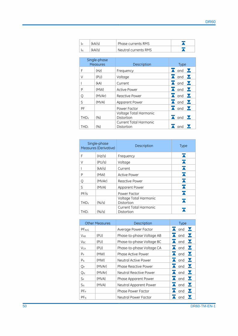
DR60
50 DR60-TM-EN-1
IP (kA/s) Phase currents RMS
IN (kA/s) Neutral currents RMS
Single-phase Measures Description Type
F (Hz) Frequency and
V (PU) Voltage and
I (kA) Current and
P (MW) Active Power and
Q (MVAr) Reactive Power and
S (MVA) Apparent Power and
PF Power Factor and
THDV (%) Voltage Total Harmonic Distortion and
THDI (%) Current Total Harmonic Distortion and
Single-phase Measures (Derivative)
Description Type
F (Hz/s) Frequency
V (PU/s) Voltage
I (kA/s) Current
P (MW) Active Power
Q (MVAr) Reactive Power
S (MVA) Apparent Power
PF/s Power Factor
THDV (%/s) Voltage Total Harmonic Distortion
THDI (%/s) Current Total Harmonic Distortion
Other Measures Description Type
PFAVG Average Power Factor and
VAB (PU) Phase-to-phase Voltage AB and
VBC (PU) Phase-to-phase Voltage BC and
VCA (PU) Phase-to-phase Voltage CA and
PP (MW) Phase Active Power and
PN (MW) Neutral Active Power and
QP (MVAr) Phase Reactive Power and
QN (MVAr) Neutral Reactive Power and
SP (MVA) Phase Apparent Power and
SN (MVA) Neutral Apparent Power and
PFP Phase Power Factor and
PFN Neutral Power Factor and

DR60
51 DR60-TM-EN-1
VPP (PU) Phase Voltages Phasor and
VPN (PU) Neutral Voltages Phasor and
IPP (kA) Phase Currents Phasor and
IPN (kA) Neutral Currents Phasor and
Note: The derivative thresholds are calculated within a windows of 1 cycle.
Description of the Threshold subtab shown in the figure below.
A To add a new Threshold, click the + sign on the left side of the screen.
B To remove a threshold line, select the line by clicking any of the parameters of the
corresponding circuit and then hit Delete on the computer keyboard.
Figure below shows the two point above mentioned.
5.7.2 Equations
This subtab allows the configuration of logic equation using thresholds, binary inputs,
GOOSE inputs and other equations as operands.
The list below shows the logic operator and their syntax:
NOT: Not (operand)
RISE: Rise (operand)
FALL: Fall (operand)
AND: operand AND operand
OR: operand OR operand
XOR: operand XOR operand
LATCH (SET/RESET): Latch (reset operand, set operand)
5.7.3 Matrix The matrix is used to assign which signals will close the binary outputs and trigger
the waveform and/or disturbance recorder.
Thresholds, binary inputs, GOOSE inputs and equations can be configured to close
the binary outputs and trigger the waveform and disturbance recorders.
A
B
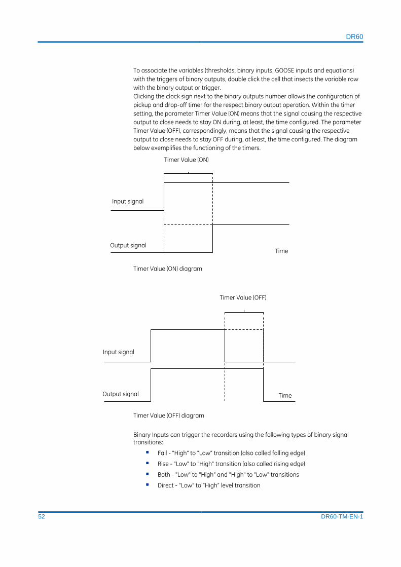
DR60
52 DR60-TM-EN-1
To associate the variables (thresholds, binary inputs, GOOSE inputs and equations)
with the triggers of binary outputs, double click the cell that insects the variable row
with the binary output or trigger.
Clicking the clock sign next to the binary outputs number allows the configuration of
pickup and drop-off timer for the respect binary output operation. Within the timer
setting, the parameter Timer Value (ON) means that the signal causing the respective
output to close needs to stay ON during, at least, the time configured. The parameter
Timer Value (OFF), correspondingly, means that the signal causing the respective
output to close needs to stay OFF during, at least, the time configured. The diagram
below exemplifies the functioning of the timers.
Timer Value (ON) diagram
Timer Value (OFF) diagram
Binary Inputs can trigger the recorders using the following types of binary signal transitions:
Fall - "High" to "Low" transition (also called falling edge)
Rise - "Low" to "High" transition (also called rising edge)
Both - "Low" to "High" and "High" to "Low" transitions
Direct - “Low” to “High” level transition
Input signal
Output signal
Timer Value (ON)
Time
Input signal
Output signal
Timer Value (OFF)
Time

DR60
53 DR60-TM-EN-1
6 Monitoring and Web Interface The DR60 has a web interface with monitoring options. To access the web interface
type in the DR60 IP Address using the Mozilla Firefox or Google Chrome browser from
computers, cellphones or tablet.
The default IP Addresses are shown in the Communication Chapter. In case the
default IP address has been changed and the user cannot recall it, use the IP
Scanning tool in the DR60 Configurator communication menu in order to recover it
refer to section (IP Address Scanning in the Configuration Chapter.
The DR60 web interface allows the user to:
Monitor real time calculated and measured values
Verify device information as serial number, CORTEC and others
Verify the device status
Check information on recorders and the created COMTRADE files. The table
below shows the available data to monitor on this page.
Start a manual trigger
Change de internal clock time
The DR60 also have a MMS server that can be access by IEC 61850 MMS clients to
monitor its internal variables, such as: binary I/O status, measurements, alarms etc.
The DR60 can support up to 20 MMS clients. The web interface connects as a MMS
client (counting as 1 clients per web interface).
Records page data:
Item Description
Recorder status Shows if the respective recorder is enabled or disabled
Recording made Shows that a trigger was generated*
Fault number Shows how many triggers were generated**
Memory used Shows the percentage usage of the respective recorder
Pre-trigger time Shows the pre-trigger time configured
Post-trigger time Shows the post-trigger time configured
Maximum record time Shows the maximum recorder time configured
Retrigger enabled Shows if the retrigger is enabled or disabled
Sample rate Shows the configured sampling rate for the respective recorder
Inhibition time Shows the duration that the trigger generation will be disabled***
Inhibition count Shows how many consecutive triggers within the inhibition time window are needed to enable the trigger inhibition***
Inhibition window Shows the time that is needed to enable the trigger inhibition***
*This information is 1 when record is generated and 0 during the record generation.
**The counter restarts when the equipment reboots or a new configuration is sent.

DR60
54 DR60-TM-EN-1
***Parameter configured in configuration tab Recording> Disable for.

DR60
55 DR60-TM-EN-1
DR60
Digital Recorder
Chapter 5: Records
This chapter details all types of registers created by the DR60.
1 Wave Form Records The waveform recorder registers the actual voltage or current signal being applied to
the analog channels. It captures the instantaneous values of the signal at a
configurable sampling rate of 256 or 512 samples/cycle.
The condition that initiated the waveform recording is called trigger. A trigger
happens whenever there’s a violation of digital (binary or GOOSE inputs) or analog
thresholds. Other ways to create waveform records are by cross-trigger signal
coming from another recorder or by a manual trigger.
1.1 Recorded Values The following values are recorded by the waveform recorder:
Voltage waveform of all voltage circuits (A, B, C, and N);
Current waveform of all current circuits (A, B, C, and N);
Transducer waveform of all transducer channels;
Binary Inputs
Binary Outputs
GOOSE Inputs
1.2 Recording Times by Trigger Once triggered, the following parameters are considered by the waveform recorder:
Parameter Allowed values Increment
Pre-fault time (tpre) 0 … 5 s 0.1 s
Post-fault time (tpos) 0 … 30 s 0.1 s
Maximum Record time
(tmax) 1 … 30 s 0.1 s
The Maximum Record time configures the maximum duration that the register can
reach. If consecutive retriggers or a sustained fault happens, the Maximum Record
time establishes the limit of time that the COMTRADE file will register.
DR60
56 DR60-TM-EN-1
The maximum duration of the fault record is 30 seconds.
1.3 Sampling Rate The wave recorder sampling rate is user-selectable between 256 and 512
samples/cycle. The size of the records is proportionally affected.
Both analog and digital inputs are recorded at the same sampling rate depending on
the type of recorder, i.e. waveform fault records: 256 and 512 samples/cycle and
Disturbance and continuous disturbance recorder: 1, 4 or 4 samples/cycle.
1.4 Trigger Burst Limiter
There is a user-configurable trigger burst limiter for the waveform recorder.
The burst limiter is based on the number of triggers time interval (both parameters
are user-configurable). When the limit is exceeded, recording will be disabled for a
period of time defined by the user.
This configuration aims to prevent excessive processing demand from jeopardizing
the device functioning.
Parameter Allowed values Increment
Number of triggers 1 … 16 1
Time interval 1 … 60 s 1 s
Disabling time 1 … 30 min 1 min
2 Re-trigger and Record Concatenation When two or more consecutive triggers happen, case the post-fault time of the first
trigger and the pre-fault time of the second trigger cross each other, then the DR60
concatenates both records and stores it in a single COMTRADE file.
In the figure below, if the time T≤ pre-fault time + post-fault time, then the records
are concatenated:
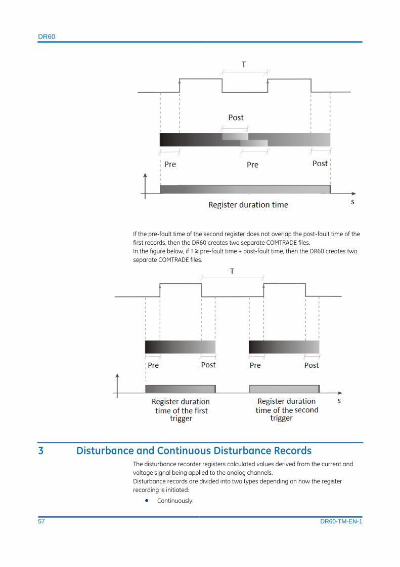
DR60
57 DR60-TM-EN-1
If the pre-fault time of the second register does not overlap the post-fault time of the
first records, then the DR60 creates two separate COMTRADE files.
In the figure below, if T ≥ pre-fault time + post-fault time, then the DR60 creates two
separate COMTRADE files.
3 Disturbance and Continuous Disturbance Records The disturbance recorder registers calculated values derived from the current and
voltage signal being applied to the analog channels.
Disturbance records are divided into two types depending on how the register
recording is initiated:
Continuously:

DR60
58 DR60-TM-EN-1
Derived measurements are continuously recorded. A new record is created at each
hour rollover. The record size depends on the number of derived measurements
selected by the user. The record can contain up to 128 measurements. The
continuous disturbance recorder has a parameter called Aggregation Period (10,0 –
60,0 min, 0,1 step). The recorder will create a new record every time the Aggregation
Period has elapsed.
By trigger:
The disturbance recorder can be triggered by a Boolean equation, by a cross-trigger
signal of another recorder, by a manual trigger using the Web Interface, or by the
triggering of the fault recorder. It is possible to select the derived quantity of
triggered disturbance records. If the quantities are not manually selected, the record
will consist of all the quantities available for measurement. The record size depends
of the number of derived measurements selected by the user.
Continuous and triggered disturbance records share the same mass storage area.
3.1 Recorded Values The table below presents all the available measurements from where the
disturbance register can record up to 128. Some measurements are divided into 3
different types for easy configuration. The intention is to divide the measurements
into classes of “importance” and they are: Fundamental, Basic and Other
measurements:
Measurement IEC 61850 Reference
Type MMXU
Fundamental Total active power MET/MMXU.TotW.mag.f
Fundamental Total reactive power MET/MMXU.TotVAr.mag.f
Fundamental Total apparent power MET/MMXU.TotVA.mag.f
Others Average power factor MET/MMXU.TotPF.mag.f
Fundamental Frequency MET/MMXU.Hz.mag.f
Others AB Line voltage (magnitude) MET/MMXU.PPV.phsAB.cVal.mag.f
Others BC Line voltage (magnitude) MET/MMXU.PPV.phsBC.cVal.mag.f
Others CA Line voltage (magnitude) MET/MMXU.PPV.phsCA.cVal.mag.f
Fundamental A Voltage (RMS) MET/MMXU.PhV.phsA.cVal.mag.f
Fundamental B Voltage (RMS) MET/MMXU.PhV.phsB.cVal.mag.f
Fundamental C Voltage (RMS) MET/MMXU.PhV.phsC.cVal.mag.f
Fundamental A Current (RMS) MET/MMXU.A.phsA.cVal.mag.f

DR60
59 DR60-TM-EN-1
Fundamental B Current (RMS) MET/MMXU.A.phsB.cVal.mag.f
Fundamental C Current (RMS) MET/MMXU.A.phsC.cVal.mag.f
Others A Phase active power MET/MMXU.W.phsA.cVal.mag.f
Others B Phase active power MET/MMXU.W.phsB.cVal.mag.f
Others C Phase active power MET/MMXU.W.phsC.cVal.mag.f
Others A Phase reactive power MET/MMXU.VAr.phsA.cVal.mag.f
Others B Phase reactive power MET/MMXU.VAr.phsB.cVal.mag.f
Others C Phase reactive power MET/MMXU.VAr.phsC.cVal.mag.f
Others A Phase apparent power MET/MMXU.VA.phsA.cVal.mag.f
Others B Phase apparent power MET/MMXU.VA.phsB.cVal.mag.f
Others C Phase apparent power MET/MMXU.VA.phsC.cVal.mag.f
Others A Phase power factor MET/MMXU.PF.phsA.cVal.mag.f
Others B Phase power factor MET/MMXU.PF.phsB.cVal.mag.f
Others C Phase power factor MET/MMXU.PF.phsC.cVal.mag.f
Others A Current Phasor (magnitude) MET/MMXU.A.phsA.instCVal.mag.f
Others B Current Phasor (magnitude) MET/MMXU.A.phsB.instCVal.mag.f
Others C Current Phasor (magnitude) MET/MMXU.A.phsC.instCVal.mag.f
Others A Current Phasor (angle) MET/MMXU.A.phsA.instCVal.ang.f
Others B Current Phasor (angle) MET/MMXU.A.phsB.instCVal.ang.f
Others C Current Phasor (angle) MET/MMXU.A.phsC.instCVal.ang.f
Others A Voltage Phasor (magnitude) MET/MMXU.PhV.phsA.instCVal.mag.f
Others B Voltage Phasor (magnitude) MET/MMXU.PhV.phsB.instCVal.mag.f
Others C Voltage Phasor (magnitude) MET/MMXU.PhV.phsC.instCVal.mag.f
Others A Voltage Phasor (angle) MET/MMXU.PhV.phsA.instCVal.ang.f
Others B Voltage Phasor (angle) MET/MMXU.PhV.phsB.instCVal.ang.f
Others C Voltage Phasor (angle) MET/MMXU.PhV.phsC.instCVal.ang.f
MSQI

DR60
60 DR60-TM-EN-1
Basic Current positive sequence (magnitude)
MET/MSQI.SeqA.c1.instCVal.mag.f
Basic Current positive sequence (angle) MET/MSQI.SeqA.c1.instCVal.ang.f
Basic Current negative sequence (magnitude)
MET/MSQI.SeqA.c2.instCVal.mag.f
Basic Current negative sequence (angle) MET/MSQI.SeqA.c2.instCVal.ang.f
Basic Current zero sequence (magnitude) MET/MSQI.SeqA.c3.instCVal.mag.f
Basic Current zero sequence (angle) MET/MSQI.SeqA.c3.instCVal.ang.f
Basic Voltage positive sequence (magnitude)
MET/MSQI.SeqV.c1.instCVal.mag.f
Basic Voltage positive sequence (angle) MET/MSQI.SeqV.c1.instCVal.ang.f
Basic Voltage negative sequence (magnitude)
MET/MSQI.SeqV.c2.instCVal.mag.f
Basic Voltage negative sequence (angle) MET/MSQI.SeqV.c2.instCVal.ang.f
Basic Voltage zero sequence (magnitude) MET/MSQI.SeqV.c3.instCVal.mag.f
Basic Voltage zero sequence (angle) MET/MSQI.SeqV.c3.instCVal.ang.f
MHAI
Basic Current total harmonic distortion MET/MHAI.ThdA.phsA.cVal.mag.f
Basic Current total harmonic distortion MET/MHAI.ThdA.phsB.cVal.mag.f
Basic Current total harmonic distortion MET/MHAI.ThdA.phsC.cVal.mag.f
Basic Voltage total harmonic distortion MET/MHAI.ThdPhV.phsA.cVal.mag.f
Basic Voltage total harmonic distortion MET/MHAI.ThdPhV.phsB.cVal.mag.f
Basic Voltage total harmonic distortion MET/MHAI.ThdPhV.phsC.cVal.mag.f
MMXN
Fundamental Frequency MET/MMXN.Hz.mag.f
Fundamental Voltage (RMS) MET/MMXN.Vol.mag.f
Fundamental Current (RMS) MET/MMXN.Amp.mag.f
Fundamental Phase active power MET/MMXN.Watt.mag.f
Fundamental Phase reactive power MET/MMXN.VolAmpr.mag.f
Fundamental Phase apparent power MET/MMXN.VolAmp.mag.f
Others Phase power factor MET/MMXN.PwrFact.mag.f
MHAN
Basic Current total harmonic distortion MET/MHAN.ThdAmp.mag.f
Basic Voltage total harmonic distortion MET/MHAN.ThdVol.mag.f
TGSN
Transducer (magnitude) MET/TGSN.GenSv.instMag.f
Digital inputs

DR60
61 DR60-TM-EN-1
GOOSE inputs DIG/GOOSEGGIO1
Digital inputs DIG/DIGITALGGIO1
Digital outputs DIG/OUTPUTGGIO1
3.2 Recording Times by Trigger
Once triggered, the following parameters are considered by the disturbance
recorder:
Parameter Allowed values Increment
Pre-fault time (tpre) 0 … 2 min 0.1 min
Post-fault time (tpos) 0 … 60 min 0.1 min
Maximum Record time (tmax) 1 … 60 min 0.1 min
The Maximum Record time configures the maximum duration that the register can
reach. If consecutive retriggers or a sustained fault happens, the Maximum Record
time establishes the limit of time that the COMTRADE file will register.
The maximum duration of the disturbance record is 60 minutes.
3.3 Sampling Rate The disturbance recorder and the continuous disturbance recorder have
independently configurable sampling rate that can be set to: 1, 2 or 4 samples/cycle.
The binary inputs in the disturbance register are recorded with the same sapling rate
as the analog channels.
3.4 Trigger Burst Limiter There is a user-configurable trigger burst limiter for the disturbance recorder which is
identical to the waveform recorder limiter Trigger Burst Limiter 1.4.
4 SOE - Sequence of Events Records The sequence of events recorder registers the status of the binary inputs, binary
output and GOOSE inputs. The recorder creates a XML file that groups the events
according to COMFEDE standard (IEEE C37.239-2010 Standard for Common Format
for Event Data Exchange).
The events in the SOE are recorded with accuracy better than 100µs.
The parameter “Aggregation Period” sets the duration of the records and time
interval that new records are created. The aggregation period can be configured
from 1 – 1440 min.

DR60
62 DR60-TM-EN-1
4.1 Sampling Rate The SOE sampling rate is the same sampling rate configured in the Waveform
Recorder: 256 or 512 samples/cycle. In case the Waveform in not enabled in the
configuration the SOE recorder will use 256 samples/cycle as sampling rate.
5 Record Format and Naming, and Mass Storage Capacity
5.1 Record Format
Records are created in accordance with the COMTRADE standard IEEE C37.111-2013,
IEEE Standard Common Format for Transient Data Exchange for Power Systems. The
COMTRADE records in the DR60 are comprised by the “.cfg” and “.dat” files described
in the standard.
5.2 Record Naming
Records are named using the COMNAME methodology, according to IEEE C37.232-
2011, Common Format for Naming Time Sequence Data Files (COMNAME).
Fault, Disturbance, Steady-state, and Sequence of Events records are named as
follows:
STARTDATE,STARTTIME,TIMECODE,STATIONID,DEVICEID,COMPANY,DURATION.CFG
STARTDATE,STARTTIME,TIMECODE,STATIONID,DEVICEID,COMPANY,DURATION.DAT
The table below describe each parameter in the file name.
Parameter Format Description
STARTDATE yymmdd Record’s start date
(year, mounth, day)
STARTTIME hhmmssuuuuuu Record’s start time
(hour, minutes, seconds, microsseconds)
TIMECODE soohmm Indication of timezone offset
(the last three characters are included only when fractional
hours are in use)

DR60
63 DR60-TM-EN-1
STATIONID Location of the equipment, configurable in:
GENERAL > LOCATION
(up to 255 characters)
DEVICEID Equipment identifier, configurable in:
GENERAL > IDENTIFIER
(up to 61 characters)
COMPANY Equipment owner description, configurable in:
GENERAL > OWNER
(up to 255 characters)
DURATION sssssuuuuuu Duration of the record
(seconds, microsseconds)
5.3 Mass Storage Capacity
Memory type SSD Capacity
Fault 19,1 GB
Disturbance 7,7 GB
SOE 1 GB
Trend 1 GB
The equipment can be configured to automatically remove the oldest records as the
soon as mass storage occupation exceeds 90%.
All DR60 files including configuration and records are stored in the SSD non-volatile
memory.
6 Record Management and Access In order to retrieve the COMTRADE files from the DR60, user can use either a FTP
client or the DR Manager tool.
DR60
64 DR60-TM-EN-1
The DR60 is equipped with a FTP server, which means that any FTP client such as:
Internet Explorer, Mozilla Firefox, Google Chrome or the Windows Explorer are able to
connect the DR60 and access the COMTRADE files.
To do so, using the FTP client, access the DR60 address: ftp://DR60_IP_ADDRESS and
use the following credentials:
User: ftp
Password: 123ftp
The password cannot be changed and the FTP access is read-only.
In order to download the records using the DR Manager, open the DR Manager tool
and follow the instructions below:
6.1 Creating Installations Within the DR Manager software, the process to create a new Installation is:
1. Click <SETTINGS> menu and then click <INSTALLATIONS>;
2. Click <NEW> to create. Type the Installation's name and description and then
press <OK>.
The user can view the list of registered substations and add, edit, or remove a
substation. Substations can only be removed without any equipment being
associated.
6.2 Creating Devices
The user can view the list of registered equipment, add, edit, or remove some
equipment. Equipment can only be removed when there is no transmission line
associated and if the Auto Polling is disabled.
The process to create a new device is:
Click <SETTINGS> menu and then click <DEVICES>;
Click <NEW> to create.
At <HOST>, type equipment's IP address;
Choose the model of the device: RPV or DR60
Choose device installation in the Installation list;
Click at <Get Info> and then press <Ok>.
The figure below shows the Device configuration window.

DR60
65 DR60-TM-EN-1
Device window
There are two parameters to be configured by the user:
Enable Auto COMTRADE Download: When enabled, the unit will be part of the Auto
Polling process, where records not yet saved are automatically downloaded.
Enable Auto Refreshing: When enabled, the unit will be part of the process of Auto
Refresh, where the equipment state will be updated automatically during the
process.
The user can change the equipment host address, and enable or disable the "Enable
Auto COMTRADE Download" and "Enable Auto Refreshing". At the end of the editing,
the software automatically communicates with the equipment in order to upgrade
the name and location information.
If the equipment is associated with any transmission, a message will be shown to the
user at the beginning of the Edit.

DR60
DR60
Digital Recorder
Chapter 6: Communications
This chapter provides detailed information about the communication options and
how to configure them
1 Communication Interfaces – Slot B
The DR60 has two Ethernet interfaces that can be either electrical or optical and two
serial interfaces with DB9 female connectors, serial A is RS232 and serial B is RS232.
1.1 Electrical and Optical Ethernet The DR60 has 2 Ethernet interfaces named Ethernet 1 and Ethernet 2. The table
below describes the usage of each port:
Port Usage
Ethernet 1 Configuration, monitoring, GOOSE
publication/subscription, MMS report control
block publication, firmware upgrade, log and
registers download.
Ethernet 2 Configuration, monitoring, firmware upgrade, log and registers download.
Both interfaces can be either optical with LC connectors or electrical with RJ45
connectors.
The figure below shown the pinout diagram.

DR60
68 DR60-TM-EN-1
Electrical and optical Ethernet inputs
To minimize EMC effects, the use of fiber-optic cables is recommended for
applications where the length of the cable is greater than 3 m or connection between
panels.
Note:
Applying signals to the Ethernet ports at 50 MHz frequency may cause mal functioning of the ports.
1.1.1 Ethernet Port Default Settings
The Ethernet interface default settings are:
Default Setting
Parameter Ethernet port 1 Ethernet port 2
IP Address 192.168.0.199 192.168.1.199
Network mask 255.255.255.0 255.255.255.0
Gateway 192.168.0.254 192.168.1.254
1.2 Serial Port The DR60 has 2 serial ports with DB9 female connectors. The serial ports can be used
for configuration download/upload, firmware upgrade and logs download.
The Serial A is RS232 type. The Serial B is RS232 and RS485. The pinout of the serial
ports is shown in the figure below.

DR60
69 DR60-TM-EN-1
Serial communication port
2 Communication Ports and Protocols
The DR60 web interface was designed using the GE Predix platform and it can be
accessed using Mozilla Firefox or Google Chrome browser from computers,
cellphones or tablet.
The web interface uses the follow ports and protocols. These ports must be properly
configured in the routers and firewalls for the communication work completely.
Port Protocol Use
21 FTP Download COMTRADE files
22 SSH Configuration download and upload, logs download and firmware
upgrade
80 HTTP Web monitoring interface
102 MMS MMS Report control block
4220 UDP/IP IP recovery tool Ethernet 1
4221 UDP/IP IP recovery tool Ethernet 2
502 TCP MODBUS interface

DR60
70 DR60-TM-EN-1
3 Recovering the DR60 IP Address
To verify recover the DR60 IP address or to validate the communication between the
device and the computer, the DR60 has a scanning tool in the DR60 Configurator
tool, which scans the network returning the IP Address of the found DR60. The
scanning tool in located in the Communication menu and is described in the
Configuration Chapter.
4 Accessing the Equipment
The DR60 has basically two means of access. The windows tool named DR60
Configurator used to configure, download logs and firmware upgrade; and the Web
Interface for monitoring and remote trigger. Detailed information on how to proceed
the access using both ways is described in the Configuration Chapter.
The minimum requirements for the web interface is described in the next section and
the for the DR60 Configuration tool in the Installation Chapter.
4.1 Web Interface Minimum Requirements
Web interface requirement: Internet Explorer version 7 or higher, or Mozilla Firefox
version 3.0 or higher;
DR60
DR60
Digital Recorder
Chapter 7: Installation
This chapter provides information about the product installation.
1 Handling the Goods Our products are of robust construction but require careful treatment before
installation on site. This section discusses the requirements for receiving and
unpacking the goods, as well as associated considerations regarding product care
and personal safety.
Before lifting or moving the equipment you should be familiar with the Safety Information chapter of this manual.
1.1 Receipt of the Goods On receipt, ensure the correct product has been delivered. Unpack the product
immediately to ensure there has been no external damage in transit. If the product
has been damaged, make a claim to the transport contractor and notify us promptly.
For products not intended for immediate installation, repack them in their original
delivery packaging.
1.2 Unpacking the Goods When unpacking and installing the product, take care not to damage any of the parts
and make sure that additional components are not accidentally left in the packing or
lost. Do not discard any CDROMs or technical documentation. These should
accompany the unit to its destination substation and put in a dedicated place.
The site should be well lit to aid inspection, clean, dry and reasonably free from dust
and excessive vibration. This particularly applies where installation is being carried
out at the same time as construction work.
1.3 Storing the Goods If the unit is not installed immediately, store it in a place free from dust and moisture
in its original packaging. Keep any de-humidifier bags included in the packing. The
de-humidifier crystals lose their efficiency if the bag is exposed to ambient
conditions. Restore the crystals before replacing it in the carton. Ideally regeneration
should be carried out in a ventilating, circulating oven at about 115°C. Bags should
be placed on flat racks and spaced to allow circulation around them. The time taken

DR60
72 DR60-TM-EN-1
for regeneration will depend on the size of the bag. If a ventilating, circulating oven is
not available, when using an ordinary oven, open the door on a regular basis to let
out the steam given off by the regenerating silica gel.
On subsequent unpacking, make sure that any dust on the carton does not fall inside.
Avoid storing in locations of high humidity. In locations of high humidity the
packaging may become impregnated with moisture and the de-humidifier crystals
will lose their efficiency.
The device can be stored between –25º to +70ºC for unlimited periods or between -
40°C to + 85°C for up to 96 hours (see technical specifications).
1.4 Dismantling the Goods If you need to dismantle the device, always observe standard ESD (Electrostatic
Discharge) precautions. The minimum precautions to be followed are as follows:
Use an antistatic wrist band earthed to a suitable earthing point.
Avoid touching the electronic components and PCBs.
2 Normal Use of the Equipment In order to maintain the equipment integrity, levels of protection and assure user
safety, the shall be installed in an enclosed panel with recommended ingress
protection rating of IP42 or above. The DR60 shall be kept in an environment where it
is protected against impact and water. The enclosing panel shall ensure that the
equipment rear connections are not exposed, meanwhile maintaining adequate
temperature and humidity condition for the devices. Furthermore, the equipment
shall have all their rear connectors attached, even if not being used, in order to keep
their levels of ingress protection as high as possible.
The DR60 is IEC 60255-27:2014 Overvoltage Category III and Pollution Degree II
(using the 100-250 Vdc / 110-240 Vac power supply); or Overvoltage Category II and
Pollution Degree II (using the 24-48 Vdc power supply). These ratings allow mounting
of the equipment indoors or in an outdoor (extended) enclosure where the equipment
is protected against exposure to direct sunlight, precipitation, and full wind pressure.
During the normal use of the device only its frontal panel shall be accessible.
3 Mounting the Device
3.1 DR60 Mechanical Installation The screws used for fixation are of the M6 type.
It is possible to order an optional support for installation of one or two units adapted
to a 19-inch rack. To install either a single or two modules of the DR60 use the
optional supports shown in the Installation Chapter - Accessories
For information about the equipment dimensions, refer to the Technical
Specifications Chapter.

DR60
73 DR60-TM-EN-1
The equipment is designed for outdoor installation in proper panel. The panel must
be designed for the environmental conditions to which it is subject.
The DR60 should always be sheltered from the weather. For indoor use, the
equipment must be installed inside panel with IP41 (IEC) enclosure protection or
minimal type 3 (NEMA). For outdoor use, the equipment must be installed inside panel
with IP55 (IEC) enclosure protection or type 3, 3X, 3S or 3SX (NEMA), according to the
local environmental conditions, complying the IEC 60529 and NEMA 250-2003
standards requirement.
The panels should be submitted to insulation test according to IEC 60255-5 standard
(minimum insulation resistance of 10 MΩ and be submitted to test of dielectric
voltage insulation of 2kV a.c.)
An additional panel designed for the DR60 application environment may be provided
upon request. For more information on panel options, please contact GE Contact
Center.
DR60 Frontal Panel
It is recommended that 1 rack unit of space (1.75”) be kept unpopulated and free of
equipment above each DR60 to allow for a small amount of convectional airflow.
Although forced airflow is not necessary, any increase in airflow will result in a

DR60
74 DR60-TM-EN-1
reduction of ambient temperature that will improve long-term reliability of all
equipment mounted within the rack space.
4 Cables and Connectors This section describes the type of wiring and connections that should be used when
installing the device, as well as pin-out details.
Before carrying out any work on the equipment you should be familiar with the Safety Section and the ratings on the equipment’s rating label.
In order to meet the EMC CISPR22 emission levels, the power supply, CT, VT and
binary signals connection shall use screened (shielded) cables with screen coverage
of 70%; Core wires should have 2.0 mm² cross section and be as short as possible;
The shield should be connected to any of the two functional earth terminal screws
positioned on the upper and lower-middle parts of the frontal panel of the equipment
through short pigtails. Recommended lug terminal to the pigtail end connection.
4.1 Power Supply Connections
The unit can be powered from DC or AC power within the limits specified in the
Technical Specifications Chapter.
All power connections should use insulated flameproof screened/shielded cable with
a 2.0 mm2 cross section, 70° C (158 °F) thermal class, and 750 V insulation voltages.
To reduce the risk of electrical shock, pre-insulated tubular pin terminals should be
used on the ends of the power connections.
Pre-insulated tubular pin terminals
The pin terminals should be completely inserted into the connector supplied with the
unit so that no metallic parts are exposed, according to the picture below.
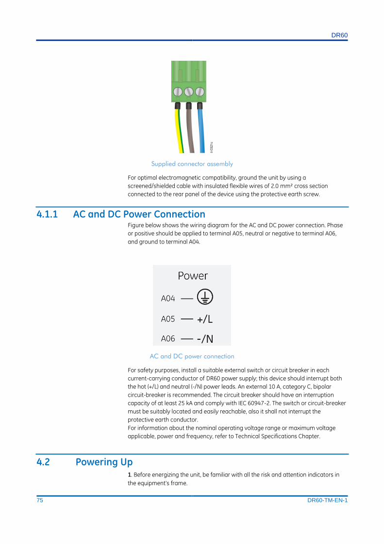
DR60
75 DR60-TM-EN-1
Supplied connector assembly
For optimal electromagnetic compatibility, ground the unit by using a
screened/shielded cable with insulated flexible wires of 2.0 mm² cross section
connected to the rear panel of the device using the protective earth screw.
4.1.1 AC and DC Power Connection Figure below shows the wiring diagram for the AC and DC power connection. Phase
or positive should be applied to terminal A05, neutral or negative to terminal A06,
and ground to terminal A04.
AC and DC power connection
For safety purposes, install a suitable external switch or circuit breaker in each
current-carrying conductor of DR60 power supply; this device should interrupt both
the hot (+/L) and neutral (-/N) power leads. An external 10 A, category C, bipolar
circuit-breaker is recommended. The circuit breaker should have an interruption
capacity of at least 25 kA and comply with IEC 60947-2. The switch or circuit-breaker
must be suitably located and easily reachable, also it shall not interrupt the
protective earth conductor.
For information about the nominal operating voltage range or maximum voltage
applicable, power and frequency, refer to Technical Specifications Chapter.
4.2 Powering Up 1. Before energizing the unit, be familiar with all the risk and attention indicators in
the equipment’s frame.
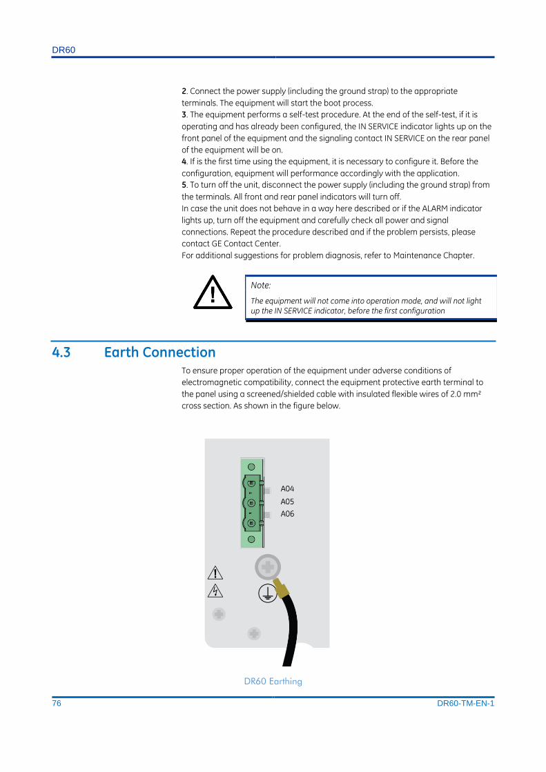
DR60
76 DR60-TM-EN-1
2. Connect the power supply (including the ground strap) to the appropriate
terminals. The equipment will start the boot process.
3. The equipment performs a self-test procedure. At the end of the self-test, if it is
operating and has already been configured, the IN SERVICE indicator lights up on the
front panel of the equipment and the signaling contact IN SERVICE on the rear panel
of the equipment will be on.
4. If is the first time using the equipment, it is necessary to configure it. Before the
configuration, equipment will performance accordingly with the application.
5. To turn off the unit, disconnect the power supply (including the ground strap) from
the terminals. All front and rear panel indicators will turn off.
In case the unit does not behave in a way here described or if the ALARM indicator
lights up, turn off the equipment and carefully check all power and signal
connections. Repeat the procedure described and if the problem persists, please
contact GE Contact Center.
For additional suggestions for problem diagnosis, refer to Maintenance Chapter.
Note:
The equipment will not come into operation mode, and will not light up the IN SERVICE indicator, before the first configuration
4.3 Earth Connection To ensure proper operation of the equipment under adverse conditions of
electromagnetic compatibility, connect the equipment protective earth terminal to
the panel using a screened/shielded cable with insulated flexible wires of 2.0 mm²
cross section. As shown in the figure below.
DR60 Earthing
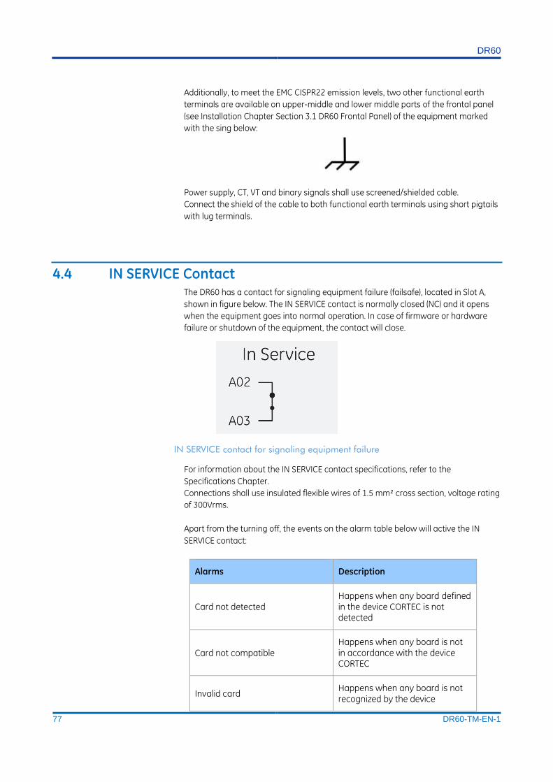
DR60
77 DR60-TM-EN-1
Additionally, to meet the EMC CISPR22 emission levels, two other functional earth
terminals are available on upper-middle and lower middle parts of the frontal panel
(see Installation Chapter Section 3.1 DR60 Frontal Panel) of the equipment marked
with the sing below:
Power supply, CT, VT and binary signals shall use screened/shielded cable.
Connect the shield of the cable to both functional earth terminals using short pigtails
with lug terminals.
4.4 IN SERVICE Contact The DR60 has a contact for signaling equipment failure (failsafe), located in Slot A,
shown in figure below. The IN SERVICE contact is normally closed (NC) and it opens
when the equipment goes into normal operation. In case of firmware or hardware
failure or shutdown of the equipment, the contact will close.
IN SERVICE contact for signaling equipment failure
For information about the IN SERVICE contact specifications, refer to the
Specifications Chapter.
Connections shall use insulated flexible wires of 1.5 mm² cross section, voltage rating
of 300Vrms.
Apart from the turning off, the events on the alarm table below will active the IN
SERVICE contact:
Alarms Description
Card not detected Happens when any board defined in the device CORTEC is not detected
Card not compatible Happens when any board is not in accordance with the device CORTEC
Invalid card Happens when any board is not recognized by the device

DR60
78 DR60-TM-EN-1
Record memory full Happens when the memory becomes 98% full
4.5 Optical IRIG-B Input Time synchronization is provided by temporal signal format IRIG-B004. The IRIG-B
ensures that the frequency of data acquisition stays constant and maintaining the
internal clock synchronized.
The DR60 has an optical IRIG-B input, located in Slot B, shown in figure below
Optical IRIG-B input
The equipment signals SYNC on the front panel when the data acquisition frequency
is in accordance with the equipment’s nominal acquisition frequency and the
equipment’s internal clock is updated.
To synchronize the equipment using fiber-optic input, use the appropriate fiber-optic
type, considering its minimum curvature radius. For information about the optical
input specifications, refer to the Technical Specification chapter
4.6 Serial ports The DR60 has 2 serial ports with DB9 female connectors. The serial ports can be used
for configuration download/upload, firmware upgrade and logs download.
The Serial A is RS232 type. The Serial B is RS232 and RS485. The pinout of the serial
ports is shown in the figure below.
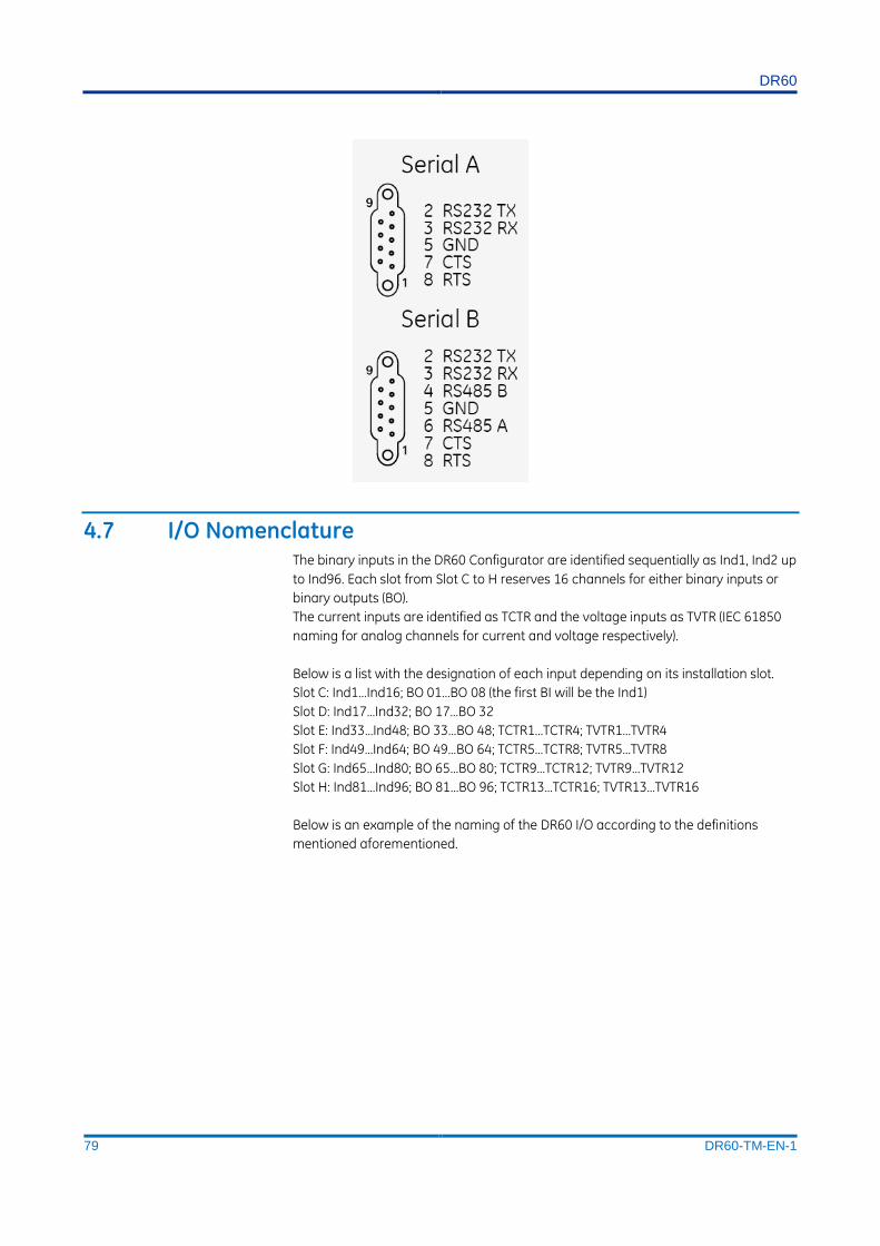
DR60
79 DR60-TM-EN-1
4.7 I/O Nomenclature The binary inputs in the DR60 Configurator are identified sequentially as Ind1, Ind2 up
to Ind96. Each slot from Slot C to H reserves 16 channels for either binary inputs or
binary outputs (BO).
The current inputs are identified as TCTR and the voltage inputs as TVTR (IEC 61850
naming for analog channels for current and voltage respectively).
Below is a list with the designation of each input depending on its installation slot.
Slot C: Ind1…Ind16; BO 01…BO 08 (the first BI will be the Ind1)
Slot D: Ind17…Ind32; BO 17…BO 32
Slot E: Ind33…Ind48; BO 33…BO 48; TCTR1…TCTR4; TVTR1…TVTR4
Slot F: Ind49…Ind64; BO 49…BO 64; TCTR5…TCTR8; TVTR5…TVTR8
Slot G: Ind65…Ind80; BO 65…BO 80; TCTR9…TCTR12; TVTR9…TVTR12
Slot H: Ind81…Ind96; BO 81…BO 96; TCTR13…TCTR16; TVTR13…TVTR16
Below is an example of the naming of the DR60 I/O according to the definitions
mentioned aforementioned.

DR60
80 DR60-TM-EN-1
Example of the binary and analog channels name tags
4.8 Binary Inputs and Outputs The binary inputs and outputs are supported in slots C to H of the DR60. There are
two different types of boards for the binary slots C and D, the first has 8 BO and 6 BI
and the second board has 16 BI. It is possible to use either board in any slots from C
to H.
A B C D E F G H

DR60
81 DR60-TM-EN-1
Binary inputs and outputs of the B2 board (8 BO + 6 BI)
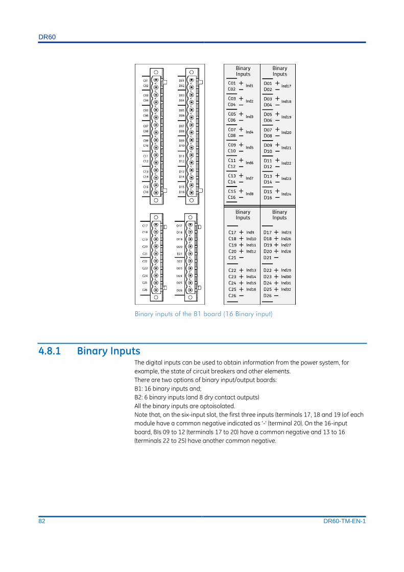
DR60
82 DR60-TM-EN-1
Binary inputs of the B1 board (16 Binary input)
4.8.1 Binary Inputs The digital inputs can be used to obtain information from the power system, for
example, the state of circuit breakers and other elements.
There are two options of binary input/output boards:
B1: 16 binary inputs and;
B2: 6 binary inputs (and 8 dry contact outputs)
All the binary inputs are optoisolated.
Note that, on the six-input slot, the first three inputs (terminals 17, 18 and 19 (of each
module have a common negative indicated as ‘-’ (terminal 20). On the 16-input
board, BIs 09 to 12 (terminals 17 to 20) have a common negative and 13 to 16
(terminals 22 to 25) have another common negative.
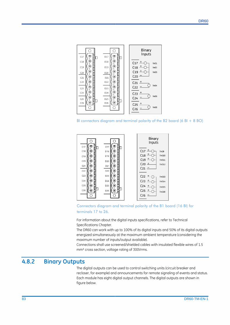
DR60
83 DR60-TM-EN-1
BI connectors diagram and terminal polarity of the B2 board (6 BI + 8 BO)
Connectors diagram and terminal polarity of the B1 board (16 BI) for
terminals 17 to 26.
For information about the digital inputs specifications, refer to Technical
Specifications Chapter.
The DR60 can work with up to 100% of its digital inputs and 50% of its digital outputs
energized simultaneously at the maximum ambient temperature (considering the
maximum number of inputs/output available).
Connections shall use screened/shielded cables with insulated flexible wires of 1.5
mm² cross section, voltage rating of 300Vrms.
4.8.2 Binary Outputs The digital outputs can be used to control switching units (circuit breaker and
recloser, for example) and announcements for remote signaling of events and status.
Each module has eight digital output channels. The digital outputs are shown in
figure below.
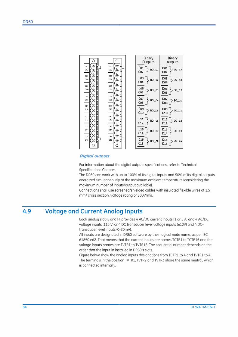
DR60
84 DR60-TM-EN-1
Digital outputs
For information about the digital outputs specifications, refer to Technical
Specifications Chapter.
The DR60 can work with up to 100% of its digital inputs and 50% of its digital outputs
energized simultaneously at the maximum ambient temperature (considering the
maximum number of inputs/output available).
Connections shall use screened/shielded cables with insulated flexible wires of 1.5
mm² cross section, voltage rating of 300Vrms.
4.9 Voltage and Current Analog Inputs Each analog slot (E and H) provides 4 AC/DC current inputs (1 or 5 A) and 4 AC/DC
voltage inputs (115 V) or 4 DC transducer level voltage inputs (±10V) and 4 DC-
transducer level inputs (0-20mA).
All inputs are designated in DR60 software by their logical node name, as per IEC
61850 ed2. That means that the current inputs are names TCTR1 to TCTR16 and the
voltage inputs names are TVTR1 to TVTR16. The sequential number depends on the
order that the input in installed in DR60’s slots.
Figure below show the analog inputs designations from TCTR1 to 4 and TVTR1 to 4.
The terminals in the position TVTR1, TVTR2 and TVTR3 share the same neutral, which
is connected internally.

DR60
85 DR60-TM-EN-1
Voltage and current analog inputs
4.9.1 Current Analog Inputs Each analog board of the DR60 has 4 current inputs. The inputs types are AC/DC 1A,
AC/DC 5A, AC/DC 1A and 5A (high accuracy for metering) or DC transducer 0-20mA.
Before making the electrical connection, make sure the signal is applied in
accordance with the technical specifications of the equipment.
For information about the analog current inputs specifications, refer to Technical
Specifications Chapter.
Connections shall use screened/shielded cables with insulated flexible wires of at
least 2.5 mm² cross section, 8 mm ring terminals, and M3 holes, voltage rating of
300Vrms.
4.9.2 Voltage Analog Inputs
Each analog board of the DR60 has 4 voltage inputs. The inputs types are AC/DC
115V (for protection), AC/DC 115V (high accuracy for metering) or DC transducer
±10V.
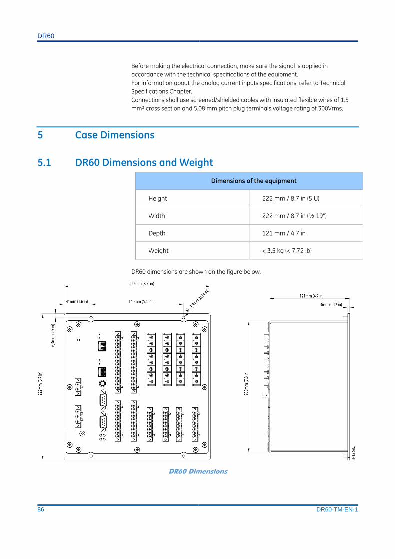
DR60
86 DR60-TM-EN-1
Before making the electrical connection, make sure the signal is applied in
accordance with the technical specifications of the equipment.
For information about the analog current inputs specifications, refer to Technical
Specifications Chapter.
Connections shall use screened/shielded cables with insulated flexible wires of 1.5
mm² cross section and 5.08 mm pitch plug terminals voltage rating of 300Vrms.
5 Case Dimensions
5.1 DR60 Dimensions and Weight
Dimensions of the equipment
Height 222 mm / 8.7 in (5 U)
Width 222 mm / 8.7 in (½ 19'')
Depth 121 mm / 4.7 in
Weight < 3.5 kg (< 7.72 lb)
DR60 dimensions are shown on the figure below.
DR60 Dimensions

DR60
87 DR60-TM-EN-1
5.2 Panel Cutout The DR60 panel cutout is shown in the figure below.
Panel cutout for DR60 installation
5.3 Accessories
DR60 accessories
Q061 Mounting panel to install two DR60 in a 19-inch rack + blank plate to cover one cutout in case only one DR60 is being used.

DR60
88 DR60-TM-EN-1
5.3.2 Mounting Panel for Two DR60 (Q061) Mounting Panel to install one/two DR60 in a 19-inch rack is shown in figure below.
The mounting panel comes with a blank plate to cover one cutout in case only one
DR60 is being used.
Double mounting chassis to install two DR60 in a 19-inch rack
6 DR60 Configurator Tools Installation The DR60 Configuration Tool is the Windows based software responsible for device configuration, logs download and IED embedded software (firmware) upgrade.
6.1 Minimal requirements The minimum hardware requirements, supported operational system and
applications needed for the installation and implementation of the DR60
Configurator are described below.
Minimum hardware requirements:
Processor 1 GHz or higher, 32-bit (x86) or 64-bit (x64);
Minimum 1 GB RAM (32-bit) or 2 GB RAM (64-bit);
Minimum 1 GB free space on disk;
DirectX 9 or higher.
Supported operational system:
Windows© XP 32-bit (x86) or 64-bit (x64).
Windows© 7 32-bit (x86) or 64-bit (x64).
Applications:
Microsoft dot.Net 4.0 version or higher;
FTDI Driver 2.08.24 version or higher;
Microsoft Visual C++ 2010 Redistributable Package (x86) SP1;

DR60
89 DR60-TM-EN-1
Windows© Installer 3.1;
Microsoft Visual C++ 2010 Redistributable Package (x86) (Must be installed
even for x64 Windows©);
Microsoft Visual C++ 2010 Redistributable Package (x64) (Must be installed
only for x64 Windows©).
To install the DR60 Configurator, it is necessary be the system administrator. To verify
if the user is the system administrator, access the Control Panel in Windows©, and go
to Users Accounts.

DR60
DR60
Digital Recorder
Chapter 8: Maintenance
This chapter provides information about proper equipment maintenance and
troubleshooting.
The troubleshooting part of the chapter allows an error condition on the IED to be
identified so that appropriate corrective action can be taken.
1 Maintenance
1.1 Maintenance Checks In view of the critical nature of the application, GE Grid products should be checked
at regular intervals to confirm they are operating correctly.
The devices are self-supervising, most problems will result in an alarm, indicating
that remedial action should be taken. However, some periodic tests should be
carried out to ensure that they are functioning correctly and that the external wiring
is intact. It is the responsibility of the customer to define the interval between
maintenance periods. If your organisation has a Preventative Maintenance Policy, the
recommended product checks should be included in the regular program.
Maintenance periods depend on many factors, such as:
The operating environment
The accessibility of the site
The amount of available manpower
The importance of the installation in the power system
The consequences of failure
Although some functionality checks can be performed from a remote location, these
are predominantly restricted to checking that the unit is measuring the applied
currents and voltages accurately, and checking the circuit breaker maintenance
counters. For this reason, maintenance checks should also be performed locally at
the substation.
Before carrying out any work on the equipment you should be familiar with the contents of the Safety Section and the ratings on the equipment’s rating label.
While the dr60 performs continual self-tests, it is recommended that maintenance be
scheduled with other system maintenance. This maintenance can involve in-service,
out-of-service, or unscheduled maintenance.

DR60
91 DR60-TM-EN-1
1.1.1 In-service maintenance 1. Visual verification of the analog values integrity, such as voltage and current (in
comparison to other devices on the corresponding system).
2. Visual verification of active alarms and LED indications.
3. Visual inspection for any damage, corrosion, dust, or loose wires.
4. Log file download with further events analysis.
1.1.2 Out-of-service maintenance 1. Check wiring connections for firmness.
2. Analog values (currents, voltages) injection test and metering accuracy verification.
Calibrated test equipment is required.
3. Thresholds verification
4. Contact inputs and outputs verification. This test can be conducted by direct
change of state forcing or as part of the system functional testing.
5. Visual inspection for any damage, corrosion, or dust.
6. Log file download with further events analysis.
1.1.3 Unscheduled maintenance (system interruption) 1. View the event recorder, logs and oscillography for correct operation of inputs,
outputs, and elements
1.2 Back up and restore settings Back up a copy of the in-service settings for each commissioned device, so as to
revert to the commissioned settings after inadvertent, unauthorized, or temporary
setting changes are made, after the settings defaulted due to firmware upgrade, or
when the device has to be replaced. For information on how to download and upload
configurations refer to the Configuration Chapter.
1.3 Measurement Accuracy If the power system is energised, the measured values can be compared with known
system values to check that they are in the expected range. If they are within a set
range, this indicates that the A/D conversion and the calculations are being
performed correctly.
Alternatively, the measured values can be checked against known values injected
into the device using the test block, (if fitted) or injected directly into the device's
terminals..
1.4 Replacing the Unit If your product should develop a fault while in service, depending on the nature of
the fault, the watchdog contacts will change state and an alarm condition will be
flagged. In the case of a fault, you should normally replace the cradle which slides
easily out of the case. This can be done without disturbing the scheme wiring.
In the unlikely event that the problem lies with the wiring and/or terminals, then you
must replace the complete device, rewire and re-commission the device.

DR60
92 DR60-TM-EN-1
If the repair is not performed by an approved service centre, the warranty will be invalidated.
Before carrying out any work on the equipment, you should be familiar with the contents of the Safety Information Chapter as well as the ratings on the equipment’s rating label. This should ensure that no damage is caused by incorrect handling of the electronic components.
Before working at the rear of the unit, isolate all voltage and current supplying it.
1.5 Cleaning
Before cleaning the device, ensure that all AC and DC supplies and transformer connections are isolated, to prevent any chance of an electric shock while cleaning.
Only clean the equipment with a lint-free cloth dampened with clean water. Do not
use detergents, solvents or abrasive cleaners as they may damage the product's
surfaces and leave a conductive residue.
1.6 Watchdog The DR60 presents an internal watchdog algorithm. This algorithm verifies, every
second, if the device’s system is responding correctly. Case the system does not
respond the device performs a hardware reboot while the IN SERVICE relay signals
that the DR60 is off.
2 DR60 Troubleshooting
3 DR60 Firmware Update The DR60 firmware update is carried out by the DR60 Configurator tools. For details
on the firmware update procedure refer to the Configuration Chapter.
4 Equipment Return

DR60
93 DR60-TM-EN-1
All parts and components comprising Reason devices shall be repaired exclusively by
GE. In case of equipment malfunction, the customer shall get in contact with GE
Contact Centre and never attempt to repair the device by his own.
To request equipment repair service, call GE to check out shipment options and
receive the technical assistance order code.
The equipment shall be packed in its original package or a suitable package to
protect against impacts and moisture.
5 Instructions for Equipment Repair/Service for Service
Personnel The instructions presented in this topic shall only be followed by GE service
Personnel.
In case any repair needs to be done, follow the procedure below to ensure the safety
of the operation.
1. Disconnect power supply;
2. Disconnect all other connections leaving the grounding strap to be removed
at the end;
3. Perform a visual inspection to make sure the equipment is isolated;
4. Position the device in place where there is free space to work and make
sure to install proper working and safety warnings at the location, also keep
available all tools and aids that is going to be used;
5. Wait a few minutes so the capacitors may discharge;
6. Disassemble the device by unscrewing the case screws and pulling up the
top side of the case; after that, carry on with the proper repairs. Keep in
mind that disassembling the equipment may expose sensitive electronic
circuitry. Take suitable precautions against electrostatic voltage discharge
(ESD) to avoid damage to the equipment.
After the repairs are done, follow the procedure below in order to verify the safe state
of the equipment and to put it back into operation.
1. Reconnect all internal cable that have been removed for the repair;
2. Perform a visual inspection on the device to make sure there are no
remainders of the repair service inside the casing or any other
noncompliance;
3. Place back the top side of the case and fasten it using the proper screws;
4. Connect the grounding strap and then the power supply to the equipment;
5. Wait for the equipment to initialize, it will run self-diagnostic routines and if
everything is right the “Ready” LED on its front panel will light up indicating
the equipment is safe and operational;
Follow the procedures in the DR60
Digital Recorder
6. Chapter 2: Safety Information.

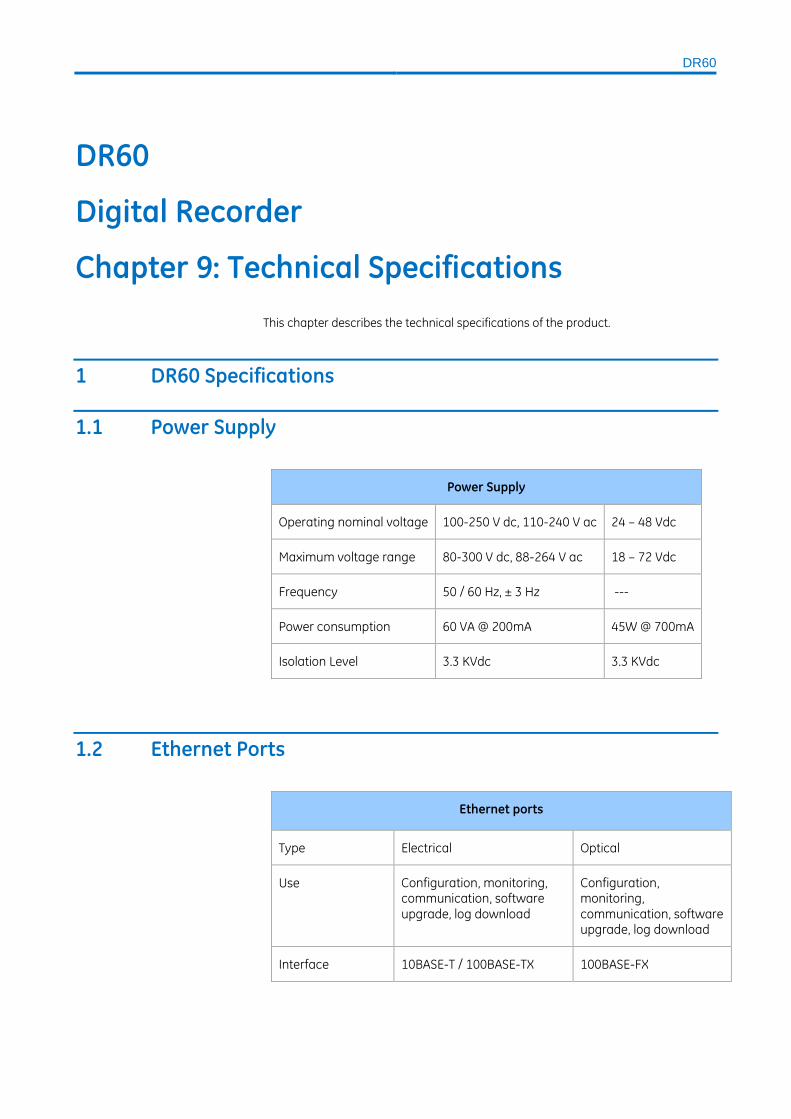
DR60
DR60
Digital Recorder
Chapter 9: Technical Specifications
This chapter describes the technical specifications of the product.
1 DR60 Specifications
1.1 Power Supply
Power Supply
Operating nominal voltage 100-250 V dc, 110-240 V ac 24 – 48 Vdc
Maximum voltage range 80-300 V dc, 88-264 V ac 18 – 72 Vdc
Frequency 50 / 60 Hz, ± 3 Hz ---
Power consumption 60 VA @ 200mA 45W @ 700mA
Isolation Level 3.3 KVdc 3.3 KVdc
1.2 Ethernet Ports
Ethernet ports
Type Electrical Optical
Use Configuration, monitoring, communication, software upgrade, log download
Configuration, monitoring, communication, software upgrade, log download
Interface 10BASE-T / 100BASE-TX 100BASE-FX
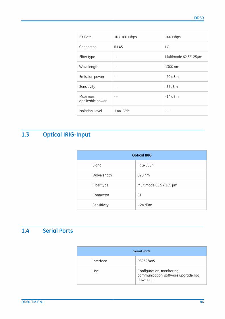
DR60
DR60-TM-EN-1 96
Bit Rate 10 / 100 Mbps 100 Mbps
Connector RJ 45 LC
Fiber type --- Multimode 62,5/125µm
Wavelength --- 1300 nm
Emission power --- -20 dBm
Sensitivity --- -32dBm
Maximum applicable power
--- -14 dBm
Isolation Level 1.44 kVdc ---
1.3 Optical IRIG-Input
Optical IRIG
Signal IRIG-B004
Wavelength 820 nm
Fiber type Multimode 62.5 / 125 µm
Connector ST
Sensitivity - 24 dBm
1.4 Serial Ports
Serial Ports
Interface RS232/485
Use Configuration, monitoring, communication, software upgrade, log download

DR60
DR60-TM-EN-1 97
Bitrate 1200, 2400, 4800, 9600, 19200, 38400 bps
Databits 7 or 8
Stopbits 1 or 2
Parity None, even, odd
Connector DB9 (female), standard DTE
Isolation Level 1.44 KVdc
1.5 Dry-contact Relay Outputs
IN SERVICE contact
Description Dry contact relay, normally closed
Switching Voltage 250 V ( AC and DC)
Permissible current continuous 5 A
Maximum voltage 300 (AC and DC)
Making Capacity 15 A, 4 sec
Breaking Capacity 40W Resistive, 25 W/VA L/R = 50
Dropout time < 5 ms
Burden ~50mA @12V [600mW]
Withstand voltages across open
contacts
1000V rms
Permissible short time value for 1s 30A
1.6 Analog Acquisition

DR60
DR60-TM-EN-1 98
Analog Acquisition
Resolution 16 bits
Frequency measurement range 15 Hz to 70 Hz
System Frequency Bandwidth
50 Hz DC to 3150 Hz
60 Hz DC to 3780 Hz
1.7 Voltage Inputs
Voltage inputs specifications (50/60 Hz)
Characteristic Standard Input High Accuracy Inputs
Nominal Voltage (𝑉𝑛 ) 115 V 115V
Voltage range RMS 0.25-460 V 0.11-230 V
Analog Input Accuracy Class 0.5 (IEC 61869-2)
<0,1% of full scale
Class 0.1 (IEC 61869-2)
<0,1% of full scale
Impedance > 210 kΩ > 420 kΩ
Burden Vn < 0.1 VA < 0.1 VA
Continuous Overload 230 V (2 x 𝑉𝑛 ) 230 V (2 x 𝑉𝑛 )
Maximum Overload (1 s) 460 V (4 x 𝑉𝑛 ) 460 V (4 x 𝑉𝑛 )
Input Isolation >3,5 kV >3,5 kV
1.8 Current Inputs

DR60
DR60-TM-EN-1 99
Current inputs (50/60Hz)
Characteristic Standard Input (P1)
Standard Input (P5)
High Accuracy Inputs (ME)
Nominal Current
(𝐼𝑛 ) 1 A 5 A 1 and 5 A
Current range 0.02… 40 A (40In) 0.1… 200 A (40In) 0.005… 10 A
Analog Input Accuracy
Class 0.5 (IEC 61869-2)¹
0,05In to 40In better than 0,1% ± 2mA
<0,1% of full scale
Class 0.5 (IEC 61869-2)¹
0,05In to 0,2In
better than 0,15%
± 5mA
0,2In to 0,5In
better than 0,1%
± 2mA of
measurement
0,5In to 40In better than 0,1% of measurement
<0,1% of full scale
Class 0.1 (IEC 61869-2)¹
0,05In to 40In better than 0,1% ± 1mA
<0,1% of full scale
Resistance 7,5 mΩ 1,5 mΩ 15 mΩ
Burden In < 0.02 VA < 0.05 VA < 0.02 VA
Continuous overload (rms)
4 A (4 x 𝐼𝑛 ) 20 A (4 x 𝐼𝑛 ) 16 A
AC current thermal withstand (Ith rms for 5 sec)
20x𝐼𝑛 20x𝐼𝑛 20x𝐼𝑛
AC current thermal withstand (Ith rms for 1 sec)
100 A (100 x 𝐼𝑛 ) 320 A (64 x 𝐼𝑛 ) 20 A
Input Isolation >3,5 kV >3,5 kV >3,5 kV
¹ - Gauging performed using waveform measurement

DR60
DR60-TM-EN-1 100
1.9 DC Transducer Inputs
DC Transducer inputs specifications
Characteristic Voltage transducer input Current transducer input
Measurement range
- 12,5 to + 12,5 V 0 to 25 mA
Accuracy ± 0.1 % of FS magnitude range
± 1 % of FS magnitude range
Impedance > 5 kΩ 10 Ω
1.10 Environmental Conditions
Environmental Conditions
Operating temperature range - 40 … +55 °C (–40°F to +131°F)
Maximum operating altitude 2000 m (6560 ft)
Relative humidity 5 … 95 %, noncondensing
As tested per 60068-2-1 -40°C
As tested per 60068-2-2 +55°C
Enclosure Protection IEC 60529 IP20
1.11 Type Tests DR60 EMC tests were performed according to IEC 60255-26 referring to the following
standards
Type Tests DR60
Test Standard Level
Electrostatic discharge
IEC 61000-4-2:2008
6kV contact / 8KV air (level 3)
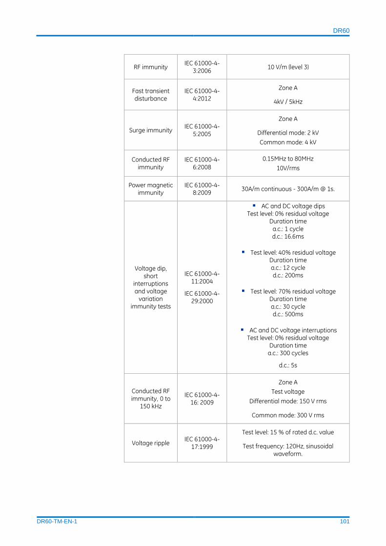
DR60
DR60-TM-EN-1 101
RF immunity IEC 61000-4-
3:2006 10 V/m (level 3)
Fast transient disturbance
IEC 61000-4-4:2012
Zone A
4kV / 5kHz
Surge immunity IEC 61000-4-
5:2005
Zone A
Differential mode: 2 kV
Common mode: 4 kV
Conducted RF immunity
IEC 61000-4-6:2008
0.15MHz to 80MHz
10V/rms
Power magnetic immunity
IEC 61000-4-8:2009
30A/m continuous - 300A/m @ 1s.
Voltage dip, short
interruptions and voltage
variation immunity tests
IEC 61000-4-11:2004
IEC 61000-4-29:2000
AC and DC voltage dips Test level: 0% residual voltage
Duration time a.c.: 1 cycle d.c.: 16.6ms
Test level: 40% residual voltage Duration time a.c.: 12 cycle d.c.: 200ms
Test level: 70% residual voltage Duration time a.c.: 30 cycle d.c.: 500ms
AC and DC voltage interruptions Test level: 0% residual voltage
Duration time a.c.: 300 cycles
d.c.: 5s
Conducted RF immunity, 0 to
150 kHz
IEC 61000-4-16: 2009
Zone A
Test voltage
Differential mode: 150 V rms
Common mode: 300 V rms
Voltage ripple IEC 61000-4-
17:1999
Test level: 15 % of rated d.c. value
Test frequency: 120Hz, sinusoidal waveform.

DR60
DR60-TM-EN-1 102
Damped oscillatory wave
immunity test
IEC 61000-4-18:2006
Voltage oscillation frequency: 1MHz
Differential mode: 1kV peak voltage;
Common mode 2,5kV peak voltage
--- Gradual Startup
Shut-down ramp: 60s
Power off: 5m
Start-up ramp: 60s
Radio-frequency disturbance
CISPR11:2009
Radiated emission below 1GHz
class A
30 MHz to 230 MHz
40 dB(µV/m) quasi peak at 10 m
230 MHz to 1 000 MHz
47 dB(µV/m) quasi peak at 10 m
Radio disturbance
CISPR22:2008
Radiated emission above 1GHz
1 GHz to 3 GHz
56 dB(µV/m) Average
76 dB (µV/m) peak at 3m
3 GHz to 6 GHz
60 dB(µV/m) Average
80 dB (µV/m) peak at 3m
Conducted emission
Class A
0,15 MHz to 0,50 MHz
79 dB(µV) quasi peak
66 dB(µV) average
0,5 MHz to 30 MHz
73 dB(µV) quasi peak
60 dB(µV) average
1.12 Safety Tests

DR60
DR60-TM-EN-1 103
Safety tests
Safety IEC 60255-27:2014
IEC 60255-5 Inpulse - 5KV
Dielectric withstand - 3,3KVDC for 60 seconds
Insulation > 100M Ω
1.13 Environmental tests
Environmental tests
Cold IEC 60068-2-1
-40°C, 16 hours
Dry heat IEC 60068-2-2
+55°C, 16 hours
Damp heat IEC 60068-2-30
95% no condensation, 55°C (Damp heat)
Change of temperature
IEC 60068-2-14
-40°C to 55ºC / 9 hours / 2 cycles
Vibration IEC 60255-21-1
Class 2
Shock IEC 60255-21-2
Class 1
1.14 Dimensions
Dimensions of the equipment
Height 222 mm / 8.7 in (5 U)
Width 222 mm / 8.7 in (½ 19'')
Depth 121 mm / 4.7 in
Weight < 3.5 kg (< 7.72 lb)

DR60
DR60-TM-EN-1 104
DR60 dimensions are shown on the figure below.
DR60 Dimensions

DR60
DR60-TM-EN-1 105
DR60
Digital Recorder
Chapter 10: Wiring Diagrams
This chapter contains the all the possible wiring diagrams for the analogue inputs.
For further details on the inputs, refer to Installation Chapter
1 Connection Diagrams of the Voltage Inputs The DR60 provides the capability for making some different voltage signal
connections for a 3-phase circuit:
Connection diagram of the voltage inputs
4-element connection: in this
case, the values shown are equivalent to the voltages of phases A, B and C, and to the neutral voltage applied to the equipment.
3-element (Phases A, B and C) connection: in this case, the fourth element is derived of the values measured by the other elements. The three elements are equivalent to the values applied to the equipment
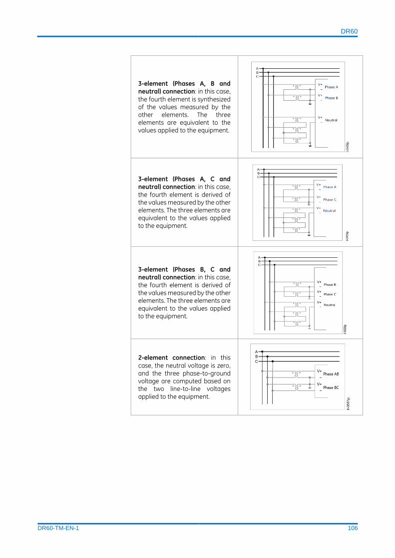
DR60
DR60-TM-EN-1 106
3-element (Phases A, B and neutral) connection: in this case,
the fourth element is synthesized of the values measured by the other elements. The three elements are equivalent to the values applied to the equipment.
3-element (Phases A, C and neutral) connection: in this case, the fourth element is derived of the values measured by the other elements. The three elements are equivalent to the values applied to the equipment.
3-element (Phases B, C and neutral) connection: in this case, the fourth element is derived of the values measured by the other elements. The three elements are equivalent to the values applied to the equipment.
2-element connection: in this
case, the neutral voltage is zero, and the three phase-to-ground voltage are computed based on the two line-to-line voltages applied to the equipment.

DR60
DR60-TM-EN-1 107
Connection diagram for 1 voltage element connection
1-element connection:
Connection diagram of 1 element (phase A, B or C).
1-element connection:
Connection diagram of 1 element (neutral).
2 Connection Diagrams of the Current Inputs
The DR60 provides the capability for connecting some different current signal
connections for a 3-phase circuit:
Connection diagram of the current inputs
4-element connection: in this
case, the values shown are equivalent to the voltages of phases A, B and C, and to the neutral voltage applied to the equipment.
3-element (Phases A, B and C) connection: in this case, the fourth element is derived of the values measured by the other elements. The three elements are equivalent to the values applied to the equipment
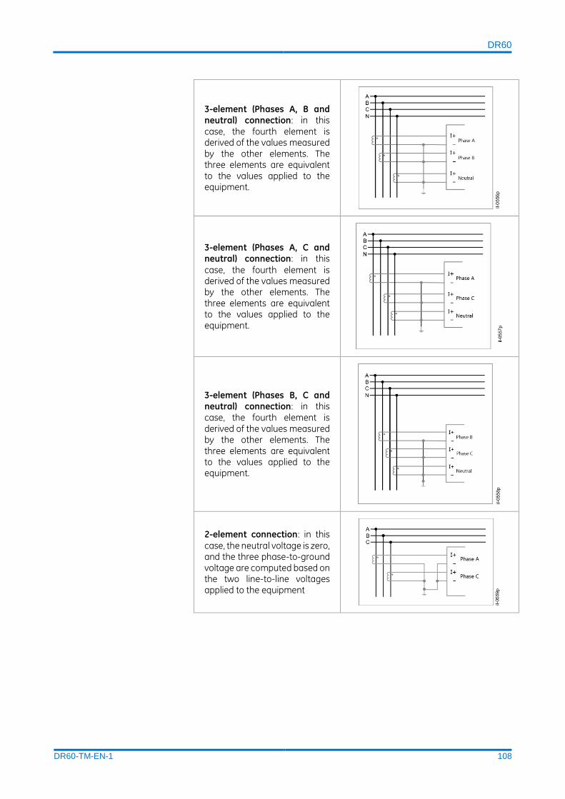
DR60
DR60-TM-EN-1 108
3-element (Phases A, B and neutral) connection: in this case, the fourth element is derived of the values measured by the other elements. The three elements are equivalent to the values applied to the equipment.
3-element (Phases A, C and neutral) connection: in this
case, the fourth element is derived of the values measured by the other elements. The three elements are equivalent to the values applied to the equipment.
3-element (Phases B, C and neutral) connection: in this case, the fourth element is derived of the values measured by the other elements. The three elements are equivalent to the values applied to the equipment.
2-element connection: in this
case, the neutral voltage is zero, and the three phase-to-ground voltage are computed based on the two line-to-line voltages applied to the equipment
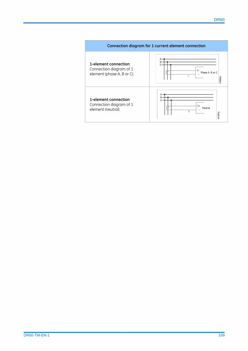
DR60
DR60-TM-EN-1 109
Connection diagram for 1 current element connection
1-element connection:
Connection diagram of 1 element (phase A, B or C).
1-element connection:
Connection diagram of 1 element (neutral).

Appendix A – Equipment Log DR60
DR60-TM-EN-1 110
DR60
Digital Recorder
Appendix A – Equipment Log
1 Equipment Log The equipment log contains information about:
Threshold violations, fault and disturbance triggers and data recording;
Data record transfer (including the IP address to which data has been
transferred);
Access to the unit's configuration pages (including IP address of which the
access was performed);
Alarms and the results of auto-diagnosis routines;
Power-up and shutdown.
The equipment log cannot be erased by the user. Its capacity is enough for
approximately 5 years of typical use, with past events being erased if memory space
is needed.
Code Message
LX01 First Installation
LX02 Applied new settings to IED
LX03 Restored last valid settings
LX04 Downloaded settings from IED
LX05 Downloaded support file from IED
LX06 Downloaded user event logs from IED
LX07 Physical Health changed to ?, cause: ?
LX08 Software upgraded from ? to ?:
LX09 Applied new license to IED
LX10 Card failure: slot ?
LX11 Internal voltage: expected ? V, measured ? V, condition: ?
LX12 Temperature: ? ºC, condition: ?
LX13 Returned internal image to ?
LX14 Power up
LC01 Ethernet link status
LC02 Ethernet port settings changed to IP: ?, submask: ?, gateway: ?
LC03 Serial port settings changed to speed: ? bps, data bits: ?, parity: ?, stop bits: ?
LC04 GOOSE Timeout
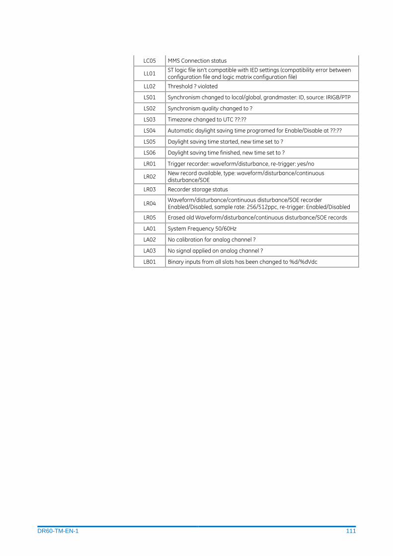
DR60-TM-EN-1 111
LC05 MMS Connection status
LL01 ST logic file isn't compatible with IED settings (compatibility error between configuration file and logic matrix configuration file)
LL02 Threshold ? violated
LS01 Synchronism changed to local/global, grandmaster: ID, source: IRIGB/PTP
LS02 Synchronism quality changed to ?
LS03 Timezone changed to UTC ??:??
LS04 Automatic daylight saving time programed for Enable/Disable at ??:??
LS05 Daylight saving time started, new time set to ?
LS06 Daylight saving time finished, new time set to ?
LR01 Trigger recorder: waveform/disturbance, re-trigger: yes/no
LR02 New record available, type: waveform/disturbance/continuous disturbance/SOE
LR03 Recorder storage status
LR04 Waveform/disturbance/continuous disturbance/SOE recorder Enabled/Disabled, sample rate: 256/512ppc, re-trigger: Enabled/Disabled
LR05 Erased old Waveform/disturbance/continuous disturbance/SOE records
LA01 System Frequency 50/60Hz
LA02 No calibration for analog channel ?
LA03 No signal applied on analog channel ?
LB01 Binary inputs from all slots has been changed to %d/%dVdc