DIGITAL MULTIMETER KM 857 - Kusam Electricalkusamelectrical.com/manual/High Safety UL...
21
Digital Multimeter Digital AC & AC/DC Clampmeter AC Clamp Adaptor AC/DC Current Adaptor Transistorised Electronic Analog & Digital Insulation Resistance Testers(upto 10 KV) Digital Sound Level Meter & Sound Level Calibrator Digital contact & Non-contact Type Tachometer Digital Non-contact (infrared) Thermometer Thermo Hygrometer Thermo Anemometer Wood & Paper Moisture Meter Distance Meter Digital Hand Held Temperature Indicators Digital Lux Meter Network Cable Tester Power Factor Regulator Maximum Demand Controller/Digital Power Meter Earth Resistance Tester Gas Analysers Panel Meters Battery Testers DC Power Supply Vehicle Tracking System LIST OF PRODUCTS * * * * * * * * * * * * * * * * * * * * * * * OPERATION MANUAL DIGITAL MULTIMETER KM 857 / KM 859CF ® AN ISO 9001:2008 COMPANY
Transcript of DIGITAL MULTIMETER KM 857 - Kusam Electricalkusamelectrical.com/manual/High Safety UL...
Digital Multimeter
Digital AC & AC/DC Clampmeter
AC Clamp Adaptor
AC/DC Current Adaptor
Transistorised Electronic Analog & Digital
Insulation Resistance Testers(upto 10 KV)
Digital Sound Level Meter & Sound Level
Calibrator
Digital contact & Non-contact Type
Tachometer
Digital Non-contact (infrared) Thermometer
Thermo Hygrometer
Thermo Anemometer
Wood & Paper Moisture Meter
Distance Meter
Digital Hand Held Temperature Indicators
Digital Lux Meter
Network Cable Tester
Power Factor Regulator
Maximum Demand Controller/Digital Power
Meter
Earth Resistance Tester
Gas Analysers
Panel Meters
Battery Testers
DC Power Supply
Vehicle Tracking System
LIST OF PRODUCTS
**********
*
*
*****
******
OPERATIONMANUAL
DIGITALMULTIMETER
KM 857 / KM 859CF
®®
AN ISO 9001:2008 COMPANY
DIGITAL MULTIMETER
KM 857KM 859CF
we damage them or “burn them out”. If you incorrectly
TAKE MEASUREMENTS CAREFULLY AND YOU’LLSPARE YOUR METER AND YOURSELF, SOME PAIN
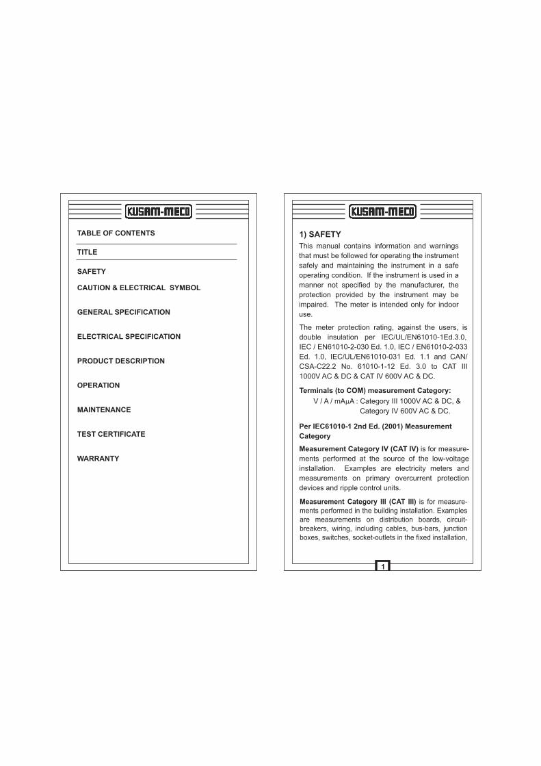
TABLE OF CONTENTS
TITLE
SAFETY
CAUTION & ELECTRICAL SYMBOL
GENERAL SPECIFICATION
ELECTRICAL SPECIFICATION
PRODUCT DESCRIPTION
OPERATION
MAINTENANCE
TEST CERTIFICATE
WARRANTY
Per IEC61010-1 2nd Ed. (2001) Measurement
Category
1) SAFETY
The meter protection rating, against the users, is
double insulation per IEC/UL/EN61010-1Ed.3.0,
IEC / EN61010-2-030 Ed. 1.0, IEC / EN61010-2-033
Ed. 1.0, IEC/UL/EN61010-031 Ed. 1.1 and CAN/
CSA-C22.2 No. 61010-1-12 Ed. 3.0 to CAT III
1000V AC & DC & CAT IV 600V AC & DC.
This manual contains information and warnings
that must be followed for operating the instrument
safely and maintaining the instrument in a safe
operating condition. If the instrument is used in a
manner not specified by the manufacturer, the
protection provided by the instrument may be
impaired. The meter is intended only for indoor
use.
Terminals (to COM) measurement Category:
V / A / mAmA : Category III 1000V AC & DC, &
Category IV 600V AC & DC.
Measurement Category IV (CAT IV) is for measure-
ments performed at the source of the low-voltage
installation. Examples are electricity meters and
measurements on primary overcurrent protection
devices and ripple control units.
1
Measurement Category III (CAT III) is for measure-ments performed in the building installation. Examples are measurements on distribution boards, circuit-breakers, wiring, including cables, bus-bars, junction boxes, switches, socket-outlets in the fixed installation,
Suspected open circuit voltage should be checked with voltage functions.
Never attempt a voltage measurement with the test
lead inserted into the mA/mA or A input jack.
Only replace the blown fuse with the proper rating as specified in this manual. Only use the test leadprovided with the equipment or UL listed Probe assembly rated CAT III 1000V or better.
Disconnect the test leads from the test points before changing functions. Always set the instrument to the hightest range and work downward for an unknown value when using manual ranging mode.
CAUTION
~
!
INTERNATIONAL ELECTRICAL SYMBOLS
Caution ! Refer to the explanation in this Manual
Caution ! Risk of electric shock
Earth (Ground)
Double Insulation or Reinforced insulation
Fuse
AC--Alternating Current
DC--Direct Current
2) CENELEC Directives
The instruments conform to CENELEC Low-voltage directive 2006/95/EC and Electromagnetic compatibility directive 2004/108/EC
3
and equipment for industrial use and some other equipment, for example, stationary motors with permanent connection to the fixed installation.
Measurement Category II (CAT II) is for measure-ments performed on circuits directly connected to the low voltage installation. Examples are measure-ments on household appliances, portable tools andsimilar equipment.
To reduce the risk of fire or electric shock, do not expose this product to rain or moisture. To avoid electrical shock hazard, observe the proper safety precautions when working with voltages above 60VDC or 30 VAC rms. These voltage levels pose a potential shock hazard to the user.
TERMS IN THIS MANUAL
WARNING identifies conditions and actions that
could result in serious injury or even death to the user.
CAUTION identifies conditions and actions that
could cause damage or malfunction in the instrument.
WARNING
Do not touch test lead tips or the circuit being testedwhile power is applied to the circuit being measured.
Keep your fingers behind the finger guards of thetest leads during measurement.
Inspect test leads, connectors, and probes for damaged insulation or exposed metal before usingthe instrument. If any defects are found, replace them immediately.
2
Do not measure any current that exceeds the current rating of the protection fuse. Do not attempt a currentmeasurement to any circuit where the open circuit voltage is above the protection fuse voltage rating.
Overload Protections :
mA & mA : 0.44A/1000V DC/AC rms, IR10kA, F Fuse
A : 11A/1000V DC/AC rms, IR 20kA, F Fuse
V : 1100V DC/AC rms
mV, W & Others :1000V DC/AC rms
Transient Protection : 8kV (1.2/50mS surge)
E.M.C.: Meets EN61326-1:2006 (EN55022,
EN61000-3-2, EN61000-3-3, EN61000-4-2,
EN61000-4-3, EN61000-4-4, EN61000-4-5,
EN61000-4-6, EN61000-4-8,EN61000-4-11)
In an RF field of 3V/m.
Capacitance function is not specified
Other function ranges :
Total Accuracy=Specified Accuracy+100 digits
Performance above 3V/m is not specified.
Power Supply : Single 9V battery.
Power Consumption : 6mA typical
Low Battery : Below approx. 7V
APO Timing : Idle for 17 minutes
APO Consumption : 55mA typical for (KM 857)
30mA typical for (KM859CF)
Dimension : 186(L) x 87(W) x 35.5(H)mm
198(L)x97(W)x55(H)mm with holster
Weight : 390gm; 500gm with holster.
Accessories : Test leads(pair), Holster, Battery
installed, user Manual, Bkp60 banana plug K-type
Thermocouple x 1(KM 859CF).
5
Display: 4-4/5 digits 50,000 counts. Selectable
stable mode 5-4/5 digits 500,000 counts
for DC Voltage, & 6 digits 999,999 counts
for Hz
Polarity : Automatic
Update Rate:
4-4/5 digits fast mode : 5 per second nominal;
5-4/5 digits stable mode : 1.25 per second nominal;
42 Segments Bar graph : 60 per second maxo
Operating Temperature : 0 C to 45 C
Relative Humidity : Max. relative humidity 80% for o temperature up to 31 C
decreasing linearly to 50% o relative humidity at 45 C
Pollution degree : 2o oStorage Temperature : -20 C to 60 C, < 80%R.H.
(with battery removed)
Altitude : Operating below 2000m
Temperature Coefficient : nominal 0.1 x
(specified accuracy)/o o o o o C@(0 C -- 18 C or 28 C -- 40 C),
or otherwise specified.
Sensing : AC, AC + DC True RMS
Safety : Double insulation per IEC/UL/EN61010-1
Ed.3.0, IEC/EN61010-2-030 Ed.1.0, IEC/EN61010-
2-033 Ed. 1.0, IEC/UL/EN61010-031 Ed. 1.1 and
CAN/CSA-C22.2 No. 61010-1-12 Ed. 3.0 to
CAT III 1000V AC & DC & CAT IV 600V AC & DC.
o
3) GENERAL SPECIFICATIONS
Terminals (to COM) measurement category:
V/A/mAmA : Category III 1000V AC & DC, & Category IV 600V AC & DC.
4
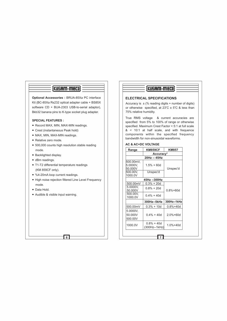
SPECIAL FEATURES :
Record MAX, MIN, MAX-MIN readings.
Crest (instantaneous Peak hold)
MAX, MIN, MAX-MIN readings.
Relative zero mode.
500,000 counts high resolution stable reading
mode.
Backlighted display.
dBm readings.
T1-T2 differential temperature readings
(KM 859CF only).
%4-20mA loop current readings.
High noise rejection filtered Line Level Frequency
mode.
Data Hold.
Audible & visible input warning.
—
—
—
—
—
—
—
—
—
—
—
—
Optional Accessories : BRUA-85Xa PC interface
Kit (BC-85Xa Rs232 optical adapter cable + BS85X
software CD + BUA-2303 USB-to-serial adaptor),
Bkb32 banana pins to K-type socket plug adapter.
6
AC & AC+DC VOLTAGE
Range KM859CF KM857
Accuracy*
20Hz -- 45Hz
500.00mV,5.0000V, 1.5% + 60d50.000V Unspec'd500.00V, Unspec'd1000.0V
500.00mV 0.3% + 20d5.0000V, 0.8% + 20d50.000V 0.8%+60d500.00V,
0.4% + 40d1000.0V
45Hz --300Hz
ELECTRICAL SPECIFICATIONS
Accuracy is ± (% reading digits + number of digits) o o
or otherwise specified, at 23 C ± 5 C & less than
75% relative humidity.
True RMS voltage & current accuracies are
specified from 5% to 100% of range or otherwise
specified. Maximum Crest Factor < 5:1 at full scale
& < 10:1 at half scale, and with frequence
components within the specified frequency
bandwidth for non-sinusoidal waveforms.
500.00mV 0.3% + 10d 0.8%+40d
5.0000V,
50.000V 0.4% + 40d 2.0%+60d
500.00V
1000.0V 0.8% + 40d
1.0%+40d (300Hz--1kHz)
300Hz--5kHz
7
300Hz--1kHz
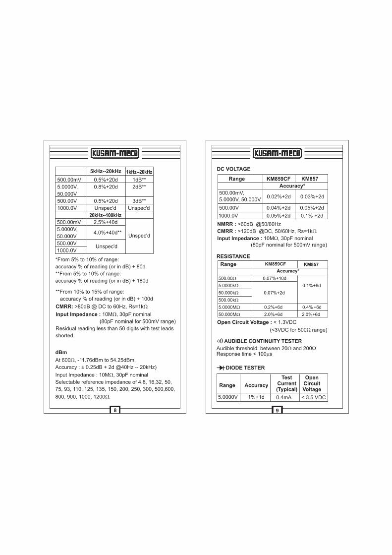
**From 10% to 15% of range:
accuracy % of reading (or in dB) + 100d
CMRR: >80dB @ DC to 60Hz, Rs=1kW
Input Impedance : 10MW, 30pF nominal
(80pF nominal for 500mV range)
Residual reading less than 50 digits with test leads
shorted.
*From 5% to 10% of range:
accuracy % of reading (or in dB) + 80d
**From 5% to 10% of range:
accuracy % of reading (or in dB) + 180d
500.00mV 0.5%+20d 1dB**
5.0000V, 0.8%+20d 2dB**
50.000V
500.00V 0.5%+20d 3dB**
1000.0V Unspec'd Unspec'd
20kHz--100kHz
500.00mV 2.5%+40d
5.0000V, 4.0%+40d**
50.000V Unspec'd
500.00V Unspec'd
1000.0V
5kHz--20kHz
dBm
At 600 , -11.76dBm to 54.25dBm,
Accuracy : ± 0.25dB + 2d @40Hz -- 20kHz)
Input Impedance : 10MW, 30pF nominal
Selectable reference impedance of 4,8, 16,32, 50,
75, 93, 110, 125, 135, 150, 200, 250, 300, 500,600,
800, 900, 1000, 1200W.
W
8
1kHz--20kHz
RESISTANCE
Open Circuit Voltage : < 1.3VDC
(<3VDC for 500W range)
Range KM859CF KM857
Accuracy*
500.00 W 0.07%+10d
5.0000k W 0.1%+6d
50.000k W 0.07%+2d
500.00kW
5.0000M W 0.2%+6d 0.4% +6d
50.000M W 2.0%+6d 2.0%+6d
DC VOLTAGE
Range KM859CF KM857
Accuracy*
500.00mV, 0.02%+2d 0.03%+2d
5.0000V, 50.000V
500.00V 0.04%+2d 0.05%+2d
1000.0V 0.05%+2d 0.1% +2d
NMRR : >60dB @50/60Hz
CMRR : >120dB @DC, 50/60Hz, Rs=1kW
Input Impedance : 10MW, 30pF nominal (80pF nominal for 500mV range)
Audible threshold: between 20 and 200 Response time < 100 s
W Wm
AUDIBLE CONTINUITY TESTER)))
DIODE TESTER
Range Accuracy
TestCurrent(Typical)
OpenCircuitVoltage
5.0000V 1%+1d 0.4mA < 3.5 VDC
9
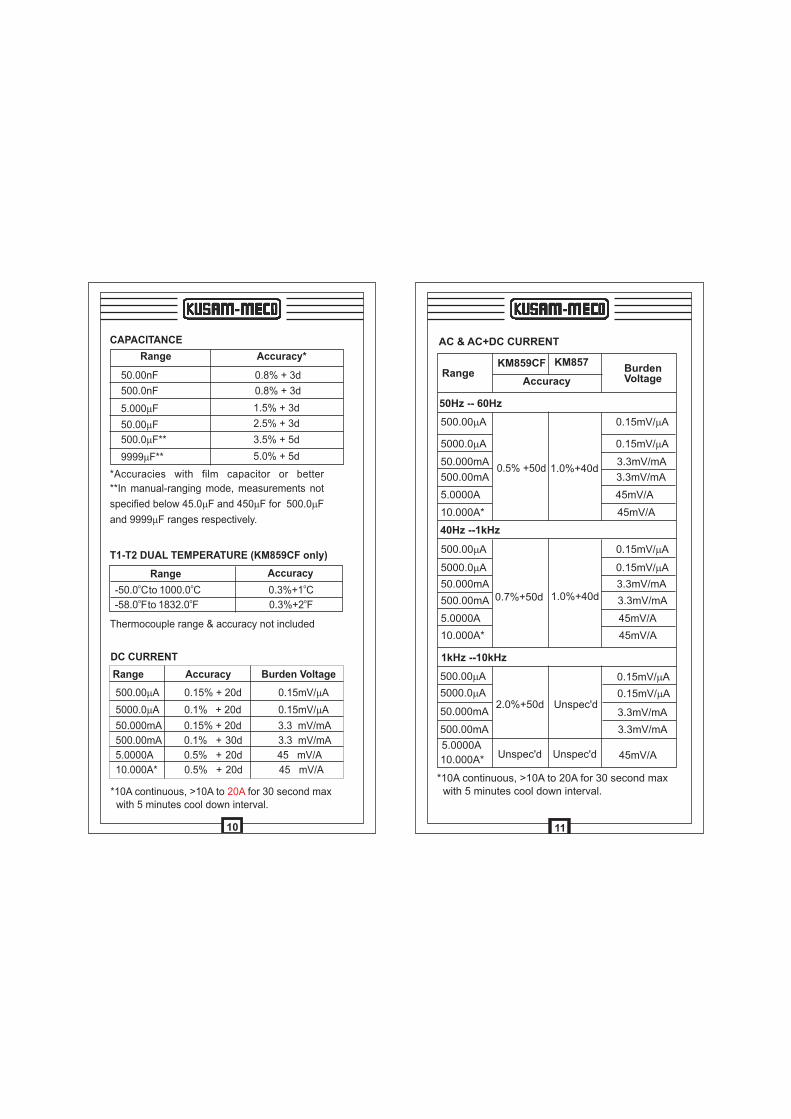
CAPACITANCE
Range Accuracy*
50.00nF 0.8% + 3d
500.0nF 0.8% + 3d
5.000mF 1.5% + 3d
50.00 F m 2.5% + 3d
500.0 F**m 3.5% + 5d
9999 F**m 5.0% + 5d
*Accuracies with film capacitor or better
**In manual-ranging mode, measurements not
specified below 45.0mF and 450 F for 500.0 F
and 9999mF ranges respectively.
m m
T1-T2 DUAL TEMPERATURE (KM859CF only)
o-50.0 C to o1000.0 C o0.3%+1 C
o-58.0 F to
o1832.0 F
o0.3%+2 F
Thermocouple range & accuracy not included
Range Accuracy
DC CURRENT
Range Accuracy Burden Voltage
500.00 A m 0.15% + 20d 0.15mV/ Am
5000.0 A m 0.1% + 20d 0.15mV/ Am
50.000mA 0.15% + 20d 3.3 mV/mA
500.00mA 0.1% + 30d 3.3 mV/mA
5.0000A 0.5% + 20d 45 mV/A
10.000A* 0.5% + 20d 45 mV/A
*10A continuous, >10A to for 30 second max with 5 minutes cool down interval.
20A
10
AC & AC+DC CURRENT
RangeKM859CF KM857
Accuracy
50Hz -- 60Hz
500.00mA 0.15mV/ Am
5000.0 A 0.15mV/ Am m
50.000mA 0.5% +50d 1.0%+40d
3.3mV/mA
500.00mA 3.3mV/mA
5.0000A 45mV/A
10.000A* 45mV/A
40Hz --1kHz
BurdenVoltage
500.00mA 0.15mV/ Am
5000.0 A 0.15mV/ Am m
50.000mA 0.7%+50d 1.0%+40d
3.3mV/mA
500.00mA 3.3mV/mA
5.0000A 45mV/A
10.000A* 45mV/A
1kHz --10kHz
500.00mA 0.15mV/ Am
5000.0 A m2.0%+50d Unspec'd
0.15mV/ Am
50.000mA 3.3mV/mA
500.00mA 3.3mV/mA
5.0000A
10.000A*
*10A continuous, >10A to 20A for 30 second max with 5 minutes cool down interval.
Unspec'd Unspec'd 45mV/A
11
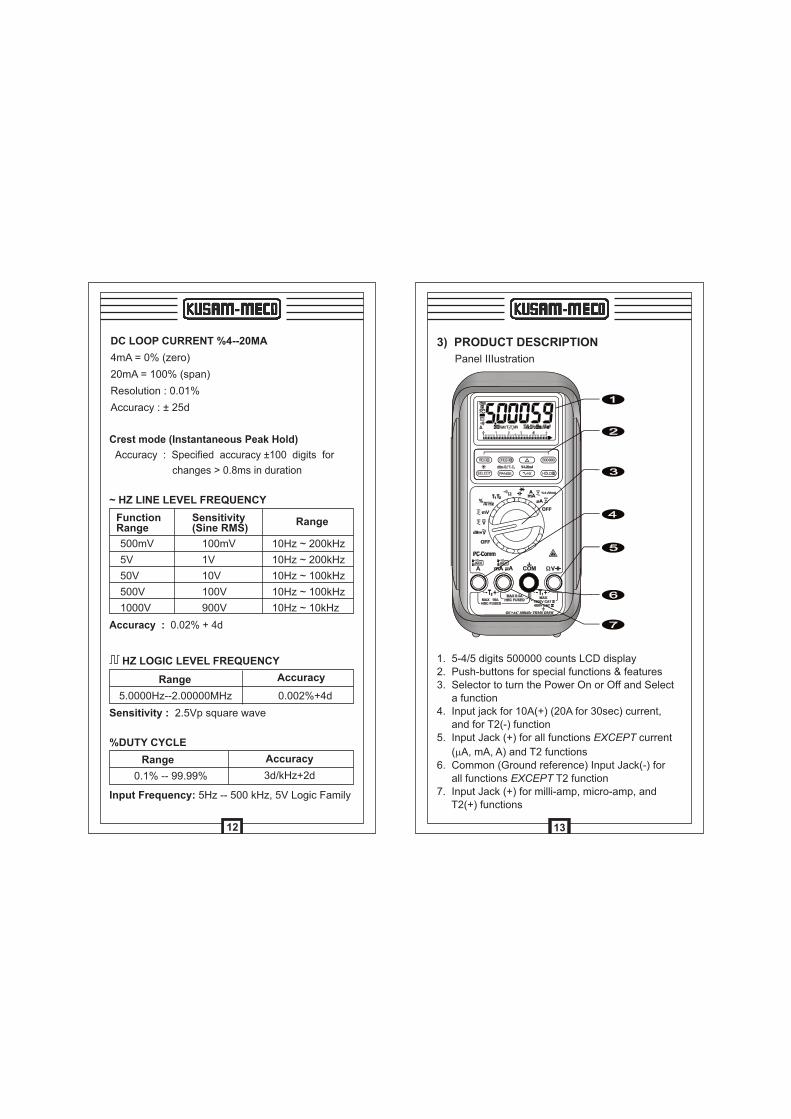
500mV
5V
50V
500V
1000V
Range
Range
0.1% -- 99.99% 3d/kHz+2d
Accuracy
%DUTY CYCLE
Input Frequency: 5Hz -- 500 kHz, 5V Logic Family
Range
5.0000Hz--2.00000MHz 0.002%+4d
Accuracy
HZ LOGIC LEVEL FREQUENCY
Sensitivity : 2.5Vp square wave
Crest mode (Instantaneous Peak Hold)
Accuracy : Specified accuracy ±100 digits for
changes > 0.8ms in duration
DC LOOP CURRENT %4--20MA
4mA = 0% (zero)
20mA = 100% (span)
Resolution : 0.01%
Accuracy : ± 25d
~ HZ LINE LEVEL FREQUENCY
FunctionRange
Sensitivity(Sine RMS)
100mV
1V
10V
100V
900V
10Hz ~ 200kHz
10Hz ~ 200kHz
10Hz ~ 100kHz
10Hz ~ 100kHz
10Hz ~ 10kHz
Accuracy : 0.02% + 4d
12
3) PRODUCT DESCRIPTION
Panel IIIustration
1. 5-4/5 digits 500000 counts LCD display2. Push-buttons for special functions & features3. Selector to turn the Power On or Off and Select a function4. Input jack for 10A(+) (20A for 30sec) current, and for T2(-) function5. Input Jack (+) for all functions EXCEPT current
(mA, mA, A) and T2 functions6. Common (Ground reference) Input Jack(-) for all functions EXCEPT T2 function7. Input Jack (+) for milli-amp, micro-amp, and T2(+) functions
13
RMS (Root-Mean-Square) is the term used to
describe the effective or equivalent DC value of an
AC signal. Most digital multimeters use average
sensing RMS calibrated technique to measure RMS
values of AC signals. This technique is to obtain the
average value by rectifying and filtering the AC
signal. The average value is then scaled upward
(calibrated) to read the RMS value of a sine wave.
In measuring pure sinusoidal waveforms, this
technique is fast, accurate, and cost effective.
Inmeasuring non-sinusoidal waveforms, however,
significant errors can be introduced because of
different scaling factors relating average to RMS
values.
Average sensing RMS calibrated
AC True RMS, normally refers as True RMS,
identifies a DMM function that is AC coupled, and
responds accurately only to the effective RMS AC
component value regardless of the waveforms.
However, DC component plays an important role in
the distorted non-symmetrical waveforms, and will
also be of interest sometimes. A full wave rectified
sine waveform is a good example, and the AC true
RMS function will only give the AC component
reading which is at 43.6% of the total effective
DC+AC RMS reading.
AC True RMS
14
DC + AC True RMS calculates both of the AC and
DC components given by the expression 2 2
DC +(AC rms) When making measurement, and
can respond accurately to the total effective RMS
value regardless of the waveform. Distorted
waveforms with the presence of DC components
and harmonics may cause:
DC+AC True RMS
AC bandwidth of a DMM is the range of
frequencies over which AC measurements can
be made within the specified accuracy. It is not
the frequency measurement function, and is the
frequency response of the AC functions. A DMM
cannot accurately measure the AC value with
frequency spectrums beyond the AC bandwidth
of the DMM. Therefore, wide AC bandwidth plays
an important role in high performance DMMs. In
reality, complex waveforms, noise and distorted
waveforms contain much higher frequency
spectrum than its fundamental.
1) Overheated transformers, generators and
motors to burn out faster than normal
2) Circuit breakers to trip prematurely.
3) Fuses to blow
4) Neutrals to overheat due to the triplen
harmonics present on the neutral
5) Bus bars and electrical panels to vibrate
AC Bandwidth
15
Common mode voltage is voltage present on both
the COM and VOLTAGE input terminals of a DMM,
with respect to ground. CMRR is the DMM's ability
to reject common mode voltage effect that can
cause digit rolling or offset in voltage measure-
ments. This series has a CMRR specifications of
> 80dB at DC to 60Hz in ACV function; and
> 120dB at DC, 50 and 60Hz in DCV function. If
neither NMRR nor CMRR specification is specified,
a DMM's performance will be uncertain.
NMRR is the DMM's ability to reject unwanted AC
noise effect that can cause inaccurate DC
measurements. NMRR is typically specified in
terms of dB (decibel). This series has a NMRR
specification of > 60dB at 50 and 60Hz, which is a
good and definite ability to reject the effect of
noise when making DC measurements.
NMRR (Normal Mode Rejection Ratio)
CMRR (Commaon Mode Rejection Ratio)
The analog bar graph provides a visual indication of
measurement like a traditional analog meter
needle. It is excellent in detecting faulty contacts,
identifying potentiometer clicks, and indicating
signal spikes during adjustments. Analog bar-
graph is not available in AC+DC True RMS Voltage
& Current modes.
Analog bar-graph
16
In AC Voltage, press SELECT button momentarily
to toggle between AC and dBm. In DC Voltage,
press SELECT button momentarily to toggle
between DC, and DC+AC. In mV Voltage, press
SELECT button momentarily to select DC, AC, or
DC+AC.The new settings wil l be saved
automatically to the non-volatile memory as
power up default. In DCV and DCmV, press
500000 button momentarily to toggle between
4-4/5 digits and 5-4/5 digits readings. In voltage or
current functions, press the ~Hz push button
momentarily to activate or to exit Line Level
Frequency measuring function. Line Level
Frequency measuring function is designed
especially for noisy electrical high voltage signals.
4) OPERATION
AC Voltage, DC Voltage, DC+AC Voltage, &
~Hz Line Level Frequency
CAUTION
Before and after hazardous voltage measurements,
test the voltage function on a known source such
as line voltage to determine proper meter
functioning.
17
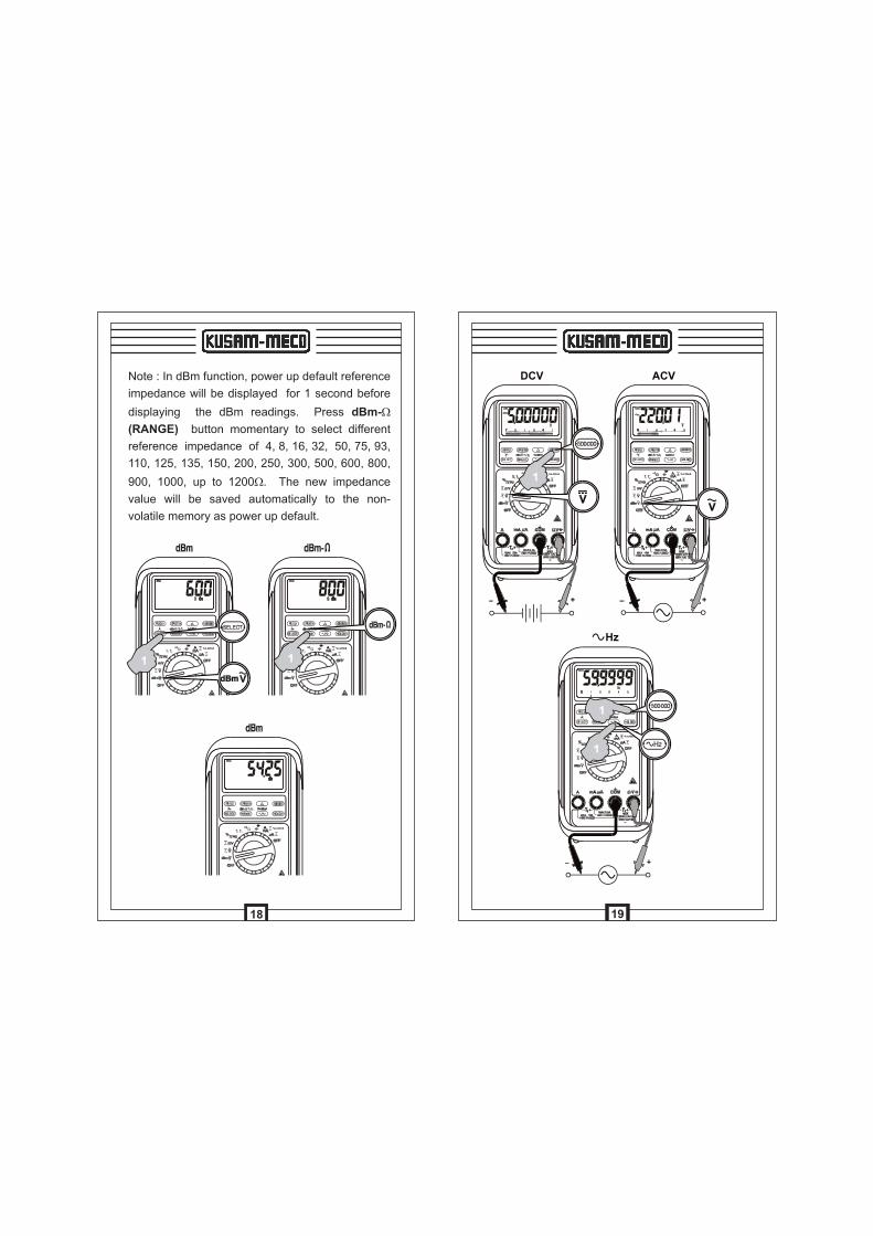
Note : In dBm function, power up default reference
impedance will be displayed for 1 second before
displaying the dBm readings. Press dBm-W
(RANGE) button momentary to select different
reference impedance of 4, 8, 16, 32, 50, 75, 93,
110, 125, 135, 150, 200, 250, 300, 500, 600, 800,
900, 1000, up to 1200W. The new impedance
value will be saved automatically to the non-
volatile memory as power up default.
18
19
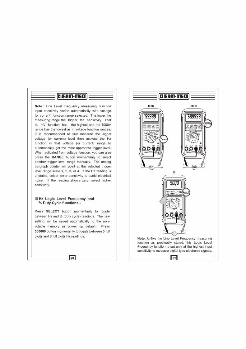
Note : Line Level Frequency measuring function
input sensitivity varies automatically with voltage
(or current) function range selected. The lower the
measuring range the higher the sensitivity. That
is, mV function has the highest and the 1000V
range has the lowest as in voltage function ranges.
It is recommended to first measure the signal
voltage (or current) level then activate the Hz
function in that voltage (or current) range to
automatically get the most approprite trigger level.
When activated from voltage function, you can also
press the RANGE button momentarily to select
another trigger level range manually. The analog
bargraph pointer will point at the selected trigger
level range scale 1, 2, 3, or 4. If the Hz reading is
unstable, select lower sensitivity to avoid electrical
noise. If the reading shows zero, select higher
sensitivity.
Press SELECT button momentarily to toggle
between Hz and % (duty cycle) readings. The new
setting will be saved automatically to the non-
volatile memory as power up default. Press
500000 button momentarily to toggle between 5 full
digits and 6 full digits Hz readings.
Hz Logic Level Frequency and % Duty Cycle functions:-
20
Note: Unlike the Line Level Frequency measuring function as previously stated, this Logic Level Frequency function is set only at the highest input sensitivity to measure digital type electronic signals.
21
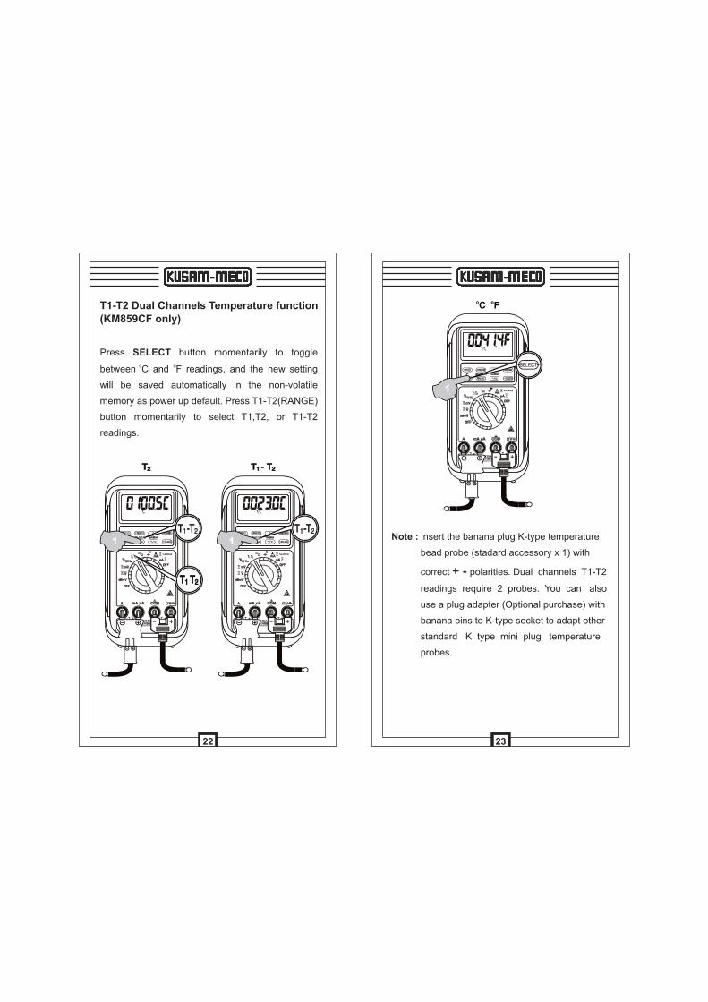
Note : insert the banana plug K-type temperature
bead probe (stadard accessory x 1) with
correct + - polarities. Dual channels T1-T2
readings require 2 probes. You can also
use a plug adapter (Optional purchase) with
banana pins to K-type socket to adapt other
standard K type mini plug temperature
probes.
23
T1-T2 Dual Channels Temperature function (KM859CF only)
Press SELECT button momentarily to toggle o o
between C and F readings, and the new setting
will be saved automatically in the non-volatile
memory as power up default. Press T1-T2(RANGE)
button momentarily to select T1,T2, or T1-T2
readings.
22
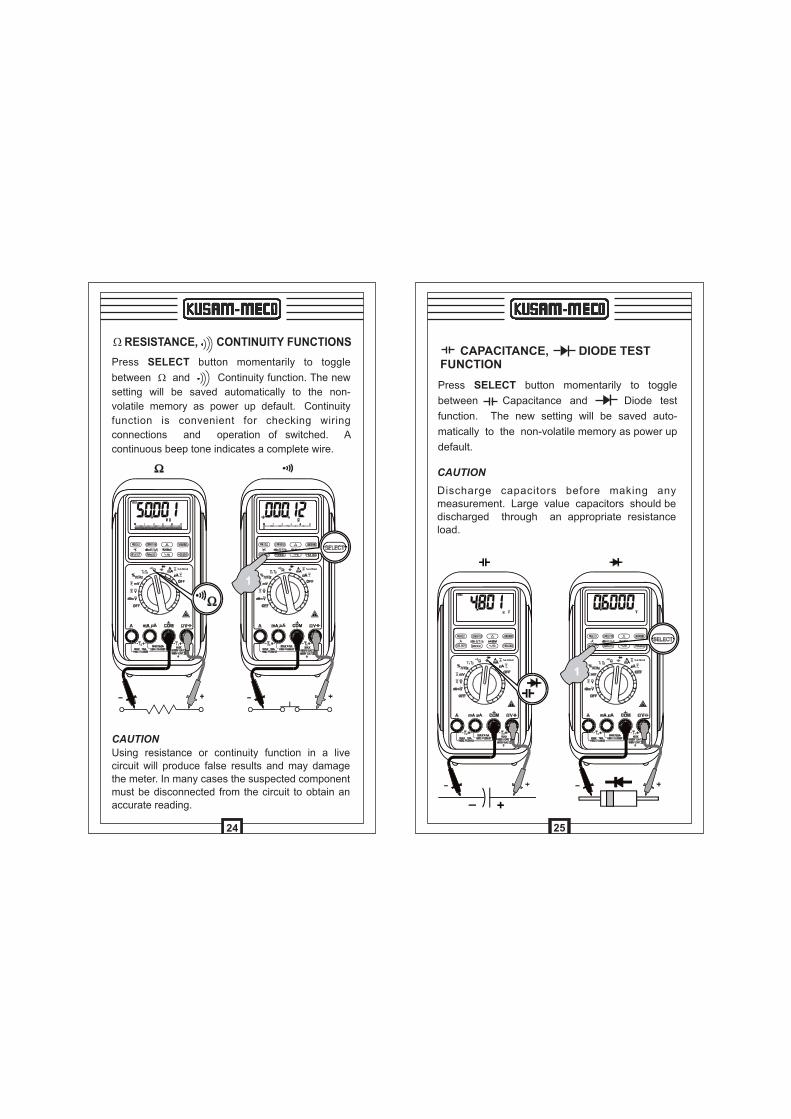
Press SELECT button momentarily to toggle
between W and Continuity function. The new
setting will be saved automatically to the non-
volatile memory as power up default. Continuity
function is convenient for checking wiring
connections and operation of switched. A
continuous beep tone indicates a complete wire.
W RESISTANCE, CONTINUITY FUNCTIONS
Using resistance or continuity function in a live circuit will produce false results and may damage the meter. In many cases the suspected componentmust be disconnected from the circuit to obtain an accurate reading.
CAUTION
24
CAPACITANCE, DIODE TEST FUNCTION
Press SELECT button momentarily to toggle
between Capacitance and Diode test
function. The new setting will be saved auto-
matically to the non-volatile memory as power up
default.
CAUTION
Discharge capacitors before making any measurement. Large value capacitors should be discharged through an appropriate resistance load.
25
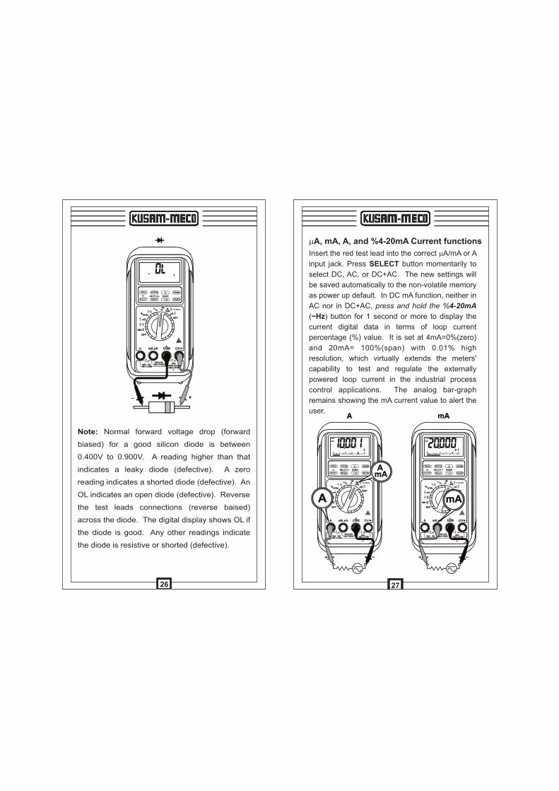
Note: Normal forward voltage drop (forward
biased) for a good silicon diode is between
0.400V to 0.900V. A reading higher than that
indicates a leaky diode (defective). A zero
reading indicates a shorted diode (defective). An
OL indicates an open diode (defective). Reverse
the test leads connections (reverse baised)
across the diode. The digital display shows OL if
the diode is good. Any other readings indicate
the diode is resistive or shorted (defective).
26
Insert the red test lead into the correct mA/mA or A
input jack. Press SELECT button momentarily to
select DC, AC, or DC+AC. The new settings will
be saved automatically to the non-volatile memory
as power up default. In DC mA function, neither in
AC nor in DC+AC, press and hold the %4-20mA
(~Hz) button for 1 second or more to display the
current digital data in terms of loop current
percentage (%) value. It is set at 4mA=0%(zero)
and 20mA= 100%(span) with 0.01% high
resolution, which virtually extends the meters'
capability to test and regulate the externally
powered loop current in the industrial process
control applications. The analog bar-graph
remains showing the mA current value to alert the
user.
mA, mA, A, and %4-20mA Current functions
27
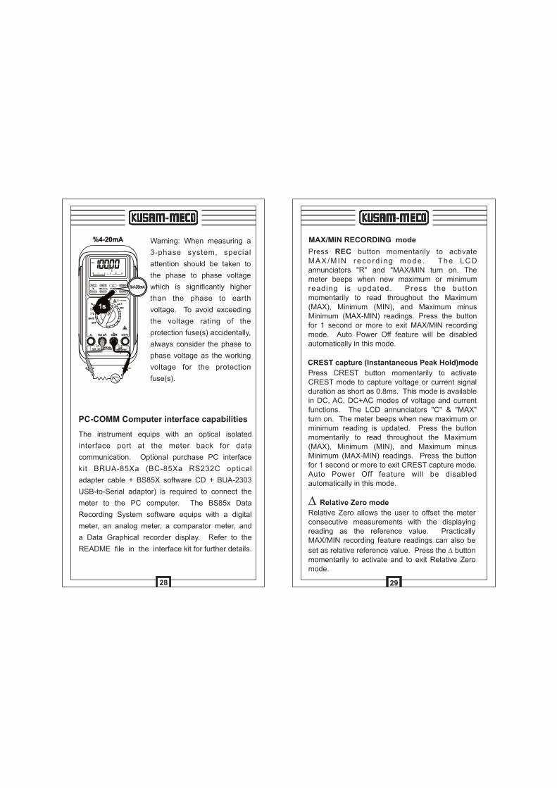
Warning: When measuring a
3-phase system, special
attention should be taken to
the phase to phase voltage
which is significantly higher
than the phase to earth
voltage. To avoid exceeding
the voltage rating of the
protection fuse(s) accidentally,
always consider the phase to
phase voltage as the working
voltage for the protection
fuse(s).
The instrument equips with an optical isolated
interface port at the meter back for data
communication. Optional purchase PC interface
kit BRUA-85Xa (BC-85Xa RS232C optical
adapter cable + BS85X software CD + BUA-2303
USB-to-Serial adaptor) is required to connect the
meter to the PC computer. The BS85x Data
Recording System software equips with a digital
meter, an analog meter, a comparator meter, and
a Data Graphical recorder display. Refer to the
README file in the interface kit for further details.
PC-COMM Computer interface capabilities
28
Press REC button momentarily to activate MAX/MIN reco rd i ng mode . The LCD annunciators "R" and "MAX/MIN turn on. The meter beeps when new maximum or minimum reading is updated. Press the button momentarily to read throughout the Maximum (MAX), Minimum (MIN), and Maximum minus Minimum (MAX-MIN) readings. Press the button for 1 second or more to exit MAX/MIN recording mode. Auto Power Off feature will be disabled automatically in this mode.
MAX/MIN RECORDING mode
Press CREST button momentarily to activate CREST mode to capture voltage or current signal duration as short as 0.8ms. This mode is available in DC, AC, DC+AC modes of voltage and current functions. The LCD annunciators "C" & "MAX" turn on. The meter beeps when new maximum or minimum reading is updated. Press the button momentarily to read throughout the Maximum (MAX), Minimum (MIN), and Maximum minus Minimum (MAX-MIN) readings. Press the button for 1 second or more to exit CREST capture mode. Auto Power Off feature will be disabled automatically in this mode.
CREST capture (Instantaneous Peak Hold)mode
Relative Zero allows the user to offset the meter consecutive measurements with the displaying reading as the reference value. Practically MAX/MIN recording feature readings can also be
set as relative reference value. Press the D button momentarily to activate and to exit Relative Zero mode.
D Relative Zero mode
29
Press the SELECT button for 1 second or more to turn on or off the display backlight function. The backlight will also be turned off automatically after 30 seconds to extend battery life.
In DC voltage and frequency functions, press the 500000 button momentarily to toggle between the 4-4/5 digits fast mode and the 5-4/5 digits high resolution stable mode.
500000 high resolution stable mode
Backlighted display
Manual or Auto-ranging
Press the RANGE button momentarily to select manual-ranging mode, and the meter will remain in the range it was in, the LCD annunciator turns off. Press the button momentarily again to step through the ranges. Press and hold the button for 1 second or more to resume auto-ranging mode.Note: Manual ranging mode feature is not available in Hz function.
AUTO
Press the ~Hz button while turning the meter on to disable the push button operating beeper feature.However, the continuity and Jack Beep input warning features remain.
The hold function freezes the display for later view. Press the HOLD button momentarily to activate or to exit the hold function
H
HHold
Set Beeper Off
30
Press the RANGE button while turning the meter on to disable the Auto Power Off (APO) feature.
The Intelligent Auto Power Off (APO) mode turns the meter off automatically to extend battery life after approximately 17 minutes of no activities. Activities are specified as: 1) Rotary switch or push button operations, and 2) Significant measuring readings of above 10% of range or non-
OL W readings. In other words, the meter will intelligently avoid entering the APO mode when it is under normal measurements. To wake up the meter from APO, press the RECORD button momentarily or turn the rotary switch to the OFF position and then turn back on again. Always turn the rotary switch to the OFF position when the meter is not in use.
Intelligent Auto Power Off(APO)
Disabling Auto Power Off
The meter beeps as well as displays “InErr” to warn the user against possible damage to the
meter due to improper connections to the mA, mA, or A input jacks when other function (like voltage function) is selected.
TMBeep-Jack Input Warning
31
Battery replacement for models with battery
access door:
Loosen the 2 screws from the battery access doorof the case bottom. Lift the battery access door and thus the battery compartment up. Replace the battery. Re-fasten the screws.
measuring functions through this terminal will then
be open circuit. The series fusible resistors and the
spark gaps should then be replaced by qualified
technician. Refer to the LIMITED WARRANTY
section for obtaining warranty or repairing service.
Periodically wipe the case with a damp cloth and
mild detergent; do not use abrasives or solvents. If
the meter is not to be used for periods of longer
than 60 days, remove the battery and store it
separately.
Cleaning and Storage
Battery and Fuse replacement
Battery use: 9V alkaline battery
Fuse (FS1) for mAmA current input:
0.44A/1000V, IR 10kA, or better,
F fuse; Dimension : 10 x 38mm
Fuse (FS2) for A current input:
11A/1000V, IR 20kA or better,
F fuse; Dimension : 10 x 38mm
33
To avoid electrical shock, disconnect the meter from any circuit, remove the test leads from the input jacks and turn OFF the meter before opening the case. Do not operate with open case. Install only the same type of fuse or equivalent.
5) MAINTENANCE
WARNING
Periodic calibration at intervals of one year is recommended to maintain meter accuracy. Acuracy is specified for a period of one year after calibration.
Calibration
If self-diagnostic message “rE-O” is being displayed while powering on, the meter is re-organizing internal parameters. Do not switch off the meter then, and it will be back to normal measurement shortly. However, if self-diagnostic message “C_Er” is being displayed while powering on, some meter ranges might be largely out of s p e c i f i c a t i o n s . To a v o i d m i s - l e a d i n g measurements, stop using the meter and send it for re-calibration. Refer to the LIMITED WARRANTY section for obtaining warranty or repairing service.
If the instrument fails to operate, check battery, fuses, leads, etc., and replace as necessary. Double check operating procedure as described in this user's manual. If the instrument voltage-resistance input terminal has subjected to high voltage transient (caused by lighting or switching surge to the system) by accident or abnormal conditions of operation, the series fusible resistors will be blown off (become high impedance) like fuses to protect the user and the instrument. Most
Trouble Shooting
32
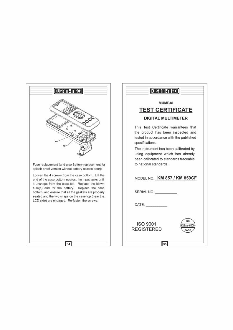
Loosen the 4 screws from the case bottom. Lift the
end of the case bottom nearest the input jacks until
it unsnaps from the case top. Replace the blown
fuse(s) and /or the battery. Replace the case
bottom, and ensure that all the gaskets are properly
seated and the two snaps on the case top (near the
LCD side) are engaged. Re-fasten the screws.
Fuse replacement (and also Battery replacement for
splash proof version without battery access door):
34
MUMBAI
TEST CERTIFICATE
DIGITAL MULTIMETER
This Test Certificate warrantees that
the product has been inspected and
tested in accordance with the published
specifications.
The instrument has been calibrated by
using equipment which has already
been calibrated to standards traceable
to national standards.
MODEL NO. _____________________KM 857 / KM 859CF
SERIAL NO. ___________
DATE: ___________
ISO 9001REGISTERED
QC
PASS
KUSAM-MECO
35
LIMITED WARRANTY
Each “KUSAM-MECO” product is warranted to be
free from defects in material and workmanship
under normal use & service. The warranty period is
one year (12 months) and begins from the date of
despatch of goods. In case any defect occurs in
functioning of the instrument, under proper use,
within the guarantee period, the same will be
rectified by us free of charges, provided the to and
fro freight charges are borne by you.
This warranty extends only to the original buyer or
end-user customer of a “KUSAM-MECO” authorized
dealer.
This warranty does not apply for damaged Ic’s,
fuses, disposable batteries, carrying case, test
leads, or to any product which in “KUSAM-MECO’s”
opinion, has been misused, altered, neglected,
contaminated or damaged by accident or abnormal
conditions of operation or handling.
“KUSAM-MECO” authorized dealer shall extend this
warranty on new and unused products to end-user
customers only but have no authority to extend a
greater or different warranty on behalf of “KUSAM-
MECO”.
“KUSAM-MECO’s” warranty obligation is limited, at
option, free of charge repair, or replacement of a
defective product which is returned to a “KUSAM-
MECO” authorized service center within the
warranty period.
36
G-17, Bharat Industrial Estate, T. J. Road,
Sewree(W), Mumbai - 400 015. INDIA.
Sales Direct : 022- 24156638
Tel.: 91-22-24124540, 24181649
Fax: 91-22-24149659
Email : [email protected];
Web : www.kusamelectrical.com
THIS WARRANTY IS BUYER’S SOLE AND
EXCLUSIVE REMEDY AND IS IN LIEU OF ALL
OTHER WARRANTIES, EXPRESS OR IMPLIED,
INCLUDING BUT NOT LIMITED TO ANY IMPLIED
WARRANTY OF MERCHANTABILITY OR
FITNESS FOR A PARTICULAR PURPOSE.
“KUSAM-MECO” SHALL NOT BE LIABLE FOR
ANY SPECIAL, INDIRECT, INCIDENTAL OR
CONSEQUENTIAL DAMAGES OR LOSSES,
INCLUDING LOSS OF DATA, ARISING FROM
ANY CAUSE WHATSOEVER.
All transaction are subject to Mumbai Jurisdiction.
37
®®
AN ISO 9001:2008 COMPANY