Digital M usic B ox - Harvey Mudd College
39
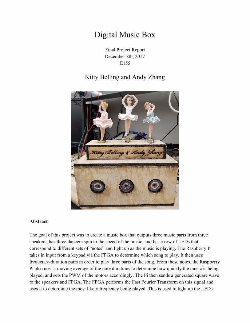
Digital Music Box Final Project Report December 8th, 2017 E155 Kitty Belling and Andy Zhang Abstract The goal of this project was to create a music box that outputs three music parts from three speakers, has three dancers spin to the speed of the music, and has a row of LEDs that correspond to different sets of “notes” and light up as the music is playing. The Raspberry Pi takes in input from a keypad via the FPGA to determine which song to play. It then uses frequency-duration pairs in order to play three parts of the song. From these notes, the Raspberry Pi also uses a moving average of the note durations to determine how quickly the music is being played, and sets the PWM of the motors accordingly. The Pi then sends a generated square wave to the speakers and FPGA. The FPGA performs the Fast Fourier Transform on this signal and uses it to determine the most likely frequency being played. This is used to light up the LEDs.
Transcript of Digital M usic B ox - Harvey Mudd College
Digital Music Box
Final Project Report December 8th, 2017
E155
Kitty Belling and Andy Zhang
Abstract The goal of this project was to create a music box that outputs three music parts from three speakers, has three dancers spin to the speed of the music, and has a row of LEDs that correspond to different sets of “notes” and light up as the music is playing. The Raspberry Pi takes in input from a keypad via the FPGA to determine which song to play. It then uses frequency-duration pairs in order to play three parts of the song. From these notes, the Raspberry Pi also uses a moving average of the note durations to determine how quickly the music is being played, and sets the PWM of the motors accordingly. The Pi then sends a generated square wave to the speakers and FPGA. The FPGA performs the Fast Fourier Transform on this signal and uses it to determine the most likely frequency being played. This is used to light up the LEDs.
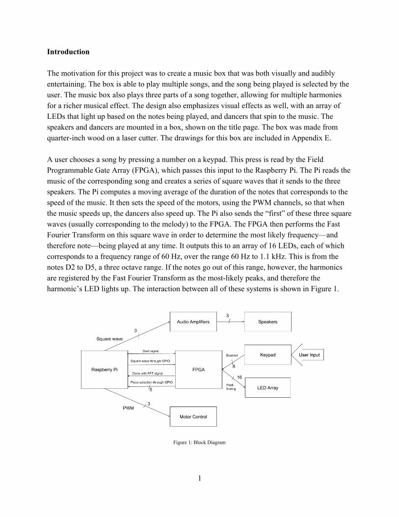
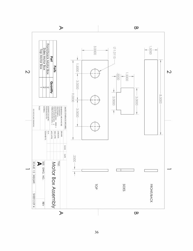
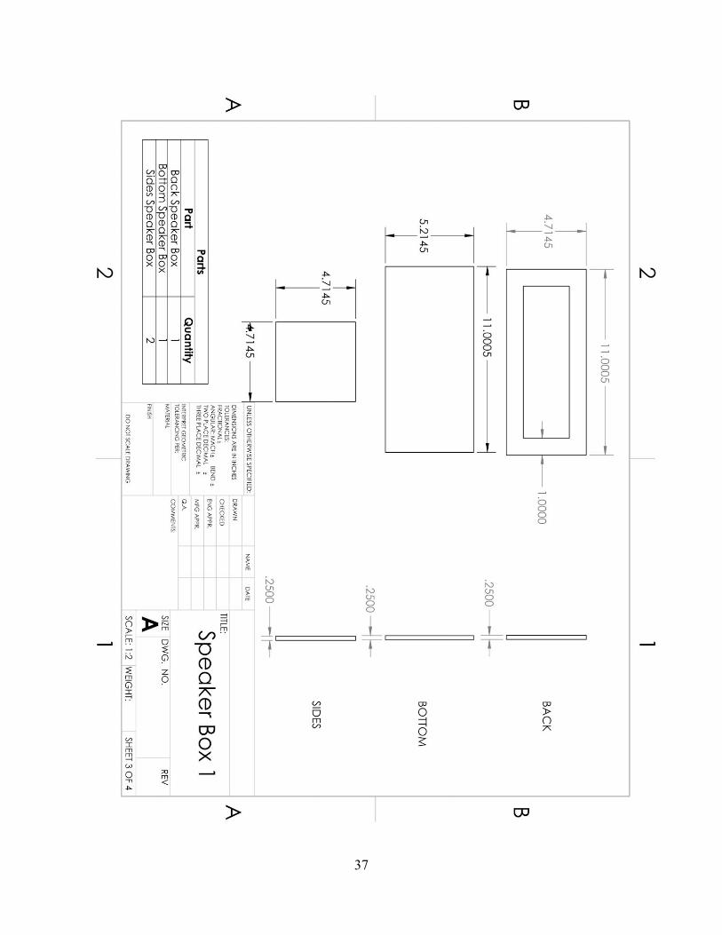
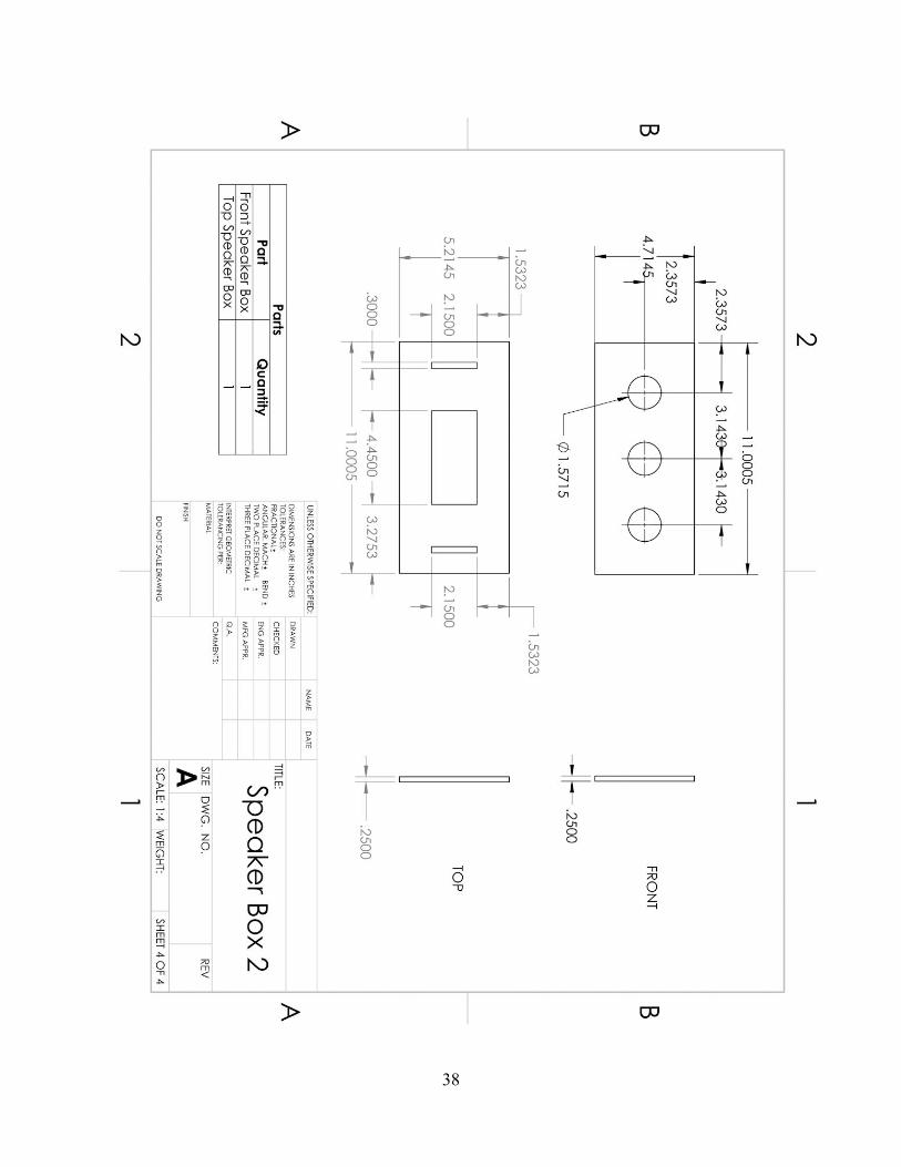
Introduction The motivation for this project was to create a music box that was both visually and audibly entertaining. The box is able to play multiple songs, and the song being played is selected by the user. The music box also plays three parts of a song together, allowing for multiple harmonies for a richer musical effect. The design also emphasizes visual effects as well, with an array of LEDs that light up based on the notes being played, and dancers that spin to the music. The speakers and dancers are mounted in a box, shown on the title page. The box was made from quarter-inch wood on a laser cutter. The drawings for this box are included in Appendix E. A user chooses a song by pressing a number on a keypad. This press is read by the Field Programmable Gate Array (FPGA), which passes this input to the Raspberry Pi. The Pi reads the music of the corresponding song and creates a series of square waves that it sends to the three speakers. The Pi computes a moving average of the duration of the notes that corresponds to the speed of the music. It then sets the speed of the motors, using the PWM channels, so that when the music speeds up, the dancers also speed up. The Pi also sends the “first” of these three square waves (usually corresponding to the melody) to the FPGA. The FPGA then performs the Fast Fourier Transform on this square wave in order to determine the most likely frequency—and therefore note—being played at any time. It outputs this to an array of 16 LEDs, each of which corresponds to a frequency range of 60 Hz, over the range 60 Hz to 1.1 kHz. This is from the notes D2 to D5, a three octave range. If the notes go out of this range, however, the harmonics are registered by the Fast Fourier Transform as the most-likely peaks, and therefore the harmonic’s LED lights up. The interaction between all of these systems is shown in Figure 1.
Figure 1: Block Diagram
1
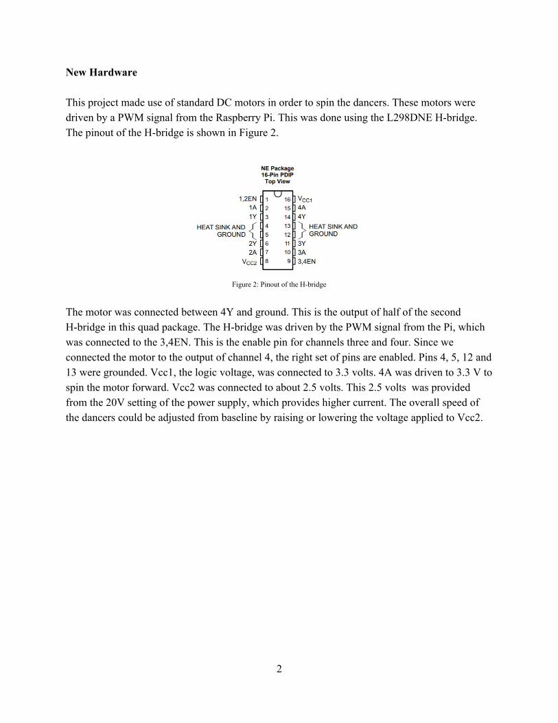
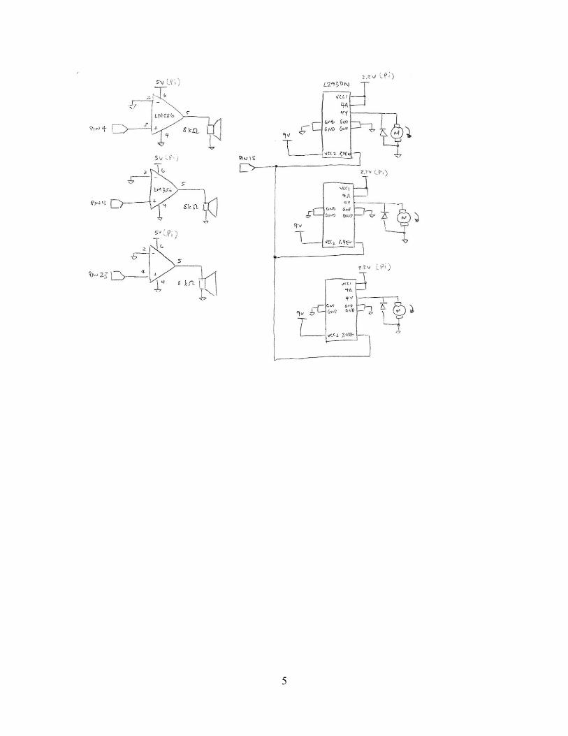
New Hardware This project made use of standard DC motors in order to spin the dancers. These motors were driven by a PWM signal from the Raspberry Pi. This was done using the L298DNE H-bridge. The pinout of the H-bridge is shown in Figure 2.
Figure 2: Pinout of the H-bridge
The motor was connected between 4Y and ground. This is the output of half of the second H-bridge in this quad package. The H-bridge was driven by the PWM signal from the Pi, which was connected to the 3,4EN. This is the enable pin for channels three and four. Since we connected the motor to the output of channel 4, the right set of pins are enabled. Pins 4, 5, 12 and 13 were grounded. Vcc1, the logic voltage, was connected to 3.3 volts. 4A was driven to 3.3 V to spin the motor forward. Vcc2 was connected to about 2.5 volts. This 2.5 volts was provided from the 20V setting of the power supply, which provides higher current. The overall speed of the dancers could be adjusted from baseline by raising or lowering the voltage applied to Vcc2.
2
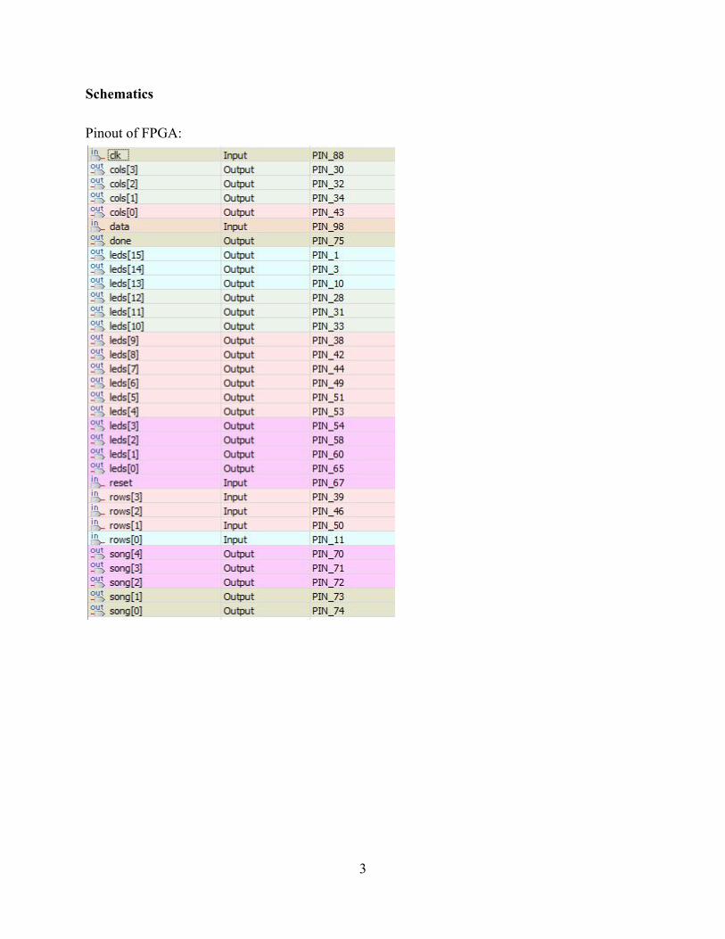
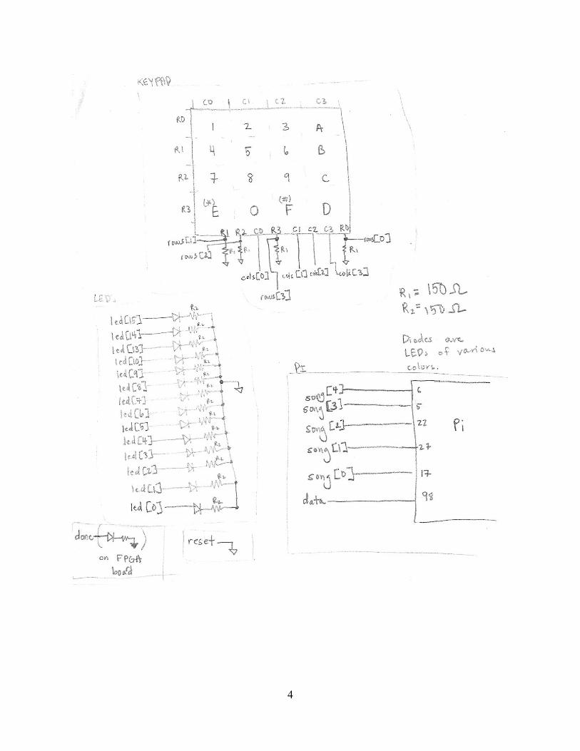
Schematics Pinout of FPGA:
3
4
5
Microcontroller Design The Raspberry Pi receives input on pins 5, 6, 17, 22, and 27, specifying which piece to play. It outputs three different square waves on pins 4, 13, and 23, as well as a PWM signal on pin 18. The Raspberry Pi is responsible for reading in a music score, comprised of notes and durations from a preset file. The Pi can parse an input of notes, written as {sC4, E}, where the first entry denotes C4#, and the second entry denotes a duration as long as an eighth note. This is achieved through type definitions and structs in the C code. These music files are provided as header files and on the Raspberry Pi. Further, the Raspberry Pi supports multiple audio channels for playback. It can read and play from three separate specifications of music data simultaneously, each corresponding to a different part of the same piece. While the pointers to the three music data arrays are held and updated separately, at the core the C program discretizes the music data into 25 millisecond chunks, so instead of separate notes and durations, the music is played as a series of 25 millisecond three-note chords. To generate the three separate frequencies, we use the pigpio library, which can be found at <http://abyz.me.uk/rpi/pigpio/> [2], in conjunction with the WiringPi library, which can be found at <http://wiringpi.com/> [3]. We used these libraries because the implementation for generating a frequency using the methods described in class required putting the C program to sleep while waiting for a delay timer, which means parallel execution is impossible. These libraries allow the generation of independent clock frequencies on the GPIO pins, as well as hardware PWM signals. However, we still use the EasyPIO library from class to add an extra channel of audio. The Raspberry Pi can read a provided music header file and select the correct array of notes to play based on the keypad input from the FPGA. We have bound “Concerto for Two Violins” by J. S. Bach to key 1, “Canon in D” by Johann Pachelbel to key 2, “Sleigh Ride” by Leroy Anderson to key 3, and “He’s a Pirate” by Klaus Badelt and Hans Zimmer to key 4. We have also created a test music file that plays a C major scale with varying speeds and bound that music to key 5. Finally, the Raspberry Pi records a moving average of the durations of the previous three notes to estimate the current tempo of the song being played. This average is transformed into a PWM duty cycle by a linear relation which maps 75, the fastest average, to a 100% duty cycle and 1200, the slowest average, to a 50% duty cycle. This is output on PWM channel 0 and sent to the enable pins on the three H-bridges.
6
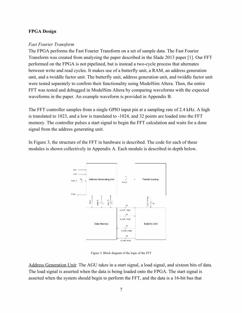
FPGA Design Fast Fourier Transform The FPGA performs the Fast Fourier Transform on a set of sample data. The Fast Fourier Transform was created from analyzing the paper described in the Slade 2013 paper [1]. Our FFT performed on the FPGA is not pipelined, but is instead a two-cycle process that alternates between write and read cycles. It makes use of a butterfly unit, a RAM, an address generation unit, and a twiddle factor unit. The butterfly unit, address generation unit, and twiddle factor unit were tested separately to confirm their functionality using ModelSim Altera. Then, the entire FFT was tested and debugged in ModelSim Altera by comparing waveforms with the expected waveforms in the paper. An example waveform is provided in Appendix B. The FFT controller samples from a single GPIO input pin at a sampling rate of 2.4 kHz. A high is translated to 1023, and a low is translated to -1024, and 32 points are loaded into the FFT memory. The controller pulses a start signal to begin the FFT calculation and waits for a done signal from the address generating unit. In Figure 3, the structure of the FFT in hardware is described. The code for each of these modules is shown collectively in Appendix A. Each module is described in depth below.
Figure 3: Block diagram of the logic of the FFT
Address Generation Unit: The AGU takes in a start signal, a load signal, and sixteen bits of data. The load signal is asserted when the data is being loaded onto the FPGA. The start signal is asserted when the system should begin to perform the FFT, and the data is a 16-bit bus that
7
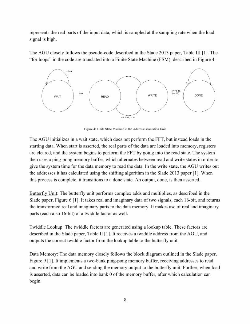
represents the real parts of the input data, which is sampled at the sampling rate when the load signal is high. The AGU closely follows the pseudo-code described in the Slade 2013 paper, Table III [1]. The “for loops” in the code are translated into a Finite State Machine (FSM), described in Figure 4.
Figure 4: Finite State Machine in the Address Generation Unit
The AGU initializes in a wait state, which does not perform the FFT, but instead loads in the starting data. When start is asserted, the real parts of the data are loaded into memory, registers are cleared, and the system begins to perform the FFT by going into the read state. The system then uses a ping-pong memory buffer, which alternates between read and write states in order to give the system time for the data memory to read the data. In the write state, the AGU writes out the addresses it has calculated using the shifting algorithm in the Slade 2013 paper [1]. When this process is complete, it transitions to a done state. An output, done, is then asserted. Butterfly Unit: The butterfly unit performs complex adds and multiplies, as described in the Slade paper, Figure 6 [1]. It takes real and imaginary data of two signals, each 16-bit, and returns the transformed real and imaginary parts to the data memory. It makes use of real and imaginary parts (each also 16-bit) of a twiddle factor as well. Twiddle Lookup: The twiddle factors are generated using a lookup table. These factors are described in the Slade paper, Table II [1]. It receives a twiddle address from the AGU, and outputs the correct twiddle factor from the lookup table to the butterfly unit. Data Memory: The data memory closely follows the block diagram outlined in the Slade paper, Figure 9 [1]. It implements a two-bank ping-pong memory buffer, receiving addresses to read and write from the AGU and sending the memory output to the butterfly unit. Further, when load is asserted, data can be loaded into bank 0 of the memory buffer, after which calculation can begin.
8
Keypad Scanner The FPGA also implements a keypad scanner to read from a 4x4 keypad. The system sampled the keypad to determine which button was pressed. This was done by cycling a high, 3.3V output through the columns using a Finite State Machine (FSM). The rows were then sampled to find out if there was a connection, and therefore a button pressed. Any connection between the two, recorded as a high row for a high column signal, would then be recorded and decoded to the corresponding decimal number pressed. Then, the keypad configured the output so that each decimal number used (1-5) would turn on a different output pin. Thus, there were five outputs from the keypad module to the Raspberry Pi. This was done on a slower clock of about 153 Hz in order to avoid switch bounce. Peak Finding On the last cycle of the FFT calculation, the FPGA simultaneously calculates the maximum energy frequency bin and clears the FFT memory blocks. It does this using a counter to count through the FFT output and uses a register to store the maximum value. The maximum energy frequency bin is outputted on 16 LEDs corresponding to the frequency range 60Hz to 1.1kHz with each LED corresponding to a 60 Hz bin. However, the LEDs don’t change on every note. This is because lower frequency are closer together, so there are about two notes per bin, but for higher frequencies, each note has its own LED. Thus, the LEDs change often enough over a wide range of frequencies, which is the desired effect.
9
Results Our music box functions as intended, and we have achieved all of the goals we set out for our project. Our box can read a user input from a keypad and select a song to play on the Pi. The specification is parsed correctly and output three separate music parts on three speakers. The dancers on the box also spin at a rate that is correlated with the music tempo, spinning faster as the music gets faster. Further, our implementation of 32-bit Fast Fourier Transform works effectively to determine the frequency of a square wave. Simulation results in Appendix B validate the correctness of our FFT. In hardware, the LEDs light up in time with the music and correctly indicate the note being played. One of the difficult aspects of the project was the Fast Fourier Transform module. Debugging required looking through a number of signals and waveforms to track down issues. Key parts of the FFT were the address generating unit and the data memory blocks. Thankfully, the paper by Slade was descriptive enough to implement everything correctly, with test cases and sample output. A subtle difference between our proposal and our final delivered project is the output of the FFT modules. The highest energy frequency bin is output on 16 LEDs, rather than the note being played. This is because at lower pitches, notes become closer together with smaller differences in frequency. To capture these smaller differences, a higher resolution FFT calculation would be required, likely a 1024-point FFT. To keep the project within our scope, we continued with our 32-point FFT calculation and elected to output the frequency bin instead of the note. At lower frequencies, two notes can occupy the same bin. However, at higher frequencies, it is usually one note per bin. As such, the desired effect of the LEDs changing with the music is still achieved.
10
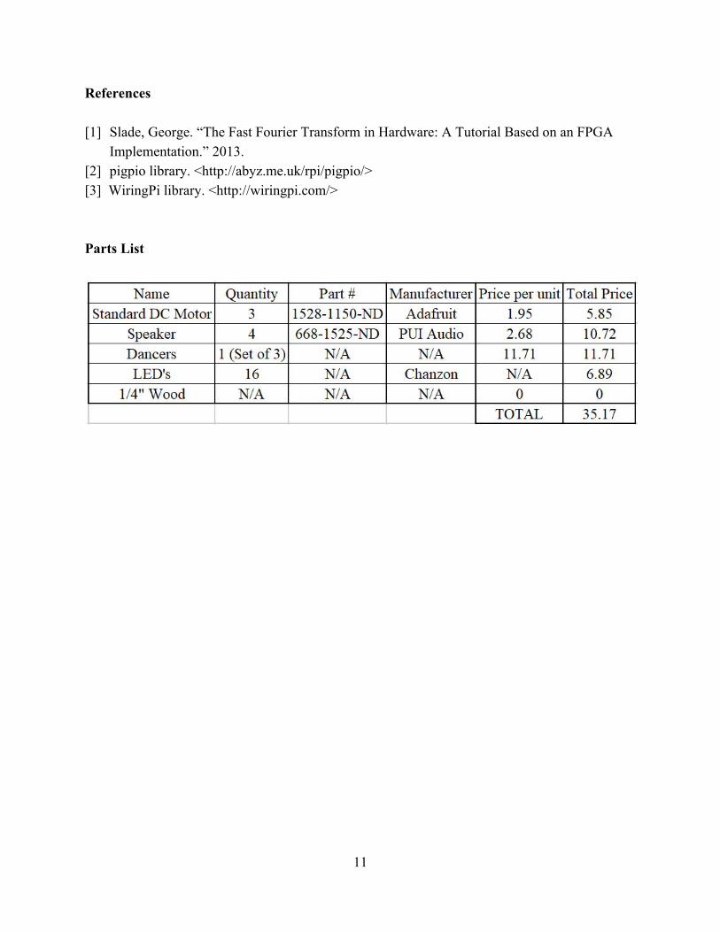
References [1] Slade, George. “The Fast Fourier Transform in Hardware: A Tutorial Based on an FPGA Implementation.” 2013. [2] pigpio library. <http://abyz.me.uk/rpi/pigpio/> [3] WiringPi library. <http://wiringpi.com/> Parts List
11
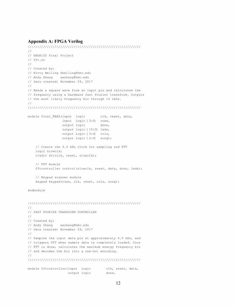
Appendix A: FPGA Verilog ///////////////////////////////////////////////////////////
//
// ENGR155 Final Project // fft.sv //
// Created by: // Kitty Belling [email protected] // Andy Zhang [email protected] // Date created: November 29, 2017 //
// Reads a square wave from an input pin and calculates the // frequency using a hardware fast Fourier transform. Outputs // the most likely frequency bin through 16 LEDs. //
///////////////////////////////////////////////////////////
module final_KBAZ(input logic clk, reset, data, input logic [3:0] rows, output logic done, output logic [15:0] leds, output logic [3:0] cols, output logic [2:0] song);
// Create the 4.9 kHz clock for sampling and FFT
logic slowclk;
clkdiv div(clk, reset, slowclk);
// FFT module fftcontroller control(slowclk, reset, data, done, leds);
// Keypad scanner module keypad keypad(rows, clk, reset, cols, song);
endmodule
///////////////////////////////////////////////////////////
//
// FAST FOURIER TRANSFORM CONTROLLER //
// Created by: // Andy Zhang [email protected] // Date created: November 29, 2017 //
// Samples the input data pin at approximately 4.9 kHz, and // triggers FFT when sample data is completely loaded. Once // FFT is done, calculates the maximum energy frequency bin // and decodes the bin into a one-hot encoding. //
///////////////////////////////////////////////////////////
module fftcontroller(input logic clk, reset, data, output logic done,
12
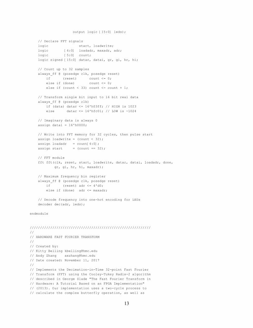
output logic [15:0] leds);
// Declare FFT signals logic start, loadwrite; logic [4:0] loadadr, maxadr, adr; logic [5:0] count; logic signed [15:0] datar, datai, gr, gi, hr, hi;
// Count up to 32 samples always_ff @ (posedge clk, posedge reset) if (reset) count <= 0; else if (done) count <= 0; else if (count < 33) count <= count + 1;
// Transform single bit input to 16 bit real data always_ff @ (posedge clk) if (data) datar <= 16'h03ff; // HIGH is 1023 else datar <= 16'hfc01; // LOW is -1024
// Imaginary data is always 0 assign datai = 16'h0000;
// Write into FFT memory for 32 cycles, then pulse start assign loadwrite = (count < 32); assign loadadr = count[4:0]; assign start = (count == 32);
// FFT module fft fft(clk, reset, start, loadwrite, datar, datai, loadadr, done, gr, gi, hr, hi, maxadr);
// Maximum frequency bin register always_ff @ (posedge clk, posedge reset) if (reset) adr <= 4'd0; else if (done) adr <= maxadr;
// Decode frequency into one-hot encoding for LEDs decoder dec(adr, leds);
endmodule
///////////////////////////////////////////////////////////
//
// HARDWARE FAST FOURIER TRANSFORM //
// Created by: // Kitty Belling [email protected] // Andy Zhang [email protected] // Date created: November 11, 2017 //
// Implements the Decimation-in-Time 32-point Fast Fourier // Transform (FFT) using the Cooley-Tukey Radix-2 algorithm // described in George Slade "The Fast Fourier Transform in // Hardware: A Tutorial Based on an FPGA Implementation" // (2013). Our implementation uses a two-cycle process to // calculate the complex butterfly operation, as well as
13
// to read and write to a ping-pong memory module. //
// Link to paper: // https://www.researchgate.net/publication/235995761_The_Fast_Fourier_ // Transform_in_Hardware_A_Tutorial_Based_on_an_FPGA_Implementation //
///////////////////////////////////////////////////////////
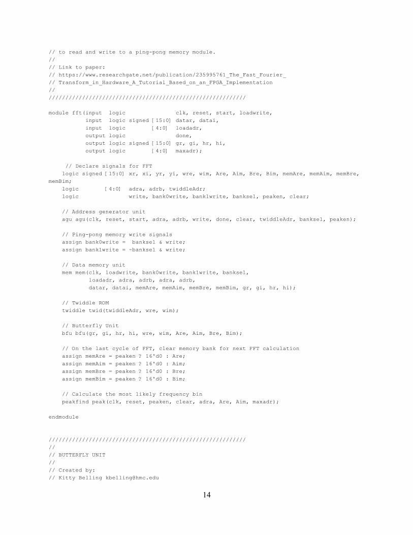
module fft(input logic clk, reset, start, loadwrite, input logic signed [15:0] datar, datai, input logic [4:0] loadadr, output logic done, output logic signed [15:0] gr, gi, hr, hi, output logic [4:0] maxadr);
// Declare signals for FFT logic signed [15:0] xr, xi, yr, yi, wre, wim, Are, Aim, Bre, Bim, memAre, memAim, memBre, memBim;
logic [4:0] adra, adrb, twiddleAdr; logic write, bank0write, bank1write, banksel, peaken, clear;
// Address generator unit agu agu(clk, reset, start, adra, adrb, write, done, clear, twiddleAdr, banksel, peaken);
// Ping-pong memory write signals assign bank0write = banksel & write; assign bank1write = ~banksel & write;
// Data memory unit mem mem(clk, loadwrite, bank0write, bank1write, banksel, loadadr, adra, adrb, adra, adrb, datar, datai, memAre, memAim, memBre, memBim, gr, gi, hr, hi);
// Twiddle ROM twiddle twid(twiddleAdr, wre, wim);
// Butterfly Unit bfu bfu(gr, gi, hr, hi, wre, wim, Are, Aim, Bre, Bim);
// On the last cycle of FFT, clear memory bank for next FFT calculation assign memAre = peaken ? 16'd0 : Are; assign memAim = peaken ? 16'd0 : Aim; assign memBre = peaken ? 16'd0 : Bre; assign memBim = peaken ? 16'd0 : Bim;
// Calculate the most likely frequency bin peakfind peak(clk, reset, peaken, clear, adra, Are, Aim, maxadr);
endmodule
///////////////////////////////////////////////////////////
//
// BUTTERFLY UNIT //
// Created by: // Kitty Belling [email protected]
14
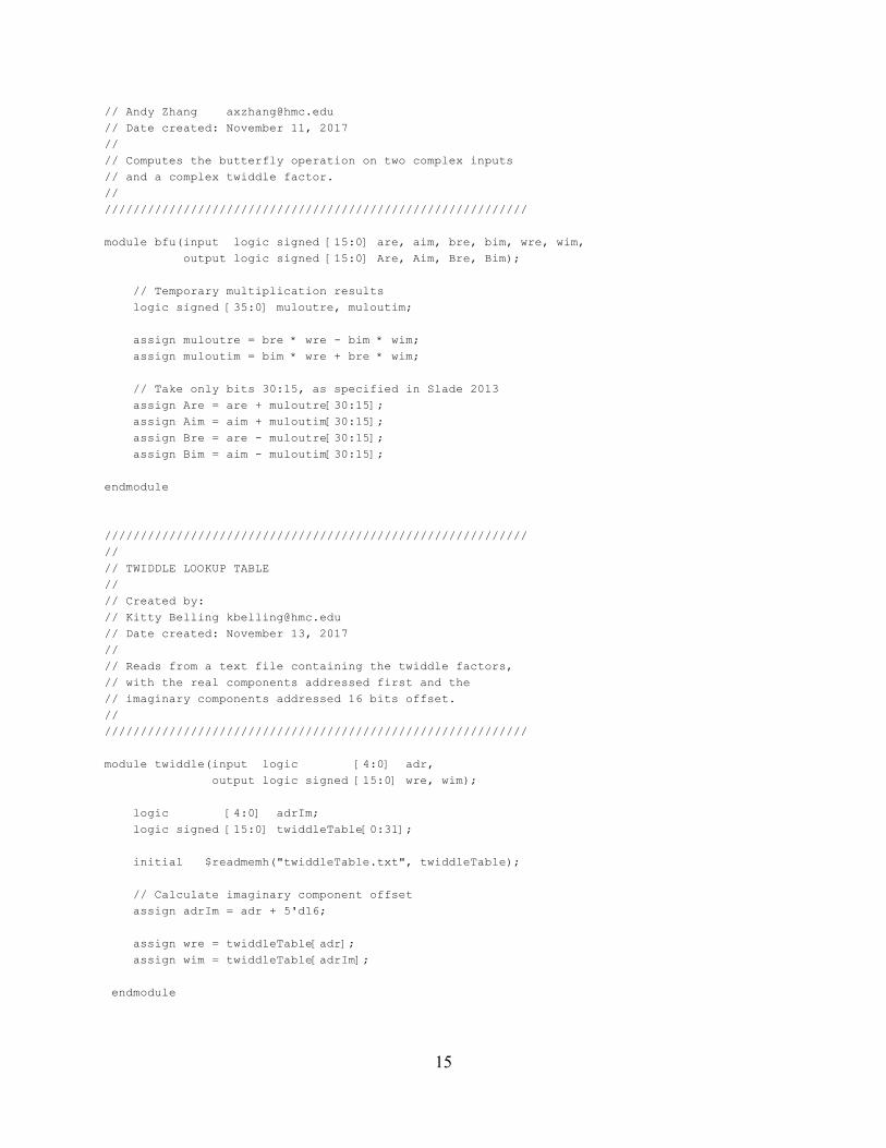
// Andy Zhang [email protected] // Date created: November 11, 2017 //
// Computes the butterfly operation on two complex inputs // and a complex twiddle factor. //
///////////////////////////////////////////////////////////
module bfu(input logic signed [15:0] are, aim, bre, bim, wre, wim, output logic signed [15:0] Are, Aim, Bre, Bim);
// Temporary multiplication results logic signed [35:0] muloutre, muloutim;
assign muloutre = bre * wre - bim * wim; assign muloutim = bim * wre + bre * wim;
// Take only bits 30:15, as specified in Slade 2013 assign Are = are + muloutre[30:15]; assign Aim = aim + muloutim[30:15]; assign Bre = are - muloutre[30:15]; assign Bim = aim - muloutim[30:15];
endmodule
///////////////////////////////////////////////////////////
//
// TWIDDLE LOOKUP TABLE //
// Created by: // Kitty Belling [email protected] // Date created: November 13, 2017 //
// Reads from a text file containing the twiddle factors, // with the real components addressed first and the // imaginary components addressed 16 bits offset. //
///////////////////////////////////////////////////////////
module twiddle(input logic [4:0] adr, output logic signed [15:0] wre, wim);
logic [4:0] adrIm; logic signed [15:0] twiddleTable[0:31];
initial $readmemh("twiddleTable.txt", twiddleTable);
// Calculate imaginary component offset assign adrIm = adr + 5'd16;
assign wre = twiddleTable[adr]; assign wim = twiddleTable[adrIm];
endmodule
15
///////////////////////////////////////////////////////////
//
// DATA MEMORY //
// Created by: // Kitty Belling [email protected] // Andy Zhang [email protected] // Date created: November 18, 2017 //
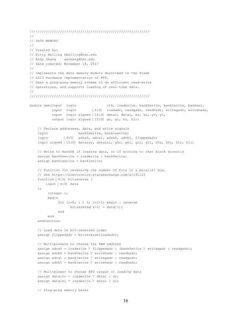
// Implements the data memory module described in the Slade // 2013 hardware implementation of FFT. // Uses a ping-pong memory scheme to do efficient read-write // operations, and supports loading of real-time data. //
///////////////////////////////////////////////////////////
module mem(input logic clk, loadwrite, bank0write, bank1write, banksel, input logic [4:0] loadadr, readgadr, readhadr, writegadr, writehadr, input logic signed [15:0] datar, datai, xr, xi, yr, yi, output logic signed [15:0] gr, gi, hr, hi);
// Declare addresses, data, and write signals logic bank0awrite, bank1awrite; logic [4:0] adra0, adra1, adrb0, adrb1, flippedadr; logic signed [15:0] datainr, dataini, g0r, g0i, g1r, g1i, h0r, h0i, h1r, h1i;
// Write to Bank0A if loading data, or if writing to that block directly assign bank0awrite = loadwrite | bank0write; assign bank1awrite = bank1write;
// Function for reversing the number of bits in a parallel bus. // See https://electronics.stackexchange.com/a/191125 function [4:0] bitreverse ( input [4:0] data ); integer i; begin for (i=0; i < 5; i=i+1) begin : reverse bitreverse[4-i] = data[i]; end end endfunction
// Load data in bit-reversed order assign flippedadr = bitreverse(loadadr);
// Multiplexers to choose the RAM address assign adra0 = loadwrite ? flippedadr : (bank0write ? writegadr : readgadr); assign adrb0 = bank0write ? writehadr : readhadr; assign adra1 = bank1write ? writegadr : readgadr; assign adrb1 = bank1write ? writehadr : readhadr;
// Multiplexer to choose BFU output or loading data assign datainr = loadwrite ? datar : xr; assign dataini = loadwrite ? datai : xi;
// Ping-pong memory banks
16
ram ram0r(clk, datainr, yr, adra0, adrb0, bank0awrite, bank0write, g0r, h0r); ram ram0i(clk, dataini, yi, adra0, adrb0, bank0awrite, bank0write, g0i, h0i); ram ram1r(clk, xr, yr, adra1, adrb1, bank1awrite, bank1write, g1r, h1r); ram ram1i(clk, xi, yi, adra1, adrb1, bank1awrite, bank1write, g1i, h1i);
// Output multiplexer based on current FFT level from bankselect signal assign gr = banksel ? g1r : g0r; assign gi = banksel ? g1i : g0i; assign hr = banksel ? h1r : h0r; assign hi = banksel ? h1i : h0i;
endmodule
///////////////////////////////////////////////////////////
//
// TWO-PORT RANDOM ACCESS MEMORY //
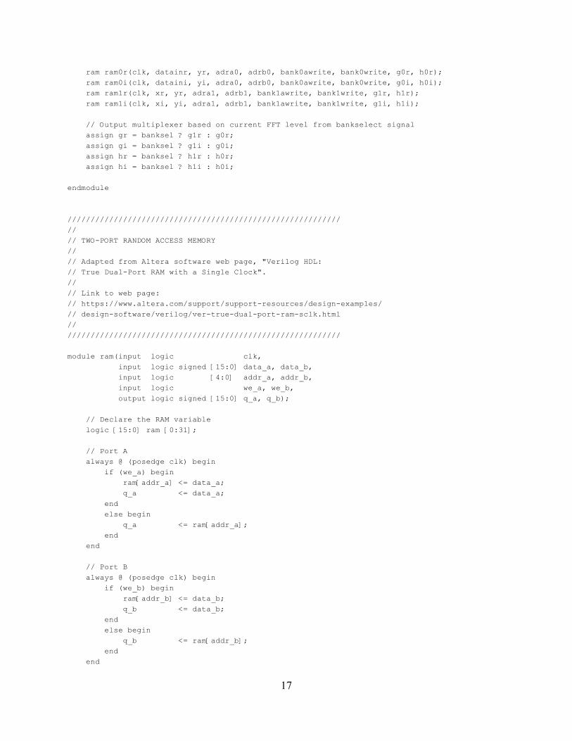
// Adapted from Altera software web page, "Verilog HDL: // True Dual-Port RAM with a Single Clock". //
// Link to web page: // https://www.altera.com/support/support-resources/design-examples/ // design-software/verilog/ver-true-dual-port-ram-sclk.html //
///////////////////////////////////////////////////////////
module ram(input logic clk, input logic signed [15:0] data_a, data_b, input logic [4:0] addr_a, addr_b, input logic we_a, we_b, output logic signed [15:0] q_a, q_b);
// Declare the RAM variable logic [15:0] ram [0:31];
// Port A always @ (posedge clk) begin if (we_a) begin ram[addr_a] <= data_a; q_a <= data_a; end else begin q_a <= ram[addr_a]; end end
// Port B always @ (posedge clk) begin if (we_b) begin ram[addr_b] <= data_b; q_b <= data_b; end else begin q_b <= ram[addr_b]; end end
17
endmodule
///////////////////////////////////////////////////////////
//
// ADDRESS GENERATING UNIT //
// Created by: // Kitty Belling [email protected] // Andy Zhang [email protected] // Date created: November 16, 2017 //
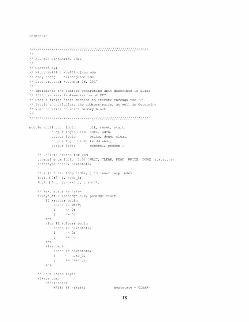
// Implements the address generating unit described in Slade // 2013 hardware implementation of FFT. // Uses a finite state machine to iterate through the FFT // levels and calculate the address pairs, as well as determine // when to write to which memory block. //
///////////////////////////////////////////////////////////
module agu(input logic clk, reset, start, output logic [4:0] adra, adrb,
output logic write, done, clear, output logic [4:0] twiddleAdr, output logic banksel, peaken);
// Declare states for FSM typedef enum logic [3:0] {WAIT, CLEAR, READ, WRITE, DONE} statetype; statetype state, nextstate;
// i is outer loop index, j is inner loop index logic [2:0] i, next_i; logic [4:0] j, next_j, j_shift;
// Next state register always_ff @ (posedge clk, posedge reset) if (reset) begin state <= WAIT; i <= 0; j <= 0; end else if (clear) begin state <= nextstate; i <= 0; j <= 0; end else begin state <= nextstate; i <= next_i; j <= next_j; end
// Next state logic always_comb case(state) WAIT: if (start) nextstate = CLEAR;
18
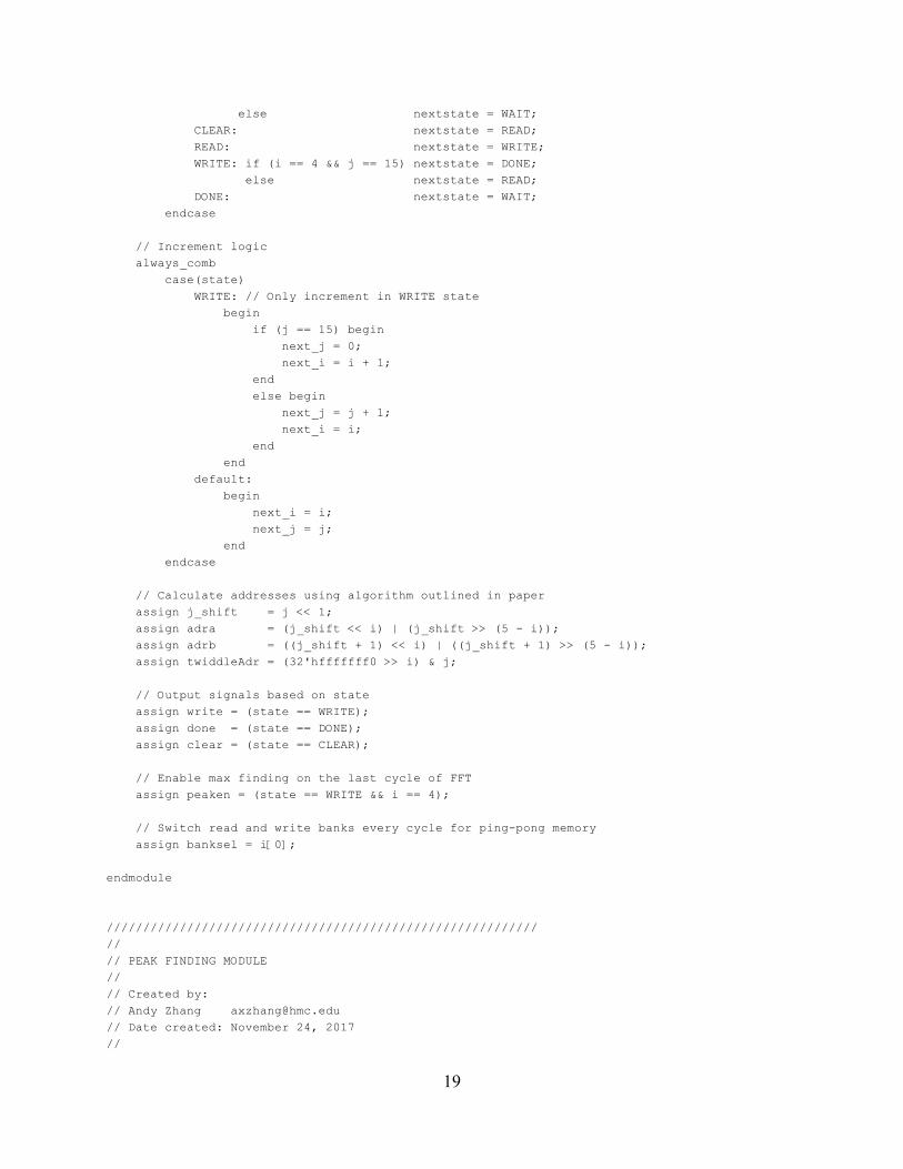
else nextstate = WAIT; CLEAR: nextstate = READ; READ: nextstate = WRITE; WRITE: if (i == 4 && j == 15) nextstate = DONE; else nextstate = READ; DONE: nextstate = WAIT; endcase
// Increment logic always_comb case(state) WRITE: // Only increment in WRITE state begin if (j == 15) begin next_j = 0; next_i = i + 1; end else begin next_j = j + 1; next_i = i; end end default: begin next_i = i; next_j = j; end endcase
// Calculate addresses using algorithm outlined in paper assign j_shift = j << 1; assign adra = (j_shift << i) | (j_shift >> (5 - i)); assign adrb = ((j_shift + 1) << i) | ((j_shift + 1) >> (5 - i)); assign twiddleAdr = (32'hfffffff0 >> i) & j;
// Output signals based on state assign write = (state == WRITE); assign done = (state == DONE); assign clear = (state == CLEAR);
// Enable max finding on the last cycle of FFT assign peaken = (state == WRITE && i == 4);
// Switch read and write banks every cycle for ping-pong memory assign banksel = i[0];
endmodule
///////////////////////////////////////////////////////////
//
// PEAK FINDING MODULE //
// Created by: // Andy Zhang [email protected] // Date created: November 24, 2017 //
19
// Iterates through the results of the last block of FFT and // calculates the bin with the highest energy. This bin is // the most likely frequency range. //
///////////////////////////////////////////////////////////
module peakfind(input logic clk, reset, enable, clear, input logic [4:0] adr, input logic signed [15:0] re, im, output logic [4:0] maxadr);
// Declare local maximum and intermediate result logic signed [31:0] maxresult, result;
// Update the maximum value always_ff @ (posedge clk, posedge reset, posedge clear) if (reset | clear) begin maxadr <= 4'd0; maxresult <= 32'd0; end else if (enable && ~clear && result > maxresult) begin maxadr <= adr; maxresult <= result; end
// Calculate the intermediate result assign result = re*re + im*im;
endmodule
///////////////////////////////////////////////////////////
//
// ADDRESS DECODER //
// Created by: // Andy Zhang [email protected] // Date created: November 27, 2017 //
// Transforms a 5-bit address from the FFT module into a // 16-bit one-hot encoding to send to LEDs on the board. //
///////////////////////////////////////////////////////////
module decoder(input logic [4:0] a, output logic [15:0] y);
// Only use addresses less than 16 assign y = (a < 16) ? (1 << a) : 16'd0;
endmodule
///////////////////////////////////////////////////////////
//
// CLOCK DIVIDER //
20
// Created by: // Andy Zhang [email protected] // Date created: November 27, 2017 //
// Uses the FPGA onboard clock of 40 MHz to create a slower // clock for a samplng rate of 4.9 kHz for FFT. //
///////////////////////////////////////////////////////////
module clkdiv(input logic clk, reset, output logic slowclk);
logic [13:0] q; always_ff @ (posedge clk, posedge reset) if (reset) q <= 0; else q <= q + 1;
assign slowclk = q[13];
endmodule
///////////////////////////////////////////////////////////
//
// KEYPAD MODULE //
// Created by: // Kitty Belling [email protected] // Date created: November 27, 2017 //
// Implements a scanner for a 4x4 keypad. //
///////////////////////////////////////////////////////////
module keypad(input logic [3:0] R, input logic clk, reset, output logic [3:0] C, output logic [2:0] song);
// Create a new clock that will run the rest of the code. // This slower clock allows for values to stabilize before // the clock edges. logic nclk; freqChange newClk(clk, reset, nclk);
// Find out which button is being pressed. logic [4:0] numbPressed; whichButtonPressed setNum(R, nclk, reset, C, numbPressed);
// Hold number in a register; only change the number if // a new key is pressed. logic [4:0] oldNum;
always_ff @ (posedge nclk, posedge reset) if (reset) begin oldNum <= numbPressed; end
21
else if (oldNum !== numbPressed) begin oldNum = numbPressed; end else begin oldNum <= oldNum; end
always_comb case(oldNum[3:0]) 4'b1110: song = 3'b000; //reset if * is played 4'b0001: song = 3'b001; //song 1 4'b0010: song = 3'b010; //song 2 4'b0011: song = 3'b100; //song 3 default: song = 3'b000; //nothing endcase
endmodule
///////////////////////////////////////////////////////////
//
// BUTTON DECODER //
// Created by: // Kitty Belling [email protected] // Date created: November 27, 2017 //
// Takes in the values of the rows, clock and reset and outputs // and outputs the last number that has been pressed by setting // the columns. //
///////////////////////////////////////////////////////////
module whichButtonPressed(input logic [3:0] R, input logic clk, reset, output logic [3:0] C, output logic [4:0] numberPressed);
logic [3:0] state, nextstate;
assign C = state;
logic [7:0] tracked, ntracked;
always_ff @ (posedge clk, posedge reset) if (reset) begin state <= 4'b0000; tracked <= 8'd0; end else begin state <= nextstate; tracked <= ntracked; end
always_comb case(state) 4'b0000: nextstate = 4'b0001;
22
4'b0001: nextstate = 4'b0010; 4'b0010: nextstate = 4'b0100; 4'b0100: nextstate = 4'b1000; 4'b1000: nextstate = 4'b0000; default: nextstate = 4'b0000; endcase
always_comb case(state) 4'b0001: if(|R) ntracked = {R, C}; else ntracked = tracked; 4'b0010: if(|R) ntracked = {R, C}; else ntracked = tracked; 4'b0100: if(|R) ntracked = {R, C}; else ntracked = tracked; 4'b1000: if(|R) ntracked = {R, C}; else ntracked = tracked; default: ntracked = tracked; endcase
always_comb case(ntracked) 8'b10000010: numberPressed = 5'd0; 8'b00010001: numberPressed = 5'd1; 8'b00010010: numberPressed = 5'd2; 8'b00010100: numberPressed = 5'd3; 8'b00100001: numberPressed = 5'd4; 8'b00100010: numberPressed = 5'd5; 8'b00100100: numberPressed = 5'd6; 8'b01000001: numberPressed = 5'd7; 8'b01000010: numberPressed = 5'd8; 8'b01000100: numberPressed = 5'd9; 8'b00011000: numberPressed = 5'd10; 8'b00101000: numberPressed = 5'd11; 8'b01001000: numberPressed = 5'd12; 8'b10001000: numberPressed = 5'd13; 8'b10000001: numberPressed = 5'd14; 8'b10000100: numberPressed = 5'd15; default: numberPressed = 5'd0; endcase
endmodule
///////////////////////////////////////////////////////////
//
// CLOCK DIVIDER //
// Created by: // Kitty Belling [email protected] // Date created: November 27, 2017 //
// Takes in the clock, which has a frequency of // about 40 MHz, and output a new clock that has // a frequency of about 153 Hz. //
///////////////////////////////////////////////////////////
23
module freqChange(input logic clk, reset, output logic newclk);
logic [18:0] q; always_ff @ (posedge clk, posedge reset) if (reset) q <= 0; else q <= q + 1;
assign newclk = q[18];
endmodule
24
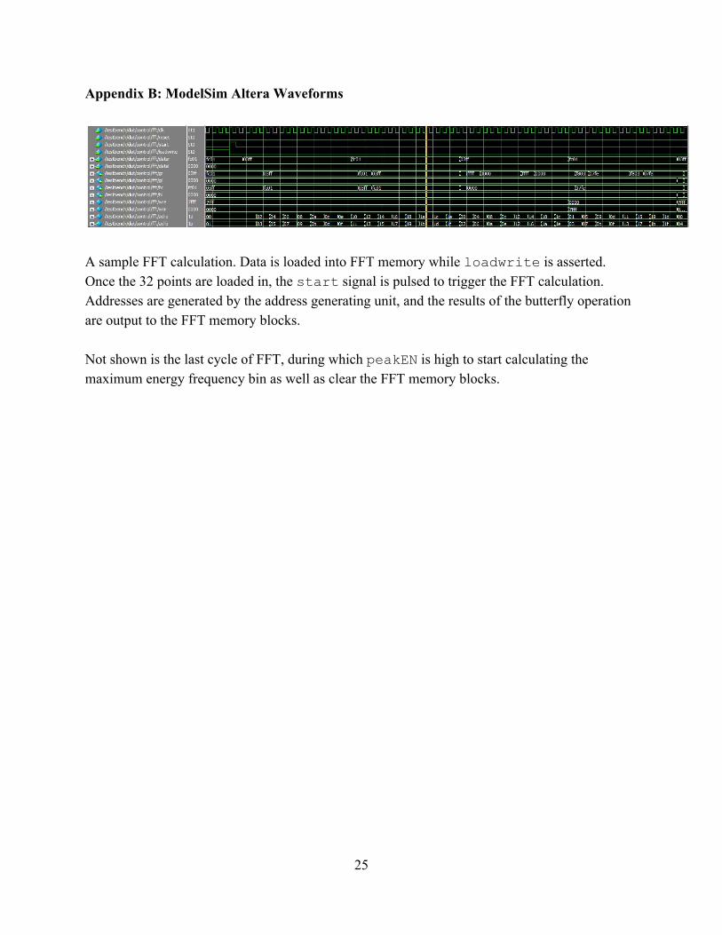
Appendix B: ModelSim Altera Waveforms
A sample FFT calculation. Data is loaded into FFT memory while loadwrite is asserted. Once the 32 points are loaded in, the start signal is pulsed to trigger the FFT calculation. Addresses are generated by the address generating unit, and the results of the butterfly operation are output to the FFT memory blocks. Not shown is the last cycle of FFT, during which peakEN is high to start calculating the maximum energy frequency bin as well as clear the FFT memory blocks.
25
Appendix C: Raspberry Pi C ///////////////////////////////////////////////////////////
//
// ENGR155 Final Project // playMusic.c //
// DIGITAL MUSIC SYNTHESIZER // Created by: // Kitty Belling [email protected] // Andy Zhang [email protected] //
// Uses the Raspberry Pi GPIO pins to generate square // waves at a given frequency. Reads in from a music // header file and plays three independent parts specified // by their note and duration. //
// Uses the pigpio library to generate independent hardware // clock and PWM signals on the pins. Compile using //
// gcc -g -pthread -o playMusic playMusic.c -lpigpio -lrt -lwiringPi -lpthread //
// Also uses the provided EasyPIO library, which can be found // at http://pages.hmc.edu/harris/class/e155/EasyPIO.h //
///////////////////////////////////////////////////////////
#include <sys/mman.h> #include <stdio.h> #include <stdlib.h> #include <fcntl.h> #include <unistd.h>
// Raspberry Pi libraries #include <pigpio.h> #include <wiringPi.h> #include <softPwm.h> #include "EasyPIO.h"
// Contains type definitions #include "note.h"
// Contains the music data to be played #include "bach.h" #include "canon.h" #include "sleigh.h" #include "pirate.h" #include "test.h"
// Plays a single note at a given frequency for // a given duration void playNote(int freq, int dur) { if (freq > 0) { // Calculate number of cycles and time // between peaks int cycles = (dur*freq)/1000; int delayTime = 500000 / freq; int i;
26
for (i = 0; i < cycles; i++) { // Write a HIGH myDigitalWrite(4, 1); delayMicros(delayTime); // Write a LOW myDigitalWrite(4, 0); delayMicros(delayTime); } } else { delayMicros(dur*1000); } }
// Plays a single chord for 25 ms // To get around issues with simultaneous clocks // and PWM frequencies, we chunk the frequencies // into 25 ms chunks and play every chord for // 25 ms. void playChord(int freq1, int freq2, int freq3) { gpioHardwarePWM(13, freq1, 500000); softToneWrite(23, freq2); playNote(freq3, 25); }
// Define a rest note, which is played when no song is selected Const note_t rest = {R, W};
int main(void) { // Initialize the Raspberry Pi for EasyPIO pioInit(); // Initialize pigpio if (gpioInitialise() < 0) printf("pigpio initialization error\n"); // Initialize wiringPi wiringPiSetupGpio();
// GPIO pin 4 is systimer tone generator myPinMode(4, OUTPUT);
// Software PWM from wiringPi if (softToneCreate(23) != 0) printf("wiringPi initialization error\n");
// Reading from keypad myPinMode(17, INPUT); myPinMode(27, INPUT); myPinMode(22, INPUT); myPinMode(5, INPUT); myPinMode(6, INPUT);
// Wait for input int in0 = 0; int in1 = 0; int in2 = 0; int in3 = 0; int in4 = 0; while (!in0 && !in1 && !in2 && !in3 && !in4) { in0 = myDigitalRead(17);
27
in1 = myDigitalRead(27); in2 = myDigitalRead(22); in3 = myDigitalRead(5); in4 = myDigitalRead(6); }
// Initialize our counters to the arrays int i0 = 0; int i1 = 0; int i2 = 0;
// Determine which piece to start with note_t* note0; note_t* note1; note_t* note2; if (in0) { note0 = &bach0[i0]; note1 = &bach1[i1]; note2 = &bach2[i2]; } else if (in1) { note0 = &canon0[i0]; note1 = &canon1[i1]; note2 = &canon2[i2]; } else if (in2) { note0 = &sleigh0[i0]; note1 = &sleigh1[i1]; note2 = &sleigh2[i2]; } else if (in3) { note0 = &pirate0[i0]; note1 = &pirate1[i1]; note2 = &pirate2[i2]; } else if (in4) { note0 = &test0[i0]; note1 = &test1[i1]; note2 = &test2[i2]; }
// Initialize running average int num0 = note0->d; int num1 = 0; int num2 = 0; double running_dur = 0.0; double pwm_duty = 0.0;
// Create note copies note_t copy0 = {note0->p, note0->d}; note_t copy1 = {note1->p, note1->d}; note_t copy2 = {note2->p, note2->d};
printf("Playing...\n");
// Continue playing forever while (1) {
28
int freq0 = copy0.p; int dur0 = copy0.d; int freq1 = copy1.p; int dur1 = copy1.d; int freq2 = copy2.p; int dur2 = copy2.d;
// Calculate new duration by subtracting 25 ms, // keeping at DONE if reached the end copy0.d = (dur0 != DONE) ? dur0 - 25 : DONE; copy1.d = (dur1 != DONE) ? dur1 - 25 : DONE; copy2.d = (dur2 != DONE) ? dur2 - 25 : DONE;
// Calculate running average of durations if (i0 == 0) { running_dur = (double) num0; } else if (i0 == 1) { running_dur = (double) (num0 + num1) / 2; } else { running_dur = (double) (num0 + num1 + num2) / 3; }
// Transform average to a PWM duty cycle pwm_duty = (-0.03111 * running_dur + 102.33) * 10000; gpioHardwarePWM(18, 120, pwm_duty);
printf("Note 0: %d, %d, %d\n", i0, freq0, dur0); printf("Note 1: %d, %d, %d\n", i1, freq1, dur1); printf("Note 2: %d, %d, %d\n", i2, freq2, dur2);
// Play a discrete chord playChord(freq0, freq1, freq2);
// Advance if duration is 25 and note is finished if (dur0 == 25) { I0++;
// Logic for handling running average if (i0 == 1) { if (in0) { num1 = bach0[i0].d; } else if (in1) { num1 = canon0[i0].d; } else if (in2) { num1 = sleigh0[i0].d; } else if (in3) {
num1 = pirate0[i0].d; } else if (in4) {
num1 = test0[i0].d; }
29
} else if (i0 == 2) { if (in0) { num2 = bach0[i0].d; } else if (in1) { num2 = canon0[i0].d; } else if (in2) { num2 = sleigh0[i0].d; }
else if (in3) { num2 = pirate0[i0].d;
} else if (in4) {
num2 = test0[i0].d; } } else { num0 = num1; num1 = num2; if (in0) { num2 = bach0[i0].d; } else if (in1) { num2 = canon0[i0].d; } else if (in2) { num2 = sleigh0[i0].d; }
else if (in3) { num2 = pirate0[i0].d;
} else if (in4) {
num2 = test0[i0].d; } }
// Logic to handle advancing to next note if (in0) { note0 = &bach0[i0]; } else if (in1) { note0 = &canon0[i0]; } else if (in2) { note0 = &sleigh0[i0]; }
else if (in3) { note0 = &pirate0[i0];
} else if (in4) {
note0 = &test0[i0]; } else { i0 = 0; note0 = &rest;
30
} copy0.p = note0->p; copy0.d = note0->d; }
// Advance to next note for second part if (dur1 == 25) { i1++; if (in0) { note1 = &bach1[i1]; } else if (in1) { note1 = &canon1[i1]; } else if (in2) { note1 = &sleigh1[i1]; }
else if (in3) { note1 = &pirate1[i1];
} else if (in4) {
note1 = &test1[i1]; } else { i1 = 0; note1 = &rest; } copy1.p = note1->p; copy1.d = note1->d; }
// Advance to next note for third part if (dur2 == 25) { i2++; if (in0) { note2 = &bach2[i2];
} else if (in1) { note2 = &canon2[i2]; } else if (in2) { note2 = &sleigh2[i2]; }
else if (in3) { note2 = &pirate2[i2];
} else if (in4) {
note2 = &test2[i2]; } else { i2 = 0; note2 = &rest; } copy2.p = note2->p; copy2.d = note2->d; }
31
// Read GPIO pins int newin0 = myDigitalRead(17); int newin1 = myDigitalRead(27); int newin2 = myDigitalRead(22); int newin3 = myDigitalRead(5); int newin4 = myDigitalRead(6);
// If input has changed if ((in0 != newin0) || (in1 != newin1) || (in2 != newin2) || (in3 != newin3) || (in4 != newin4)) { // Reset pointers to arrays i0 = 0; i1 = 0; i2 = 0;
// Choose new song to play if (newin0) { note0 = &bach0[i0]; note1 = &bach1[i1]; note2 = &bach2[i2]; } else if (newin1) { note0 = &canon0[i0]; note1 = &canon1[i1]; note2 = &canon2[i2]; } else if (newin2) { note0 = &sleigh0[i0]; note1 = &sleigh1[i1]; note2 = &sleigh2[i2]; } else if (newin3) {
note0 = &pirate0[i0]; note1 = &pirate1[i1]; note2 = &pirate2[i2];
} else if (newin4) {
note0 = &test0[i0]; note1 = &test1[i1]; note2 = &test2[i2];
} else { note0 = &rest; note1 = &rest; note2 = &rest; }
copy0.p = note0->p; copy0.d = note0->d; copy1.p = note1->p; copy1.d = note1->d; copy2.p = note2->p; copy2.d = note2->d;
// Reset running duration running_dur = 0; num0 = note0->d;
32
num1 = 0; num2 = 0; }
// Update input in0 = newin0; in1 = newin1; in2 = newin2; in3 = newin3; in4 = newin4; }
// Gracefully exit playChord(0, 0, 0);
printf("Done.\n"); return 0; }
33
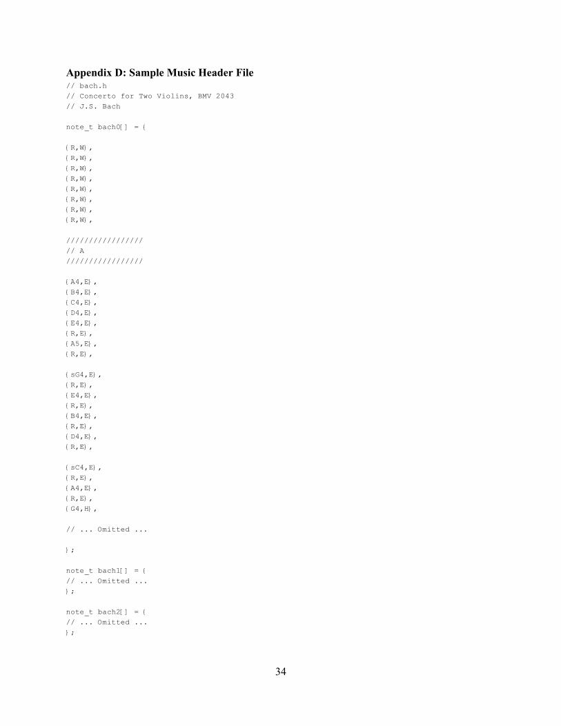
Appendix D: Sample Music Header File // bach.h // Concerto for Two Violins, BMV 2043 // J.S. Bach
note_t bach0[] = {
{R,W},
{R,W},
{R,W},
{R,W},
{R,W},
{R,W},
{R,W},
{R,W},
/////////////////
// A /////////////////
{A4,E},
{B4,E},
{C4,E},
{D4,E},
{E4,E},
{R,E},
{A5,E},
{R,E},
{sG4,E},
{R,E},
{E4,E},
{R,E},
{B4,E},
{R,E},
{D4,E},
{R,E},
{sC4,E},
{R,E},
{A4,E},
{R,E},
{G4,H},
// ... Omitted ...
};
note_t bach1[] = { // ... Omitted ... };
note_t bach2[] = { // ... Omitted ... };
34
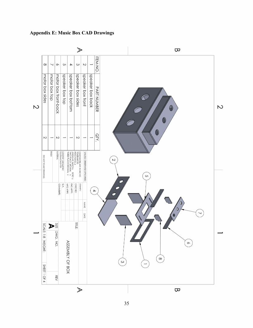
Appendix E: Music Box CAD Drawings
35
36
37
38