Digital - aqualisa.co.uk€¦ · HiQuDigitalBath installationinstructions Page5 Installation of...
14
HiQu Digital Bath installation instructions Page 1 HiQu Digital Bath Installation guide
Transcript of Digital - aqualisa.co.uk€¦ · HiQuDigitalBath installationinstructions Page5 Installation of...
HiQu Digital Bath installation instructions Page 1
HiQuDigitalBath
Installation guide

HiQu Digital Bath installation instructions Page 2
HiQu Digital Digital Bath
HiQu Digital Bath

Components (HP/Combi)
Literature not shown.
Literature not shown.
Components (Gravity Pumped)
HiQu Digital Bath installation instructions Page 3

HiQu Digital Bath installation instructions Page 4
Important informationSafety informationThis product must be installed by a competent person in accordance with all relevant current Water Supply Regulations.ALL PRODUCTS REQUIRING AN ELECTRICAL CONNECTI0N MUST BE INSTALLED BY A QUALIFIED PERSONFOLLOWING THE LATEST REVISION OF BS 7671 (WIRING REGULATIONS) AND CERTIFIED TO CURRENT BUILDINGREGULATIONS.This system should be installed so that other taps or appliances operated elsewhere within the premises do notsignificantly affect the flow.The Digital Bath must not be used with a hot water supply temperature of over 65ºC.The processor is supplied factory pre-set at maximum temperature of 45ºC. The maximum temperature is fullyadjustable to suit site conditions. If adjusted, we recommend the outlet temperature is set to a MAXIMUM of 46ºC.THE DIGITAL PROCESSOR MUST BE INSTALLED IN AN ACCESSIBLE LOCATION FOR SERVICING AND MAINTENANCE.The Digital processor must not be installed in situations where either the ambient temperature is likely to exceed 40ºCor where freezing may occur.The control must not be installed in situations where the ambient temperature is likely to fall below 5ºC or rise above40ºC.We do not recommend the use of HiQu Digital in steam therapy facilities.This appliance must be earthed.Cables which are chased into the wall must be protected by a suitably sized conduit or sheathing to allow forremoval in the event of service and maintenance purposes. Ensure that the conduit is run to avoid the controllerfixing holes.Surface mounted cables must also be protected by a suitable approved conduit, even in a loft, where there may bea risk of damage from vermin.The power lead must only be replaced by the manufacturer or his accredited agent.The user control is supplied from a safety low voltage source.This product is suitable for domestic use only.HiQu Digital is supplied complete with a 5 year guarantee.This product is not intended for use by persons (including children) with reduced physical, sensory or mentalcapabilities or lack of experience and knowledge, unless they have been given initial supervision or instructionconcerning the use of the product by a person responsible for their safety.Children should be supervised to ensure they do not play with the product.
Installation of Digital pumped processor (for gravity stored systems)The HiQu Digital pumped bath system is designed to operate up to maximum static pressure of 100kPa((1 bar)(10 metres head)(14.5psi)).Under no circumstances must the pumped processor be connected directly to the water main or in line withanother booster pump.The minimum actual capacity of the cold water storage cistern should be not less than 225 litres (50 gallons).The capacity of the hot water cylinder must be capable of meeting anticipated demand.

HiQu Digital Bath installation instructions Page 5
Installation of Digital standard processor (for balanced high pressure andunvented systems, combination boiler systems and separately pumpedgravity systems)Pressures: The HiQu Digital standard bath system is designed to operate up to a maximum static pressure of700kPa ((7 bar)(100psi)). Where pressures are likely to exceed 700kPa ((7 bar)(100psi)), a pressure reducing valvemust be fitted to the incoming mains supply. A setting of 400kPa ((4 bar)(60psi)) is recommended. It should benoted that daytime pressures approaching 600kPa ((6 bar)(80psi)) can rise above the stated maximum overnight.
Special notes for combination boiler systemsThe appliance must have a minimum domestic hot water rating of 24kW (80,000BTU) and be of the type fittedwith a fully modulating gas valve. If in any doubt, please contact the appliance manufacturer before installationcommences.PLEASENOTE:DUETOPERFORMANCECHARACTERISTICSOFCOMBINATIONBOILERS, SEASONAL INLETTEMPERATURECHANGEWILLAFFECTTHEPROCESSOROUTLETFLOWRATERESULTING INVARYINGBATHFLOWRATE. THISWILLAFFECTPRE-SETDEPTHLEVELS. INLETTEMPERATURECHANGEMAYALSOCAUSETHETEMPERATURE LED’STOFLASH; THIS ISNOTNECESSARILYCHANGINGTHEOUTLETTEMPERATURE.
Special notes for separately pumped gravity systemsWe recommend a twin ended pump with a MINIMUM pump rating of 1.5 bar. For optimum performance a twinended 2.5 bar pump should be used.The minimum actual capacity of the cold water storage cistern should be not less than 225 litres (50 gallons).The capacity of the hot water cylinder must be capable of meeting the anticipated demand.THIS PRODUCT IS NOT SUITABLE FOR USE WITH A SINGLE ENDED PUMP.
ConnectionsThis product incorporates ‘push fit’ type connections. Tube should be cut using a rotary type cutter and lubricatedusing a silicone-based lubricant or petroleum jelly (Vaseline or similar) prior to insertion into the fitting.
If plastic pipe is used, the tube insert must not increase the tube diameter or extend the cut-off length by more than2mm.TO MAXIMISE FLOW RATES WE RECOMMEND USING COPPER PIPE WITH THE MINIMUM AMOUNT OF ELBOWS. THESEFITTINGS ARE NOT SUITABLE FOR STAINLESS STEEL TUBE.
Pipe sizingLong pipe runs, on both inlet and outlet, will reduce the flow rate at the shower head. If long pipe runs areunavoidable, use copper pipe rather than plastic. If plastic pipe is used, minimise the number of elbows as the pipeinserts are very restrictive, consideration should be given to using 22mm plastic or copper pipe.
FlushingSome modern fluxes can be extremely corrosive and, if left in contact, will attack the working parts of this unit. Allsoldering must be completed and the pipe work thoroughly flushed out in accordance with current Water SupplyRegulations prior to connection of the product.
After installationFamiliarise the end user with the HiQu Digital bath operation and hand them this guide. Complete and post theguarantee card or register online at www.aqualisa.co.uk

HiQu Digital Bath installation instructions Page 6
Installation instructions
This product must be installed by a competent person in accordance
with the relevant current Water Supply Regulations.
70mm
In addition to the guide below it is essential that the written in-
structions overleaf are read and understood and that you have all
the necessary components (shown overleaf) before com-
mencing installation.
!
The HiQu Digital Bath system is supplied with universal fixings in-
tended to secure it to a suitable wall.!
90mm
445m
m
270m
m
350mm
265m
m
To ensure safe operation and installation of this product, the
processor MUST be installed in one of the orientations shown.1
!

HiQu Digital Bath installation instructions Page 7
Isolation valves are supplied with the Dig-
ital processor and must be fitted on both
inlets and the blended water outlet. All
pipe work should be run in 15mm pipe. All
pipe work should be supported. For exter-
nally pumped gravity fed installa-
tions, 22mm pipe work should be run
as close to the processor as possible before re-
ducing down to 15mm.
2
The inlet supply centres are 48mm. The inlet supply centres de-
viate from EN1111 and EN1287, but are deemed to be a
special case.
Please note arrow on isolation valve to indicate direction of flow.
Compression fittings should not be used on the inlet and outlet
spigots and may affect warranty if fitted.
!
Choose the position for your Digital processor as close to the bath
control as possible.
The processor may be sited in the roof space above the proposed
bath site, in the airing cupboard or behind a screwed bath panel if
more convenient. If siting in the roof space, ensure that freez-
ing cannot occur and that no insulation material is placed under
or over the processor. Please refer to the system layout dia-
grams.
3
! The distance between the Digital processor and bath control
must be within range of the 10m data cable supplied.
THE PROCESSOR MUST BE SITED IN A POSITION SO THAT AC-
CESS CAN BE GAINED FOR TESTING AND SERVICE PURPOSES.

HiQu Digital Bath installation instructions Page 8
Place the Digital processor on a solid
mounting surface, and place the fixing
feet into suitable positions. Mark then
drill and prepare suitable fixings before
securing the processor to the mounting
surface using the screws provided.
4
Flush through both hot and cold supply pipes.5The maximum hot water inlet temperature must be no more than
65˚C.!
Attach the supply pipes to the Digital
processor, ensuring that the cold and
hot feeds are fitted into the
appropriately marked inlets.
6
DO NOT SOLDER NEAR TO PLASTIC COMPONENTS.!
Run a pipe from the mixed water outlet on the Digital processor through
to the proposed siting for the bath fill outlet.7
Suitable non restrictive double check valves (not supplied) MUST
be fitted to the blended outlet pipe in line with current Water
Supply Regulations.
!

HiQu Digital Bath installation instructions Page 9
Drill and prepare the fixing points and 15mm data cable entry point
using the fixings provided, if suitable.10
11
Undo the fixing screw, remove the
controller assembly away from the
back plate and set aside.
8
Place the bath control back plate onto the finished wall surface in
the desired location and mark the fixing and data cable entry
points.
9
Connect the data cable to the rear of the controller.12
Apply a thin bead of mastic to the mas-
tic groove at the rear of the
back plate. Secure the back plate
to the wall using the screws provided,
if suitable.
Care should be taken to ensure the mounting holes do not pierce
the data cable conduit.!
HiQu Digital Bath installation instructions Page 10
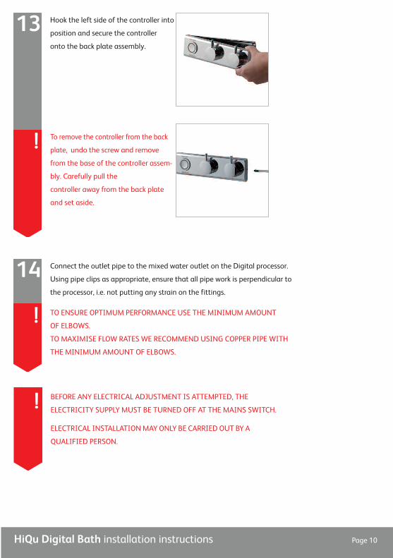
Hook the left side of the controller into
position and secure the controller
onto the back plate assembly.
13
To remove the controller from the back
plate, undo the screw and remove
from the base of the controller assem-
bly. Carefully pull the
controller away from the back plate
and set aside.
!
BEFORE ANY ELECTRICAL ADJUSTMENT IS ATTEMPTED, THE
ELECTRICITY SUPPLY MUST BE TURNED OFF AT THE MAINS SWITCH.
ELECTRICAL INSTALLATIONMAY ONLY BE CARRIED OUT BY A
QUALIFIED PERSON.
!
Connect the outlet pipe to the mixed water outlet on the Digital processor.
Using pipe clips as appropriate, ensure that all pipe work is perpendicular to
the processor, i.e. not putting any strain on the fittings.
14
TO ENSURE OPTIMUM PERFORMANCE USE THE MINIMUM AMOUNT
OF ELBOWS.
TO MAXIMISE FLOW RATES WE RECOMMEND USING COPPER PIPE WITH
THE MINIMUM AMOUNT OF ELBOWS.
!

HiQu Digital Bath installation instructions Page 11
Unscrew the single fixing on top of the
processor box and carefully tilt the lid up
and off the location lugs and pull the lid
clear.
16
Connect the processor power lead to a
double pole 3 amp fuse switched spur in-
corporated in the fixed wiring circuit, in
accordance with current wiring rules. En-
sure that this is located in an ac-
cessible, dry location and not in the
bathroom.
15
THIS APPLIANCE MUST BE EARTHED
We recommend protecting surface mounted cables in suitable ap-
proved conduit to avoid the risk of damage from vermin.
The data cable and power lead should also be clipped in place with ‘P’
clips or similar to avoid accidents.
!
Connect the low voltage data cable into
the socket adjacent to the temperature ad-
juster as indicated on the label. Feed
the cable out of the processor box en-
suring it is correctly routed within the data
cable channel.
17
A further data cable socket has been provided for use with a secondary
Digital remote start/stop controller. This can be accessed by carefully
snapping and removing the entry pillar and connecting the cable as de-
scribed above.
!
HiQu Digital Bath installation instructions Page 12
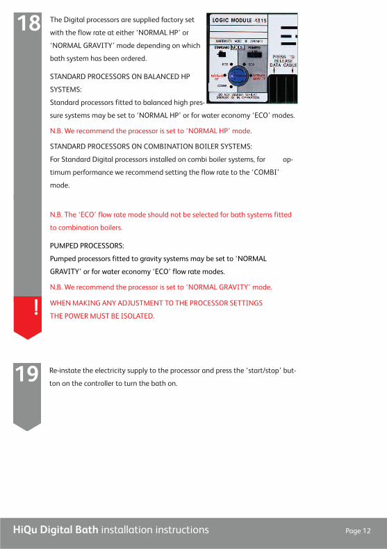
The Digital processors are supplied factory set
with the flow rate at either ‘NORMAL HP’ or
‘NORMAL GRAVITY’ mode depending on which
bath system has been ordered.
STANDARD PROCESSORS ON BALANCED HP
SYSTEMS:
Standard processors fitted to balanced high pres-
sure systems may be set to ‘NORMAL HP’ or for water economy ‘ECO’ modes.
N.B. We recommend the processor is set to ‘NORMAL HP’ mode.
STANDARD PROCESSORS ON COMBINATION BOILER SYSTEMS:
For Standard Digital processors installed on combi boiler systems, for op-
timum performance we recommend setting the flow rate to the ‘COMBI’
mode.
18
N.B. The ‘ECO’ flow rate mode should not be selected for bath systems fitted
to combination boilers.
PUMPED PROCESSORS:
Pumped processors fitted to gravity systems may be set to ‘NORMAL
GRAVITY’ or for water economy ‘ECO’ flow rate modes.
N.B. We recommend the processor is set to ‘NORMAL GRAVITY’ mode.
WHENMAKING ANY ADJUSTMENT TO THE PROCESSOR SETTINGS
THE POWERMUST BE ISOLATED.!
Re-instate the electricity supply to the processor and press the ‘start/stop’ but-
ton on the controller to turn the bath on.19
HiQu Digital Bath installation instructions Page 13
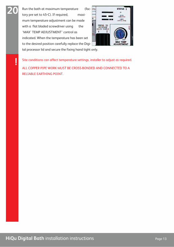
Run the bath at maximum temperature (fac-
tory pre set to 450C). If required, maxi-
mum temperature adjustment can be made
with a flat bladed screwdriver using the
‘MAX’ TEMP ADJUSTMENT’ control as
indicated. When the temperature has been set
to the desired position carefully replace the Digi-
tal processor lid and secure the fixing hand tight only.
20
Site conditions can affect temperature settings, installer to adjust as required.
ALL COPPER PIPE WORK MUST BE CROSS-BONDED AND CONNECTED TO A
RELIABLE EARTHING POINT.
!

Aqualisa Products Limited
The Flyer’s Way
Westerham Kent TN16 1DE
Customer helpline: 01959 560010
Brochure Hotline: 0800 652 3669
Website: www.aqualisa.co.uk
Email: [email protected]
Republic of Ireland
Sales enquiries: 01-864-3363
Service enquiries: 01-844-3212 Part No:700392 Issue 01 Jun 12
Please note that calls may be recorded for training and quality purposes
The company reserves the right to alter, change or modify the product specifications without prior warning
® Registered Trademark Aqualisa Products Limited
The Waste Electrical and Electronic Equipment (Producer Responsibility) Regulation 2004This product is outside the scope of the EuropeanWaste Electrical and Electronic Equipment Directive as interpreted within the UK.
In the UK this product can therefore be disposed of through commercial non-WEEEwaste facilities.
The original manufacturer does not accept any liability under theWEEE directive.