Digital Differential Current Protection Scheme of...
5
International Journal on Data Science and Technology 2019; 5(1): 35-39 http://www.sciencepublishinggroup.com/j/ijdst doi: 10.11648/j.ijdst.20190501.15 ISSN: 2472-2200 (Print); ISSN: 2472-2235 (Online) Digital Differential Current Protection Scheme of Transformer Using an Arduino UNO Microcontroller Emmanuel Ighodalo Okhueleigbe * , Joseph Ailenokhuoria Ogbekhiule Department of Electrical and Electronics Engineering, Federal University of Petroleum Resources (FUPRE), Effurun, Delta State, Nigeria Email address: * Corresponding author To cite this article: Emmanuel Ighodalo Okhueleigbe, Joseph Ailenokhuoria Ogbekhiule. Digital Differential Current Protection Scheme of Transformer Using an Arduino UNO Microcontroller. International Journal on Data Science and Technology. Vol. 5, No. 1, 2019, pp. 35-39. doi: 10.11648/j.ijdst.20190501.15 Received: February 28, 2019; Accepted: April 17, 2019; Published: June 3, 2019 Abstract: Transformers are the key equipment in electrical power transmission. So the use of transformers protection in electric power systems is very crucial and critical as they are required for efficient transportation of electricity to consumers for long term. This paper is concerned with the differential current protection scheme of transformer using a differential relay technique with arduino Uno microcontroller as a differential relay responsible for comparing the differential current values and sends trip signal to the relay (acting as circuit breaker) to open the circuit when there is fault in the protected zone as a result of imbalance in the differential current values. The system is efficient in transformer protection, gives better isolation, has accurate fault detection and quick response time to clearing faults Keywords: Transformers, Differential Current Protection, Arduino Uno Microcontroller, Relays, Current Transformers 1. Introduction The demand of electricity in our modern day as led to advancement in electrical power systems, which is reflected in the development of all the power system device generators, different sizes of transformers, transmission lines and the protection equipment. In A. C transmission, power transformer is one of the most important equipment. It is expensive uninterrupted and desired to be kept in good condition always to have supply. Due to advancement in technology and daily use of electrical devices by industries, organizations and individuals, there is an increase in electricity demand which most likely results systems overload, reducing its efficiency and can cause damage to the transformer [1]. Typically, Power systems are built to allow continuous generation, transmission and consumption of energy. The system is capable of sustaining a variety of environmental and operating impacts that resemble normal operating conditions which may include lightning striking the transmission lines, excessive loading, deterioration or breakdown of the equipment insulation resulting to power systems experiencing occasional faults such as phase to phase or phase to ground faults, over current, over voltage or even temperature based faults. These faults, as in the case of phase to phase or phase ground faults could cause an imbalance of phase current (i.e. differential current) and can be prevented using differential protection and microcontroller based relay protection. The Differential current protection scheme is based on the principle that the input power to the transformer under normal condition is equal to the output power and is concerned with having a differential or balanced current between the primary and secondary side which would be digitally displayed [2]. The protective relay techniques provide accurate reproduction of normal and abnormal conditions for correct sensing and operation. Different methods have being suggested by the researchers and are adopted in implementing a differential protection scheme for power transformer which is microcontroller based, [3] designed a differential current protection of single- phase transformer using Arduino with voice alert. The protection techniques employed differential relay mechanism with Arduino. At all times, the Arduino senses the condition of the transformer. If it finds any error then it sends
Transcript of Digital Differential Current Protection Scheme of...

International Journal on Data Science and Technology 2019; 5(1): 35-39
http://www.sciencepublishinggroup.com/j/ijdst
doi: 10.11648/j.ijdst.20190501.15
ISSN: 2472-2200 (Print); ISSN: 2472-2235 (Online)
Digital Differential Current Protection Scheme of Transformer Using an Arduino UNO Microcontroller
Emmanuel Ighodalo Okhueleigbe*, Joseph Ailenokhuoria Ogbekhiule
Department of Electrical and Electronics Engineering, Federal University of Petroleum Resources (FUPRE), Effurun, Delta State, Nigeria
Email address:
*Corresponding author
To cite this article: Emmanuel Ighodalo Okhueleigbe, Joseph Ailenokhuoria Ogbekhiule. Digital Differential Current Protection Scheme of Transformer Using
an Arduino UNO Microcontroller. International Journal on Data Science and Technology. Vol. 5, No. 1, 2019, pp. 35-39.
doi: 10.11648/j.ijdst.20190501.15
Received: February 28, 2019; Accepted: April 17, 2019; Published: June 3, 2019
Abstract: Transformers are the key equipment in electrical power transmission. So the use of transformers protection in
electric power systems is very crucial and critical as they are required for efficient transportation of electricity to consumers for
long term. This paper is concerned with the differential current protection scheme of transformer using a differential relay
technique with arduino Uno microcontroller as a differential relay responsible for comparing the differential current values and
sends trip signal to the relay (acting as circuit breaker) to open the circuit when there is fault in the protected zone as a result of
imbalance in the differential current values. The system is efficient in transformer protection, gives better isolation, has
accurate fault detection and quick response time to clearing faults
Keywords: Transformers, Differential Current Protection, Arduino Uno Microcontroller, Relays, Current Transformers
1. Introduction
The demand of electricity in our modern day as led to
advancement in electrical power systems, which is reflected
in the development of all the power system device
generators, different sizes of transformers, transmission lines
and the protection equipment. In A. C transmission, power
transformer is one of the most important equipment. It is
expensive uninterrupted and desired to be kept in good
condition always to have supply.
Due to advancement in technology and daily use of
electrical devices by industries, organizations and
individuals, there is an increase in electricity demand which
most likely results systems overload, reducing its efficiency
and can cause damage to the transformer [1].
Typically, Power systems are built to allow continuous
generation, transmission and consumption of energy. The
system is capable of sustaining a variety of environmental
and operating impacts that resemble normal operating
conditions which may include lightning striking the
transmission lines, excessive loading, deterioration or
breakdown of the equipment insulation resulting to power
systems experiencing occasional faults such as phase to
phase or phase to ground faults, over current, over voltage or
even temperature based faults. These faults, as in the case of
phase to phase or phase ground faults could cause an
imbalance of phase current (i.e. differential current) and can
be prevented using differential protection and microcontroller
based relay protection.
The Differential current protection scheme is based on the
principle that the input power to the transformer under
normal condition is equal to the output power and is
concerned with having a differential or balanced current
between the primary and secondary side which would be
digitally displayed [2]. The protective relay techniques
provide accurate reproduction of normal and abnormal
conditions for correct sensing and operation.
Different methods have being suggested by the researchers
and are adopted in implementing a differential protection
scheme for power transformer which is microcontroller
based, [3] designed a differential current protection of single-
phase transformer using Arduino with voice alert. The
protection techniques employed differential relay mechanism
with Arduino. At all times, the Arduino senses the condition
of the transformer. If it finds any error then it sends
36 Emmanuel Ighodalo Okhueleigbe and Joseph Ailenokhuoria Ogbekhiule: Digital Differential Current Protection
Scheme of Transformer Using an Arduino UNO Microcontroller
commands to the circuit breakers to trip the main potential
transformer and the buzzer gives an alert.
[4] Ochieng designed a microcontroller based power
transformer protection system which uses a current sensor
as the interfacing instrument between the current
transformer and the pic16f690 microcontroller. The
current sensor acs712x series was used in the project as
the interfacing instrument between the power transformer
and the pic16f690 microcontroller.
This paper is concern with the implementation of digital
differential current protection of a single phase transformer
using Arduino Uno microcontroller as a mechanism of
differential relay. A power transformer functions as a node to
connect two different voltage levels [3]. The fundamental
idea of the differential current protection scheme is to
provide protection to the transformer if any fault occurs in
the protected zone that will cause an imbalance in the
differential currents. The output power in a transformer is
equal to that of the input power hence, for differential current
protection of the current transformers reduces the currents at
the primary and secondary sides to a measureable value and
in such a way that they are equal [5]. When there is an
occurrence of internal fault an imbalanced or non-zero
differential current will flow through the operating coil of the
differential relay which would be substituted with a
microcontroller that sends a trip signal to the relays needed to
open the circuit. The differential protection scheme is
concerned with the faults that arise from associated
difficulties such as the magnetizing inrush current and
saturation. The magnetizing inrush current is a phenomenon
that occurs during brief initial state of energization of the
transformer even when the secondary side has no load
connected to it and has its current a lot higher than the rated
current [6-8]. It is transient in nature so it lasts for just a few
seconds and does not cause any permanent damage to the
transformer.
2. Components Used
Some of the major components needed are listed below:
Power transformer
Current transformer
Current sensors
Arduino Uno microcontroller
LCD 20x4
Voltage sensor
Variac
Loads: 60Wx2, 100W
Relays
Voltage regulator
Bridge rectifier
3. Work Principle
The power transformer to be protected is connected to the
main AC supply and delivered power (P=IV) to the output
terminal. The power transformer primary and secondary
currents are measured by the current transformers, which are
to be protected by the Arduino and the circuit breaker. The
step-down transformer is used to step down the primary or
source voltage from 220 to 12V. This 12V is regulated to 5V
(using L7805CV voltage regulator) which is the required
voltage for the Arduino. The current transformers are each
connected to the primary and secondary side of the step-up
transformer and are used to reduce the currents to a
measureable value that can be sensed by the current sensors.
The Arduino microcontroller acts as differential current
comparator connected to both current sensors ACS712 and
as control unit in this design. As a differential current
comparator it is used to compare the current values from
the outputs of both Current sensors at the primary and
secondary sides of the power respectively, computes their
resultant difference, which would process an instruction to
send a trip signal to the relay depending on its
programming and the time required to clear a fault. Acting
as a control unit, used for monitoring and controlling the
working activities of the protection zone and display
values of voltage and currents sensed by the voltage
sensor and current transformers respectively.
A bridge rectifier is used to convert the alternating current
from the secondary side of the step-down transformer to
direct current for use by the microcontroller. The current are
first connected in series and then in parallel to the secondary
side of the step-up transformer to display. Variac is
introduced in the system to vary and show the characteristics
of the differential protection scheme when differential
current is below zero and above zero respectively. The LCD
display is used to display the differential current values of the
transformer and to display the voltage and current level of the
system as well.
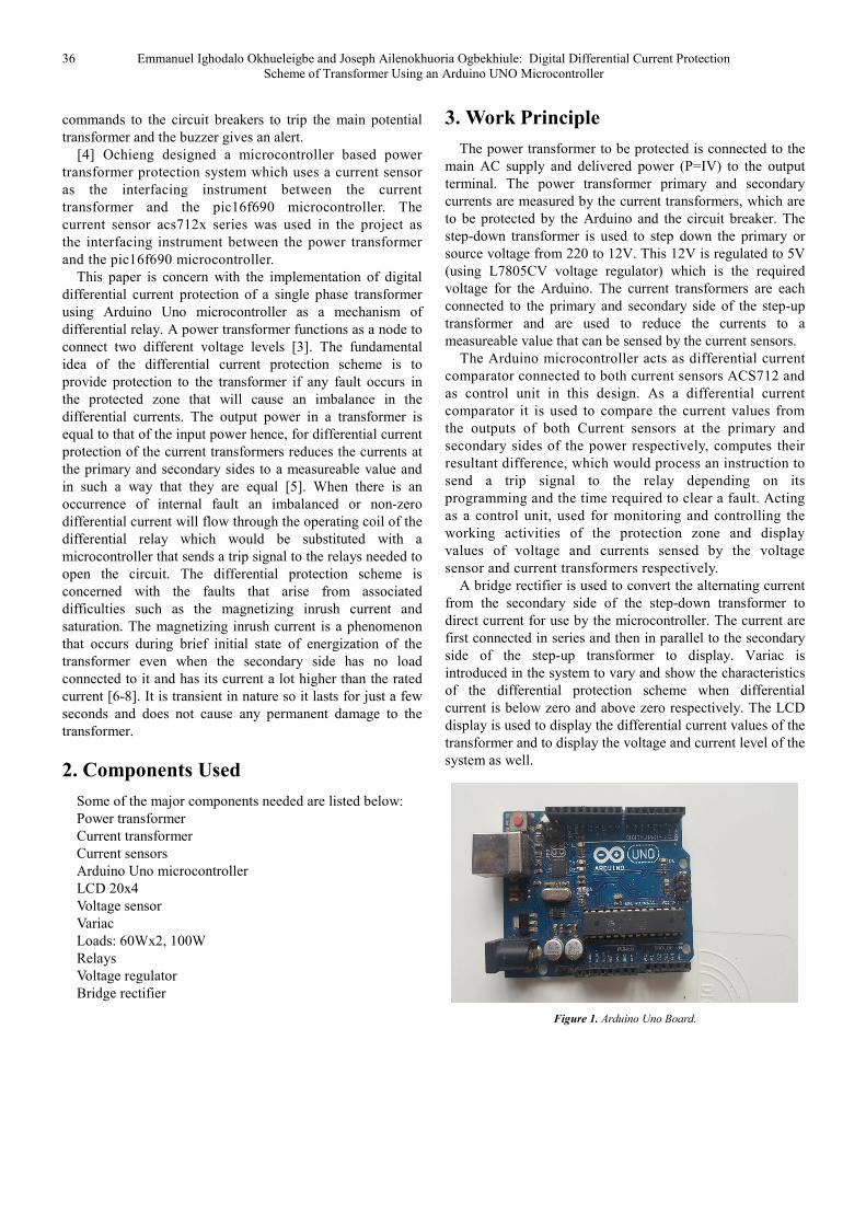
Figure 1. Arduino Uno Board.

International Journal on Data Science and Technology 2019; 5(1): 35-39 37
Figure 2. Proteus Simulation of the Protection Scheme.
38 Emmanuel Ighodalo Okhueleigbe and Joseph Ailenokhuoria Ogbekhiule: Digital Differential Current Protection
Scheme of Transformer Using an Arduino UNO Microcontroller
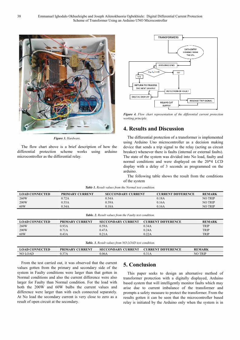
Figure 3. Hardware.
The flow chart above is a brief description of how the
differential protection scheme works using arduino
microcontroller as the differential relay.
Figure 4. Flow chart representation of the differential current protection
working principle.
4. Results and Discussion
The differential protection of a transformer is implemented
using Arduino Uno microcontroller as a decision making
device that sends a trip signal to the relay (acting as circuit
breaker) whenever there is faults (internal or external faults).
The state of the system was divided into No load, faulty and
normal conditions and were displayed on the 20*4 LCD
display with a delay of 3 seconds as programmed on the
arduino.
The following table shows the result from the conditions
of the system
Table 1. Result values from the Normal test condition.
LOAD CONNECTED PRIMARY CURRENT SECCONDARY CURRENT CURRENT DIFFERENCE REMARK
260W 0.72A 0.54A 0.18A NO TRIP
200W 0.55A 0.39A 0.16A NO TRIP
60W 0.34A 0.18A 0.16A NO TRIP
Table. 2. Result values from the Faulty test condition.
LOAD CONNECTED PRIMARY CURRENT SECCONDARY CURRENT CURRENT DIFFERENCE REMARK
260W 0.93A 0.59A 0.34A TRIP
200W 0.71A 0.47A 0.24A TRIP
60W 0.43A 0.21A 0.22A TRIP
Table. 3. Result values from NO LOAD test condition.
LOAD CONNECTED PRIMARY CURRENT SECCONDARY CURRENT CURRENT DIFFERENCE REMARK
NO LOAD 0.37A 0.06A 0.31A NO TRIP
From the test carried out, it was observed that the current
values gotten from the primary and secondary side of the
system in Faulty conditions were larger than that gotten in
Normal conditions and also the current difference were also
larger for Faulty than Normal condition. For the load with
both the 200W and 60W bulbs the current values and
difference were larger than with each connected separately.
At No load the secondary current is very close to zero as a
result of open circuit at the secondary.
5. Conclusion
This paper seeks to design an alternative method of
transformer protection with a digitally displayed, Arduino
based system that will intelligently monitor faults which may
arise due to current imbalance of the transformer and
prompts a safety measure to protect the transformer. From the
results gotten it can be seen that the microcontroller based
relay is initiated by the Arduino only when the system is in
International Journal on Data Science and Technology 2019; 5(1): 35-39 39
its faulty state. The microcontroller based relay is a
technological advancement or development as compared to
the use of conventional relays which improves the efficiency
and reliability of the system which could be beneficial to
both the society and its economic growth.
References
[1] K. Salunke, S. Sheikh, S. B Kunure (2016). “Transformer protection using microcontroller based relay and monitoring using GSM technology” International engineering research journal (IERJ), Vol. 2 issue 2, page 813-817, 2016, ISSN 2395 -1621.
[2] Adel, A. & Rahman, M. A. (2011). “A Software Design Technique for Differential Protection of Transformers”, International Electric Machines & Drives Conference (IEMDC), IEEE.
[3] Sarfaraz, N. S., Radica S. & Sandy M. N. R. (2015). “Digital Protection of Transformer using Arduino with Voice Alert”, International Journal of Innovations in Engineering and Technology (IJIET), Vol. 6, Issue 2.
[4] Ochieng’, A. O. (2015). “Microcontroller based power transformer protection”.
[5] S. M. Bashi, N. Marium and Rafa (2007). “Power Transformer Protection using Microcvontroller Based Relay.”, Journal of Applied Science 7 (12): 1602-1607, 2007. ISSN 1812-5654.
[6] Electric4u.com. (2018, August 27). https: //www.electrical4u.com/magnetizing-inrush-current-in-power-transformer/. Retrieved from www.electric4u.com: https: //www.electrical4u.com/magnetizing-inrush-current-in-power-transformer/.
[7] P. Afzal, P. Jigar, T. Raj, K. Abhishek, K Bariya. (2017). “Differential Current Protection of Transformer Using Arduino with Voice Alert” International Journal of Advance
Engineering and Research Development (IJARED), P-ISSN; 2348-6406.
[8] V. Kumar, k. Vivek, V. Verma, (2015) “A Microcontroller Based Online Fault Detection System” IJEE, VOL 7 page 1-4, 2015, ISSN 0973-7383.
[9] S. M. Bashi (2007). “Power Transformer Protection using Microcvontroller Based Relay.”, Journal of Applied Science 7 (12): 1602-1607, 2007. ISSN 1812-5654.
[10] V. Kumar (2015) “A Microcontroller Based Online Fault Detection System” IJEE, VOL 7 page 1-4, 2015, ISSN 0973-7383.
[11] Adel, A. (2011). “A Software Design Technique for Differential Protection of Transformers”, International Electric Machines & Drives Conference (IEMDC), IEEE.
[12] P. Afzal, P. Jigar, T. Raj, K. Abhishek, K Bariya. (2017). “Differential Current Protection of Transformer Using Arduino with Voice Alert” International Journal of Advance Engineering and Research Development (IJARED), P-ISSN; 2348-6406.
[13] Sarfaraz, N. S., (2015). “Digital Protection of Transformer using Arduino with Voice Alert”, International Journal of Innovations in Engineering and Technology (IJIET), Vol. 6, Issue 2.
[14] Electric4u.com. (2018, August 29). https://www.electrical4u.com/magnetizing-inrush-current-in-power-transformer/. Retrieved from www.electric4u.com: https: //www.electrical4u.com/magnetizing-inrush-current-in-power-transformer/.
[15] K.Salunke, (2016).”Transformer protection using microcontroller based relay and monitoring using GSM technology” International engineering research journal (IERJ), Vol. 2 issue 2, page 813-817, 2016, ISSN 2395 -1621.