Digital Design: Sequential Circuits for Registers and Counters Part - IV
35
Chapter 8 Sequential Circuits for Registers and Counters
-
Upload
atush-jain -
Category
Education
-
view
76 -
download
0
Transcript of Digital Design: Sequential Circuits for Registers and Counters Part - IV
Chapter 8
Sequential Circuits for Registers and Counters
Ch16L4- "Digital Principles and Design", Raj Kamal, Pearson Education, 2006 2
Lesson 4
RING AND JOHNSON RING AND JOHNSON COUNTERS COUNTERS
Ch16L4- "Digital Principles and Design", Raj Kamal, Pearson Education, 2006 3
• Ring Counter•• Johnson Counter Johnson Counter •• Odd Sequencer Switch tail Odd Sequencer Switch tail
(Twisted Ring) Johnson counter(Twisted Ring) Johnson counter•• Even Sequencer Switch tail Even Sequencer Switch tail
(Twisted Ring) Johnson counter(Twisted Ring) Johnson counter
Outline
Ch16L4- "Digital Principles and Design", Raj Kamal, Pearson Education, 2006 4
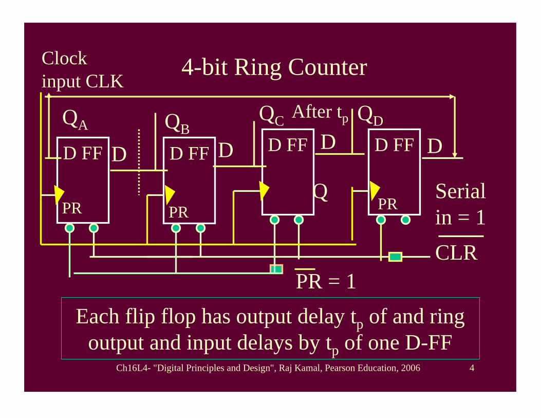
4-bit Ring Counter
D FFD FFD D FFD FF
Each flip flop has output delay tp of and ring output and input delays by tp of one D-FF
QA
Q
CLR
Clock input CLK
After tp
D D DQB
QDQC
PR PR PR
PR = 1
Serial in = 1
Ch16L4- "Digital Principles and Design", Raj Kamal, Pearson Education, 2006 5
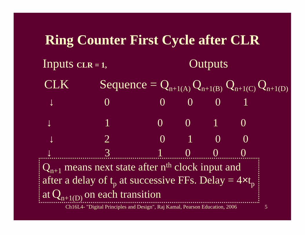
Ring Counter First Cycle after CLR
Inputs CLR = 1, Outputs
CLK Sequence = Qn+1(A) Qn+1(B) Qn+1(C) Qn+1(D)
Qn+1 means next state after nth clock input and after a delay of tp at successive FFs. Delay = 4×tp at Qn+1(D) on each transition
↓ 0 0 0 0 1
↓ 1 0 0 1 0↓ 2 0 1 0 0↓ 3 1 0 0 0
Ch16L4- "Digital Principles and Design", Raj Kamal, Pearson Education, 2006 6
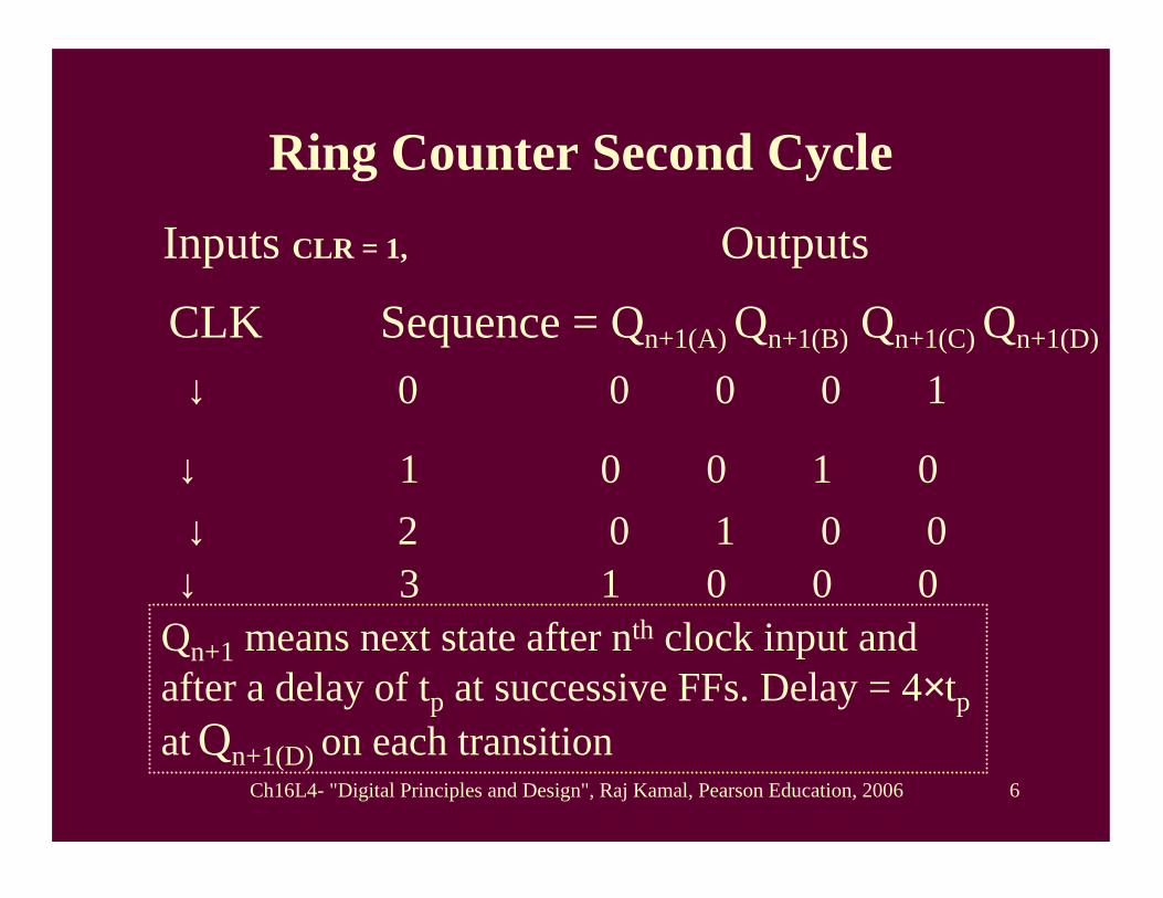
Ring Counter Second Cycle
Inputs CLR = 1, Outputs
CLK Sequence = Qn+1(A) Qn+1(B) Qn+1(C) Qn+1(D)
Qn+1 means next state after nth clock input and after a delay of tp at successive FFs. Delay = 4×tp at Qn+1(D) on each transition
↓ 0 0 0 0 1
↓ 1 0 0 1 0↓ 2 0 1 0 0↓ 3 1 0 0 0
Ch16L4- "Digital Principles and Design", Raj Kamal, Pearson Education, 2006 7
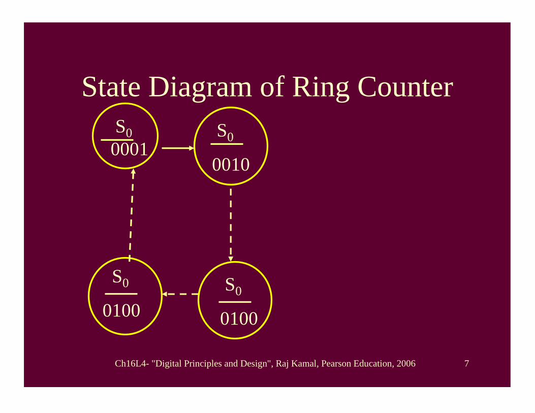
State Diagram of Ring CounterS00001
S0
0010
S0
0100
S0
0100
Ch16L4- "Digital Principles and Design", Raj Kamal, Pearson Education, 2006 8
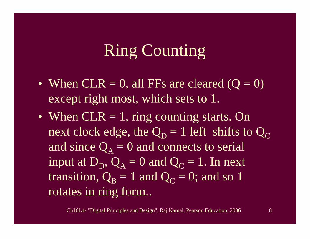
Ring Counting
• When CLR = 0, all FFs are cleared (Q = 0) except right most, which sets to 1.
• When CLR = 1, ring counting starts. On next clock edge, the QD = 1 left shifts to QCand since QA = 0 and connects to serial input at DD, QA = 0 and QC = 1. In next transition, QB = 1 and QC = 0; and so 1 rotates in ring form..
Ch16L4- "Digital Principles and Design", Raj Kamal, Pearson Education, 2006 9
Ring Counter Sequences
• Ring counter has 4 sequences: 0001, 0010, 0100, 1000, 0000

Ch16L4- "Digital Principles and Design", Raj Kamal, Pearson Education, 2006 10
• Ring Counters•• Johnson Counter Johnson Counter •• Odd Sequencer Switch tail Odd Sequencer Switch tail
(Twisted Ring) Johnson counter(Twisted Ring) Johnson counter•• Even Sequencer Switch tail Even Sequencer Switch tail
(Twisted Ring) Johnson counter(Twisted Ring) Johnson counter
Outline

Ch16L4- "Digital Principles and Design", Raj Kamal, Pearson Education, 2006 11
4-bit Johnson Counter
D FFD FFD D FFD FF
Each flip flop has output delay tp of and ring output and input delays by tp of one D-FF
QA
Q
CLR
Clock input CLK
After tp
D D DQB
QDQC
PR PR PR
PR = 1
Serial in = 1
Ch16L4- "Digital Principles and Design", Raj Kamal, Pearson Education, 2006 12
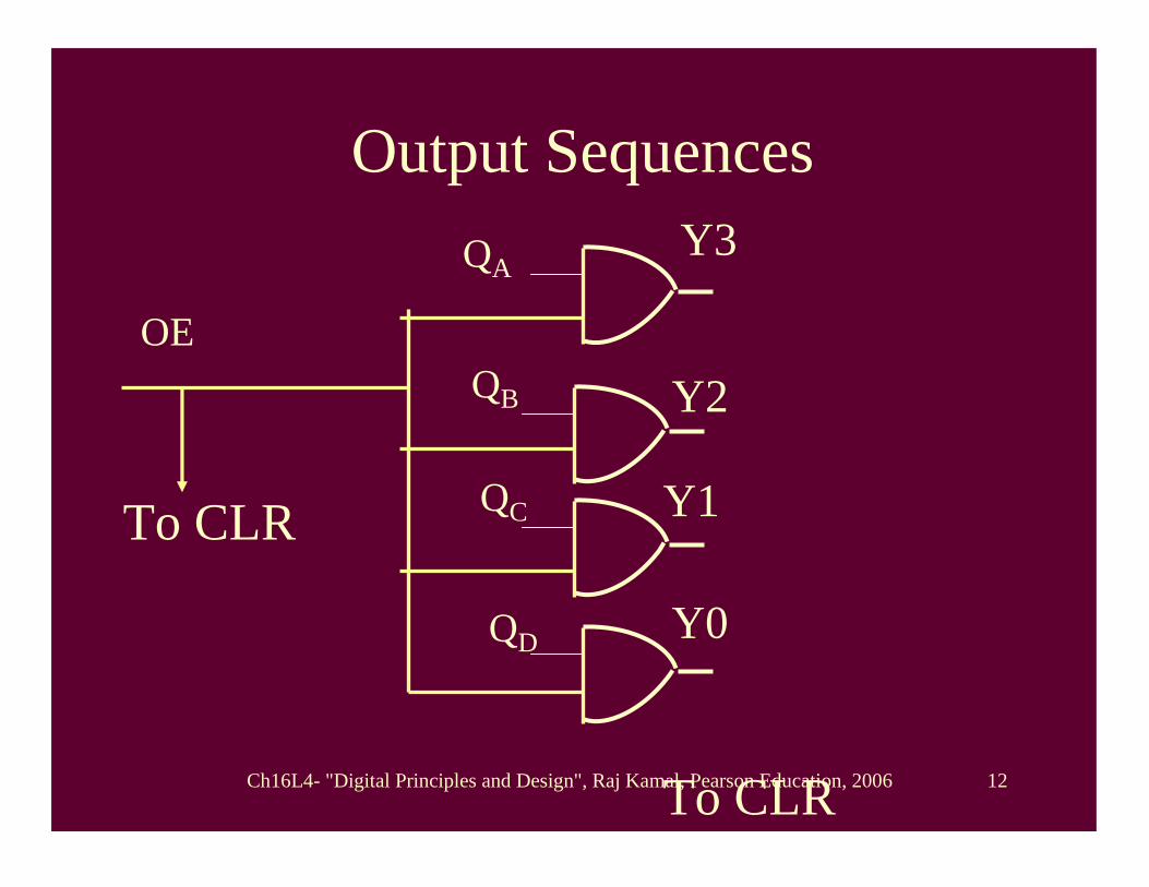
Output Sequences
OE
To CLR
QAY3
To CLR
QB
QC
QD
Y2
Y1
Y0
Ch16L4- "Digital Principles and Design", Raj Kamal, Pearson Education, 2006 13
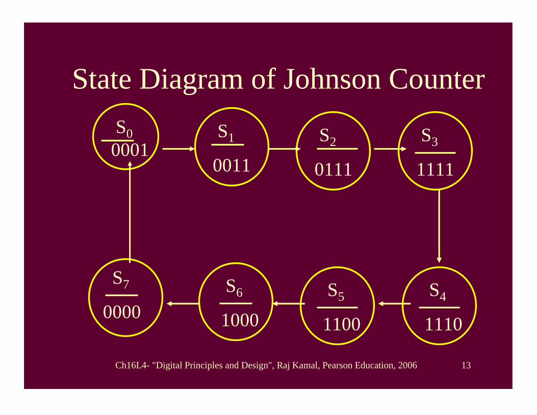
State Diagram of Johnson CounterS00001
S1
0011
S6
1000
S7
0000
S2
0111
S5
1100
S3
1111
S4
1110
Ch16L4- "Digital Principles and Design", Raj Kamal, Pearson Education, 2006 14
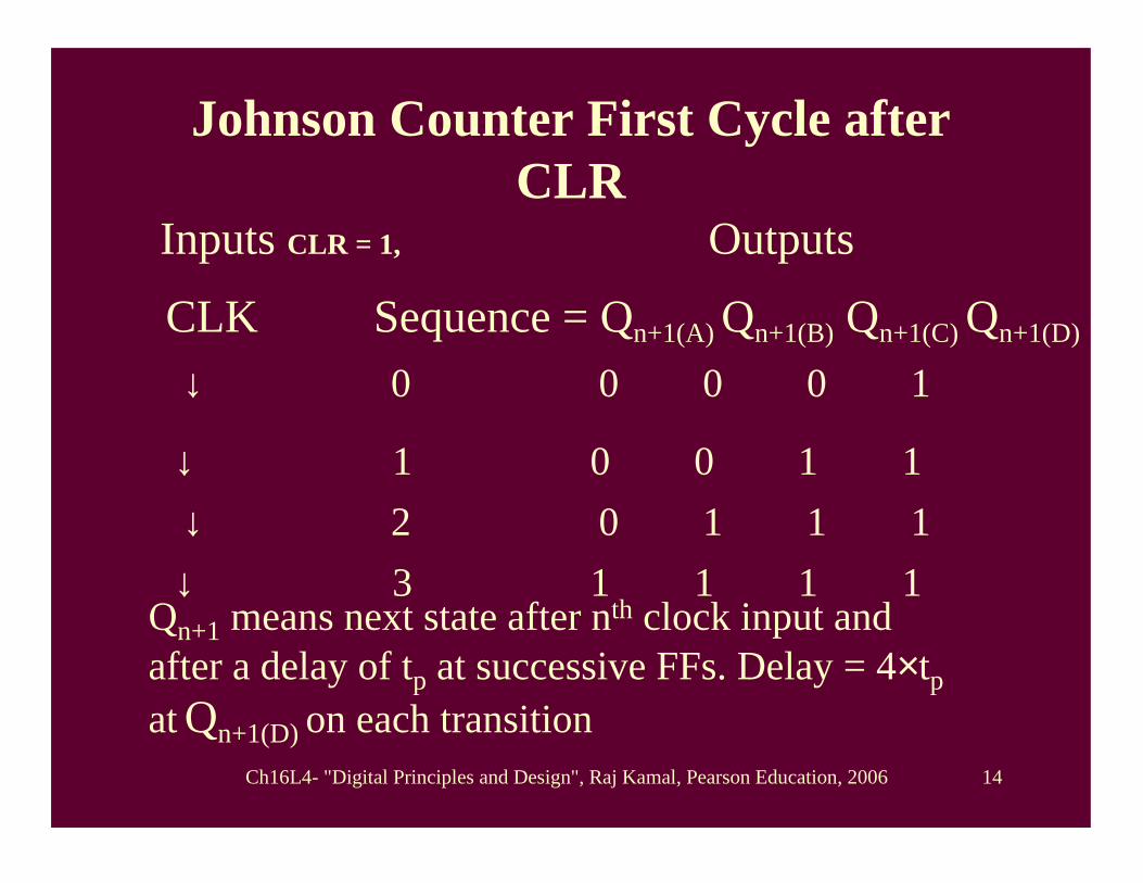
Johnson Counter First Cycle after CLR
Inputs CLR = 1, Outputs
CLK Sequence = Qn+1(A) Qn+1(B) Qn+1(C) Qn+1(D)
Qn+1 means next state after nth clock input and after a delay of tp at successive FFs. Delay = 4×tp at Qn+1(D) on each transition
↓ 0 0 0 0 1
↓ 1 0 0 1 1↓ 2 0 1 1 1↓ 3 1 1 1 1
Ch16L4- "Digital Principles and Design", Raj Kamal, Pearson Education, 2006 15
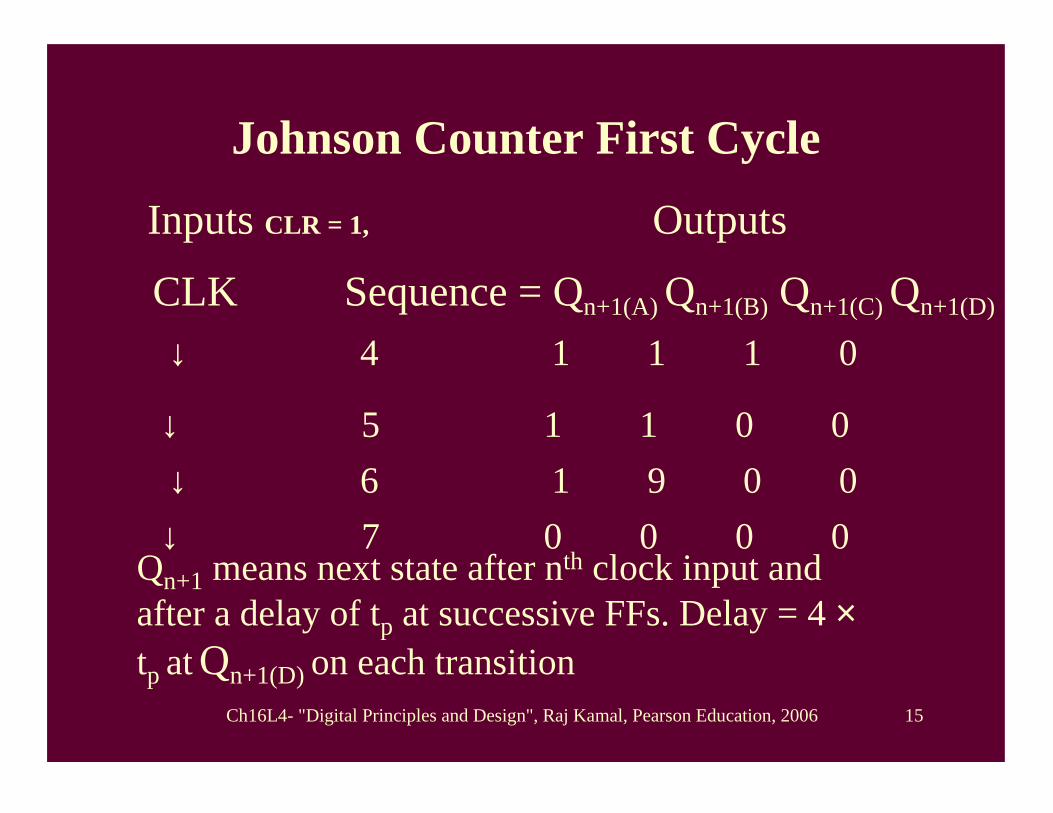
Johnson Counter First Cycle
Inputs CLR = 1, Outputs
CLK Sequence = Qn+1(A) Qn+1(B) Qn+1(C) Qn+1(D)
Qn+1 means next state after nth clock input and after a delay of tp at successive FFs. Delay = 4 ×tp at Qn+1(D) on each transition
↓ 4 1 1 1 0
↓ 5 1 1 0 0↓ 6 1 9 0 0↓ 7 0 0 0 0

Ch16L4- "Digital Principles and Design", Raj Kamal, Pearson Education, 2006 16
Johnson Counter QA is given as input to rightmost place instead of QD input in case of ring counter.
• When CLR = 0, all Qs and Ds of FFs = 0 cleared except the DD input at right most FF which sets to 1, as it connects QA.
• When CLR = 1, Johnson counting starts. On the clock edge, the QD = 1 left shifts to QCand since QA = 1 and connects to serial input at DD, QA = 1, QA = 1 and QC = 1.
Ch16L4- "Digital Principles and Design", Raj Kamal, Pearson Education, 2006 17
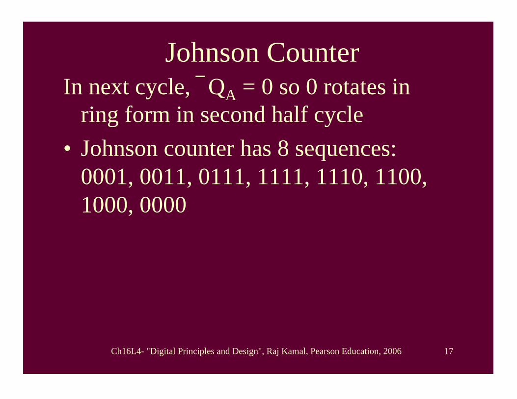
Johnson CounterIn next cycle, QA = 0 so 0 rotates in
ring form in second half cycle• Johnson counter has 8 sequences:
0001, 0011, 0111, 1111, 1110, 1100, 1000, 0000
Ch16L4- "Digital Principles and Design", Raj Kamal, Pearson Education, 2006 18
• Ring Counters•• Johnson Counter Johnson Counter •• Odd Sequencer Switch tail Odd Sequencer Switch tail
(Twisted Ring) Johnson counter(Twisted Ring) Johnson counter•• Even Sequencer Switch tail Even Sequencer Switch tail
(Twisted Ring) Johnson counter(Twisted Ring) Johnson counter
Outline
Ch16L4- "Digital Principles and Design", Raj Kamal, Pearson Education, 2006 19
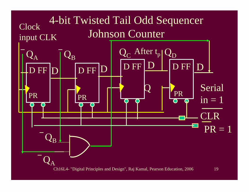
4-bit Twisted Tail Odd Sequencer Johnson Counter
D FFD FFD D FFD FF
QA
Q
CLR
Clock input CLK
After tp
D D D QB
QDQC
PR PR PR
PR = 1
Serial in = 1
QB
QA
Ch16L4- "Digital Principles and Design", Raj Kamal, Pearson Education, 2006 20
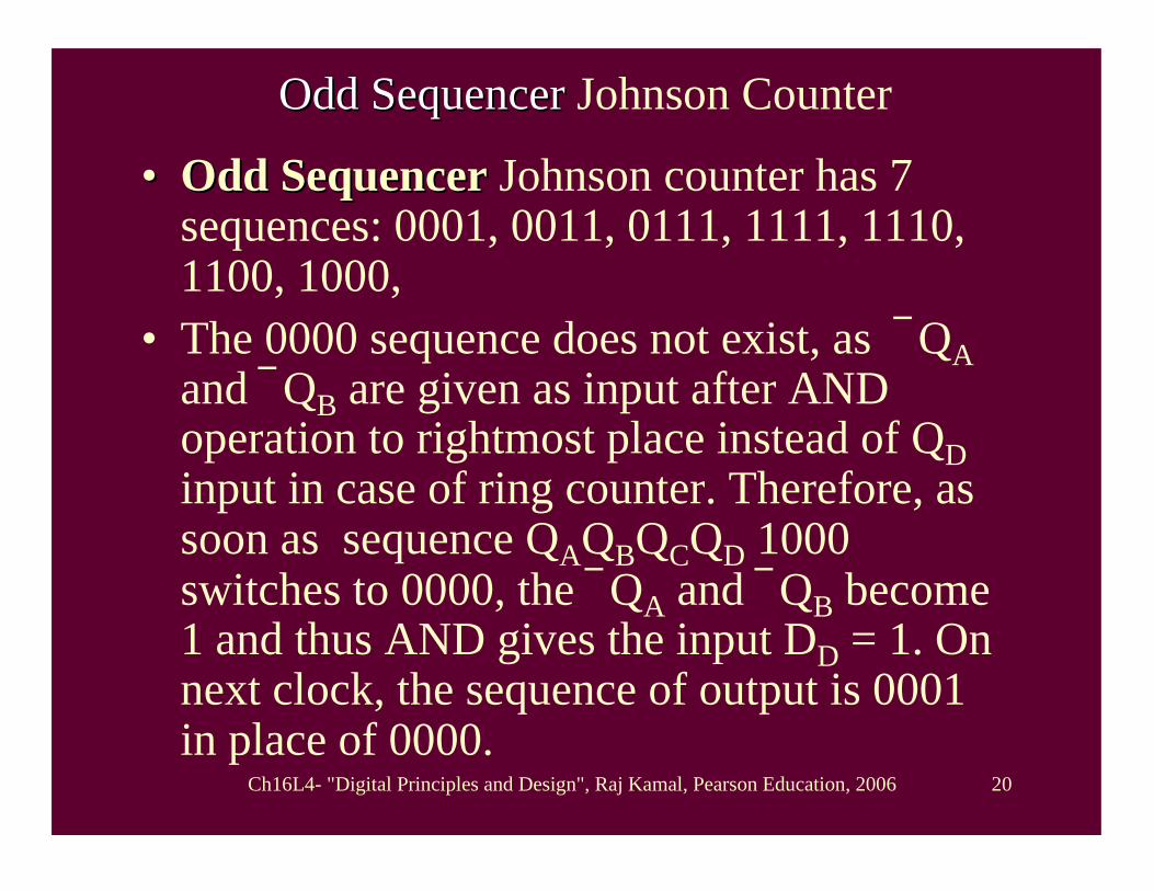
Odd SequencerOdd Sequencer Johnson Counter
•• Odd SequencerOdd Sequencer Johnson counter has 7 sequences: 0001, 0011, 0111, 1111, 1110, 1100, 1000,
• The 0000 sequence does not exist, as QAand QB are given as input after AND operation to rightmost place instead of QD input in case of ring counter. Therefore, as soon as sequence QAQBQCQD 1000 switches to 0000, the QA and QB become 1 and thus AND gives the input DD = 1. On next clock, the sequence of output is 0001 in place of 0000.

Ch16L4- "Digital Principles and Design", Raj Kamal, Pearson Education, 2006 21
State Diagram of (2n –1) Sequencer (n =4) Johnson Counter
S00001
S1
0011
S6
1000
S2
0111
S5
1100
S3
1111
S4
1110
Ch16L4- "Digital Principles and Design", Raj Kamal, Pearson Education, 2006 22
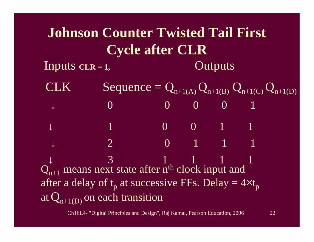
Johnson Counter Twisted Tail First Cycle after CLR
Inputs CLR = 1, Outputs
CLK Sequence = Qn+1(A) Qn+1(B) Qn+1(C) Qn+1(D)
Qn+1 means next state after nth clock input and after a delay of tp at successive FFs. Delay = 4×tp at Qn+1(D) on each transition
↓ 0 0 0 0 1
↓ 1 0 0 1 1↓ 2 0 1 1 1↓ 3 1 1 1 1
Ch16L4- "Digital Principles and Design", Raj Kamal, Pearson Education, 2006 23
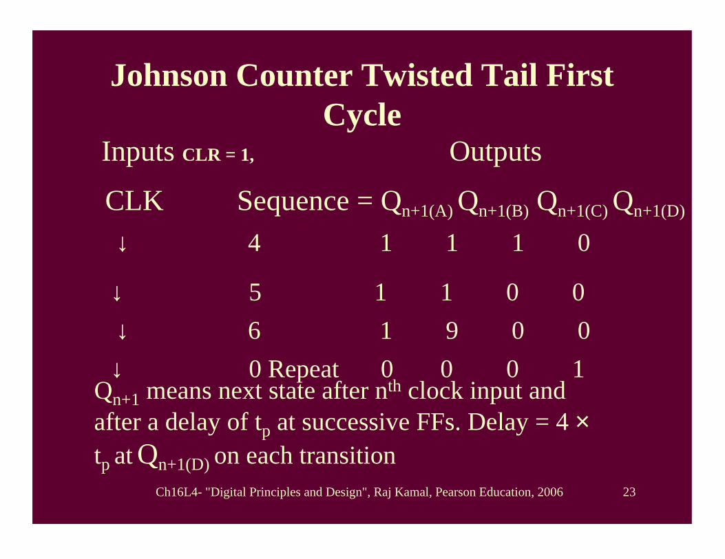
Johnson Counter Twisted Tail First Cycle
Inputs CLR = 1, Outputs
CLK Sequence = Qn+1(A) Qn+1(B) Qn+1(C) Qn+1(D)
Qn+1 means next state after nth clock input and after a delay of tp at successive FFs. Delay = 4 ×tp at Qn+1(D) on each transition
↓ 4 1 1 1 0
↓ 5 1 1 0 0↓ 6 1 9 0 0↓ 0 Repeat 0 0 0 1
Ch16L4- "Digital Principles and Design", Raj Kamal, Pearson Education, 2006 24
• Ring Counters•• Johnson Counter Johnson Counter • Odd Sequencer Switch tail
(Twisted Ring) Johnson counter•• Even Sequencer Switch tail Even Sequencer Switch tail
(Twisted Ring) Johnson counter(Twisted Ring) Johnson counter
Outline

Ch16L4- "Digital Principles and Design", Raj Kamal, Pearson Education, 2006 25
4-bit Twisted Tail Even Sequencer Johnson Counter
D FFD FFD D FFD FF
QA
Q
CLR
Clock input CLK
After tp
D D D QB
QDQC
PR PR PR
PR = 1
Serial in = 1
QB
QA
QB
QA

Ch16L4- "Digital Principles and Design", Raj Kamal, Pearson Education, 2006 26
Even SequencerEven Sequencer Johnson Counter
•• Even SequencerEven Sequencer Johnson counter has 6 sequences: 0001, 0011, 0111, 1110, 1100, 1000,
• The 1111 and 0000 sequence do not exist, as QA and QB ,and QA and QBare given as inputs after two AND operations to rightmost place instead of QD input in case of ring counter.
Ch16L4- "Digital Principles and Design", Raj Kamal, Pearson Education, 2006 27
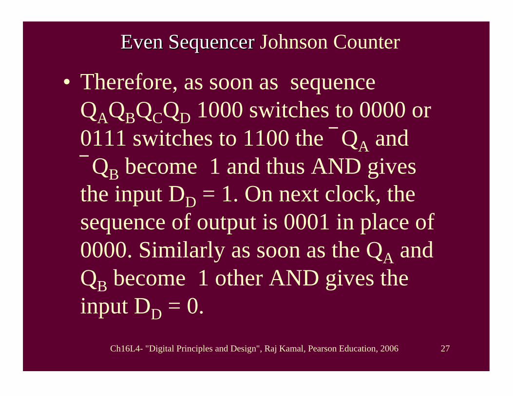
Even SequencerEven Sequencer Johnson Counter
• Therefore, as soon as sequence QAQBQCQD 1000 switches to 0000 or 0111 switches to 1100 the QA and QB become 1 and thus AND gives the input DD = 1. On next clock, the sequence of output is 0001 in place of 0000. Similarly as soon as the QA and QB become 1 other AND gives the input DD = 0.

Ch16L4- "Digital Principles and Design", Raj Kamal, Pearson Education, 2006 28
State Diagram of (2n –2) Sequencer (n =4) Johnson Counter
S00001
S1
0011
S6
1000
S2
0111
S5
1100
S4
1110
Ch16L4- "Digital Principles and Design", Raj Kamal, Pearson Education, 2006 29
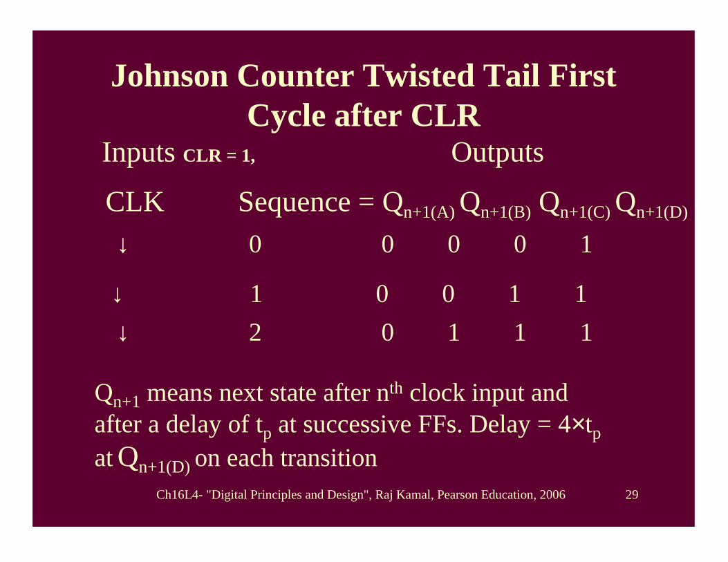
Johnson Counter Twisted Tail First Cycle after CLR
Inputs CLR = 1, Outputs
CLK Sequence = Qn+1(A) Qn+1(B) Qn+1(C) Qn+1(D)
Qn+1 means next state after nth clock input and after a delay of tp at successive FFs. Delay = 4×tp at Qn+1(D) on each transition
↓ 0 0 0 0 1
↓ 1 0 0 1 1↓ 2 0 1 1 1

Ch16L4- "Digital Principles and Design", Raj Kamal, Pearson Education, 2006 30
Johnson Counter Twisted Tail First Cycle
Inputs CLR = 1, Outputs
CLK Sequence = Qn+1(A) Qn+1(B) Qn+1(C) Qn+1(D)
Qn+1 means next state after nth clock input and after a delay of tp at successive FFs. Delay = 4 ×tp at Qn+1(D) on each transition
↓ 3 1 1 1 0
↓ 4 1 1 0 0↓ 5 1 0 0 0↓ 0 Repeat 0 0 0 1
Ch16L4- "Digital Principles and Design", Raj Kamal, Pearson Education, 2006 31
Summary
Ch16L4- "Digital Principles and Design", Raj Kamal, Pearson Education, 2006 32
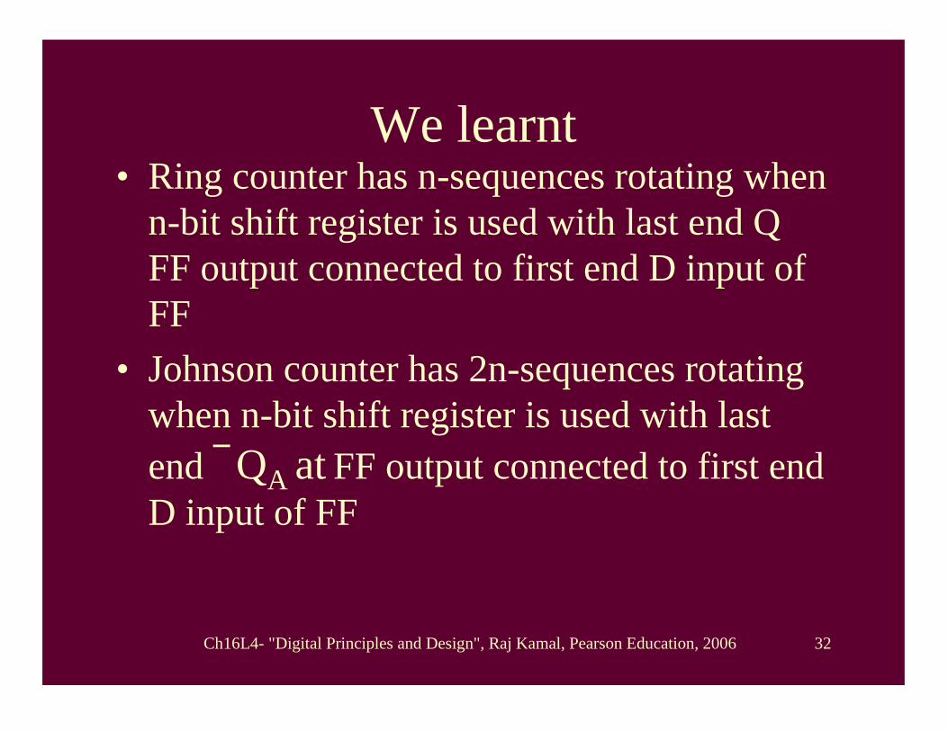
We learnt • Ring counter has n-sequences rotating when
n-bit shift register is used with last end Q FF output connected to first end D input of FF
• Johnson counter has 2n-sequences rotating when n-bit shift register is used with last end QA at FF output connected to first end D input of FF

Ch16L4- "Digital Principles and Design", Raj Kamal, Pearson Education, 2006 33
We learnt • Johnson counter twisted has (2n–1) sequences
rotating when n-bit shift register is used with last two QA and QB ANDed and connected to first end D input of FF
• Johnson counter twisted has (2n–2) sequences rotating when n-bit shift register is used with last two QA and QB ANDed and connected through OR gate to first end D input of FF and also last two QA and QB NANDed and connected through OR gate to first end D input of FF

Ch16L4- "Digital Principles and Design", Raj Kamal, Pearson Education, 2006 34
End of Lesson 4
RING AND JOHNSON RING AND JOHNSON COUNTERS COUNTERS
Ch16L4- "Digital Principles and Design", Raj Kamal, Pearson Education, 2006 35
THANK YOUTHANK YOU