Digital Clock with MM5314N.docx
9
Digital Clock with MM5314N
-
Upload
somnath-khamaru -
Category
Documents
-
view
112 -
download
4
description
new exciting
Transcript of Digital Clock with MM5314N.docx

Digital Clock with MM5314N
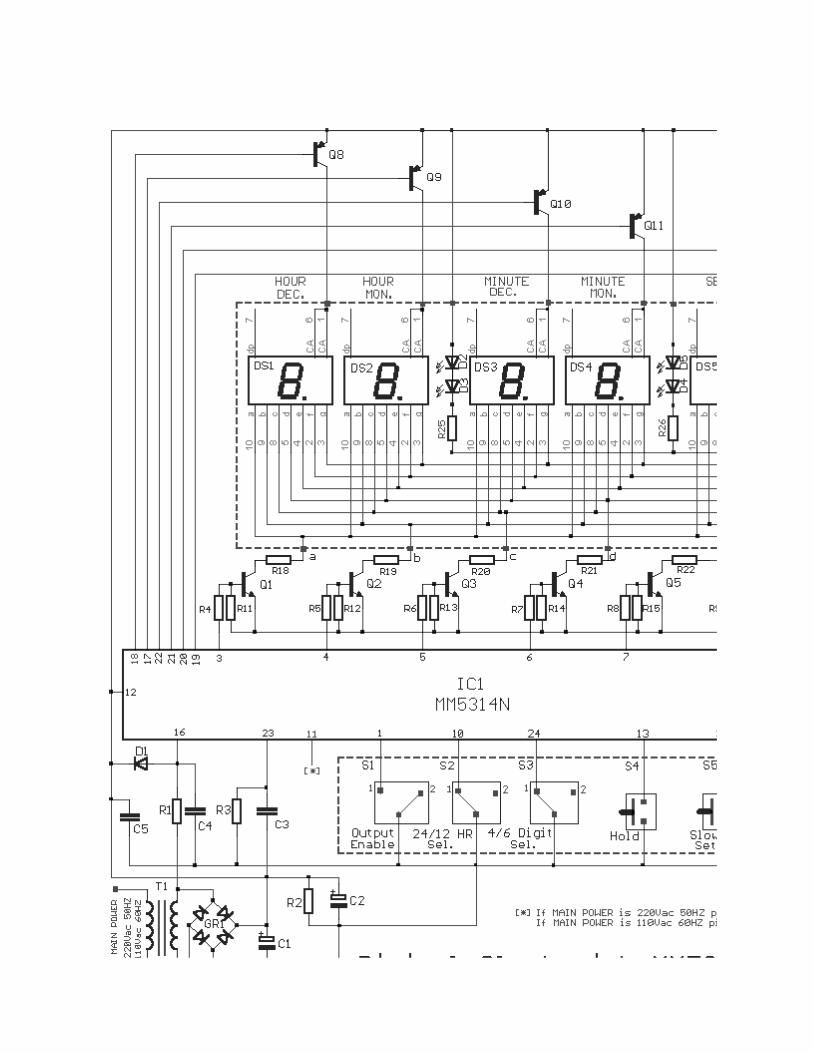
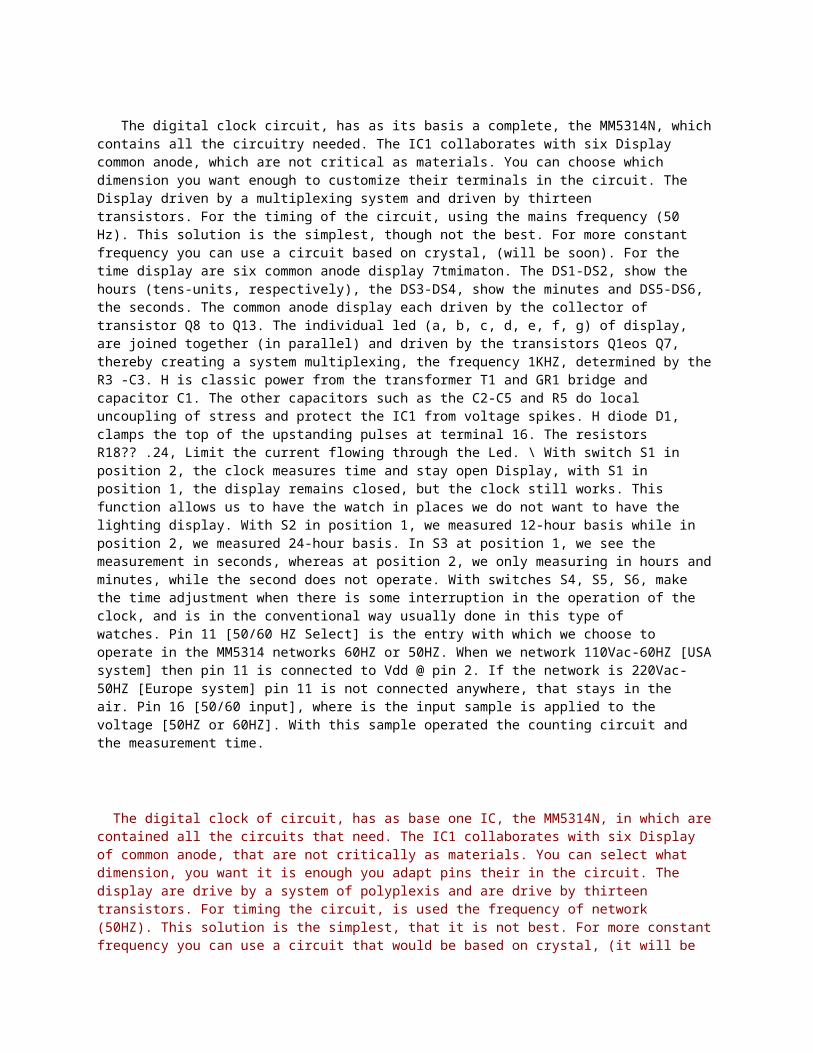
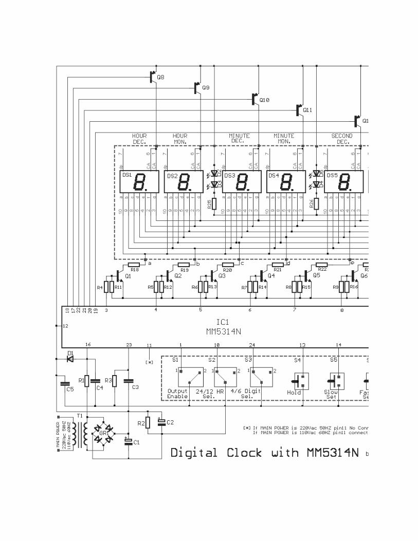
The digital clock circuit, has as its basis a complete, the MM5314N, which contains all the circuitry needed. The IC1 collaborates with six Display common anode, which are not critical as materials. You can choose which dimension you want enough to customize their terminals in the circuit. The Display driven by a multiplexing system and driven by thirteen transistors. For the timing of the circuit, using the mains frequency (50 Hz). This solution is the simplest, though not the best. For more constant frequency you can use a circuit based on crystal, (will be soon). For the time display are six common anode display 7tmimaton. The DS1-DS2, show the hours (tens-units, respectively), the DS3-DS4, show the minutes and DS5-DS6, the seconds. The common anode display each driven by the collector of transistor Q8 to Q13. The individual led (a, b, c, d, e, f, g) of display, are joined together (in parallel) and driven by the transistors Q1eos Q7, thereby creating a system multiplexing, the frequency 1KHZ, determined by the R3 -C3. H is classic power from the transformer T1 and GR1 bridge and capacitor C1. The other capacitors such as the C2-C5 and R5 do local uncoupling of stress and protect the IC1 from voltage spikes. H diode D1, clamps the top of the upstanding pulses at terminal 16. The resistors R18?? .24, Limit the current flowing through the Led. \ With switch S1 in position 2, the clock measures time and stay open Display, with S1 in position 1, the display remains closed, but the clock still works. This function allows us to have the watch in places we do not want to have the lighting display. With S2 in position 1, we measured 12-hour basis while in position 2, we measured 24-hour basis. In S3 at position 1, we see the measurement in seconds, whereas at position 2, we only measuring in hours and minutes, while the second does not operate. With switches S4, S5, S6, make the time adjustment when there is some interruption in the operation of the clock, and is in the conventional way usually done in this type of watches. Pin 11 [50/60 HZ Select] is the entry with which we choose to operate in the MM5314 networks 60HZ or 50HZ. When we network 110Vac-60HZ [USA system] then pin 11 is connected to Vdd @ pin 2. If the network is 220Vac-50HZ [Europe system] pin 11 is not connected anywhere, that stays in the air. Pin 16 [50/60 input], where is the input sample is applied to the voltage [50HZ or 60HZ]. With this sample operated the counting circuit and the measurement time.
The digital clock of circuit, has as base one IC, the MM5314N, in which are contained all the circuits that need. The IC1 collaborates with six Display of common anode, that are not critically as materials. You can select what dimension, you want it is enough you adapt pins their in the circuit. The display are drive by a system of polyplexis and are drive by thirteen transistors. For timing the circuit, is used the frequency of network (50HZ). This solution is the simplest, that it is not best. For more constant frequency you can use a circuit that would be based on crystal, (it will be given shortly). For the clue of hour are used six display of 7 element common anode. The DS1-DS2, show the hours (decades-unit respectively), the DS3-DS4, show the minutes and DS5-DS6, the seconds. The common anode, for each display is drive by the collector of transistors Q8 until Q13. Individual led (a, b, c, d, e, f, g) the display, they are linked between them (parallel) and are drive by the transistors Q1 .. Q7, creating thus a system multiplexing, to frequency 1KHZ, that is determined by the R3-C3. The power supply is a classic circuit, from T1 and GR1, C1. The remainder capacitors as the C2-C5 and the R5 make local unyoke of voltage and protect the IC1 from peaks of voltage. The diode D1, limit the top, of rectified vibrations in the pin 16. Resistances R18 ... 24, limit the current that leak the led. With switch S1 in place 2, the clock measures the time and the display remains openly, with the S1 in place 1, the display they remain closed, the clock however continues working. This operation us allows to have the clock in spaces that we do not want exists the lighting of display. With the S2 in place 1, we have measurement in 12-hours base while in place 2, we have measurement in 24-hours base. With the S3 in place 1, we see the measurement in seconds, while in place 2, we only

see the measurement in hours and minutes, while the seconds do not function. With switches S4, S5, S6, we make the regulation of hour when exists some interruption in the operation of clock, and becomes with the classic way that usually becomes in this type the clocks. The pin 11 [50/60 of HZ Select] is the input with which we select the operation of MM5314 in main voltage frequency 60HZ or 50HZ. When we have main voltage 110Vac-60HZ [USA system] then the pin 11 is connected in Vss @ pin 2. If the main voltage is 220Vac - 50HZ [Europe system] the pin 11 is not connected nowhere, remain that is to say in air. Pin 16 [50/60 input], is the input, where is applied sample from the main voltage [50HZ or 60HZ]. With this sample function the counter circuits and become the measurement of time. Thus if you have 220Vac/50HZ, then the pin 11 remains void. If you have 110V/60HZ, then the pin 11 it's connected in Vss @ pin 2.
Notice ** : The MM5314N rather been withdrawn from the Manufacture, IT Likely exist somewhere in Small Quantities. I Don;; Have nobody t he information Round .
Part List
R1 = 100Kohms C1 = 2200uF 25V D1 = 1N4148R2 = 47Kohms C2 = 100uF 25V GR1 = 4X1N4002R3 = 100Kohms C3 = 18nF 100V polyester S1 ... 3 = 1X2 mini switch
R4 ..... 10 = 2.2Kohms C4-5 = 10nF ceramic OR polyester
S4 ... 6 = Push Button normal open
R11 ..... 17 = 10Kohms 7 .... Q1 = BC550 T1 = 220V AC/12V 1AR18 ..... 24-25-26 = 220 ohms 0W5
Q8 .... the 13th = BC560DS1 .... DS7 = Display the 7th segmens Common Anode
R25-26 = 1.2Kohms 0W5 IC1 = MM5314N *** [See Notice]
Sam Electronic Circuits on the 10th / 01
[ Home ] [ My Database ] [ My Guestbook ]
Digital Clock with MM5314N

The digital clock circuit, has as its basis a complete, the MM5314N, which contains all the
circuitry needed. The IC1 collaborates with six Display common anode, which are not critical as materials. You can choose which dimension you want enough to customize their terminals in the circuit. The Display driven by a multiplexing system and driven by thirteen transistors. For the timing of the circuit, using the mains frequency (50 Hz). This solution is the simplest, though not the best. For more constant frequency you can use a circuit based on crystal, (will be soon). For the time display are six common anode display 7tmimaton. The DS1-DS2, show the hours (tens-units, respectively), the DS3-DS4, show the minutes and DS5-DS6, the seconds. The common anode display each driven by the collector of transistor Q8 to Q13. The individual led (a, b, c, d, e, f, g) of display, are joined together (in parallel) and driven by the transistors Q1eos Q7, thereby creating a system multiplexing, the frequency 1KHZ, determined by the R3 -C3. H is classic power from the transformer T1 and GR1 bridge and capacitor C1. The other capacitors such as the C2-C5 and R5 do local uncoupling of stress and protect the IC1 from voltage spikes. H diode D1, clamps the top of the upstanding pulses at terminal 16. The resistors R18?? .24, Limit the current flowing through the Led. \ With switch S1 in position 2, the clock measures time and stay open Display, with S1 in position 1, the display remains closed, but the clock still works. This function allows us to have the watch in places we do not want to have the lighting display. With S2 in position 1, we measured 12-hour basis while in position 2, we measured 24-hour basis. In S3 at position 1, we see the measurement in seconds, whereas at position 2, we only measuring in hours and minutes, while the second does not operate. With switches S4, S5, S6, make the time adjustment when there is some interruption in the operation of the clock, and is in the conventional way usually done in this type of watches. Pin 11 [50/60 HZ Select] is the entry with which we choose to operate in the MM5314 networks 60HZ or 50HZ. When we network 110Vac-60HZ [USA system] then pin 11 is connected to Vdd @ pin 2. If the network is 220Vac-50HZ [Europe system] pin 11 is not connected anywhere, that stays in the air. Pin 16 [50/60 input], where is the input sample is applied to the voltage [50HZ or 60HZ]. With this sample operated the counting circuit and the measurement time.
The digital clock of circuit, has as base one IC, the MM5314N, in which are contained all the circuits that need. The IC1 collaborates with six Display of common anode, that are not critically as materials. You can select what dimension, you want it is enough you adapt pins their in the circuit. The display are drive by a system of polyplexis and are drive by thirteen transistors. For timing the circuit, is used the frequency of network (50HZ). This solution is the simplest, that it is not best. For more constant frequency you can use a circuit that would be based on crystal, (it will be given shortly). For the clue of hour are used six display of 7 element common anode. The DS1-DS2, show the hours (decades-unit respectively), the DS3-DS4, show the minutes and DS5-DS6, the seconds. The common anode, for each display is drive by the collector of transistors Q8 until Q13. Individual led (a, b, c, d, e, f, g) the display, they are linked between them (parallel) and are drive by the transistors Q1 .. Q7, creating thus a system multiplexing, to frequency 1KHZ, that is determined by the R3-C3. The power supply is a classic circuit, from T1 and GR1, C1. The remainder capacitors as the C2-C5 and the R5 make local unyoke of voltage and protect the IC1 from peaks of voltage. The diode D1, limit the top, of rectified vibrations in the pin 16. Resistances R18 ... 24, limit the current that leak the led. With switch S1 in place 2, the clock measures the time and the display remains openly, with the S1 in place 1, the display they remain closed, the clock however continues working. This operation us allows to have the clock in spaces that we do not want exists the lighting of display. With the S2 in place 1, we have measurement in 12-hours base while in place 2, we have measurement in 24-hours base. With the S3 in place 1, we see the measurement in seconds, while in place 2, we only see the measurement in hours and minutes, while the seconds do not function. With

switches S4, S5, S6, we make the regulation of hour when exists some interruption in the operation of clock, and becomes with the classic way that usually becomes in this type the clocks. The pin 11 [50/60 of HZ Select] is the input with which we select the operation of MM5314 in main voltage frequency 60HZ or 50HZ. When we have main voltage 110Vac-60HZ [USA system] then the pin 11 is connected in Vss @ pin 2. If the main voltage is 220Vac - 50HZ [Europe system] the pin 11 is not connected nowhere, remain that is to say in air. Pin 16 [50/60 input], is the input, where is applied sample from the main voltage [50HZ or 60HZ]. With this sample function the counter circuits and become the measurement of time. Thus if you have 220Vac/50HZ, then the pin 11 remains void. If you have 110V/60HZ, then the pin 11 it's connected in Vss @ pin 2.
Notice ** : The MM5314N rather been withdrawn from the Manufacture, IT Likely exist somewhere in Small Quantities. I Don;; Have nobody t he information Round .
Part List
R1 = 100Kohms C1 = 2200uF 25V D1 = 1N4148R2 = 47Kohms C2 = 100uF 25V GR1 = 4X1N4002R3 = 100Kohms C3 = 18nF 100V polyester S1 ... 3 = 1X2 mini switch
R4 ..... 10 = 2.2Kohms C4-5 = 10nF ceramic OR polyester
S4 ... 6 = Push Button normal open
R11 ..... 17 = 10Kohms 7 .... Q1 = BC550 T1 = 220V AC/12V 1AR18 ..... 24-25-26 = 220 ohms 0W5
Q8 .... the 13th = BC560DS1 .... DS7 = Display the 7th segmens Common Anode
R25-26 = 1.2Kohms 0W5 IC1 = MM5314N *** [See Notice]
Sam Electronic Circuits on the 10th / 01
[ Home ] [ My Database ] [ My Guestbook ]