Digital Amplifi ed Indoor/Outdoor Antenna · Digital Amplifi ed Indoor/Outdoor Antenna User’s...
11
1 ENGLISH FCC Statement This device complies with part 15 of the FCC Rules. Operation is subject to the following two conditions: (1) This device may not cause harmful interference, and (2) this device must accept any interference received, including interference that may cause undesired operation. This equipment has been tested and found to comply with the limits for a Class B Digital Device, pursuant to Part 15 of the FCC Rules. These limits are designed to this equipment generates, uses, and can radiate radio frequency energy and, if not installed and used in accordance with the instructions, may cause harmful interference to radio communications. However, there is no guarantee that interference will not occur in a particular installation. If this equipment does cause harmful interference to radio or television reception, which can be determined by turning the radio or television off and on, the user is encouraged to try to correct interference by one or more of the following measures: • Reorient or relocate the receiving antenna. • Increase the separation between the equipment and receiver. • Connect the equipment into an outlet on another circuit. • Consult the dealer or an experienced radio/TV technician for help. Caution: Any changes or modifications not expressly approved by the party responsible for compliance could void the user’s authority to operate this equipment. Industry Canada Regulatory Information CAN ICES-3 (B)/NMB-3 (B) Avis d’Industrie Canada CAN ICES-3 (B)/NMB-3 (B) Important: This power adapter should be plugged in so that it stays vertical or lays flat. ANT702F Digital Amplified Indoor/Outdoor Antenna User’s Guide Getting Started Remove the antenna and the hardware bag from package. Make sure the following parts are in the package: • Antenna • Amplifier Insert • Power Adapter • Mounting Base • Mounting Arm • Hardware bag: (2) U-Bolts (2) Clamps (4) Plastic Anchors (4) Wood screws (4) Washer Nuts (1) Coaxial cable (2) Bolts BEFORE YOU START!!! Please read the IMPORTANT SAFETY INFORMATION sheet included in this package. ENGLISH
Transcript of Digital Amplifi ed Indoor/Outdoor Antenna · Digital Amplifi ed Indoor/Outdoor Antenna User’s...
1
ENG
LISH
FCC StatementThis device complies with part 15 of the FCC Rules. Operation is subject to the following two conditions: (1) This device may not cause harmful interference, and (2) this device must accept any interference received, including interference that may cause undesired operation.This equipment has been tested and found to comply with the limits for a Class B Digital Device, pursuant to Part 15 of the FCC Rules. These limits are designed to this equipment generates, uses, and can radiate radio frequency energy and, if not installed and used in accordance with the instructions, may cause harmful interference to radio communications. However, there is no guarantee that interference will not occur in a particular installation. If this equipment does cause harmful interference to radio or television reception, which can be determined by turning the radio or television off and on, the user is encouraged to try to correct interference by one or more of the following measures: • Reorient or relocate the receiving antenna. • Increase the separation between the equipment and receiver. • Connect the equipment into an outlet on another circuit. • Consult the dealer or an experienced radio/TV technician for help.Caution: Any changes or modifications not expressly approved by the party responsible for compliance could void the user’s authority to operate this equipment.
Industry Canada Regulatory InformationCAN ICES-3 (B)/NMB-3 (B)
Avis d’Industrie CanadaCAN ICES-3 (B)/NMB-3 (B)Important: This power adapter should be plugged in so that it stays vertical or lays flat.
ANT702FDigital Amplifi ed Indoor/Outdoor AntennaUser’s Guide
Getting Started Remove the antenna and the hardware bag from package. Make sure the following parts are in the package:
• Antenna• Amplifi er Insert • Power Adapter • Mounting Base • Mounting Arm• Hardware bag:
(2) U-Bolts (2) Clamps(4) Plastic Anchors (4) Wood screws(4) Washer Nuts (1) Coaxial cable(2) Bolts
BEFORE YOU START!!!Please read the IMPORTANT SAFETY INFORMATION sheet included in this package.
ENG
LISH
2
Mounting the AntennaThe antenna mounting base and arm give you fl exibility in mounting the antenna. The antenna can be mounted:
• To a surface, such as a rooftop, eaves, siding, or rafters in an attic
-OR-
• To a standard mast (not included)
WARNING: Never hang anything from the antenna; never attach foreign objects to the antenna.
NOTES: Do not install the antenna on any metal surface, including aluminum siding. Mounting on a metal surface will seriously degrade reception quality.
In most cases, the antenna provides the best performance when mounted outdoors in a high location (such as on the roof or high up on the side of your house). The antenna can also be mounted in an attic or indoors.
Finding the Right LocationBefore you mount the antenna, consider the following factors in reception performance:
• The antenna performs best when mounted vertically
• The antenna should be mounted on the side of your house that faces most of your local broadcast towers. Visit www.antennaweb.org to see the locations of your local broadcast towers.
• The higher the elevation of the antenna, the better the reception performance will be.
3
ENG
LISH
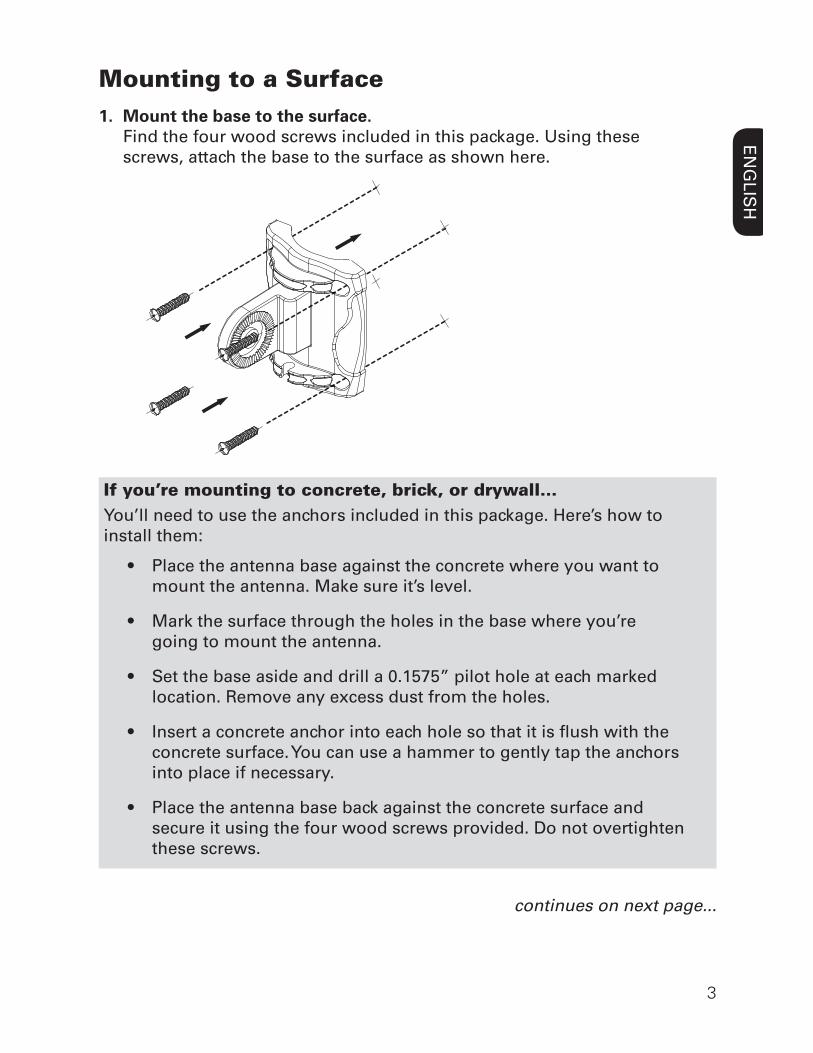
Mounting to a Surface1. Mount the base to the surface.
Find the four wood screws included in this package. Using these screws, attach the base to the surface as shown here.
If you’re mounting to concrete, brick, or drywall...You’ll need to use the anchors included in this package. Here’s how to install them:
• Place the antenna base against the concrete where you want to mount the antenna. Make sure it’s level.
• Mark the surface through the holes in the base where you’re going to mount the antenna.
• Set the base aside and drill a 0.1575” pilot hole at each marked location. Remove any excess dust from the holes.
• Insert a concrete anchor into each hole so that it is fl ush with the concrete surface. You can use a hammer to gently tap the anchors into place if necessary.
• Place the antenna base back against the concrete surface and secure it using the four wood screws provided. Do not overtighten these screws.
continues on next page...
4
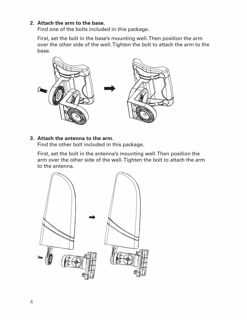
2. Attach the arm to the base. Find one of the bolts included in this package.
First, set the bolt in the base’s mounting well. Then position the arm over the other side of the well. Tighten the bolt to attach the arm to the base.
3. Attach the antenna to the arm. Find the other bolt included in this package.
First, set the bolt in the antenna’s mounting well. Then position the arm over the other side of the well. Tighten the bolt to attach the arm to the antenna.
5
ENG
LISH
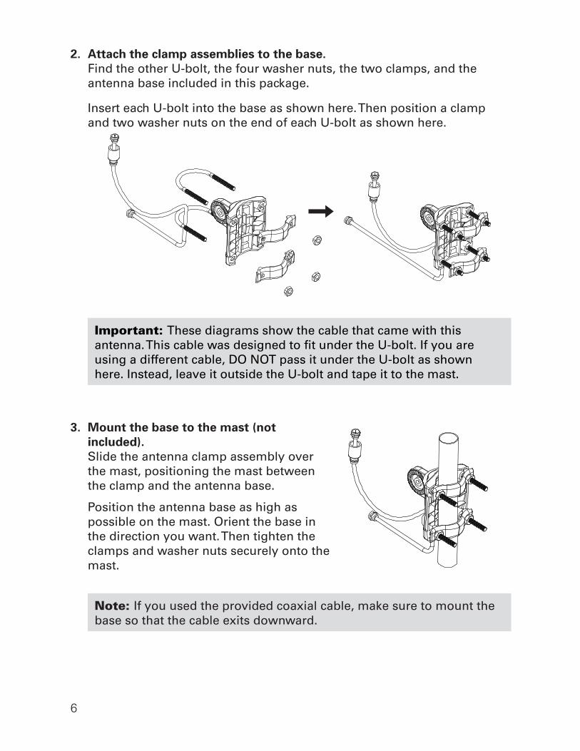
1. If you’re using the provided coaxial cable, thread it through one of the U-bolts.
Find the coaxial cable and one of the U-bolts included in this package. Thread the coaxial cable through the U-bolt as shown here.
IMPORTANT: If you’re not using the coaxial cable that came with this antenna, skip step 1.
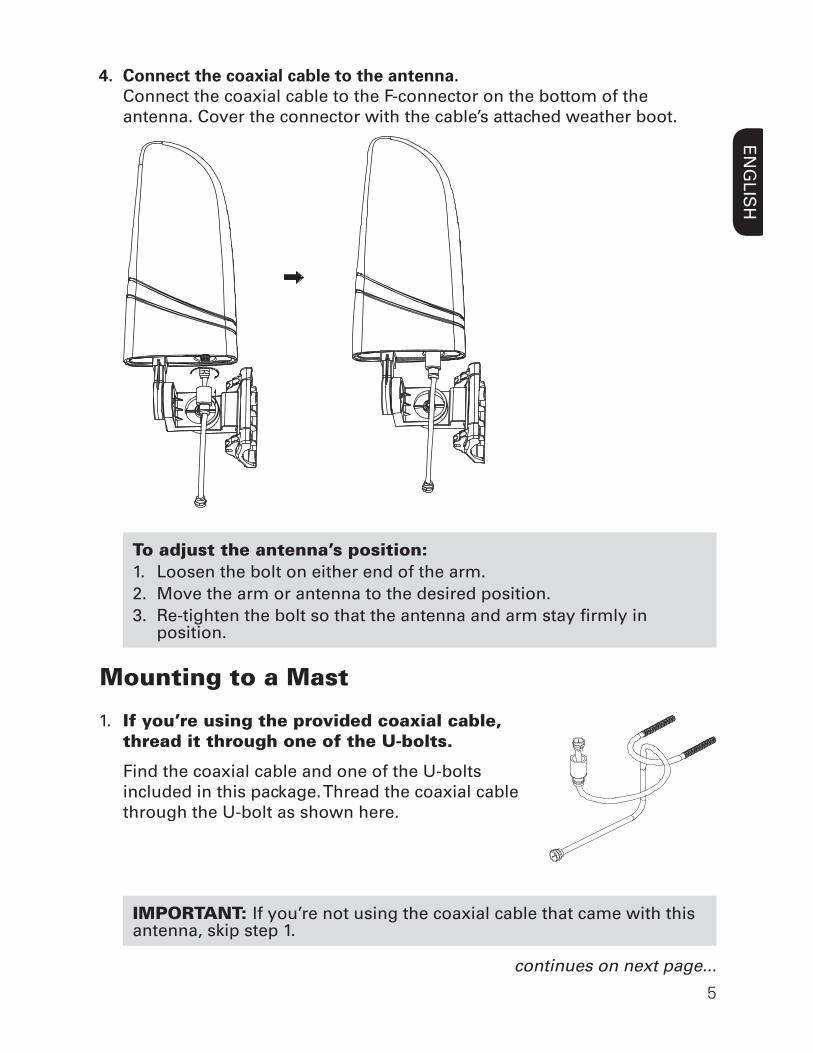
4. Connect the coaxial cable to the antenna. Connect the coaxial cable to the F-connector on the bottom of the
antenna. Cover the connector with the cable’s attached weather boot.
To adjust the antenna’s position: 1. Loosen the bolt on either end of the arm.2. Move the arm or antenna to the desired position.3. Re-tighten the bolt so that the antenna and arm stay fi rmly in
position.
continues on next page...
Mounting to a Mast
6
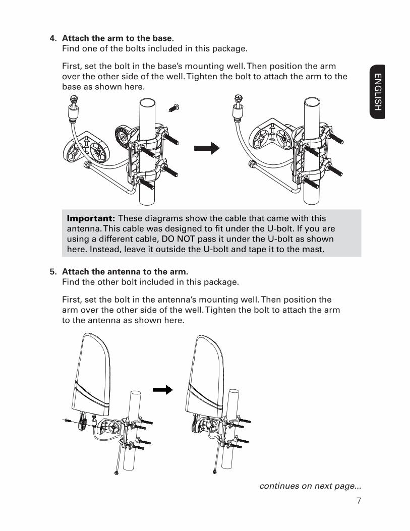
2. Attach the clamp assemblies to the base.Find the other U-bolt, the four washer nuts, the two clamps, and the antenna base included in this package.
Insert each U-bolt into the base as shown here. Then position a clamp and two washer nuts on the end of each U-bolt as shown here.
Important: These diagrams show the cable that came with this antenna. This cable was designed to fi t under the U-bolt. If you are using a different cable, DO NOT pass it under the U-bolt as shown here. Instead, leave it outside the U-bolt and tape it to the mast.
3. Mount the base to the mast (not included).
Slide the antenna clamp assembly over the mast, positioning the mast between the clamp and the antenna base.
Position the antenna base as high as possible on the mast. Orient the base in the direction you want. Then tighten the clamps and washer nuts securely onto the mast.
Note: If you used the provided coaxial cable, make sure to mount the base so that the cable exits downward.
7
ENG
LISH
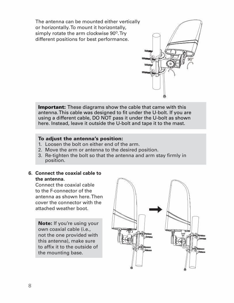
4. Attach the arm to the base.Find one of the bolts included in this package.
First, set the bolt in the base’s mounting well. Then position the arm over the other side of the well. Tighten the bolt to attach the arm to the base as shown here.
Important: These diagrams show the cable that came with this antenna. This cable was designed to fi t under the U-bolt. If you are using a different cable, DO NOT pass it under the U-bolt as shown here. Instead, leave it outside the U-bolt and tape it to the mast.
5. Attach the antenna to the arm.Find the other bolt included in this package.
First, set the bolt in the antenna’s mounting well. Then position the arm over the other side of the well. Tighten the bolt to attach the arm to the antenna as shown here.
continues on next page...
8
The antenna can be mounted either vertically or horizontally. To mount it horizontally, simply rotate the arm clockwise 90O. Try different positions for best performance.
Important: These diagrams show the cable that came with this antenna. This cable was designed to fi t under the U-bolt. If you are using a different cable, DO NOT pass it under the U-bolt as shown here. Instead, leave it outside the U-bolt and tape it to the mast.
To adjust the antenna’s position: 1. Loosen the bolt on either end of the arm.2. Move the arm or antenna to the desired position.3. Re-tighten the bolt so that the antenna and arm stay fi rmly in
position.
6. Connect the coaxial cable to the antenna.Connect the coaxial cable to the F-connector of the antenna as shown here. Then cover the connector with the attached weather boot.
Note: If you’re using your own coaxial cable (i.e., not the one provided with this antenna), make sure to affi x it to the outside of the mounting base.
90°
9
ENG
LISH
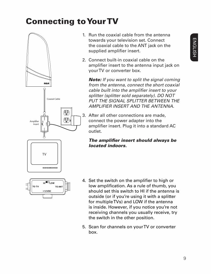
Connecting to Your TV1. Run the coaxial cable from the antenna
towards your television set. Connect the coaxial cable to the ANT jack on the supplied amplifi er insert.
2. Connect built-in coaxial cable on the amplifi er insert to the antenna input jack on your TV or converter box.
Note: If you want to split the signal coming from the antenna, connect the short coaxial cable built into the amplifi er insert to your splitter (splitter sold separately). DO NOT PUT THE SIGNAL SPLITTER BETWEEN THE AMPLIFIER INSERT AND THE ANTENNA.
3. After all other connections are made, connect the power adapter into the amplifi er insert. Plug it into a standard AC outlet.
The amplifi er insert should always be located indoors.
TV
Coaxial Cable
Ampli!erInsert
TO A
NT
TOTV
+12V
DCL OW
HI
TO ANTTO TV
+12VDC
LOWHI4. Set the switch on the amplifi er to high or
low amplifi cation. As a rule of thumb, you should set this switch to HI if the antenna is outside (or if you’re using it with a splitter for multiple TVs) and LOW if the antenna is inside. However, if you notice you’re not receiving channels you usually receive, try the switch in the other position.
5. Scan for channels on your TV or converter box.
10
Water Damage Prevention:
At the point where your coaxial cable lead enters the house, you should allow for some slack in the coaxial cable as a “drip loop.” This will prevent moisture from running down the coaxial cable and entering the house.Run the coaxial cable approximately six inches below the wall entry point and then turn it upwards towards this spot. Any moisture that accumulates on the coaxial cable will drip off in the bend instead of running into the house. You should seal the point where the cable enters your home with a rubber weather insulator or silicone caulking (not included). An “F” connector wall plate can be used inside the home to cover the inside portion of the hole. You can typically fi nd an “F” connector wall plate at any local electronics or hardware store.
11
ENG
LISH
12 Month Limited Warranty VOXX Accessories Corporation (the “Company”) warrants to the original retail purchaser of this product that should this product or any part thereof, under normal use and conditions, be proven defective in material or workmanship within 12 months from the date of original purchase, such defect(s) will be repaired or replaced (at the Company’s option) without charge for parts and repair labor. To obtain repair or replacement within the terms of this Warranty, the product along with any accessories included in the original packaging is to be delivered with proof of warranty coverage (e.g. dated bill of sale), specifi cation of defect(s), transportation prepaid, to the Company at the address shown below. Do not return this product to the Retailer. This Warranty is not transferable and does not cover product purchased, serviced or used outside the United States or Canada. The warranty does not extend to the elimination of externally generated static or noise. This Warranty does not apply to costs incurred for installation, removal or reinstallation of the product, or, if in the Company’s opinion, the product has been damaged through acts of nature, alteration, improper installation, mishandling, misuse, neglect, or accident. This warranty does not cover damage caused by an AC adapter not provided with the product. THE EXTENT OF THE COMPANY’S LIABILITY UNDER THIS WARRANTY IS LIMITED TO THE REPAIR OR REPLACEMENT PROVIDED ABOVE AND, IN NO EVENT, SHALL THE COMPANY’S LIABILITY EXCEED THE PURCHASE PRICE PAID BY PURCHASER FOR THE PRODUCT. This Warranty is in lieu of all other express warranties or liabilities. ANY IMPLIED WARRANTIES, INCLUDING ANY IMPLIED WARRANTY OF MERCHANTABILITY OR FITNESS FOR A PARTICULAR PURPOSE, SHALL BE LIMITED TO DURATION OF THIS WARRANTY. ANY ACTION FOR BREACH OF ANY WARRANTY HEREUNDER, INCLUDING ANY IMPLIED WARRANTY, MUST BE BROUGHT WITHIN A PERIOD OF 24 MONTHS FROM THE DATE OF ORIGINAL PURCHASE. IN NO CASE SHALL THE COMPANY BE LIABLE FOR ANY CONSEQUENTIAL OR INCIDENTAL DAMAGES WHATSOEVER. No person or representative is authorized to assume for the Company any liability other than expressed herein in connection with the sale of this product. Some states/provinces do not allow limitations on how long an implied warranty lasts or the exclusion or limitation of incidental or consequential damage so the above limitations or exclusions may not apply to you. This Warranty gives you specifi c legal rights and you may also have other rights which vary from state/province to state/province. U.S.A.: Audiovox Return Center, 150 Marcus Blvd., Hauppauge, NY 11788 CANADA: Audiovox Return Center, c/o Genco, 6685 Kennedy Road, Unit #3 Door 14, Mississauga Ontario L5T 3A5
©2013 VOXX Accessories Corporation 3502 Woodview Trace, Suite 220, Indianapolis, IN 46268
ANT702F NA IB 01