
Digipulse 450i Power Source - esabna.com - f15-999/digipulse 450i... · protective non-flammable...
36
F-15-014-F June, 2003 INSTRUCTION MANUAL Digipulse 450i Power Source This manual provides installation and operation instructions for the following Digipulse 450i cutting package: ESAB P/N 31120 - 208/230/460 V ac, 1 or 3 phase ESAB P/N 31238 - 575 V ac, 3 phase, 60 Hz (refer to supplement F-15-015) ESAB P/N 31690 - 220/380/415 V ac, 3 phase, 50 Hz (refer to supplement F-15-039) These INSTRUCTIONS are for experienced operators. If you are not fully familiar with the principles of operation and safe practices for electric welding equipment, we urge you to read our booklet, "Precautions and Safe Practices for Arc Welding, Cutting, and Gouging," Form 52-529. Do NOT permit untrained persons to install, operate, or maintain this equipment. Do NOT attempt to install or operate this equipment until you have read and fully understand these instructions. If you do not fully understand these instructions, contact your supplier for further information. Be sure to read the Safety Precautions before installing or operating this equipment. Be sure this information reaches the operator. You can get extra copies through your supplier.
-
Upload
truongcong -
Category
Documents
-
view
225 -
download
0
Transcript of Digipulse 450i Power Source - esabna.com - f15-999/digipulse 450i... · protective non-flammable...

F-15-014-FJune, 2003
INSTRUCTION MANUAL
Digipulse 450iPower Source
This manual provides installation and operation instructions for the following Digipulse 450i cutting package:
ESAB P/N 31120 - 208/230/460 V ac, 1 or 3 phaseESAB P/N 31238 - 575 V ac, 3 phase, 60 Hz (refer to supplement F-15-015)ESAB P/N 31690 - 220/380/415 V ac, 3 phase, 50 Hz (refer to supplement F-15-039)
These INSTRUCTIONS are for experienced operators. If you are not fully familiar with the principles of operation andsafe practices for electric welding equipment, we urge you to read our booklet, "Precautions and Safe Practices forArc Welding, Cutting, and Gouging," Form 52-529. Do NOT permit untrained persons to install, operate, or maintainthis equipment. Do NOT attempt to install or operate this equipment until you have read and fully understand theseinstructions. If you do not fully understand these instructions, contact your supplier for further information. Be sureto read the Safety Precautions before installing or operating this equipment.
Be sure this information reaches the operator.You can get extra copies through your supplier.
2
USER RESPONSIBILITY
This equipment will perform in conformity with the description thereof contained in this manual and accompanyinglabels and/or inserts when installed, operated, maintained and repaired in accordance with the instructions pro-vided. This equipment must be checked periodically. Defective equipment should not be used. Parts that arebroken, missing, worn, distorted or contaminated should be replaced immediately. Should such repair or replace-ment become necessary, the manufacturer recommends that a telephone or written request for service advice bemade to the Authorized Distributor from whom purchased.
This equipment or any of its parts should not be altered without the prior written approval of the manufacturer. Theuser of this equipment shall have the sole responsibility for any malfunction which results from improper use, faultymaintenance, damage, improper repair or alteration by anyone other than the manufacturer or a service facilitydesignated by the manufacturer.
TABLE OF CONTENTS
SECTION TITLE PAGEPARAGRAPH
SECTION 1 DESCRIPTION ................................................................................................. 51.1 Introduction ....................................................................................................... 51.2 Specifications .................................................................................................... 5
SECTION 2 INSTALLATION................................................................................................ 62.1 General ............................................................................................................. 62.2 Unpacking and Placement ................................................................................ 62.3 Primary (Input) Connections .............................................................................. 62.4 Secondary (Output) Welding Connections ........................................................ 72.5 Control Interconnection ..................................................................................... 92.6 Optional Accessories ........................................................................................ 9
SECTION 3 OPERATION..................................................................................................... 113.1 Introduction ....................................................................................................... 113.2 Duty Cycle......................................................................................................... 113.3 Power Source Welding Controls ....................................................................... 113.4 Sequence of Operation ..................................................................................... 12
SECTION 4 MAINTENANCE ............................................................................................... 134.1 General ............................................................................................................. 134.2 Cleaning ............................................................................................................ 134.3 Lubrication ........................................................................................................ 13
SECTION 5 TROUBLESHOOTING ..................................................................................... 145.1 Troubleshooting ................................................................................................ 145.2 Calibration Procedure ....................................................................................... 20
SECTION 6 REPLACEMENT PARTS ................................................................................. 256.1 General ............................................................................................................. 256.2 Ordering ............................................................................................................ 25
3
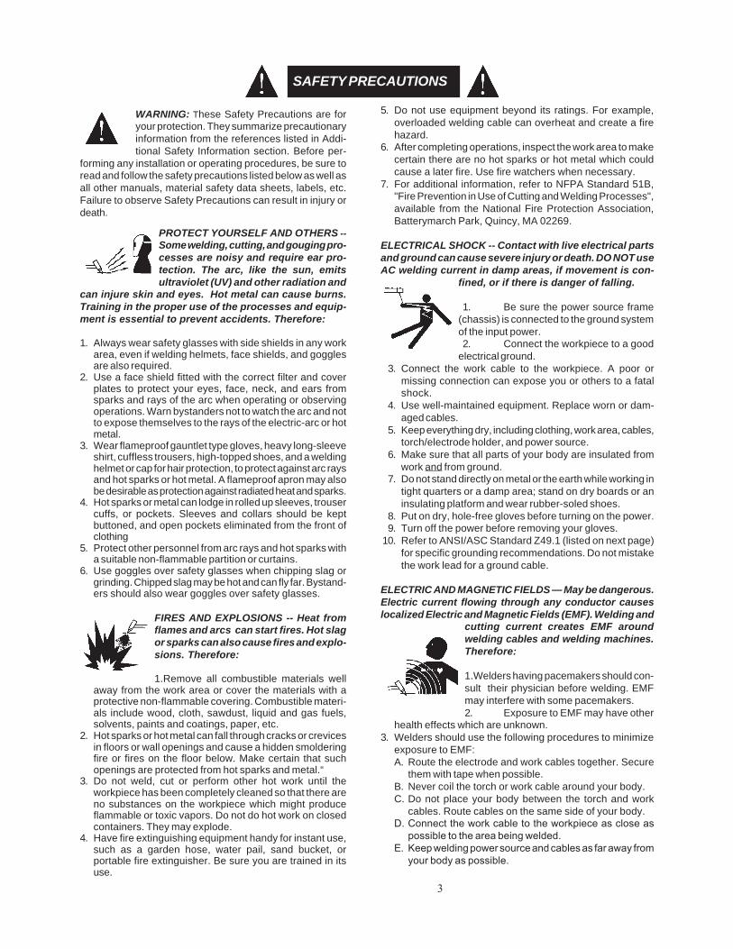
WARNING: These Safety Precautions are foryour protection. They summarize precautionaryinformation from the references listed in Addi-tional Safety Information section. Before per-
forming any installation or operating procedures, be sure toread and follow the safety precautions listed below as well asall other manuals, material safety data sheets, labels, etc.Failure to observe Safety Precautions can result in injury ordeath.
PROTECT YOURSELF AND OTHERS --Some welding, cutting, and gouging pro-cesses are noisy and require ear pro-tection. The arc, like the sun, emitsultraviolet (UV) and other radiation and
can injure skin and eyes. Hot metal can cause burns.Training in the proper use of the processes and equip-ment is essential to prevent accidents. Therefore:
1. Always wear safety glasses with side shields in any workarea, even if welding helmets, face shields, and gogglesare also required.
2. Use a face shield fitted with the correct filter and coverplates to protect your eyes, face, neck, and ears fromsparks and rays of the arc when operating or observingoperations. Warn bystanders not to watch the arc and notto expose themselves to the rays of the electric-arc or hotmetal.
3. Wear flameproof gauntlet type gloves, heavy long-sleeveshirt, cuffless trousers, high-topped shoes, and a weldinghelmet or cap for hair protection, to protect against arc raysand hot sparks or hot metal. A flameproof apron may alsobe desirable as protection against radiated heat and sparks.
4. Hot sparks or metal can lodge in rolled up sleeves, trousercuffs, or pockets. Sleeves and collars should be keptbuttoned, and open pockets eliminated from the front ofclothing
5. Protect other personnel from arc rays and hot sparks witha suitable non-flammable partition or curtains.
6. Use goggles over safety glasses when chipping slag orgrinding. Chipped slag may be hot and can fly far. Bystand-ers should also wear goggles over safety glasses.
FIRES AND EXPLOSIONS -- Heat fromflames and arcs can start fires. Hot slagor sparks can also cause fires and explo-sions. Therefore:
1.Remove all combustible materials wellaway from the work area or cover the materials with aprotective non-flammable covering. Combustible materi-als include wood, cloth, sawdust, liquid and gas fuels,solvents, paints and coatings, paper, etc.
2. Hot sparks or hot metal can fall through cracks or crevicesin floors or wall openings and cause a hidden smolderingfire or fires on the floor below. Make certain that suchopenings are protected from hot sparks and metal.“
3. Do not weld, cut or perform other hot work until theworkpiece has been completely cleaned so that there areno substances on the workpiece which might produceflammable or toxic vapors. Do not do hot work on closedcontainers. They may explode.
4. Have fire extinguishing equipment handy for instant use,such as a garden hose, water pail, sand bucket, orportable fire extinguisher. Be sure you are trained in itsuse.
SAFETY PRECAUTIONS
5. Do not use equipment beyond its ratings. For example,overloaded welding cable can overheat and create a firehazard.
6. After completing operations, inspect the work area to makecertain there are no hot sparks or hot metal which couldcause a later fire. Use fire watchers when necessary.
7. For additional information, refer to NFPA Standard 51B,"Fire Prevention in Use of Cutting and Welding Processes",available from the National Fire Protection Association,Batterymarch Park, Quincy, MA 02269.
ELECTRICAL SHOCK -- Contact with live electrical partsand ground can cause severe injury or death. DO NOT useAC welding current in damp areas, if movement is con-
fined, or if there is danger of falling.
1. Be sure the power source frame(chassis) is connected to the ground systemof the input power.2. Connect the workpiece to a good
electrical ground.3. Connect the work cable to the workpiece. A poor or
missing connection can expose you or others to a fatalshock.
4. Use well-maintained equipment. Replace worn or dam-aged cables.
5. Keep everything dry, including clothing, work area, cables,torch/electrode holder, and power source.
6. Make sure that all parts of your body are insulated fromwork and from ground.
7. Do not stand directly on metal or the earth while working intight quarters or a damp area; stand on dry boards or aninsulating platform and wear rubber-soled shoes.
8. Put on dry, hole-free gloves before turning on the power.9. Turn off the power before removing your gloves.
10. Refer to ANSI/ASC Standard Z49.1 (listed on next page)for specific grounding recommendations. Do not mistakethe work lead for a ground cable.
ELECTRIC AND MAGNETIC FIELDS — May be dangerous.Electric current flowing through any conductor causeslocalized Electric and Magnetic Fields (EMF). Welding and
cutting current creates EMF aroundwelding cables and welding machines.Therefore:
1.Welders having pacemakers should con-sult their physician before welding. EMFmay interfere with some pacemakers.2. Exposure to EMF may have other
health effects which are unknown.3. Welders should use the following procedures to minimize
exposure to EMF:A. Route the electrode and work cables together. Secure
them with tape when possible.B. Never coil the torch or work cable around your body.C. Do not place your body between the torch and work
cables. Route cables on the same side of your body.D. Connect the work cable to the workpiece as close as
possible to the area being welded.E. Keep welding power source and cables as far away from
your body as possible.

4
FUMES AND GASES -- Fumes andgases, can cause discomfort or harm,particularly in confined spaces. Donot breathe fumes and gases. Shield-ing gases can cause asphyxiation.Therefore:
1. Always provide adequate ventilation in the work area bynatural or mechanical means. Do not weld, cut, or gougeon materials such as galvanized steel, stainless steel,copper, zinc, lead, beryllium, or cadmium unless positivemechanical ventilation is provided. Do not breathe fumesfrom these materials.
2. Do not operate near degreasing and spraying operations.The heat or arc rays can react with chlorinated hydrocar-bon vapors to form phosgene, a highly toxic gas, and otherirritant gases.
3. If you develop momentary eye, nose, or throat irritationwhile operating, this is an indication that ventilation is notadequate. Stop work and take necessary steps to improveventilation in the work area. Do not continue to operate ifphysical discomfort persists.
4. Refer to ANSI/ASC Standard Z49.1 (see listing below) forspecific ventilation recommendations.
5. WARNING: This product, when used for welding orcutting, produces fumes or gases whichcontain chemicals known to the State ofCalifornia to cause birth defects and, insome cases, cancer. (California Health &Safety Code §25249.5 et seq.)
CYLINDER HANDLING -- Cylinders, ifmishandled, can rupture and violentlyrelease gas. Sudden rupture of cylin-der, valve, or relief device can injure orkill. Therefore:
1. Use the proper gas for the process and use the properpressure reducing regulator designed to operate from thecompressed gas cylinder. Do not use adaptors. Maintainhoses and fittings in good condition. Follow manufacturer'soperating instructions for mounting regulator to a com-pressed gas cylinder.
2. Always secure cylinders in an upright position by chain orstrap to suitable hand trucks, undercarriages, benches,walls, post, or racks. Never secure cylinders to worktables or fixtures where they may become part of anelectrical circuit.
3. When not in use, keep cylinder valves closed. Have valveprotection cap in place if regulator is not connected.Secure and move cylinders by using suitable hand trucks.Avoid rough handling of cylinders.
4. Locate cylinders away from heat, sparks, and flames.Never strike an arc on a cylinder.
5. For additional information, refer to CGA Standard P-1,"Precautions for Safe Handling of Compressed Gases inCylinders", which is available from Compressed GasAssociation, 1235 Jefferson Davis Highway, Arlington,VA 22202.
EQUIPMENT MAINTENANCE -- Faulty orimproperly maintained equipment cancause injury or death. Therefore:
1. Always have qualified personnel perform the installation,troubleshooting, and maintenance work. Do not performany electrical work unless you are qualified to performsuch work.
2. Before performing any maintenance work inside a powersource, disconnect the power source from the incomingelectrical power.
3. Maintain cables, grounding wire, connections, power cord,and power supply in safe working order. Do not operateany equipment in faulty condition.
4. Do not abuse any equipment or accessories. Keepequipment away from heat sources such as furnaces, wetconditions such as water puddles, oil or grease, corrosiveatmospheres and inclement weather.
5. Keep all safety devices and cabinet covers in position andin good repair.
6. Use equipment only for its intended purpose. Do notmodify it in any manner.
ADDITIONAL SAFETY INFORMATION -- Formore information on safe practices for electricarc welding and cutting equipment, ask yoursupplier for a copy of "Precautions and SafePractices for Arc Welding, Cutting and Goug-ing", Form 52-529.
The following publications, which are available from theAmerican Welding Society, 550 N.W. LeJuene Road, Miami,FL 33126, are recommended to you:1. ANSI/ASC Z49.1 - "Safety in Welding and Cutting"2. AWS C5.1 - "Recommended Practices for Plasma Arc
Welding"3. AWS C5.2 - "Recommended Practices for Plasma Arc
Cutting"4. AWS C5.3 - "Recommended Practices for Air Carbon Arc
Gouging and Cutting"5. AWS C5.5 - "Recommended Practices for Gas Tungsten
Arc Welding“6. AWS C5.6 - "Recommended Practices for Gas Metal Arc
Welding"“7. AWS SP - "Safe Practices" - Reprint, Welding Handbook.8. ANSI/AWS F4.1, "Recommended Safe Practices for Weld-
ing and Cutting of Containers That Have Held HazardousSubstances."
MEANING OF SYMBOLS - As used through-out this manual: Means Attention! Be Alert!Your safety is involved.
Means immediate hazards which, if notavoided, will result in immediate, seri-ous personal injury or loss of life.
Means potential hazards which couldresult in personal injury or loss of life.
Means hazards which could result inminor personal injury.

5
du secteur où l’on exécute des soudures ou des coupesà l’arc, à moins de les recouvrir complètement d’unebâche non-inflammable. Ce type de matériaux comprendnotamment le bois, les vêtements, la sciure, l’essence,le kérosène, les peintures, les solvants, le gaz naturel,l’acétylène, le propane et autres substances combus-tibles semblables.
b. Les étincelles ou les projections de métal incandescentpeuvent tomber dans des fissures du plancher ou dansdes ouvertures des murs et y déclencher une ignitionlente cachée. Veiller à protéger ces ouvertures desétincelles et des projections de métal.
c. N’exécutez pas de soudures, de coupes, d’opérationsde gougeage ou autres travaux à chaud à la surface debarils, bidons, réservoirs ou autres contenants usagés,avant de les avoir nettoyés de toute trace de substancesusceptible de produire des vapeurs inflammables outoxiques.
d. En vue d’assurer la prévention des incendies, il convientde disposer d’un matériel d’extinction prêt à servirimmédiatement, tel qu’un tuyau d’arrosage, un seau àeau, un seau de sable ou un extincteur portatif.
e. Une fois le travail à l’arc terminé, inspectez le secteur defaçon à vous assurer qu’aucune étincelle ou projectionde métal incandescent ne risque de provoquerultérieurement un feu.
3. CHOC ÉLECTRIQUE-- Le gougeage à l’arc et à l’arc auplasma exige l’emploi de tensions à vide relativementimportantes; or, celles-ci risquent de causer desdommages corporels graves et même mortels en casd’utilisation inadéquate. La gravité du choc électriquereçu dépend du chemin suivi par le courant à travers lecorps humain et de son intensité.
a. Ne laissez jamais de surfaces métalliques sous tensionvenir au contact direct de la peau ou de vêtementshumides. Veillez à porter des gants bien secs.
b. Si vous devez effectuer un travail sur une surfacemétallique ou dans un secteur humide, veillez à assu-rervotre isolation corporelle en portant des gants secs etdes chaussures à semelles de caoutchouc et en voustenant sur une planche ou une plate-forme sèche.
c. Mettez toujours à la terre le poste de soudage/coupageen le reliant par un câble à une bonne prise de terre.
d. N’utilisez jamais de câbles usés ou endommagés. Nesurchargez jamais le câble. Utilisez toujours unéquipement correctement entretenu.
e. Mettez l’équipement hors tension lorsqu’il n’est pas enservice. une mise à la masse accidentelle peut en effetprovoquer une surchauffe de l’équipement et un dangerd’incendie. Ne pas enrouler ou passer le câble autourd’une partie quelconque du corps.
f. Vérifiez si le câble de masse est bien relié à la pièce enun point aussi proche que possible de la zone de travail.Le branchement des câbles de masse à l’ossature dubâtiment ou en un point éloigné de la zone de travailaugmente en effet le risque de passage d’un courant desortie par des chaînes de
PRÉCAUTIONS DE SÉCURITÉAVERTISSEMENT: Ces règles de sécurité ont pour objetd’ assurer votre protection. Veillez à lire et à observer lesprécautions énoncées ci-dessous avant de monter l’équipement ou de commercer à l’utiliser. Tout défautd’observation de ces précautions risque d’entraîner desblessures graves ou mortelles.1. PROTECTION INDIVIDUELLE-- Les brûlures de la peau
et des yeux dues au rayonnement de l’arc électrique oudu métal incandescent, lors du soudage au plasma ou àl’électrode ou lors du gougeage à l’arc, peuvent s’avérerplus graves que celles résultant d’une expositionprolongée au soleil. Aussi convient-il d’observer lesprécautions suivantes:
a. Portez un écran facial adéquat muni des plaquesprotectrices et des verres filtrants appropriés afin devous protéger les yeux, le visage, le cou et les oreillesdes étincelles et du rayonnement de l’arc électriquelorsque vous effectuez des soudures ou des coupes oulorsque vous en observez l’exécution.
AVERTISSEZ les personnes se trouvant à proximité defaçon à ce qu’elles ne regardent pas l’arc et à cequ’elles ne s’exposent pas à son rayonnement, ni àcelui du métal incandescent.
b. Portez des gants ignifugés à crispins, une tuniqueépaisse à manches longues, des pantalons sans rebord,des chaussures à embout d’acier et un casque desoudage ou une calotte de protection, afin d’éviterd’exposer la peau au rayonnement de l’arc électriqueou du métal incandescent. ll est également souhaitabled’utiliser un tablier ininflammable de façon à se protégerdes étincelles et du rayonnement thermique.
c. Les étincelles ou les projections de métal incandescentrisquent de se loger dans des manches retroussées,des bords relevés de pantalons ou dans des poches.Aussi convient-il de garder boutonnés le col et lesmanches et de porter des vêtements sans poches àl’avant.
d. Protégez des étincelles et du rayonnement de l’arcélectrique les autres personnes travaillant à proximité àl’aide d’un écran ininflammable adéquat.
e. Ne jamais omettre de porter des lunettes de sécuritélorsque vous vous trouvez dans un secteur où l’oneffectue des opérations de soudage ou de coupage àl’arc. Utilisez des lunettes de sécurité à écrans ouverres latéraux pour piquer ou meûler le laitier. Lespiquetures incandescentes de laitier peuvent êtreprojetées à des distances considérables. Les personnesse trouvant à proximité doivent également porter deslunettes de protection.
f. Le gougeage à l’arc et le soudage à l’arc au plasmaproduisent un niveau de bruit extrêmement élevé (de100 à 114 dB) et exigent par conséquent l’emploi dedispositifs appropriés de protection auditive.
2. PRÉVENTION DES INCENDES-- Les projections delaitier incandescent ou d’étincelles peuvent provoquerde graves incendies au contact de matériaux combus-tibles solides, liquides ou gazeux. Aussi faut-il observerles précautions suivantes:
a. Éloigner suffisamment tous les matériaux combustibles

6
levage, des câbles de grue ou divers cheminsélectriques.
g. Empêchez l’apparition de toute humidité, notammentsur vos vêtements, à la surface de l’emplacement detravail, des câbles, du porte-électrode et du poste desoudage/coupage. Réparez immédiatement toute fuited’eau.
4. VENTILATION-- La respiration prolongée des fuméesrésultant des opérations de soudage/coupage, àl’intérieur, d’un local clos, peut provoquer des malaiseset des dommages corporels. Aussi convient-ild’observer les précautions suivantes:
a. Assurez en permanence une aération adéquate del’emplacement de travail en maintenant une ventilationnaturelle ou à l’aide de moyens mécaniques. N’effectuezjamais de travaux de soudage ou de coupage sur desmatériaux de zinc, de plomb, de beryllium ou de cad-mium en l’absence de moyens mécaniques de ventila-tion capables d’empêcher l’inhalation des fuméesdégagées par ces matériaux.
b. N’effectuez jamais de travaux de soudage ou decoupage à proximité de vapeurs d’hydrocarbure chlorérésultant d’opérations voisines de dégraissage ou depulvérisation. La chaleur dégagée ou le rayonnementde l’arc peut déclencher la formation de phosgène --gaz particulièrement toxique -- et d’autres gaz irritants,à partir des vapeurs de solvant.
c. Une irritation momentanée des yeux, du nez ou de lagorge constatée au cours de l’utilisation de l’équipementdénote un défaut de ventilation. Arrêtez-vous de travaillerafin de prendre les mesures néces- saires àl’amélioration de la ventilation. Ne poursuivez pasl’opération entreprise si le malaise persiste.
d. Certaines commandes comportent des canalisationsoù circule de l’hydrogène. L’armoire de commande estmunie d’un ventilateur destiné à empêcher la formationde poches d’hydrogène, lesquelles présentent un dan-ger d’explosion; ce ventilateur ne fonctionne que sil’interrupteur correspondant du panneau avant se trouveplacé en position ON (Marche). Veillez à manœuvrercette commande en vérifiant si le couvercle est bien enplace, de façon à assurer l’efficacité de la ventilationainsi réalisée. Ne jamais débrancher le ventilateur.
e. Les fumées produites par l’opération de soudage ou decoupage peuvent s’avérer toxiques. Aussi est-ilnécessaire de disposer en permanence d’un dispositifadéquat de ventilation de type aspirant, afin d’élimi-nerdu voisinage de l’opérateur tout dégagement de fuméevisible.
f. Consultez les recommandations particulières en matièrede ventilation indiquées à l’alinéa 6 de la norme Z49.1de l’AWS.
5. ENTRETIEN DE L’ÉQUIPEMENT-- Un équipemententretenu de façon défectueuse ou inadéquate risquenon seulement de réaliser un travail de mauvaisequalité mais, chose plus grave encore, d’entraîner des
dommages corporels graves, voire mortels endéclenchant des incendies ou des chocs électriques.Observez par conséquent les précautions suivantes:
a. Efforcez-vous de toujours confier à un personnel qua-lifiél’installation, le dépannage et l’entretien du poste desoudage et de coupage. N’effectuez aucune réparationélectrique sur l’équipement à moins d’être qua-lifié à ceteffet.
b. Ne procédez jamais à une tâche d’entretien quelconqueà l’intérieur du poste de soudage/coupage, avant d’avoirdébranché l’alimentation électrique.
c. Maintenez en bon état de fonctionnement les câbles, lecâble de masse, les branchements, le cordond’alimentation et le poste de soudage/coupage. N’utilisezjamais le poste ou l’équipement s’il présente unedéfectuosité quelconque.
d. Prenez soin du poste de soudage et de coupage et deséquipements accessoires. Gardez-les à l’écart dessources de charleur, notamment des fours, de l’humidité,des flaques d’eau maintenez-les à l’abri des tracesd’huile ou de graisse, des atmosphères corrosives etdes intempéries.
e. Laissez en place tous les dispositifs de sécurité et tousles panneaux de l’armoire de commande en veillant àles garder en bon état.
f. Utilisez le poste de soudage/coupage conformément àson usage prévu et n’effectuez aucune modification.
6. INFORMATIONS COMPLÉMENTAIRES RELATIVES ÀLA SÉCURITÉ--
Pour obtenir des informations complémentaires sur lesrègles de sécurité à observer pour le montage etl’utilisation d’équipements de soudage et de coupageélectriques et sur les méthodes de travailrecommandées, demandez un exemplaire du livret N°52529 “Precautions and Safe Practices for Arc Weld-ing, Cutting and Gouging” publié par ESAB. Nousconseillons également de consulter les publications sui-vantes, tenues à votre disposition par l’American Weld-ing Society, 550 N.W. LeJuene Road, Miami, FL 32126:
a. “Safety in Welding and Cutting” AWS Z49.1b. “Recommended Safe Practices for Gas-Shielded Arc
Welding “AWS A6. 1.c. “Safe Practices for Welding and Cutting Containers That
Have Held Combustibles” AWS-A6.0.d. “Recommended Safe Practices for Plasma Arc Cutting”
AWS-A6. 3.e. “Recommended Safe Practices for Plasma Arc Weld-
ing” AWS-C5. 1.f. “Recommended Safe Practices for Air Carbon Arc
Gouging and Cutting” AWS-C5. 3.g. “Code For Safety in Welding and Cutting” CSA-Standard
W117. 2.

7
1.1 INTRODUCTION
The Digpulse 450i is a CV/CC inverter-type powersource specifically designed and dedicated for use witha Digipulse wire feeder or Digipulse mechanized/roboticcontrol. When combined, these components work to-gether to provide a pulsed MIG system that self-adjustswhile welding to give optimum arc performance. TheDigipulse system is also designed to provide non-pulseddigital logic needed for convenient MIG short and sprayarc welding applications.
When operated in its Constant Current (CC) setting, thePower Source can be used for a wide range of dc Stick,scratch-start TIG, and air-carbon arc gouging applica-tions.
1.2 SPECIFICATIONS
Rated Output @:....60% Duty .......................... 450 amps @ 38 V dc....100% Duty ......................... 350 amps @ 34 V dcOpen Circuit Voltage (Max.) ......................... 72 V dcInput Voltage ................... 230/460 V ac, 3 ph. 60 HzInput Current @ Rated Load ... 80 amps @ 230 V ac............................................................................................................................... 40 amps @ 460 V ac
Dimensions................. 15.25" (387 mm) w x 23.0" (584 mm) d x...................................................... 15.5" (394 mm)h
Weight .............................................. 166 lbs (70 kg)
Figure 1-1. MIG Mode - VA Curves
Figure 1-2. Duty Cycle Rating Chart
DESCRIPTIONSECTION 1
8
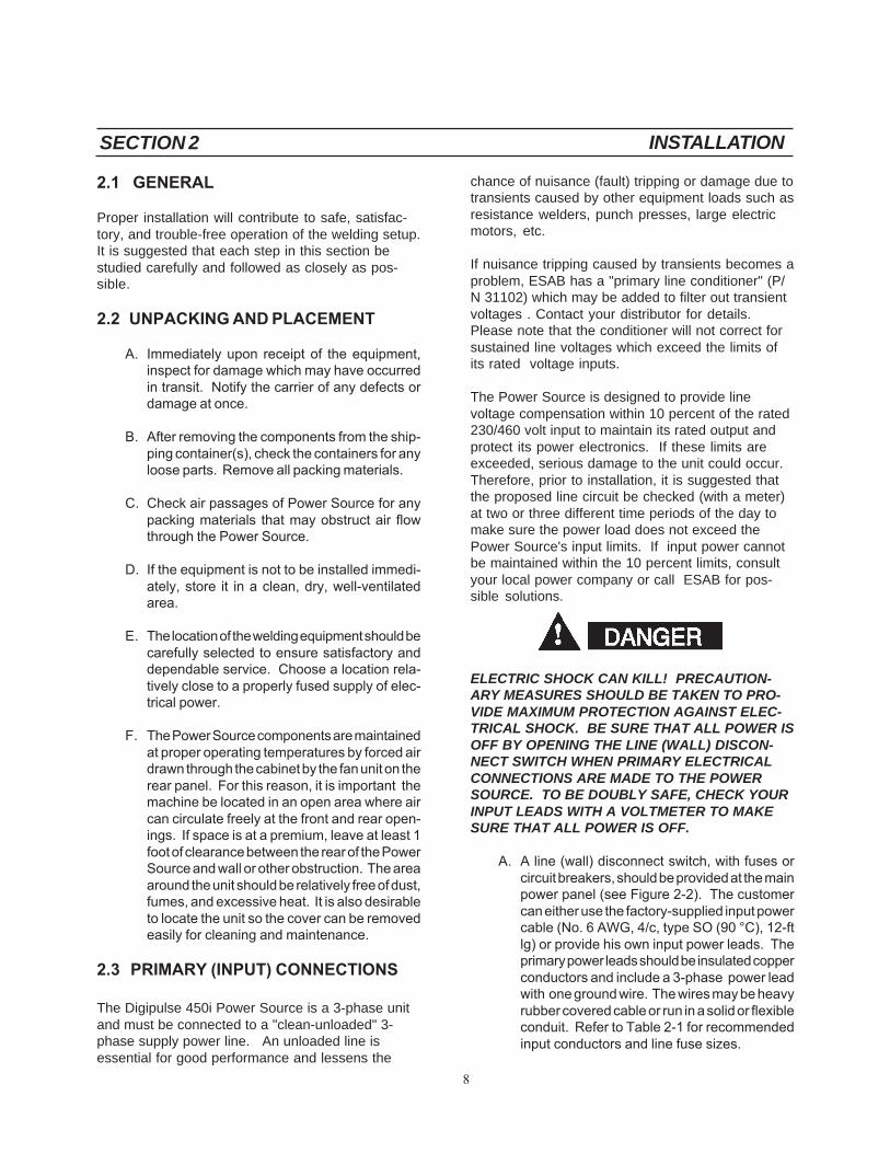
2.1 GENERAL
Proper installation will contribute to safe, satisfac-tory, and trouble-free operation of the welding setup.It is suggested that each step in this section bestudied carefully and followed as closely as pos-sible.
2.2 UNPACKING AND PLACEMENT
A. Immediately upon receipt of the equipment,inspect for damage which may have occurredin transit. Notify the carrier of any defects ordamage at once.
B. After removing the components from the ship-ping container(s), check the containers for anyloose parts. Remove all packing materials.
C. Check air passages of Power Source for anypacking materials that may obstruct air flowthrough the Power Source.
D. If the equipment is not to be installed immedi-ately, store it in a clean, dry, well-ventilatedarea.
E. The location of the welding equipment should becarefully selected to ensure satisfactory anddependable service. Choose a location rela-tively close to a properly fused supply of elec-trical power.
F. The Power Source components are maintainedat proper operating temperatures by forced airdrawn through the cabinet by the fan unit on therear panel. For this reason, it is important themachine be located in an open area where aircan circulate freely at the front and rear open-ings. If space is at a premium, leave at least 1foot of clearance between the rear of the PowerSource and wall or other obstruction. The areaaround the unit should be relatively free of dust,fumes, and excessive heat. It is also desirableto locate the unit so the cover can be removedeasily for cleaning and maintenance.
2.3 PRIMARY (INPUT) CONNECTIONS
The Digipulse 450i Power Source is a 3-phase unitand must be connected to a "clean-unloaded" 3-phase supply power line. An unloaded line isessential for good performance and lessens the
chance of nuisance (fault) tripping or damage due totransients caused by other equipment loads such asresistance welders, punch presses, large electricmotors, etc.
If nuisance tripping caused by transients becomes aproblem, ESAB has a "primary line conditioner" (P/N 31102) which may be added to filter out transientvoltages . Contact your distributor for details.Please note that the conditioner will not correct forsustained line voltages which exceed the limits ofits rated voltage inputs.
The Power Source is designed to provide linevoltage compensation within 10 percent of the rated230/460 volt input to maintain its rated output andprotect its power electronics. If these limits areexceeded, serious damage to the unit could occur.Therefore, prior to installation, it is suggested thatthe proposed line circuit be checked (with a meter)at two or three different time periods of the day tomake sure the power load does not exceed thePower Source's input limits. If input power cannotbe maintained within the 10 percent limits, consultyour local power company or call ESAB for pos-sible solutions.
ELECTRIC SHOCK CAN KILL! PRECAUTION-ARY MEASURES SHOULD BE TAKEN TO PRO-VIDE MAXIMUM PROTECTION AGAINST ELEC-TRICAL SHOCK. BE SURE THAT ALL POWER ISOFF BY OPENING THE LINE (WALL) DISCON-NECT SWITCH WHEN PRIMARY ELECTRICALCONNECTIONS ARE MADE TO THE POWERSOURCE. TO BE DOUBLY SAFE, CHECK YOURINPUT LEADS WITH A VOLTMETER TO MAKESURE THAT ALL POWER IS OFF.
A. A line (wall) disconnect switch, with fuses orcircuit breakers, should be provided at the mainpower panel (see Figure 2-2). The customercan either use the factory-supplied input powercable (No. 6 AWG, 4/c, type SO (90 °C), 12-ftlg) or provide his own input power leads. Theprimary power leads should be insulated copperconductors and include a 3-phase power leadwith one ground wire. The wires may be heavyrubber covered cable or run in a solid or flexibleconduit. Refer to Table 2-1 for recommendedinput conductors and line fuse sizes.
SECTION 2 INSTALLATION

9
Table 2-1. Recommended Sizes forInput Conductors and Line Fuses
Rated Load
Volts Amps
Input &Gnd.Conductor*CU/AWG
Time-DelayFuse SizeAmps
230460
8040
68
10050
*Sizes per National Electric Code for 90°C rated copper conductors@ 30 °C ambient. Not more than three conductors in raceway orcable. Local codes should be followed if they specify sizes otherthan those listed above.
B. As shipped, the Power Source is set up for 460volt input power. If using a 230 volt input, twolinks on the input terminal board (located insidethe unit) must be repositioned as marked on theplate (see Figure 2-1). The input terminal boardconnections will be visible after removing the topcover.
C. The factory-supplied input power cable is con-nected to the Power Source ON-OFF switch.However, if the customer wishes to connect hisown input power leads, proceed as follows:With the top cover and left side panel removed,thread the input conductor cable from the walldisconnect switch through the strain relief holein the rear panel. Connect the primary leads tothe Line Switch (LS) for either single- or 3-phase input and the ground lead (green) to thestud on the base of the unit as shown in Figure2-2. After making sure the connections aresecured, tighten the strain relief coupling tosecure the input cable.
Figure 2-1. Input Voltage Terminal Board(TB) Connections
D. Recheck all connections to make sure they aretight, well insulated, and properly connected.
2.4 SECONDARY (OUTPUT) WELDING CONNECTIONS
BEFORE MAKING ANY CONNECTIONS TO THEPOWER SOURCE OUTPUT TERMINALS, MAKESURE THAT ALL PRIMARY INPUT POWER TOTHE UNIT IS DEENERGIZED (OFF) AT THECUSTOMER'S DISCONNECT SWITCH.
A. Digipulse MIG Setup (see Figure 2-2). ThisPower Source is designed to provide MIGwelding operating characteristics only when theJ2 control receptacle is "vacant" (meaning noaccessories are plugged in) or, if the remoteHC-3B Hand Control (P/N 33838) is plugged in.The Process Switch must be set in the Digital-MIG (center) position for Digipulse controls.Additionally, proper operation of the PowerSource depends on the use of copper outputcables that are insulated, of adequate size, ingood condition, and properly connected to themachine using the jack plug connectors pro-vided with the Power Source. It is recommendedonly 4/0 welding output cable be used regard-less of length and current to be used, and thatthese cables be kept as short as possible (Totallength including work and electrode leads shouldnot exceed 100 feet. Beyond this distance,there will be performance deterioration. Consultwith the factory if you have an application of thisnature.)
Particular attention should be paid to highresistance in the welding circuit; specifically,the work cable/circuit and water-cooled torchcable. It is recommended that the Power
SECTION 2 INSTALLATION
IT IS OF THE UTMOST IMPORTANCE THATTHE CHASSIS BE CONNECTED TO AN AP-PROVED ELECTRICAL GROUND TO PREVENTACCIDENTAL SHOCK. TAKE CARE NOT TOCONNECT THE GROUND WIRE TO ANY OFTHE PRIMARY LEADS.

10
Source/Wire Feeder and workpiece be placedas close together as possible to limit resistancein the welding circuit. High resistance in thewelding circuit can cause performance deterio-ration (loss of "heat" input, popping of weldpuddle, bushy arcs, etc.). Ensure the workcable is large enough (refer to Table 2-2), keptas short as possible, properly insulated, se-curely connected to the workpiece, and that allconnections are clean and tightly secured. If aseparate work circuit is used (such as inmechanical fixturing, shipbuilding, robotfixturing, etc.), make sure the work circuit issecure and presents a low resistance path to theflow of welding current. Also, the power cableon a water-cooled torch is normally subject togradual deterioration and increased resistancedue to corrosion. This leads to poor perfor-mance as described above. To assure goodtorch performance, the water-cooled powercable should be replaced periodically.
The welding output receptacles are located onthe front panel; one negative (-) and one positive(+) receptacle. Two male plug connectors (P/N 950693) are supplied with the Power Sourcefor attachment to customer supplied 4/0 weldingcables (see Figure 2-2). This Power Source isdesigned for conventional and pulsed MIGspray arc applications using Direct CurrentReverse Polarity (DCRP) setup. In a DCRPsetup, the torch or electrode is positive (+), andthe workpiece is negative (-).
B. Stick/Scratch-Start TIG/ Arc Gouging Setup(see Figure 2-3). These processes require
Figure 2-2. MIG Interconnection Diagram
SECTION 2 INSTALLATION
11
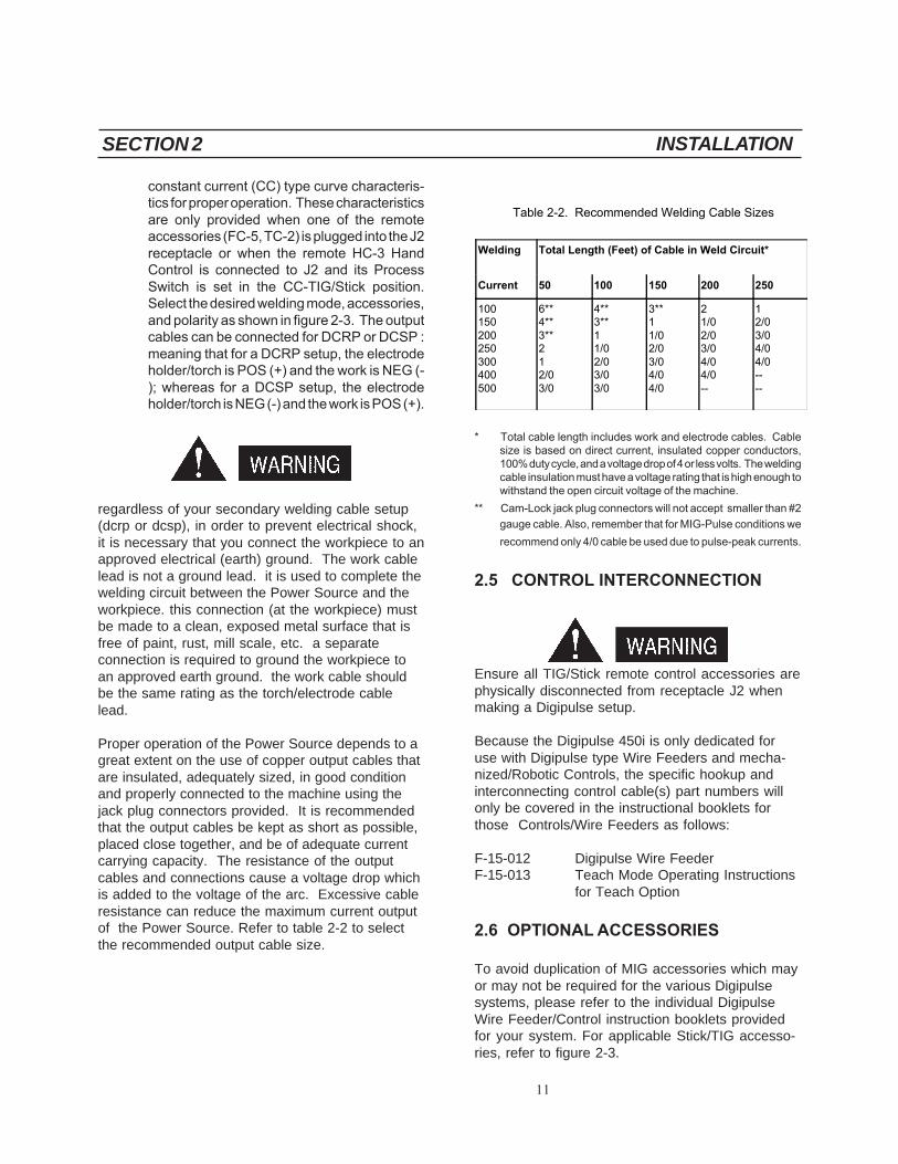
constant current (CC) type curve characteris-tics for proper operation. These characteristicsare only provided when one of the remoteaccessories (FC-5, TC-2) is plugged into the J2receptacle or when the remote HC-3 HandControl is connected to J2 and its ProcessSwitch is set in the CC-TIG/Stick position.Select the desired welding mode, accessories,and polarity as shown in figure 2-3. The outputcables can be connected for DCRP or DCSP :meaning that for a DCRP setup, the electrodeholder/torch is POS (+) and the work is NEG (-); whereas for a DCSP setup, the electrodeholder/torch is NEG (-) and the work is POS (+).
regardless of your secondary welding cable setup(dcrp or dcsp), in order to prevent electrical shock,it is necessary that you connect the workpiece to anapproved electrical (earth) ground. The work cablelead is not a ground lead. it is used to complete thewelding circuit between the Power Source and theworkpiece. this connection (at the workpiece) mustbe made to a clean, exposed metal surface that isfree of paint, rust, mill scale, etc. a separateconnection is required to ground the workpiece toan approved earth ground. the work cable shouldbe the same rating as the torch/electrode cablelead.
Proper operation of the Power Source depends to agreat extent on the use of copper output cables thatare insulated, adequately sized, in good conditionand properly connected to the machine using thejack plug connectors provided. It is recommendedthat the output cables be kept as short as possible,placed close together, and be of adequate currentcarrying capacity. The resistance of the outputcables and connections cause a voltage drop whichis added to the voltage of the arc. Excessive cableresistance can reduce the maximum current outputof the Power Source. Refer to table 2-2 to selectthe recommended output cable size.
Table 2-2. Recommended Welding Cable Sizes
Welding Total Length (Feet) of Cable in Weld Circuit*
Current 50 100 150 200 250
100150200250300400500
6**4**3**212/03/0
4**3**11/02/03/03/0
3**11/02/03/04/04/0
21/02/03/04/04/0--
12/03/04/04/0----
* Total cable length includes work and electrode cables. Cablesize is based on direct current, insulated copper conductors,100% duty cycle, and a voltage drop of 4 or less volts. The weldingcable insulation must have a voltage rating that is high enough towithstand the open circuit voltage of the machine.
** Cam-Lock jack plug connectors will not accept smaller than #2
gauge cable. Also, remember that for MIG-Pulse conditions we
recommend only 4/0 cable be used due to pulse-peak currents.
2.5 CONTROL INTERCONNECTION
Ensure all TIG/Stick remote control accessories arephysically disconnected from receptacle J2 whenmaking a Digipulse setup.
Because the Digipulse 450i is only dedicated foruse with Digipulse type Wire Feeders and mecha-nized/Robotic Controls, the specific hookup andinterconnecting control cable(s) part numbers willonly be covered in the instructional booklets forthose Controls/Wire Feeders as follows:
F-15-012 Digipulse Wire FeederF-15-013 Teach Mode Operating Instructions
for Teach Option
2.6 OPTIONAL ACCESSORIES
To avoid duplication of MIG accessories which mayor may not be required for the various Digipulsesystems, please refer to the individual DigipulseWire Feeder/Control instruction booklets providedfor your system. For applicable Stick/TIG accesso-ries, refer to figure 2-3.
SECTION 2 INSTALLATION

12
Figure 2-3. Stick/Scratch-Start TIG/Arc Gouging Interconnection Diagram
SECTION 2 INSTALLATION

13
SECTION 3 OPERATION
C. Troubleshooting Lights.
1. Temperature (PL2). This will light ifcomponents in the Power Sourceoverheat. The contactor will thendeenergize. Allow the Power Source tocool with the line switch in the "ON"position (the fan will help cool thePower Source) before continuingwelding operations when light goes off.
2. Fault (PL3). This light functions as avisual detector for two specific faultconditions: overcurrent or over/undervoltage indication. In either case,if a fault is detected in the inverterbridge, the contactor will deenergizeand the Power Source will stop welding.If an overcurrent condition caused theproblem, the fault light will energize andremain "steady-on." Do not attempt torestart welding (refer to section 5). Ifan over or undervoltage conditionoccurs, the fault light will flash. Sincethis can often be caused by a transient,retry the torch switch to resume weld-ing. If tripping continues, stop and referto section 5.
D. Inductance Control Potentiometer (ICP).This control allows the operator to set andregulate the desired amount of inductancerequired for standard MIG short arc weldingoperations. Variable control allows the operatorto fine tune the inductance needed to make theweld puddle more fluid and minimize the weldspatter produced during MIG short arc applica-tions. When short arc welding stainless steel,high values of inductance should be used withA1025 helium rich shielding gas. This potenti-ometer should be set to minimum for all pulseand standard spray arc welding applications.
E. Digital MIG Control Receptacle (J1). This 19-pin remote control receptacle receives a matingconnector from the Digipulse Wire Feeder orother Digipulse Controls (see Figure 2-2).
F. TIG/Stick Control Receptacle (J2). This 8-pinremote control receptacle, located on the rearpanel, receives a mating connector from theTIG/Stick accessories (see Figure 2-3).
3.1 INTRODUCTION
This section is intended to familiarize personnelwith the operational procedures applicable to theDigipulse 450i Power Source. Information containedin this section should be read carefully beforeoperation of the Power Source.
NEVER, UNDER ANY CIRCUMSTANCES, OPER-ATE THE POWER SOURCE WITH THE COVEROR SIDE PANELS REMOVED. IN ADDITION TOTHE SAFETY HAZARD, IMPROPER COOLINGMAY CAUSE DAMAGE TO INTERNAL COMPO-NENTS. ALSO MAKE SURE YOU ARE AD-EQUATELY PROTECTED BEFORE WELDING.WELDING HELMET, GLOVES, SAFETY GLASSES,AND EAR PROTECTION SHOULD ALWAYS BEWORN.
3.2 DUTY CYCLE
Duty cycle is defined as the ratio of load time tototal time. Standard current ratings are based on a10-minute cycle. The Digipulse 450i Power Sourcehas two duty cycles; a 60% duty cycle rating whichallows 450i amperes @ 38 V dc, and a 100% dutycycle rating which allows 350 amperes @ 34 V dc(see Figure 2-2). The 100% duty cycle means that a350 ampere rated load can be applied continuouslywith no adverse effect on the Power Source. The60% duty cycle rating means that the 450i ampererated load can be applied for a total of 6 minutesand shut off for a total 4 minutes in a 10-minuteperiod. If the welding current is decreased, the dutycycle can be increased. Conversely, if the weldingcurrent is increased, the duty cycle must be de-creased.
3.3 POWER SOURCE WELDING CONTROLS
A. On-Off Line Switch (LS). Placed in the "on"position, this switch (located on the rear panel)provides primary input power to start the coolingfan motor and energize the secondary controlcircuitry. Power light (PL1) on the front panelshould illuminate.
B. Digital Ammeter. This instrument providesdirect reading of the average welding current.

14
G. Reset Circuit Breaker (CB). A 10 amperecircuit breaker (on the rear panel) providesprotection to the 115 volt control circuit. If anoverload occurs, the breaker will trip and sus-pend all operation. To restore service, depressthe breaker button to reset the circuit.
H. Auxiliary 115 Volt Receptacle (J3). This re-ceptacle supplies 5 amperes of 115 V/5 A powerfor auxiliary equipment.
I. Welding Output Receptacles. Two outputreceptacles are located on the front panel - onenegative (-) and one positive (+) (see Figure 2-2 and 2-3).
3.4 SEQUENCE OF OPERATION
never, under any circumstances, operate the PowerSource without cover or panels in place. in additionto the safety hazard, improper cooling may causeoverheating which will damage the internal compo-nents. also, make sure you are adequately pro-tected before welding. welding helmet, gloves,safety glasses, and ear protection should always beworn.
A. Digipulse MIG Welding
1. Make all secondary output connections to thePower Source output receptacles as describedin section 2 (see Figure 2-2) and as shown inthe appropriate Wire Feeder and/or Controlinstruction booklets.
2. Make the necessary control connections toreceptacle J1 as described in section 2 (seeFigure 2-2) and J2, if necessary. Make sure thatFC-5B or TC-2B is unplugged from J2, or if HC-3B is plugged in, the Process Switch is in theDigital-MIG (center) position.
3. After the primary input connections have beenmade in accordance with section 2, close themain wall disconnect switch or circuit breaker.
4. Place the Power Source ON-OFF line switch(on rear panel) to the ON position. This will startthe cooling fan and apply power to the controlcircuitry as indicated by the illuminated POWERpilot light on the front panel.
5. Set the variable inductance control (on the frontpanel) to provide the amount of inductancedesired for MIG short arc welding. For MIGspray arc and pulsed MIG welding, thiscontrol should be set at MINIMUM.
6. For remaining Digipulse Wire Feeder orDigipulse Control operations, refer to the appro-priate instruction booklet supplied for yourparticular system.
B. Stick/Scratch-Start TIG Welding
1. Depending on the process being used, make allsecondary output connections to the PowerSource output receptacles (refer to Figure 2-3).
2. Connect appropriate control accessories toreceptacle J2 (refer to Figure 2-3).
3. After the primary input connections have beenmade, close the main wall disconnect switchor circuit breaker.
4. Place the Power Source ON-OFF line switch(on the rear panel) to the ON position. This willstart the cooling fan and apply power to thecontrol circuitry as indicated by the illuminatedPOWER pilot light on the front panel.
Ensure the contactor control switch on the TC-2B torchcontrol or the Stick control pendant is in its OFFposition (until you're ready to weld); otherwise, theelectrode will be energized and may cause a short orelectrical shock.
5. The variable inductance control need not be setfor these processes because it is isolated fromthis circuit.
6. Full range current control is provided and regu-lated by the potentiometer on the selectedremote controls.
7. To establish the welding arc, position the torch/electrode near the workpiece. Close the remotetorch/foot control or turn ON the pendant. Thiswill energize the solid-state contactor and pro-
SECTION 3 OPERATION
15
SECTION 4 MAINTENANCE
4.1 GENERAL
If the Power Source does not operate properly, stopwork immediately and investigate the cause of themalfunction. Maintenance work must be performedby an experienced person, and electrical work by atrained electrician. Do not permit untrained personsto inspect, clean, or repair this equipment. Useonly recommended replacement parts.
ENSURE THE WALL DISCONNECT SWITCH ORCIRCUIT BREAKER IS OPEN BEFORE AT-TEMPTING ANY INSPECTION OR WORK ON THEINSIDE OF THE POWER SOURCE. ALWAYSWEAR SAFETY GOGGLES WITH SIDE SHIELDSWHEN BLOWING OUT THE POWER SOURCEWITH THE LOW PRESSURE AIR.
4.2 CLEANING
Since there are no moving parts (other than the fan)in the Power Source, maintenance consists mainlyof keeping the interior of the cabinet clean. Peri-odically, remove the cover from the cabinet and,wearing proper eye protection, blow accumulateddust and dirt from the air passages and the interiorcomponents using clean low pressure air. It isimperative that the air passages to the interior ofthe unit be kept free of dirt accumulation to ensureadequate circulation of cooling air; especially, overthe rectifier bridge plates. The length of timebetween cleaning will depend on the location of theunit and the amount of dust in the atmosphere.
4.3 LUBRICATION
Fan motors with oil tubes located on the side of themotor require lubrication after 1 year of service.Motors without oil tubes are permanently lubricatedfor life and should not require any attention.

16
SECTION 5 TROUBLESHOOTING
5. Apply input power to the Power Source, and performthe low voltage checks described in the followingtables.
6. After the low voltage checks are completed, discon-nect input power to Power Source and reconnect IBR(+) and (-) leads to module, and reinstall the unit's sidepanels.
7. With the side panels in place, reapply input power tothe Power Source and perform high voltage checks
(designated by )listed in the following tables.
A. Digipulse Wire Feeder or Control
If it is determined that the Wire Feeder is operatingimproperly, refer to the troubleshooting informationlocated in booklet F-15-012.
B. Digipulse Power Source
If the Power Source is operating improperly, thefollowing troubleshooting information may be usedto locate the source of the problem.
Check the problem using the following troubleshoot-ing guide. The potential problems are listed in"most probable" order, and the remedy may be quitesimple. If the cause cannot be located quickly,open up the unit and perform a simple visualinspection of all components and wiring. Check forsecure terminal and plug connections, loose orburned wiring or components, bulged or leakingcapacitors, or any other sign of damage or discol-oration. Always follow this general rule -- Do notreplace a printed circuit (PC) board until you havemade all of the checks listed in the following guide.Always put the power switch in its OFF positionbefore removing or installing a PC board. Takegreat care not to grasp or pull on components whenremoving a PC board and always place a removedboard on a static-free surface. If a PC board isdetermined to be the problem, check with yourESAB supplier for a replacement. Provide thedistributor with the part number of the board, as wellas the serial number of the Power Source. Do notattempt to repair the board yourself. Warrantyon a PC board will be null and void if repaired by
H.V.
5.1 Troubleshooting
ENSURE ALL PRIMARY POWER TO THE POWERSOURCE HAS BEEN EXTERNALLY DISCON-NECTED. OPEN WALL DISCONNECT SWITCHOR CIRCUIT BREAKER BEFORE ATTEMPTINGINSPECTION OF WORK INSIDE OF THE POWERSOURCE.
CAPACITORS CAN EXPLODE CAUSING PER-SONAL INJURY. TO AVOID INJURY, CAREFULLYREAD AND DO THE FOLLOWING:
THE SUBJECT WARNING CONCERNS THE FOURPOWER FILTERING CAPACITORS MOUNTEDBEHIND POWER BOARD #1 AND #2 (FOR LOCA-TION, SEE FIGURE 6-3).
This potential hazard exists when the side panels are removedand power is ON. This should only occur when troubleshoot-ing the Power Source.
Safe troubleshooting practice requires a systematic procedureas follows:
1. Disconnect primary input power to Power Source.
2. Remove panels and perform visual inspection forobvious problems; loose wiring and plug connections,damaged or discolored components, etc.
3. Perform resistance checks described in the followingtables.
4. With input power deenergized and side panels re-moved, locate the Input Bridge Module (IBR) (seeFigures 5-1 and 6-5). Using the existing wiring dia-gram (Figure 5-4), disconnect and tape the large grayleads attached to terminals IBR (+) and IBR (-). Thiswill prevent high voltage input to power boards #1 and#2, eliminating the potential hazard while performingthe low voltage checks in step 5.
NOTE
High voltage checks, listed in the following tables, must beperformed with the side panels installed and IBR leadsconnected. To distinguish the high voltage checks (from lowvoltage) we have indicated these readings with the followingsymbol H.V.

17
TROUBLESHOOTING GUIDE
PROBLEM POSSIBLE CAUSE CIRCUIT CHECKS
Unit inoperative - fandoes not run
Single-phase operation
Incorrect linkages on voltage changeoverboard
Defective Line Switch (LS)
Check incoming power to unit - all threephases
Check links on voltage changeoverterminal board
Perform continuity check on Line Switch
Blows input line fuses Defective Input Bridge (IBR)
Incorrect linkages on voltage changeoverboard
Defective PB1/PB2
See IBR Troubleshooting
Check links on voltage changeoverterminal board
See PB1/PB2 Troubleshooting
No open circuitvoltage
115 V ac circuit breaker tripped
MIG mode operation 1. Stick pendant/control plugged intoJ2
2. No contactor signal from wire feeder/control
STICK mode operation 1. No contactor signal from pendant/control
Check circuit breaker and reset if tripped
Check J2 and disconnect pendant/footcontrol
Check MIG contactor signal - seeInverter Control Board troubleshooting
Check STICK contactor signal - seeinverter control troubleshooting
No open circuitvoltage
Defective SCR1/R1
Missing bias voltage to Inverter ControlBoard (ICB)
False thermal indication to ICB
Defective ICB
See SCR1 troubleshooting
See ICB troubleshooting
See ICB troubleshooting
Replace ICB
Excessive open circuitvoltage
Defective resistor/capacitor across OutputBridge (OBR)
Check components R4, C7, R5, C8
Thermal overload Exceeding duty cycle rating
Exceeding max rated ambienttemperature
See duty cycle rating chart
40 °C (104 °F)
SECTION 5 TROUBLESHOOTING

18
TROUBLESHOOTING GUIDE - Continued
PROBLEM POSSIBLE CAUSE CIRCUIT CHECKS
Flashing fault indicator Input voltage not within +15% and -10% ofrated requirements
Excessive line impedance
Defective Inverter Control Board (ICB)
Check incoming voltage to unit - all threephases
Check voltage TB-1 (+) to TB-4(-). SeeIBR troubleshooting
Replace ICB
Continuous faultindicator
Defective PB1/PB2
Defective Output Bridge Module (OBR1-4)
CT1/CT2 lead open
Missing shunt signal to Inverter ControlBoard (ICB)
Defective ICB
See PB1/PB2 troubleshooting
See OBR troubleshooting
Disconnect P4 connector to invertercontrol and make continuity check P4-1to P4-2/P4-4 to P4-5
See ICB troubleshooting
Replace ICB
Low welding output Single-phase operation
Excessive welding cable length
Too small a size welding cable beingused
High resistance torch power cable
Inverter Control Board (ICB) calibration
Defective ICB
Check incoming power to unit - all threephases
Recommend max cable length (work andtorch) of 100 ft.
Recommend 4/0 cable for Migapplications
Replace torch if defective/use torch withvoltage pickup lead
See ICB troubleshooting
Replace ICB
Excessive weldingoutput
Missing arc voltage feedback to InverterControl Board (ICB)
ICB calibration
Defective ICB
See ICB troubleshooting
See ICB troubleshooting
See ICB troubleshooting
SECTION 5 TROUBLESHOOTING
19
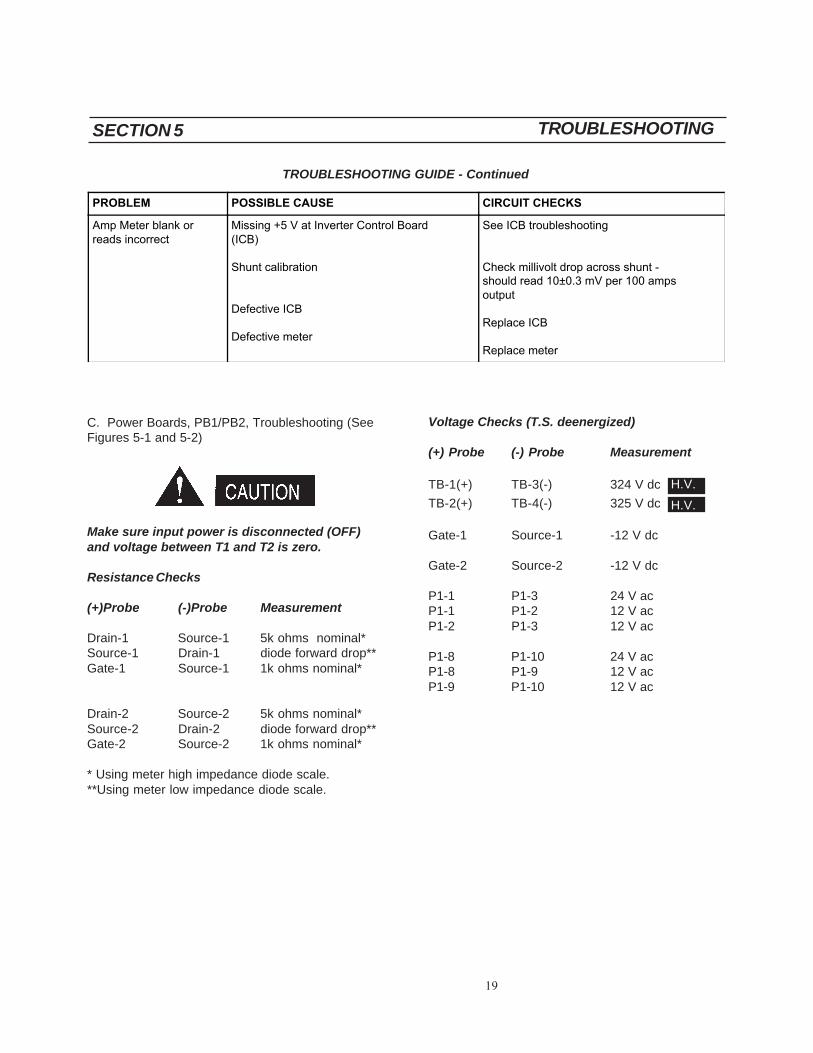
C. Power Boards, PB1/PB2, Troubleshooting (SeeFigures 5-1 and 5-2)
Make sure input power is disconnected (OFF)and voltage between T1 and T2 is zero.
Resistance Checks
(+)Probe (-)Probe Measurement
Drain-1 Source-1 5k ohms nominal*Source-1 Drain-1 diode forward drop**Gate-1 Source-1 1k ohms nominal*
Drain-2 Source-2 5k ohms nominal*Source-2 Drain-2 diode forward drop**Gate-2 Source-2 1k ohms nominal*
* Using meter high impedance diode scale.**Using meter low impedance diode scale.
Voltage Checks (T.S. deenergized)
(+) Probe (-) Probe Measurement
TB-1(+) TB-3(-) 324 V dc
TB-2(+) TB-4(-) 325 V dc
Gate-1 Source-1 -12 V dc
Gate-2 Source-2 -12 V dc
P1-1 P1-3 24 V acP1-1 P1-2 12 V acP1-2 P1-3 12 V ac
P1-8 P1-10 24 V acP1-8 P1-9 12 V acP1-9 P1-10 12 V ac
H.V.
H.V.
TROUBLESHOOTING GUIDE - Continued
PROBLEM POSSIBLE CAUSE CIRCUIT CHECKS
Amp Meter blank orreads incorrect
Missing +5 V at Inverter Control Board(ICB)
Shunt calibration
Defective ICB
Defective meter
See ICB troubleshooting
Check millivolt drop across shunt -should read 10±0.3 mV per 100 ampsoutput
Replace ICB
Replace meter
SECTION 5 TROUBLESHOOTING

20
D. Input Bridge, IBR, Troubleshooting (See Figure5-1)
Resistance Checks
(+) Probe (-) Probe Measurement
IBR-1,2,3 IBR (+) diode forwarddrop**IBR (+) IBR-1,2,3 open*
IBR (-) IBR-1,2,3 diode forwarddrop**IBR-1,2,3 IBR (-) open *
*Using meter high impedance diode scale.**Using meter low impedance diode scale.
TB-1(+) 375-290 V dc @ 230 V ac(+15%/-10%)
TB-4(-) 750-580 V dc @ 460 V ac(+15%/-10%)
E. Output Bridge, OBR, Troubleshooting (SeeFigure 5-2)
Resistance Checks
Anode-1 Cathode diode forwarddrop**Anode-2 Cathode diode forwarddrop**
Cathode Anode-1 open*Cathode Anode-2 open*
*Using meter high impedance diode scale.**Using meter low impedance diode scale.
NOTE
If any of the above readings are incorrect, removethe bus bars and check modules OBR1-4 individu-ally. Replace modules which are defective.
F. SCR1 Troubleshooting (See Figure 5-1)
Resistance Checks
SCR1-A SCR1-K 5 ohms If reads open, then replace R1
SCR1-G SCR1-K diode forward drop (low impedance using diode scale)
If reads short, then replace SCR-1
Voltage Checks
SCR1-G SCR1-K 0 V dc Torch switch deenergized
0.6 V dc Torch switch energized - if missing, check InverterControl
H.V.
H.V.
SECTION 5 TROUBLESHOOTING

21
T1, T2, POWER CABLE CONNECTIONS *
CAPACITOR MOUNTING BRACKETS (BEHIND BOARD) *P1, CONTROL PLUG *
P.C. BOARD MOUNTINGSCREW, TYPICAL EACH SIDE *
ISOBAR, TYPICAL EACH SIDE *
T3, T4, POWER CABLE CONNECTIONS *
Torque Specifications
IBR ¶Case to Heatsink - 40 lb in.Terminals - 25 lb. in.
SCR1¶Case to Heatsink - 25 lb. in.Terminals -25 lb. in.
PA1 - Transistors¶
Case to Isobar - 10 lb.in.
When replacing thecomponents, makesure mountingsurfaces are clean.Coat surfaces withDow-Corning #340silicon heat sinkcompound orequivalent. Allhardware must betorqued to abovespecifications.
*To replace Power Boards (PB-1 & PB-2), Disconnect cables from T1-T4, Disconnectcontrol plug P1, loosen capacitor mounting brackets behind board, remove and retaintransistor mounting screws and two mounting screws at bottom of board. NEVER,UNDER ANY CIRCUMSTANCES, REMOVE OR LOOSEN ISOBARS ATTACHED TO HEATSINK!
(TYP.) TRANSISTOR MOUNTING * SCREW (TOTAL-16)
Figure 5-1. Left Side Power/Control Components (PB-1, SCR1, IBR, R1)
*To replace Power Boards (PB-1 & PB-2), Disconnect cables from T1-T4, Disconnectcontrol plug P1, loosen capacitor mounting brackets behind board, remove and retaintransistor mounting screws and two mounting screws at bottom of board. NEVER,UNDER ANY CIRCUMSTANCES, REMOVE OR LOOSEN ISOBARS ATTACHED TO HEATSINK!
CAPACITOR MOUNTING BRACKETS (BEHIND BOARD) *
P1, CONTROL PLUG *
T1, T2, POWER CABLE CONNECTIONS *
(TYP.) TRANSISTOR MOUNTING * SCREW (TOTAL-16)
T3, T4, POWER CABLE CONNECTIONS *
P.C. BOARD MOUNTING SCREW, TYPICAL EACH SIDE *
ISOBAR, TYPICAL EACH SIDE *
Torque Specifications
IBR ¶Case to Heatsink - 40 lb in.Terminals - 25 lb. in.
PA2 - Transistors¶
Case to Isobar - 10 lb.in.
When replacing thecomponents, makesure mountingsurfaces are clean.Coat surfaces withDow-Corning #340silicon heat sinkcompound orequivalent. Allhardware must betorqued to abovespecifications.
Figure 5-2. Right Side Power/Control Components (PB-2, OBR-1,2,3,4)
SECTION 5 TROUBLESHOOTING

22
G. Inverter Control Board, ICB, Troubleshooting (See Figure 5-3)
Voltage Checks
(+) Probe (-) Probe Measurements
P5-8 P5-9 18 V ac AC BiasP5-8 P5-10 36 V ac AC Bias
P5-6 P2-9 12 V dc DC BiasP5-5 P2-9 -12 V dc DC BiasP5-3 P1-6 5 V dc Digital Meter BiasP5-1 P2-9 10 V dc DC Bias
P4-7 P4-8 115 V ac MIG Contactor SignalP4-9 P4-10 24 V ac Stick Contactor Signal
P2-10 P3-1 72 V dc Arc Voltage - open circuit
P1-1 P1-2 10 ±0.3 mV Shunt Signal/100 ampsP1-4 P1-5 10 ±0.3 mV Meter Signal/100 amps
P2-4 P2-3 1.3 to 0 V dc Inductance Control (Min to Max)
P3-3 P2-2 12 V dc MIG Mode Select 0 V dc Stick Mode Select
P3-2 P2-9 12 V dc Pulsed MIG Select 0 V dc STD MIG Select
P3-9 P3-10 0 V dc Thermal-Normal12 V dc Thermal-Overload
5.2 CALIBRATION PROCEDURE
The following calibration should be performed after confirming the above voltage checks. Use a calibratedexternal means of measuring output voltage and current.
The Wire Feeder should be set to schedule zero and in the Synergic/Spray Arc mode (Digipulse 450i WireFeeder control always operates in the Synergic mode.)
To set the Wire Feeder control to schedule zero, depress the WIRE DIA./MATL. key and simultaneously holddown the IPM DEC key position for 2.5 seconds until a zero appears in the IPM window. Release both switchkeys and set the following data in the IPM and VOLTS window as described below.
Connect voltmeter between TP1 and P2-9. With torch deenergized, adjust theoffset voltage to read 0±10 mV bymeans of R44.
H.V.
SECTION 5 TROUBLESHOOTING

23
Figure 5-3. Inverter Control Board (ICB) (Top View Layout)
P2-8 P2-9 3 V dc If these voltages are unavailable, refer to the WireP1-10 P2-9 0 V dc Feeder booklet for troubleshooting procedures.Output Current 400±5 amps Current can be trimmed by means of R3.
Set 3.0 in the VOLTS window and 0 in the IPM window. Short circuit the contact tip to the work piece andenergize the torch switch.
TP1
TP2
SECTION 5 TROUBLESHOOTING
P2-8 P2-9 0 V dc If these voltages are unavailable, refer to the WireP1-10 P2-9 2 V dc Feeder booklet for troubleshooting procedures.Output Current 45±5 amps Current can be trimmed by means of R38.
Set 0.1 in the VOLTS window and 40 in the IPM window. Short circuit the contact tip to the work piece andenergize the torch switch.

24
Fig
ure
5-4.
Dig
ipul
se 4
50i S
chem
atic
Dia
gram
- 2
08/2
30/4
60 V
, 3
Pha
se,
60 H
z
D-3
1121
-J
25
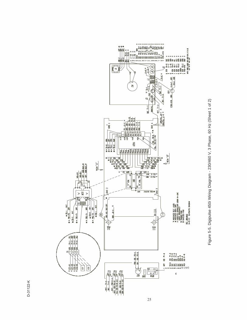
Fig
ure
5-5.
Dig
ipul
se 4
50i W
iring
Dia
gram
- 2
30/4
60 V
, 3
Pha
se,
60 H
z (S
heet
1 o
f 2)
D-3
1122
-K
26
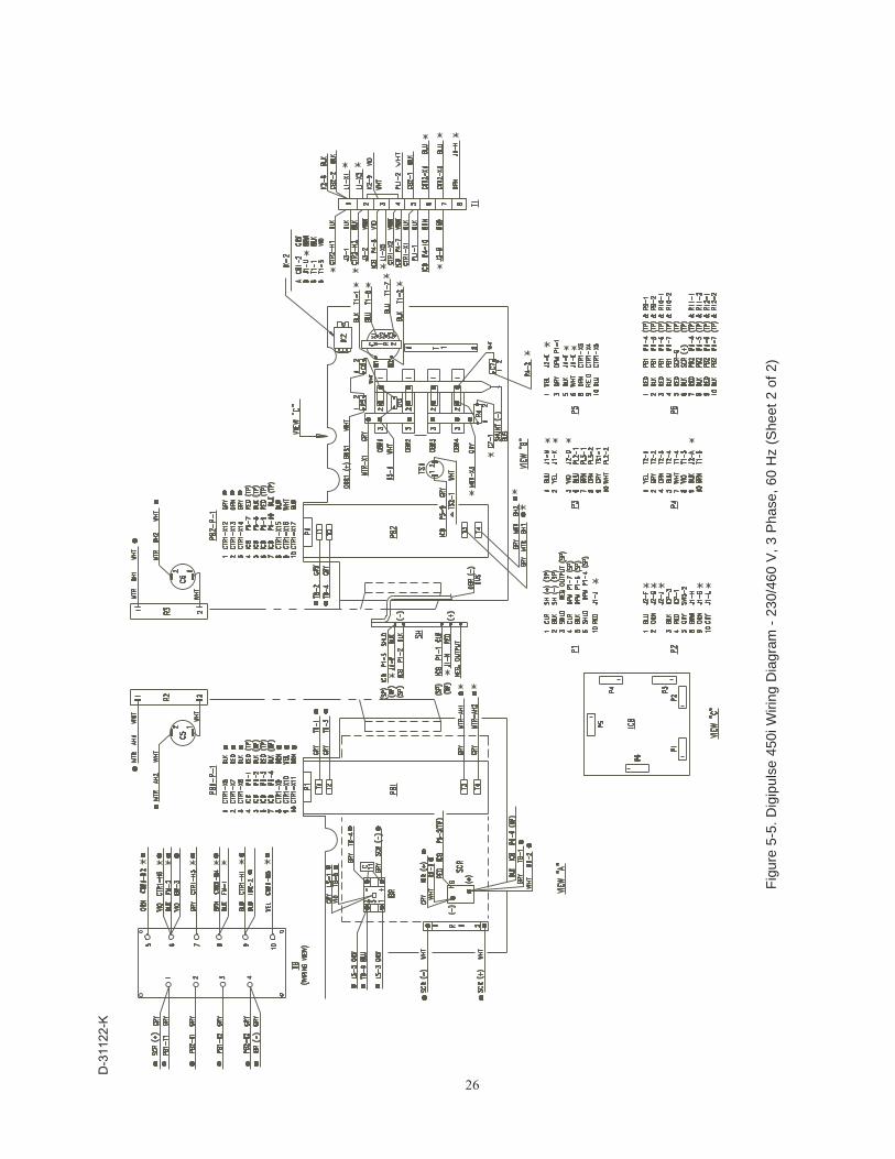
Fig
ure
5-5.
Dig
ipul
se 4
50i W
iring
Dia
gram
- 2
30/4
60 V
, 3
Pha
se,
60 H
z (S
heet
2 o
f 2)
D-3
1122
-K
27
SECTION 6 REPLACEMENT PARTS
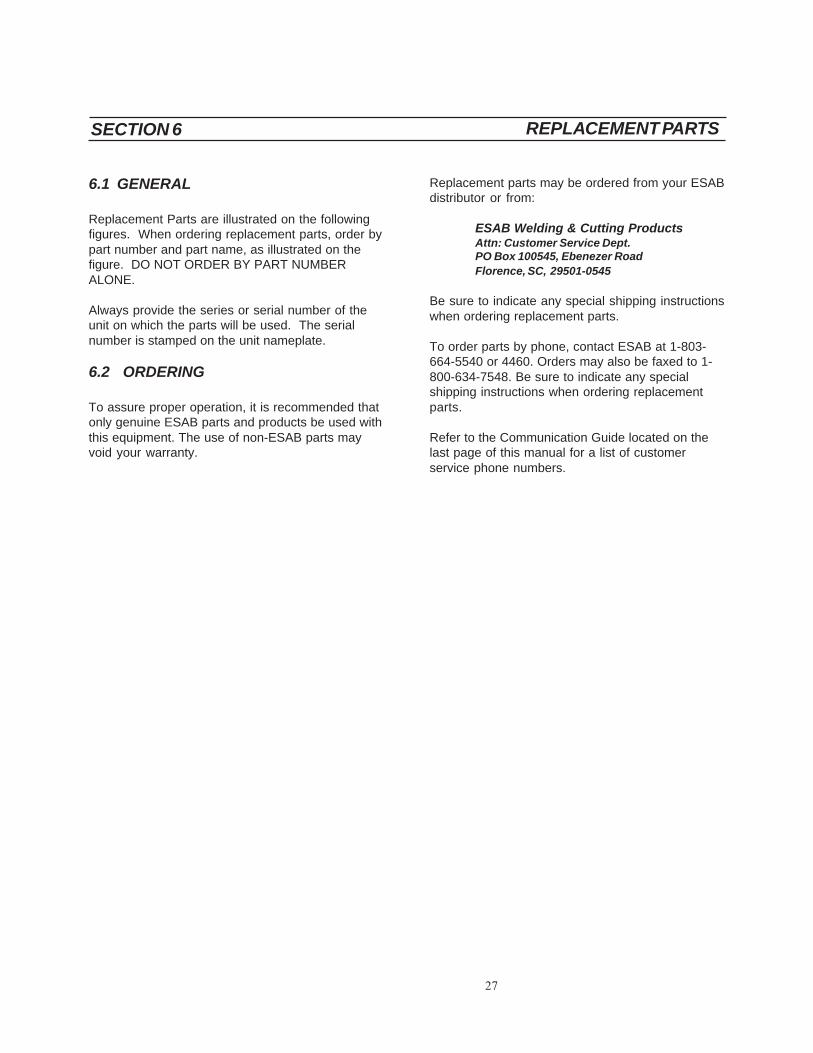
Replacement parts may be ordered from your ESABdistributor or from:
ESAB Welding & Cutting ProductsAttn: Customer Service Dept.PO Box 100545, Ebenezer RoadFlorence, SC, 29501-0545
Be sure to indicate any special shipping instructionswhen ordering replacement parts.
To order parts by phone, contact ESAB at 1-803-664-5540 or 4460. Orders may also be faxed to 1-800-634-7548. Be sure to indicate any specialshipping instructions when ordering replacementparts.
Refer to the Communication Guide located on thelast page of this manual for a list of customerservice phone numbers.
6.1 GENERAL
Replacement Parts are illustrated on the followingfigures. When ordering replacement parts, order bypart number and part name, as illustrated on thefigure. DO NOT ORDER BY PART NUMBERALONE.
Always provide the series or serial number of theunit on which the parts will be used. The serialnumber is stamped on the unit nameplate.
6.2 ORDERING
To assure proper operation, it is recommended thatonly genuine ESAB parts and products be used withthis equipment. The use of non-ESAB parts mayvoid your warranty.

28
$
',*,38/6(����L
�
�
1(*
326
Figure 6-1. Digipulse 450i Power Source (Front View)
1
3
2
6
10
9
8
5
4
7
ITEMNO.
QTYREQ.
PARTNO. DESCRIPTION
CIRCUITSYMBOL
1234
5678910
12111121111
95103195103295104220620189508143112995069431124311283113631130
LAMP, POWER, GREENLAMP, REDMETER, DIGITALINDUCTOR CONTROL POT.KNOB (P/O ITEM NO. 4)RIGHT SIDE PANELFEMALE WELD CONNECTORFRONT PANEL, SILKSCREENEDLEFT SIDE PANELCONTROL PANEL, SILKSCREENEDTOP PANEL
PL1PL2, PL3
DPMICP
13733935
951526
951795
13730611
32059
32056
29
1
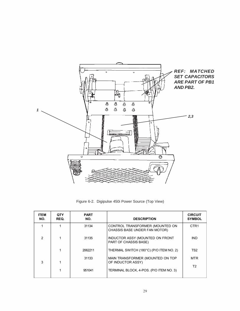
Figure 6-2. Digipulse 450i Power Source (Top View)
2,3
REF: MATCHEDSET CAPACITORSARE PART OF PB1AND PB2.
ITEMNO.
QTYREQ.
PARTNO. DESCRIPTION
CIRCUITSYMBOL
1
2
3
1
1
1
1
1
31134
31135
2062211
31133
951041
CONTROL TRANSFORMER (MOUNTED ONCHASSIS BASE UNDER FAN MOTOR)
INDUCTOR ASSY (MOUNTED ON FRONTPART OF CHASSIS BASE)
THERMAL SWITCH (180°C) (P/O ITEM NO. 2)
MAIN TRANSFORMER (MOUNTED ON TOPOF INDUCTOR ASSY)
TERMINAL BLOCK, 4-POS. (P/O ITEM NO. 3)
CTR1
IND
TS2
MTR
T2
30
1
2
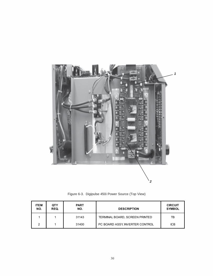
Figure 6-3. Digipulse 450i Power Source (Top View)
ITEMNO.
QTYREQ.
PARTNO. DESCRIPTION
CIRCUITSYMBOL
1
2
1
1
31143
31400
TERMINAL BOARD, SCREEN PRINTED
PC BOARD ASSY, INVERTER CONTROL
TB
ICB

31
Figure 6-4. Digipulse 450i Power Source (Left Side View)
ITEMNO.
QTYREQ.
PARTNO. DESCRIPTION
CIRCUITSYMBOL
14567
11111
674991950702951023
17250005951022
PC BOARD ASSY, POWERCAPACITORSCR MODULERESISTORINPUT BRIDGE MODULE
PB1C9
SCR1R1IBR
1
5
43
2
12345678
95131395105631154
CAPACITORINSULATOR, ISOBARISOBAR, ALUMINUM
111
7,8

32
Figure 6-5. Digipulse 450i Power Source (Right Side View)
1
4
5
6
3
2
10
3,9
1178
ITEMNO.
QTYREQ.
PARTNO. DESCRIPTION
CIRCUITSYMBOL
1234567891011
12311111114
6749911772500595051633938993717635686951085950702
1728201031132951184
PC BOARD ASSY, POWERRESISTORCAPACITORCHOKE COMMON MODETRANSFORMERTERMINAL STRIP, 8-POSTHERMAL SWITCH (80°C)CAPACITOR, .01uF, 125VRESISTOR, 10 OHM 100W NON-IND.SHUNTOUTPUT DIODE
PB2R4,R5C7,C8
L1CTR2
T1TS1C10
R2&R3SH
OBR1-4

33
4
5
7
2,3
8
9
110
6
Figure 6-6. Digipulse 450i Power Source (RearView)
ITEMNO.
QTYREQ.
PARTNO. DESCRIPTION
CIRCUITSYMBOL
12345678910
1111112111
95082268097067938495059297W6395103395012231126951476951475
SWITCH, POWER LINEMOTOR, FANSHROUD, FANBLADE, FANCONNECTOR, CABLE GRIPAUX. RECEPTACLE, 115 V, 10 ACIRCUIT BREAKER, 10 AREAR PANELRECEPTACLE, 14-PIN, STICK/TIGRECEPTACLE, 19-PIN, DIGITAL
LSFM
J3CB1,2
J2J1
952219

34
NOTES

35
REVISIONS
1. Revisions of June 2003 include changes to part numbers in the REPLACEMENT PARTS SECTION on pages28 - 33. Part numbers updated per 8/21/02 mark-up.

36F-15-014-F 06/2003 Printed in U.S.A.
IF YOU DO NOT KNOW WHOM TO CALL
Telephone: (800) ESAB-123/ Fax: (843) 664-4452/ Web:http://www.esab.com
Hours: 7:30 AM to 5:00 PM EST
A. CUSTOMER SERVICE QUESTIONS:Order Entry Product Availability Pricing DeliveryOrder Changes Saleable Goods Returns Shipping Information
Eastern Distribution Center Telephone: (800)362-7080 / Fax: (800) 634-7548
Central Distribution Center Telephone: (800)783-5360 / Fax: (800) 783-5362
Western Distribution Center Telephone: (800) 235-4012/ Fax: (888) 586-4670
B. ENGINEERING SERVICE: Telephone: (843) 664-4416 / Fax : (800) 446-5693Welding Equipment Troubleshooting Hours: 7:30 AM to 5:00 PM ESTWarranty Returns Authorized Repair Stations
C. TECHNICAL SERVICE: Telephone: (800) ESAB-123/ Fax: (843) 664-4452Part Numbers Technical Applications Hours: 8:00 AM to 5:00 PM ESTPerformance Features Technical Specifications Equipment Recommendations
D. LITERATURE REQUESTS: Telephone: (843) 664-5562 / Fax: (843) 664-5548Hours: 7:30 AM to 4:00 PM EST
E. WELDING EQUIPMENT REPAIRS: Telephone: (843) 664-4487 / Fax: (843) 664-5557Repair Estimates Repair Status Hours: 7:30 AM to 3:30 PM EST
F. WELDING EQUIPMENT TRAINING:Telephone: (843)664-4428 / Fax: (843) 679-5864Training School Information and Registrations Hours: 7:30 AM to 4:00 PM EST
G. WELDING PROCESS ASSISTANCE:Telephone: (800) ESAB-123 / Fax: (843) 664-4454 Hours: 7:30 AM to 4:00 PM EST
H. TECHNICAL ASST. CONSUMABLES:Telephone : (800) 933-7070 Hours: 7:30 AM to 5:00 PM EST
ESAB Welding & Cutting Products, Florence, SC Welding EquipmentCOMMUNICATION GUIDE - CUSTOMER SERVICES