DIGIFORCE PROFINET Integration into TIA Portal€¦ · Please select an ethernet port on the S7 and...
16
OPERATION MANUAL DIGIFORCE ® 9307 PROFINET Integration into TIA Portal Manufacturer: © 2016 burster präzisionsmesstechnik gmbh & co kg burster präzisionsmesstechnik gmbh & co kg Alle Rechte vorbehalten Talstraße 1 - 5 Postfach 1432 D-76593 Gernsbach D-76593 Gernsbach Germany Germany Valid from: 15.11.2016 Tel.: (+49) 07224 645-0 Applies to: DIGIFORCE ® 9307-V0X03 Fax.: (+49) 07224 645-88 E-Mail:[email protected] www.burster.com 2564-BA9307PNTIAEN-5770-031520
Transcript of DIGIFORCE PROFINET Integration into TIA Portal€¦ · Please select an ethernet port on the S7 and...

OPERATION MANUAL
DIGIFORCE® 9307
PROFINET Integration into TIA Portal
Manufacturer:
© 2016 burster
präzisionsmesstechnik gmbh & co kg
burster
präzisionsmesstechnik gmbh & co kg
Alle Rechte vorbehalten Talstraße 1 - 5 Postfach 1432
D-76593 Gernsbach D-76593 Gernsbach
Germany Germany
Valid from: 15.11.2016 Tel.: (+49) 07224 645-0
Applies to: DIGIFORCE® 9307-V0X03 Fax.: (+49) 07224 645-88
E-Mail:[email protected]
www.burster.com
2564-BA9307PNTIAEN-5770-031520
2 of 16
1 Integration of DigiForce in TIA Portal V13
This section describes an approach how you can configure the DigiForce via TIA Portal using the example of
S7-1511 CPU. Please note that the samples hier can not be directly used in your production line because
they have beed extremely simplified to reach a better understanding. So you may have to complete it by
checking of status, error, length values etc.
1.1 Creating new project
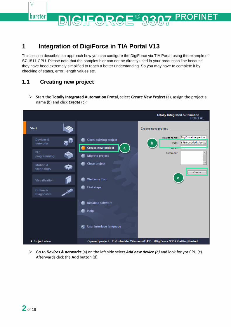
Start the Totally Integrated Automation Protal, select Create New Project (a), assign the project a name (b) and click Create (c):
Go to Devices & networks (a) on the left side select Add new device (b) and look for yor CPU (c). Afterwards click the Add button (d).
a
b
c

3 of 16
1.2 Installation of GSDML files
Go to Options->Manage general station description files (GSD)
b
c
d
a
a

4 of 16
Navigate to your DigiForce GSDML directory (a)(you will find the GSDML files on burster DVD that you got with your DigiForce device or on burster.com), select the GSDML file (b) and click Install (c)
1.3 Creation of network connections
Double click Device Configuration (a) in the project tree und switch to Topology (b) view:
a
b
c

5 of 16
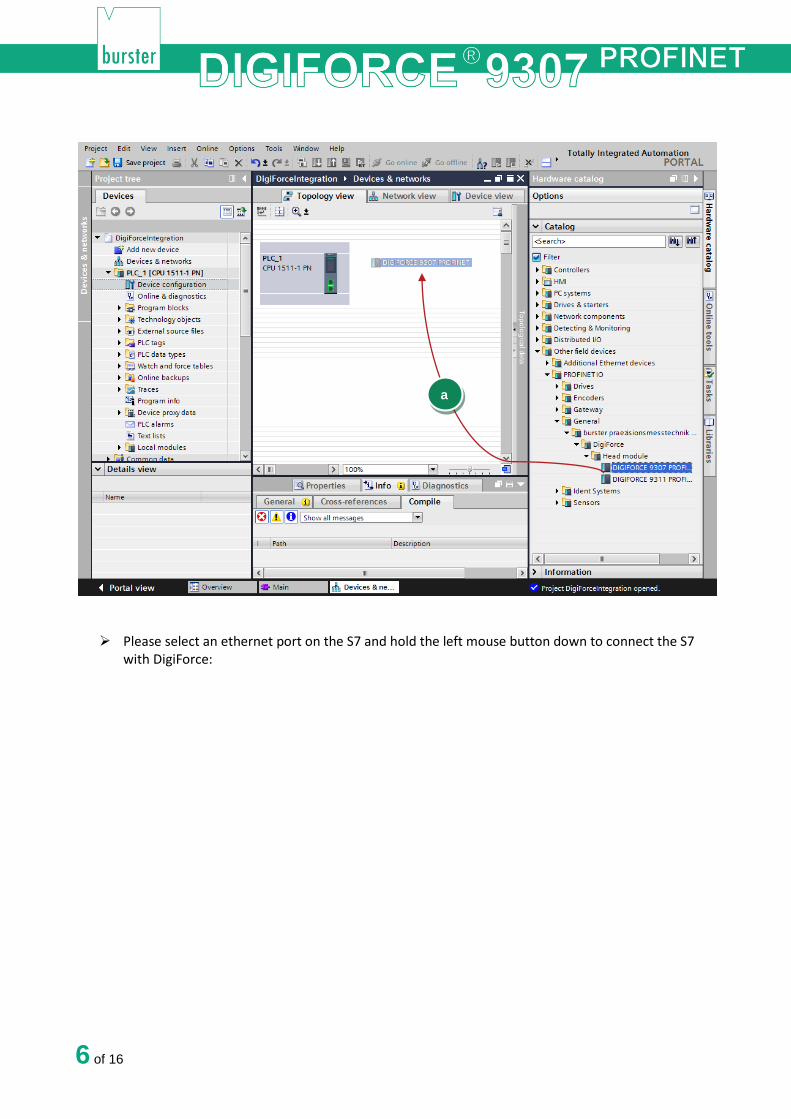
Now select the DigiForce device in the catalog and drag & drop it into the working area:
a
b
6 of 16
Please select an ethernet port on the S7 and hold the left mouse button down to connect the S7 with DigiForce:
a

7 of 16
Change now to Network view (a) to assign a controller to the DigiForce. Click on the link “Not assigned” (b) of DigiForce and select your controller (c):
a

8 of 16
Check if devices also connected physically to the right ports. You find the port number assignment
in the section 3.3 Port-Identification.
1.4 Create a sample program:
In this section you will learn how to create a simple program to start and stop a measurement periodically. You will need to refer to sections 7.2 PLC inputs and 7.3 PLC outputs to understand the meaning of inputs and outputs bytes.
Expand the tree node Program blocks in the Project tree and double click Add new block):
a
b
c

9 of 16
Select in the new widnow Organization block (a) and then Cyclic interrupt (b). As language set SCL (c), change the cyclic time to 1.000.000 µs (d) and click OK (e):

10 of 16
Type in the following source code in the code fild of the new block:
IF %Q259.0 = TRUE THEN
%Q259.0 := FALSE;
ELSE
IF %I256.0 = FALSE THEN
RETURN;
END_IF;
%Q259.0 := TRUE;
END_IF;
// is IN_START (measurement start) set? // IN_START (measurement start) is set, then reset it // IN_START is not set // is OUT_READY (DigiForce ready for measurement) set? // If not - // return
// set IN_START(measurement start)
Please note: the addresses may be different. You have to check them in the Device view->Device
overview of the DigiForce 9307
a
b
c
d
e

11 of 16
You will also see that the TIA-Editor replaces the input/aoutput addresses with tags. You can change
the tags names in PLC Tag table:
Bevore you load the project into the CPU you have to set the IP addresses of your controller and your device. To do this please go to Device view (a) and select Ethernet addresses (b) in General tab. Set now a desired IP-Address (c):

12 of 16
To load the configuration into the CPU select it first and then go to Online->Download to device
and click on Start search (a) to look for your controller. Then select the controller and click on Load (b):
a
b
c

13 of 16
The DigiForce starts now a new measurement, wait a second, and stops the measurement, wait a
second and strarts the measurement again and so on.
Note: Make sure that PROFINET Control is enabled in DigiForce. Foe datails see chapter
Configuration menu in DIGIFORCE® 9307 of the DIGIFORCE® 9307 PROFINET manual
1.5 Further Examples
1.5.1 Reading and Writing of string data types
In this example we perform a read access on slot 30/Subslot 1/index 10 to get the device type of DigiForce
and then we will set the first 9 characrters of this string as DigiForce station name on Slot 30/Subslot 1/Index
19. For these acyclic operations you will need an instance of RDREC und WRREC blocks. You can see the
new station name in the info menu of DigiForce.
PLC parameters table:
a
b

14 of 16
Sourcecode:
REPEAT
"RDREC_DB"(REQ:=TRUE,
ID:=268, // 268: HW-ID for General Settings (see device properties)
INDEX:=10, // Index 10: Device Detection
MLEN:=18, // Max. lenth of data to read
VALID=>#Valid, // New Data Received and valid
BUSY=>#Busy, // Read not completed yet
ERROR=>#Error, // Error
STATUS=>#Status, // State
LEN=>#lenRead, // Number of bytes was read from device
RECORD:= #data); // Array[0..18] of Byte
UNTIL NOT #Busy
END_REPEAT;
IF #Error = TRUE OR #Status <> 0 THEN
RETURN;
END_IF;
REPEAT
"WRREC_DB"(REQ:=TRUE,
ID:=268, // 268: HW-ID for General Settings (see device properties)
INDEX:=19, // Index 19: Station Name
LEN:=9, // Lenth of date to write
DONE=>#Done, // Write done
BUSY=>#Busy, // Write not completed yet
ERROR=>#Error, // Error
STATUS=>#Status, // State
RECORD:=#data); // Write the data has being read in RDREC_DB (first 9 Bytes)
UNTIL NOT #Busy AND #Done
END_REPEAT;
1.5.2 Retrieving of measurement results
Note: The reading of all X- or Y-Coordinates of a curve is only supported in the DigiForce PROFINET
Firware V16.0.1 and higher.
This example shows you how to read the X-Coordinates of the current curve.
PLC parameters tables:

15 of 16
Sourcecode:
REPEAT
"WRREC_DB"(REQ := TRUE,
ID := 454,
INDEX := 10,
LEN := 2,
DONE => #Done,
BUSY => #Busy,
ERROR => #Error,
STATUS => #Status,
RECORD := "Data".data);
UNTIL NOT #Busy AND #Done
END_REPEAT;
IF #Error = TRUE OR #Status <> 0 THEN
RETURN;
END_IF;
REPEAT
"RDREC_DB"(REQ := TRUE,
ID := 454,
INDEX := 10,
MLEN := 4,
VALID => #Valid,
BUSY => #Busy,
ERROR => #Error,
STATUS => #Status,
LEN => #lenRead,
// Write access to index 10 to prepare the curve
// Hardware-ID
// Index
// Length in bytes to write
// Any 2 bytes to prepare the curve
// If write failed -> return
// Read the number of curve values
// Hardware-ID of slot 132
// Index
// Max. length to read
// Number of bytes read

16 of 16
RECORD := #lastIndex);
UNTIL NOT #Busy
END_REPEAT;
#lastIndex := SHR(IN := #lastIndex, N := 16);
IF #Error = TRUE OR #Status <> 0 OR #lenRead <> 2 OR
#lastIndex = 0 THEN
RETURN;
END_IF;
REPEAT
"RDREC_DB"(REQ := TRUE,
ID := 454,
INDEX := 11,
MLEN := 20000,
VALID => #Valid,
BUSY => #Busy,
ERROR => #Error,
STATUS => #Status,
LEN => #lenRead,
RECORD := "Data".data);
UNTIL NOT #Busy
END_REPEAT;
IF #Error = TRUE OR #Status <> 0 OR #lenRead < 4
THEN RETURN;
END_IF;
FOR #i := 0 TO DWORD_TO_INT(#lenRead - 1) BY 4 DO
#measVal := 0;
#tmp := BYTE_TO_DWORD("Data".data[#i]);
#measVal := #measVal + SHL(IN := #tmp, N := 24);
#tmp := BYTE_TO_DWORD("Data".data[#i + 1]);
#measVal := #measVal + SHL(IN := #tmp, N := 16);
#tmp := "Data".data[#i + 2];
#measVal := #measVal + SHL(IN := #tmp, N := 8);
#measVal := #measVal + "Data".data[#i + 3];
"Data".coordinates[#i / 4] :=
DWORD_TO_REAL(#measVal);
END_FOR;
// Number of values in the curve - 1
// upto and including DigiForce field bus firmware
FW-201601 we have to use DWord to get U16 Types
from DigiForce und shift left the result by 2 bytes
// If read failed -> return
// Read access to read out curve coordinates
// Hardware-ID of slot 132
// Index
// Max. length to read
// Number of bytes read
// Array to store the read coordinates
// If read failed -> return
// Write bytes to DWORD and convert to Real
// Shift left the value by 24 bit
// Shift left the value by 16 bit
// Shift left the value by 8 bit
// Convert to Real and store in MeasValues[] Array