Diesel and Gas Turbine Nanoparticle Density Distribution ...J-85 turbojet –influence of fuel type...
25
Diesel and Gas Turbine Nanoparticle Density Distribution Measurements David Kittelson Department of Mechanical Engineering University of Minnesota Robert Giannelli, John Kinsey, and Jeff Stevens United States Environmental Protection Agency Robert Howard, Brandon Hoffman U. S. Air Force, Arnold Engineering Development Complex (AEDC) 21st ETH Conference on Combustion Generated Nanoparticles Zurich, Switzerland June 19 th – 22 nd 2017 T. E. Murphy Engine Research Laboratory
Transcript of Diesel and Gas Turbine Nanoparticle Density Distribution ...J-85 turbojet –influence of fuel type...
Diesel and Gas Turbine Nanoparticle Density Distribution Measurements
David KittelsonDepartment of Mechanical Engineering
University of Minnesota
Robert Giannelli, John Kinsey, and Jeff StevensUnited States Environmental Protection Agency
Robert Howard, Brandon HoffmanU. S. Air Force, Arnold Engineering Development Complex (AEDC)
21st ETH Conference on Combustion Generated Nanoparticles
Zurich, Switzerland
June 19th – 22nd 2017
T. E. Murphy Engine Research Laboratory

AcknowledgementsThis work is part of the large study “Variable Response In Aircraft non-volatile PM (nvPM) Testing (VARIAnT) 3” with many participants• U. S. Environmental Protection Agency National Risk Management Research Laboratory [NRMRL]--John
Kinsey
• U. S. Environmental Protection Agency National Vehicle and Fuel Emissions Laboratory [NVFEL]--Bob
Giannelli, Nick Bies, Jeff Stevens, and Scott Agnew
• U. S. Air Force, Arnold Engineering Development Complex (AEDC)--Robert Howard, Brandon Hoffman, Brad
Winkleman, Robert Baltz, Mary Forde, Todd VanPelt, and Test Team
• Artium Technologies--Greg Payne and Will Bachalo
• AVL Test Systems, Inc.--Richard Frazee
• Aerodyne Research--Tim Onasch and Andrew Freedman
• University of Minnesota--David Kittelson
• Southwest Research Institute [SwRI]--Imad Khalek, Huzeifa Badshah, Daniel Preece, and Vinay Premnath
• WMS Engineering--Bill Silvis
T. E. Murphy Engine Research Laboratory

VARIAnT 3 Overall Study Goals
• Investigate the response of black carbon instruments: LII, MSS, MSS+, and CAPS PMssa• As challenged by various Diffusion Flame Combustion Aerosols (DFCASs) and fuels
(anticipating changes in size distribution, apparent density, and morphology of the test aerosol particles)
• Directly varying the concentration at each steady-state DFCAS operating condition
• Varying the organic carbon/elemental carbon (OC/EC) ratio of the test aerosol with and without an inline catalytic stripper
• Collect particle samples for assessment of morphology using TEM analysis
• Perform CPMA/DMA measurements for assessment of particle density versus size
• If possible, assess whether the CAPS PMssa and LII and MSS with sensitivity improvements still meet type certification requirements
T. E. Murphy Engine Research Laboratory
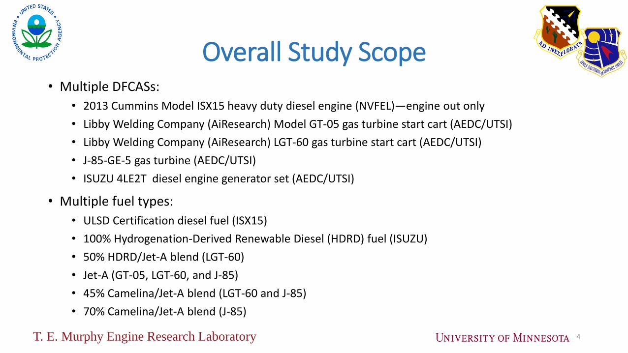
Overall Study Scope• Multiple DFCASs:
• 2013 Cummins Model ISX15 heavy duty diesel engine (NVFEL)—engine out only
• Libby Welding Company (AiResearch) Model GT-05 gas turbine start cart (AEDC/UTSI)
• Libby Welding Company (AiResearch) LGT-60 gas turbine start cart (AEDC/UTSI)
• J-85-GE-5 gas turbine (AEDC/UTSI)
• ISUZU 4LE2T diesel engine generator set (AEDC/UTSI)
• Multiple fuel types:
• ULSD Certification diesel fuel (ISX15)
• 100% Hydrogenation-Derived Renewable Diesel (HDRD) fuel (ISUZU)
• 50% HDRD/Jet-A blend (LGT-60)
• Jet-A (GT-05, LGT-60, and J-85)
• 45% Camelina/Jet-A blend (LGT-60 and J-85)
• 70% Camelina/Jet-A blend (J-85)
4T. E. Murphy Engine Research Laboratory

Motivation for density measurements
• New standards for aircraft particle mass. Particle number, and CO2 are planned for 2020
• Particle standards are to be based on solid particle number larger than 10 nm , and solid particle mass
• Sampling conditions are brutal, imagine sampling from an exhaust stream at Mach 1 and 900 K with engines producing up to 530,000 N (120,000 lbf) thrust
• This necessitates very long sampling lines, up to 35 m, leading to significant particle losses, especially for particle number
• Thus line loss corrections must be made – these corrections require knowledge of (among other things) particle density
5T. E. Murphy Engine Research Laboratory

Long sampling lines necessitate a line loss correction which requires knowledge of density
SAE International Aerospace Information Report 6241T. E. Murphy Engine Research Laboratory
Recommended aircraft sampling line configuration (SAE International Aerospace Information Report 6241)

Line loss correction method• Size dependent corrections are required but the
SAE E-31 committee decided against direct particle size measurement
• The only measurements available are nonvolatile particle mass and number (nvPMand nvPN)
• Requires well validated line loss model, currently uses UTRC model
• Assumptions• No nucleation or coagulation• Engine exit plane size distribution is lognormal
• Effective particle density and sg are known
• The remaining unknowns are the exit plane number concentration and geometric mean diameter.
• These values are varied in an iterative solution until the exit plane distribution, before line losses yields the observed downstream nvPM and nvPN
T. E. Murphy Engine Research Laboratory

Preliminary Draft - DO NOT Distribute 8
Sampling System Schematic for AEDC
Manifold Outlets
T = Thermocouple Temperature Measurement
P = Pressure Measurement
MGA = FTIR for Raw CO2 & other gaseous concentrations)
TW = External sampling tube temperature
CAP = Capped Line
V = Ball Valves
NV = Needle Valves
PD = Primary Diluter
PDVV = Primary Diluter Vent Valve
PDVNV = Primary Diluter Vent Needle Valve
SD = Secondary Diluter
SDVV = Secondary Diluter Vent Valve
SDVNV = Secondary Diluter Vent Needle Valve
= Dark Black denotes line segments actively heated to ~160 °C
= Gray denotes line segments actively heated to ~ 60 °C
= Light blue denotes line segment not actively heated (some wrapped)

Approach
For each combustion source particle properties were varied by
• Changing load
• Changing fuel
• Using a catalytic stripper (CS) to remove adsorbed semivolatile matter and separate semivolatile particles• CS operated at 350 C, some material tightly bound to particles may remain
• Particles measured downstream of CS are defined as nonvolatile PM (nVPM) or “solid” particles
• Concentration varied over wide range by varying dilution ratio
9T. E. Murphy Engine Research Laboratory

10
Apparatus for CPMA measurements
Adapted from Olfert, et al., JAS 37 (2006) 1840-1852
Sample in
T. E. Murphy Engine Research Laboratory

Typical data: LGT-60 start cart bleed air (load) on
intensity x bar ln x bar sigma ln sigma pre exp ChiSqrTotal
122.52 0.0143 -4.25 1.16 0.15 2.74 2.43E+04
average scan 1 scan 2
mean 0.0141 0.0145 0.0136 Scan 1 Particle diameter (nm): 31.96
mode 0.0157 0.0158 0.0155 Scan 2 Particle diameter (nm): 31.98
median 0.0143 0.0148 0.0137 average 31.97
Datum# Time Mass (fg)
Mass Spectral
Density
(dN/dLog(Mp*)/cc) lognorm ChiSqr
1 14:03:51 4.23E-02 0.00E+00 2.87E-04 8.23E-08 V 1.71E+04 nm3 density
2 14:04:06 3.68E-02 0.00E+00 8.53E-03 7.27E-05 1.71E-23 m3
3 14:04:20 3.19E-02 0.00E+00 1.57E-01 2.46E-02 m 1.43E-02 fg
4 14:04:34 2.78E-02 2.92E+00 1.79E+00 1.29E+00 1.43E-20 kg 8.34E+02 kg/m3
5 14:04:49 2.41E-02 8.12E+00 1.29E+01 2.30E+01
6 14:05:04 2.09E-02 3.51E+01 5.92E+01 5.84E+02
7 14:05:17 1.81E-02 2.16E+02 1.71E+02 2.02E+03
8 14:05:30 1.58E-02 3.11E+02 2.99E+02 1.43E+02
9 14:05:43 1.38E-02 2.78E+02 3.31E+02 2.85E+03
10 14:05:57 1.18E-02 1.63E+02 2.21E+02 3.38E+03
11 14:06:10 1.03E-02 5.87E+01 9.61E+01 1.40E+03
12 14:06:24 8.86E-03 1.76E+01 2.28E+01 2.78E+01
13 14:06:37 7.80E-03 1.63E+00 4.45E+00 7.94E+00
14 14:06:50 6.75E-03 0.00E+00 4.46E-01 1.99E-01
15 14:07:03 5.82E-03 0.00E+00 2.50E-02 6.25E-04
16 14:07:17 5.06E-03 0.00E+00 9.84E-04 9.68E-07
17 14:07:30 0.004557 2.959 6.75E-05 8.76E+00
18 14:07:44 0.003793 0 3.19E-07 1.02E-13
19 14:07:57 0.003332 8.461 4.50E-09 7.16E+01
20 14:08:10 0.002913 0 3.56E-11 1.27E-21
21 14:08:28 0.002555 0 2.10E-13 4.42E-26
22 14:08:48 0.002207 0 4.21E-16 1.78E-31
23 14:09:07 0.001977 0 2.83E-18 8.01E-36
T. E. Murphy Engine Research Laboratory

LGT-60 Start Cart – a small gas turbine engine
LGT-60 with/without CS, total (including semi-volatile) and solid particle density
LGT-60 with CS, variable load and fuel, solid particle density
T. E. Murphy Engine Research Laboratory

J-85 turbojet tests – influence of fuel type and engine load (10 PLA = idle, 90 PLA = max thrust)
J-85 Jet-A fuel, variable thrust without CS, total density
J-85 Camelina blend fuel, variable thrust without CS, total density
T. E. Murphy Engine Research Laboratory

J-85 turbojet tests – influence of fuel type and engine load on solid particle density profiles
J-85 jet-A fuel, variable thrust with CS, solid density
J-85 Camelina blend fuel, medium and high thrust with CS, solid density
T. E. Murphy Engine Research Laboratory
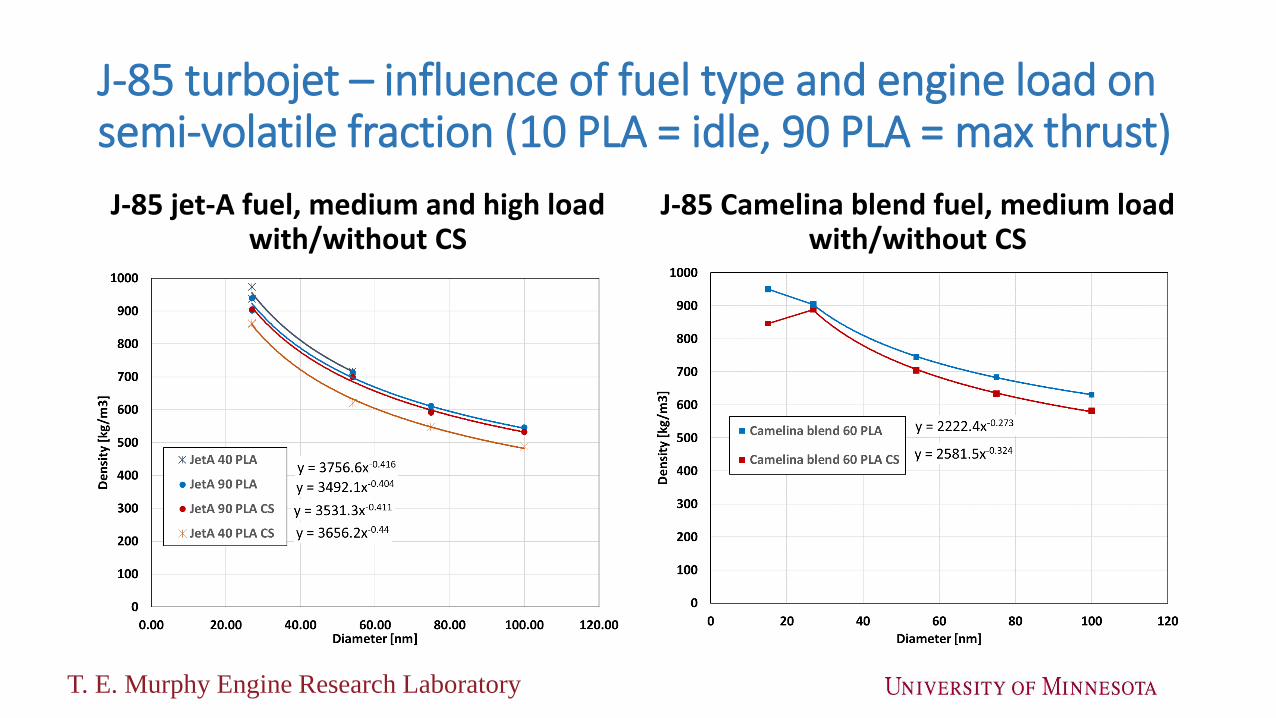
J-85 turbojet – influence of fuel type and engine load on semi-volatile fraction (10 PLA = idle, 90 PLA = max thrust)
J-85 jet-A fuel, medium and high load with/without CS
J-85 Camelina blend fuel, medium load with/without CS
T. E. Murphy Engine Research Laboratory

Isuzu diesel genset compared to J-85
J-85 Jet-A fuel, variable thrust, with/without CS
Isuzu diesel generator, HDRD fuel, idle and high power, with/without CS
T. E. Murphy Engine Research Laboratory

Size distributions – IGT-60 and J-85 with/without CS
IGT-60 loaded (bleed air on) J-85 at medium thrust setting
17T. E. Murphy Engine Research Laboratory

Size distributions – Isuzu Genset with/without CS
Isuzu diesel generator, Idle, HDRD fuel Isuzu diesel generator, 20 kW, HDRD fuel
T. E. Murphy Engine Research Laboratory

Impact of density on line loss correction factors
Impact of density on estimated line loss correction factors, Kn for number and Km for mass
Densityg/cm3
Kn Km
1.0 6.8 1.5
0.72 5.59 1.42
% Error 22 6
T. E. Murphy Engine Research Laboratory
Summary
• Density shows inverse power law size dependence• Density proportional to Dp-n where n ~ 0.3 to 0.4• This corresponds to a mass mobility relation, m proportional to Dp(3-n)
• Up to 20% particle mass decrease association with removal of semivolatile material by the CS at 350 C
• Nonvolatile particle mass more dependent on load and fuel than total particle mass
• Accurate knowledge of density required for aircraft line loss correction. For the example case here incorrect density led to• 22% overestimate of line loss number correction• 6% overestimate of line loss mass correction
T. E. Murphy Engine Research Laboratory

Questions

Supporting Information
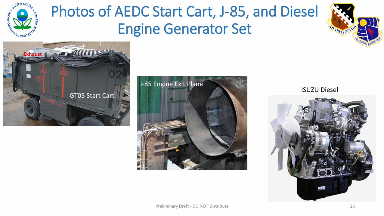
Photos of AEDC Start Cart, J-85, and Diesel Engine Generator Set
23Preliminary Draft - DO NOT Distribute
J-85 Engine Exit Plane
GT05 Start Cart
Exhaust
ISUZU Diesel

24
Sample Plenum Design
from front end
To instruments via 3/8” OD lines
(Swagelok reducer/diffuser
fittings when needed)
~65”
~10”
Probe depth into chamber
12”• Cone consists of 3 sections+1/2” inlet welded together• 2 sections purchased, 1 fabricated in AA• Cone welded to ~1” quick clamp sanitary tubing• Cone, 12”, and 18” sections connected via clamp & gasket• 18” section connected via clamp & gasket to end cap with
probes• Probe tubes of different diameters and assembly of end cap
fabricated at NVFEL
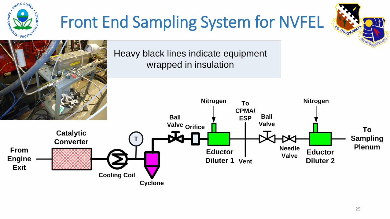
Front End Sampling System for NVFEL
25
To
Sampling
Plenum
Vent
Catalytic
Converter
Ball
Valve Orifice
Ball
Valve
Eductor
Diluter 1
Nitrogen Nitrogen
Eductor
Diluter 2
Cyclone
From
Engine
Exit
T
Cooling Coil
Needle
Valve
To
CPMA/
ESP
Heavy black lines indicate equipment
wrapped in insulation