Diels-Alder reactions in synthesis and method development
122
Diels-Alder reactions in synthesis and method development: Development of a synthetic pathway to decalin terpenoids and evaluation of phosphordiamides as Diels-Alder catalysts Dissertation for the degree of Philosophiae Doctor Jakob Wåhlander Department of Chemistry Faculty of Mathematics and Natural Sciences University of Oslo 2018
Transcript of Diels-Alder reactions in synthesis and method development

Diels-Alder reactions in synthesis and method development:
Development of a synthetic pathway to decalin terpenoids and evaluation of
phosphordiamides as Diels-Alder catalysts
Dissertation for the degree of Philosophiae Doctor
Jakob Wåhlander
Department of Chemistry Faculty of Mathematics and Natural Sciences
University of Oslo
2018

© Jakob Wåhlander, 2018
Series of dissertations submitted to the Faculty of Mathematics and Natural Sciences, University of Oslo No. 2018
ISSN 1501-7710
All rights reserved. No part of this publication may be reproduced or transmitted, in any form or by any means, without permission.
Cover: Hanne Baadsgaard Utigard. Print production: Reprosentralen, University of Oslo.
Diels-Alder reactions in synthesis and method development: Development of a synthethic
pathway to decalin terpenoids and evaluation of phosphordiamides as Diels-Alder catalysts

III
This thesis is dedicated to my grandfather, Lars Wåhlander. The only other chemist in my
immediate family.
Mitt lab, det har tre väggar. Den fjärde är vakant. Så går det om man brukar, azid som
reaktant.
--Unknown genius.


IV
Table of Content
Table of Content ..................................................................................................................................... IV
Acknowledgements ................................................................................................................................ VI
Summary .............................................................................................................................................. VIII
Graphical abstracts ................................................................................................................................. IX
Abbreviations .......................................................................................................................................... X
Chapter 1 – Background .......................................................................................................................... 1
1.1 – The planned synthesis of Asmarines .......................................................................................... 1
1.1.1 Our synthesis .......................................................................................................................... 7
1.2 – The Diels-Alder reaction ............................................................................................................. 9
1.3 – Organocatalyzed reactions ....................................................................................................... 10
1.4 – Organocatalysts as Diels-Alder catalyst .................................................................................... 12
1.5 – General aims of the study ........................................................................................................ 15
1.6 – References ................................................................................................................................ 16
Chapter 2 – Experimental evaluation of phosphordiamides as Diels-Alder catalysts. .......................... 18
2.1 - Introduction ............................................................................................................................... 18
2.2 – Results and discussion .............................................................................................................. 20
2.2.1 – The initial synthesis of two phosphordiamides for catalytic testing ................................. 20
2.2.2 – Evaluation of the phosphordiamides using a small UV-absorbing indicator..................... 21
2.2.3 – Evaluation of the reactivity of phosphordiamides using 2-Methoxycinnaldehyde and
Cyclopentadiene ............................................................................................................................ 22
2.2.4 – New catalysts and a third attempt at evaluation of the reactivity using Methyl vinyl
ketone ............................................................................................................................................ 23
2.3 – Summary and conclusions ........................................................................................................ 25
2.4 – Experimental section ................................................................................................................ 25
2.5 – References ................................................................................................................................ 28
Chapter 3 – A computational study of phosphoramides as Diels-Alder catalysts ................................ 29
3.1 – Introduction .............................................................................................................................. 29
3.1.1 –Linear free energy relationships ......................................................................................... 30
3.2 – Results and discussions ............................................................................................................ 31
3.2.1 – Transition states and structural relationships to size in cycloaddition energy barriers .... 33
3.2.2 – LFER-analysis of the cycloaddition energy barriers ........................................................... 37
3.2.3 – Stereoselectivity ................................................................................................................ 45
3.3 – Summary and conclusions ........................................................................................................ 48

V
3.4 – Experimental section ................................................................................................................ 49
3.5 - References ................................................................................................................................. 50
Chapter 4 – Synthesis directed towards a Decalin Terpenoid .............................................................. 51
4.1 – Introduction .............................................................................................................................. 51
4.1.1 - Lewis acid catalyzed Diels-Alder reactions using conjugated carbonyl compounds ......... 51
4.1.2 – Imidazolidinone catalysts .................................................................................................. 52
4.2 - Early attempts of Diels-Alder reactions using several different dienes .................................... 53
4.3 - Attempted synthesis of the Diels-Alder adducts 215 and 219a and b using the diene 212 ..... 56
4.3.1 - Synthesis of the third diene 212 ........................................................................................ 57
4.3.2 - Diels-Alder reaction with the diene 212 ............................................................................ 57
4.4 - Further work on the diene 212 ................................................................................................. 74
4.5 - Summary and conclusions ......................................................................................................... 82
4.6 – Experimental section ................................................................................................................ 83
4.6.1- Compounds ......................................................................................................................... 83
4.6.2 – Tables ................................................................................................................................. 93
4.6.3 – Computational work .......................................................................................................... 95
Chapter 5 – Future prospects ................................................................................................................ 99
5.1 – Introduction .............................................................................................................................. 99
5.2 – Terpenoid synthesis .................................................................................................................. 99
5.3 – Phosphordiamides .................................................................................................................. 102
5.3 - References ............................................................................................................................... 107
Appendix 1 ........................................................................................................................................... 108
Appendix 2 ........................................................................................................................................... 126

VI
Acknowledgements
This has been a long journey, but now it is finally over. First and foremost I’d like to thank
my supervisors professors Mohamed Amedjkouh, Lise-Lotte Gundersen and David Balcells.
Without the three of you, this thesis would not exist.
There have also been a number of people who has been maintaining all the instruments that
I’ve been using. I would therefore like to extend great thanks to Professor Frode Rise and
senior engineer Dirk Petersen from the NMR-lab, and Dr. Osamu Sekiguchi and the MS-
group from the MS-lab. I also feel that I should thank the High Performance Computing team
for their assistance with the trickier parts of Abel.
A literal army of people, besides my supervisors, has also read this thesis forwards and
backwards and probably sideways as well. So a great thanks to, in no particular order, Fredrik
Adås, Bora Sieng, Kim Alex Fredriksen, Emily McHale, Håkan Wåhlander and Håkon
Sætren Gulbrandsen.
Onwards, I would like to thank the three ladies who shared an office with me at different
times during my stay here. So, thank you Britt Paulsen, Charlotte Herstad (previously Miller)
and Elahe Jafari. The office is a great deal lonelier without you!
I have also had many lovely group mates that have made my time at UiO truly worthwhile. In
the Amedjkouh group there is Bora (again), Kim (again), Matias Funes Maldonado, Carlo
Romagnoli, Eirik Mydske Thoresen, Øyvind Jacobsen, Giuseppe Rotunno, Isabelle Geiz and
a number of master students and bachelor students too great to mention here. In the
Gundersen group there is Britt (again), Håkon (again), Matthew Read, Jindrich Kania, Martin
Hennum, Tushar Mahajan and once again countless master students and bachelor students. In
the wider context of Organic Chemistry, Catalysis and Kjemisk Institutt, I would also like to
mention Peter Molesworth, Christian Schnaars, Thomas Ilhe Aarhus, Charlotte (again), Elahie
(again), Emily (again), Marte Sofie Holmsen, Knut Hylland, Franziska Ihlefeldt, Christiano
Glessi, Vladimir Levchenko, Eirin Langseth, Kenneth Aase Kristoffersen, Steffi and Fredrik
Lundvall, Chris Thomas, Pekka Tapio, Caitlin McQueen and all my acquaintances down at
Catalysis. Many thanks to all of you! Tore-Bonge Hansen gets a particular mentioning for
being a good sport.
I have also been teaching together with a number of excellent teaching assistants that have
worked diligently to make sure that the teaching labs have been up to snuff and made my
teaching experience some of the best parts of working here. So thank you, Massoud Kaboli,
El Houssine Merrachi, Benedicte Vollund, Jonas Andre Olsen and Per Olav Kvernberg. I
have also benefitted from a well-stocked central storage so a great thanks to Runar Staveli,
Hilda Marie Kvila, Magda Grabska-Makulus, Dariusz Makulus and Thea Fossum Moen. I
similar thanks is extended a thanks to the administrative personel; Bjørg Irene Osvik, Line
Trosterud Resvold and Thea (again). Especial thanks to Line Altern Halvorsen Valbø for her
support. There has also been some excellent administrative support from Gloria Bostick and
Kathrine Lang down at the Catalysis group. Many thanks to you too!

VII
A very special thanks goes out to Ruth-Anne Tomtum, Sunniva Olivia Rørvik and Andrew
Harar. You all know why!
Finally, I would like to thank all friends not already mentioned here for putting up with my
complaints. You have all contributed to keeping me sane during these years. A great thanks to
all of you, no-one mentioned but most certainly no-one forgotten! The same goes for my
mother Karin, my father Håkan (again) and my sister Jenny and the rest of my extended
family! Thank you all so much!
Jakob Wåhlander
-

VIII
Summary
This thesis has got two parts within the common theme of Diels-Alder reactions. One part
starts with the group of natural products called asmarines. These compounds, which were
found in the red sea sponges, were believed to have anti-cancer properties. However a
synthetic pathway to these compounds does as of yet not exist. A potential synthetic pathway
for a fragment of the asmarines was devised, using a Diels-Alder reaction in a crucial step.
The other part starts with thioureas, a class of compounds that act as Diels-Alder catalysts by
way of hydrogen bond activation of and α,β-unsaturated carbonyl compound. A new, but
similar, phosphordiamide based framework that was hypothesized to act in a similar manner
to the thioureas. It was thought that a functioning phosphordiamide catalyst could be used in
the crucial Diels-Alder reaction of the asmarine fragment. A more in detail description is
found in Chapter 1.
In Chapter 2 the initial attempts at producing a functional phosphordiamide catalyst are
presented. A few simple catalysts are produced and evaluated using several different systems.
The compounds are however unsuccessful as Diels-Alder catalysts. Further studies of
phosphordiamides can be found in Chapter 3 which deals with a computational study a new
set of phosphordiamide catalysts, with more successful results. The Chapter 4 deals with the
previously discussed synthetic pathway of an asmarine fragment. The idea of using a
phosphordiamide as a catalyst was discarded in favor of a Lewis acid catalyst. Though the
synthesis of the fragment was not complete, the main Diels-Alder step was eventually
overcome and several more steps were completed with good yields. The final Chapter 5
describes a possible continuation to both projects.

IX
Graphical abstracts
Chapter 2
Chapter 3
Chapter 4

X
Abbreviations
AcOH – Acetic acid
Alloc – Allyloxycarbonyl
Ar – Argon
Bn – Benzyl
Boc – tert-Butyloxycarbonyl
Bu4NI – Tetrabutylammonium iodide
n-Buli – n- Butyllithium
BuOH – Butanol
CBS – Corey, Bakshi and Shibata catalyst
COSY – Correlation Spectroscopy
Cp – Cyclopentadienyl
DCE – Dichloroethane
DFT – Density Function Theory
DIAD – Diisopropyl azodicarboxylate
DIBALH – Diisobutlaluminium hydride
DMAP – 4-Dimethylaminopyridine
DMF – Dimethyl formamide
DMSO – Dimethyl sulfoxid
ee – Enantiomeric excess
Et – Ethyl
Et2O – Diethyl ether
Et3N – Triethyl amine
EtOAc – Ethyl acetate
EtOH – Ethanol
eV – electron volt
h – hour

XI
HDMS – Hexamethyldisilazane
HMPA – Hexamethylphosphoramide
HOMO – Highest Occupied Molecular Orbital
LDA – Lithium diisopropylamide
LFER – Linear Free Energy Relationships
LUMO – Lowest Unoccupied Molecular Orbital
Me – Methyl
MeCN – Acetonitrile
MeLi – Methyllithium
MeOH – Methanol
MeX – Methyl halide
MOM – Methoxymetyl ether
MsCl – Methanesulfonyl chloride
NOESY – Nuclear Overhause Effect Spectroscopy
NMR – Nuclear Magnetic Resonance
OAc – Acetate
Pd/C – Palladium on carbon
Ph – Phenyl
PPh3 or Ph3P – Triphenylphosphine
PTSA – p-Toluenesulfonic acid
RCM – Ring-closing metathesis
rt – room temperature
SOCl2 – Sulfurous dichloride
SOMO– Single occupied molecular orbital
TASF – Tris(dimethylamino)sulfonium difluorotrimethylsilicate
TBAF – tert-Butyl ammonium fluoride
TBDPS – tert-Butyl diphenyl silyl

XII
TCA –Trichloroacetic acid
TfO and OTf – Triflate
tBu – tert-Butyl
Tf2NH – Bis(trifluoromethanesulfonyl)amine
TFA – Trifluoro acetic acid
TFAA – Trifluoro acetic anhydride
TLC – Thin Layer Chromatography
THF- Tetrahydrofurane
TIPS – Triisopropyl silyl
TMS – Trimethylsilyl
UV – Ultraviolet (light)
Å – Ångström, 10-10
m


1
Chapter 1 – Background
___________________________________________________________________________
1.1 – The planned synthesis of asmarines
The first asmarines, Asmarine A and Asmarine B, were reported in 19981. They were extracted from the sea sponge Raspailia sp. harvested in the Red Sea. Afterwards further specimens were also found both in the Red Sea and in the Indian Ocean2. Figure 1 shows all at currently known asmarines.
Figure 1. All known asmarines as of March 2017, the last published article was from February 20163. Also noted are Agelasine F as an example of agelasines4 and Agelasimine A as an example of agelasimines5.
These compounds, like the related groups the agelasines and the agelasimines, are combinations between terpenoids and adenine derivatives. While both agelasines and agelasimines have shown biological activity with regards to both antibiotic and antineoplastic properties asmarines biological activity is significantly less explored6. A single study has reported that Asmarine A and Asmarine B showed cytotoxicity for a selection of human cancer cell lines7.
To the best of the author’s knowledge no known total synthesis of an asmarine has been found (the most recent attempt was published on February 20163). Most of them have focused on forming the tricyclic purine system by way of a ring-closing of the large seven-membered ring. An early example was Griengl et al in 19848 (Scheme 1). This attempt unfortunately was unsuccessful given the failure to form the correct ring system. The later attempts by Obah et al9 (Scheme 1) did however manage to finish the correct ring structure but without any substituents on the ring.

2
Scheme 1. The attempt of synthesis of asmarines by Greingl8 et al and by Ohab et al9.
This attempt was followed by multiple works by Pappo et al10 (Scheme 2). These synthetic pathways did contain both the correct ring formation and substituents on the 7-membered ring. However they were never stereoselective with regards to the chiral center in the seven membered ring (circled carbon in Scheme 2), which posed a problem for further asmarine synthesis.

3
Scheme 2. Two attempts at synthesis of asmarines by Pappo et al10.
In 2007 further attempts were made by the Gundersen group using a ring-closing metathesis-(RCM)-reaction11 (Scheme 3). A RCM-approach would allow an earlier addition of the stereogenic center and thus the problem seen in Pappo et al reactions would not arise.
Scheme 3. An attempt of asmarine synthesis by Gundersen et al11
The latest attempt was performed by Wan et al in 201512 and 20163. The initial synthesis in 2015 was expanded upon in 2016 giving a final product 48a that contains both the tricyclic purine system and a decaline fragment. They do not deal with the issue of stereoselectivity in the ring closing but rather simply manage to separate the two isomers in the following step (Scheme 4 and 5).

4
Scheme 4. First attempts at synthesis of asmarines by Wan et al3, 13.

5
Scheme 5. The second generation synthesis of asmarines by Wen et al3.
Most of the previous work has dealt with the formation of the seven membered ring on the purine fragment of the molecule. However some attempts have also been made to produce the decaline side chain (see the box marked box in Figure 1) at the other end of the molecule. An early one was made by Rodgen and Schaus14 (Scheme 6) which indeed seemed like a promising start. However they do not seem to have followed up on their results given that no further publication has been found to date.

6
Scheme 6. Short synthesis of the decaline fragment by Rodgen and Schaus14.
Apart from the synthesis in Scheme 6 there are two known syntheses for the decaline side chain (Scheme 7)15. They are both based on the (R)-Wieland Miescher diketone analogue 57. The analogue 57 is, however, a fairly expensive starting material for a long synthesis. It should also be noted that none of the decaline side-chain synthetic pathways presented were on R-groups similar to the asmarine purine (Scheme 1). It is therefore not certain how well the same synthetic pathway would fare with the same R-groups exchanged for something similar to the asmarine purine.
An alternative approach that might not necessitate the use of an expensive starting material would be to use a Diels-Alder reaction to form the decaline. The beauty of this plan would be that several chiral centers (masked in the decaline fragment shown in the box in Figure 1) would be formed in a single step. The following section will discuss such an approach further.

7
Scheme 7. A known synthetic pathway for the decaline side chain 15. The main synthesis is based on Sumii et al15b with the three first steps, to ketone 2, was based on Poigny et al15a. A similar synthesis was presented in Poigny et al15a using slightly different conditions and a different R-group.
1.1.1 Our synthesis In the previous section a different, Diels-Alder based, approach to the synthesis of a decaline fragment was hypothesized. This approach would use the diene 75 (Scheme 8). It seemed interesting since the Diels-Alder reaction in theory could give rise to the right stereochemistry in three of the four stereogenic centers (box in Figure 1) in one reaction. This is the first major step in the retrosynthesis seen in Scheme 8 below. The two methyl groups should, if something similar to the aldehyde 76 (Scheme 8) was used, be expected to end up on the same side of the ring16. Apart from those two chiral centers the position of the circled hydrogen atom on the diene 75 (Figure 2) needs to end up on the opposite side of the ring compared to the methyl groups. This would necessitate some kind of steering by way of a chiral catalyst in order to force the formation of a transition state complex in which the carbonyl group is facing away from the diene (such as 67b and 67c in Figure 2). What would then remain would be selectivity with regards to orientation of the dienophile 76 (either the orientation of 67a-b or 67c-d in Figure 2). In this regard a chiral catalyst might be of service, though it is difficult to predict the exact effect of a chiral catalyst.

8
Figure 2. Possible transition states of diene 75 and dienophile 76 reacting in a Diels-Alder reaction. The equivalent attacks of the dienophile 76 on the opposite face of the diene 75 are not shown.
With this in place a further retrosynthesis of Asmarine H (Scheme 8) would be as follows, through protection of the aldehyde 74 and deprotection of the ketone in the same molecule the ketone 73 could be obtained. Further reaction of the ketone 73 by way of a Birch reduction-alkylation and after that protection of the ketone would give alkene 71. The transformation of PGa in alkane 71 to the linking amine in amine 69 would be a multi-step reaction which will focus on the steric purity of the chiral center. The amine 69 could be coupled with the purine 70 to form the di-alkene 68 either using a SNAr reaction or a Buchwald-Hartwig reaction. The resulting di-alkene 68 can then be ring-closed using a RCM and a reduction, after which a deprotection followed by a Wittig reaction would result in the desired product Asmarine H.
Scheme 8. Retrosynthesis of the alkene 9 with a Diels-Alder step.
Given the large amount of similar reported reactions (see Scheme 9 for examples), it was assumed that the Diels-Alder reaction would be a smooth process. Since the diene 75 was a known compound, it was also assumed that the synthesis of the diene would be simple to undertake.

9
Scheme 9. Examples of Diels-Alder reactions similar to the Diels-Alder reaction shown in Scheme 8 and Figure 217.
1.2 – The Diels-Alder reaction
As was noted in the description of the planned decaline synthesis, a key step was a Diels-Alder reaction. The reaction was introduced in 1928 and the discoverers received a Nobel Prize for their work in 1950. Concisely put, the reaction is a pericyclic [4,2]-cycloaddition reaction. This means that the reaction consisted of two reactants, a diene 86, with two carbon atoms, and a dienophile 87, with four carbon atoms (Scheme 10)16. The two reactants forms the six-membered ring adduct 88 while heated, breaking three π-bonds and forming two new σ-bonds and one new π-bond in the process16.
Scheme 10. The Diels-Alder reaction in its simplest form. Both the diene and the dienophile can be heavily substituted16.
The mechanism has been investigated extensively and a general description has been agreed upon 16. It consisted of the electrons in the Highest Occupied Molecular Orbital (HOMO) of one of the reactants are transferred to the Lowest Unoccupied Molecular Orbital (LUMO) of the other reactant (Figure 3)16. This transfer can take place in both directions; electrons from the HOMO of the diene will relocate to the LUMO of the dienophile and vice versa. However one of the two pathways will usually be favored due to a lower energy gap16. The “normal” path of electrons from the diene HOMO to the dienophile LUMO is referred to as “normal electron demand” Diels-Alder reactions. The opposite pathway, which usually only occurs when the diene has a significantly electron-withdrawing group or when the dienophile has a strongly electron donating group, is referred to as an “inverse electron demand” Diels-Alder reaction18.

10
Figure 3. Mechanism of the Diels-Alder reaction. The top line describes the mechanism with regards to HOMO/LUMO orbitals while the bottom line describes the mechanism with arrows16.
As early as 1949 Diels-Alder reactions were performed using dienes with hetero-atoms in the them19. Such reactions are called hetero-Diels-Alder reactions and can be performed with a number of different hetero-atoms in several different positions (Scheme 11)20.
Scheme 11. Diels-Alder reactions with varying position of the heteroatom20.
There are a number of different ways to initiate a Diels-Alder reaction. Some reactions only need heat whereas others might use a whole range of catalysts depending on the substituents on either the dienophile or the diene. One of the more popular group of catalysts for Diels-Alder reactions are the so called organocatalysts.
1.3 – Organocatalyzed reactions
Organocatalysts are a large and significant group of catalysts with regards to enantioselectivity21. The definition of an organocatalyst was originally an organic compound that acted as a catalyst without any metal atoms involved. However, it would eventually be redefined as “the use of small organic molecules to catalyze reactions” 21a 21b. One of the earliest examples of organocatalytic action was the work of Knoevenagel22 who in 1896 demonstrated a “Knoevenagel condensation” using an secondary amine (Scheme 12). While a number of examples were presented during the following 78 years, the next major milestone of organocatalysis was considered to be the Hajos-Parrish-Eder-Sauer-Wiechert-reaction23 (Scheme 12). The reaction in question was not the first enantioselective organocatalyzed reaction, since that

11
distinction went to the work of Bredig and Fiske in 191324 (Scheme 14). Nor was it the first one with a good enantiomeric excess since Pracejus developed a reaction with considerable enantiomeric excess 14 years earlier (Scheme 14)25. It was however a very simple yet powerful reaction that produced enantiomerically pure product in high yields.
Scheme 12. Knoeveagel condensation and Hajos-Parrish-Eder-Sauer-Wiechert reaction 22-26.
After discovery of the Hajos-Parrish-Eder-Sauer-Wiechert reaction there was another slump period during which work with no major impact was done21c. Around year 2000, a new renaissance in organocatalysis, and the actual coining of the word organocatalysis, took place. This renaissance started with the work of List et al27, that introduced a proline-catalyzed Mannich reaction, and Macmillan et al28, that expanded organocatalysis into Diels-Alder reactions (Figure 13).
Scheme 13. Examples of organocatalytic reactions from both List et al and Macmillan et al28.

12
Since 2000, the number of published papers concerning organocatalysis has grown quickly and it is now a large and vibrant field of study. A number of different groups of catalysts have been designed, such as secondary amine catalysts, chinchona alkaloid derivatives and thioureas29. Several of these groups have been designed for enantioselective reactions28, 30 and they have been used to a significant degree in total synthesis31. As a rule, these reactions take place under mild conditions, without any extremely strong bases nor acids nor other corrosive reagents, and rarely at high temperatures. Since a large amount of literature concerning enantioselective Diels-Alder reactions32 is available, it was believed that organocatalysts could be a useful tool for the Diels-Alder step of the previously suggested synthesis (Scheme 8).
Scheme 14. Results from Bredig and Pracejus when using early forms of Quinoline derivatives22-25. Neither a yield or a good estimate of the nantiomeric excess was given for Bredig et al24.
1.4 – Organocatalysts as Diels-Alder catalyst
There are two major groups of different chiral organocatalysts used for regular Diels-Alder reactions. First and foremost, the secondary amine catalysts like the previously presented Macmillan catalysts in Figure 4. They use an activation system in which they activate the dienophile using by a condensation reaction of the amine with the carbonyl group. This condensation will lower the LUMO of the dienophile and thus catalyze the reaction33. The other major group is the Brøsted acids, seen in Figure 4, which use the slightly different activation mechanism of hydrogen bonding to activate the dienophile33.

13
Figure 4. Activation of the double bond in a α,β-conjugated carbonyl system by way of a generic secondary amine in order to catalyze a Diels-Alder reaction28. A few examples of secondary amines and Brøsted acids are given at the bottom33.
While there are several different types of Brøsted acids a large group is the thiourea catalysts. This group uses a bi-dental hydrogen bonding mechanic in order to activate reactants34. The method consists of activation of a carbonyl group by two hydrogen bonds to the oxygen atom of the same carbonyl group (Figure 5) 34. In the case of Diels-Alder reactions the carbonyl group is conjugated to a double bond. Thus the hydrogen bonds to the carbonyl group lower the energy of the LUMO of the conjugated double bond34. The complex with the low energy LUMO acts excellently as a dienophile in the Diels-Alder reaction34. Compared to the secondary amines the Brøsted acids did not require the presence of acids, strong or otherwise, which could possibly be beneficiary for acid labile reagents. Also of interest was the opportunity to explore new types of frameworks for Brøsted acids which will be discussed further down.
Figure5. Activation of the double bond in a α,β-conjugated carbonyl system by way of a generic thiourea in order to catalyze a Diels-Alder reaction34.
To the best of the writer´s knowledge no compounds similar to the desired decaline (box of Asmarine A in Figure 1) had been synthesized using a thiourea derived catalyst. However, thiourea catalysts have been shown to be effective for enantioselective synthesis (Scheme 15)30b. The reaction conditions for such reactions were also, as previously stated, rather mild. Therefore, the thiourea catalysts were considered an interesting group to explore as catalysts in the making of decaline derivatives.

14
Scheme 15. An example of enantioselective thiourea catalyzed Diels Alder reactions30b.
The thioureas themselves did have some limitations. They are only modifiable in two positions, R and R’ (Figure 6), which mean that a potential third position of variation would make a larger range of possible molecules available. Another limitation is that the central thiourea part of the molecule is flat and achiral. This leads to all potential steric control being forced to take place on the substituents on the nitrogen atoms. The ureas, from which the thioureas were developed, have also been reported to self-aggregate which lowers their effectiveness35. The thioureas should however alleviate these issues35b.
An as of yet unexplored variation of the thioureas are the phosphordiamides (Figure 6). These compounds provide possible solutions to all the previously stated problems of the thioureas. The third substituent on the phosphorus atom is a third point of variation. It also creates a potential chiral center on the phosphordiamide which means that chirality can be introduced there as well and not solely on the substituents on the nitrogen atoms.
Figure 6. Phosphordiamides compared to the thiourea molecules.
While the self-aggregation capabilities of the phosphordiamides were unknown the less rigid framework of the phosphordiamides could potentially lead to less aggregation. There is some precedence for the type of catalysts similar to the catalyst 138. There are a number of phosphor-based Brøsted acids that have shown catalytic effect in Diels-Alder or hetero-Diels-Alder reactions (Figure 7)36.

15
Figure 7. Examples of phosphor-based compounds that have performed Diels-Alder or hetero-Diels-Alder reactions36-37.
It should also be noted that a thiophosphordiamide has been reported to catalyze Michael additions (Scheme 16) 37. Due to all the described reasons it seemed to be some potential for the phosphordiamides as Diels-Alder catalysts.
Scheme 16. Thiophosphordiamides as Michael addition catalysts37.
1.5 – General aims of the study
The overarching goals of the study were thus twofold:
- A study of phosphordiamides was to be undertaken. The initial hope was that the phosphordiamides could be used as catalyst for the desired Diels-Alder reaction.
- A possible synthesis for a decaline side chain was to be developed. A key step was to be a Diels-Alder reaction described in Scheme 2.
The following chapters describe how these topics were explored.

16
1.6 – References
1. Yosief, T.; Rudi, A.; Stein, Z.; Goldberg, I.; Gravalos, G. M. D.; Schleyer, M.; Kashman, Y., Tetrahedron Lett., 1998, 39 (20), 3323-3326. 2. (a) Yosief, T.; Rudi, A.; Kashman, Y., J. Nat. Prod., 2000, 63 (3), 299-304; (b) Rudi, A.; Shalom, H.; Schleyer, M.; Benayahu, Y.; Kashman, Y., J. Nat. Prod., 2004, 67 (1), 106-109; (c) Rudi, A.; Aknin, M.; Gaydou, E.; Kashman, Y., J. Nat. Prod., 2004, 67 (11), 1932-1935. 3. Wan, K. K.; Shenvi, R. A., Synlett, 2016, 27 (08), 1145-1164. 4. Abdjul, D. B.; Yamazaki, H.; Kanno, S.-i.; Takahashi, O.; Kirikoshi, R.; Ukai, K.; Namikoshi, M., J. Nat. Chem., 2015, 78 (6), 1428-1433. 5. Gordaliza, M., Mar. Drugs, 2009, 7 (4), 833. 6. Gundersen, L.-L., Phytochem. Rev., 2013, 12 (3), 467-486. 7. Pappo, D.; Shimony, S.; Kashman, Y., J. Org. Chem., 2005, 70 (1), 199-206. 8. Griengl, H.; Hayden, W.; Plessing, A., J. Heterocycl. Chem., 1984, 21 (2), 333-336. 9. Ohba, M.; Tashiro, T., Heterocycles, 2002, 57 (7), 1235-1238. 10. (a) Pappo, D.; Kashman, Y., Tetrahedron, 2003, 59 (34), 6493-6501; (b) Pappo, D.; Rudi, A.; Kashman, Y., Tetrahedron Lett., 2001, 42 (34), 5941-5943; (c) Pappo, D.; Shimony, S.; Kashman, Y., J. Org. Chem., 2005, 70 (1), 199-206. 11. Vik, A.; Gundersen, L.-L., Tetrahedron Lett., 2007, 48 (11), 1931-1934. 12. Wan, K. K.; Iwasaki, K.; Umotoy, J. C.; Wolan, D. W.; Shenvi, R. A., Angew. Chem. Int. Ed., 2015, 54 (8), 2410-2415. 13. Wan, K. K.; Iwasaki, K.; Umotoy, J. C.; Wolan, D. W.; Shenvi, R. A., Angew. Chem. Int. Ed., 2015, 54 (8), 2410-2415. 14. Rodgen, S. A.; Schaus, S. E., Angew. Chem. Int. Ed., 2006, 45 (30), 4929-4932. 15. (a) Poigny, S.; Guyot, M.; Samadi, M., J. Org. Chem., 1998, 63 (17), 5890-5894; (b) Sumii, Y.; Kotoku, N.; Fukuda, A.; Kawachi, T.; Sumii, Y.; Arai, M.; Kobayashi, M., Bioorg. Med. Chem., 2015, 23 (5), 966-975. 16. Clayden, J.; Greeves, N.; Warren, S.; Wothers, P., Pericyclic Reactions 1: Cycloadditions. In Organic Chemistry, First ed.; Oxford University Press: Oxford, England, pp 919-921. 17. (a) Hong, S.; Corey, E. J., J. Am. Chem. Soc., 2006, 128 (4), 1346-1352; (b) Brohm, D.; Waldmann, H., Tetrahedron Lett., 1998, 39 (23), 3995-3998. 18. Anslyn, E. V.; Dougherty, D. A., Thermal pericyclic reactions. In Modern physical organic chemistry, University Science Books: Sausalito, Cal 2006; pp 896-899. 19. Gresham, T. L.; Steadman, T. R., J. Am. Chem. Soc., 1949, 71 (2), 737-738. 20. Eschenbrenner-Lux, V.; Kumar, K.; Waldmann, H., Angew. Chem. Int. Ed., 2014, 53 (42), 11146-11157. 21. (a) List, B., Chemical Reviews, 2007, 107 (12), 5413-5415; (b) MacMillan, D. W. C., Nature, 2008, 455 (7211), 304-308; (c) Rios, R.; Companyó, X., Introduction: A Historical Point of View. In Stereoselective Organocatalysis, John Wiley & Sons, Inc.: 2013; pp 1-10. 22. List, B., Angewandte Chemie International Edition, 2010, 49 (10), 1730-1734. 23. Hajos, Z. G.; Parrish, D. R., The Journal of Organic Chemistry, 1974, 39 (12), 1615-1621. 24. Bredig, G.; Fiske, P. S., Biochem. Z., 1913, 46, 7-23. 25. Pracejus, H., Justus Liebigs Ann. Chem., 1960, 634, 9-22. 26. Knoevenagel, E., Berichte der deutschen chemischen Gesellschaft, 1898, 31 (3), 2585-2595. 27. List, B., J. Am. Chem. Soc., 2000, 122 (38), 9336-9337. 28. Ahrendt, K. A.; Borths, C. J.; MacMillan, D. W. C., J. Am. Chem. Soc., 2000, 122 (17), 4243-4244. 29. Holland, M. C.; Gilmour, R., Angew. Chem. Int. Ed., 2015, 54 (13), 3862-3871. 30. (a) Wang, Y.; Li, H.; Wang, Y.-Q.; Liu, Y.; Foxman, B. M.; Deng, L., Journal of the American Chemical Society, 2007, 129 (20), 6364-6365; (b) Tan, B.; Hernández-Torres, G.; Barbas, C. F., Journal of the American Chemical Society, 2011, 133 (32), 12354-12357. 31. Marqués-López, E.; Herrera, R. P., Organocatalysis in Total Synthesis. In Comprehensive Enantioselective Organocatalysis, Wiley-VCH Verlag GmbH & Co. KGaA: 2013; pp 1359-1383. 32. Du, H.; Ding, K., Diels-Alder and Hetero-Diels–Alder Reactions. In Comprehensive Enantioselective Organocatalysis, Wiley-VCH Verlag GmbH & Co. KGaA: 2013; pp 1131-1162.

17
33. Du, H.; Ding, K., Diels-Alder and hetero-Diels–Alder reactions. In Comprehensive Enantioselective Organocatalysis: Catalysts, Reactions, and Applications, First ed.; Dalko, P. I., Ed. Wiley-VCH Verlag GmbH & Co: 2013; pp 1131-1162. 34. (a) Held, F. E.; Tsogoeva, S. B., Catal. Sci. Tech., 2016, 6, 645-667; (b) Koutoulogenis, G.; Kaplaneris, N.; Kokotos, C. G., Beilstein J. Org. Chem., 2016, 12, 462-495; (c) Jakab, G.; Schreiner, P. R., Brønsted acids: Chiral (Thio)urea derivatives. In Comprehensive Enantioselective Organocatalysis: Catalysts, Reactions, and Applications, First ed.; Dalko, P. I., Ed. Wiley-VCH Verlag GmbH & Co: Weinheim, Germany, 2013; pp 315-341. 35. (a) Zhang, Z.; Bao, Z.; Xing, H., Org. Biomol. Chem., 2014, 12, 3151-3162; (b) Wittkopp, A.; Schreiner, P. R., Chem. - Eur. J. , 2003, 9 (2), 407-414. 36. (a) Mori, K.; Akiyama, T., Brønsted acids: Chiral phosphoric acid catalysts in asymmetric synthesis. In Comprehensive Enantioselective Organocatalysis: Catalysts, Reactions, and Applications, Dalko, P. I., Ed. Wiley-VCH Verlag GmbH & Co: Weinheim, Germany, 2013; pp 289-314; (b) Nakashima, D.; Yamamoto, H., J. Am. Chem. Soc., 2006, 128 (30), 9626-9627; (c) Akiyama, T.; Morita, H.; Fuchibe, K., J. Am. Chem. Soc., 2006, 128 (40), 13070-13071. 37. Wu, R.; Chang, X.; Lu, A.; Wang, Y.; Wu, G.; Song, H.; Zhou, Z.; Tang, C., Chem. Commun., 2011, 47, 5034-5036.

18
Chapter 2 – Experimental evaluation of phosphordiamides as Diels-Alder catalysts.
______________________________________________________________________________________
2.1 - Introduction
As was stated in the introductory chapter, two general goals were set up: firstly, to evaluate the effectiveness of phosphordiamides (Figure 1) as Diels-Alder catalysts; secondly, to use a Diels-Alder reaction to make the decaline side group of asmarines. Ideally the phosphordiamides would be used for the second half of the project.
Figure 1. The general structure of a phosphordiamide 138 with the Schreiner’s thiourea 145 as a comparison.
As can be seen in Figure 1 there are likenesses between the phosphordiamide 51 and the thiourea 52. The main similarity is the two nitrogen atoms with their potential ability to form hydrogen bonds with a carbonyl group (Figure 3). There are also differences which could lead to improved catalytic activity (Figure 2). A major difference is that the phosphorous atom is sp3-hybridized, rather than sp2-hybridized like the thiourea. This opens up several new possibilities, such as the ability to vary the third substituent upon the atom. Also, the fact that the angle between bonds in a sp3-hybridized compound is different from the one between bonds in an sp2-hybridized compound, leads to differences in angles between hydrogen atoms. Since the angle N-P-N is smaller than the angle N-C-N, it is thought that the distance between hydrogen atoms in the phosphordiamides would be smaller than the same distance in thioureas. This decrease in distance could lead to tighter hydrogen bonds, which could be beneficial to the activation of α,β-conjugated carbonyl groups.
Figure 2. Highlighted differences between the phosphordiamide motif and the thiourea motif.

19
Figure 3. Hydrogen bonding to a carbonyl group.
Both the double hydrogen bond activation method and thioureas in general has got a long history. Initially such an activation was studied by Kelly et al1 on diphenol systems such as complex 147 in Figure 3. Etter2, complex 149, discussed a similar binding pattern using a urea group and the Jorgensen group developed a water molecule model of the same type of activation for Diels-Alder reactions3. Curran and coworkers later applied the work mentioned in the development of urea molecules4. These urea molecules activated conjugated carbonyl groups to perform Claisen rearrangement4. This work was then taken even further by the Schreiner group5 with regards to Diels-Alder reactions, which resulted in the model 150 in Figure 3. As was mentioned previously phosphordiamides have also been described as catalysts, such as the phosphordiamide 139 seen in Figure 4, which was also shown to catalyze Diels-Alder reactions6. Besides the previous structures there was also Barbas et al7 which showed that high %ee could be obtained with the use of fairly simple molecules, such as the previously discussed thioureas 135 in Figure 4.
Figure 4. Chiral thiourea 135 and phosphoramide 139.
The initial approach chosen to test these ideas, the reactivity of the phosphordiamides as Diels-Alder catalysts and their potential ability of asymmetric synthesis, was to synthesize a few simple phosphordiamides and assess the catalytic effect of these using a variety of different methods. There are a multitude of ways in which this could be achieved, see Scheme 1, such as: reaction of an amide with a dichloro organophosphate 1518, reaction of an amide with a dichloride organophosphone 155 followed by oxidation9 or reaction of phosphorous trichloride 153 with oxidation8b. Of these three pathways the phosphorus trichloride reaction pathway was chosen with the explicit purpose of obtaining the form with a hydrogen atom as the third substituent on phosphorous and apart form that the dichloro organophosphate 151 pathway was chosen. The choice of the dichloro organophosphate 151 was mainly based on the low number of steps and the commercially available starting material.

20
Scheme 1. Three different pathways to the phosphordiamides.
When designing the initial phosphordiamides it was decided that the substituents R1 and R2 were to be based on (S)-Phenyl-ethylamine 157 (Figure 5). This amine was decided upon since it was a cheap, commercially available chiral amine with both enantiomers easily obtainable. Previous work on thioureas by Schreiner et al5, 10 did not indicate that these substituents would give non-catalyzing phosphordiamides.
Figure 5. Amine 157 and an example of a general phosphordiamide 158 based on amine 157.
2.2 – Results and discussion
2.2.1 – The initial synthesis of two phosphordiamides for catalytic testing Initially it was planned to make a series of molecules using enantiomerically pure 1-phenylethylamine for the amino-R1 and –R2 groups and a number of different R-groups as seen in phosphordiamide 158 in Figure 5. A first attempt was made based the procedure reported by Sprott et al8b, where the amine is stirred in presence of PCl3, Et3N and DMAP. This would have given the product 158a seen in Scheme 2.
Scheme 2. An attempt to form phosphordiamide 158a.
Even after several attempts (variating the amounts of 1-phenylethylamine, base and reaction time) the crude product was a very complicated mixture of different compounds. A new approach using phosphonic dichlorides was decided upon instead. The three initial phosphonic dichlorides used are shown in Figure 6. They were picked mainly due to their commercial availability but also because of their significant differences in size and electronic properties.

21
Figure 6. The three initially used phosphonic dichlorides.
After a large amount of experimentation, phosphonic dichlorides 151a and 151b were used to produce the catalysts 158b and 158c on a large scale with poor to acceptable yields (Scheme 3). As a rule large amounts of compound were lost during the flash column chromatography.
Scheme 3. Synthesis of the two potential catalysts 158b and 158c.
2.2.2 – Evaluation of the phosphordiamides using a small UV-absorbing indicator The initial test system chosen was a small sensor molecule 163 (Scheme 4), that would show a shift in peak UV-absorption in the presence of a bi-dented ligand 11. This indicator shifted in color when a bi-dented molecule coordinated to the indicator by way of hydrogen bonds to the carbonyl group of the indicator 16311. This coordination would shift the UV-absorption peak of the indicator downwards towards shorter wavelengths, and the shift was shown to correlate well with catalytic effect of bi-dented catalysts11. The sensor was prepared according to literary procedures (Scheme 4)12 and initial testing was made using the two catalysts 158b and 158c.
Scheme 4. Synthesis of the indicator 163.
The tests were performed by the stepwise addition of indicator 163 to a solution of the tested phosphordiamide in CH2Cl2. After each addition an UV-absorption measurements was performed, all according to literary procedure11. The results indicated very small shifts in the peak UV-absorption (Figures 7 and 8). The shifts were slightly unstable but the indication of the results was clear. If 158b and 158c were hydrogen bonding to the sensor 163 the bond in question was very weak. As a comparison Schreiner’s thiourea 145 had a UV-absorption peak shift of almost 20 nm downwards, towards shorter wavelengths, after addition of 300 equivalents of the sensor 16311. The tests using the indicator 163 lead to one important conclusion. The hydrogen bond interaction between the phosphordiamides 158b and 158c and the indicator 163 was very weak, and by extension the catalytic effect was most likely not particularly high. Nevertheless it was still possible to imagine a stereo selective effect caused by the catalysts 158b and 158c. However for such an analysis the indicator 163 was not in any way suitable since it only measure hydrogen bonding strength as a proxy to reactivity. It was therefore decided that a second evaluation method, this time using a Diels-Alder reaction, was going to be used.

22
Figure 7. Shift in absorption peak for catalyst 158b as a function of added amount of indicator 163.
Figure 8. Shift in absorption peak for catalyst 158c as a function of added amount of indicator 163.
2.2.3 – Evaluation of the reactivity of phosphordiamides using 2-Methoxycinnaldehyde and Cyclopentadiene A more direct evaluation method was to let the compounds stir together with an enone and a dienophile to see whether any Diels-Alder reaction took place at all. The reactants in Scheme 5 were chosen since the expected products had extensive HPLC-separation data13 and the reactants themselves were relatively cheap to purchase. The main problem of this reaction system was its inertia with regards to Diels-Alder reactions. The system usually took over two weeks for a substantial amount of product to be formed. During this time a number of different unidentified side reactions seemed to take place, giving rise to a complex and hard to interpret the crude product 1H-NMR spectrum, combined with the fact that the product potentially decomposed (clean product left in a flask at room temperature under regular atmosphere for a week was
493
494
495
496
497
498
499
500
0 2000 4000 6000 8000 10000 12000
Max
imum
Abs
orpt
ionP
eak
(nm
)
Equivalents of phosphoridamide 158b
491
492
493
494
495
496
497
498
499
0 2000 4000 6000 8000 10000
Max
imum
Abs
orpt
ion
peak
(nm
)
Equivalents of 158c

23
partially decomposed, to several minor products, when reexamined). Despite this a series of tests were made employing this system and the different potential catalysts (Table 1).
Scheme 5. Generals scheme for the first test reaction. 2-Methoxycinnaldehyde (164) and cyclopentadiene (165) were used to form four different products. For information concerning the solvents, reaction times and co-catalysts, see Table 1.
Table 1. Experiments evaluating the reactivity of phosphordiamides 158b and 158c using 2-Methoxycinnaldehe (164) and cyclopentadiene (165). Exp. Solvent Catalyst Co-catalyst Conv.
% Time (days)
endo/exoc ee (%) endo Exo
1 PhMe 158c - - 22 - 2 PhMe 158b - - 15 - 3 MeCN 158b - - 15 - 4a MeCN 158c - - 15 - 5 PhMe - 20% CF3COOH 70 14 88/12 3.49 0.87 6 PhMe - 20% CF3COOH 59 19 86/14 - - 7 PhMe 158c 20% CF3COOH 39 14 80/20 - - 8 PhMe 158c 20% CF3COOH 19 19 68/32 0.42 4.67 9b PhMe 158b 20% CF3COOH 32 15 72/28 0.2 11.31 Conversion measured by 1H-NMR, ee measured by HPLC guided by literature13. a1.5 eq. 165. bEnantiomeric excess was only measured once in this experiment. Cendo/exo estimated by 1H-NMR. As stated above the reactivity was very low, which was confirmed by the fact that co-catalysts, CF3COOH, were needed for any reactivity to be seen. It is worth noting that the reactivity was greater in the presence of acid without the phosphordiamides (entries 5 and 6) than it was when both acid and catalyst was present (entries 7-9). The presence of the co-catalyst allowed some formation of the desired product to occur, and the presence of phosphordiamide 158c gave rise to a difference in endo/exo selectivity (see entries 5-9 in Table 1). The most important conclusion that could be drawn was that there yet again was no evidence that the phosphordiamides were catalyzing a Diels-Alder reaction.
2.2.4 – New catalysts and a third attempt at evaluation of the reactivity using Methyl vinyl ketone The test system used in Scheme 5 was, for reasons presented in the earlier section problematic. A second test system, believed to be significantly more reactive, was developed (Scheme 8). Meanwhile, two new catalysts 158d14and 158e15were also synthesized (Scheme 7). Catalyst 158d was substituted with phenyl amines rather than the previous 1-phenylethyl amines and was imagined to be a slightly stronger catalyst

24
based on effects seen on regular thioureas5. While this would not give us a chiral catalyst, it was thought that if this theoretically stronger catalyst worked there would at least be a proof of concept. Catalyst 158e had a sulfur atom instead of an oxygen atom double bonded to the phosphorous using a standard procedure15. The oxygen-sulphur exchange was imagined to prevent potential self-aggregation of the phosphordiamides since this was a problem with thioureas16.
Scheme 7. Synthesis of catalysts 158d and 158e. Catalyst 158e was never obtained entirely pure and therefore no yield is given.
Scheme 8. The second test reaction using the ketone 168 rather than the aldehyde 164.
Table 2. Test with methyl vinyl ketone reactions. Conversion measured by 1H-NMR. Exp. Catalyst Catalyst
(%mol) Co-catalyst Conversion (time) 1H-NMR
exo/endo 1 - - - 97% (2h) 15/85 2 - - 20% CF3COOH 100% (1h) 9/91 3 158c 20 - 94%(2h 47min) 15/85 4 158b 20 - 92% (3h 6min) 15/85 5 158c 20 20% CF3COOH 99% (1h) 10/90 6 158b 20 20% CF3COOH 98% (1h) 10/90 7 158d 5 - 99%(3h) 15/85 8 158e ~20% - 98% (3.5h) (93% 2h) 15/85
As can be seen in Table 2 neither the old catalysts, phosphordiamides 158b and 158c, nor the new catalysts, phosphordiamides 158d and 158e, showed any influence on the outcome of the reaction. In the case of the

25
phosphordiamides 158b and 158c this was true regardless of the presence of a co-catalyst or not. All reactions came to completion within hours and the endo/exo ratio was more or less identical.
2.3 – Summary and conclusions
A small number of phosphordiamides were synthesized. The designs were based on phenyl and phenoxy phosphordichlorides and using simple chiral amines, with one exception. These compounds were then evaluated using two different test systems and one hydrogen bonding strength measurement system. The experimental work does not support the hypothesis that the synthesized phosphordiamides would have any significant effect on the reactivity in the systems tested. However, the amount of previously reported work concerning thioureas5, 7, 10 and phosphoramides6b still made a convincing case for the soundness of the idea. A direct laboratory approach might not have been the best one to take, so in order to further test the model it was imagined that in silico work could be helpful. That way, it could be decided whether the idea, phosphordiamides working as thiourea catalysts, had any merits to it what so ever. The use of phosphordiamides as catalysts for Diels-Alder reactions in the decaline synthesis was also set on hold. Instead it was decided that attempts were to be made using conventional Diels-Alder catalysts.
2.4 – Experimental section
All 1H-NMR-spectra were recorded at 200 MHz, 300 MHz or 400 MHZ using respectively Bruker DPX 200, Bruker DPX 300 or Bruker DPX 400 instruments. 13C-spectra were recorded at 75 MHz using a Bruker DPX 300 instrument and at 100 MHz using Bruker DPX 400 instruments. The 31P-NMR spectra were recorded at 121.5 MHz using Bruker DPX 300 instruments. The reference used for 31P-NMR spectra was PPh3 which was set to -6 ppm. In the other types of spectra the solvent peak was used as a reference peak. The non-dry CH2Cl2 was used as prepared by manufacturer and contained 0.1% ethanol by volume. The non-dry CHCl3 was used as prepared by manufacturer and contained 0.1% ethanol by volume. CH2Cl2 and dimethtylformamide (DMF) were dried by use of the purification system MB SPS-800 from MBraun. Mass Spectrometry performed using 70 eV ionization voltage and reported as m/z (%rel. Intensity). Enantiomeric excess was measured using a SpectraSystem P2000 pump and a SpectraSystem UV3000 detector. UV-vis absorption was measured using a Varian-Cary 100 UV-Visible Spectrometer and the maximum absorbance was noted. The Et3N was kept with NaOH in order to keep the chemical dry. Cyclopentadiene was cracked from dicyclopentadiene and used directly or stored maximum 2 nights in freezer. The HPLC-grade solvents were bought and used as delivered. The other chemicals were used as received from manufacture and stored as specified by manufacturer. p-Phenyl-N,N’-bis[(1S)-1-phenylethyl]-phosphonic diamide (158b): Phenylphosphonic dichloride (161) (1.42 mL, 10.0 mmol) and Et3N (2.78 mL, 20.0 mmol) were dissolved in dry CH2Cl2 (34 mL) and cooled to 0 oC with an ice bath. (S)-1-Phenylethylamine (157) (2.55 mL, 20.0 mmol) was added to the reaction mixture. The solution was allowed to reach ambient temperature over 70 minutes during which a precipitate formed. The reaction mixture was filtered and diluted with CH2Cl2 (10 mL). The organic phase was washed with H2O (10 mL) and the H2O-phase was extracted with CH2Cl2 (3 x 10 mL). The organic phases were combined and dried using Na2SO4. The compound was purified using flash chromatography with a gradient of pure CH2Cl2 to 95:5 CH2Cl2:MeOH. The compound was obtained as a colorless solid at 1.38 g (36%). m.p. 47-70oC 1H-NMR (DMSO, 400 MHz): δ 7.73-7.68 (2H, m, o-Ph-P), 7.45-7.09 (23H, m, Ph), 4.91 (1H, t, J = 10.4Hz, NH), 4.78 (1H, t, J = 10.4Hz, NH), 4.34-4.24 (1H, m, J = 6.8Hz, CH), 4.23-4.13 (1H, m, J = 6.8, CH), 1.31 (3H, d, J = 6.8Hz, CH3), 1.26 (3H, d, J=6.8Hz, CH3). 13C-NMR (DMSO, 100 MHz):

26
δ 146.64 (d, Ph), 146.28 (d, Ph), 136.32 (q-Ph), 134.83 (q-Ph), 131.44 (d, Ph-O), 130.40 (d, Ph-O), 127.79 (d, Ph), 127.63 (d, Ph), 126.01 (t, Ph), 49.63 (CH), 49.49 (CH), 25.49 (d, CH3), 25.55 (d, CH3). 13P-NMR (CDCl3, 121.5MHz): δ 18.14, -50.46*. MS (EI): 365 (10), 364 (M+, 38), 350 (18), 349 (76), 259 (12), 245 (19), 244 (10), 243 (11), 140 (21), 120 (100), 106 (34), 105 (70), 79 (11), 77 (16). HRMS (EI): Expected (M+) 364.1704, found (M+) 364.1712. *second peak disappears in DMSO p-Phenoxy-N,N’-bis[(1S)-1-phenylethyl]-phosphonic diamide (158c): Phenyl dichlorophosphate (162) (1.49 mL, 10.0 mmol) and Et3N (2.78 mL, 20.0 mmol) were dissolved in dry CH2Cl2 (34 mL) and cooled to 0 oC with an ice bath. (S)-1-Phenylethylamine (157) (2.55 mL, 20.0 mmol) was added to the reaction mixture which was allowed to reach ambient temperature over 55 min during which precipitate formed. The reaction mixture was concentrated to 10 mL CH2Cl2. The reaction mixture was filtered and diluted with more CH2Cl2 (15 mL). The organic phase was washed with H2O (10 mL) and the H2O-phase was extracted with CH2Cl2 (3x10 mL). The organic phases were collected and dried using Na2SO4. Purification was performed using flash chromatography with a gradient of pure CH2Cl2 to 95:5 CH2Cl2:MeOH. The compound was isolated as 2.30 g (60%) of a colorless solid. 1H-NMR (DMSO, 400 MHz): δ 7.30-7.14 (12H, m, Ph), 7.03 (1H, t, J = 7.6Hz, p-Ph-O), 6.97 (2H, d, J = 8.8 Hz, o-Ph-O), 5.29-5.20 (2H, m, J = 10.4Hz, NH), 4.33-4.23 (2H, m, J = 6.8, CH), 1.33 (6H, t, J = 7.6Hz, CH3). 13C-NMR (DMSO, 100 MHz): δ 151.63 (d, Ph), 146.28 (dd, Ph), 128.99 (s, Ph), 127.85 (Ph), 126.18 (Ph), 125.96 (d, Ph), 123.31 (Ph), 120.39 (d, Ph), 50.72 (CH), 50.35 (CH), 25.44 (d, CH3), 25.31 (d, CH3). 13P-NMR (CDCl3, 121.5MHz): δ 7.44, -50.45*. M.S (EI): 381 (13), 380 (M+, 41), 366 (38), 365 (100), 275 (22), 261 (36), 120 (64), 106 (24), 105 (74), 104 (13), 79 (13), 77 (27). HRMS (EI): Expected (M+) 380.1654, found (M+) 380.1659. *second peak disappears in DMSO. p-Phenol-N,N’-diphenyl-phosphonic diamide (158d): Phenyl dichlorophosphate (162) (0.75 mL, 5.0 mmol) was dissolved in CHCl3 (25 mL). Aniline (167) (1.82 mL, 20 mmol) was dissolved in CHCl3 (75 mL) and added to the reaction mixture. The reaction was allowed to stir at ambient temperature for 24h. The reaction mixture was filtrated and the filtrate was washed with H2O (25 mL). The solution was dried using Na2SO4. Purification was undertaken using flash chromatography with a gradient of 95:5 hexanes:acetone to 1:1 hexanes:acetone. The product was isolated as a colorless solid with a weight of 394 mg (24%). m.p. > 159oC (decomposition). 1H-NMR (CDCl3, 400 MHz): δ 7.26-7.19 (8H, m, Ph), 7.15-7.08 (5H, m, Ph), 6.99-6.95 (2H, m, Ph), 5.99 (2H, d, J=7.2Hz, NH). 13C (CDCl3, 100 MHz): 150.36 (Ph-N), 150.29 (Ph-N), 139.14 (Ph-O), 129.87 (2C, Ph-O), 129.47 (4C, Ph-N), 125.29 (Ph-O) 122.52 (2C, Ph-O), 120.77 (Ph-N), 120.72 (Ph-N), 118.61 (Ph-N), 118.54 (Ph-N). 31P-NMR (DMSO, 81.5MHz): -3.24. S (ESI): 671 (28, 2M+Na+), 363 (26, M+K+), 347 (100, M+Na+). HRMS (EI) found (M+Na+) 347.0919, expected 347.0920. p-Phenyl-N,N’-bis[(1S)-1-phenylethyl]-phosphothionic diamide (158e): The phosphordiamide 158c (1054 mg, 2.89 mmol) was weighted out into a 2-necked flask with septa and cooler together with Lawesson’s reagent (610 mg, 1.51 mmol). The compounds were dissolved in PhMe (11 mL) and refluxed for 100 minutes. The reaction was followed using 31P-NMR. The crude product was run through a short silica plug directly using first toluene and then 9:1 hexanes:EtoAc. Isolated 621mg (~52%) of not very clean substance as a yellow oil (only product shifts reported in NMR). 1H-NMR (CHCl3, 400 MHz): 7.86 (2H, m, Ph), 7.44-7.05 (13H, m, Ph), 4.70-4.65 (1H, m, broad, CH), 4.42-4.38 (1H, m, broad, CH), 2.6 (2H, broad, NH), 1.45 (3H, d, J = 6.8. CH3), 1.26 (3H, d, J = 6.8, CH3). 13C NMR (CHCl3, 100 MHz): 145.78 (d, Ph), 144.99 (d, Ph), 136.60 (Ph), 135.39 (Ph), 131.57 (d, Ph), 131.22 (Ph), 131.11 (Ph), 128.72 (Ph), 128.46 (Ph),

27
128.31 (Ph), 128.18 (Ph), 127.15 (Ph), 126.97 (Ph), 126.16 (d, Ph)), 51.62 (CH), 51.16 (CH), 25.90 (d, CH3), 25.07 (d, CH3). 31P-NMR (CHCl3, 81 MHz): 64.13 NMR-data corresponds within 5% from reported data in Kolodyazhnyi et al17. EI (MS): 380 (M+, 5), 228 (21), 120 (100), 105(33). General procedure for test of catalyst using 2-Methoxycinnaldehyde7-methyl-2-phenylimidazo[1,2-a]pyrazin-3(7H)-one (163): A stock solution of the indicator 163 (2.27x10⁻⁵M) in CH2Cl2 was prepared. Another stock solution of 0.185 M in CH2Cl2 of the catalyst tested was also prepared. A sample of the indicator solution (0.5 mL) was measured out in a cuvette and the liquid level was marked. The baseline UV-absorption was measured and after that the catalyst stock solution (40 μL) was added to the cuvette. The excess solvent above the mark was removed by carefully blowing argon on the sample. A new UV-absorption measurement was made and the absorption peak was noted. The procedure was repeated until roughly 10000 equivalents had been added to the cuvette. This procedure was the same as described in Phoung et al11. General procedure for test of catalyst using 2-methoxycinnaldehyde (164): A 0.1M solution of the catalyst to be tested was prepared in the desired solvent and 2 mL was added to a dry flask with a stirrer. To the solution 2-methoxycinnaldehyde (164) (163 mg, 1.0 mmol) and any desired co-catalyst was added (please refer to Table 1 for combinations). The addition of newly cracked cyclopentadiene (165) (0.25 mL, 3.0 mmol) to the flask was set as the starting point and the flask was left to stir at ambient temperature. The reaction was monitored by withdrawing a small amount (0.05 mL + syringe) of solution and removing solvent and cyclopentadiene for NMR. The reactions were quenched by evaporation of the solvent and the cyclopentadiene. The concentrate was resolved in diethyl ether (5 mL) and washed with NaHCO3 (aq.) (5 mL). The aqueous phase was extracted with diethyl ether (3x5 mL) and the organic phases were pooled together and dried using Na2SO4. The compound was purified using flash chromatography and a gradient from pure hexanes to 90:10 hexanes:EtOAc. The purified compound was used to measure the enantiomeric excess using HPLC with a flow of 1 mL/s through an Chirldex AS-H column at the wavelength 230 nm. The solvent used was 40:1 hexanes:isopropanol. The HPLC-analysis used the following average retention times (minutes): 9.0 (endo), 9.81 (exo), 11.2 (exo), 15,70 (endo). The endo/exo ratio was calculated from the NMR using the aldehyde doublet peaks at 9.51 ppm (endo) and 9.93 ppm (exo). Data was comparable to Gotoh et al13. General procedure for testing of catalysts using methyl vinyl ketone (168): An appropriate amount of catalyst and methyl vinyl ketone (168) was dissolved in an amount of chloroform, computated so that the concentration of 168 was 1 M. The reaction was initiated by addition of 3 equivalents of cyclopentadiene (165) compared to 168. The reaction was allowed to stir at ambient temperature and followed by 1H-NMR. The endo:exo – ratio was measured comparing the peaks at 2.13 (endo) and 2.21 ppm (exo) both representing the methyl group next to the carbonyl group.

28
2.5 – References
1. Kelly, T. R.; Meghani, B.; Ekkundi, V. S., Tetrahedron Lett., 1990, 31 (24), 3381-3384. 2. Etter, M. C., Acc. Chem. Res., 1990, 23 (4), 120-6. 3. Blake, J. F.; Lim, D.; Jorgensen, W. L., J. Org. Chem., 1994, 59, 803-805. 4. (a) Curran, D. P.; Kuo, L. H., J. Org. Chem., 1994, 59, 3259-3261; (b) Curran, D. P.; Kuo, L. H., Tetrahedron Lett., 1995, 36 (37), 6647-6650. 5. Wittkopp, A.; Schreiner, P. R., Chem. - Eur. J. , 2003, 9 (2), 407-414. 6. (a) Terada, M., Synthesis, 2010, (12), 1929-1982; (b) Nakashima, D.; Yamamoto, H., J. Am. Chem. Soc., 2006, 128 (30), 9626-9627. 7. Tan, B.; Hernandez-Torres, G.; Barbas, C. F., J. Am. Chem. Soc., 2011, 133 (32), 12354-12357. 8. (a) McReynolds, M. D.; Sprott, K. T.; Hanson, P. R., Org. Lett., 2002, 4 (26), 4673-4676; (b) Sprott, K. T.; McReynolds, M. D.; Hanson, P. R., Org. Lett., 2001, 3 (24), 3939-3942; (c) Hetherington, L.; Greedy, B.; Gouverneur, V., Tetrahedron, 2000, 56 (14), 2053-2060. 9. (a) Kolodyazhnyi, O. I.; Andrushko, N. V.; Grishkun, E. V., Russ. J. Gen. Chem., 2004, 74 (4), 515-522; (b) Ruiz-Gómez, G.; Francesch, A.; José Iglesias, M.; López-Ortiz, F.; Cuevas, C.; Serrano-Ruiz, M., Org. Lett., 2008, 10 (18), 3981-3984. 10. Schreiner, P. R.; Wittkopp, A., Org. Lett., 2002, 4 (2), 217-220. 11. Phuong N. H. Huynh, R. R. W., Marisa C. Kozlowski, J. Am. Chem. Soc., 2012, 134, 15621-15623. 12. (a) Nakai, S.; Yasui, M.; Nakazato, M.; Iwasaki, F.; Maki, S.; Niwa, H.; Ohashi, M.; Hirano, T., Bull. Chem. Soc. Jpn., 2003, 76 (12), 2361-2387; (b) Alcaide, B.; Plumet, J.; Sierra, M. A.; Vicent, C., J. Org. Chem., 1989, 54 (24), 5763-8. 13. Gotoh, H.; Hayashi, Y., Org. Lett., 2007, 9 (15), 2859-2862. 14. Lock, K. H.; Marx, J.; Weise, A.; Boettcher, H. Light stabilizer for color photographic material. DD230094A1, 1985. 15. Ackermann, L.; Wechsler, C.; Kapdi, A. R.; Althammer, A., Synlett, 2010, 2010 (02), 294-298. 16. Zhang, Z.; Bao, Z.; Xing, H., Org. Biomol. Chem., 2014, 12, 3151-3162. 17. Kolodyazhnyi, O. I.; Andrushko, N. V.; Grishkun, E. V., Russ. J. Gen. Chem., 2004, 74 (4), 515-522.

29
Chapter 3 – A computational study of phosphoramides as Diels-Alder catalysts
______________________________________________________________________________________
3.1 – Introduction
As was described in Chapter 2 the initial experimental results did not show any conclusive proof of a catalytic effect of phosphordiamides, and also showed that phosphordiamides were challenging to synthesize. This compelled us to examine the problem using computational methods. For this purpose, the thiourea 145 (Figure 1) was selected as a reference compound, and a whole series of phosphordiamides (Figure 1) were prepared in silico using density functional theory (DFT). Using an acrolein-butadiene Diels-Alder system, transition states in the Diels-Alder reaction was found for each of the phosphordiamides. The results were compared and evaluated using Linear Free Energy Relationships (LFER) and substituent volume estimations.
Figure 1. Overview of all the structures studied using DFT-methods
Major parts of the work are introduced in the manuscript of Wåhlander, Amedjkouh and Balcells found in Appendix 2 of this thesis. The intention of this chapter is to focus on the results that are not covered by the manuscript. Thus the reactivity of the compounds 170a, 170g, 170k and 170m were only dealt with briefly

30
and with regards to the other phosphordiamides examined in the following chapter. The stereoselectivity work will also only be covered briefly but is dealt with in more detail in the manuscript.
3.1.1 –Linear free energy relationships Linear Free Energy Relationships (LFER) were used extensively to analyze the phosphordiamides and their associated [4+2] cycloaddition transition states. In the interest of clarity a short overview of these methods is given below.
As early as the 1930s Hammett1 was studying LFER. Using the deprotonation of the benzoic acid (Scheme 1) as a base reaction, an index value of the effect of a multitude of substituents on the reaction in question were set up2.
Scheme 1. The general reaction scheme for the reaction studied by Hammett et al. X was placed on either the meta- or the para-position.
These index constants, named σ-constants, were then fitted onto a straight line using the Equation 1 seen below1-2.
(1)
In equation 1, KH and kH are the equilibrium constant or rate constant respectively for the deprotonation of benzoic acid; Kx and kx are the equilibrium constant or rate constant respectively for the deprotonation of benzoic acid with substituent X; ρ is the slope of the linear equation and σx is the σ-value associated with substituent X. It should be noted that for the reaction studied in Scheme 1 the ρ-value was set to 1 by definition.
Though the σ-constants obtained from the reaction in Scheme 1 were purely empirical they were often applicable on other reactions often with significantly different frameworks or reaction types2. A small selection of recent examples of different reactions on which the constants have been applied are Diels-Alder cycloadditions3, Suzuki-Miyaura cross-couplings4 and Friedel-Crafts alkylations5. The σ-constants were however limited when it came to direct resonance, so in order to solve that problem the σ+-constants were introduced by Brown and Okamota6. The σ--constants were separately developed from available phenol data2a. The σ+-constants were similar to the regular σ-constants but were better suited for dealing with delocalized positive charges and were based on heterolysis of (2-chloropropan-2-yl)benzene and its substituted forms (Scheme 2)6. The σ--constants on the other hand were better suited for dealing with delocalized negative charges and were based on the deprotonation of phenol and its substituted forms (Scheme 3)2a.
Scheme 2. The general reaction scheme used to define σ+-constants.

31
Scheme 3. The general reaction scheme used to define σ--constants.
A further partition was introduced by Swain and Lupton7. In this case the σ-constant, whether positive or negative, was divided into two separate parts as seen in Equation 2.
(2)
Where F is the influence on the reaction due to field effects and R is the influence on the reaction due to resonance effects. The small α-constant was determined to be close to 1. The Field effects had already been evaluated by Roberts and Morland by use of the deprotonation of dicyclo[2.2.2]octanecarboxylic acid (Scheme 4)8 and from those results the R-constants to the corresponding σ+ - and σ- - constants were computed2b.
Scheme 4. The general reaction scheme used to define F-constants.
In the analysis presented in this Chapter both the σ+- and σ--constants, and their respective R and F- values, were used. A summary of all the LFER-constants used can be found in Table 1, together with the computed cycloaddition energy barriers for all compounds considered in this study.
3.2 – Results and discussions
As was stated previously, Schreiner’s catalyst 145 (Figure 1) was defined as our reference compound. The choice was based on the relative structural simplicity of the compound, and its documented effective catalytic ability9. The design of the phosphordiamides (Figure 1) was based on Schreiner’s catalyst 145. This also meant that the evaluation of phosphordiamides potential for stereoselectivity in the Diels-Alder reactions was not prioritized. The Diels-Alder reaction between acrolein 123 and butadiene 87 was chosen as model reaction (Figure 2), once again due to its lack of complexity. For all the compounds presented in Figure 1 a transition state was found where the compound in question catalyzed the Diels-Alder system in Figure 2. The initial hypothesis was that the reaction was catalyzed by activation of the dienophile 123 by hydrogen bonding as seen in Figure 2.

32
Figure 2. Catalytic Diels-Alder reaction studied by DFT calculations.
The results from this study are listed in table 1. Besides the cycloaddition energy barrier for all compounds, a small collection of LFER-constants for the substituents of the phosphordiamides from available literature2b are also listed.
Table 1. Cycloaddition energy barrier for all compounds presented in Figure 1 together with significant LFER-data, including Hammet constants for delocalization of positive and negative charges respectively, Swain-Lupton resonance effect constants for delocalization of positive and negative charges, R+ and R-, and Swain-Lupton field effect constants, F.
Compound Substituent Cycloaddition energy barrier (kcal mol-1)
σ+ σ- R+ R- F
170g CN 20.9 0,66 1,00 0,15 0,49 0,51 170h NO2 21.6 0,79 1,27 0,14 0,62 0,65 170m PhO (P=S) 21.6 N/A N/A N/A N/A N/A 170i Bn 22.1 -0,28 -0,09 -0,45 -0,26 0,17 170k PhO 22.2 -0,50 -0,10 -0,87 -0,47 0,37 170j PhS 22.8 -0,55 0,18 -0,85 -0,12 0,30 170e MeO 23.0 -0,78 -0,26 -1,07 -0,55 0,29 170a H 23.9 0 0 0 0 0 145 Thiourea 24.1 N/A N/A N/A N/A N/A
170d NMe2 25.3 -1,70 -0,12 -1,85 -0,27 0,15 170c MeS 25.7 -0,60 0,06 -0,83 -0,17 0,23 170f CF3 25.8 0,61 0,65 0,23 0,27 0,38 170b Et 26.7 -0,30 -0,19 -0,30 -0,19 0,00
No catalyst - 27.0 N/A N/A N/A N/A N/A 170l Ph 28.9 -0,18 0,02 -0,30 -0,10 0,12
All the used LFER-data (σ+, σ-, R+, R- and F) were gathered from the same review article2b. No LFER-data was collected for the phosphordiamide 170m since the compound contained two changes nor for the thiourea 1 since the molecule contained a different framework.
It appeared that several of the phosphordiamides showed greater potential than the thiourea 145, with cycloaddition energy barriers that were lower than the thiourea 145 by at least 0.5 kcal per mol. As a group they were rather diverse, with substituents as different as the small two atom nitrile group, phosphordiamide 170g, and the large 12 atoms thiophenyl group, phosphordiamide 170j. Their substituents could also be either electron-withdrawing, like phosphordiamide 170g and 170h, or electron donating, like phosphordiamide 170e. These phosphordiamides are referred to as “high performing phosphordiamides” later in the thesis. The case of phosphordiamide 170a was special since it had a cycloaddition energy barrier that was within 0.5 kcal/mol from that of thiourea. It will normally be discussed together with the other “high performing phosphordiamides”. However it is marked differently in figures. This is done in order to stress that the energy barrier in question is more or less as high as, rather than significantly lower than, that of thiourea 145. Likewise the phosphordiamides that had a cycloaddition energy barrier that was higher than the thiourea 145 by 0.5 kcal per mole or more were referred to as “low performing

33
phosphordiamides”. Most of these could be classified as electron donating, though for example phosphordiamide 170f was electron-withdrawing. They could also be seen as small, most of their substituents were comparable in size to an ethyl group, though phosphordiamide 170d and phosphordiamide 170l were larger. The limit of 0.5 kcal per mole was based on the limitations of the methodology.
3.2.1 – Transition states and structural relationships to size in cycloaddition energy barriers The transition states for the phosphordiamides 170a-170e could be described as minimum interacting, or possibly negatively interacting, relatively small and electron donating. Most of them had high cycloaddition energy barriers and using the terminology stated earlier they were low performing phosphordiamides for the model reaction. The phosphordiamides 170a and 170e were distinct outliers in terms of cycloaddition energy barrier and were considered high performing phosphordiamides. Overall this group of compounds was similar in the regard that they did not contain any sterically demanding substituents. The substituents themselves were without any obvious points of interaction such as hydrogen bonding sites or potential π-interactions. The main difference was the atom bonded directly to the phosphor atom. This atom was varied with a hope of finding some significant effects on the cycloaddition energy barrier.
Overall it was difficult to see any major difference between the transition states for the phosphordiamides 170a-170e. There seemed to be little, if any, weak interactions between the acrolein molecule 123 and the different phosphordiamides apart from the obvious NH---O hydrogen bonds. Likewise the diene 87 was also without much clear interaction with the phosphordiamides. There was thus very little in the structure of the transition state complexes that could explain the differences in cycloaddition energy barriers. Since the phosphordiamides 170b-170d had comparable cycloaddition energy barriers this was not surprising. However the distinctly lower cycloaddition energy barrier of the phosphordiamide 170e seemed to indicate that a large difference in transition state was to be found. This was however not the case. The transition state and molecule that was most similar to the phosphordiamide 170e was the phosphordiamide 170c, both having heteroatoms in one position while in most other respects seeming similar to each other (similar size of the substituent and similar transition state in general). This reveals that the nature of the linker matters and that the more electron negative substituent seemed favored. The phosphordiamide 170b also seemed to follow this pattern, while the phosphordiamide 170d was not. However, the phosphordiamide 170d contained interactions not found in any of the other compounds, most prominently a CH---O interaction between one of the methyl groups on the N(CH3)2-substituent and the P=O-oxygen atom. It is therefore not strictly comparable. The message was therefore that the atom type of the linker mattered remained even if other effects also will affect the size of the cycloaddition energy barrier.
The case of phosphordiamide 170a was interesting. It was by far the smallest substituent, a single hydrogen atom, without a significant ability to polarize its bond. Yet it performed on par with the thiourea 145. The conclusion that could be drawn from this was that the thiourea-framework and the phosphordiamide framework was similar in catalytic potential. Since most of the compounds 170b-e were low performing catalysts, that would indicate that a substituent of roughly equal size to an ethyl group has a negative influence on the catalytic ability. Whether this was due to a non-recognized negative interaction, the presence of a bulky substituent displacing the diene from its optimal position relative to the dienophile for example, or due to some other effect is not certain. In this case the positive effect of the oxygen linker was counterbalanced by the negative effect of having an ethyl-sized substituent in the case of the high performing phosphordiamide 170e, explaining why it so vastly outperformed all other compounds.

34
Figure 3. The transition states for 170a, 170b, 170c, 170d and 170e. All non-interacting hydrogen atoms were removed. Color scheme as follows: carbon (black), hydrogen (white), phosphorous (orange), nitrogen (blue), oxygen (red), fluoride (lime).
The phosphordiamides 170f-170h were designed with strongly electron-withdrawing substituents. This was decided as a contrast to the electron donating substituents already seen with the catalysts 170a-170e. The electron-withdrawing substituents were selected from among common electron-withdrawing groups. None of them were however easily varied, compared to the ethyl group, and therefore the group was more diverse with regards to geometry, however all three compounds had substituents with inductive electron-withdrawing properties. Two of the compounds, the phosphordiamides 170g and 170h, also had substituents with electron-withdrawing properties by resonance. Compound 170g showed a rather remarkable reactivity and was therefore the centerpiece in the manuscript. In the case of the remaining phosphordiamides, 170f and 170h, one was fairly high performing while the other was less remarkable in terms of reactivity.
The phosphordiamide 170f with a CF3-group as a side chain had a surprisingly high cycloaddition energy barrier when compared to the “counterparts” 170g and 170h. While technically still a catalyst it nonetheless showed reactivity comparable to the phosphordiamides 170b and 170c. The transition state structure also showed little to none weak interactions apart from the NH---O hydrogen bonds (black dotted lines in Figure 4).

35
Figure 4. The transition states for 170f. All non-interacting hydrogen atoms were removed. Color scheme as follows: carbon (black), hydrogen (white), phosphorous (orange), nitrogen (blue), oxygen (red), fluoride (lime).
The phosphordiamide 170h was different. The transition state structure was not particularly complicated but, apart from the regular NH---O hydrogen bonds, other weak interactions were present. In both cases, the interaction was with a hydrogen atom on carbon 39 on the diene 87, acting as a hydrogen donor, with substructures of the catalyst 170h, acting as acceptors (Figure 5). In the first case it was a CH---ON-interaction with the nitro side chain and in the second case a CH---π-interaction with the phenyl group on nitrogen 1 (Figure 5). These bonds were of a very similar type to the ones found in the transition state for phosphordiamide 170g (Figure 5) which also had a clear interaction between the side chain and the diene 87. Both of these interactions were beneficial to the lowering of the cycloaddition energy barrier, and both were characterized as attractive weak interactions for phosphoramide 170g by NCIPLOT analysis (see the computational article by Wåhlander, Amedjkouh and Balcells in the appendix 2 for more details). This was possible by the stabilization and the lowering of the energy of the transition state that came with the weak interactions.
Figure 5. The transition states for phosphordiamides 170g and 170h with important intermolecular interactions marked. All non-interacting hydrogen atoms were removed. Color scheme as follows: carbon (black), hydrogen (white), phosphorous (orange), nitrogen (blue), oxygen (red), fluoride (lime).
The phosphordiamides 170k and 170m were covered extensively in the manuscript and were very similar to the phosphordiamides 170i and 170j with regards to structure and interactions within the transition states (Figure 6). The main features in all four cases were two weak interactions between the diene 87 and the phenyl substituent. There was also a weak interaction between the substituent and the dienophile 123. All the phosphordiamides in this group had a lower cycloaddition energy barrier than the thiourea 145 and could therefore be described as high performing phosphordiamides. Thus it seemed as if the numerous

36
interactions were beneficial for the reaction. The likely explanation was that the weak interactions, just like for the phosphordiamides 170g and 170h, played a significant role in stabilizing the transition states.
Figure 6. The transition states for phosphordiamides 170i and 170j with important intermolecular interactions marked. All non-interacting hydrogen atoms were removed. Color scheme as follows: carbon (black), hydrogen (white), phosphorous (orange), nitrogen (blue), oxygen (red), fluoride (lime).
The phosphordiamide 170l was designed to have a sterically demanding electron-withdrawing substituent. The cycloaddition energy barrier for phosphordiamide 170l was higher than both the thiourea 145 and the non-catalysed reaction. The result would indicate that phosphordiamide 170l actually stabalized the reactant, instead of activating it. This behaviour was surprising for two reasons; the activating effect of the hydrogen bonds with the dienophile 123 have been demonstrated rather thoroughly, and the transition state had few other intermolecular interactions (Figure 7). Since the substituent was a phenyl ring, one would suspect that the transition state would be similar to the one of phosphordiamides 170i-170k (Figure 6). However, the lack of a linker between the phenyl group and the phosphorus atom resulted in a phenyl group that was paralell to the substrate rather than perpendicular and also significantly further away (compare Figure 6 and Figure 7). Since a significant amount of the intermolecular interactions between phosphordiamides 170i-170k and substrates were between the substrates and the phenyl group, there was no surprice that the compound in question had a higher cycloaddition energy barrier than the phosphordiamides 170i-170k. Another thing of note was that this phosphordiamide was one of two phosphordiamides, the other one being the low performing phosphordiamide 170d, that showed a significant amount of interaction between the P=O-group and the substituent. More precisely, there was a CH---O bond between the P=O-oxygen atom and the phenyl group. Exactly why this would lead to a less functional Diels-Alder catalyst was not entierly clear but the presence of such an interaction was noticible.
Several attempts were made by the investigator to change the starting point and try to find a more resonable energy barrier from the new point. However these attempts were fruitless.

37
Figure 7. The transition state for phosphordiamide 170l. All non-interacting hydrogen atoms were removed. Color scheme as follows: carbon (black), hydrogen (white), phosphorous (orange), nitrogen (blue), oxygen (red), fluoride (lime).
In general it seemed as if weak interactions were a good, though not perfect, predictor of whether phosphordiamides were to perform better or worse than the thiourea 145. The structures in themselves did however not reveal any information on significantly better performance of certain phosphoramides than others. For this further analysis was necessary.
3.2.2 – LFER-analysis of the cycloaddition energy barriers Since the structural analysis of the transition states of the various phosphordiamides gave valuable, but limited, insight into why certain phosphordiamides yielded lower cycloaddition energy barriers than others, additional parameters were considered for further analysis. The parameters chosen include the HOMO-LUMO gap, the hydrogen bond strength and the LFER-constants.
The first notable insight was the general lack of a pattern among the HOMO-LUMO-gap (Figure 8). The HOMO-LUMO-gap between all phosphordiamides except one could be found within a span of 0.1 electronvolt (eV) and even within that small span there was no obvious organization. As an example both the phosphordiamides 170c and 170j are both among the lowest phosphordiamides with regards to HOMO-LUMO gaps. However they differ rather impressively with regards to cycloaddition energy barriers; phosphordiamide 170j belongs to the group of high performing phosphordiamides, whereas 4 belongs to the low performing group. Noteworthy is however that the extremes seemed to contain some explanatory power. The reaction without a catalyst does indeed show a large HOMO-LUMO-gap, and with the exception of the phosphordiamide 170l also the highest cycloaddition energy barrier. The phosphordiamide 170h, with one of the lower cycloaddition energy barriers, has got a decidedly small HOMO-LUMO-gap.

38
Figure 8. The HOMO-LUMO gap as a function of the cycloaddition energy barrier for all compounds listed in Figure 1. Red symbols are representing the low performing phosphordiamides. Blue symbols are representing the high performing phosphordiamides. The thiourea 145 and phosphordiamide 170a are represented by a green triangle and a green cross respectively.
It would thus seem as if the positive correlation between HOMO-LUMO-gaps and cycloaddition energy barriers, small HOMO-LUMO-gaps gives small cycloaddition energy barriers, holds in the extreme cases. However, most of the phosphordiamides flock together within a narrow region of 4.44-4.55 eV, in which the cycloaddition energy barriers range greatly between their maximum and minimum value. This suggests that other factors come into play as well. A different approach was to study the binding enthalpy, ΔHHB, of the phosphordiamides binding to the dienophile 123 (Figure 9). The thought was that ΔHHB, essentially a measurement of hydrogen bonding strength, would act as an indicator of the activation of dienophile 123.
Figure 9. Schematic overview of the “coordination reaction”.
20,0
21,0
22,0
23,0
24,0
25,0
26,0
27,0
28,0
29,0
30,0
4,15 4,25 4,35 4,45 4,55 4,65 4,75 4,85 4,95 5,05
Cyclo
addi
tion
ener
gy b
arrie
r (kc
al m
ol-1
)
HOMO-LUMO gap (eV)
Thiourea 145 H 170a Et 170b MeS 170c Me2N 170d
MeO 170e CF3 170f CN 170g Nitro 170h Bn 170i
PhS 170j PhO 170k Ph 170l PhO (S) 170m No-Cat.

39
Figure 10. The enthalpy of coordination as a function of the cycloaddition energy barrier. Red symbols are representing the low performing phosphordiamides. Blue symbols are representing the high performing phosphordiamides. The thiourea 145 and the phosphordiamide 170a are represented by a green triangle and a green cross respectively.
The analysis with regards to coordination energy (Figure 10) yielded a clearer distinction between the catalysts that outperformed the thiourea 145 and those that did not. It did show that almost all catalysts that outperform the thiourea 145 have lower coordination energy as estimated by the decrease in coordination enthalpy HHB. A possible answer to this behavior would be that the decrease in coordination enthalpy was due to weak interactions apart from the NH---O hydrogen bonds. Such an explanation would fit well with the phosphordiamides 170i-170k since these phosphordiamides had large phenyl groups that could interact with the acrolein 123. As was seen in the study of the structures (Figures 3 to 7), most of the high performing catalysts had significant numbers of secondary weak interactions, apart from the NH---O hydrogen bond, in their transition states. However the explanation less accurate with regards to the phosphordiamides 170g and 170h which had fewer other weak interactions between acrolein 123. In these cases it could be imagined that the compounds had a greater decrease in coordination enthalpy due to stronger NH---O hydrogen bonds. The strong hydrogen bond would then lead to increased activation of the substrate, acrolein 123, by lowering the HOMO-LUMO gap. This is a very reasonable position for phosphordiamide 170h but not for phosphordiamide 170g (Figure 8), indicating that other factors plays a role as well. To further complicate the picture there were the phosphordiamides 170c and 170f, which had large decreases in coordination enthalpy even if they were low performing phosphordiamides. Likewise the phosphordiamide 170e had a relatively small decrease in coordination enthalpy despite being a high performing phosphordiamide. The coordination enthalpy was therefore not a deciding factor of phosphordiamides ability to decrease cycloaddition energy barriers, but rather other factors mattered as well and in some cases they were likely more important. Nevertheless phosphordiamides with large decreases in coordination enthalpy often were high performing Diels-Alder catalysts, possibly due to either strong NH---O hydrogen bonds or large amounts of secondary interactions.

40
Linear free energy relationships (LFER) were also explored by considering all phosphoramides except phosphordiamide 170m. This compound was excluded from the analysis due to the fact that it would receive exactly the same value of σ+, and all similar constants, as phosphordiamide 170k due to having the same substituent, PhO. Since this type of analysis would only deal with the effect of the substituent of the phosphordiamide system, bringing in the substituent 170m would not be informative.
Figure 11. The cycloaddition energy barrier of the compounds 170a-170l as a function of the σ+ constant of the phosphoramide substituent. Red symbols are representing the low performing phosphordiamides. Blue symbols are representing the high performing phosphordiamides. The green cross represents the phosphordiamide 170a.
The first LFER analysis was performed using the σ+-constants of the phosphoramide substituents (Figure 11). No overarching pattern could be noticed among the scattered dots. The span of the σ+-constants for the high performing phosphordiamides 170e and 170g - 170k went from -0.78 to 0.79. Within the group of high performing phosphordiamides as a whole no clear pattern was visible either even if a subgroup excluding the phosphordiamides 170a, with the hydrogen substituent, and 170h, with the nitro-substituent, yielded a linear correlation (red circle, Figure 11) with an r2-value, coefficient of determination, of 0.94. Since there was no obvious reason to exclude the remaining two phosphordiamides, with which the r2-value sank to 0.36, the correlation at the very least was not undisputed. The span of the σ+-constant for the low performing phosphordiamides 170a – 170d and 170l was between -1.70 and 0.61 seemed larger than the span of the high performing phosphordiamides. However if the outlier at -1.71, the phosphordiamide 170d, was removed a span of -0.60 to 0.61 remained. A larger span could have indicated that there was at least some level of the σ+-constant that was antagonistic to catalytic effect. However since the difference in span length was dependent on a single outlier the conclusion was considered unsupported. There thus seemed to be very little in terms of explanatory power from the σ+-constants. The analysis continued using the σ--constants in the same way as the σ+-constants (Figure 12).

41
Figure 12. The cycloaddition energy barrier of the compounds 170a-170l as a function of the σ- constant of the compounds substituent. Red symbols are representing the low performing phosphordiamides. Blue symbols are representing the high performing phosphordiamides.
Once again it was clear that no overarching pattern was visible in the plot. Dividing the results into subgroups also failed to give clear patterns. The spread of the σ--constants of the high performing phosphordiamides was -0.26 to 1.27. The high performing phosphordiamides seemed to split into two groups but the difference was strictly between electron-withdrawing groups and electron donating groups. There was no clear indication of either group being particularly beneficial to the cycloaddition energy barrier. Likewise the span of the σ--constants of the low performing catalysts was -0.19 to 0.65, with the same type of division between electron-withdrawing and electron donating groups. In the same way there seemed to be no clear pattern among the low performing phosphordiamides.
All in all it seemed to be difficult to describe the cycloaddition energy barriers as dependent on a single constant, be it σ+ or σ-. However since the σ-constants are dependent on several different parameters it was thought that there might be some merit to study the parameters partly separated. By this approach it was possible to search for correlations better described by a single parameter than a combination of several parameters. A simple way of doing that was to use the R+ - and R- - constants (Figures 13 and 14) described in section 3.1.2.

42
Figure 13. The cycloaddition energy barrier of the compounds 170a-170l as a function of the R+ - constant of the compounds substituent. Red symbols are representing the low performing phosphordiamides. Blue symbols are representing the high performing phosphordiamides.
A R+-value would in theory describe the influence caused by the substituents due to resonance when a positive charge is stabilized2a. Once again no pattern could be found. The distribution of points was very similar to the distribution found in Figure 11. However all R+-constants were significantly skewed towards negative numbers compared to the σ+-constants found in Figure 11 so the whole pattern was moved slightly to the left. Since the constants of R+ are based on the constants of σ+ it was not entirely surprising that Figure 11 and 13 looked similar. Instead it was an indication that the ability to stabilize positive charges was not in itself defining for the size of the cycloaddition energy barrier and thus catalyst efficiency. The same potential trend described in connection to Figure 11 was also seen in Figure 13. However the r2-value of such a trend line was not improved, 0.14 rather than 0.36, and the r2-value for the same group but without the phosphordiamides 170a and 170h was slightly lower than previously, 0.91 rather than 0.94. This did not strengthen the argument for the correlation.
A more promising result was found with the R- - constants seen in Figure 14. The plot was once again similar to the corresponding σ-plot but less so than Figure 13 was to Figure 11.

43
Figure 14. The cycloaddition energy barrier of the compounds 170a-170l as a function of the R- - constant of the compounds substituent. Red symbols are representing the low performing phosphordiamides. Blue symbols are representing the high performing phosphordiamides.
In the case of the R- -constants the focus on resonance made the high performing phosphordiamides drift a fair bit towards more negative values. This was true for the low performing phosphordiamides as well, but to a much smaller extent. This took the form of the high performing phosphordiamides as a rule had a much larger spread of R--constants (green square, Figure 14) than the low performing phosphordiamides (red square, Figure 14). It is however hard to put any sort of analytical value to this fact, since a large span would indicate that the catalytic effect of the phosphordiamides benefited from substituents strongly positive and strongly negative R- -constants. This would indicate that there was a change in mechanism for different Diels-Alder catalysts, something that was possible given that the transition states were known and similar. A more useful qualitative indication was that among the high performing phosphordiamides, the two phosphordiamides with the lowest cycloaddition energy barriers (purple square, Figure 14) had the substituents with the largest positive R--constants. This is once again not a particularly strong indication. There are only two compounds in the purple square and the pattern, higher R- -constant gives a lower cycloaddition energy barrier, is not seen among the remaining high performing phosphordiamides. Furthermore, the low performing phosphordiamides are not skewed towards lower R- - constants. Some caution with the interpretation should therefore be observed even if the phenomenon could be worth investigating further.
A final analysis was performed using the so-called F-constants (Figure 15). These represented the field effect, effects from localized charges transferred through space as opposed through σ- or π-bonds, effecting the reaction. The F-constants were measured separately from the σ+ - and σ- - constants, unlike the R+ - and R- - constants, and therefore no +/- distinction was made.

44
Figure 15. The cycloaddition energy barrier of the compounds 170a-170l as a function of the F - constant of the compounds substituent. Red symbols are representing the low performing phosphordiamides. Blue symbols are representing the high performing phosphordiamides.
As in the previous cases no clear pattern was found. The span of the high performing phosphordiamides was once again larger than that of the low performing phosphordiamides. In effect the increase in span of the high performing phosphordiamides is once again caused by the two phosphordiamides 170g and h having substituents with significantly larger effects on the reaction than any of the other compounds. The analytical value of this is once again limited. A more interesting, qualitative, relationship could be seen among the high performing phosphordiamides. It seemed as if the increase in in F-value, the ability of the transfer the effect of localized charges through space, also seemed to give a decrease in cycloaddition energy barrier. As before, the r2-value was not large. It was around 0.65, which was significantly larger than the examples seen earlier in Figure 11 and 13 and well over 50 percent, but still far from a desired level of correlation. Nonetheless the potential correlation could be worth further investigation.
An analysis not directly related to the different Hammet and Swain-Lupton constants was volume. Using the volume command in Gaussian 09 the volumes of the different substituents was estimated. It was hypothesized that bulkiness would have an impact on the cycloaddition energy barrier, at least within subgroups of the phosphordiamides. The results can be seen in Figure 16.
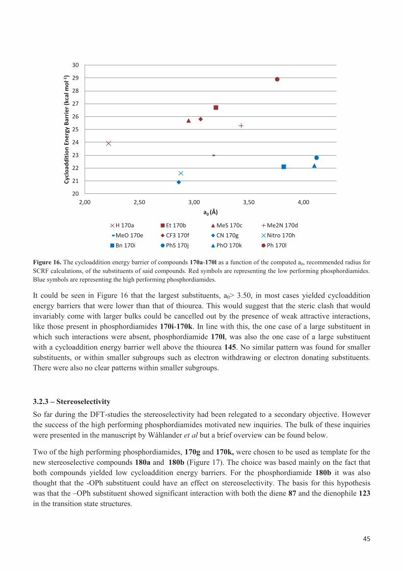
45
Figure 16. The cycloaddition energy barrier of compounds 170a-170l as a function of the computed a0, recommended radius for SCRF calculations, of the substituents of said compounds. Red symbols are representing the low performing phosphordiamides. Blue symbols are representing the high performing phosphordiamides.
It could be seen in Figure 16 that the largest substituents, a0> 3.50, in most cases yielded cycloaddition energy barriers that were lower than that of thiourea. This would suggest that the steric clash that would invariably come with larger bulks could be cancelled out by the presence of weak attractive interactions, like those present in phosphordiamides 170i-170k. In line with this, the one case of a large substituent in which such interactions were absent, phosphordiamide 170l, was also the one case of a large substituent with a cycloaddition energy barrier well above the thiourea 145. No similar pattern was found for smaller substituents, or within smaller subgroups such as electron withdrawing or electron donating substituents. There were also no clear patterns within smaller subgroups.
3.2.3 – Stereoselectivity So far during the DFT-studies the stereoselectivity had been relegated to a secondary objective. However the success of the high performing phosphordiamides motivated new inquiries. The bulk of these inquiries were presented in the manuscript by Wåhlander et al but a brief overview can be found below.
Two of the high performing phosphordiamides, 170g and 170k, were chosen to be used as template for the new stereoselective compounds 180a and 180b (Figure 17). The choice was based mainly on the fact that both compounds yielded low cycloaddition energy barriers. For the phosphordiamide 180b it was also thought that the -OPh substituent could have an effect on stereoselectivity. The basis for this hypothesis was that the –OPh substituent showed significant interaction with both the diene 87 and the dienophile 123 in the transition state structures.
20
21
22
23
24
25
26
27
28
29
30
2,00 2,50 3,00 3,50 4,00
Cyclo
addi
tion
Ener
gy B
arrie
r (kc
al m
ol-1
)
a0 (Å)
H 170a Et 170b MeS 170c Me2N 170dMeO 170e CF3 170f CN 170g Nitro 170hBn 170i PhS 170j PhO 170k Ph 170l

46
Figure 17. The two chiral phosphordiamides 180a and 180b, together with their non-chiral counterparts 170g and 170k. The chiral P center was generated by combining one substituted and one un-substituted aniline groups.
Transition states with each of the new phosphordiamides were then found for a number of different conformations (Figure 18). For the phosphordiamide 180a, 16 different conformations were used each being a combination of cis/trans, dienophile orientation I/II, endo/exo and attack I/II. The phosphordiamide 180b on the other hand was restricted by the C-H…π interaction between the dienophile and the PhO-substituent. Thus only eight conformations in combinations of Cis/Trans, Endo/Exo and Attack I/Attack II were used.
Figure 18. Elements of conformations of the transition state complexes. Each conformation was a combination of three, phosphordiamide 180b, or four, phosphordiamide 180a, different elements.

47
After the transition state for each conformation was found the cycloaddition energy barriers of each conformation was compared. The lowest energy conformation and the lowest energy conformation producing the opposite enantiomer were found and the difference in energy between these two states was used to compute an enantiomeric excess using Eyrings equation (Table 2).
Table 2. Results from the stereoselective analysis.
Most favorable structure Most favorable structure forming the second enantiomer Catalys
t %ee Cis-
Trans Endo/exo
I-II
Attack R-S ΔG‡ (Kcal/mol)
Cis-Trans
Endo/exo
I-II
Attack R-S Energy diff. (Kcal/mol)
180a 46% Cis endo I II R 22.0 Cis endo II I S 0.6 180b 89 % Trans endo - II R 21.2 Trans endo - I S 1.6
The results were impressive in the regard that the very simple Diels-Alder system of the compounds 123 and 87 still produced significant enantiomeric excess even with rather simple catalysts. The 89% ee obtained with phosphordiamide 180b was the more impressive result but the 46% of phosphordiamide 180a was still significant. In addition, the cycloaddition energy barriers were still well below the reference compound thiourea 145 for both chiral phosphordiamides.
A study of the structure of the preferred, lowest in energy, transition states of phosphordiamide 180b revealed a significant amount of C-H---π bonds between the terminal carbons of the diene 87 and the phenyl group on the OPh-substituent of phosphordiamide 180b (Figure 21 and appendix 1). This was true both for the pro-R, preferred, transition state and the pro-S one. These weak interactions were probably a factor in the orientation of the dienophile relative to the catalyst. Another relevant interaction was the C-H---π interaction between the diene and the phenyl substituents on the nitrogen atoms. These interactions were similarly oriented for both the pro-R and pro-S complexes. However, different phenyl rings were involved. In the lower energy pro-R transition state the unsubstituted phenyl group was involved whereas the higher energy pro-S transition state the meta-CF3-substituted phenyl group was involved. This suggested that the C-H---π interaction was stronger with an unsubstituted phenyl group, which in its turn suggests that these interactions are based on a π(Ph)→σ(CH) donation. Overall phosphordiamide 180b was a very interesting candidate as a Diels-Alder catalyst.
The enantioselectivity of the phosphordiamide 180a was, as previously stated, more modest than the one for phosphoramide 180b but it was still significant. This, together with the fact that it still showed an activity significantly above thiourea 145, made phosphordiamide 180a into an interesting catalyst as well. It could thus be stated that there was some promise to the idea of an enantioselective phosphordiamide.

48
Figure 19. Pro-S and pro-R transition states of the phosphordiamides 180a and 180b.
3.3 – Summary and conclusions
The most important discover was that there seemed as if several of the designed phosphordiamides possessed catalytic ability well above Schreiner’s thiourea 145. This was true in particular for phosphordiamides 170g, 170h, 170i, 170k and 170m. Some of them also showed promise as potential stereoselective catalysts with the phosphordiamide, in particular phosphordiamide 180b. It should also be stressed that the modifications necessary to obtain these phosphordiamides were very minor compared to their non-stereoselective counterparts and that the reaction system, the dienophile 123 and the diene 87, with which they were obtained was very simple. In more general terms it would also seem as if strongly electron-withdrawing substituents often, in two cases out of three, boosted the catalytic effect of symmetric phosphordiamides. The same was also true for substituents with aromatic groups with linkers, though these also could be used to increase the enantioselectivity in non-symmetric phosphordiamides. This gives hope to the idea of a phosphordiamides as a framework for new Diels-Alder catalysts. The details, such as explaining how to make a strong phosphordiamide catalyst, remain more complicated however. Overall there seemed to be a lack of strong correlations between the high performing phosphordiamides and Hammett constants and their derivatives. Some very weak correlations were found but there are neither greatly informative nor particularly strong. The same was true for the volume as well. In the same way there seemed to be no strong correlation between the cycloaddition energy barrier and such classical descriptions like HOMO-LUMO gap and hydrogen bond strength. Nonetheless, the smallest HOMO-LUMO gap and the strongest hydrogen bond both yielded (different) high performing phosphordiamides. A significantly stronger finding was that all of the high performing phosphordiamides except phosphordiamide 170e had at least one weak C-H…π, O or N interaction between the substituent and the diene 87. A smaller number, phosphordiamides 170i-k and 170m, also had a substituent interaction with the dienophile 123. This was in stark contrast to the low performing phosphordiamides where none of the phosphordiamides showed any type of secondary interactions. It therefore seemed as if the most important factor in a high performing phosphordiamide was a substituent with significant possibilities to interact weakly with the diene 87. Presumably the weak interactions help stabilizing the transition states in question and thereby lower the cycloaddition energy barrier. Why the very simple phosphordiamide 170g with its

49
single weak interaction was the best performing phosphordiamide of them all remained an open question. Nonetheless more structures were necessary if the idea in question was to be fully explored. It should however be noted that none of the catalysts were tested in vitro rather than in silico. The in vitro reactions in Chapter 2 were by no means this successful, or successful at all. However, both the test reactions and the catalysts tested were significantly dissimilar to the compounds investigated in Chapter 3. It might for example be so that the presence of the meta-CF3-subsituted phenyl group was more important than we previously suspected.
3.4 – Experimental section
The cycloaddition pathways were determined by means of DFT calculations with the Gaussian09 software package. The meta-GGA M06 functional10 § accounting for dispersion forces was used. Geometries were fully optimized without any geometry or symmetry constraint with the double-ζ 6-31+G* basis set11. Frequencies were also computed at this level of theory with the aim of determining the thermochemistry at T = 293 K (zero-point, thermal and entropy energies) and classifying the stationary points as either minima (all-real frequencies) or transition states (single imaginary frequency). Energies were further refined by means of single-point calculations expanding the basis set to the triple-ζ 6-311+G*12 and introducing the solvent effects of chloroform with the continuum SMD model13. The Gibbs energies reported in the text are relative to a 1M standard state, including both the thermochemistry at the DFT(M06)/6-31+G* level and the solvation effects at the SMD-DFT(M06)/6-311+G* level.
For the enantioselective structures (180a and 180b in Figure 17), different sources of structural flexibility were systematically explored with the aim of finding the lowest-energy geometries (Figure 18). These include the trans and cis isomers of the dienophile 123, the endo and exo approaches of the diene 87, the two diastereotopic faces of the dienophile 123 and the intramolecular orientation of the same relative to the organocatalysts (only relevant in 180a; Figure 17).
The volume was calculated at the DFT(M06)/6-31+G** level using the “Volume” command found in Gaussian. The starting structures were found by starting from the transition state in question and then removing every atom except the ones making up the substituent. The lose bond previously leading to the phosphorous atom was capped using a hydrogen atom. The recommended a0 was used as obtains from the log-file.

50
3.5 - References
1. Hammett, L. P., J. Am. Chem. Soc., 1937, 59 (1), 96-103. 2. (a) Anslyn, E. V., Dougerthy, Dennis A., 8.3 Hammett plots-The most common LFER. A general method for examining changes in charges during a reaction. In Modern Physical Organic Chemistry, First ed.; University Science Books: Sausalit, California, 2006; pp 445-453; (b) Hansch, C.; Leo, A.; Taft, R. W., Chem. Rev., 1991, 91 (2), 165-195. 3. Qiu, Y., J. Phys. Org. Chem., 2015, 28 (5), 370-376. 4. Ramírez-Rave, S.; Morales-Morales, D.; Grévy, J.-M., Inorg. Chim. Acta., 2017, 462, 249-255. 5. Hu, F.; Patel, M.; Luo, F.; Flach, C.; Mendelsohn, R.; Garfunkel, E.; He, H.; Szostak, M., J. Am. Chem. Soc., 2015, 137 (45), 14473-14480. 6. Brown, H. C.; Okamoto, Y., J. Am. Chem. Soc., 1958, 80 (18), 4979-4987. 7. Swain, C. G.; Lupton, E. C., J. Am. Chem. Soc., 1968, 90 (16), 4328-4337. 8. Roberts, J. D.; Moreland, W. T., J. Am. Chem. Soc., 1953, 75 (9), 2167-2173. 9. Wittkopp, A.; Schreiner, P. R., Chem. - Eur. J. , 2003, 9 (2), 407-414. 10. (a) Zhao, Y.; Truhlar, D. G., Theor. Chem. Acc., 2008, 120 (1), 215-241; (b) Zhao, Y.; Truhlar, D. G., Acc. Chem. Res., 2008, 41 (2), 157-167; (c) Mardirossian, N.; Parkhill, J. A.; Head-Gordon, M., Phys. Chem. Chem. Phys., 2011, 13 (43), 19325-19337; (d) Zhao, Y.; Truhlar, D. G., Chem. Phys. Lett., 2011, 502 (1-3), 1-13; (e) Greenwood, J. R.; Calkins, D.; Sullivan, A. P.; Shelley, J. C., J. Comput.-Aided Mol. Des., 2010, 24 (6-7), 591-604. 11. (a) Petersson, G. A.; Bennett, A.; Tensfeldt, T. G.; Al-Laham, M. A.; Shirley, W. A.; Mantzaris, J., J. Chem. Phys., 1988, 89 (4), 2193-2218; (b) Petersson, G. A.; Al-Laham, M. A., J. Chem. Phys., 1991, 94 (9), 6081-6090. 12. (a) McLean, A. D.; Chandler, G. S., J. Chem. Phys., 1980, 72 (10), 5639-5648; (b) Krishnan, R.; Binkley, J. S.; Seeger, R.; Pople, J. A., J. Chem. Phys., 1980, 72 (1), 650-654. 13. Marenich, A. V.; Cramer, C. J.; Truhlar, D. G., J. Phys. Chem. B, 2009, 113 (18), 6378-6396.

51
Chapter 4 – Synthesis directed towards a Decalin Terpenoid
______________________________________________________________________________________
4.1 – Introduction
As was discussed in Chapter 1, the synthesis of a decaline terpenoid was planned with the intention of using a Diels-Alder reaction as a central step. The reasoning behind this was that a Diels-Alder reaction would potentially give the desired stereochemistry in three different carbon atoms in the molecule (Scheme1).
Scheme 1. Retrosynthetic analysis of the Asmarine H. The scheme is a reproduction of Scheme 8 in Chapter 1.
Since the initial plan of using the phosphordiamides as catalysts was not viable, as was discussed in Chapter 2, an alternative plan was devised. The initial plan was then to use a thiourea but, as will be seen further down in this chapter, that plan was soon abandoned as well. This leads to two new concepts in need of explaining. The two concepts are activation of conjugated carbonyl compounds using Lewis acids and imidazolidone catalysts respectively.
4.1.1 - Lewis acid catalyzed Diels-Alder reactions using conjugated carbonyl compounds The first topic to be discussed is the Lewis acid catalysts. In 1960 the first example of a non-hydrogen Lewis acid catalyzing a Diels-Alder reaction was demonstrated using AlCl3 as a Lewis acid and anthracene and malonic anhydride as a diene and dienophile respectively1. A reaction mechanism was proposed as early as 19652 and a few years later a, slightly improved, description of the reaction pathway was found using computational models3. The reaction had a simple mechanism in which a Lewis acid binds to the carbonyl-oxygen of a conjugated carbonyl group (Figure 1). This lead to a lowering of both the HOMO and LUMO of the carbonyl compound3. The lower HOMO and LUMO lead to a lower energy barrier when the conjugated carbonyl-Lewis acid-complex acts as a dienophile and interact with the diene (Figure 1).

52
Figure 1. Lewis acids (LA) effect on conjugated carbonyl compounds in Diels-Alder reactions3.
There are a large number of Lewis acids that have been used in Diels-Alder reactions in the literature. A very small selection of catalysts and reactions are presented in Scheme 2 below. They were selected based on similarities to the proposed starting materials 75 and 76 and their suggested reaction.
Scheme 2. Examples of Lewis acid catalyzed Diels-Alder reactions4.
4.1.2 – Imidazolidinone catalysts
The second important group of catalysts to be discussed are the imidazolidinone catalysts also known as the Macmillan catalysts5 (Figure 2). These catalysts were mentioned shortly in Chapter 1. The mechanism for all reactions in which the Macmillan catalysts were involved was initiated the same way. A carbonyl compound, ketone or aldehyde, formed an iminium (193a), enamine (193b) or SOMO (193c) ion together

53
with the imidazolidinone catalyst. The mechanism would then differ depending on the reaction but the ionic intermediate would facilitate the reaction in question.
Figure 2. The family of Macmillan catalysts and their reactive intermediates when performing a Diels-Alder reaction5. The X for the catalysts 189a, 189b, 190a, 190b and 191 was a generic counter ion such as Cl- or Tf2N-.
The MacMillan catalyst has been used for several different reactions over the years such as α-halogenation6, α-oxidation7, and several sorts of conjugated additions8. Of main interest for the thesis was however the reaction for which the Macmillan catalysts were initially used, the Diels-Alder reaction9. The range within the reaction in question covered everything from hetero-Diels-Alder10 to intermolecular Diels-Alder-reactions11 (Scheme 3).
Scheme 3. Examples of regular Diels-Alder reactions, hetero-Diels-Alder reactions and intermolecular Diels-Alder9-11.
4.2 - Early attempts of Diels-Alder reactions using several different dienes
The initial diene tested was diene 75. The diene was synthesized (Scheme 4) using known procedures. A Morita-Baylis-Hillman like α-iodination12 gave the ketone 202 which in its turn was protected using the disilyl ether 203 and TfOTMS as a catalyst13 to obtain the spiro compound 204. Both of these reactions were performed giving fair yields. The vinylation was performed using a known Stille-reaction14 to receive

54
the diene 75. However in our hands the Stille-reaction was less successful than what was reported in the literature.
Scheme 4. Synthesis of the diene 75.
Initially some attempts were of Diels-Alder synthesis using the diene 75 and the aldehyde 76 using the Macmillan catalyst 11411 and the thiourea 13515 (Figure 3 and Scheme 5). Both of these compounds were chosen as well known catalysts for chiral Diels-Alder reactions. The attempts did however not yield any reaction at all (entries 1-4, Table 1). Therefore a, significantly stronger, Lewis acid, BF3•OMe2
4c, 16, was attempted instead. These attempts yielded a much more complicated mixture which however did not contain the desired product 74. An attempt to cool down the reaction and use one tenth of the amounts of BF3•OMe2 revealed that the Lewis acid seemed to deprotect the diene. The diene 75 was therefore abandoned.
Figure 3. Catalysts used to attempt
Scheme 5: General scheme for test reactions using the diene 14 and the aldehyde 13, see also Table 1.
Table 1: Overview of attempts at cyclization of the diene 75 with the aldehyde 76.
Entry Aldehyde (equius.) Solvent Catalyst Time (h) Temp (oC) Product found 1 1.2 MeCN 20% 114 5 days -20 No 2 1.0 MeCN 20% 114 18 25 No 3 1.0 DMF 20% 114 8 days rt No 4 1.5 Hexane 15% 135 7 days rt – 35 No 5 2.5 CH2Cl2 200 % BF3•OMe2 3 -78 Nob 6 2.5 CH2Cl2 20 % BF3• OMe2 7 -78 Noa
aFound loss of protecting group in crude product. bCrude product was a very complicated mixture.

55
A new diene 208 was synthesized (Scheme 6). This time by first reducing the ketone 202 to the alcohol using NaBH4
12. After that a benzylation was performed on the alcohol 206 with tert-n-Butylammonium iodide as a catalyst17 to obtain the benzyl ether 207. Finally the benzyl ether 207 was vinylated using a Kumada reaction18, picked to avoid the tin from the previous Stille reaction, to obtain the diene 208. Once again the coupling reaction was less successful, with quite complicated crude products, but the other reactions produced fair yields.
Scheme 6. Synthesis of the diene 39.
New attempts at a Diels-Alder reaction, this time using the diene 208 rather than the diene 75, were made using BF3•Et2O as a catalyst. These reactions did once again yield very complicated crude products with very small amounts of anything that could even potentially be the desired product 209 (Scheme 7).
In order to avoid further instability of the diene 208 a whole battery of stability tests were performed. In the tests the diene 208 was mixed with ZnCl2
4a, 19, ZnBr220, Al(CH3)3
21 and the oxazaborolidine 21022 in the solvents associated with the respective catalysts in the literature at appropriate dilutions. The catalysts were chosen based on available catalysts that were available at our labs. From the stability tests it was seen that the diene 208 seemed stable with Al(CH3), oxazaborolidine 210 (Figure 4) and ZnCl2.
Figure 4. The oxazaborolidine 210.
Test reactions were performed using these catalysts, the diene 208 and the aldehyde 76 (Table2). In the majority of these tests very little happened at all. Al(CH3)3 seemed to react with the aldehyde forming an alcohol rather than catalyzing a reaction. The oxazaborolidine 210 did not seem to react at all. Finally, ZnCl2 showed no reaction when in Et2O but did show a reaction in CH2Cl2 and (CH2Cl)2. The later reactions did however once again cause a very complicated mixture producing what seemed to be a multitude of products. After flash a little (less than 5%) of a compound that seemed to be a possible match for the desired compound. The structure seen in Figure 5 shows the 1H-spectra of said fractions. The 1H-NMR, 13C-NMR and Mass spectra all strongly indicate that the compound presented is the desired compound 209.

56
Scheme 7. General scheme for reaction of the aldehyde 76 with the diene 208 and a Lewis acid, see also Table 2.
Table 2. Overview of attempted reactions of the aldehyde 76 with the diene 208 using selected Lewis acids.
Entry 76 (equius)
Solvent Temp Time Lewis acid
1 5 Et2O rt 2 days 1 eq. ZnCl2 2 5 CH2Cl2 rt 4 days 1 eq. ZnCl2 3 7 (CH2Cl)2 40 oC 17h 5 eq. ZnCl2 4 5 7:3 (CH2Cl)2:PhMe rt 2 days 6 eq. AlMe3 5 1 (CH2Cl)2 0 oC 1.5 days 0.40 eq. 210
Once again the reactants did not seem to lead to simple reactions. Debris indicated that the protecting group, that is the benzyl group, had once again been lost during the reaction. Another protecting group was therefore seen as necessary.
Figure 5. A reasonable assignment of shifts given 1H-NMR spectra obtained. The spectrum was obtained from entry 3 in Table 2.
4.3 - Attempted synthesis of the Diels-Alder adducts 215 and 219a and b using the diene 212
A common theme for both previous dienes 75 and 208 had been that they seemed to lose their protecting group when mixed with Lewis acids. This was seen as a possible starting point for the formation of all the complicated mixtures seen above. A search through the standard work of Greene's Protective Groups in Organic Synthesis23 revealed that the TBDPS-group was among the most stable protecting groups that could be found with regard to Lewis acids. Thus the diene 212 was designed.

57
4.3.1 - Synthesis of the third diene 212 The silylation of the alcohol 206 was based on literature procedures24 with very good results. The Negishi coupling reaction, this time picked to try something milder than the Kumada reaction, also gave a good yield of the desired diene 212 (Scheme 8).
Scheme 8. Synthesis of the third diene 212.
The coupling reaction used a different type of catalyst compared to previously. In the early attempts with Negishi couplings and all the previous Kumada reactions, Pd(PPh3)4 was used. This change in catalyst was brought on by formation of significant amounts of the alkene 213 that was difficult to separate from the desired product 212. The catalyst Pd(dppf)Cl2 is supposed to help with β-hydride elimination25 and the alkene 213 does indeed look like a product of β-hydride elimination. However, to the author’s knowledge β-hydride elimination is not known to occur in alkenes, which means that given no further evidence it would be rash to claim that β-hydride elimination was the cause of the problem. What could be stated however was that the change of catalyst solved the problem, since the alkene 212 was never found in the crude product after the change of catalyst.
4.3.2 - Diels-Alder reaction with the diene 212
4.3.2.1 - Diels-Alder Reactions using the aldehyde 76 as a dienophile
Previous experiences of instability of the dienes 75 and 208 with Lewis acids were discouraging. Therefore a number of stability evaluations were performed on the diene 212 using the previously tested Lewis acids, and a few more that had been found. In these cases, the 1H-NMR signal of a lost protecting group was significantly differentiated from that of the diene 212 in a crude product 1H-NMR, therefore a comparison between the diene 212 and the free silanol 214 was set up (Scheme 9 and Table 3).
Scheme 9. General reaction for stability tests of 212.

58
Table 3. Overview of stability of 212.
Entry Catalyst Solvent Temp. (oC) Time (h) 214/212a
1b 50% AlCl3 C6H5CH3 rt 23 4/1 2b 300% ZnCl2 (CH2Cl)2 rt 19 1/0 3 50%ZnCl2 (CH2Cl)2 rt 20 1/0 4 50%ZnBr2 (CH2Cl)2 rt 20 0.94/1 5 50%ZnCl2 (CH2Cl)2 0 20 0.32/1 6 20%ZnBr2 (CH2Cl)2 0 20 0.23/1 7 20% AlCl3 (CH2Cl)2 0 20 3.47/1 8 50% MgBr2
c (CH2Cl)2 rt 21 0/1 9 40% Zn(TFA)2 (CH2Cl)2 rt 21 1/0 10 100% EtAlCl2 (CH2Cl)2 -78 to -20 21 1/0 11 100% AlMe3 (CH2Cl)2 0 21 0.78/1
aThe ratio between tert-butyl diphenyl silyl alcohol 214 and the diene 212 measured in 1H-NMR. bMixture of the diene 212 and alkene 213 were used as starting material. Percent Lewis acid based on the amount of the diene 212. c Catalyst did not dissolve.
As could be seen the stability of the diene 212 once again was far from perfect. The only completely stable system was the one shown in entry 8, but others also significantly improved their stability when one lowered the temperature (compare entries 3 and 5). Three small test reactions were set up based on entries 5 and 6 to test the ZnBr2 and ZnCl2 (see Table 4 and Scheme 10).
Scheme 10. General scheme for the reaction between 76 and 212 seen in Table 7.
Table 4. Overview of attempted reactions between the aldehyde 76 and the diene 212 with Lewis acids.
Time (h) Temp. Catalyst. 212/214/215a
1 25 0 - 10 oC 33%+33%b ZnCl2 74/26/0 2 20 0 oC 50% ZnBr2 34/55/11 3 47 0 oC 100% ZnBr2 5/88/7
aThe 1H-NMR of the crude product showed that some kind of product that was not the aldehyde 76 was present in small amounts. The integral of all the new aldehyde peaks combined was compared to the starting material 212 and fragment 214 as in table 6. bStarted reaction with 33% catalyst and then added 33% more after 18 h.
The reaction with ZnCl2 (entry 1, Table 4) was initially started at a lower percentage of catalyst, that was later increased when no product was visible on TLC after one night. Based on the experience from the reaction described in entry 1, it was decided that ZnBr2 would be tested with a larger amount of catalyst immediately. In the crude product of entry 2, mass spectrometry revealed that a mass matching the mass of the compound 215 could be found. A few peaks in the 1H-NMR of the crude product was thought to be possible matches for 214 and the results seen in Table 4 therefore includes the integral of this peak compared to the peaks of the diene 212 and the silanol 214. Given that entry 2 was performed on a very small scale, flash chromatography was not possible, at least given that reported peaks were far from the only thing seen in the crude product. A higher percentage catalytic reaction was prepared as entry 3 to try and see if more ZnBr2 and more time could give a crude product mainly containing the potential adduct 215. As can be seen in Table 4 this was not the result that was received.

59
4.3.2.2 - Diels-Alder reaction using the oxazolidinone 218 as dienophile
A new approach was once again deemed necessary. Since a large amount of effort had been spent on the diene the focus was now shifted to the dienophile 76. An article that was found suggested that the aldehyde 76 in combination with the Lewis acids used so far in the investigation would not give the desired isomers of the Diels-Alder adduct 21526. Instead the article proposed that one should use the oxazolidinone 218 as a dienophile with an auxiliary that would guide the diene and dienophile into the desired conformation. This type of strategy has been utilized for similar Diels-Alder reactions26-27.
Scheme 11. Synthesis of the new dienophile 218.
A literature procedure28 produced the oxazolidinone 218 in two steps at good yield by first turning the acid 216 into an acid chloride and the react the acid chloride with a deprotonated 217 as seen in Scheme 11. The reaction got a minor change in reaction time, for practical reasons, but otherwise worked fine. The dienophile 218 was put to use in reactions with the diene 212 with clearly better results than previously (Table 5).
Scheme 12. Diels-Alder reaction to form the adducts 219a (±) and 219b (±).
Figure 6. Other recognizable byproducts found in 1H-NMR of the crude product of Diels-Alder reactions listed in Table 5.

60
Table 5. The development of a successful method for synthesis of the Diels-Alder adduct 219a (±) and 219b (±).
Entry Scale (mg)
Eq. 218
Lewis acids Eq. Lewis acid
Temp. (oC)
Time (days)
Gas Ratio 212: 219a: 219b: 214
in crude product 1H-NMR
Yield Isomers 219a:219b
1 20 1 Me2AlCl 1.9 0 5 N2 57:7:7:29 - 2 20 1 EtAlCl2 1.9 0 6 N2 81:7a:0:12 - 3 20 2 EtAlCl2 1.9 rt 3 N2 60:11:7:22 - 4c 60 0.7 EtAlCl2 0.63 rt 5 N2 46:26:15:13 15% (1:0) 5 20 6 EtAlCl2 5.7 rt 19h N2 3:49:27:21 - 6 20 4 EtAlCl2 3,8 rt 20 h N2 11:44:17:28 - 7 100 4 EtAlCl2 3.8 rt 20h N2 41:39:15:5 24% : 8% 8 100 4 EtAlCl2 3.8 rt 24h N2 6:55:31:8 38 % Combined (5:3) 9 100 4 EtAlCl2 3.8 0 oC 48 h N2 55:9:5:31 -
10 100 4 EtAlCl2 3.8 Reflux 9 h N2 23:47:10:20 27% Combined (4:1) 11 100 4 EtAlCl2 3.8 rt 24h N2 40:40:7:13 27% 12 100 4 EtAlCl2 3.8 rt 24h Ar 30:44:25:1 26%:23% 13 100 4 EtAlCl2 3.8 rt 50 h Ar 19:51:26:4 35%:18% 14 300 4 EtAlCl2 3.8 rt 49 h Ar 12:56:27:5 55% Combined (9:5) 15 232 4 EtAlCl2 3.8 rt 51 h Ar 4:56:30:10 56 % Combined (3:2) 16 1189 4 EtAlCl2 3.8 rt 51 h Ar 9:52:7:32 40% (1:0) 17 502 4 EtAlCl2 3.8 rt 51 h Ar 15:58:27:0 38%:26% 18 1390 4 EtAlCl2 3.8 rt 51 h Ar 16:55:29:0 66%d Combined (4:3)
aA product with the same shift as the desired product 64a but with a different shaped peak. cThe conversion is better understood when comparing to the conversion of the dienophile 218. This gave the ratio 218:219a:219b 26:48:26 . dOnly one flash, no separation of isomers.
Initially the reaction was attempted as described in the literature26 (entry 1, Table 5) and while the result was rather unimpressive this marked one of the first times that a substantial amount of the diene 212 seemed to survive for a long period of time (multiple days) in the reaction mixture. The alternative catalyst EtAlCl2 (entry 2) seemed to remove even less of the protecting group so further experiments were performed with this compound. After significant testing 4 equivalents of the oxazolidinone 218 together with 3.8 equivalents of EtAlCl2 with temperatures rising to ambient temperature (compare entry 6 to entries 3-5, 9 and 10) was agreed on to be the best conditions. The reaction could however be unpredictable (compare entries 7 and 8), and is rather sensitive to its initial temperature. The decision to switch to argon from nitrogen as a covering gas helped with this unpredictability. The scaling up of the reaction was also a problem and it was discovered that the reaction was more sensitive than most reactions with regards to starting temperature. Therefore longer time in the dry ice bath was necessary in order to get results that were as good as or even better than in the small scale (see entries 15 and 16). Another regard was the considerable problems with the systems for purification by flash chromatography. A lot of different systems for flash chromatography were tried which might explain part of the variation in final yields compared to the expected product. In most cases a second flash chromatography to separate the isomers 219a (±) and 219b (±) was necessary but that in itself did not seem to matter significantly (compare entries 17 and 18).
Why the Diels-Alder reaction seems to work better with the oxazolidinone 218 than using the aldehyde 76 was an open question. Though the ZnBr2 and ZnCl2 of earlier was never been tried with this particular reaction it was rather noticeable that a Lewis acid that tore the molecule to pieces (EtAlCl2, entry 10 in Table 6) still retained significant amounts of the diene 212 when mixed with the oxazolidinone 218. This was in stark contrast to when the same molecule 212 was mixed with ZnBr2 and the aldehyde 76 which resulted in complicated crude products and a lot of loss of protecting group and very little compound desired compound. One possibility was that the oxazolidinone 218 provided a better site for the Lewis acid

61
to bind to. A Lewis acid placed on an oxazolidinone would form a significantly stronger bond than a Lewis acid on an aldehyde, since the oxazolidinone has got two Lewis bases that the acid could interact with. Another difference was that the oxazolidinone 218 was mixed with EtAlCl2 at a low temperature before the diene was added and the reaction took place whereas the aldehyde 76 was usually mixed with the dienes at a low or semi low temperature and had the Lewis acid slowly added to it. Given that there were some scale up problems one could postulate that the low temperature was not just a means to control excess energy from complexation of the Lewis acid with the oxazolidinone 218. A possible reason for such a requirement would have been if the Lewis acid needed time and low temperatures to complex irreversibly with the oxazolidinone 218. Once complexed with the oxazolidinone 218 the Lewis acid would be reluctant to dissociate even at higher temperatures (see Figure 7). This would have prevented the Lewis acid from interacting in a nonconstructive way with the diene 218 and also aiding in catalyzing the desired reaction. A similar “pre-reaction phase” for the aldehydes might have given a more positive result earlier. That said, it should be noted that the amount of the aldehyde 76 in comparison to the amount of Lewis acid in many test reactions were significantly larger. Therefore one would still expect these aldehydes to complex with the Lewis acids rather quickly.
Figure 7. The dienophile 218 complexing with EtAlCl2 irreversibly.
4.3.2.3 – Structural elucidation and explanation of the Diels-Alder adducts 219a (±) and 219b (±)
Mass spectrometry of the purified isomers gave a molecular ion mass that was consistent with a Diels-Alder adduct for both compounds 219a (±) and 219b (±). As could be seen in Figures 8 and 9 there were sixteen different directions in which the diene can approach the dienophile with the resulting eight different isomers.

62
Figure 8. The first four of the eight possible transition states from the Diels-Alder reaction together with their respective products. The compounds within the square were the ones found in the reaction.

63
Figure 9. The final four of the eight possible transition states from the Diels-Alder reaction together with their respective products.
Deciding which compounds that had been obtained was no small task but COSY and NOESY 2D-NMR gave good answers. Initially the regioselectivity of the dienophile was decided. This was done using COSY-NMR. A good start was the COSY-spectrum for 219a (±) seen in Figure 10. The doublet at ~0.9 ppm was identified as the methyl-2 group on the dienophile since the splitting indicates that it, unlike the other methyl group, had got a hydrogen atom on the adjacent carbon. Using the COSY one could identify the hydrogen signal of the adjacent hydrogen following the black arrows. Apart from the methyl group the new hydrogen correlated to two other hydrogen signals that integrated for one hydrogen each with the blue arrows pointing exactly in-between them. This in itself proved that the compound could not be 222a-b (±) or 223a-b (±) since these compounds would only have coupling to one hydrogen atom. The insight was confirmed when further correlation was found between the previously identified hydrogen atoms and the alkene atom at ~6.0 ppm (as seen by the magenta colored arrow). The COSY-walk is illustrated in Figure 11.

64
Figure 10. COSY-spectrum of the adduct 219a (±). The COSY-spectrum is expanded in such a way that the phenyl hydrogen signals are not visible.
Figure 11. COSY walk seen in Figure 10 illustrated.
For 219b(±) a different spectrum (Figure 12) was obtained but the reasoning is analogous to the one for 219a (±).

65
Figure 12. COSY of the adduct 219b (±). The COSY is magnified in such a way that phenyl hydrogens are not visible.
NOESY-NMR was necessary in order to determine the stereochemistry any further. The discussion of the NOESY-NMR will be very confusing unless a there is a systematic system for referring to the hydrogen atoms and their 1H-NMR signals. Such a numbering system is therefore presented in Figure 13.
Figure 13. Numbering of the carbons in the decaline system.
The first compound to be identified was 219a (±). Studying the previously mentioned 2-H one could see that it correlation with methyl-2 (green ellipse, Figure 14), the 8a-H (orange ellipse, Figure 14) and one but not both of the 3-H atoms (purple ellipse, Figure 14).The non-phaseable peaks between 1.0 and 1.5 ppm were disregarded. With that in mind one could also study the methyl-2 peak in Figure 15. Here the correlation was found between the methyl-1 (blue ellipse, Figure 15), the 2-H (red ellipse, Figure 15) and both 3-H atoms (purple and pink ellipses, Figure 15).

66
Figure 14. 1D-NOESY of 219a (±) illuminating the 2-H peak at 3.02 ppm.
Figure 15. 1D-NOESY of 219a (±) illuminating the methyl-2 peak at 0.88 ppm.
The fact that methyl-1 and the methyl-2 showed a correlation indicated that the methyl groups were on the same side of the ring. Two possible configurations of the carbons 1, 2 and 3 in the A-ring were available from that information; one where the oxazolidinone group was in the endo-position and one where it was in the exo-position (Figure 16). Further support were found in the fact that 2-H only correlated to the methyl-2 and one of the 3-H which indicated that the hydrogen atoms was placed in a conformation such that the 2-H was as far as possible from the methyl-1 group but also as far away as possible from one of the 3-H group. With those points in mind the exo-configuration in Figure 16 seemed more reasonable.

67
Figure 16. The two possible stereo configurations of the carbons 1-3.
To further strengthen the case of the exo-configuration the 8a-H (Figure 13 and 18) was studied. From Figure 18 it was clear that the 8a-H atom (orange ellipse) had got a correlation to the 2-H (red ellipse) but not to anything else on the A-ring. The brown ellipse represented the 5-H hydrogen atom and was of use later to decide the position of the TBDPS-group. This once again supported the exo-configuration over the endo-configuration since it was unlikely that 8a-H in an endo-configuration would have a correlation to 2-H but not to either of the methyl groups at carbons 1 or 2 (Figure 17).
Figure 17. Further expanded stereoconfigurations of carbons on the A-ring.
Further confirmation of the stereochemistry presented came from one of the 3-H atoms (pink ellipse) in Figure 19. There correlations between both methyl groups (green and blue ellipses) were found but no correlation to 2-H was visible. This indicated that the pink 3-H was axial and at the opposite side of the ring compared to 2-H which was also axial. A final indication of the pink 3-H being axial was found in Figure 20 where the correlations of 4-H (yellow ring, the alkene hydrogen) could be seen. The signal of one of the 3-H atoms (the pink and purple ellipses) also was significantly weaker (pink ellipse) than the other (purple ellipse). This was once again indicative of the fact that the pink ellipse 3-H was an axial proton since 4-H was equatorial per definition and two equatorial hydrogen atoms on adjacent carbons were placed closer to each other than an equatorial and an axial hydrogen atom were. With this the conformation of the A-ring seemed reasonably set and that conformation was strongly indicated to be the exo-conformation (Figures 16 and 17).

68
Figure 18. 1D-NOESY of 219a (±) illuminating the 8a-H peak at 3.15 ppm.
Figure 19. 1D-NOESY of 219a (±) illuminating a 3-H peak at 1.81 ppm.

69
Figure 20. 1D-NOESY of 219a (±) illuminating a 4-H peak at 6.05 ppm.
For the configuration of the carbon 5 (Figure 13), a study of the hydrogen atom 5-H was necessary. In Figure 21 the hydrogen atom 5-H showed clear correlations to the 8a-H hydrogen atom (orange ellipse) and weakly to the 4-H hydrogen atom (yellow ellipse). An unmarked peak close to 1.5 ppm could also be seen. This was a hydrogen atom from the B-ring and more precisely one of the 6-H hydrogen atoms (confirmed by COSY-NMR). From a combination of the information available in the B-ring and in the A-ring the position of the 5-H hydrogen atom at the same side of the molecule as the 8a-H hydrogen atom was deduced. The remaining question was then whether the atom 5-H was axial or equatorial. As previously stated it could be seen in Figure 20 that the 5-H hydrogen atom only correlated with one of the 6-H hydrogen atoms and correlated very weakly with the 4-H atom. Therefore an endo-position 5-H seemed more likely than in an exo-position one as illustrated in Figure 21. One would have expected an exo-position 5-H to correlate to both correlate to both 6-H hydrogen atoms but not to the 8a-H hydrogen atom. All the previously presented facts strongly indicated that the compound 219a (±) had the structure presented in Figure 8.

70
Figure 21. 1D-NOESY of 219a (±) illuminating a 5-H peak at 4.17 ppm.
Figure 22. Expected correlations between two conformers of 219a (±).
For the compound 219b (±) the structure clarification was rather similar (Figure 23). Once again there was a correlation between the red ellipse 2-H hydrogen atom and both the methyl-2 (green ellipse, Figure 22) and one of the two 3-H hydrogen atoms (purple ellipse, Figure 22). There was also a correlation to the 8a-H hydrogen atom (orange ellipse, Figure 23). As with 219a (±), it could be inferred from this that the 2-H hydrogen atom and the 8a-H atoms were both placed on the same side of the ring. The fact that there was only correlation between the methyl-2 hydrogen atoms and one of the 3-H atoms, and not the methyl-1 atoms or both 3-H atoms, was indicative of the 2-H being in an axial position which in its turn was indicative of the oxazolidinone side chain being in an exo or equatorial position as was discussed for the compound 219a (±).

71
Figure 23. NOESY NMR for the compound 219b (±). Please note that the phasing is performed in such a way that it is optimized for the peaks between 3.0 ppm and 5.0 ppm.
A rephrased and zoomed in part of the upper quadrant between 0.5 and 2.3 ppm also revealed great similarities to 219a (±) (Figure 24). The most important insight was that the methyl groups on carbons 1 (blue ellipse, Figure 24) and 2 (green ellipse, Figure 24) once again correlated and thus were situated on the same side of the ring. The fact is that the 3-H atoms (pink ellipse and purple ellipse, Figure 24) once again showed the pattern of one of them having a correlation only with methyl-2 (green ellipse, Figure 24), while the other seemed to correlating to both methyl groups (blue ellipse and green ellipse, Figure 24). When this knowledge was combined with the previous knowledge of the compound, the result for the A-ring became something very similar to ones for compound 219a (±). Thus the oxazolidinone group was likely placed in an exo position (equatorial), the methyl groups were on the same side of the ring and both the 2-H and 8a-H atoms were in an axial position.

72
Figure 24 NOESY NMR for the compound 219b (±). Please note that the phasing is performed in such a way that it is optimized for the peaks between 0.5 ppm and 2.3 ppm.
The next question was therefore how the compounds 219a (±) and 219b (±) differ. The most obvious starting point for this enquiry was the 5-H hydrogen (brown ellipse, Figure 25) since that is one of the few variable places left in the molecule. It was found that, unlike for the previous hydrogen atoms, the correlations differed in the case of 5-H (brown ellipse, Figure 25). The first difference was that there did not seem to be a correlation between the 5-H hydrogen atom (brown ellipse) and the 8a-H atom (orange ellipse) which has been seen before (Figure 18). The 5-H hydrogen atom did have a correlation to the 4-H atom (yellow ellipse) as expected but it did not have correlations to one but rather two B-ring hydrogens. The fact that a correlation between the 5-H and the 8a-H atoms could not be found was indicative that the 5-H and 8a-H atoms were on different sides of the B-ring (the 6-H atoms, black ring). The presence of two rather than one B-ring protons was also interesting, since that would indicate an equatorial rather than an axial position for the 5-H hydrogen atom as was demonstrated in Figure 15.

73
Figure 25. NOESY NMR for the compound 219b (±). Please note that the phasing is performed in such a way that it is optimized for the peaks between 3.0 ppm and 5.5 ppm.
With the evidence given it was considered reasonable that the only difference between 219a (±) and 219b (±) was to be found in the position of the TBDPS-group. From the presented results it seemed reasonable that the circled structures in Figure 8 were the compounds formed.
To explain the selectivity for the compounds 219a (±) and 219b (±) in the Diels-Alder reaction, the transition states seen in Figure 8 and 9 have to be considered. Initially the regioselectivity was considered29. Well-known regioselective Diels-Alder theory stated that the exocyclic carbonyl group in the dienophile 218 would have acted as an acceptor group. The acceptor group would in its turn have lowered the LUMO-energy of the dienophile 21829b. The LUMO was also polarized towards the marked carbon in Figure 2829b,
30. This polarization would increase even more with the use of a Lewis acid30. For the diene 212 and its HOMO-orbital the case was not as clear. However, the most reasonable explanation for the results received was that both the methylene groups binding to the π-system were donators and as a rule would therefore raise both energy of the HOMO and polarized the HOMO towards the unsubstituted carbon circled in Figure 2629b, 30. The explanation of this is less straight forward. A carbon-substituent in the 3-position of the diene, marked by an “a” in Figure 26, would polarize the HOMO of the diene towards the terminal vinyl carbon, marked “c” in Figure 2630. The carbon binding to the 2-position, marked “b”, will have a negative impact on the described polarization, however it will be less so then the one binding to the 3-position30. The regioselectivity theory stated that the point with a high LUMO-coefficient, the carbon towards which the LUMO was polarized, would couple with the carbon with a high HOMO polarization as seen in Figure 2629-30. It could therefore be deduced that the reaction was expected to have a preference for the compounds 219a-b (±) (and 221a-b (±)) which fitted well with the fact that neither 222a-b (±) (nor 223a-b (±)) were found in the reaction.

74
Figure 26. Illustration of the dienophile orientation selectivity.
4.4 - Further work on the diene 212
After the isomers 219a (±) and 219b (±) had been synthesized it was noted that two more steps would bring the compound up to the closest equivalent to the ketone 73 seen in Scheme 8 in Chapter 1 (replicated in Figure 27 below).
Figure 27. A replication of part of the Scheme 1 at the introduction to Chapter 4 and earlier in Chapter 1. An initial example of a retro-synthesis scheme for the decaline structure.
The products 219a-b (±) were analogue to the compound 74 with a change in protection group and an oxazolidinone group instead of an aldehyde group. Since it was thought that the oxazolidinone would be a stable group, especially compared to an aldehyde, it was thought that a simple deprotection followed by an oxidation of the deprotected alcohol would be possible. The two planned steps were presented in Scheme 13.

75
Scheme 13. Planned steps to continue with 219a (±) after the successful Diels-Alder reaction.
However this plan fell on the fact that the first reaction, deprotection with TBAF, was a failure. Exactly what was causing the problem was unclear but the 1H-NMR of the resulting crude product contained no trace of the oxazolidinone side chain. It was therefore decided that a few more steps were necessary and the reaction shown in Scheme 14 was instead pursued.
Scheme 14. Synthesis of the Diels-Alder adduct 219a (±) to the ketone 230 (±).
The initial reduction step31 resulted in significantly lower yield than expected due to the formation of the second product 227a (±). This problem was rare but not completely unheard of in the literature and no change in conditions really received in an improvement in ratio32. The benzylation step proceeded decently and so did the deprotection step, even if both a large amount of TBAF and a long reaction time was necessary in the latter case. In the final step it was discovered that the Dess-Martin reaction (using Dess-Martin periodinane, DMP) actually gave an esterified side product 231 (±) (not isolated pure but confirmed with MS and HMBC) when an excess of DMP was used. Using the bare minimum did however give the good yield of 87%.

76
Scheme 15. The first three steps of the synthesis seen in Scheme 20 using a mixture of 219a (±) and 219b (±).
In theory both the isomers 219a (±) and 219b (±) could lead to the ketone 230 (±) performing the same reactions as seen in Scheme 14. So with the success of the reactions in Scheme 14 a similar scheme using a mixture of the two isomers 219a (±) and 219b (±) was undertaken and presented in Scheme 15. Already in the reduction step it was made clear that the reactivity of the isomers were not really similar. The isomer 219b (±) was significantly less reactive than the isomer 219a (±), or rather it turned out to be significantly more prone to form 227b (±) than 219a (±) formed 227a (±). In the benzylation step there were strong indications of the b-isomer reacting slower than the a-isomer. These indications lead to a second addition of benzyl bromide being added earlier than in the reaction with only the a-isomer. The result of the early addition was that the reaction times of the reaction with the isomer mixture ended up very similar to the on with only the a-isomer. The benzylation step and the deprotection step got their yield calculated together since the purified mixture of the benzylation step also contained 5% dibenzyl ether. The deprotection step however gave a surprising result. The a-isomer behaved as before but the b-isomer did not seem to react at all. After separating the compounds after the deprotection a bit of pure benzyl ether 228b (±) was obtained. The numbers in scheme 21 show the yield as a total yield from the combined amount of the alcohol isomers 226a and b (±). A more precise measurement of the yield of the alcohol 229a (±) from the alcohol 226a (±) would be 63%. The same yield of the benzyl ether 228b (±) from the alcohol 226b (±) would be 71%. A second attempt of deprotecting was made using a different, decidedly dryer33, fluoride source. This once again yielded the same negative result as can be seen in Scheme 16.
Scheme 16. Second attempt at cleavage of the silyl ether in the compound 228b (±).

77
As previously stated the isomers 228a (±) and 228b (±) would react differently in the deprotection step. This was somewhat surprising and necessitated some further study. The structures of the isomers 228a (+) and 228b (+) were optimized using DFT methods (Figure 28). It seemed as if the axial conformation of the isomer 228b (+) had a stabilizing π---π interaction (blue circle, Figure 30). The strength of a π-stacking has been estimated to around 2.7 kcal/mol34 which would mean that if the compound in question formed such a bond it would likely lead to a stable conformation. It should also be noted that attempts to optimize the isomer 228b (+) in a conformation similar to the one of isomer 228a (+) (Figure 28), with the tert-butyl group facing the double bond, resulted in a conformation that was roughly 3.0 kcal/mol higher. This was however not true “vice versa”. The isomer 228a (+) did not decrease in energy when arranged in a similar conformation as the one seen for the isomer 228b (+), but rather resulted in a conformer with an insignificantly higher energy (around 0.06 kcal/mol). This discrepancy could best be explained by the different orientation of the oxygen atom binding to the silicon atom. The resulting angle of the phenyl groups can in this conformation not align properly with the diene. Further explanation to the difference in reactivity was found by examining the energy surface of the reaction. This was, of course, once again performed using DFT and using the optimized structures of the isomers 228a (+) and 228b (+) as starting points.
Figure 28. The two initial structures 228a (+) and 228b (+). Selected weak interactions are highlighted using a colored circle (blue). Color core: green (F), grey (C), white (H), red (O) and blue-grey (Si).
The results of this examination of the energy surface can be found in Figure 29. The results are presented with the enthalpy change in each step. The entropy turned out to be more difficult to model than initially expected and the Gibbs free energy relationships of the different optimized structures were therefore not very satisfactory. The enthalpy relationships did however tell a convincing story. The results of the mapped out reaction pathway (Figure 29) was slightly more complicated than a single transition state between starting materials and products. The reaction started with a low transition state (TS1) in which the fluoride anion coordinated with the silicon atom. This co-ordination gave a low energy intermediate (IM1) in which the silicon atom took on a pentavalent coordination rather than the normal tetravalent one. While no literature was found concerning the exact reaction pathway concerning desilylation there were other examples where fluoride coordinated to silicon in a pentavalent intermediary complex35. This intermediate proved to be lower in energy than the starting materials and in part explained the inactivity of the isomer 228b (+). This since the intermediate of 228b (+) was significantly lower than the intermediate of 228a (+).

78
The disassociation of the product and breaking of the silicon-oxygen bond gave rise to a higher, reaction determining, transition state (TS2). After the breaking of the silicon-oxygen bond the structure quickly settled into a second intermediate (IM2). From there the ever-present tetra-n-butyl ammonium cation was coordinated to the newly formed anionic product which lowered the overall energy significantly.
It is noticeable that the energy barriers themselves as described in Figure 29 are low. This could in part be explained by the use of enthalpy values rather than free energy values. However the indication of difference in height of the energy barriers, that is the difference between IM1 and TS2, is indeed a real one, the difference in size in energy barriers of 4.0 kcal mol-1 is equivalent to an increase of several tens of Kelvin. Some back of the envelope calculations using the Eyring equation would indicate that this kind of difference in energy barriers indicates a roughly 900-fold increase in half-life. An example of the practical implication of this would be if one performed the reaction described at the boiling point of THF (66 oC) rather than room temperature (20 oC) the reaction. At this temperature the reaction of the unreactive isomer 228b (+) would still be roughly 10 times as slow as the reaction of the reactive isomer 228a (+) would be at room temperature. An increase in temperature would thus need to be substantial and probably require a change in solvent. There is also a genuine risk that the increase in temperature would have a detrimental effect on the TBAF36.
As for explaining the gap it is noticeable that the IM1 is lower for 228b (+) and TS2 is higher for the same molecule (Blue line, Figure 29). A reasonable start for an explanation would be a comparison of IM1 of the isomers 228a (+) and 228b (+). Such a comparison could be seen in Figure 30.
Figure 29. The reaction energy surface of the deprotection of the two isomers 228a (+) (red) and 228b (+) (blue).

79
Figure 30. The IM1-state of both the isomers 228a (+) and 228b (+). Selected weak interactions are highlighted using colored circles (yellow and red). Color core: Turquoise (F), grey (C), white (H), red (O) and blue-grey (Si).
The obvious differences seen were that the unreactive isomer 228b (±) seemed to have a H---π interaction (Red oval, Figure 30) and a π---π interaction (Yellow oval, Figure 30) that were not present in the reactive isomer 228a (±). The π---π interaction was seen in the starting material 228b (Figure 28) as well whereas the H---π-bond was formed after the addition of the fluoride anion to the complex (Figure 30). The two previously mentioned interaction could reasonably be seen as stabilizing the IM1 of the isomer 228b (±), especially the formed H---π-interaction, and thus lowering the IM1 well below the SM. The increase in energy at the TS2 could also be seen as a result of the two interactions, since it was necessary to break both interactions in order to completely remove the silyl group from the remaining molecule. Thus, the transition state energy would end up higher in enthalpy while at the same time the intermediate ended up lower in enthalpy for the unreactive isomer 228b (±) compared to the reactive isomer 228a (±). Due to the relative difference in energy between the two conformations of 228b (±), it is rather unlikely that any significant amount of compound with a different and potentially more reactive conformer was available.
This reaction was in itself a very surprising reaction. A small anecdote could shed some light onto how uncommon the reaction in question is. When searching through Scifinder for references concerning the cleavage of TBDPS-groups using TBAF a review of the 200 first hits (roughly 7% of the complete number of registered experiments) more examples were encountered of cooling the reaction to between 0 and -78 oC (22 in total) than there were encounters of raising the temperature to between 40oC to 60oC (4 in total). A likely reason for this is the thermal instability of TBAF36. It would thus seem as if the reaction in question was rather something out of the extraordinary
A final attempt was therefore made using the previously discussed conditions of deprotection but at a higher temperature (Scheme 17). The chosen conditions were based on the fact that high temperatures were considered necessary, according to the previously discussed calculations, and neither the TBAF nor the THF used in the original conditions allowed this. This time the deprotection was successful.

80
Scheme 17. The successful deprotection of 228b (±).
The initial desilylation of the compound 228b (±) was successful if slow. Since the conditions of the new reaction are significantly different from the original TBAF-reaction a direct comparison is not possible. However it is worth noting that the 80 oC reaction with 228b (±) still took longer time than the regular TBAF-based 228a (±) reaction. This is in line with the expected, significantly higher, reaction enthalpy for 228b (±).
A final Dess-Martin oxidation reaction was attempted on the obtained, deprotected, alcohol 229b (±). This reaction was successful in so far that the desired ketone 230 (±) was obtained. It was therefore confirmed that both the isomers produced in the Diels-Alder reaction were possible to use for the synthesis of the ketone 230 (±). The yield was however low and significant amounts of compound was left unreacted even after both a longer reaction time and an attempt to restart the reaction. The resulting crude product was complicated and small traces of other, both identified and unidentified, compounds were found. For example both the compound 230 (±), as seen earlier, and 230 (±) were seen in small, non-pure amounts confirmed by MS. As was noted with 229a (±) an excess of DMP could lead to 231 (±). In this case it would therefore rather seem as if the, relative, slowness of the reaction could have led to the more complex reaction mixture. Due to the single reaction it is of course not possible to give any certain answers to this reactivity.
Scheme 18. A final Dess-Martin reaction of the isomer 227b.
If one where to try and hypothesize an explanation concerning the difference in reaction time between 229a (±) and 229b (±) one could look at the mechanism of Dess-Martin oxidation reaction (Scheme 19)37. As has been noted earlier the position of the oxygen atom is a matter of significant importance, since the difference in orientation of the silyloxide side group was enough for a significantly slower reaction. Since this difference remains it is not unlikely that the transition states of the reactions would be different. Especially this would provide different potential orientations of the DMP-229a/b-complexes (Figure 31). Since the exo-orientation of alcohol 229a (±) allows a π-π stacking of the benzene group of the DMP with the double bond in the substrate, this would give a lower level energy state than a similar transition state with the alcohol 229b (±). In the alcohol 229b (±) the endo orientation of the oxygen prevents the DMP-229b-complex to have the same π-π interaction as the DMP-229a-complex. This is true regardless of the orientation of the alcohol around the iodine-atom.

81
Scheme 19. The reaction mechanism of a Dess-Martin oxidation reaction.
Figure 31. The DMP-229a/b-complexes. Please note that these complexes are not optimized in Gaussian but rather drawn simply drawn up in Gaussview in order to draw clear 3D-structures. The DMP-229b-complexes are presented with both orientations of the alcohol around the iodine-atom.
This most likely higher energy complex would therefore react slower. As stated earlier this is speculative and would need more experimental data in order to be confirmed. However due to time constraints it was not possible to explore the reaction further, neither computationally nor experimentally.

82
4.5 - Summary and conclusions
After several false starts a compound 230 (±) with three out of the four stereogenic centers in the desired product 233 (±) has been formed (Figure 32). This is a major step towards a complete synthesis of asmarines.
Figure 32. The obtained compound 230 (±) and the desired compound 233 (±).
All three stereogenic centers were formed in a single step using a Diels-Alder reaction with an auxiliary group on the dienophile forming two isomers at a decent combined yield. With four more steps it was possible to form the compound 230 (±) from the major isomer 219a (±). The other isomer, 219b (±), showed lower reactivity in the two first steps after the Diels-Alder reaction and the resulting isomer 228b (±) was completely unreactive under conditions where 228 a (±) reacted readily. An explanation to this surprising result was found.
Scheme 20. The effect of the chiral alcohol 234 on the Diels-Alder adducts 219a (±) and 219b (±) and ultimately the final products 230-(+) and 230-(-).
Work still remained on several accounts. The most important work being the finishing of the synthesis and bring the compound up to compound 233 (±) (Figure 32). This would entail at least an asymmetric methylation of some kind, a Wittig reaction and a reduction to remove the double bond. The following chapter will deal more extensively with these steps. Another important step is to repeat the reactions in

83
question using the chiral alcohol 234, which is the chiral form of the alcohol 206 (Schemes 6 and 14). This would produce a single enantiomer of the compound 230 provided that one started from a single isomer 219a (+) or 219b (-) (Scheme 20).
4.6 – Experimental section 1H NMR spectra were recorded at 200 MHz, 400 MHz, 600 MHz or 800 MHz on Bruker DPX 200 MHz, Bruker AVII 400 MHz, Bruker AVI 600 MHz or Bruker Avance III 800 MHz instruments respectively. The decoupled 13C NMR spectra were recorded at 75 MHz, 100 MHz and 150 MHz using the instrument mentioned above. Mass spectra under electron-spray (ESI) condition were recorded on a Bruker Maxis II ETD or a Micromass Q-Tof-2 instrument. Mass Spectrometry under electron impact (EI) conditions was performed by a Fison Prospec Q instrument using a 70 eV ionization voltage. All mass spectra are presented as m/z (% rel. int.). HRMS-EI and HRMS-ESI were performed with the instruments mentioned above. Melting points were determined on a Büchi Melting Point B-545 apparatus and are uncorrected. Flash chromatography was performed on silica gel (Merck No. 09385). Dry DMF and dichloromethane
were obtained from the solvent purification system MB SPS-800 from MBraun. THF was dried either with the solvent purifying system mentioned above or by distillation from Na/benzophenone. 1,2-Dichloroetane (ClCH2)2 was dried by distillation from CaH2 and then kept over molecular sieves. ZnCl2, ZnBr2, Zn(TFA)2 and MgBr2 was flame dried and stored and weighed out in a glove box. Et3N was kept with NaOH in order to keep the chemical dry. Dry TBAF in THF was obtained from TBAF•H2O by removal of water by co-distillation with toluene followed by drying under high vacuum before dissolving in dry THF. Both n-BuLi and vinylmagnesium bromide were titrated using menthol in THF and 4-(Phenylazo)-diphenylamine38. As an indicator. NaH, ca. 60% in mineral oil, was washed twice with dry pentane and dried in vacuo before use. All other reagents were commercially available and used as received.
4.6.1- Compounds
2-Iodocylohex-2-en-1-one (202): The ketone 53 (1.741 g , 18.12 mmol) was dissolved in a 1:1 THF:H2O-solution (90 mL). To the solution K2CO3 (3.008 g, 21.76 mmol), elemental iodine (6.907 g, 29.52 mmol) and DMAP (0.447 g, 3.64 mmol) were added and the solution was left to stir for 4 h at ambient temperature. The solution was diluted with EtOAc (80 mL) and washed with sat. aq. Na2S2O3 (60 mL) followed by 0.1 M HCl (aq) (60 mL) and brine (60 mL). The organic phase was dried using Na2SO4 and the solvent was removed in vacou to receive a yellow/brown solid. The compound was recrystallized using cyclohexane as a solvent. The remaining liquid was purified using a silica gel plug and eluent system with a gradient of 90:10 hexanes:EtOAc to 80:20 hexanes:EtOAc. The flashed and crystalized material was combined; yield 3.104 g (77%) as a light brown solid. M.P: 44-48 oC, literature gave 49-50 oC39. 1H-NMR (400 MHz, CDCl3): δ 7.76 (1H, t, J=4.4, 3-H), 2.64-2.69 (2H, m, 4-H - 6-H), 2.41-2.47 (2H, m, 4-H), 2.06-2.13 (2H, m, 5-H). 13C-NMR (100 MHz, CDCl3): δ 192.13 (C-1), 159.34 (C-2), 103.89 (C-3), 37.25 (C6), 29.93 (C-4), 22.86 (C-5). NMR matched available data12. MS (EI): 221.9 (M+ 100) 219.9 (11) 193.9 (65) 165.9 (10) 67.0 (10).
6-Iodo-1,4-dioxaspiro[4.5]dec-6-ene (204):The ketone 202 (1.817 g, 8.814 mmol) and the silyl 203 were dissolved in dry CH2Cl2 (10 mL) and cooled to -78 oC. The solution was kept over 4Å molecular sieves. TfOTMS (61 μL, 0.33 mmol) was added to the solution and the solution was allowed to reach -10 oC over 2

84
hours. The reaction was allowed to stir at -10 oC for 48 hours with further addition of TfOTMS (61 μL, 0.33 mmol) after 19, 25 and 41 hours. The reaction was interrupted using Et3N (0.50 ml, 3.6 mmol) and then allowed to reach room temperature. The solution was filtered and concentrated in vacuo. Purification was performed using silica gel chromatography with 9:1 hexanes:EtOAc; yield 1.691 g (76%) colorless solid that melted at room temperature. 1H-NMR (200 MHz, CDCl3): δ 6.68 (1H, m, 7-H), 4.14-4.29 (2H, m, 2-H+3-H), 3.95-4.06 (2H, m, 2-H+3-H), 2.06-2.14 (2H, m, 4-H), 1.91-1.98 (m, 2H, 6-H), 1.75-1.87(m, 2H, 5-H). 13C-NMR (CDCl3, 100MHz): δ 144.90 (C-7), 106.25 (C-8), 103.49 (C-1), 65.76 (2C, C-2+C-3), 34.48 (C-4, 29.32 (C-6), 20.46 (C-5). Though this compound has been reported several times no spectra has been reported. MS (ESI): 289.0 (M+Na+, 100), 141.1 (10), 127.1 (14). HRMS(EI): 288.9696 was received and the expected was 288.9696.
6-ethenyl-1,4-Dioxaspiro[4.5]dec-6-ene (75): The catalyst PdCl2(Ph3P)2 (161 mg, 0.229 mmol) and the compound 204 (282 mg, 1.06 mmol) dissolved in dry DMF (4.00 mL) under a N2 atm. Tributyl(vinyl)tin (205) (0.62 mL, 2.1 mmol) was added and the flask was heated to 40 oC. The reaction mixture was left to stir for 27 h. The reaction was quenched using 10% aq. NH3 (4 mL) was added and the solution allowed to stir at ambient temperature for 15 minutes. The solution was extracted using Et2O (3x8 mL), dried using Na2SO4 and filtered through Celite that was then rinsed using Et2O (10 ml) and the solvent was removed in vacuo. The mixture was suspended in Et2O (30 mL) and washed with H2O (type II, 15 mL). Purification was performed using silica gel chromatography and a gradient system of 80:20 Pentane:CH2Cl2 to pure CH2Cl2; yield 95 mg (55%), yellow liquid. 1H-NMR (200 MHz, CDCl3): δ 6.32 (1H, ddd, J1=14.8 Hz, J2=23.2 Hz, J3= 1.2 Hz, 1-vinyl), 6.19 (1H, m, 7-H), 5.41 (1H, dd, J1=2.4 Hz, J2=23.2 Hz, trans-2-vinyl), 5.04 (1H, dd, J1=2.4 Hz, J2=14.8 Hz, cis-2-vinyl), 4.01-4.10 (4H, m, 2-H and 3-H), 2.12- 2.19 (2H, m, 10-H), 1.71-1.83 (4H, m, 8-H and 9-H). 13C-NMR (100MHz, CDCl3): δ 137.07 (C-6), 133.83 (Vinyl-1), 130.82 (C-7), 114.07 (vinyl-1), 107.20 (C-5), 65.14 (2C, C-2 and C-3), 33.81 (C-10), 25.64 (C-8), 20.57(C-9). NMR matches available literature40. MS (EI): 166.1 (M+ 24) 138.0 (54) 99.0 (100) 94.0 (12) 79.0 (22) 77.0 (11).
N,N''-1,2-cyclohexanediylbis[N'-[3,5-bis(trifluoromethyl)phenyl]-thiourea (135): Racemic 1,2-trans-diaminocyclohexane (0.11 mL, 0.9 mmol) was dissolved in dry THF (2 mL) under an argon atmosphere. 3,5-Ditrifluoromethyl-phenyl-isothiocyanate (0.34 ml, 1.9 mmol) was added to the solution and the reaction was left to stir for 17 h at ambient temperature. The solvents were removed in vacuo. Purification by silica gel chromatography with a 66:33 hexanes:EtOAc eluent system followed by co-distillation with toluene in vacuo; yield 351 mg (61%), white solid. M.P. 169-171 oC (decomposed). 1H-NMR(800MHz, CDCl3): δ 7.83 (4H, s, o-Ph), 7.68 (2H, s, p-Ph), 4.47 (2H, broad s, 1-H and 2-H), 2.20 (2H, broad s, 3-H and 6-H), 1.84 (2H, broad s, 3-H and 6-H), 1.41 (4H, m, 4-H and 5-H) (Hydrogen atoms on Nitrogen atoms not visible). 13C-NMR(200MHz, CDCl3): δ 181.39 (2xC, C=S), 138.85(2xC, N-Ph), 133.45 (4xC, q, J=33.8 Hz, m-Ph,), 125.14, 123,79 (4xC, q, J= 271.2 Hz, CF3) 120.25 , 59.99 (C-1 and C-2), 30.01 (C-3 and C-6), 24.76 (C-4 and C-5). NMR matches available literature41. MS (ESI+): 1421.1 (2M+Ag+) 1375.1 (2M+Cu+) 1335.2 (2M+Na+) 679.1 (M+Na+) 657.1 (M+H+) 360.3. HRMS (ESI): 679.0829 was received and the expected was 679.0830.

85
2-Iodocyclohex-2-en-1-ol (206): The ketone 202 (2.293 g, 10.33 mmol) was dissolved in dry MeOH (27 mL). The solution was cooled to 0 oC and CeCl3•7H2O (3.847 g, 10.33 mmol) was added to the solution. The solution was left to stir at 0 oC for 1 h after which NaBH4 (469 mg, 12.4 mmol) was added portion wise to the solution. The solution was allowed to heat to ambient temperature and left to stir for 3.5 h. The reaction was interrupted by addition of water (type II, 18 mL) and the compound was extracted using Et2O (3x70 mL). The combined organic phases where washed using brine (35 mL) and dried using Na2SO4. The solvent was removed in vacuo and the compound was purified using silica gel chromatography with 90:10 hexanes:EtOAc as an eluent system; yield 1,898 g (82%) as a yellowish solid. M.P. 40-42oC. 1H-NMR (400 MHz, CDCl3): δ 6.50 (1H, t, J=4.0 Hz , 3-H), 4.19 (2H, m, 1-H), 1.95-2.17 (4H, m, 4-H, 5-H, 6-H and OH), 1.85-1.91 (1H, m, 4-H, 5-H, 6-H and OH), 1.63-1.85(2H, m, 4-H, 5-H, 6-H and OH).13C-NMR (100 MHz, CDCl3): δ 141.17 (C-3) , 103.81 (C-2), 72.26 (C-1), 32.07 (C-6), 29.55 (C-4), 17.87 (C-5). NMR matched available data12. MS (EI): 224 (M+, 49) 97 (100) 79 (15) 77 (10) 41 (25) 39 (8).
(((2-Iodocyclohex-2-en-1-yl)oxy)methyl)benzene (207): NaH (586 mg, 60% NaH in mineral oil, 14.7 mmol) was dissolved in dry THF (8.6 mL) under a N2 atm. and the solution was cooled to 0oC. To another flask 206 (2.187 g, 9.760 mmol) was weighed out and transferred to the first flask using dry THF (8.6 mL). The solution was allowed to heat up to ambient temperature and stir for 1 h during which it turned yellow. The solution was then cooled down to 0oC and Bu4NI (368 mg, 1.00 mmol) was added to the solution followed by benzyl bromide (1.18 mL, 9.89 mmol) which was added dropwise to the solution. Afterwards the solution was once again allowed to heat up to ambient temperature and stir for 24 h. The reaction was interrupted using water (type II, 80 mL) and the desired compound was extracted using Et2O (3x40 mL). The organic phases were combined and washed with water (2x40 mL) and brine (40 mL). The solution was dried using K2CO3 and the solvent removed in vacuo. The purification of the compound was performed using silica gel chromatography with a gradient of 95:5 hexanes:EtOAc to 90:10 hexanes: EtOAc as an eluent system; yielded 2.194 g (71%) of transparent oil. 1H-NMR (400 MHz, CDCl3): δ 7.45 (2H, d, J=7.2 Hz, Ph), 7.35 (2H, t, J=7.1 Hz, Ph), 7.30 (1H, d, J= 7.2 Hz, Ph), 6.56 (1H, t, J=4.0 Hz, 3-H), 4.64 (2H, q, J= 11.4 Hz, J=24.8 Hz, OCH2), 3.98 (1H, m, 1-H), 1.94-2.18 (3H, m, 4-H, 5-H or 6-H), 1.74-1.87 (2H, m, 4-H, 5-H or 6-H), 1.60-1.70 (1H, m, 4-H, 5-H or 6-H). 13C-NMR (100 MHz, CDCl3): δ 142.00 (C-3), 138.43 (q-Ph), 128.44 (Ph), 128.24 (Ph), 127.79 (Ph), 99.38 (C-2), 79.01 (C-1), 71.92 (OCH2), 29.59 (C-6), 29.26 (C-4), 17.46 (C-5). MS (EI): 314 (1, M+), 223 (31, M-Bn+), 206 (6), 91 (100), 79 (19), 65 (8), 39 (5). HRMS (EI): 314.01623 was received and the expected was 314.01676.
(((2-Vinylcyclohex-2-en-1-yl)oxy)methyl)benzene (208): The benzyl ether 207 (869 mg, 2.77 mmol) was dissolved in dry THF (4.1 mL) under a N2 atm. Pd(Ph3P)4 (160 mg, 0.138 mmol) was added to the flask followed by a solution of vinyl magnesium bromide (1.0 M in THF, 6.9 mL). The flask was equipped with a cooler and content was flushed with N2. The flask was placed in an oil bath at 40 oC and the temperature was allowed to rise to 58 oC over 20 minutes. The reaction was interrupted by addition of sat. aq. NH4Cl (11 mL) and removal from the oil bath. The compound was extracted using Et2O (3x17 mL) and dried using Na2SO4. The solvent was removed in vacuo with the flask placed on ice. The compound was purified using silica gel chromatography and a 95:5 hexanes:EtOAc solution as an eluent system; yield 253 mg (43%), transparent oil. 1H-NMR (400 MHz, CDCl3): δ 7.29-7.39 (5H, m, Ph), 6.29 (1H, dd, J1=11.0 Hz, J2= 17.6 Hz, 1-vinyl), 5.95 (t, 1H, J=4.1 Hz, 3-H), 5.18 (1H, d, J=17.6 Hz, trans-2-vinyl), 4.98 (1H, d, J=11.0 Hz, cis-2-vinyl), 4.61 (2H, q, J=11.4 Hz, J=63.5 Hz, OCH2), 4.23 (1H, bs, 1-H), 2.05-2.27 (3H, m, 4-H, 5-

86
H or 6-H), 1.80-1.91 (1H, m, 4-h, 5-H or 6-H), 1.59-1.64 (1H, m, 4-h, 5-H or 6-H), 1.48-1.53 (1H, m, 4-h, 5-H or 6-H).13C-NMR (100 MHz, CDCl3): δ 138. 89 (q-Ph or C-2), 138.34 (vinyl-1), 136.22 (q-Ph or C-2), 133.26 (C-3), 128.42 (Ph), 128.16 (Ph), 127.62 (Ph), 111.22 (vinyl-2), 70.84 (OCH2), 70.55 (C-1), 26.50 (C-6), 26.11 (C-4), 17.28 (C-5). MS (ESI): 451.3 (14), 408.3 (14), 403.2 (12), 360.3 (39), 253.1 (M+K+, 73), 237.1 (M+Na+, 100). HRMS (ESI): 237.1246 was received and the expected was 237.1250.
tert-Butyl(2-iodocyclohex-2-enyloxy)diphenylsilane (211): tert-Butyldiphenylsilyl chloride (3.20 mL, 12.3 mmol) was added dropwise to a stirring solution of compound 36 (2.285 g, 10.20 mmol) and imidazole (1.702 g, 25.00 mmol) in dry DMF (29 mL) at ambient temperature under N2 atm. The resulting mixture was stirred for 20 h before sat. aq. NaHCO3 (25 mL) was added. The mixture was extracted with diethyl ether (3 30 mL) and the combined organic extracts were washed with water (10 mL) and brine (10 mL), dried (Na2SO4) and evaporated in vacuo. The product was isolated by flash chromatography eluting with EtOAc-hexanes (0-5% EtOAc); yield 4.325 g (93%) colorless wax. 1H NMR (400 MHz, CDCl3) δ 7.82-7.72 (4H, m, Ph), 7.46-7.35 (6h, m, Ph), 6.49 (1H, t, J = 4.0 Hz, 3-H), 4.20 (1H, t, J = 4.5 Hz, 1-H), 2.16-2.08 (1H, m, c-hex), 2.00-1.91 (1H, m, c-hex), 1.85-1.75 (1H, m, c-hex), 1.73-1.66 (1H, m, c-hex), 1.60-1.43 (2H, m, c-hex), 1.11 (9H, s, t-Bu); 13C NMR (100 MHz, CDCl3) δ 140.93 (C-3), 136.56 (2 C, CH in Ph), 136.21 (2 C, CH in Ph), 134.59 (C in Ph), 133.43 (C in Ph), 129.82 (CH in Ph), 129.67 (CH in Ph), 127.61 (2 C, CH in Ph), 127.54 (2 C, CH in Ph), 102.78 (C-2), 73.81 (C-1), 33.13 (CH2), 29.59 (CH2), 27.37 (CH3 in t-Bu), 19.74 (C in t-Bu), 17.53 (CH2); MS (ESI) m/z: 485 (100, M+Na), 441 (12), 413 (30), 360 (13), 301 (25), 239 (13), 165 (19), 123 (14); HRMS (ESI) calcd. for C22H27OSi+Na 485.0768; found 485.0767.
tert-Butyldiphenyl(2-vinylcyclohex-2-enyloxy)silane (212): To a stirring mixture of zinc chloride (6.222 g, 45.64 mmol) in dry THF (13 mL) at -78 oC under Ar atm. was added vinyl magnesium bromide (36 mL, 1.0 M in THF) dropwise over 10 min before the cooling bath was removed and the reaction mixture was stirred for 1 h. Pd(dppf)Cl2 (972 mg, 1.33 mmol) was added followed by dropwise addition of compound 211 (5.551 g, 12.00 mmol) in dry THF (12 mL) over 5 min. The resulting mixture was stirred for 1 h before a second portion of Pd(dppf)Cl2 (927 mg, 1.27 mmol) was added. After an additional hour, water (type II, 13 mL) and sat. aq. NH4Cl (13 mL) was added. The mixture was filtered and the phases were separated. The water phase was extracted with EtOAc (3×22 mL) and the combined organic phases were dried (Na2SO4) and evaporated in vacuo. The product was isolated by flash chromatography eluting with hexane-CH2Cl2 (1:4); yield 3.602 g (83%), pale yellow oil. 1H NMR (400 MHz, CDCl3) δ 7.71-7.68 (4H, m, Ph), 7.44-7.34 (6H, m, Ph), 6.15 (1H, dd, J = 17.6 and 10.9 Hz, CH= in vinyl), 4.86-4.84 (1H, m, 3-H), 4.88 (1H, d, J = 17.6 Hz, HA in =CH2), 4.76 (1H, d, J = 10.9 Hz, HB in =CH2), 4.36 (1H, m, 1-H), 2.27-2.20 (1H, m, c-hex), 2.08-1.84 (3H, m, c-hex), 1.55-1.49 (1H, m, c-hex), 1.39 (1H, m, c-hex), 1.04 (9H, s, t-Bu); 13C NMR (100 MHz, CDCl3) δ 138.19 (C-2), 137.95 (CH= in vinyl), 136.43 (2 C, CH in Ph), 136.16 (2 C, CH in Ph), 134.94 (C in Ph), 134.14 (C in Ph), 130.80 (C-3), 129.63 (CH in Ph), 129.59 (CH in Ph), 127.55 (2 C, CH in Ph), 127.46 (2 C, CH in Ph), 111.90 (=CH2), 65.17 (C-1), 31.72 (CH2), 27.27 (CH3 in t-Bu), 26.07 (CH2), 19.58 (C in t-Bu), 17.23 (CH2); MS (ESI) m/z: 386 (29), 385 (100, M+Na), 360 (24), 301 (5), 273 (3), 217 (3), 165 (6), 123 (3); HRMS (ESI) calcd. for C24H23OSi+Na 385.1958; found 385.1958.

87
(E)-3-(2-methylbut-2-enoyl)oxazolidin-2-one (218): Tiglic acid (3.004 g, 30.0 mmol) was dissolved in dry CH2Cl2 (30 mL) under a N2 atm.. Oxalyl chloride (2.7 ml, 32 mmol) was added to the flask together with two drops of dry DMF and the solution was left to stir at ambient temperature. Additional dry DMF was added after 80 minutes and additional oxalyl chloride (1.0 mL, 12 mmol) was added after 2.5 h. Volatile material was removed in vacuo after 3.5 h and a yellow oil was obtained. In a separate flask carboxamide (2.610g, 30 mmol) was dissolved in dry THF (120 mL) under a N2 atm. and the reaction was allowed to cool to 0 oC. N-butyl lithium (2.2 M in hexane, 13.6 ml) was added dropwise to the cold flask over two minutes. The flask was allowed to stir for 70 minutes and then the yellow oil was added using dry THF (3 mL). The reaction was allowed to heat up to ambient temperature and stir 2 h. The reaction was interrupted using 1 M HCl (aq.) (30 mL) and extracted using CH2Cl2 (3x30 mL). The organic phase was washed with sat. aq. NaHCO3 (30 mL) and dried using MgSO4. The solvent was removed in vacuo and the crude product was purified using silica gel chromatography and a gradient of 90:10 to 50:50 of hexanes:EtOAc; yielded 3.785 g (75%) of a yellow white solid. M.P: 50-52 oC. 1H-NMR (400 MHz, CDCl3): δ 6.20 (1H, qq, J1=1.44 Hz, J2= 6.96 Hz , 3-H-butyl), 4.41 (2H, t, J= 8.0 Hz, 5-H), 4.01 (2H, t, J= 8.0 Hz, 4-H ), 1.90 (3H, t, J= 1.20 Hz , 2-methyl-butyl)), 1.80 (3H, dq (broad), J=6.96 Hz, J=1.12, 4-H-butyl ). 13C-NMR(100 MHz, CDCl3): δ 171.95 (C-1-butyl), 153.23 (C-2), 134.77 (C-3-butyl), 131.25 (C-2-butyl), 62.34 (C-5), 43.54 (C-4), 14.18 (C-4-butyl), 13.47 (C-methyl-butyl). MS(EI): 169 (M+, 18) 141 (50) 83 (70) 82 (60) 55 (100) 54 (50) 53 (17) 39 (18).
(±) 3-[(1S,2R,5R,8aS)-5-(tert-Butyldiphenylsilyloxy)-1,2-dimethyl-1,2,3,5,6,7,8,8a-octahydronaphthalene-1-carbonyl]oxazolidin-2-one (219a) and (±) 3-[(1S,2R,5S,8aS)-5-(tert-butyldiphenylsilyloxy)-1,2-dimethyl-1,2,3,5,6,7,8,8a-octahydronaphthalene-1-carbonyl]oxazolidin-2-one (219b): The oxazolidinone 218 (3.175 g, 18.77 mmol) was dissolved in dry CH2Cl2 (24 mL) under Ar atm. and cooled to -78 oC for 40 min. A solution of EtAlCl2 (9.8 mL, 18 mmol, 1.8 M in toluene) was added over 13 min and the reaction was allowed to stir for 40 min before diene 212 (1.700 g, 4.689 mmol) in dry CH2Cl2 (16 mL) was added over 8 min. The resulting mixture was stirred at ambient temperature for 51 h before CH2Cl2 (80 mL) and 1.0 M HCl (40 mL) was added. The phases were separated, the aqueous phase was extracted with CH2Cl2 (3×40 mL) and the combined organic phases were washed with brine (40 mL), dried (Na2SO4) and evaporated in vacuo. The product was isolated by flash chromatography eluting with hexane-CH2Cl2 (50%-100% CH2Cl2) followed by flash chromatography eluting with EtOAc-hexane (5-20% EtOAc); yields 945 mg (38%) of 219a and 654 mg (26%) of 219b. Alternative: The reaction was performed in a 3.84 mmol scale (diene 212) as described above except that the isomers were isolated together after purification of the crude product by flash chromatography eluting with hexanes-CH2Cl2 (50-100% CH2Cl2); yield 1.347 g (66%), colorless oil, ratio of 219a:219b was 4:3
Compound 219a. M.p. 139-142 oC, colorless solid. 1H NMR (400 MHz, CDCl3): δ 7.71-7.67 (4H, m, Ph), 7.43-7.33 (6H, m, Ph), 6.03-6.01 (1H, m, 4-H), 4.38-4.34 (2H, m, OCH2), 4.16-4.11 (1H, m, 5-H), 4.07- 4.03 (2H, m, CH2N), 3.14-3.11 (1H, m, 8a-H), 3.03-2.95 (1H, m, 2-H), 2.03-1.95 (1H, m, HA in 3-H), 1.83-1.74 (1H, m, HB in 3-H), 1.64-1.61 (1H, m, HA in CH2), 1.56-1.51 (1H, m, HB in CH2), 1.28-1.02 (4H, m, CH2), 1.09 (9H, s, t-Bu), 1.08 (3H, s, CH3), 0.81 (3H, d, J = 6.9 Hz, CH3); 13C NMR (100 MHz, CDCl3): δ 178.44 (NCO), 152.51 (OCON), 139.29 (C-4a), 135.98 (2 C, CH in Ph), 135.87 (2 C, CH in Ph), 135.15 (C in Ph), 134.09 (C in Ph), 129.63 (CH in Ph), 129.57 (CH in Ph), 127.71 (2 C, CH in Ph), 127.53 (2 C, CH in Ph), 117.00 (C-4) , 74.19 (C-5), 62.20 (CH2N), 52.95 (C-1), 45.89 (CH2N), 40.10 (C-8a), 36.17

88
(CH2), 30.55 (C-3), 30.13 (C-2), 28.26 (CH2), 27.28 (CH3 in t-Bu), 23.25 (CH2), 19.63 (C in t-Bu), 16.69 (CH3 at C-2), 12.65 (CH3 at C-1); MS (ESI) m/z: 555 (40), 554 (100, M+Na), 417 (13); HRMS (ESI) calcd. for C32H41NO4Si+Na 554.2697; found 554.2695.
Compound 219b. M.p. 142-146 oC, colorless solid. 1H NMR (400 MHz, CDCl3) δ 7.75-7.68 (4H, m, Ph), 7.43-7.31 (6H, m, Ph), 4.92-4.91 (1H, m, 4-H), 4.45-4.34 (2H, m, OCH2), 4.16 (1H, br s, 5-H), 4.16-4.07 (2H, m, CH2N), 3.76-3.73 (1H, m, 8a-H), 3.15-3.03 (1H, m, 2-H), 2.05-1.97 (1H, m, HA in CH2), 1.82-1.78 (1H, m, HB in CH2), 1.72-1.66 (1H, m, HA in 3-H), 1.57-1.50 (2H, m, HA in CH2 and HB in 3-H), 1.43-1.38 (1H, m, HB in CH2), 1.30-1.20 (2H, m, CH2), 1.05 (9H, s, t-Bu), 1.01 (3H, s, CH3), 0.79 (3H, d, J = 6.9 Hz, CH3); 13C NMR (100 MHz, CDCl3) δ 178.76 (NCO), 152.19 (OCON), 138.39 (C-4a), 136.61 (2 C, CH in Ph), 136.07 (2 C, CH in Ph), 134.84 (C in Ph), 134.44 (C in Ph), 129.48 (CH in Ph), 129.35 (CH in Ph), 127.57 (2 C, CH in Ph), 127.24 (2 C, CH in Ph), 123.67 (C-4), 74.33 (C-5), 62.15 (OCH2), 53.15 (C-1), 45.93 (CH2N), 37.89 (C-8a), 34.77 (CH2), 30.88 (C-3), 30.23 (C-2), 27.96 (CH2), 27.19 (CH3 in t-Bu), 19.61 (CH2), 19.44 (C in t-Bu), 16.73 (CH3 at C-2), 12.49 (CH3 at C-1); MS (ESI) m/z: 555 (40), 555 (18), 554 (100, M+Na), 554 (45); HRMS (ESI) calcd. for C32H41NO4Si+Na 554.2697; found 554.2695.
(±) [(1S,2R,5R,8aR)-5-(tert-Butyldiphenylsilyloxy)-1,2-dimethyl-1,2,3,5,6,7,8,8a-octahydronaphthalen-1-yl]methanol (226a) and (±) (1S,2R,5R,8aS)-5-(tert-butyldiphenylsilyloxy)-N-(2-hydroxyethyl)-1,2-dimethyl-1,2,3,5,6,7,8,8a-octahydronaphthalene-1-carboxamide (227a): Compound 219a (123 mg, 0.232 mmol) was dissolved in dry THF (1.2 mL) under Ar atm. Methanol (19 μL, 0.47 mmol) was added and the mixture was cooled to 0 oC. LiBH4 (0.29 mL, 0.58 mmol, 2.0 M in THF) was added dropwise over 1 min. The cooling bath was removed and the reaction stirred at ambient temperature for 2 h before sat. aq. NH4Cl (1.2 mL) was added and the phases separated. The aqueous phase was extracted with CH2Cl2 (2 5 mL) and the combined organic extracts were dried (Na2SO4) and evaporated in vacuo. The product was isolated by flash chromatography eluting with EtOAc-hexanes (20-100% EtOAc); yield 63 mg (61%) of 226a and 34 mg (29%) of 227a. Compound 226a. Colorless wax. 1H NMR (400 MHz, CDCl3) δ 7.71-7.66 (4H, m, Ph), 7.43-7.33 (6H, m, Ph), 5.99-5.97 (1H, m, 4-H), 4.02-3.99 (1H, m, 5-H), 3.42-3.36 (2H, m, CH2O), 1.99-1.93 (2H, m, HA in 3-H and 8a-H), 1.88-1.80 (1H, m, HB in 3-H), 1.69-1.57 (4H, m, 2-H and HA in 8-H, 7-H and 6-H), 1.28-1.21 (1H, m, HB in 6-H), 1.10 (9H, s, t-Bu), 0.99-1.05 (2H, m, HB in 8-H and 7-H), 0.91 (3H, d, J = 6.8 Hz, CH3), 0.59 (3H, s, CH3); 13C NMR (100 MHz, CDCl3) δ 140.59 (C-4a), 136.03 (2 C, CH in Ph), 135.91 (2 C, CH in Ph), 135.05 (C in Ph), 134.28 (C in Ph), 129.62 (CH in Ph), 129.60 (CH in Ph), 127.60 (2 C, CH in Ph), 127.51 (2 C, CH in Ph), 116.61 (C-4), 74.64 (C-5), 66.44 (CH2O), 40.86 (C-8a), 39.36 (C-1), 36.58 (C-6), 32.21 (C-2), 30.58 (C-3), 27.29 (CH3 in t-Bu), 27.08 (C-7 or C-8), 23.67 (C-7 or C-8), 19.60 (C in t-Bu), 15.35 (CH3 at C-2), 12.59 (CH3 at C-1); MS (ESI) m/z: 488 (12), 487 (34, M+K), 472 (36), 471 (100, M+Na); HRMS (ESI) calcd. for C29H40O2Si+Na 471.2690; found 471.2690. Compound 227a. M.p. 47-50 oC, colorless solid. 1H NMR (400 MHz, CDCl3) δ 7.70-7.65 (4H, m, Ph), 7.43-7.33 (6H, m, Ph), 6.22-6.20 (1H, m, NH), 6.00-5.98 (1H, m, 4-H), 4.08-4.05 (1H, m, 5-H), 3.73-3.69 (2H, m, CH2O), 3.46-3.42 (2H, m, CH2N), 2.91-2.64 (1H, br s, OH), 2.53-2.51 (1H, m, 8a-H), 2.03-1.89 (2H, m, 2-H and HA in 3-H), 1.81-1.72 (2H, m, HB in 3-H), 1.64-1.61 (1H, m, HA in 6-H), 1.54-1.51 (1H, m, HA in 7-H), 1.36-1.33 (1H, m, HA in 8-H), 1.28-1.14 (1H, m, HB in 6-H), 1.12-1.02 (2H, m, HB in 7-H and HB in 8-H), 1.09 (9H, s, t-Bu), 0.96 (3H, s, CH3), 0.82 (3H, d, J = 6.4 Hz, CH3); 13C NMR (100 MHz,

89
CDCl3) δ 179.37 (CO), 139.62 (C-4a), 136.02 (2 C, CH in Ph), 135.89 (2 C, CH in Ph), 135.00 (C in Ph), 134.09 (C in Ph), 129.73 (CH in Ph), 129.65 (CH in Ph), 127.69 (2 C, CH in Ph), 127.55 (2 C, CH in Ph), 116.79 (C-4), 74.15 (C-5), 63.29 (CH2O), 48.96 (C-1), 44.62 (C-8a), 42.89 (CH2N), 36.07 (C-2), 35.94 (C-6), 30.59 (C-3), 27.51 (C-8), 27.32 (CH3 in t-Bu), 23.03 (C-7), 19.64 (C in t-Bu), 16.19 (CH3 at C-2), 9.97 (CH3 at C-1); MS (ESI) m/z: 1034 (11, 2M+Na), 544 (19, M+K), 529 (39), 528 (100, M+Na), 173 (14); HRMS (ESI) calcd. for C31H43NO3Si+Na 528.2905; found 528.2904.
[(1S,2R,5R,8aR)-5-(tert-Butyldiphenylsilyloxy)-1,2-dimethyl-1,2,3,5,6,7,8,8a-octahydronaphthalen-1-yl]methanol (226a), [(1S,2R,5S,8aR)-5-(tert-butyldiphenylsilyloxy)-1,2-dimethyl-1,2,3,5,6,7,8,8a-octahydronaphthalen-1-yl]methanol (226b), (±) (1S,2R,5R,8aS)-5-(tert-butyldiphenylsilyloxy)-N-(2-hydroxyethyl)-1,2-dimethyl-1,2,3,5,6,7,8,8a-octahydronaphthalene-1-carboxamide (227a) and (±) (1S,2R,5S,8aS)-5-(tert-butyldiphenylsilyloxy)-N-(2-hydroxyethyl)-1,2-dimethyl-1,2,3,5,6,7,8,8a-octahydronaphthalene-1-carboxamide (227b): An 4:3 mixture of compounds 219a and 219b (1.347 g, 2.535 mmol) was reduced with LiBH4 as described for the reduction of compound 226a above. The products were isolated by flash chromatography eluting with EtOAc-Hexane (20-100% EtOAc); yield 600 mg (53%) of 226a and 226b (2:1), waxy solid and 582 mg (45%) of 227a and 227b (10:11), colorless solid. Data for compounds 226a and 227a as described above.
Compound 226b. NMR data are taken from earlier reaction with single isomer. 1H NMR (400 MHz, CDCl3) δ 7.67-7.65 (4H, m, Ph), 7.42-7.31 (6H, m, Ph), 4.90-4.89 (1H, m, 4-H), 4.21-4.18 (1H, m, 5-H), 3.51-3.37 (2H, m, CH2O), 2.61-2.58 (1H, m, 8a-H) 2.07-1.97 (1H, m, HA in 7-H), 1.89-1.85 (1H, m, HA in 6-H), 1.81-1.78 (1H, m, HA in 8-H) 1.62-1.54 (4H, m, HB in 7-H, 2xH in 3-H, 2-H), 1.32-1.23 (1H, m, HB in 6-H), 1.05 (9H, s, t-Bu), 1.09-1.02 (1H, m, HB in 8-H), 0.91 (3H, d, J = 6.0 Hz, CH3), 0.59 (3H, s, CH3) 13C NMR (100 MHz, CDCl3) δ 139.73 (C-4a), 136.27 (2 C, CH in Ph), 136.04 (2 C, CH in Ph), 134.80 (2xC, C in Ph), 129.51 (CH in Ph), 129.44 (CH in Ph), 127.54 (2 C, CH in Ph), 127.29 (2 C, CH in Ph), 123.10 (C-4), 74.95 (C-5), 66.04 (CH2O), 39.00 (C-1), 37.41 (C-8a), 35.02 (C-6), 32.02 (C-2), 30.73 (C-3), 27.22 (CH3 in t-Bu), 26.94 (C-8), 20.20 (C-7), 19.54 (C in t-Bu), 15.18 (CH3 at C-2), 12.10 (CH3 at C-1) MS (ESI) m/z: 488 (11), 487 (31, M+K), 472 (36), 471 (100, M+Na) HRMS (ESI) calcd. for C29H40O2Si+Na 471.2690; found 471.2690.
Compound 227b. NMR data are taken from fractions from flash chromatography enriched in this isomer. 1H NMR (400 MHz, CDCl3) δ 7.68-7.65 (4H, m, Ph), 7.44-7.33 (6H, m, Ph), 6.13-6.08 (1H, m, NH), 4.89-4.88 (1H, m, 4-H), 4.23-4.22 (1H, m, 5-H), 3.77-3.73 (2H, m, CH2O), 3.50-3.46 (2H, m, CH2N), 2.99-2.95 (1H, m, 8a-H), 2.68-2.66 (1H, br s, OH), 2.07-1.96 (1H, m, HA in 6-H), 1.90-1.85 (1H, m, HA in 7-H), 1.81-1.72 (1H, m, 2-H), 1.66-1.58 (1H, m, HA in 3-H), 1.55-1.47 (3H, m, HB in 3-H, HB in 6-H and HA in 8-H), 1.30-1.20 (1H, m, HB in 7-H), 1.14-1.01 (1H, m, HB in 8-H), 1.05 (9H, s, t-Bu), 0.86 (3H, s, CH3), 0.76 (3H, d, CH3, J= 6.7 Hz); 13C NMR (100 MHz, CDCl3) δ 179.12 (CO), 138.72 (C-4a) , 136.25 (2xC, CH in Ph), 136.04 (2xC, CH in Ph), 134.84 (C in Ph), 134.69 (C in Ph), 129.54 (CH in Ph), 129.44 (CH in Ph), 127.57 (2xC, CH in Ph), 127.33 (2xC, CH in Ph), 123.44 (C-4), 74.31 (C-5), 63.14 (CH2O), 48.61 (C-1), 42.79 (CH2N), 42.18 (C-8a), 35.75 (C-2), 34.63 (C-7), 30.62 (C-3), 27.41 (C-8), 27.22 (CH3 in t-Bu), 19.52 (C-6 and C in t-Bu), 16.13 (CH3 at C-2), 9.76 (CH3 at C-1).
(±) [(1R,4aR,5S,6R)-5-(Benzyloxymethyl)-5,6-dimethyl-1,2,3,4,4a,5,6,7-octahydronaphthalen-1-yloxy](tert-butyl)diphenylsilane (228a): tert-Butylammonium iodide (36 mg, 0.097 mmol) was added to a suspension

90
of sodium hydride (48 mg, 2.0 mmol) in dry THF (1.3 mL) under Ar and the resulting mixture was stirred at 0 oC before compound 226a (427 mg, 0.953 mmol) in dry THF (3.3 mL) was added. After 1 h benzyl bromide (0.14 mL, 1.2 mmol) was added dropwise and the reaction mixture was stirred at ambient temperature for 38 h before benzyl bromide (36 μL, 0.30 mmol) again was added. After 46 h total reaction time, water (type II, 5.6 mL) was added. The aqueous phase was extracted with hexanes (3 40 mL) and the combined organic phases were washed with brine (5.6 mL), dried (Na2SO4) and evaporated in vacuo. The product was isolated by flash chromatography eluting with CH2Cl2-hexanes (10-20% CH2Cl2); yield 403 mg (79%), colorless wax. 1H NMR (400 MHz, CDCl3) δ 7.70-7.66 (4H, m, Ph), 7.43-7.29 (11H, m, Ph), 5.98-5.97 (1H, m, 8-H), 4.47 (1H, d, J = 8.2 Hz, HA in CH2Ph), 4.43 (1H, d, J = 8.2 Hz, HB in CH2Ph), 4.02-4.00 (1H, m, 1-H), 3.21 (1H, d, J = 6.2 Hz, HA in CH2O), 3.13 (1H, d, J = 6.2 Hz, HA in CH2O), 2.19-2.10 (1H, m, 4a-H), 1.94-1.91 (1H, m, HA in 7-H), 1.84-1.78 (2H, m, HB in 7-H and 6-H), 1.65-1.62 (1H, m, HA in 2-H), 1.55-1.51 (2H, m, HA in 3-H and HA in 4-H), 1.23-1.16 (1H, m, HB in 2-H), 1.09 (9H, s, t-Bu), 1.04-0.86 (2H, m, HB in 3-H and HB in 4-H), 0.86 (3H, d, J = 4.2 Hz, CH3), 0.58 (3H, s, CH3); 13C NMR (100 MHz, CDCl3) δ 140.61 (C-8a), 139.05 (C in Ph), 136.05 (2 C, CH in Ph), 135.93 (2 C, CH in Ph), 135.18 (C in Ph), 134.34 (C in Ph), 129.59 (CH in Ph), 129.56 (CH in Ph), 128.39 (2 C, CH in Ph), 127.60 (4 C, CH in Ph), 127.53 (CH in Ph), 127.50 (2 C, CH in Ph), 116.72 (C-8), 74.63 (C-1), 73.81 (CH2O), 73.27 (CH2 in Bn) 41.53 (C-4a), 39.00 (C-5), 36.57 (C-2), 32.81 (C-6), 30.71 (C-7), 27.30 (CH3 in t-Bu), 26.97 (C-3 or C-4), 23.61 (C-3 or C-4), 19.60 (C in t-Bu), 15.30 (CH3 at C-6), 12.59 (CH3 at C-5); MS (ESI) m/z: 578 (13), 577 (30, M+K), 563 (12), 562 (45), 561 (100, M+Na), 165 (18); HRMS (ESI) calcd. for C36H46O2Si+Na 561.3159; found 561.3159.
(±) [(1R,4aR,5S,6R)-5-(Benzyloxymethyl)-5,6-dimethyl-1,2,3,4,4a,5,6,7-octahydronaphthalen-1-yloxy](tert-butyl)diphenylsilane (228a) and (±) [(1S,4aR,5S,6R)-5-(benzyloxymethyl)-5,6-dimethyl-1,2,3,4,4a,5,6,7-octahydronaphthalen-1-yloxy](tert-butyl)diphenylsilane (228b): An 2:1 mixture of compounds 226a and 226b (598 mg, 1.33 mmol) was benzylated with benzyl bromide as described for benzylation of compound 226a above with the single difference that the second addition of bromobenzyl was made after 24 h rather than after 38 h. The reaction finished after 41h. The products were isolated by flash chromatography eluting with CH2Cl2-Hexane (10-20% CH2Cl2); yield 594 mg (83%) of 228a and 228b (7:3), waxy solid together with a small amount of dibenzyl ether (estimated to be 13mg). Data for compounds 228a as described above.
Compound 228b. NMR data are taken from fractions containing dibenzyl ether.1H NMR (400 MHz, CDCl3) δ 7.68-7.65 (, Ph), 7.41-7.27 (11H, m, Ph) 4.88-4.86 (1H, m, 8-H), 4.57-4.46 (2H, m, CH2 in Bn), 4.16-4.15 (1H, m, 1-H), 3.30 (1H, d, J = 9.3 Hz, HA in CH2O), 3.21 (1H, d, J = 9.3 Hz, HB in CH2O), 2.82-2.79 (1H, m, 4a-H), 2.05-1.93 (1H, m, HA in 3-H), 1.87-1.80 (2H, m, 6-H and HA in 2-H), 1.70-1.66 (1H, m, HA in 4-H), 1.59-1.55 (3H, m, HA and HB in 7-H and 3-H), 1.30-1.21 (1H, m, HB in 2-H), 1.06 (9H, s, t-Bu), 1.10-1.01 (1H, m, HB in 4-H), 0.82 (3H, d, J = 6.8 Hz, CH3), 0.51 (3H, s, CH3); 13C NMR (100 MHz, CDCl3) δ 140.02 (C-8a), 139.44 (C in Ph), 136.32 (2xC, CH in Ph), 136.04 (2xC, CH in Ph), 135.00 (C in Ph), 134.76 (C in Ph), 129.46 (CH in Ph), 129.36 (CH in Ph), 128.34 (2xC, CH in Ph), 127.54 (2xC, CH in Ph), 127.44 (2xC, CH in Ph), 127.34 (CH in Ph), 127.29 (2xC, CH in Ph), 122.99 (C-8), 75.03 (C-1), 73.52 (CH2O), 73.14 (CH2 in Bn) 38.72 (C-5), 38.16 (C-4a), 35.11 (C-2), 32.68 (C-6), 30.79 (C-7), 27.22 (CH3 in t-Bu), 27.02 (C-4), 20.26 (C-3), 19.55 (C in t-Bu), 15.25 (CH3 at C-6), 12.17 (CH3 at C-5) MS (ESI) m/z: 578 (22), 577 (50 M+K), 563 (11), 562 (43), 561 (100, M+Na), 165 (56); HRMS (ESI) calcd. for C36H46O2Si+Na 561.3159; found 561.3159.

91
(±) (1R,4aR,5S,6R)-5-(Benzyloxymethyl)-5,6-dimethyl-1,2,3,4,4a,5,6,7-octahydronaphthalen-1-ol (229a): TBAF (1.5 mL, 1.8 mmol, 1.2 M in THF) was added to a stirring mixture of compound 228a (398 mg, 0.740 mmol) in in dry THF (6.8 mL) under Ar atm. at ambient temperature and the mixture was stirred for 2 h before TBAF (1.5 mL, 1.8 mmol, 1.2 M in THF) was added. The resulting mixture was stirred for 48 h before sat. aq. NH4Cl (5.8 mL) was added and the phases separated. The water phase was extracted with CH2Cl2 (2×40 mL) and the combined organic phases were dried (Na2SO4) and evaporated in vacuo. The product was isolated by flash chromatography eluting with EtOAc-hexanes (1:9); yield 166 mg (75%), colorless wax. 1H NMR (400 MHz, CDCl3) δ 7.36-7.27 (5H, m, Ph), 5.72-5.70 (1H, m, 8-H), 4.51 (1H, d, J = 12.3 Hz, HA in CH2Ph), 4.46 (1H, d, J = 12.3 Hz, HB in CH2Ph), 4.00-3.91 (1H, m, 1-H), 3.28 (1H, d, J = 9.3 Hz, HA in CH2O), 3.20 (1H, d, J = 9.3 Hz, HA in CH2O), 2.32-2.28 (1H, m, 4a-H), 2.09-2.02 (1H, m, HA in 2-H), 1.97-1.91 (1H, m, HA in 7-H), 1.90-1.85 (1H, m, 6-H), 1.84-1.75 (2H, m, HA in 3-H and HB in 7-H), 1.68-1.63 (1H, m, HA in 4-H), 1.53-1.51 (1H, m, OH), 1.40-1.28 (1H, m, HB in 3-H), 1.21-1.11 (1H, m, HB in 2-H), 1.06-0.95 (1H, m, HB in 4-H), 0.86 (3H, d, J = 6.2 Hz, CH3), 0.57 (3H, s, CH3); 13C NMR (100 MHz, CDCl3) δ 141.41 (C in Ph), 139.05 (C-8a), 128.41 (2 C, CH in Ph), 127.62 (CH in Ph), 127.57 (2 C, CH in Ph), 115.75 (C-8), 73.39 (CH2O), 73.26 (CH2 in Bn), 72.71 (C-1) 41.40 (C-4a), 39.00 (C-5), 36.55 (C-2), 32.71 (C-6), 30.64 (C-7), 26.79 (C-4), 23.57 (C-3), 15.16 (CH3 at C-6), 12.16 (CH3 at C-5); MS (ESI) m/z: 339 (24, M+K), 324 (22), 323 (100, M+Na), 273 (10), 271 (14), 257 (13), 227 (22), 199 (10), 165 (26), 135 (15); HRMS (ESI) calcd. for C20H28O2+Na 323.1982; found 323.1981.
(±) (1R,4aR,5S,6R)-5-(Benzyloxymethyl)-5,6-dimethyl-1,2,3,4,4a,5,6,7-octahydronaphthalen-1-ol (229a) and attempted synthesis of (±) (1S,4aR,5S,6R)-5-(Benzyloxymethyl)-5,6-dimethyl-1,2,3,4,4a,5,6,7-octahydronaphthalen-1-ol (229b): An 7:3 mixture of compounds 228a and 228b (596 g, 1.11 mmol) was reacted with TBAF as described for the deprotection of compound 228a above. The products were isolated by flash chromatography eluting with EtOAc-Hexane (10% EtOAc); yield 172 mg (76%) of 229a, waxy solid and regained 158 mg (85%) of 228b together with 12 mg of dibenzyl ether as a colorless oil. Data for compounds 229a as described above.
(1S,4aR,5S,6R)-5-((benzyloxy)methyl)-5,6-dimethyl-1,2,3,4,4a,5,6,7-octahydronaphthalen-1-ol (229b): TASF (131 mg, 0.476 mmol) was weighted out in a glovebox and then placed under an Argon atmosphere. ((5-((benzyloxy)methyl)-5,6-dimethyl-1,2,3,4,4a,5,6,7-octahydronaphthalen-1-yl)oxy)(tert-butyl)diphenylsilane (228b) (87 mg, 0.16 mmol) was dissolved in dry DMF (7.0 mL) and transferred to flask with TASF. The flask was placed in a bath of silicon oil that was allowed to warm up to 80 oC over 3 hours. The reaction was left to stir for 70 hours and then allowed the reaction to cool to ambient temperature. The reaction was quenched using pH 7 phosphate buffer (aq) (3.5 mL) and extracted using EtOAc (22 mL). The organic phase was washed using type II H2O (6.5 mL) twice and using brine (6.5 mL) once. The two first aqueous phases were extracted with EtOAc (13 mL) each. The organic phase was dried using Na2SO4. Purification was achieved using silica gel chromatography and a gradated eluent from pure hexanes to 8:2 hexanes:EtOAc to obtain 44 mg (91 %) of product as a transparent oil. 1H-NMR(600 MHz, CDCl3): δ 7.36-7.32 (4H, m, Ph), 7.29-7.27 (1H, m, Ph), 5.63-5.62 (1H, br s, 8-H), 4.51 (1H, d, J =12.3 Hz, HA in CH2Ph), 4.46 (1H, d, J =12.3 Hz, HB in CH2Ph), 4.21 (1H, S, 1-H), 3.28 (1H, d, J = 9.4, HA in CH2O), 3.19 (1H, d, J = 9.4, HB in CH2O), 2,70-2,68 (1H, m, 4a-H), 1.93-1.87 (3H, m, 2- Ha, 6-H and 7-Ha ), 1.79-1.72 (2H, m, 3-Ha and 7-Hb), 1.68-1.65 (1H, m, 4-Ha), 1.56-1.53 (1H, m, 3-Hb), 1.44-1.38 (1H, tt,

92
J1=3.6Hz, J2=13.6 Hz, 2- Hb), 1.23 (1H, s, OH), 1.02-0.95 (1H, m, 4-Hb), 0.84 (3H, d, J=6.6 Hz, Me-6), 0.52 (3H, s, Me-5). 13C-NMR(151 MHz, CDCl3): δ 140. 91 (C-8a), 138.84 (q-Ph), 128.19 (2C, Ph), 127.47 (2C, Ph), 127.35 (Ph), 124.49 (C-8), 73.51 (CHOH), 73.05 (OCH2Ph), 72.49 (OCH2C-5), 38.44 (C-5), 37.71 (C-4a), 32.89 (C-2), 32.66 (C-6), 30.87 (C-7), 26.23 (C-4), 19.68 (C-3), 14.84 (Me-6), 11.24 (Me-5). MS (ESI): 323.3 (M+Na+, 100), 413.3 (30), 553.5 (8). HRMS(ESI) gave 323.1982 was received and the expected was 323.1982.
(±) (4aR,5S,6R)-5-(Benzyloxymethyl)-5,6-dimethyl-3,4,4a,5,6,7-hexahydronaphthalen-1(2H)-one (230) from (±) (1R,4aR,5S,6R)-5-(Benzyloxymethyl)-5,6-dimethyl-1,2,3,4,4a,5,6,7-octahydronaphthalen-1-ol (229a): Dess-Martin periodinane (216 mg, 0.509 mmol) was added over 2 min. to a stirring mixture of compound 229a (139 mg, 0.463 mmol) in dry CH2Cl2 (5.8 mL) under Ar at 0 oC. The resulting mixture was stirred at ambient temperatures for 40 min, before diethyl ether (15 mL), sat. aq. Na2S2O3 (7.5 mL) and sat. aq. NaHCO3 (7.5 mL) were added. The mixture was stirred until both phases were without visible solids. The phases were separated and the aqueous phase was extracted with diethyl ether (2×15 mL). The combined organic phases were washed with brine (15 mL) and the brine was extracted with diethyl ether (20 mL). The combined organic phases were dried (Na2SO4) and evaporated in vacuo. The product was isolated by flash chromatography eluting with EtOAc-hexanes (5-10% EtOAc); yield 120 mg (87%), colorless wax. 1H NMR (400 MHz, CDCl3) δ 7.37-7.27 (5H, m, Ph), 6.84-6.81 (1H, m, 8-H), 4.53 (1H, d, J = 12.2 Hz, HA in CH2Ph), 4.46 (1H, d, J = 12.2 Hz, HB in CH2Ph), 3.34 (1H, d, J = 9.6 Hz, HA in CH2O), 3.31 (1H, d, J = 9.6 Hz, HA in CH2O), 2.81-2.74 (1H, m, 4a-H), 2.57-2.51 (1H, m, HA in 2-H), 2.26-2.16 (2H, m, HB in 2-H and HA in 7-H), 2.07-1.92 (2H, m, HA in 3-H and 6-H), 1.92-1.83 (1H, m, HB in 7-H), 1.83-1.76 (1H, m, HA in 4-H), 1.71-1.60 (1H, m, HB in 3-H), 1.26-1.17 (1H, m, HB in 4-H), 0.84 (3H, d, J = 6.7 Hz, CH3 at C-6), 0.52 (3H, s, CH3 at C-5); 13C NMR (100 MHz, CDCl3) δ 201.11 (C-1), 138.84 (C at Ph), 138.06 (C-8a), 136.03 (C-8), 128.45 (2 C, CH at Ph), 127.69 (2 C, CH at Ph), 127.67 (CH at Ph), 73.26 (CH2 in Bn), 72.00 (CH2O), 42.46 (C-4a), 39.81 (C-2), 38.76 (C-5), 32.31 (C-7), 31.85 (C-6), 23.95 (C-4), 22.38 (C-3), 14.96 (CH3 at C-6), 10.26 (CH3 at C-5); MS (ESI) m/z: 322 (21), 321 (100, M+Na), 293 (27), 271 (10), 165 (10), 135 (13); HRMS (ESI) calcd. for C20H26O2+Na 321.1825; found 321.1825.
(4aR,5S,6R)-5-((benzyloxy)methyl)-5,6-dimethyl-3,4,4a,5,6,7-hexahydronaphthalen-1(2H)-one (230) from 5-((benzyloxy)methyl)-5,6-dimethyl-1,2,3,4,4a,5,6,7-octahydronaphthalen-1-ol (229b): 5-((benzyloxy)methyl)-5,6-dimethyl-1,2,3,4,4a,5,6,7-octahydronaphthalen-1-ol (229b) (42 mg, 0.14 mmol) was dissolved in dry CH2Cl2 (1.7 mL) and cooled to 0 oC under an Argon atmosphere. The DMP (65 mg, 0.15 mmol) was added portion wise over 3 minutes. Allowed to warm up to ambient temperature and stir there for 47 minutes while monitoring by TLC. The reaction was diluted using Et2O (4.25 mL) and then quenched with a 1:1 solution of saturated aqueous Na2S2O3 : saturated aqueous NaHCO3 (4.2 mL). The two-phase liquid system was allowed to stir until both phases were clear. The phases were then separated and the aqueous phase was washed using Et2O (2x4 mL). The organic phase was then washed using Brine (4 mL) and the brine phase was extracted once using Et2O (5 mL). The organic phase was dried using Na2SO4. Crude product NMR revealed that there still was some starting material left. Crude product was therefore suspended in dry CH2Cl2 and cooled to 0 oC under an Argon atmosphere. Fresh DMP (30 mg, 0.071 mmol) was added as one portion. The flask was allowed to warm up to ambient temperature and stir for 100 minutes. Workup was performed as above. Purification was performed using silica gel

93
chromatography and gradated eluent from pure hexanes to 95:5 hexanes:EtOAc. The product was obtained as transparent oil with a weight of 19.7 mg (47%).
4.6.2 – Tables Table 1: Overview of attempts at cyclization of diene 75 with aldehyde 76.
Entries 1-3: The diene 75 (20 mg, 0.12 mmol) was dissolved in the desired solvent (0.24 mL) (see Table 1) together with 114 (6.4 mg, 0.025 mmol) at the desired temperature (see Table 1). The aldehyde 76 (14 μL, 14 μmol or 12 μL, 12 μmol, see Table 1) was mixed together with (in the case of entries 1 and 2) water (Type II, 5μL, 3 mmol). The reaction was followed by 1H-NMR and was interrupted by removing the solvent in vacuo. A 1H-NMR spectrum was recorded.
Entry 4: The diene 75 (23 mg, 14 mmol) together with the catalyst 135 (12 mg, 0.018 mmol) were dissolved in hexanes (2 mL) under an Ar atm. The aldehyde 76 (20 μL, 0.21 mmol) was added to the flask and the solution was allowed to stir at ambient temperature and then after 2 days the temperature was raised to 35 oC. The reaction was followed by 1H- NMR and interrupted by removing the solvent in vacuo. A 1H-NMR spectrum was recorded.
Entry 5-6: A 0.06 M solution of the diene 75 in dry CH2Cl2 with 2.5 eq. of the aldehyde 76 was cooled to -78 oC under a N2 atm. The desired amount of BF3•OMe2 (See Table 1) was added and the reaction was followed by TLC. The reaction was interrupted by addition of sat. aq. NaHCO3 and later washed with water and dried with MgSO4 before removal of solvent in vacuo. A 1H-NMR spectrum was recorded.
Table 2: Overview of attempted reactions of aldehyde 76 with diene 208 using selected Lewis acid catalysts.
(ZnCl2, 100%, Et2O, entry 1): The diene 208 (46 mg, 0.21 mmol) was weighted out in a dry flask under a N2 atm. The flask was then cooled to 0 oC. The ZnCl2 (29 mg, 0.21 mmol) was weighted out in a glovebox, dissolved in Et2O (1.7 mL) and cooled to 0 oC. The ZnCl2-solution was transferred to the diene 208 and the aldehyde 76 (105 μL, 1.09 mmol) was added to the solution while on ice. The solution was allowed to reach room temperature and was left to stir for 48 hours. The reaction was interrupted using NaHCO3 (sat. aq.) (0.85 mL) and dried over NasSO4. The solvent was removed and a 1H-NMR was performed on the crude product.
(ZnCl2, 100%, CH2Cl2, entry 2): The diene 208 (47 mg, 0.21 mmol) was dissolved in dry CHCl2 (1.35 mL) under a N2 atm. A larger stock solution of ZnCl2 and the aldehyde 76 was prepared by weighing out the ZnCl2 (79 mg, 0.58 mmol) in a glovebox, dissolving it in dry CH2Cl2 (1.0 mL) and adding the aldehyde 76 (168 μL, 1.74 mmol) to the solution. The ZnCl2-76-solution (0.35 mL, 0.20 mmol ZnCl2, 0.61 mmol of aldehyde 13) was added to the solution of the diene 208 dropwise. Further 76 (42 μL, 0.43 mmol) was added and the reaction was left to stir at ambient temperature. The reaction was followed by TLC. After 4 days the reaction was interrupted using NaHCO3 (sat. aq.) (0.58 mL). The reaction was dried using Na2SO4 and the solvent was removed in vacuo. Purification was attempted using silica gel chromatography and a 95:5 hexanes: EtOAc elution system. Obtained 3.3 mg of not very clean potential product 209 (See Figure 5).

94
(ZnCl2, 500%, (CH2Cl)2, entry 3): The diene 208 (47 mg, 0.21 mmol) was dissolved in dry (CH2Cl)2 (1.25 mL) under a N2 atm. A larger stock solution of ZnCl2 (369 mg, 2.71 mmol) and the aldehyde 76 (360 μL, 3.73 mmol) was prepared by weighing out the ZnCl2 in a glovebox, dissolving it in dry (CH2Cl)2 (7.0 mL) and adding the aldehyde 76. The ZnCl2-76-solution (2.75 mL, 1.06 mmol ZnCl2, 1.5 mmol of aldehyde 76) was added to the solution of the diene 208 dropwise. The reaction was left to stir at 40 oC. The reaction was followed by TLC. After 17 h the reaction was interrupted using NaHCO3 (sat. aq.) (1.8 mL). The reaction was dried using Na2SO4 and the solvent was removed in vacuo. A 1H-NMR spectrum was recorded.
(AlMe3, entry 4): The diene 208 (52mg, 0.24 mmol) was dissolved in (CH2Cl)2 (1.9 mL) under a N2 atm.. To the solution the aldehyde 76 (118 μL, 1.22 mmol) was added followed by AlMe3 (2M in toluene, 0.37 ml, 0.74 mmol) which was added dropwise over 2 minutes. The reaction was allowed to stir at ambient temperature for 26 h and more AlMe3 (0.37 ml, 0.74 mmol) was added to the solution. After 25 h further the reaction mixture was cooled to 0 oC and interrupted by addition of 10% NaOH (aq.) (1 mL). The reaction was dried using Na2SO4 and the solvent was removed in vacuo. A 1H-NMR was recorded.
((S)-(-)-2-Methyl-CBS-oxaborolidine (210), entry 5): The catalyst 210 (0.61M in toluene, 72 μl, 0.044 mmol) was cooled to -78 oC under a N2 atm.. A stock solution of Tf2NH (1.0 M in (CH2Cl)2, 30 μl, 0.03 mmol) was added and the solution was allowed to stir for 5 min. The diene 208 (48 mg, 0.22 mmol) and the aldehyde 76 (21 μL, 0.22 mmol) were dissolved in (CH2Cl)2 (100 μL) under a N2 atm. and cooled to 0 oC. The solution of catalyst 210 and Tf2NH were transferred to the solution of diene 208 and aldehyde 76 and left to stir at 0 oC. After 23 h additional solution of Tf2NH (60 μl, 0.06 mmol) and 210 (72 μl, 0.044 mmol) were added. After 18 h further the reaction was interrupted using triethylamine (0.06 ml, 0.43 mmol) and the solvent was removed in vacuo. A 1H-NMR was recorded.
Table 3 : Overview of stability of the diene 212.
General setup for experiment: The diene 212 (20 mg, 0.055 mmol) was dissolved the desired dry solvent (0.5 mL) (see Table 6). If the catalyst was a solid (AlCl3, ZnCl2, ZnBr2, Zn(TFA)2, MgBr2) the catalyst was weighted (in glovebox if necessary) into the dry flask before the addition of diene. If the catalyst was available in a solution (AlMe3, EtAlCl2) the solution was added in suitable amounts afterwards. If the flask was supposed to be at any other temperature than room temperature the flasks stirred at that temperature for at least 10 minutes before mixing took place. The reactions were followed on TLC and after the reported time they were quenched using water (type II, 0.3 mL). The flask was allowed to stir with the water phase at ambient temperature and the phases where then separated and the solvent removed in vacuo. A 1H-NMR spectrum of the crude product was recorded.
Table 4: Overview of attempted reactions between the aldehyde 76 and the diene 212 with Lewis acids.
General setup for experiment: The catalyst (ZnCl2 or ZnBr2, see Table 7 for amounts) was weighted into a dry flask in a glovebox. The diene 212 (20 mg, 0.055 mmol) was dissolved in the desired solvent (0.5 mL) (See Table 4). Both flasks were kept at 0 oC for 10 minutes before the diene solution was added to the catalyst. The aldehyde 76 (11 μL, 0.11 mmol) was added right after the diene 212. The reactions were followed on TLC and after the reported time they were quenched using water (type II, 0.3 mL). The flask

95
was left to stir with the water phase at ambient temperature and the phases where then separated and the solvent removed in vacuo. A 1H-NMR spectrum of the crude product was recorded.
Table 5 : The development of a successful method for synthesis of 219a (±) and 219b (±).
General procedure for Diels-Alder reaction: The oxazolidinone (218) was dissolved in dry CH2Cl2 (conc. 0.8 M) under an N2/Argon atm. and the flask was cooled to -78 oC. The desired Lewis acid was added to the flask slowly over a few minutes. The flask was left to stir for 10-15 minutes. The diene 212 was dissolved in dry CH2Cl2 (conc. 0.3 M) and added dropwise to the solution over 1-2 minutes. The flask was then allowed to heat up to ambient temperature and left to stir while being followed by TLC. When done the reaction was diluted with CH2Cl2 (2xtotal volume) and then quenched using 1M HCl. The compound was extracted from the water phase 3 times using CH2Cl2 and the combined organic phases were washed once using brine. The reaction was dried using MgSO4. Purification was done by column chromatography but systems varied.
Please note that entries 17 and 18 were performed using significantly longer addition times and stirring times for the dienophile with the catalyst. This was done to compensate for the large bottles and thus change in surface area/volume that came with larger scale. The result of not doing so can be seen in entry 16.
Measuring conversion in Table 5 from crude product 1H-NMR: The major 4H- peak at 7.71-7.67 ppm (4 hydrogens from all three compounds) was set to 4 and the ratios of the isomers 219a (±) (6.02 ppm, 1H), 219b (±) (4.91 ppm, 1H) and the diene 212 (5.89 ppm, 1H) were compared to that. The remaining percent were assumed to be the silanol 214 whose presence but not ratio could be confirmed after flash chromatography. The signal of the isomer 219b (±) overlapped with half a doublet from the starting material so half of the integral of the starting material was subtracted from the integral of the minor isomer to get a better estimate.
4.6.3 – Computational work The structures presented in Figure 28 and Figure 30 were determined by means of DFT calculations with the Gaussian09 software package. The meta-GGA M06 functional42 § accounting for dispersion forces was used. Geometries were fully optimized without any geometry or symmetry constraint with the double-ζ 6-31+G* basis set43. Frequencies were also computed at this level of theory with the aim of determining the thermochemistry at T = 293 K (zero-point, thermal and entropy energies) and classifying the stationary points as a minima (all-real frequencies). Energies were further refined by means of single-point calculations expanding the basis set to the triple-ζ 6-311+G*44 and introducing the solvent effects of tetrahydrofuran with the continuum SMD model45. The Gibbs energies reported in the text are relative to a 1M standard state, including both the thermochemistry at the DFT(M06)/6-31+G* level and the solvation effects at the SMD-DFT(M06)/6-311+G* level.
In order to examine the energy surface of the TBAF-deprotecting reaction, Figure 29, relaxed scans were performed on the presented complexes. The scans were performed using the meta-GGA M06 functionals together with a 6-31+G* level43 basis set, and introducing solvent effects of tetrahydrofuran using the continuum SMD model. Incremental changes were made initially of the Si-F distance and then, after

96
reaching the IM1-point, of the Si-O distance, freezing them in both cases. Using this method all the noted transition states and intermediates were identified and then further optimized at the 6-31+G* level43 introducing solvent effects of tetrahydrofuran using the continuum SMD model45. As before, frequencies were computed at this level of theory with the double aim of determining the thermochemistry (zero-point, thermal and entropy energies) and classifying the stationary points as a minima (all-real frequencies) or a transition state (one single imaginary frequency). These energies were then further refined using single point calculations at the 6-311+G* level44 once again introducing solvent effects of tetrahydrofuran using the continuum SMD model45.

97
4.7 - References
1. Yates, P.; Eaton, P., J. Am. Chem. Soc., 1960, 82 (16), 4436-4437. 2. Inukai, T.; Kojima, T., J. Org. Chem., 1966, 31 (4), 1121-1123. 3. Houk, K. N.; Strozier, R. W., J. Am. Chem. Soc., 1973, 95 (12), 4094-4096. 4. (a) Hosoi, H.; Kawai, N.; Hagiwara, H.; Suzuki, T.; Nakazaki, A.; Takao, K.-i.; Umezawa, K.; Kobayashi, S., Tetrahedron Lett., 2011, 52 (38), 4961-4964; (b) Mayelvaganan, T.; Hadimani, S. B.; Bhat, S. V., Tetrahedron, 1997, 53 (6), 2185-2188; (c) Srinivas, P.; Srinivasa Reddy, D.; Shiva Kumar, K.; Dubey, P. K.; Iqbal, J.; Das, P., Tetrahedron Lett., 2008, 49 (42), 6084-6086. 5. Mahrwald, R., Chiral Imidazolidinone (MacMillan's) catalyst. In Comprehensive Enantioselective Organocatalysis: Catalysts, Reactions, and Applications, Dalko, P. I., Ed. Wiley-VCH Verlag GmbH & Co. KGaA: Weinheim, Germany, 2013; pp 69-95. 6. (a) Brochu, M. P.; Brown, S. P.; MacMillan, D. W. C., J. Am. Chem. Soc., 2004, 126 (13), 4108-4109; (b) Amatore, M.; Beeson, T. D.; Brown, S. P.; MacMillan, D. W. C., Angew. Chem. Int. Ed., 2009, 48 (28), 5121-5124; (c) Beeson, T. D.; MacMillan, D. W. C., J. Am. Chem. Soc., 2005, 127 (24), 8826-8828. 7. (a) Sibi, M. P.; Hasegawa, M., J. Am. Chem. Soc., 2007, 129 (14), 4124-4125; (b) Simonovich, S. P.; Van Humbeck, J. F.; MacMillan, D. W. C., Chem. Sci., 2012, 3 (1), 58-61. 8. (a) Paras, N. A.; MacMillan, D. W. C., J. Am. Chem. Soc., 2001, 123 (18), 4370-4371; (b) Paras, N. A.; MacMillan, D. W. C., J. Am. Chem. Soc., 2002, 124 (27), 7894-7895; (c) Guo, Y.-C.; Li, D.-P.; Li, Y.-L.; Wang, H.-M.; Xiao, W.-J., Chirality, 2009, 21 (8), 777-785. 9. Ahrendt, K. A.; Borths, C. J.; MacMillan, D. W. C., J. Am. Chem. Soc., 2000, 122 (17), 4243-4244. 10. Hernandez-Juan, F. A.; Cockfield, D. M.; Dixon, D. J., Tetrahedron Lett., 2007, 48 (9), 1605-1608. 11. Wilson, R. M.; Jen, W. S.; MacMillan, D. W. C., J. Am. Chem. Soc., 2005, 127 (33), 11616-11617. 12. Calvin, S. J.; Mangan, D.; Miskelly, I.; Moody, T. S.; Stevenson, P. J., Org. Process Res. Dev., 2012, 16 (1), 82-86. 13. Xiao, M.; Wei, L.; Li, L.; Xie, Z., J. Org. Chem., 2014, 79 (6), 2746-2750. 14. (a) Lee, J.; Snyder, J. K., J. Org. Chem., 1990, 55 (17), 4995-5008; (b) Stille, J. K.; Groh, B. L., J. Am. Chem. Soc., 1987, 109 (3), 813-17. 15. (a) Tan, B.; Hernandez-Torres, G.; Barbas, C. F., J. Am. Chem. Soc., 2011, 133 (32), 12354-12357; (b) Berkessel, A.; Seelig, B.; Schwengberg, S.; Hescheler, J.; Sachinidis, A., Chembiochem, 2010, 11 (2), 208-17. 16. (a) Pasikanti, S.; Reddy, D. S.; Iqbal, J.; Dubey, P. K.; Das, P., Synthesis, 2009, 2009 (22), 3833-3837; (b) Handore, K. L.; Reddy, D. S., Org. Lett., 2013, 15 (8), 1894-1897. 17. Denmark, S. E.; Habermas, K. L.; Hite, G. A., Helv. Chim. Acta, 1988, 71 (1), 168-94. 18. Carreno, M. C.; Urbano, A.; Di Vitta, C., J. Org. Chem., 1998, 63 (23), 8320-8330. 19. (a) Liu, H.-J.; Yeh, W.-L.; Browne, E. N. C., Can. J. Chem., 1995, 73 (7), 1135-47; (b) Ohkata, K.; Tamura, Y.; Shetuni, B. B.; Takagi, R.; Miyanaga, W.; Kojima, S.; Paquette, L. A., J. Am. Chem. Soc., 2004, 126 (51), 16783-16792; (c) Zhu, J.-L.; Liu, H.-J.; Shia, K.-S., Chem. Commun. , 2000, (17), 1599-1600. 20. Carreno, M. C.; Ruano, J. L. G.; Urbano, A.; Lopez-Solera, M. I., J. Org. Chem., 1997, 62 (4), 976-981. 21. (a) Maruoka, K.; Imoto, H.; Yamamoto, H., J. Am. Chem. Soc., 1994, 116 (26), 12115-16; (b) Yuki, K.; Shindo, M.; Shishido, K., Tetrahedron Lett., 2001, 42 (13), 2517-2519. 22. Hong, S.; Corey, E. J., J. Am. Chem. Soc., 2006, 128 (4), 1346-1352. 23. Wuts, P. G. M.; Greene, T. W., Reactivities, reagents, and reactivity charts. In Greene's Protective Groups in Organic Synthesis, John Wiley & Sons, Inc.: 2006; pp 986-1051. 24. (a) Kamatani, A.; Overman, L. E., Org. Lett., 2001, 3 (8), 1229-1232; (b) Snyder, S. A.; Corey, E. J., J. Am. Chem. Soc., 2006, 128 (3), 740-742. 25. Hayashi, T.; Konishi, M.; Kobori, Y.; Kumada, M.; Higuchi, T.; Hirotsu, K., J. Am. Chem. Soc., 1984, 106 (1), 158-63. 26. Maugel, N.; Mann, F. M.; Hillwig, M. L.; Peters, R. J.; Snider, B. B., Org. Lett., 2010, 12 (11), 2626-2629. 27. Buter, J.; Heijnen, D.; Wan, I. C.; Bickelhaupt, F. M.; Young, D. C.; Otten, E.; Moody, D. B.; Minnaard, A. J., J. Org. Chem., 2016, 81 (15), 6686-6696.
28. Sibi, M. P.; Prabagaran, N.; Ghorpade, S. G.; Jasperse, C. P., J. Am. Chem. Soc., 2003, 125 (39), 11796-11797.

98
29. (a) Clayden, J.; Greeves, N.; Warren, S.; Wothers, P., Pericyclic Reactions 1: Cycloadditions. In Organic Chemistry, First ed.; Oxford University Press: Oxford, England, pp 919-921; (b) Anslyn, E. V.; Dougherty, D. A., Thermal pericyclic reactions. In Modern physical organic chemistry, University Science Books: Sausalito, Cal 2006; pp 896-899. 30. Fleming, I., Thermal Pericyclic Reactions. In Frontier Orbitals and Organic Chemical Reactions, First edition ed.; John Wiley & Sons, Ltd.: United Kingdoms of Great Britain an Northern Ireland 1976; pp 86 - 182. 31. Choy, N.; Shin, Y.; Nguyen, P. Q.; Curran, D. P.; Balachandran, R.; Madiraju, C.; Day, B. W., J. Med. Chem., 2003, 46 (14), 2846-2864. 32. (a) Barth, R.; Mulzer, J., Angew. Chem. Int. Ed., 2007, 46 (30), 5791-5794; (b) Hethcox, J. C.; Shanahan, C. S.; Martin, S. F., Tetrahedron, 2015, 71 (37), 6361-6368; (c) Kinoshita, H.; Osamura, T.; Mizuno, K.; Kinoshita, S.; Iwamura, T.; Watanabe, S.-i.; Kataoka, T.; Muraoka, O.; Tanabe, G., Chem. - Eur. J., 2006, 12 (14), 3896-3904; (d) Kuethe, J. T.; Zhao, D.; Humphrey, G. R.; Journet, M.; McKeown, A. E., J. Org. Chem., 2006, 71 (5), 2192-2195; (e) Mickel, S. J.; Sedelmeier, G. H.; Niederer, D.; Schuerch, F.; Koch, G.; Kuesters, E.; Daeffler, R.; Osmani, A.; Seeger-Weibel, M.; Schmid, E.; Hirni, A.; Schaer, K.; Gamboni, R.; Bach, A.; Chen, S.; Chen, W.; Geng, P.; Jagoe, C. T.; Kinder, F. R., Jr.; Lee, G. T.; McKenna, J.; Ramsey, T. M.; Repic, O.; Rogers, L.; Shieh, W.-C.; Wang, R.-M.; Waykole, L., Org. Process Res. Dev., 2004, 8 (1), 107-112; (f) Wei, P.; Kerns, R. J., Tetrahedron Lett., 2005, 46 (40), 6901-6905. 33. Middleton, W. J., Org. Synth., 1986, 64, 221-5. 34. Sinnokrot, M. O.; Valeev, E. F.; Sherrill, C. D., J. Am. Chem. Soc., 2002, 124 (36), 10887-10893. 35. Lettan, R. B.; Scheidt, K. A., Org. Lett., 2005, 7 (15), 3227-3230. 36. Sharma, R. K.; Fry, J. L., J. Org. Chem., 1983, 48 (12), 2112-2114. 37. Holsworth, D. D., Dess-Martin Periodinane Oxidation. In Name Reactions for Functional Group Transformations, Li, J. J., Ed. John Wiley & Sons, Inc.: 2010; pp 218-236. 38. Magerlein, B. J.; Schneider, W. P., J. Org. Chem., 1969, 34 (4), 1179-1180. 39. Smith, A. B., III; Kuerti, L.; Davulcu, A. H.; Cho, Y. S.; Ohmoto, K., J. Org. Chem., 2007, 72 (13), 4611-4620. 40. Yadav, V. K.; Senthil, G.; Babu, K. G.; Parvez, M.; Reid, J. L., J. Org. Chem., 2002, 67 (4), 1109-1117. 41. Sohtome, Y.; Takemura, N.; Takagi, R.; Hashimoto, Y.; Nagasawa, K., Tetrahedron, 2008, 64 (40), 9423-9429. 42. (a) Zhao, Y.; Truhlar, D. G., Theor. Chem. Acc., 2008, 120 (1), 215-241; (b) Zhao, Y.; Truhlar, D. G., Acc. Chem. Res., 2008, 41 (2), 157-167; (c) Mardirossian, N.; Parkhill, J. A.; Head-Gordon, M., Phys. Chem. Chem. Phys., 2011, 13 (43), 19325-19337; (d) Zhao, Y.; Truhlar, D. G., Chem. Phys. Lett., 2011, 502 (1-3), 1-13; (e) Greenwood, J. R.; Calkins, D.; Sullivan, A. P.; Shelley, J. C., J. Comput.-Aided Mol. Des., 2010, 24 (6-7), 591-604. 43. (a) Petersson, G. A.; Bennett, A.; Tensfeldt, T. G.; Al-Laham, M. A.; Shirley, W. A.; Mantzaris, J., J. Chem. Phys., 1988, 89 (4), 2193-2218; (b) Petersson, G. A.; Al-Laham, M. A., J. Chem. Phys., 1991, 94 (9), 6081-6090. 44. (a) McLean, A. D.; Chandler, G. S., J. Chem. Phys., 1980, 72 (10), 5639-5648; (b) Krishnan, R.; Binkley, J. S.; Seeger, R.; Pople, J. A., J. Chem. Phys., 1980, 72 (1), 650-654. 45. Marenich, A. V.; Cramer, C. J.; Truhlar, D. G., J. Phys. Chem. B, 2009, 113 (18), 6378-6396.

99
Chapter 5 – Future prospects
___________________________________________________________________________
5.1 – Introduction
Further work, both with regards to the terpenoid synthesis and the phosphordiamides is necessary. A few possible continuations are presented in the text below. They have been divided between “the terpenoid synthesis” and “the phosphordiamide catalysts”.
5.2 – Terpenoid synthesis
The desired compound Asmarine H (Figure 1) was, as described in Chapter 4, not reached. Instead the final point for our investigation was ketone 230 (±). It is therefore desirable to continue working with the synthesis. As illustrated in Figure 1, three of the four stereocenters marked are in place but the fourth one is yet to be introduced.
Figure 1. The desired Asmarine H, the end point ketone 230 (±) with a useful numeration of the decaline group of Asmarine H.
There are a number of different strategies for the alkylation in the 8a-position of ketone 230 (±). The most direct approach would be a Birch reductive alkylation which in theory would both reduce the double bond and introduce a methyl group in the desired position (Scheme 1). However a problem with this strategy is that the asymmetric version of the Birch reductive alkylation depends on the use of a chiral auxiliary1. This means that the stereoselectivity for the desired reaction (Scheme 1) depends solely on the stereochemistry of starting material 230 (±). It is unknown whether the results would be an equal ratio of products 235a (±) and 235b (±), or a different ratio caused by steric effects from the three other stereocenters.
Scheme 1. Potential Birch reductive alkylation of ketone 230 (±).

100
Based on the expected reaction mechanism2 (Scheme 2) the Birch reductive alkylation would be under kinetic rather than thermodynamic control. Predicting reactivity using computational means would therefore be a rather large undertaking. Regardless, unless product 235a is the only isomer formed, a very unlikely event, there would be a need to separate the two diastereomers. Whether this separation is possible is not known, nor is it known which of the isomers, if any, that is preferred in the reaction.
Scheme 2. Mechanism for a Birch reduction-alkylation.
There are other reactions that could be considered as well. The use of DIBAH-HMPA3 (Scheme 3) is one potential alternative. However, there does not seem to be a stereoselective method developed for these types of reactions either. Such a reaction would thus retain the same problems as the Birch reductive alkylation. To that should also be added the reported carcinogenetic effects of HMPA which decreased the desirability of the reaction4.
Scheme 3. The DIBAH-HMPA method used on ketone 230 (±).
In the summary of Chapter 4, the section 4.6, it was mentioned that the three steps were necessary in order for the decaline terpenoid substructure to be complete in itself were; removal of the alkene, introduction of the methyl group at the 8a-position and introduction of the exocyclic alkene. Since a Birch reduction could potentially both reduce the alkene and introduce a methyl group in the 8a-position a single step would remain in order to achieve the desired decaline terpenoid substructure. This could be achieved by a Wittig reaction which has been demonstrated to be effective on similar substrates on several occasions5. However the synthesis of a linker is necessary in order to connect the decaline terpenoid to a purine in order to form

101
Asmarine H. An example of how such a linker could be synthesized is presented in Scheme 4. The route presented in Scheme 4 is of course only an overview, but gives a general idea of the overall direction of the synthesis. The initial steps, from the benzyl ether 236 (±) to the ketone 239 (±), are based on Maugel et al6 and the steps to obtain the alcohol 240 (±) and the amine 241 (±) were based on in-group work by Martin Hennum7.
Scheme 4. Potential continuation of the synthesis towards Asmarine H.
The connection of the purine with the linker is based on an in-house work by Vik and Gundersen8. The connection of the linker on amine 241 (±) to purine 242 starts this stage of the synthesis and continues to

102
purine 245 (±). These reactions are preferably performed before one attempts to perform the Wittig reaction. This since the presence of an extra terminal alkene could interfere with the ring closing metathesis that produces the ring-closed structure 244 (±) from the open structure 243 (±). Furthermore the reduction using Palladium on coal on the ring-closed structure 244 (±) would reduce the exocyclic alkene produced from the Wittig reaction. After said reduction, the synthesis would be finished by deprotection of the carbonyl group and the Wittig reaction5 performed upon the same to receive Asmarine H.
Another important continuation of the decaline synthetic work is utilizing chiral starting materials. This was already touched upon in Chapter 4 (page 85-86). In practice, the difference compared to the synthesis already shown in Chapter 4 would be to that the initial reduction was asymmetric (Scheme 5). There exists some literature in support of a chiral reduction9. For the continuation of the reaction the steps would remain the same.
Scheme 5. Overview of synthesis using the chiral alcohol 234. Please refer back to Section 4.4 for a detailed description of the steps not included in this overview.
5.3 – Phosphordiamides
Without comparison, the largest priority with regards to the phosphordiamides is to put theory into practice. While the attempts described in Chapter 2 were not in themselves successful a paper published in late 201310 contained a synthesis for one of the potential phosphordiamide catalysts explored by computational means (Scheme 6).

103
Scheme 6. Synthesis of the phosphordiamide 250.
Further on, the potential synthesis of a range of different phosphordichlorides is possible. A two-step procedure of the Michaelis-Arbuzov reaction11 or Michaelis-Becker reaction11b followed by chlorination using PCl5
12, SOCl2
13 or oxalyl chloride12b, 14 on a number of different halides (Scheme 7) would give a
large span of phosphordichlorides.
Scheme 7. A potential route for making those phosphordichlorides which are not available on the market.
The initial Michaelis-Arbuzov reaction would form the phosphonate ester 252 by the mechanism seen in Scheme 811a. Alternatively in the Michaelis-Becker reaction a hydrogen phosphite ester 253 would first form a sodium phosphite 254 which would once again react with a alkyl halide (Scheme 8) and form the phosphonate ester 25215. The phosphonate ester 252 would then in the second step be chlorinated to obtain phosphor dichloride 151.
Scheme 8. Mechanisms for both Michaelis-Arbuzov and Michaelis-Becker reactions.
An alternative route would be the hydrolysis of 252 followed by use of oxalyl chloride in a final step that is designed to not need distillation16.
As was noted in Chapter 3, there were also a few computationally evaluated compounds, phosphordiamides 180a and 180b (Figure 2), which displayed a significant amount of chiral reactivity. These compounds would also be of interest to synthesize. The synthesis of these compounds are however less straight forward than for other compounds since they each have a chiral center placed on the phosphorus atom.

104
Figure 2. The chiral phosphordiamides 180a and 180b.
There is, to the knowledge of the writer, no developed method for synthesizing chiral phosphordiamides. This means that the chiral amines would have to be produced as a racemic mixture and then be separated using chiral resolution methods (Scheme 9). The most common non-chromatographic method is to use a chiral resolving agent to form a precipitate with one of the two enantiomers available in the original mixture17.
Scheme 9. A schematic overview of chiral phosphordiamide synthesis.
Some potential resolving agents are carboxylic acid 256, amine 257 and cinchonine 258 (Figure 3)17-18. All of these contain functional groups that can easily interact with the functional groups in phosphordiamides 180a and 180b, by for hydrogen bonding and π-stacking, which should ease precipitation and therefore potentially resolution of the enantiomers. Another potential resolving agent could be both enantiomers of amine 157 which have been used to separate the enantiomers of the phosphonic acids 259 and 26018.

105
Figure 3. Resolving agents and the phosphonic acids 259 and 260.
Apart from the synthesis and testing of the catalyst in question the computational work can also be expanded upon. As was seen in Chapter 3, a phenyl substituent with a one atom linker resulted in catalysts with low cycloaddition energy barriers. The only studied effect of this group was the effect of different atoms used as a linker. Substituents on the phenyl group could therefore have profound effect. By employing either the benzyl substituted phosphordiamide 170i or the phenol substituted phosphordiamide 170k as a starting point, one could design new compounds such as the phosphordiamides 261 and 262 (Figure 4) to explore that effect.
Aside from tuning the phenyl side chain, one can also imagine several other designs. A significant number of thioureas are bifunctional19, and such a type of bifunctionality is also interesting to explore with the phosphordiamide 263. Further, the phosphordiamide with the lowest cycloaddition energy barrier was phosphordiamide 170g with a nitrile group as a substituent. The nitrile group in itself is difficult to explore in a manner similar to how one could explore the linker-phenyl group. There were however strongly electron-withdrawing substituents that could also be built upon, for example using different types of carbonyl substituents such as the phosphordiamides 264 and 265. A final idea would be the phosphordiamide 266 which combine both the successful phenyl-linker side chain and a strongly electron-withdrawing group.

106
Figure 4. A few examples of phosphordiamides explored in Chapter 3 and a few examples of new potential phosphordiamides worth exploring by computational means.

107
5.3 - References
1. (a) G. Schultz, A., Chem. Commun., 1999, (14), 1263-1271; (b) Jousseaume, T.; Retailleau, P.; Chabaud, L.; Guillou, C., Tetrahedron Lett., 2012, 53 (11), 1370-1372. 2. Clayden, J.; Greeves, N.; Warren, S.; Wothers, P., Alkylation of enolates. In Organic Chemistry, First ed.; Oxford University Press: Oxford, England, pp 663-688. 3. Tsuda, T.; Satomi, H.; Hayashi, T.; Saegusa, T., J. Org. Chem., 1987, 52 (3), 439-443. 4. Keller, D. A.; Marshall, C. E.; Lee, K. P., Fundam. Appl. Toxicol., 1997, 40 (1), 15-29. 5. (a) Nakatani, M.; Nakamura, M.; Suzuki, A.; Inoue, M.; Katoh, T., Org. Lett., 2002, 4 (25), 4483-4486; (b) Suzuki, A.; Nakatani, M.; Nakamura, M.; Kawaguchi, K.; Inoue, M.; Katoh, T., Synlett, 2003, 2003 (03), 0329-0332; (c) Sakurai, J.; Kikuchi, T.; Takahashi, O.; Watanabe, K.; Katoh, T., Eur. J. Org. Chem., 2011, 2011 (16), 2948-2957. 6. Maugel, N.; Mann, F. M.; Hillwig, M. L.; Peters, R. J.; Snider, B. B., Org. Lett., 2010, 12 (11), 2626-2629. 7. Hennum, M.; Odden, H. H.; Gundersen, L.-L., Eur. J. Org. Chem., 2017, 2017 (4), 846-860. 8. Vik, A.; Gundersen, L.-L., Tetrahedron Lett., 2007, 48 (11), 1931-1934. 9. Kamatani, A.; Overman, L. E., Org. Lett., 2001, 3 (8), 1229-1232. 10. Borovika, A.; Tang, P.-I.; Klapman, S.; Nagorny, P., Angew. Chem. Int. Ed., 2013, 52 (50), 13424-13428. 11. (a) Bhattacharya, A. K.; Thyagarajan, G., Chem. Rev., 1981, 81 (4), 415-430; (b) Kalek, M. a. S., Jacek, Stereoselective methods for carbon-phosphorus (C-P) bond formation. In Stereoselective synthesis of drugs and natural products, 2V set, First ed.; Andrushko, V. a. A., Natalia, Ed. John Wiley & sons Hoboken, New Jersey, 2013; Vol. 2, pp 1443-1472. 12. (a) Tverdomed, S. N.; Kolanowski, J.; Lork, E.; Röschenthaler, G.-V., Tetrahedron, 2011, 67 (21), 3887-3903; (b) Sørensen, M. D.; Blæhr, L. K. A.; Christensen, M. K.; Høyer, T.; Latini, S.; Hjarnaa, P.-J. V.; Björkling, F., Bioorg. Med. Chem., 2003, 11 (24), 5461-5484; (c) Quast, H.; Heuschmann, M.; Abdel-Rahman, M. O., Synthesis, 1974, 1974 (07), 490-490. 13. (a) Bergstrom, D. E.; Shum, P. W., J. Org. Chem., 1988, 53 (17), 3953-3958; (b) Bennet, A. J.; Kovach, I. M.; Bibbs, J. A., J. Am. Chem. Soc., 1989, 111 (16), 6424-6427; (c) Sun, X.; Zhou, L.; Li, W.; Zhang, X., J. Org. Chem., 2008, 73 (3), 1143-1146; (d) Maier, L., Phosphorus, Sulfur Silicon Relat. Elem., 1990, 47 (3-4), 465-470. 14. Notter, R. H.; Wang, Z.; Wang, Z.; Davy, J. A.; Schwan, A. L., Bioorg. Med. Chem. Lett., 2007, 17 (1), 113-117. 15. Sharova, E. V.; Artyushin, O. I.; Odinets, I. L., Russ. Chem. Rev., 2014, 83 (2), 95. 16. Rogers, R. S., Tetrahedron Lett., 1992, 33 (49), 7473-7474. 17. Faigl, F.; Fogassy, E.; Nógrádi, M.; Pálovics, E.; Schindler, J., Tetrahedron: Asymm., 2008, 19 (5), 519-536. 18. Siedlecka, R., Tetrahedron, 2013, 69 (31), 6331-6363. 19. Du, H.; Ding, K., Diels-Alder and hetero-Diels–Alder reactions. In Comprehensive Enantioselective Organocatalysis: Catalysts, Reactions, and Applications, First ed.; Dalko, P. I., Ed. Wiley-VCH Verlag GmbH & Co: 2013; pp 1131-1162.