
Dielectrics and Ferroelectrics - Illinois State Universitymarx/ph355/Kittel_Solid State Phy… ·...
34
16 Dielectrics and Ferroelectrics Maxwell equations 455 Polarization 455 MACROSCOPIC ELECTRIC FIELD 456 Depolarization field, E 1 458 LOCAL ELECTRIC FIELD AT AN ATOM 460 Lorentz field, E 2 462 Field of dipoles inside cavity, E 3 462 DIELECTRIC CONSTANT AND POLARIZABILITY 463 Electronic polarizability 464 Classical theory 466 Examples 466 STRUCTURAL PHASE TRANSITIONS 467 FERROELECTRIC CRYSTALS 467 Classification of ferroelectric crystals 469 DISPLACIVE TRANSITIONS 471 Soft optical phonons 473 Landau theory of the phase transition 474 Second-order transition 475 First-order transition 477 Antiferroelectricity 479 Ferroelectric domains 479 Piezoelectricity 481 SUMMARY 482 PROBLEMS 483 1. Polarizability of atomic hydrogen 483 2. Polarizability of conducting sphere 484 3. Effect of air gap 484 4. Interfacial polarization 484 5. Polarization of sphere 485 ch16.qxd 8/31/04 2:52 PM Page 453
Transcript of Dielectrics and Ferroelectrics - Illinois State Universitymarx/ph355/Kittel_Solid State Phy… ·...

16Dielectrics and Ferroelectrics
Maxwell equations 455Polarization 455
MACROSCOPIC ELECTRIC FIELD 456Depolarization field, E1 458
LOCAL ELECTRIC FIELD AT AN ATOM 460Lorentz field, E2 462Field of dipoles inside cavity, E3 462
DIELECTRIC CONSTANT AND POLARIZABILITY 463Electronic polarizability 464Classical theory 466Examples 466
STRUCTURAL PHASE TRANSITIONS 467
FERROELECTRIC CRYSTALS 467Classification of ferroelectric crystals 469
DISPLACIVE TRANSITIONS 471Soft optical phonons 473Landau theory of the phase transition 474Second-order transition 475First-order transition 477Antiferroelectricity 479Ferroelectric domains 479Piezoelectricity 481
SUMMARY 482
PROBLEMS 483
1. Polarizability of atomic hydrogen 4832. Polarizability of conducting sphere 4843. Effect of air gap 4844. Interfacial polarization 4845. Polarization of sphere 485
ch16.qxd 8/31/04 2:52 PM Page 453

454
p = 1.9 × 10⁻¹⁸ esu-cm
H H
O
6. Ferroelectric criterion for atoms 4857. Saturation polarization at Curie point 4858. Dielectric constant below transition
temperature 4859. Soft modes and lattice transformations 485
10. Ferroelectric linear array 485
Figure 1 The permanent dipole moment of a molecule of water has themagnitude 1.9 � 10�18 esu-cm and is directed from the O2� ion towardthe midpoint of the line connecting the H� ions. (To convert to SI units,multiply p by � 1011.)1
3
z
x
r
p
E
�
� = p cos �
cos �sin �
(3 cos2 � – 1)
Ex = 3p
r 2
r 3
Ez = pr 3
Figure 2 Electrostatic potential and field components in CGS at position r, � for a dipole pdirected along the z axis. For � � 0, we have Ex � Ey � 0 and Ez � 2p/r3; for � � �/2 we have Ex � Ey � 0 and Ez � �p/r3. To convert to SI, replace p by p/4��0. (After E. M. Purcell.)
NOTATION: �0 � 107/4�c2 ;(CGS) D � E � 4�P � �E � (1 � 4��)E ; � � p/Elocal ;
(SI) D � �0E � P � ��0E � (1 � �)�0E ; � � p/Elocal ;
�CGS � �SI ; 4��CGS � �SI ; �SI � 4��0�CGS .
ch16.qxd 8/31/04 2:52 PM Page 454
455
chapter 16: dielectrics and ferroelectrics
First we relate the applied electric field to the internal electric field in adielectric crystal. The study of the electric field within dielectric matter ariseswhen we ask:
• What is the relation in the material between the dielectric polarization Pand the macroscopic electric field E in the Maxwell equations?
• What is the relation between the dielectric polarization and the local electric field which acts at the site of an atom in the lattice? The local fielddetermines the dipole moment of the atom.
Maxwell Equations
Polarization
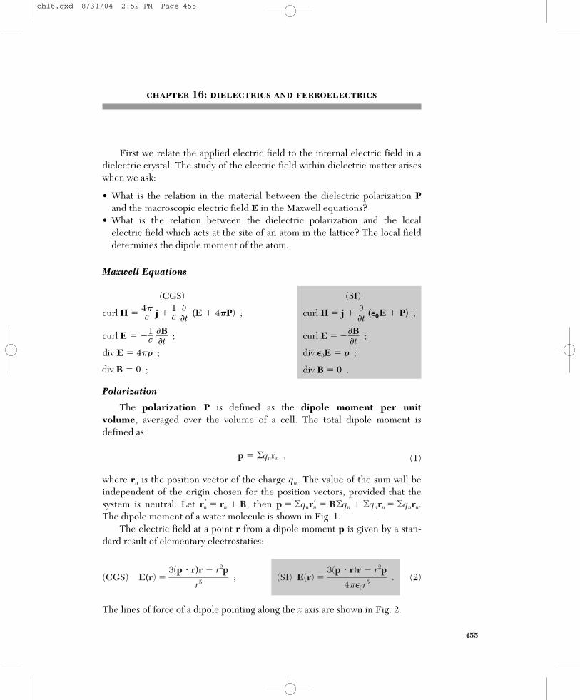
The polarization P is defined as the dipole moment per unit volume, averaged over the volume of a cell. The total dipole moment is defined as
(1)
where rn is the position vector of the charge qn. The value of the sum will beindependent of the origin chosen for the position vectors, provided that thesystem is neutral: Let then The dipole moment of a water molecule is shown in Fig. 1.
The electric field at a point r from a dipole moment p is given by a stan-dard result of elementary electrostatics:
(CGS) (2)
The lines of force of a dipole pointing along the z axis are shown in Fig. 2.
(SI) E(r) � 3(p � r)r � r2p
4��0r5
.E(r) � 3(p � r)r � r2p
r5 ;
p � �qnr�n � R�qn � �qnrn � �qnrn.r�n � rn � R;
p � �qnrn ,
(SI)
curl H � j � ��t (�0
E � P) ;
curl E � ��B�t ;
div �0E � � ;
div B � 0 .
(CGS)
curl H � 4�c j � 1c
��t (E � 4�P) ;
curl E � �1c �B
�t ;
div E � 4�� ;
div B � 0 ;
ch16.qxd 8/31/04 2:52 PM Page 455

MACROSCOPIC ELECTRIC FIELD
One contribution to the electric field inside a body is that of the appliedelectric field, defined as
(3)
The other contribution to the electric field is the sum of the fields of allcharges that constitute the body. If the body is neutral, the contribution to theaverage field may be expressed in terms of the sum of the fields of atomicdipoles.
We define the average electric field E(r0) as the average field over thevolume of the crystal cell that contains the lattice point r0:
(4)
where e(r) is the microscopic electric field at the point r. The field E is amuch smoother quantity than the microscopic field e. We could well havewritten the dipole field (2) as e(r) because it is a microscopic unsmoothedfield.
We call E the macroscopic electric field. It is adequate for all problemsin the electrodynamics of crystals provided that we know the connection be-tween E, the polarization P, and the current density j, and provided that thewavelengths of interest are long in comparison with the lattice spacing.1
To find the contribution of the polarization to the macroscopic field, wecan simplify the sum over all the dipoles in the specimen. By a famous theo-rem of electrostatics2 the macroscopic electric field caused by a uniform polar-ization is equal to the electric field in vacuum of a fictitious surface charge
E(r0) � 1Vc
� dV e(r) ,
E0 � field produced by fixed charges external to the body .
456
1A detailed derivation of the Maxwell equations for the macroscopic fields E and B, startingfrom the Maxwell equations in terms of the microscopic fields e and h, is given by E. M. Purcell,Electricity and magnetism, 2nd ed., McGraw-Hill, 1985.
2The electrostatic potential in CGS units of a dipole p is �(r) � p � grad(1/r). For a volumedistribution of polarization P we have
which by a vector identity becomes
If P is constant, then div P � 0 and by the Gauss theorem we have
where dS is an element of charge on the surface of the body. This completes the proof.
�(r) � � dS Pn
r � � dS r ,
�(r) � � dV ��1r div P � div Pr� .
�(r) � � dV �P � grad 1r� ,
ch16.qxd 8/31/04 2:52 PM Page 456

density � � P on the surface of the body. Here is the unit normal to thesurface, drawn outward from the polarized matter.
We apply the result to a thin dielectric slab (Fig. 3a) with a uniform vol-ume polarization P. The electric field E1(r) produced by the polarization isequal to the field produced by the fictitious surface charge density � � Pon the surface of the slab. On the upper boundary the unit vector is directedupward and on the lower boundary is directed downward. The upper bound-ary bears the fictitious charge � � P � P per unit area, and the lowerboundary bears �P per unit area.
The electric field E1 due to these charges has a simple form at any pointbetween the plates, but comfortably removed from their edges. By Gauss’s law
(CGS) (4a)
We add E1 to the applied field E0 to obtain the total macroscopic field inside the slab, with the unit vector normal to the plane of the slab:
(CGS) (5)
(SI)
We define
(6)
This field is smoothly varying in space inside and outside the body and satisfiesthe Maxwell equations as written for the macroscopic field E. The reason E1 isa smooth function when viewed on an atomic scale is that we have replaced the discrete lattice of dipoles pj with the smoothed polarization P.
E1 � field of the surface charge denisty n � P on the boundary .
E � E0 � E1 � E0 � P�0
z .
E � E0 � E1 � E0 � 4�Pz ;
z
(SI) E1 � �
� ��0
� P�0
.E1 � �4� � � � �4�P ;
nn
nn
nn
16 Dielectrics and Ferroelectrics 457
= –P
= +P
EI(r)
P
EI(r)
(b)(a)
Figure 3 (a) A uniformly polarized dielectric slab, with the polarization vector P normal to theplane of the slab. (b) A pair of uniformly charged parallel plates which give rise to the identicalelectric field E1 as in (a). The upper plate has the surface charge density � �P, and the lowerplate has � �P.
ch16.qxd 8/31/04 2:52 PM Page 457

Depolarization Field, E1
If the polarization is uniform within the body, the only contributions to themacroscopic field are from E0 and E1:
(7)
Here E0 is the applied field and E1 is the field due to the uniform polarization.The field E1 is called the depolarization field, for within the body it
tends to oppose the applied field E0 as in Fig. 4. Specimens in the shape of ellipsoids, a class that includes spheres, cylinders, and discs as limiting forms,have an advantageous property: a uniform polarization produces a uniform de-polarization field inside the body. This is a famous mathematical result demon-strated in classic texts on electricity and magnetism.3
If Px, Py, Pz are the components of the polarization P referred to the principalaxes of an ellipsoid, then the components of the depolarization field are written
(CGS) (8)
(SI)
Here Nx, Ny, Nz are the depolarization factors; their values depend on theratios of the principal axes of the ellipsoid. The N’s are positive and satisfy thesum rule Nx � Ny � Nz � 4� in CGS, and Nx � Ny � Nz � 1 in SI.
Values of N parallel to the figure axis of ellipsoids of revolution are plottedin Fig. 5. Additional cases have been calculated by Osborn4 and by Stoner. Inlimiting cases N has the values:
N NShape Axis (CGS) (SI)
Sphere any 4�/3 1/3Thin slab normal 4� 1Thin slab in plane 0 0Long circular cylinder longitudinal 0 0Long circular cylinder transverse 2� 1/2
E1x � �NxPx
�0 ; E1y � �
NyPy
�0 ; E1z � �
NzPz�0
.
E1x � �NxPx ; E1y � �NyPy ; E1z � �NzPz ;
E � E0 � E1 .
458
3R. Becker, Electromagnetic fields and interactions, Blaisdell, 1964, pp. 102–107.4J. A. Osborn, Phys. Rev. 67, 351 (1945); E. C. Stoner, Philosophical Magazine 36, 803 (1945).
We can reduce the depolarization field to zero in two ways, either by workingparallel to the axis of a long fine specimen or by making an electrical connectionbetween electrodes deposited on the opposite surfaces of a thin slab.
ch16.qxd 8/31/04 2:52 PM Page 458

A uniform applied field E0 will induce uniform polarization in an ellipsoid.We introduce the dielectric susceptibility � such that the relations
(CGS) (9)
connect the macroscopic field E inside the ellipsoid with the polarization P.Here �SI � 4��CGS.
If E0 is uniform and parallel to a principal axis of the ellipsoid, then
(CGS) (10)
by (8), whence
(CGS) (11)
(SI)
The value of the polarization depends on the depolarization factor N.
P � �(�0E0 � NP) ; P � ��0
1 � N� E0 .
P � �(E0 � NP) ; P � �
1 � N� E0 ;
(SI) E � E0 � NP�0
,E � E0 � E1 � E0 � NP ;
(SI) P � �0�E ,P � �E ;
16 Dielectrics and Ferroelectrics 459
E1E0 P
– – ––
––
––
–––
++++
+++
++ + +
Figure 4 The depolarization field E1 is op-posite to P. The fictitious surface charges areindicated: the field of these charges is E1
within the ellipsoid.
1.0
0.8
0.6
0.4
0.2
0
1.0
0.8
0.6
0.4
0.2
0
CGS
N/4
�
N
SI
10 2 3c/a
4 5 6
Figure 5 Depolarization factor Nparallel to the figure axis of ellip-soids of revolution, as a functionof the axial ratio c/a.
ch16.qxd 8/31/04 2:52 PM Page 459

LOCAL ELECTRIC FIELD AT AN ATOM
The value of the local electric field that acts at the site of an atom is signif-icantly different from the value of the macroscopic electric field. We can con-vince ourselves of this by consideration of the local field at a site with a cubicarrangement of neighbors5 in a crystal of spherical shape. The macroscopicelectric field in a sphere is
(CGS) (12)
(SI)
by (10).But consider the field that acts on the atom at the center of the sphere
(this atom is not unrepresentative). If all dipoles are parallel to the z axis andhave magnitude p, the z component of the field at the center due to all otherdipoles is, from (2),
(CGS) (13)
In SI we replace p by p/4��0. The x, y, z directions are equivalent because ofthe symmetry of the lattice and of the sphere; thus
whence Edipole � 0.The correct local field is just equal to the applied field, Elocal � E0, for an
atom site with a cubic environment in a spherical specimen. Thus the localfield is not the same as the macroscopic average field E.
We now develop an expression for the local field at a general lattice site,not necessarily of cubic symmetry. The local field at an atom is the sum of theelectric field E0 from external sources and of the field from the dipoles withinthe specimen. It is convenient to decompose the dipole field so that part of thesummation over dipoles may be replaced by integration.
We write
(14)Elocal � E0 � E1 � E2 � E3 .
� i
z2i
r5i
� � i
x2i
r5i
� � i
y2i
r5i
,
Edipole � p � i
3z2i � ri
2
r
5i
� p � i
2z2i � x2
i � y2i
r
5i
.
E � E0 � E1 � E0 � 13�0
P ,
E � E0 � E1 � E0 � 4�3
P ;
460
5Atom sites in a cubic crystal do not necessarily have cubic symmetry: thus the O2� sites in thebarium titanate structure of Fig. 10 do not have a cubic environment. However, the Na� and Cl�
sites in the NaCl structure and the Cs� and Cl� sites in the CsCl structure have cubic symmetry.
ch16.qxd 8/31/04 2:52 PM Page 460

HereE0 � field produced by fixed charges external to the body;E1 � depolarization field, from a surface charge density � P on the outer
surface of the specimen;E2 � Lorentz cavity field: field from polarization charges on inside of a
spherical cavity cut (as a mathematical fiction) out of the specimen with thereference atom as center, as in Fig. 6; E1 � E2 is the field due to uniform po-larization of the body in which a hole has been created;
E3 � field of atoms inside cavity.The contribution E1 � E2 � E3 to the local field is the total field at one
atom caused by the dipole moments of all the other atoms in the specimen:
(CGS) (15)
and in SI we replace pi by pi/4��0.Dipoles at distances greater than perhaps ten lattice constants from the
reference site make a smoothly varying contribution to this sum, a contribu-tion which may be replaced by two surface integrals. One surface integral istaken over the outer surface of the ellipsoidal specimen and defines E1, as inEq. (6). The second surface integral defines E2 and may be taken over any interior surface that is a suitable distance (say 50 Å) from the referencesite. We count in E3 any dipoles not included in the volume bounded by the inner and outer surfaces. It is convenient to let the interior surface bespherical.
E1 � E2 � E3 � �i
3(pi �
ri)ri � r2i pi
r5i
,
n
16 Dielectrics and Ferroelectrics 461
E0
E1 fromouter
boundary
E2 fromsurface ofspherical
cavity
E3 from dipolesinside sphere
Figure 6 The internal electric field on an atom in a crystal is the sum of the external applied fieldE0 and of the field due to the other atoms in the crystal. The standard method of summing the di-pole fields of the other atoms is first to sum individually over a moderate number of neighboringatoms inside an imaginary sphere concentric with the reference atom: this defines the field E3,which vanishes at a reference site with cubic symmetry. The atoms outside the sphere can betreated as a uniformly polarized dielectric. Their contribution to the field at the reference point isE1 � E2, where E1 is the depolarization field associated with the outer boundary and E2 is thefield associated with the surface of the spherical cavity.
ch16.qxd 8/31/04 2:52 PM Page 461

Lorentz Field, E2
The field E2 due to the polarization charges on the surface of the fictitiouscavity was calculated by Lorentz. If � is the polar angle (Fig. 7) referred to thepolarization direction, the surface charge density on the surface of the cavity is�P cos �. The electric field at the center of the spherical cavity of radius a is
(CGS) (16)
(SI)
This is the negative of the depolarization field E1 in a polarized sphere, so thatE1 � E2 � 0 for a sphere.
Field of Dipoles Inside Cavity, E3
The field E3 due to the dipoles within the spherical cavity is the only termthat depends on the crystal structure. We showed for a reference site withcubic surroundings in a sphere that E3 � 0 if all the atoms may be replaced bypoint dipoles parallel to each other. The total local field at a cubic site is, from(14) and (16),
(CGS) (17)
(SI)
This is the Lorentz relation: the field acting at an atom in a cubic site is themacroscopic field E of Eq. (7) plus 4�P/3 or P/3�0 from the polarization of theother atoms in the specimen. Experimental data for cubic ionic crystals sup-port the Lorentz relation.
Elocal � E � 13�0
P .
Elocal � E0 � E1 �
4�3
P � E �
4�3
P ;
E2 � 13�0
P .
E2 � ��
0(a� 2)(2�a sin �)(a d�)(P cos �)( cos �) �
4�3
P ;
462
a sin �
Charge on ring =2� a sin � • a d� • P cos �
a d�
P
– – –––
–– –
+ +++
+ +++
�a
Figure 7 Calculation of the field in a spherical cavity ina uniformly polarized medium.
ch16.qxd 8/31/04 2:52 PM Page 462

DIELECTRIC CONSTANT AND POLARIZABILITY
The dielectric constant � of an isotropic or cubic medium relative to vac-uum is defined in terms of the macroscopic field E:
(CGS) (18)
(SI)
Remember that �SI � 4��CGS, by definition, but �SI � �CGS.The susceptibility (9) is related to the dielectric constant by
(CGS) ` (19)
In a noncubic crystal the dielectric response is described by the componentsof the susceptibility tensor or of the dielectric constant tensor:
(CGS) (20)
(SI)
The polarizability � of an atom is defined in terms of the local electricfield at the atom:
(21)
where p is the dipole moment. This definition applies in CGS and in SI, but�SI � 4��0�CGS. The polarizability is an atomic property, but the dielectricconstant will depend on the manner in which the atoms are assembled to forma crystal. For a nonspherical atom � will be a tensor.
The polarization of a crystal may be expressed approximately as the prod-uct of the polarizabilities of the atoms times the local electric field:
(22)
where Nj is the concentration and �j the polarizability of atoms j, and Eloc( j) isthe local field at atom sites j.
We want to relate the dielectric constant to the polarizabilities; the resultwill depend on the relation that holds between the macroscopic electric fieldand the local electric field. We give the derivation in CGS units and state theresult in both systems of units.
P � �j
Njpj � � j
Nj�jEloc( j) ,
p � �Elocal ,
P � �� �0E� ; �� � �� � �� .
P � ��E� ; �� � �� � 4��� .
(SI) � � P�0E
� � � 1 .� � PE
� � � 14�
;
� � �0 E � P
�0 E � 1 � � .
� � E � 4�PE
� 1 � 4�� ;
16 Dielectrics and Ferroelectrics 463
ch16.qxd 8/31/04 2:52 PM Page 463

If the local field is given by the Lorentz relation (17), then
(CGS)
and we solve for P to find the susceptibility
(CGS)(23)
By definition � � 1 � 4�� in CGS; we may rearrange (23) to obtain
(CGS) (24)
the Clausius-Mossotti relation. This relates the dielectric constant to theelectronic polarizability, but only for crystal structures for which the Lorentzlocal field (17) obtains.
Electronic Polarizability
The total polarizability may usually be separated into three parts: elec-tronic, ionic, and dipolar, as in Fig. 8. The electronic contribution arises fromthe displacement of the electron shell relative to a nucleus. The ionic contri-bution comes from the displacement of a charged ion with respect to otherions. The dipolar polarizability arises from molecules with a permanent elec-tric dipole moment that can change orientation in an applied electric field.
(SI) � � 1� � 2
�
13�0
�Nj�j ,� � 1� � 2
�
4�3
�Nj�j ;
� �
PE
�
�Nj�j
1 �
4�3
�Nj�j
.
P � (�Nj�j) �E �
4�3
P� ;
464
Total polarizability (real part)
Frequency
UHF tomicrowaves
Infrared
dipolar
ionic
electronic
Ultra-violet
�
�
�
Figure 8 Frequency dependence of the several contributions to the polarizability.
ch16.qxd 8/31/04 2:52 PM Page 464

In heterogeneous materials there is usually also an interfacial polarizationarising from the accumulation of charge at structural interfaces. This is of littlefundamental interest, but it is of considerable practical interest because com-mercial insulating materials are usually heterogeneous.6
The dielectric constant at optical frequencies arises almost entirely fromthe electronic polarizability. The dipolar and ionic contributions are small athigh frequencies because of the inertia of the molecules and ions. In the opti-cal range (24) reduces to
(CGS) (25)
here we have used the relation n2 � �, where n is the refractive index.By applying (25) to large numbers of crystals we determine in Table 1 em-
pirical values of the electronic polarizabilities that are reasonably consistentwith the observed values of the refractive index. The scheme is not entirelyself-consistent, because the electronic polarizability of an ion depends somewhat on the environment in which it is placed. The negative ions arehighly polarizable because they are large.
n2 � 1
n2 � 2
�
4�3
�Nj�j(electronic) ;
16 Dielectrics and Ferroelectrics 465
6For references see D. E. Aspnes, Am. J. Phys. 50, 704 (1982).
Table 1 Electronic polarizabilities of atoms and ions, in 10�24 cm3
He Li� Be2� B3� C4�
Pauling 0.201 0.029 0.008 0.003 0.0013JS 0.029
O2� F� Ne Na� Mg2� Al3� Si4�
Pauling 3.88 1.04 0.390 0.179 0.094 0.052 0.0165JS-(TKS) (2.4) 0.858 0.290
S2� Cl� Ar K� Ca2� Se3� Ti4�
Pauling 10.2 3.66 1.62 0.83 0.47 0.286 0.185JS-(TKS) (5.5) 2.947 1.133 (1.1) (0.19)
Se2� Br� Kr Rb� Sr2� Y3� Zr4�
Pauling 10.5 4.77 2.46 1.40 0.86 0.55 0.37JS-(TKS) (7.) 4.091 1.679 (1.6)
Te2� I� Xe Cs� Ba2� La3� Ce4�
Pauling 14.0 7.10 3.99 2.42 1.55 1.04 0.73JS-(TKS) (9.) 6.116 2.743 (2.5)
Values from L. Pauling, Proc. R. Soc. London A114, 181 (1927); S. S. Jaswal and T. P.Sharma, J. Phys. Chem. Solids 34, 509 (1973); and J. Tessman, A. Kahn, and W. Shockley, Phys.Rev. 92, 890 (1953). The TKS polarizabilities are at the frequency of the D lines of sodium. Thevalues are in CGS; to convert to SI, multiply by 9 � 10�15.
ch16.qxd 8/31/04 2:52 PM Page 465

Classical Theory of Electronic Polarizability. An electron bound har-monically to an atom will show resonance absorption at a frequency 0 �
(�/m)1/2, where � is the force constant. The displacement x of the electron occasioned by the application of a field Eloc is given by
(26)
so that the static electronic polarizability is
(27)
The electronic polarizability will depend on frequency, and it is shown inthe following example that for frequency
(CGS) (28)
but in the visible region the frequency dependence (dispersion) is not usuallyvery important in most transparent materials.
EXAMPLE: Frequency dependence. Find the frequency dependence of the elec-tronic polarizability of an electron having the resonance frequency 0, treating the sys-tem as a simple harmonic oscillator.
The equation of motion in the local electric field Eloc sin t is
so that, for x � x0 sin t,
The dipole moment has the amplitude
from which (28) follows.
In quantum theory the expression corresponding to (28) is
(CGS) (29)
where fij is called the oscillator strength of the electric dipole transition be-tween the atomic states i and j. Near a transition the polarizability changessign (Fig. 8).
�(electronic) �
e2
m � j
fij
2ij � 2 ,
p0 � �ex0 �
e2Eloc
m( 20 � 2)
,
m(� 2 � 2
0)x0 � �eEloc .
md2xdt2 � m 2
0x � �eEloc sin t ,
�(electronic) �
e2/m 2
0 � 2 ;
�(electronic) � p/Eloc � �ex/Eloc � e2/m 20 .
�eEloc � �x � m 20
x ,
466
ch16.qxd 8/31/04 2:52 PM Page 466

STRUCTURAL PHASE TRANSITIONS
It is not uncommon for crystals to transform from one crystal structure toanother as the temperature or pressure is varied. The stable structure A at absolute zero generally has the lowest accessible internal energy of all the pos-sible structures. Even this selection of a structure A can be varied with appli-cation of pressure, because a low atomic volume will favor closest-packed oreven metallic structures. Hydrogen and xenon, for example, become metallicunder extreme pressure.
Some other structure B may have a softer or lower frequency phononspectrum than A. As the temperature is increased the phonons in B will bemore highly excited (higher thermal average occupancies) than the phonons inA. Because the entropy increases with the occupancy, the entropy of B will be-come higher than the entropy of A as the temperature is increased.
It is thereby possible for the stable structure to transform from A to B asthe temperature is increased. The stable structure at a temperature T is deter-mined by the minimum of the free energy F � U � TS. There will be a transi-tion from A to B if a temperature Tc exists (below the melting point) such thatFA(Tc) � FB(Tc).
Often several structures have nearly the same internal energy at absolutezero. The phonon dispersion relations for the structures may, however, be ratherdifferent. The phonon energies are sensitive to the number and arrangement ofnearby atoms; these are the quantities that change as the structure is changed.
Some structural phase transitions have only small effects on the macro-scopic physical properties of the material. However, if the transition is influ-enced by an applied stress, the crystal may yield mechanically quite easily nearthe transition temperature because the relative proportions in the two phaseswill change under stress. Some other structural phase transitions may havespectacular effects on the macroscopic electrical properties.
Ferroelectric transitions are a subgroup of structural phase transitions, asubgroup marked by the appearance of a spontaneous dielectric polarization inthe crystal. Ferroelectrics are of theoretical and technical interest becausethey often have unusually high and unusually temperature-dependent valuesof the dielectric constant, the piezoelectric effect, the pyroelectric effect, andelectro-optical effects, including optical frequency doubling.
FERROELECTRIC CRYSTALS
A ferroelectric crystal exhibits an electric dipole moment even in the ab-sence of an external electric field. In the ferroelectric state the center of posi-tive charge of the crystal does not coincide with the center of negative charge.
The plot of polarization versus electric field for the ferroelectric stateshows a hysteresis loop. A crystal in a normal dielectric state usually does not
16 Dielectrics and Ferroelectrics 467
ch16.qxd 8/31/04 2:52 PM Page 467

show significant hysteresis when the electric field is increased and then re-versed, both slowly.
Ferroelectricity usually disappears above a certain temperature called thetransition temperature. Above the transition the crystal is said to be in a para-electric state. The term paraelectric suggests an analogy with paramagnetism:
468
(a)
(b)
(c)
Die
lect
ric
cons
tant
�dP
/dT
(C
cm
–2 K
–1)
c P (a
rbitr
ary
units
)
3
2
1
0500
T(°C)
T0 = 449°CTc = 492°C
dPdT
� –1
× 1
04
400 600
50
0.0
40
30
1000
0.1
0.2
0.3
0.4
2000
4000
6000
8000
10000
200 300
Temperature (°C)
400 500 600
Figure 9 The temperature variation of (a) the dielectric constant �, (b) the pyroelectric coeffi-cient dP/dT, and (c) the specific heat cp, of PbTiO3. (After Remeika and Class.)
ch16.qxd 8/31/04 2:52 PM Page 468
there is usually a rapid drop in the dielectric constant as the temperature increases.
In some crystals the ferroelectric dipole moment is not changed by anelectric field of the maximum intensity which it is possible to apply beforecausing electrical breakdown. In these crystals we are often able to observe achange in the spontaneous moment when the temperature is changed (Fig. 9).Such crystals are called pyroelectric. Lithium niobate, LiNbO3, is pyroelec-tric at room temperature. It has a high transition temperature (Tc � 1480 K)and a high saturation polarization (50 C/cm2). It can be “poled,” whichmeans given a remanent polarization, by an electric field applied over 1400 K.
Classification of Ferroelectric Crystals
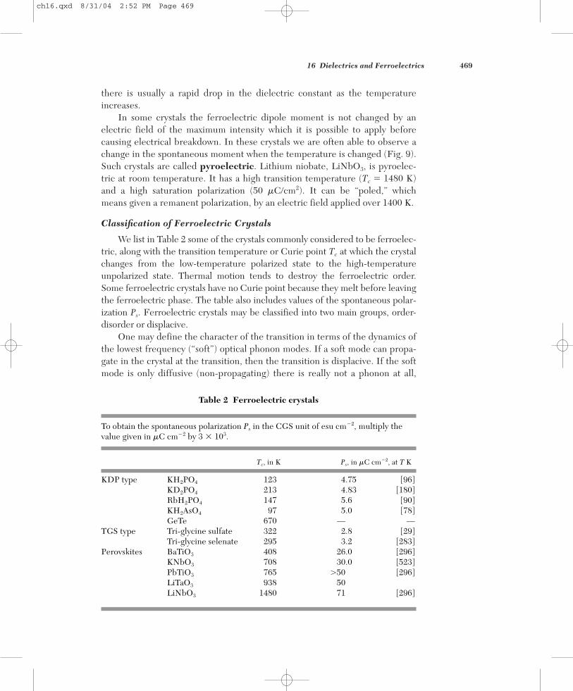
We list in Table 2 some of the crystals commonly considered to be ferroelec-tric, along with the transition temperature or Curie point Tc at which the crystalchanges from the low-temperature polarized state to the high-temperature unpolarized state. Thermal motion tends to destroy the ferroelectric order.Some ferroelectric crystals have no Curie point because they melt before leavingthe ferroelectric phase. The table also includes values of the spontaneous polar-ization Ps. Ferroelectric crystals may be classified into two main groups, order-disorder or displacive.
One may define the character of the transition in terms of the dynamics ofthe lowest frequency (“soft”) optical phonon modes. If a soft mode can propa-gate in the crystal at the transition, then the transition is displacive. If the softmode is only diffusive (non-propagating) there is really not a phonon at all,
16 Dielectrics and Ferroelectrics 469
Table 2 Ferroelectric crystals
To obtain the spontaneous polarization Ps in the CGS unit of esu cm�2, multiply thevalue given in C cm�2 by 3 � 103.
Tc, in K Ps, in C cm�2, at T K
KDP type KH2PO4 123 4.75 [96]KD2PO4 213 4.83 [180]RbH2PO4 147 5.6 [90]KH2AsO4 97 5.0 [78]GeTe 670 — —
TGS type Tri-glycine sulfate 322 2.8 [29]Tri-glycine selenate 295 3.2 [283]
Perovskites BaTiO3 408 26.0 [296]KNbO3 708 30.0 [523]PbTiO3 765 �50 [296]LiTaO3 938 50LiNbO3 1480 71 [296]
ch16.qxd 8/31/04 2:52 PM Page 469

but is only a large amplitude hopping motion between the wells of the order-disorder system. Many ferroelectrics have soft modes that fall between thesetwo extremes.
The order-disorder class of ferroelectrics includes crystals with hydrogenbonds in which the motion of the protons is related to the ferroelectric properties, as in potassium dihydrogen phosphate (KH2PO4) and isomorphoussalts. The substitution of deuterons for protons nearly doubles Tc, although thefractional change in the molecular weight of the compound is less than 2 percent:
KH2PO4 KD2PO4 KH2AsO4 KD2AsO4
Curie temperature 123 K 213 K 97 K 162 K
This extraordinarily large isotope shift is believed to be a quantum effect in-volving the mass-dependence of the de Broglie wavelength. Neutron diffractiondata show that above the Curie temperature the proton distribution along thehydrogen bond is symmetrically elongated. Below the Curie temperature thedistribution is more concentrated and asymmetric with respect to neighboringions, so that one end of the hydrogen bond is preferred by the proton over theother end, giving a polarization.
The displacive class of ferroelectrics includes ionic crystal structuresclosely related to the perovskite and ilmenite structures. The simplest ferro-electric crystal is GeTe with the sodium chloride structure. We shall devoteourselves primarily to crystals with the perovskite structure, Fig. 10.
Consider the order of magnitude of the ferroelectric effects in barium titanate: the observed saturation polarization Ps at room temperature (Fig. 11)
470
(a) (b)
Ba2+
Ti4+Ti4+
Ba2+
O2–
Figure 10 (a) The crystal structure of barium titanate. The prototype crystal is calcium titanate(perovskite). The structure is cubic, with Ba2� ions at the cube corners, O2� ions at the face cen-ters, and a Ti4� ion at the body center. (b) Below the Curie temperature the structure is slightlydeformed, with Ba2� and Ti4� ions displaced relative to the O2� ions, thereby developing a dipolemoment. The upper and lower oxygen ions may move downward slightly.
ch16.qxd 8/31/04 2:52 PM Page 470

is 8 � 104 esu cm�2. The volume of a cell is (4 � 10�8)3 � 64 � 10�24 cm3, sothat the dipole moment of a cell is
(CGS)
(SI)
If the positive ions Ba2� and Ti4� were moved by � � 0.1 Å with respect to thenegative O2� ions, the dipole moment of a cell would be 6e� 3 � 10�18 esucm. In LiNbO3 the displacements are considerably larger, being 0.9 Å and 0.5 Åfor the lithium and niobum ions respectively, giving the larger Ps.
DISPLACIVE TRANSITIONS
Two viewpoints contribute to an understanding of a ferroelectric displacivetransition and by extension to displacive transitions in general. We may speak ofa polarization catastrophe in which for some critical condition the polarizationor some Fourier component of the polarization becomes very large. Equally, wemay speak of the condensation of a transverse optical phonon. Here the wordcondensation is to be understood in the Bose-Einstein sense (TP, p. 199) of atime-independent displacement of finite amplitude. This can occur when thecorresponding TO phonon frequency vanishes at some point in the Brillouinzone. LO phonons always have higher frequencies than the TO phonons of thesame wavevector, so we are not concerned with LO phonon condensation.
�
p � (3 � 10�1 C m� 2)(64 � 10� 30 m3) � 2 � 10� 29 C m .
p � (8 � 104 esu cm�2)(64 � 10�24 cm�3) � 5 � 10�18 esu cm ;
16 Dielectrics and Ferroelectrics 471
20 × 10–2
16
12
8
4
0–160–200
Ps PsPs
P s (c
oulo
mbs
/m2 )
Temperature (°C)–120 –80 –40 0 40 80 120
Monoclinic TetragonalRhombohedral
Figure 11 Spontaneous polarization projected on cube edge of barium titanate, as a function oftemperature. (After W. J. Merz.)
ch16.qxd 8/31/04 2:52 PM Page 471

In a polarization catastrophe the local electric field caused by the ionicdisplacement is larger than the elastic restoring force, thereby giving an asym-metrical shift in the positions of the ions. Higher order restoring forces willlimit the shift to a finite displacement.
The occurrence of ferroelectricity (and antiferroelectricity) in many perovskite-structure crystals suggests that this structure is favorably disposedto a displacive transition. Local field calculations make clear the reason for thefavored position of this structure: the O2� ions do not have cubic surround-ings, and the local field factors turn out to be unusually large.
We give first the simple form of the catastrophe theory, supposing that thelocal field at all atoms is equal to E � 4�P/3 in CGS or E � P/3�0 in SI. The theory given now leads to a second-order transition; the physical ideas can be car-ried over to a first-order transition. In a second-order transition there is no latentheat; the order parameter (in this instance, the polarization) is not discontinuousat the transition temperature. In a first-order transition there is a latent heat; theorder parameter changes discontinuously at the transition temperature.
We rewrite (24) for the dielectric constant in the form
(CGS) (30)
where �i is the electronic plus ionic polarizability of an ion of type i and Ni isthe number of ions i per unit volume. The dielectric constant becomes infiniteand permits a finite polarization in zero applied field when
(CGS) (31)
This is the condition for a polarization catastrophe.The value of � in (30) is sensitive to small departures of � Ni�i from the
critical value 3/4�. If we write
(CGS) (32)
where s 1, the dielectric constant in (30) becomes
(33)
Suppose near the critical temperature s varies linearly with temperature:
(34)
where � is a constant. Such a variation of s or � Ni�i might come from normalthermal expansion of the lattice. The dielectric constant has the form
(35)
close to the observed temperature variation in the paraelectric state, Fig. 12.
� �
�
T � Tc ,
s � (T � Tc)/� ,
� � 1/s .
(4�/3)�Ni�i � 1 � 3s ,
�Ni�i � 3/4� .
� �
1 �
8�3
� Ni�i
1 �
4�3
� Ni�i
,
472
ch16.qxd 8/31/04 2:52 PM Page 472

Soft Optical Phonons
The Lyddane-Sachs-Teller relation (Chapter 14) is
(36)
The static dielectric constant increases when the transverse optical phonon fre-quency decreases. When the static dielectric constant �(0) has a high value,such as 100 to 10,000, we find that T has a low value.
When T � 0 the crystal is unstable and �(0) is infinite because there is noeffective restoring force. The ferroelectric BaTiO3 at 24°C has a TO mode at12 cm�1, a low frequency for an optical mode.
If the transition to a ferroelectric state is first order, we do not find T � 0or �(0) � � at the transition. The LST relation suggests only that �(0) extrapo-lates to a singularity at a temperature T0 below Tc.
The association of a high static dielectric constant with a low-frequencyoptical mode is supported by experiments on strontium titanate, SrTiO3. According to the LST relation, if the reciprocal of the static dielectric constanthas a temperature dependence 1/�(0) � (T � T0), then the square of the optical mode frequency will have a similar temperature dependence: 2
T � (T � T0), if L is independent of temperature. The result for 2T is
very well confirmed by Fig. 13. Measurements of T versus T for another ferroelectric crystal, SbSI, are shown in Fig. 14.
2T/ 2
L � �(�)/�(0) .
16 Dielectrics and Ferroelectrics 473
Die
lect
ric
cons
tant
900
100
010
500
2 3 4 5
1000 in (K)–1
6 7 8 9 10 11 12
Ba0.5Sr0.5TiO3
Ca0.2Sr0.8TiO3
BaTiO3
SrTiO3
KTO3
CaTiO3
T – Tc
Figure 12 Dielectric constant versus 1/(T � Tc) in the paraelectric state (T � Tc) of perovskites,after G. Rupprecht and R. O. Bell.
ch16.qxd 8/31/04 2:52 PM Page 473

Landau Theory of the Phase Transition
A ferroelectric with a first-order phase transition between the ferroelec-tric and the paraelectric state is distinguished by a discontinuous change of thesaturation polarization at the transition temperature. The transition betweenthe normal and superconducting states is a second-order transition, as is the
474
Rec
ipro
cal o
f die
lect
ric
cons
tant
(Fre
quen
cy)2
in u
nits
102
4 H
z2
10
0.003
0.002
0.001
0100 5004003002000
6
2
0
4
8
12
T2
1�
Temperature, K
Figure 13 Plot of the square of the frequency of the zero wavevector transverse optical modeagainst temperature, for SrTiO3, as observed in neutron diffraction experiments by Cowley. The bro-ken line is the reciprocal of the dielectric constant from the measurements of Mitsui and Westphal.
50
40
30
20
10
0140
Fre
quen
cy, i
n cm
–1
160 120 100 80|T – Tc|, in K
60 40 20 0
Figure 14 Decrease of a transverse phonon frequency as the Curie temperature is approachedfrom below, in the ferroelectric crystal antimony sulphoiodide, SbSI. (After Raman scattering experiments by C. H. Perry and D. K. Agrawal.)
ch16.qxd 8/31/04 2:52 PM Page 474

transition between the ferromagnetic and paramagnetic states. In these transi-tions the degree of order goes to zero without a discontinuous change as thetemperature is increased.
We can obtain a consistent formal thermodynamic theory of the behaviorof a ferroelectric crystal by considering the form of the expansion of the en-ergy as a function of the polarization P. We assume that the Landau7 free en-ergy density in one dimension may be expanded formally as
(37)
where the coefficients gn depend on the temperature.The series does not contain terms in odd powers of P if the unpolarized
crystal has a center of inversion symmetry, but crystals are known in which oddpowers are important. Power series expansions of the free energy do not al-ways exist, for nonanalytic terms are known to occur, especially when very neara transition. For example, the transition in KH2PO4 appears to have a logarith-mic singularity in the heat capacity at the transition, which is not classifiable aseither first or second order.
The value of P in thermal equilibrium is given by the minimum of as afunction of P; the value of at this minimum defines the Helmholtz free en-ergy F(T,E). The equilibrium polarization in an applied electric field E satis-fies the extremum condition
(38)
In this section we assume that the specimen is a long rod with the external ap-plied field E parallel to the long axis.
To obtain a ferroelectric state we must suppose that the coefficient of theterm in P2 in (37) passes through zero at some temperature T0:
(39)
where � is taken as a positive constant and T0 may be equal to or lower thanthe transition temperature. A small positive value of g2 means that the lattice is“soft” and is close to instability. A negative value of g2 means that the unpolar-ized lattice is unstable. The variation of g2 with temperature is accounted forby thermal expansion and other effects of anharmonic lattice interactions.
Second-Order Transition
If g4 in (37) is positive, nothing new is added by the term in g6, and thismay then be neglected. The polarization for zero applied electric field is foundfrom (38):
(40)�(T � T0)Ps � g4P3s � 0 ,
g2 � �(T � T0) ,
�F�P
� 0 � �E � g2P � g4P3 � g6P
5 �
Á .
FF
F(P;T,E) � �EP � g0 �
12
g2P2 �
14
g4P4 �
16
g6P6 �
Á ,
F
16 Dielectrics and Ferroelectrics 475
7In TP, see pp. 69 and 298 for a discussion of the Landau function.
ch16.qxd 8/31/04 2:52 PM Page 475

so that either Ps � 0 or P2s � (�/g4)(T0 � T). For T T0 the only real root of (40)
is at Ps � 0, because � and g4 are positive. Thus T0 is the Curie temperature. ForT � T0 the minimum of the Landau free energy in zero applied field is at
(41)
as plotted in Fig. 15. The phase transition is a second-order transition becausethe polarization goes continuously to zero at the transition temperature. Thetransition in LiTaO3 is an example (Fig. 16) of a second-order transition.
�Ps � � (�/g4)1/2(T0 � T)1/2 ,
476
P s(T
)P s
(0)
0.6
0.20
0.4
0.2
00.4 0.6 0.8 1.0
T/Tc
Figure 15 Spontaneous polarization versus temperature, for a second-order phase transition.
104 /
�
25
450
20
15
10
5
0500 550 600 650 700 750 800
Temperature (°C)
Figure 16 Temperature variation of the polar-axis static dielectric constant of LiTaO3. (AfterGlass.)
ch16.qxd 8/31/04 2:52 PM Page 476

First-Order Transition
The transition is first order if g4 in (37) is negative. We must now retain g6
and take it positive in order to restrain from going to minus infinity (Fig. 17).The equilibrium condition for E � 0 is given by (38):
(42)
so that either Ps � 0 or
(43)
At the transition temperature Tc the free energies of the paraelectric andferroelectric phases will be equal. That is, the value of for Ps � 0 will be equalto the value of at the minimum given by (43). In Fig. 18 we show the charac-teristic variation with temperature of Ps for a first-order phase transition;
FF
�(T � T0) � �g4 �P2s � g6 P4
s � 0 .
�(T � T0)Ps � �g4 �P3s � g6 P5
s � 0 ,
F
16 Dielectrics and Ferroelectrics 477
P2
Lan
dau
free
ene
rgy
0
T > Tc
T < TcTc
Figure 17 Landau free energy function versus (polarization)2 in a first-order transition, at repre-sentative temperatures. At Tc the Landau function has equal minima at P � 0 and at a finite P asshown. For T below Tc the absolute minimum is at larger values of P; as T passes through Tc thereis a discontinuous change in the position of the absolute minimum. The arrows mark the minima.
30
20
–80
P s in
10–
2 C
m–2
T – Tc in deg C
10
0–60 –40 –20 0 20 40
Figure 18 Calculated valuesof the spontaneous polar-ization as a function of tem-perature, with parameters asfor barium titanate. (After W. Cochran.)
ch16.qxd 8/31/04 2:52 PM Page 477

contrast this with the variation shown in Fig. 15 for a second-order phase tran-sition. The transition in BaTiO3 is first order.
The dielectric constant is calculated from the equilibrium polarization inan applied electric field E and is found from (38). In equilibrium at tempera-tures over the transition, the terms in P4 and P6 may be neglected; thus E �
�(T � T0)P, or
(CGS) (44)
of the form of (36). The result applies whether the transition is of the first orsecond order, but if second order we have T0 � Tc; if first order, then T0 � Tc.Equation (39) defines T0, but Tc is the transition temperature.
�(T � Tc) � 1 � 4�P/E � 1 � 4�/�(T � T0) ,
478
Ferrodistortive
Antidistortive
Pyroelectric
Ferroelectric
Antipolar
Antiferroelectric
Charged atoms or groups
Uncharged atoms or groups
T > Tc T < TcT < Tc
Applied field
– – –
– –
+
+ –
+
–
– – –
– –
+ +
–
– – –
– –
+ +
–
– – –
– –
+ +
–
– – –
– –
+ +
–
– – –
– –
+ +
–
– – –
– –
+ +
–
– – –
– –
+ +
–
– – –
– –
+ +
–
– – –
– –
+ +
–
– – –
– –
+ +
–
– – –
– –
+ +
–
Figure 19 Schematic representation of fundamental types of structural phase transitions from acentrosymmetric prototype. (After Lines and Glass.)
ch16.qxd 8/31/04 2:52 PM Page 478

Antiferroelectricity
A ferroelectric displacement is not the only type of instability that may develop in a dielectric crystal. Other deformations occur, as in Fig. 19. Thesedeformations, even if they do not give a spontaneous polarization, may be ac-companied by changes in the dielectric constant. One type of deformation iscalled antiferroelectric and has neighboring lines of ions displaced in oppo-site senses. The perovskite structure appears to be susceptible to many types ofdeformation, often with little difference in energy between them. The phase diagrams of mixed perovskite systems, such as the PbZrO3–PbTiO3 system,show transitions between para-, ferro-, and antiferroelectric states (Fig. 20).Several crystals believed to have an ordered nonpolar state are listed in Table 3.
Ferroelectric Domains
Consider a ferroelectric crystal (such as barium titanate in the tetragonalphase) in which the spontaneous polarization may be either up or down the caxis of the crystal. A ferroelectric crystal generally consists of regions calleddomains within each of which the polarization is in the same direction, but inadjacent domains the polarization is in different directions. In Fig. 21 the po-larization is in opposite directions. The net polarization depends on the differ-ence in the volumes of the upward- and downward-directed domains. The
16 Dielectrics and Ferroelectrics 479
PC
FE2
FE1 FT
Tem
pera
ture
(°C
)
500
450
400
350
300
250
200
150
100
50
010
A
0 20 30 40 50
Mole percent PbTiO3PbZrO3
FR(LT)
FR(HT)
PbTiO3
60 70 80 90 100
Figure 20 Ferroelectric F, antiferroelectric A, and paraelectric P phases of the lead zirconate–leadtitanate solid solution system. The subscript T denotes a tetragonal phase; C a cubic phase; R arhombohedral phase, of which there are high-temperature (HT) and low-temperature (LT) forms.Near the rhombohedral–tetragonal phase boundaries one finds very high piezoelectric coupling coefficients. (After Jaffe.)
ch16.qxd 8/31/04 2:52 PM Page 479

crystal as a whole will appear to be unpolarized, as measured by the charge onelectrodes covering the ends, when the volumes of domains in opposite sensesare equal. The total dipole moment of the crystal may be changed by themovement of the walls between domains or by the nucleation of new domains.
Figure 22 is a series of photomicrographs of a single crystal of barium titanate in an electric field normal to the plane of the photographs and parallelto the tetragonal axis. The closed curves are boundaries between domains polarized into and out of the plane of the photographs. The domain bound-aries change size and shape when the intensity of the electric field is altered.
480
Table 3 Antiferroelectric crystals
Transition temperature to Crystal antiferroelectric state, in K
WO3 1010NaNbO3 793, 911PbZrO3 506PbHfO3 488NH4H2PO4 148ND4D2PO4 242NH4H2AsO4 216ND4D2AsO4 304(NH4)2H3IO6 254
From a compilation by Walter J. Merz.
(a) (b)
P P
+ +
+ +
+ ++ +
+ +
+ +
Figure 21 (a) Schematic drawing of atomic displacements on either side of a boundary betweendomains polarized in opposite directions in a ferroelectric crystal; (b) view of a domain structure,showing 180° boundaries between domains polarized in opposite directions.
ch16.qxd 8/31/04 2:52 PM Page 480

Piezoelectricity
All crystals in a ferroelectric state are also piezoelectric: a stress Z appliedto the crystal will change the electric polarization (Fig. 23). Similarly, an elec-tric field E applied to the crystal will cause the crystal to become strained. Inschematic one-dimensional notation, the piezoelectric equations are
(CGS) (45)
where P is the polarization, Z the stress, d the piezoelectric strain constant,E the electric field, � the dielectric susceptibility, e the elastic strain, and s theelastic compliance constant. To obtain (45) in SI, replace � by �0�. These rela-tions exhibit the development of polarization by an applied stress and the de-velopment of elastic strain by an applied electric field.
A crystal may be piezoelectric without being ferroelectric: a schematic ex-ample of such a structure is given in Fig. 24. Quartz is piezoelectric, but notferroelectric; barium titanate is both. For order of magnitude, in quartz d10�7 cm/statvolt and in barium titanate d 10�5 cm/statvolt. The general defi-nition of the piezoelectric strain constants is
(46)
where i � x, y, z and k � xx, yy, zz, yz, zx, xy. To convert to cm/stat-V from values of dik given in m/V, multiply by 3 � 104.
The lead zirconate–lead titanate system (called the PZT system), Fig. 20,is widely used in polycrystalline (ceramic) form with compositions of very highpiezoelectric coupling. The synthetic polymer polyvinylidenfluoride (PVF2) is
dik � (�ek/�Ei)Z ,
P � Zd � E�; e � Zs � Ed ,
16 Dielectrics and Ferroelectrics 481
Figure 22 Ferroelectric domains on the face of a single crystal of barium titanate. The face isnormal to the tetragonal or c axis. The net polarization of the crystal as judged by domain volumesis increased markedly as the electric field intensity parallel to the axis is increased from 550volts/cm to 980 V/cm. The domain boundaries are made visible by etching the crystal in a weakacid solution. (R. C. Miller.)
ch16.qxd 8/31/04 2:52 PM Page 481

five times more strongly piezoelectric than crystalline quartz. Thin stretchedfilms of PVF2 are flexible and as ultrasonic transducers are applied in medicineto monitor blood pressure and respiration.
SUMMARY(In CGS Units)
• The electric field averaged over the volume of the specimen defines themacroscopic electric field E of the Maxwell equations.
• The electric field that acts at the site rj of an atom j is the local electric field,Eloc. It is a sum over all charges, grouped in terms as Eloc(rj) � E0 � E1 �
E2 � E3(rj), where only E3 varies rapidly within a cell. Here:E0 � external electric field;E1 � depolarization field associated with the boundary of the specimen;E2 � field from polarization outside a sphere centered about rj;E3(rj) � field at rj due to all atoms inside the sphere.
482
(b)(a)
P P +�P
Stress
Stress
c
Figure 23 (a) Unstressed ferroelectric crystal and (b) stressed ferroelectric crystal. The stresschanges the polarization by �P, the induced piezoelectric polarization.
P
(b)(a)Stress
Figure 24 (a) The unstressed crystal has a threefold symmetry axis. The arrows represent dipolemoments; each set of three arrows represents a planar group of ions denoted by A�
3B3�, with a B3� ion at each vertex. The sum of the three dipole moments at each vertex is zero. (b) The crystalwhen stressed develops a polarization in the direction indicated. The sum of the dipole momentsabout each vertex is no longer zero.
ch16.qxd 8/31/04 2:52 PM Page 482

• The macroscopic field E of the Maxwell equations is equal to E0 � E1,which, in general, is not equal to Eloc(rj).
• The depolarization field in an ellipsoid is E1 � �N�P�, where N�, is thedepolarization tensor; the polarization P is the dipole moment per unit vol-ume. In a sphere N � 4�/3.
• The Lorentz field is E2 � 4�P/3.
• The polarizability � of an atom is defined in terms of the local electric fieldas p � �Eloc.
• The dielectric susceptibility � and dielectric constant � are defined in termsof the macroscopic electric field E as D � E � 4�P � �E � (1 � 4��)E,or � � P/E. In SI, we have � � P/�0E.
• An atom at a site with cubic symmetry has Eloc � E � (4�/3)P and satisfiesthe Clausius-Mossotti relation (24).
Problems
1. Polarizability of atomic hydrogen. Consider a semiclassical model of the groundstate of the hydrogen atom in an electric field normal to the plane of the orbit (Fig. 25), and show that for this model � � a3
H, where aH is the radius of the un-perturbed orbit. Note: If the applied field is in the x direction, then the x compo-nent of the field of the nucleus at the displaced position of the electron orbit mustbe equal to the applied field. The correct quantum-mechanical result is larger thanthis by the factor . (We are speaking of �0 in the expansion � � �0 � �1E � � � �.)We assume x aH. One can also calculate �1 on this model.
92
16 Dielectrics and Ferroelectrics 483
Proton
x
+
– cEElectron
Figure 25 An electron in a circular orbit of radius aH
is displaced a distance x on application of an electricfield E in the �x direction. The force on the electrondue to the nucleus is e2/a2
H in CGS or e2/4��0a2H in SI.
The problem assumes x aH.
ch16.qxd 8/31/04 2:52 PM Page 483
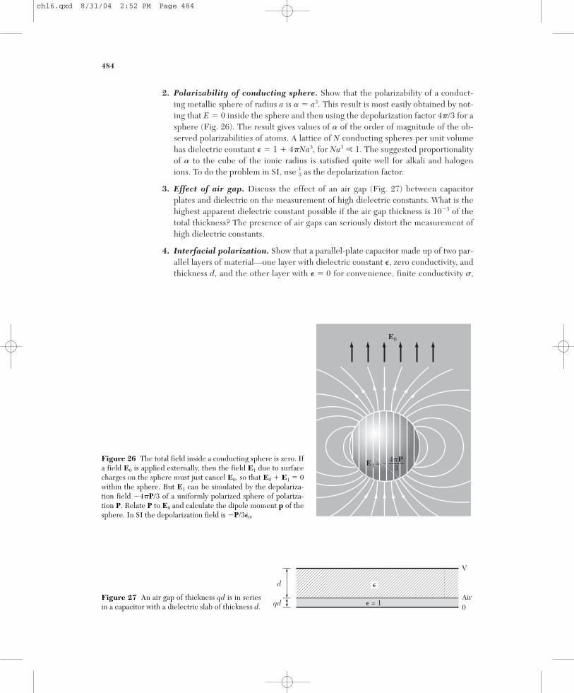
2. Polarizability of conducting sphere. Show that the polarizability of a conduct-ing metallic sphere of radius a is � � a3. This result is most easily obtained by not-ing that E � 0 inside the sphere and then using the depolarization factor 4�/3 for asphere (Fig. 26). The result gives values of � of the order of magnitude of the ob-served polarizabilities of atoms. A lattice of N conducting spheres per unit volumehas dielectric constant � � 1 � 4�Na3, for Na3 1. The suggested proportionalityof � to the cube of the ionic radius is satisfied quite well for alkali and halogenions. To do the problem in SI, use as the depolarization factor.
3. Effect of air gap. Discuss the effect of an air gap (Fig. 27) between capacitorplates and dielectric on the measurement of high dielectric constants. What is thehighest apparent dielectric constant possible if the air gap thickness is 10�3 of thetotal thickness? The presence of air gaps can seriously distort the measurement ofhigh dielectric constants.
4. Interfacial polarization. Show that a parallel-plate capacitor made up of two par-allel layers of material—one layer with dielectric constant �, zero conductivity, andthickness d, and the other layer with � � 0 for convenience, finite conductivity ,
13
484
4�P3
E1 = –
E0
Figure 26 The total field inside a conducting sphere is zero. Ifa field E0 is applied externally, then the field E1 due to surfacecharges on the sphere must just cancel E0, so that E0 � E1 � 0within the sphere. But E1 can be simulated by the depolariza-tion field �4�P/3 of a uniformly polarized sphere of polariza-tion P. Relate P to E0 and calculate the dipole moment p of thesphere. In SI the depolarization field is �P/3�0.
V
Air0� = 1
d
qd
�
Figure 27 An air gap of thickness qd is in seriesin a capacitor with a dielectric slab of thickness d.
ch16.qxd 8/31/04 2:52 PM Page 484

and thickness qd—behaves as if the space between the condenser plates werefilled with a homogeneous dielectric with dielectric constant
where is the angular frequency. Values of �eff as high as 104 or 105 caused largelyby this Maxwell-Wagner mechanism are sometimes found, but the high values arealways accompanied by large ac losses.
5. Polarization of sphere. A sphere of dielectric constant � is placed in a uniform ex-ternal electric field E0. (a) What is the volume average electric field E in the sphere?(b) Show that the polarization in the sphere is P � �E0 /[1 � (4��/3)], where � �
(� � 1)/4�. Hint: You do not need to calculate Eloc in this problem; in fact it is con-fusing to do so, because � and � are defined so that P � �E. We require E0 to be un-changed by insertion of the sphere. We can produce a fixed E0 by placing positivecharges on one thin plate of an insulator and negative charges on an opposite plate. Ifthe plates are always far from the sphere, the field of the plates will remain un-changed when the sphere is inserted between them. The results above are in CGS.
6. Ferroelectric criterion for atoms. Consider a system of two neutral atoms sepa-rated by a fixed distance a, each atom having a polarizability �. Find the relationbetween a and � for such a system to be ferroelectric. Hint: The dipolar field isstrongest along the axis of the dipole.
7. Saturation polarization at Curie point. In a first-order transition the equilibriumcondition (43) with T set equal to Tc gives one equation for the polarization Ps(Tc). A further condition at the Curie point is that (Ps, Tc) � (0, Tc). (a) Combiningthese two conditions, show that P2
s(Tc) � 3|g4|/4g6. (b) Using this result, show thatTc � T0 � 3g2
4 /16�g6.
8. Dielectric constant below transition temperature. In terms of the parametersin the Landau free energy expansion, show that for a second-order phase transitionthe dielectric constant below the transition temperature is
This result may be compared with (44) above the transition.
9. Soft modes and lattice transformations. Sketch a monatomic linear lattice oflattice constant a. (a) Add to each of six atoms a vector to indicate the direction ofthe displacement at a given time caused by a longitudinal phonon with wavevectorat the zone boundary. (b) Sketch the crystal structure that results if this zoneboundary phonon becomes unstable ( → 0) as the crystal is cooled through Tc. (c) Sketch on one graph the essential aspects of the longitudinal phonon dispersionrelation for the monatomic lattice at T well above Tc and at T � Tc. Add to thegraph the same information for phonons in the new structure at T well below Tc.
10. Ferroelectric linear array. Consider a line of atoms of polarizability � and sepa-ration a. Show that the array can polarize spontaneously if � a3/4�n�3, wherethe sum is over all positive integers and is given in tables as 1.202. . . .
� � 1 � 4��P/E � 1 � 2�/�(Tc � T) .
FF
�eff � �(1 � q)
1 � (i� q/4�) ,
16 Dielectrics and Ferroelectrics 485
ch16.qxd 8/31/04 2:52 PM Page 485

ch16.qxd 8/31/04 2:52 PM Page 486


![Ferroelectrics - DBK Groupdbkgroup.org/Papers/kell_ast_wff_ferro1_88.pdf · Downloaded By: [The University of Manchester] At: 16:47 28 February 2007 Ferroelectrics, 1988, Vol. 86,](https://static.fdocuments.us/doc/165x107/5b664ebe7f8b9a2f5c8cc6d4/ferroelectrics-dbk-downloaded-by-the-university-of-manchester-at-1647.jpg)
