Die design and process optimization of die cast V6 engine ... · PDF fileVol. 2 No. 1 Die...
7
Vol. 2 No. 1, Feb. 2005 CHINA FOUNDRY Die design and process optimization of die cast V6 engine blocks *Henry HU 1 , Yeouli CHU 2 , Patrick CHENG 2 (1. Department of Mechanical, Automotive & Materials Engineering University of Windsor; 2. Research and Development Ryobi Die Casting (USA), Inc.) Abstract: The use of aluminum, particularly for engine blocks, has grown considerably in the past ten years, and continues to rise in the automotive industry. In order to enhance the quality and engineering functionality of die cast engine blocks, die design and processes have to be optimized. In this study, a computer simulation software, MAGMAsoft, as an advanced tool for optimizing die design and casting process, was employed to virtually visualize cavity filling and patterns of a V6 engine block. The original die design and process was simulated first to establish a baseline. A reality check was used to verify the predicted results. Then, the die modification with a different runner system was made by using a CAD software, Unigraphics (UG). The simulation on combinations of the modified die design and revised process was performed to examine the effect of die modification and process change on flow filling of V6 engine blocks. The simulated prediction indicates that the enhancement of cavity filling due to the die and process modification minimizes the occurrence of defects during casting, and consequently improves the quality of blocks. The results of mechanical testing show a significant increase in fatigue strengths, and a moderately improvement on tensile properties for the blocks die cast with the new die design and process in comparison with those produced by the original ones. Keywords: die design; simulation; engine blocks CLC number: TG292-39 Document: A Article ID: 1672-6421 (2005)01-0021-07 1. Introduction Due to fuel economy and emission pressures, the use of aluminum continues to rise in the automotive industry. Aluminum's use in automobiles worldwide has gone from 45 kg (101 lbs) in the 1970s to more than 100 kg (225 lbs) today, and will top 150 kg (337 lbs) per vehicle by 2010. Over the past 10 years, shipments of aluminum castings increased by nearly 65%. Aluminum casting weight per vehicles is also forecast to grow to 123 kg (270 lbs) by 2011 [1] . The major impetus behind more widespread aluminum casting use has been the auto industry's fuel economy requirements, which have necessitated the trend toward lighter cars and trucks. This is because up to eight percent fuel savings or as much as 2.5 extra miles per gallon can be realized for every 10 percent reduction in weight from substituting aluminum for heavier metals. As a result, a vehicle that uses less fuel by lowering its weight with aluminum produces fewer greenhouse gas emissions. It is forecast that the use of aluminum for car and light vehicle engine block applications is expected to explode by 48% over the next 10 years. As one of Ward's 10 best engines for 1999 [2] , General Motor Corp's aluminum- intensified 3.5-liter V6 engines was introduced in 1998. This paper discusses development work involved in prototyping and production of die cast aluminum blocks for V6 engines. During V6 block development, various versions of die design and process parameters were investigated. The original gating system and process design was a combination of L- runner and slow filling as shown in Fig.1. The disadvantages of L-runner design and slow filling process during the production have been found, which result in various defects such as Siamese cracks, cold shuts and porosity-related leak. In order to overcome the disadvantages of the old die and process design, extensive computer simulation work was conducted to analyze the cavity filling sequences and temperature distribution with different gate designs and process parameters. The goal has been to prevent and minimize the occurrence of defects, and enhance the quality and engineering functionality of V6 blocks. A flow and thermal modeling software, MAGMAsoft [3-4] , was employed for the simulation work while a CAD software, Unigraphics, was used for the modification of die design. In this paper, the simulation results for the cavity filling of the aluminum V6 blocks are presented. The numerical simulation was validated by a reality check with a partial filled V6 block. The merits and demerits of different gate design and process parameters are discussed. The verification of simulation was carried out by mechanically *Henry HU: Associate Prof., research is focused on transport phenomena and mechanisms of solidification, phase transformation and dissolution kinetics. E-mail: [email protected] [Received date] 2004-09-01; [Accepted date] 2004-12-04
Transcript of Die design and process optimization of die cast V6 engine ... · PDF fileVol. 2 No. 1 Die...

Vol. 2 No. 1, Feb. 2005 CHINA FOUNDRY
Die design and process optimization of die cast V6engine blocks
*Henry HU1, Yeouli CHU2, Patrick CHENG2
(1. Department of Mechanical, Automotive & Materials Engineering University of Windsor; 2. Research and DevelopmentRyobi Die Casting (USA), Inc.)
Abstract: The use of aluminum, particularly for engine blocks, has grown considerably in the past ten years, andcontinues to rise in the automotive industry. In order to enhance the quality and engineering functionality of die castengine blocks, die design and processes have to be optimized. In this study, a computer simulation software,MAGMAsoft, as an advanced tool for optimizing die design and casting process, was employed to virtually visualize cavityfilling and patterns of a V6 engine block. The original die design and process was simulated first to establish a baseline.A reality check was used to verify the predicted results. Then, the die modification with a different runner system wasmade by using a CAD software, Unigraphics (UG). The simulation on combinations of the modified die design andrevised process was performed to examine the effect of die modification and process change on flow filling of V6 engineblocks. The simulated prediction indicates that the enhancement of cavity filling due to the die and process modificationminimizes the occurrence of defects during casting, and consequently improves the quality of blocks. The results ofmechanical testing show a significant increase in fatigue strengths, and a moderately improvement on tensile propertiesfor the blocks die cast with the new die design and process in comparison with those produced by the original ones.
Keywords: die design; simulation; engine blocks
CLC number: TG292-39 Document: A Article ID: 1672-6421 (2005)01-0021-07
1. IntroductionDue to fuel economy and emission pressures, the use of
aluminum continues to rise in the automotive industry.
Aluminum's use in automobiles worldwide has gone from
45 kg (101 lbs) in the 1970s to more than 100 kg (225 lbs)
today, and will top 150 kg (337 lbs) per vehicle by 2010.
Over the past 10 years, shipments of aluminum castings
increased by nearly 65%. Aluminum casting weight per
vehicles is also forecast to grow to 123 kg (270 lbs) by
2011 [1]. The major impetus behind more widespread
aluminum casting use has been the auto industry's fuel
economy requirements, which have necessitated the trend
toward lighter cars and trucks. This is because up to eight
percent fuel savings or as much as 2.5 extra miles per
gallon can be realized for every 10 percent reduction in
weight from substituting aluminum for heavier metals. As
a result, a vehicle that uses less fuel by lowering its weight
with aluminum produces fewer greenhouse gas emissions.
It is forecast that the use of aluminum for car and light
vehicle engine block applications is expected to explode
by 48% over the next 10 years. As one of Ward's 10 best
engines for 1999 [2], General Motor Corp's aluminum-
intensified 3.5-liter V6 engines was introduced in 1998.
This paper discusses development work involved in
prototyping and production of die cast aluminum blocks
for V6 engines. During V6 block development, various
versions of die design and process parameters were
investigated. The original gating system and process
design was a combination of L- runner and slow filling as
shown in Fig.1. The disadvantages of L-runner design and
slow filling process during the production have been
found, which result in various defects such as Siamese
cracks, cold shuts and porosity-related leak.
In order to overcome the disadvantages of the old die
and process design, extensive computer simulation work
was conducted to analyze the cavity filling sequences and
temperature distribution with different gate designs and
process parameters. The goal has been to prevent and
minimize the occurrence of defects, and enhance the
quality and engineering functionality of V6 blocks. A flow
and thermal modeling software, MAGMAsoft [3-4], was
employed for the simulation work while a CAD software,
Unigraphics, was used for the modification of die design.
In this paper, the simulation results for the cavity filling of
the aluminum V6 blocks are presented. The numerical
simulation was validated by a reality check with a partial
filled V6 block. The merits and demerits of different gate
design and process parameters are discussed. The
verification of simulation was carried out by mechanically
*Henry HU: Associate Prof., research is focused on transportphenomena and mechanisms of solidification,phase transformation and dissolution kinetics.E-mail: [email protected]
[Received date] 2004-09-01; [Accepted date] 2004-12-04

CHINA FOUNDRY Feb. 2005
testing specimens sampled from the bulkhead region of
blocks to determine their fatigue strengths and tensile
properties.
2. Simulation and mechanical testingprocedures
2.1 Geometry modeling and simulation
Simulation of the cavity filling and solidification
process requires the geometry input of the casting and the
die, including the internal cooling system. Fig.2 shows
the solid CAD model created with UG of Unigraphics
solution Inc. A rapid prototype interface of UG was used
to convert the geometry information of the solid model
into a STL file. The preprocessor module of MAGMAsoft
reads the STL file as a geometry input into the software.
Following the establishment of the geometry of the full
casting system, the geometry was meshed automatically
by the enmeshment module prior to the simulation. The
complexity of V6 block casting required the enmeshment
of about 10 million elements. Once the meshed geometry
has been established, the process information of castings,
the thermophysical properties of the cast metal (Al 380),
and initial and boundary conditions have to be defined in
order to run the simulation. The thermophysical properties
of the alloy for the blocks (Al 380) are available in the
database module of MAGMAsoft. The boundary
conditions used for simulation are listed in Table 1. The
simulation was carried out on a dual-processor NT station
with a speed of 500 MHz and a SDRAM of 1 gigabits.
Fig.1 Die cast aluminum V6 block with a L-runner

Vol. 2 No. 1 Die design and process optimization of die cast V6 engine blocks
system designs, multiple specimens fatigue tests were
carried out at several specific stress levels so that a series
of statistically valid data sets could be obtained. The
fatigue strength of the tested engine blocks was
determined by using a staircase method [5].
Fiq.2 Geometry model for computer simulation
Table 1 Initial and boundary conditions used for computer
simulation
2.2 Mechanical testing
The mechanical properties of engine blocks die cast
with two different gating system designs and the process
parameters indicated in Table 1 were evaluated by tensile
and fatigue tests. As illustrated in Fig.3, specimens for
tensile and fatigue tests were sectioned, machined from
bulkheads of engine blocks with reference to Fig.1(a). All
the specimens for mechanical testing are prepared
according to ASTM E-8. The tensile specimens were
cylindrical, with an overall length of 7.62 cm, a gauge
length of 2.54 cm, and a gauge diameter of 0.635 cm. The
fatigue specimens were also cylindrical, with an overall
length of 8.89 cm, a gauge length of 2.54 cm, and a gauge
diameter of 0.635 cm. All of the tensile and fatigue tests
in compliance with ASTM E8 and E466 were performed
on a hydraulically-actuated test machine equipped with a
computer data acquisition system. The tests were uniaxial,
conducted at ambient temperature in the laboratory air.
The tensile properties, including 0.2% yield strength (YS)
and ultimate tensile strength (UTS), to failure (Ef), were
obtained based on the average of twenty tests. The fatigue
tests were high cycle, used a frequency of 90 Hz, and had
a stress ratio, R, of-1. For one of the process and gate
Fig.3 Sectioning of bulkhead for tensile and fatigue specimens
3. Results and discussion
3.1 Reality check
The accuracy of predicted results is always a concern of
die casting process engineers and experienced users of
computer simulation. The precision of computer output is
dependent primarily on the accuracy of input information.
In order to verify the correctness of the input data and
boundary conditions, a comparison was made between the
predicted last fill region and a not fully filled casting. Fig.
4 illustrates the computed result of a V6 block casting
with 70% of the total volume filled. A not fully filled V6
block was intentionally cast as shown in Fig.5. By
comparing Fig.4 and Fig.5, it is seen that the computer
simulation result is in good agreement with the
experimental result.
Fig.4 Computer Simulation showing a V6 block with
70% of the cavity filled
CHINA FOUNDRY Feb. 2005
Fig.5 A partially filled die cast V6 block
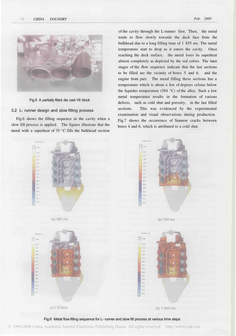
3.2 L- runner design and slow filling process
Fig.6 shows the filling sequence in the cavity when a
slow fill process is applied. The figures illustrate that the
metal with a superheat of 35 °C fills the bulkhead section
of the cavity through the L-runner first. Then, the metal
tends to flow slowly towards the deck face from the
bulkhead due to a long filling time of 1 855 ms. The metal
temperature start to drop as it enters the cavity. Once
reaching the deck surface, the metal loses its superheat
almost completely as depicted by the red colors. The later
stages of the flow sequence indicate that the last sections
to be filled are the vicinity of bores 5 and 6, and the
engine front part. The metal filling these sections has a
temperature which is about a few of degrees celsius below
the liquidus temperature (584 °C) of the alloy. Such a low
metal temperature results in the formation of various
defects, such as cold shut and porosity, in the last filled
sections. This was evidenced by the experimental
examination and visual observations during production.
Fig.7 shows the occurrence of Siamese cracks between
bores 4 and 6, which is attributed to a cold shut.
Fig.6 Metal flow filling sequence for L- runner and slow fill process at various time steps

Vol. 2 No. 1 Die design and process optimization of die cast V6 engine blocks
Fig.7 Photographs showing a Siamese crack caused by a cold shut
(a) Overview of a sectioned area between bores 4 and 6(b) Enlarged view of Siamese area where a crack is
present due to cold shut
3.3 J- runner modification and fast filling process
The first modification was attempted to increase the
fast shot speed and decrease the cavity fill time. The
improvement, however, on reducing the occurrence of
defects such as cold shuts and lack of fill is not so
significant. Following the first attempt, it was considered
that the geometry of the gating and running system of V6
blocks must be adapted in order to considerably reduce
the fill time required for the vicinity of bores 5 and 6,
where most of defects forms. Based on such a
consideration, it was decided to turn overflow 1 as
indicated in Fig.8 with reference to Fig. 1 into a gate
without suffering a large cost penalty resulting from die
modification. A new geometry model with a J-runner
system as illustrated in Fig.8 was created, and transferred
into MAGMAsoft. Actually, the following three aspects of
the die geometry and process have been modified to
optimize flow into the last filled section of the V6
casting:
The extra gates generated from the conversion of
overflow reduce the flow distance to the section of the
helper side.
The reduction in gate thicknesses decreases the total
gate area and significant increases the gate velocity.
The increase in the fast shot speed lowers the total fill
time considerably.
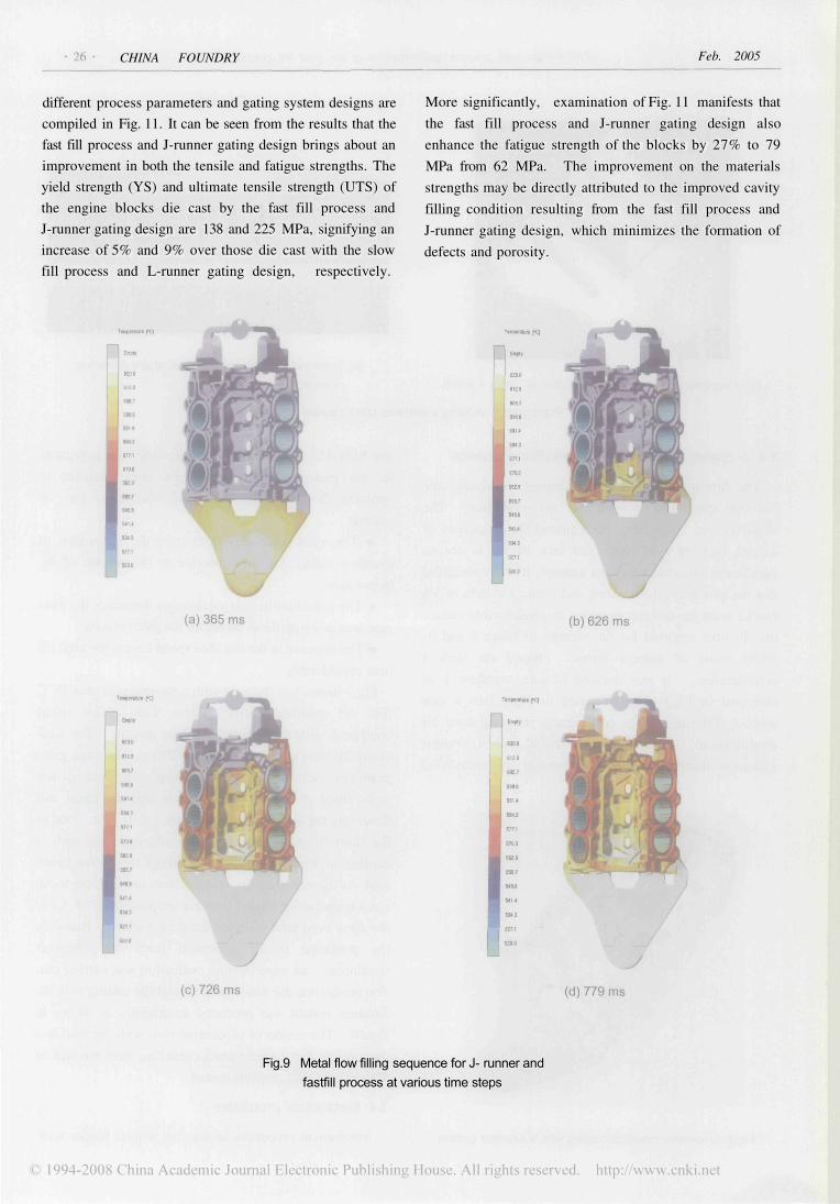
Fig.9 shows that the melt with a superheat of also 35 °C
fills the modified gating system with a fast speed
compared with that of the previous design. The total
cavity fill time in this case is only 829 ms. The extra gates
enable the vicinity of bores 2 and 6 up to the deck surface
to be filled at an early time despite that the metal still
flows into the bulkhead section of the cavity first. Due to
the short fill time and high gate velocity, the melt is
capable of keeping its fluidity without losing too much
heat. As illustrated by the orange colors in Fig.9, the metal
has a temperature around liquidus temperature (584 °C) of
the alloy even after reaching the deck surface. Based on
the predicted results generated from the computer
simulation, an experimental evaluation was carried out.
The production die was modified, and the casting with the
J-runner system was produced accordingly as shown in
Fig. 10. The results of production runs with the modified
die indicate that Siamese cracks resulting from the lack of
fill and cold shuts are minimized.
3.4 Mechanical properties
Mechanical properties of die cast engine blocks withFig.8 Geometry model of casting with a J-runner system
CHINA FOUNDRY Feb. 2005
different process parameters and gating system designs are
compiled in Fig. 11. It can be seen from the results that the
fast fill process and J-runner gating design brings about an
improvement in both the tensile and fatigue strengths. The
yield strength (YS) and ultimate tensile strength (UTS) of
the engine blocks die cast by the fast fill process and
J-runner gating design are 138 and 225 MPa, signifying an
increase of 5% and 9% over those die cast with the slow
fill process and L-runner gating design, respectively.
More significantly, examination of Fig. 11 manifests that
the fast fill process and J-runner gating design also
enhance the fatigue strength of the blocks by 27% to 79
MPa from 62 MPa. The improvement on the materials
strengths may be directly attributed to the improved cavity
filling condition resulting from the fast fill process and
J-runner gating design, which minimizes the formation of
defects and porosity.
Fig.9 Metal flow filling sequence for J- runner and
fastfill process at various time steps

Vol. 2 No. 1 Die design and process optimization of die cast V6 engine blocks
Fig.10 Die cast aluminum V6 block with a J-runner system
Fig.11 Effect of process and gate design on mecha-nical properties of die cast V6 engine blocks
4. Conclusions(1) The study concludes that the application of com-
puter simulation to die design is especially helpful in
optimizing cavity filling and minimizing the defect
formation during die casting production. As a result, the
quality and engineering properties, such as fatigue and
tensile strengths, of die cast engine blocks are enhanced.
(2) The simulation enables die casting engineers to vi-
sualize the effect of the gate change and process
modification on flow filling and thermal patterns. The
simulation analysis provides the engineering guidelines
that make the die and process change successful in a
cost-effective manner during this study.
AcknowledgementsThe authors would like to express their appreciations to
the Natural Sciences and Engineering Research Council of
Canada, Ryobi die casting (USA), Inc., GM Powertrain
Division, and University of Windsor for supporting this
work.
References[1] K. H. Kirgin and M. J. Lessiter. U.S. Casting Demand and
Supply-2002. Engineering Casting Solution. Winter Issue, 2002,25-28
[2] General Motors Corp.'s 3.5L Twin Cam V6. Ward's AutoWorld, 2000, 1:44
[3] D. M. Lipinski, W. Schaefer and S. Andersen. Modeling ofCombined Heat and Fluid Flow for Determination of FillingSequence for Real Complex Shaped Casting. Modeling ofCasting, Welding and Advanced Solidification Processes, ed.M. Rappaz, M. R. Ozgu and K. W. Mahin , TMS, 1991, 771-777
[4] D. M. Lipinski, W. Schaefer and E. Flender. Numerical Modellingof the Filling Sequence and Solidification of Castings. Modelingof Casting, Welding and Advanced Solidification Processes, ed.T.Piwonka, V. Voller, L. Katgerman, TMS, 1993, 389-397.
[5] J. A. Collins. Failure of Materials in Mechanical Design. JohnWiley & Sons. New York: 1981