Dibond Fabrication Manual - GraphicDisplay USA Fabrication Manual...Knife Cutting Saw Cutting...
48
The Aluminum Composite Material (ACM) Family 1 of 48 Fabrication Manual May 2011 3A Composites
Transcript of Dibond Fabrication Manual - GraphicDisplay USA Fabrication Manual...Knife Cutting Saw Cutting...
The Aluminum Composite Material (ACM) Family
1 of 48
FabricationManual
May 2011
3A Composites
Thank you for choosing a 3A Composites product for your graphic display applications.
We have compiled this Fabrication Manual based on our Fabrication Guide, which is divided into the following sections:
Mounting
Repositioning Vinyl
Direct Digital Printing
Direct Screen Printing
Painting
Knife Cutting
Saw Cutting
Routing
Die Cutting / Punching
Embossing
Forming Curves
Appendix I: MSDS (Material Data Safety Sheet)
Appendix II: Specifications
This Fabrication Guide was created to incorporate the most common fabrication methods that are used with 3A Composites’line of graphics display products. Not all fabrication methods are compatible with each product, but this format was kept for consistency purposes. The term “the substrate” is used throughout this guide and is meant to apply to all members ofthe substrate family unless noted otherwise. Those fabrication methods that do not apply to a certain product are statedwith a short explanation and a recommendation for an alternative product that fits that application method.
This manual also contains Appendix I which provides a Material Safety Data Sheet section. Appendix II includes an adhesives,fastening and storage guidelines section. Any unique product information will be contained in Appendix II. See Table ofContents. An Appendix III section lists products that can be used in conjunction with 3A Composites products. 3A Composites isnot responsible for the performance of any of these products when used independently or with any 3A Composites product.
The date of the last revision is shown on the bottom right hand corner of each page. Please make sure you have the most current version by going to GraphicDisplayUSA.com and selecting the document library.
If you have any further questions about our product or about how to use this manual, please feel free to contact us at 1-800-626-3365.
PLEASE NOTE:
TRIALING IS RECOMMENDED TO ENSURE SUITABILITY FOR THE PROPOSED APPLICATION AND FABRICATIONBEFORE FULL-SCALE COMMERCIALIZATION.
Foreword
2 of 48 May 2011Foreword
Table of Contents . . . . . . . . . . . . . . . . . . . . . . . .3
Introduction3A Composites Family of Products . . . . . . . . . . . . . . . . . . .5Choosing Your Graphic Display Board . . . . . . . . . . . . . . . .9Introduction to Dibond . . . . . . . . . . . . . . . . . . . . . . . . . . .10Why Choose Dibond? . . . . . . . . . . . . . . . . . . . . . . . . . . . .10Dibond Application & Fabrication Guides . . . . . . . . . . . .11
Section I: MountingMounting — General Notes . . . . . . . . . . . . . . . . . . . . . . .12A Note on Archival Mounting (Conservation Framing) . . .12Methods for Mounting . . . . . . . . . . . . . . . . . . . . . . . . . . .12Surface Preparation . . . . . . . . . . . . . . . . . . . . . . . . . . . . . .12Other Considerations . . . . . . . . . . . . . . . . . . . . . . . . . . . . .12Hot Mounting — General Notes . . . . . . . . . . . . . . . . . . .13Cold Mounting — General Notes . . . . . . . . . . . . . . . . . .13
Getting Good Adhesion . . . . . . . . . . . . . . . . . . . . . . . . .13Demounting Bad Mounts . . . . . . . . . . . . . . . . . . . . . . .13Avoiding Wrinkles and Surface Blemishes . . . . . . . . . .13Clear Overlays . . . . . . . . . . . . . . . . . . . . . . . . . . . . . . . .13
Cold Mounting Procedures . . . . . . . . . . . . . . . . . . . . . . . .14Cold Mounting by Hand Using Transfer Adhesive . . . .14Cold Mounting by Hand or Press Using Spray
Adhesive . . . . . . . . . . . . . . . . . . . . . . . . . . . . . . . . . . .14Cold Mounting by Roller Laminator with an
Adhesive-backed Graphic . . . . . . . . . . . . . . . . . . . . . .14A Note on Cold Mounting Non-Porous Graphics . . . . .15A Note on Cold Mounting Porous Graphics . . . . . . . . .15A Note on Cold Mounting with Pressure
Sensitive Tapes . . . . . . . . . . . . . . . . . . . . . . . . . . . . . .15Troubleshooting Chart Using Cold Mounting Presses . . .16
Section II: Repositioning VinylVinyl — General Notes . . . . . . . . . . . . . . . . . . . . . . . . . . .17Surface Preparation . . . . . . . . . . . . . . . . . . . . . . . . . . . . . .17Repositioning the Vinyl . . . . . . . . . . . . . . . . . . . . . . . . . . .17
Section III: Direct Digital PrintingDirect Digital Printing — General Notes . . . . . . . . . . . . 18Surface Preparation . . . . . . . . . . . . . . . . . . . . . . . . . . . . . .18Suitable Inks . . . . . . . . . . . . . . . . . . . . . . . . . . . . . . . . . . .18
Section IV: Direct Screen PrintingDirect Screen Printing — General Notes . . . . . . . . . . . . .19Surface Preparation . . . . . . . . . . . . . . . . . . . . . . . . . . . . . .19Suitable Inks . . . . . . . . . . . . . . . . . . . . . . . . . . . . . . . . . . .19Ink Curing . . . . . . . . . . . . . . . . . . . . . . . . . . . . . . . . . . . . . .19
Section V: PaintingPainting — General Notes . . . . . . . . . . . . . . . . . . . . . . . .20Surface Preparation . . . . . . . . . . . . . . . . . . . . . . . . . . . . . .20Suitable Paints . . . . . . . . . . . . . . . . . . . . . . . . . . . . . . . . .20Adhesion Test . . . . . . . . . . . . . . . . . . . . . . . . . . . . . . . . . .20Application . . . . . . . . . . . . . . . . . . . . . . . . . . . . . . . . . . . .20Drying . . . . . . . . . . . . . . . . . . . . . . . . . . . . . . . . . . . . . . . .20A Note on Post-Painting . . . . . . . . . . . . . . . . . . . . . . . . . .21
Section VI: CuttingCutting — General Notes . . . . . . . . . . . . . . . . . . . . . . . . .22
Knife CuttingKnife Cutting . . . . . . . . . . . . . . . . . . . . . . . . . . . . . . . . .22
ShearingShearing . . . . . . . . . . . . . . . . . . . . . . . . . . . . . . . . . . . .22
Saw CuttingTable Saws . . . . . . . . . . . . . . . . . . . . . . . . . . . . . . . . . .22Panel Saws . . . . . . . . . . . . . . . . . . . . . . . . . . . . . . . . . .23Multiple Operation Rip/V-grooving Saws . . . . . . . . . . .23Portable (Circular) Saws . . . . . . . . . . . . . . . . . . . . . . . .23Reciprocating Saws . . . . . . . . . . . . . . . . . . . . . . . . . . . .23Band Saws . . . . . . . . . . . . . . . . . . . . . . . . . . . . . . . . . . .23
RoutingRouting — General Notes . . . . . . . . . . . . . . . . . . . . . .24Routing: For Bending . . . . . . . . . . . . . . . . . . . . . . . . . . .24Small Radius Bending (By Routing) . . . . . . . . . . . . . . .25Making Corners . . . . . . . . . . . . . . . . . . . . . . . . . . . . . . .26Common 90° V-Routed Corner . . . . . . . . . . . . . . . . . . .26Multiple 90° Corners . . . . . . . . . . . . . . . . . . . . . . . . . . .27135° Profile . . . . . . . . . . . . . . . . . . . . . . . . . . . . . . . . . .2790° Corner with Sawed Relief Cuts . . . . . . . . . . . . . . .2890° V-Routed and Trimmed . . . . . . . . . . . . . . . . . . . . . .28Flat Routed Corner . . . . . . . . . . . . . . . . . . . . . . . . . . . .29Flat Rout Distorted to Eliminate “Bumps” in
Rout and Return Curved Corner . . . . . . . . . . . . . . . . .29Flat Rout Used to Make a “Hem and Cope” . . . . . . . . .30
Die Cutting / PunchingDie Cutting/Punching . . . . . . . . . . . . . . . . . . . . . . . . . .31A Note on Punching . . . . . . . . . . . . . . . . . . . . . . . . . . .31Steel Rule Die Cutting Process . . . . . . . . . . . . . . . . . ..31
Section VII: EmbossingEmbossing . . . . . . . . . . . . . . . . . . . . . . . . . . . . . . . . . . . . .31
Table of Contents
3 of 48 May 2011Table of Contents
(Continued on next page)
Table of Contents
4 of 48 May 2011Table of Contents
Section VIII: Forming CurvesForming Curves — General Notes . . . . . . . . . . . . . . . . . .32Curving Through Cold Forming . . . . . . . . . . . . . . . . . . . . .32
Pyramid Roller . . . . . . . . . . . . . . . . . . . . . . . . . . . . . . . .32Press Brake . . . . . . . . . . . . . . . . . . . . . . . . . . . . . . . . . .32Bending Over a Clamped Pipe . . . . . . . . . . . . . . . . . . .32
Appendix I: MSDSMaterial Safety Data Sheet . . . . . . . . . . . . . . . . . . . . . . .33
Appendix II: SpecificationsAdhesivesAdhesive Used with Dibond Material . . . . . . . . . . . . . . .36Adhesive Research Results . . . . . . . . . . . . . . . . . . . . . . . .361-Part Silicones, Adhesives and Sealants . . . . . . . . . . . .361-Part Silicones or Urethane Adhesives/Sealants Requiring a Primer . . . . . . . . . . . . . . . . . . . . . . . . . . . . . . .372-Part Methacrylate, Urethane, and Epoxy Adhesives . . .37Synthetic Rubber and 1-Part Urethane Adhesives . . . . . .37Acrylic Foam Tape . . . . . . . . . . . . . . . . . . . . . . . . . . . . . . .37Summary . . . . . . . . . . . . . . . . . . . . . . . . . . . . . . . . . . . . . .37
FasteningJoining Dibond Material . . . . . . . . . . . . . . . . . . . . . . . . . .38Threaded Fasteners . . . . . . . . . . . . . . . . . . . . . . . . . . . . . .38Rivets . . . . . . . . . . . . . . . . . . . . . . . . . . . . . . . . . . . . . . . . .38Adhesives . . . . . . . . . . . . . . . . . . . . . . . . . . . . . . . . . . . . .38Tapes . . . . . . . . . . . . . . . . . . . . . . . . . . . . . . . . . . . . . . . . .38Concepts . . . . . . . . . . . . . . . . . . . . . . . . . . . . . . . . . . . . . .39Drilling . . . . . . . . . . . . . . . . . . . . . . . . . . . . . . . . . . . . . . . .41
Thermal Expansion . . . . . . . . . . . . . . . . . . . . . . . . .41
Storage Guidelines . . . . . . . . . . . . . . . . . . . . . . . . .41
Engineering Specifications . . . . . . . . . . . . . . . .42
Evaluated Post-Paint Finishes Chart . . . . . .43
Screen Printing Inks Chart . . . . . . . . . . . . . . . . .44
UL Certificate of Compliance . . . . . . . . . . . . . .45
Dibond® Physical ProductSpecifications Chart . . . . . . . . . . . . . . . . . . . . . . .46
e-panelTM Physical ProductSpecifications Chart . . . . . . . . . . . . . . . . . . . . . . .47
3A Composites Family of Products
5 of 48 May 20113A Composites Family of Products
CHOOSING YOUR GRAPHIC DISPLAY BOARD IS EASIER THAN EVER.3A Composites offers a legendary array of brands for the graphic display market, including: fluted polypropylene sheets,paper-faced foam boards, expanded plastic boards, polystyrene foam boards with wood-fiber veneers, and aluminum compositepanels. All of our brands offer unique competitive advantages and outstanding capabilities for designers and fabricators seekingto create signage, displays and graphic applications on an epic scale.
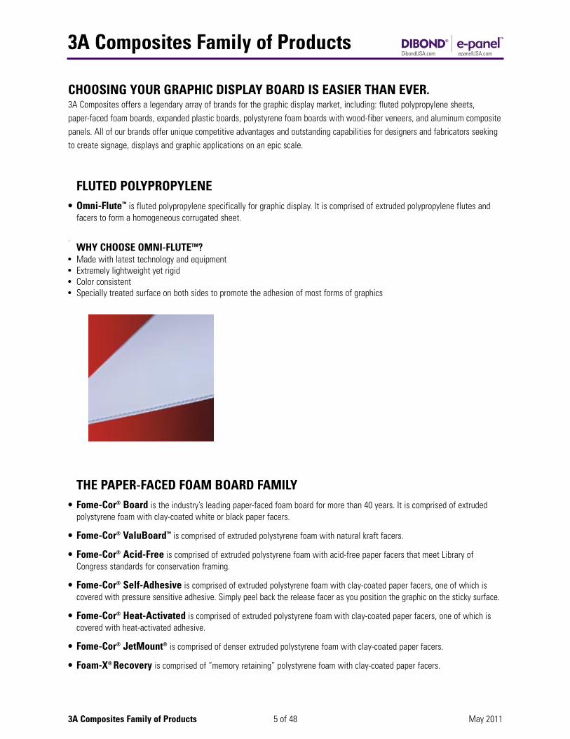
FLUTED POLYPROPYLENE• Omni-Flute™ is fluted polypropylene specifically for graphic display. It is comprised of extruded polypropylene flutes and
facers to form a homogeneous corrugated sheet.
.WHY CHOOSE OMNI-FLUTETM?
• Made with latest technology and equipment• Extremely lightweight yet rigid• Color consistent• Specially treated surface on both sides to promote the adhesion of most forms of graphics
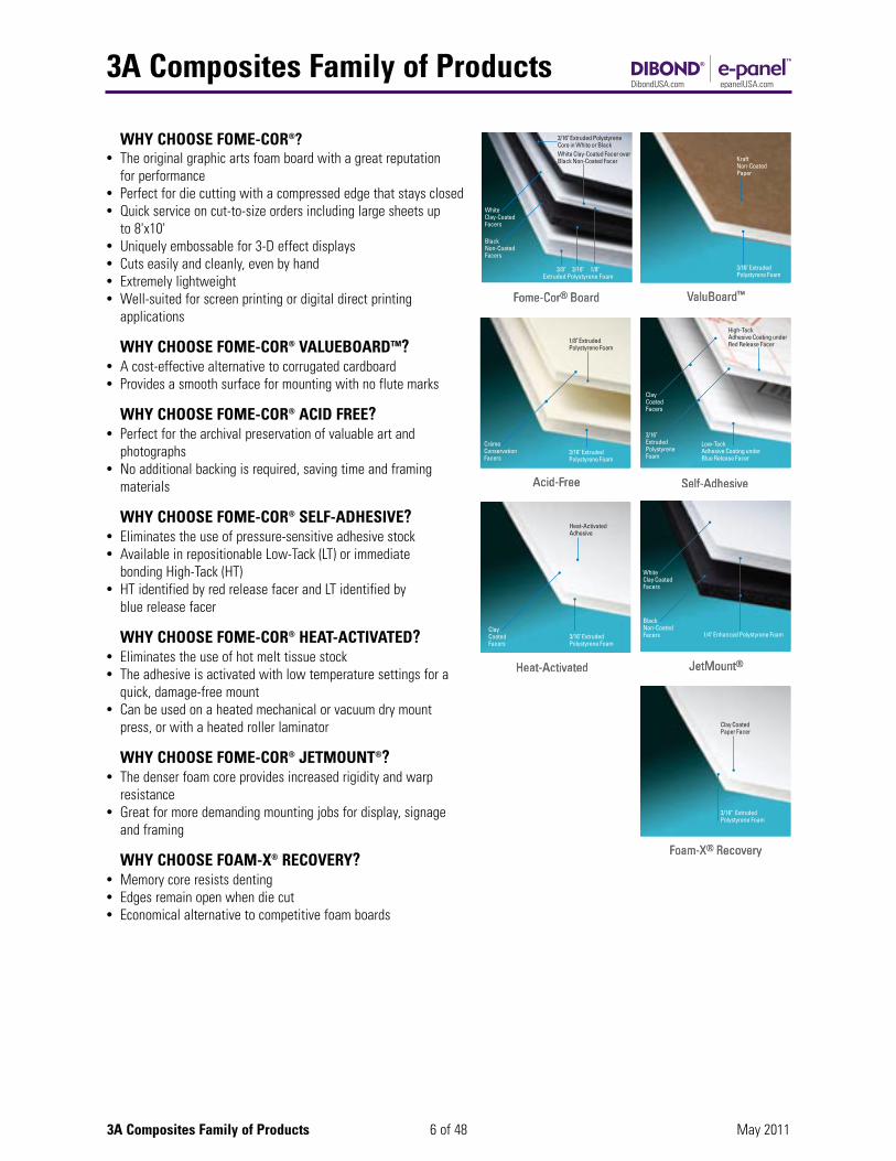
THE PAPER-FACED FOAM BOARD FAMILY• Fome-Cor® Board is the industry’s leading paper-faced foam board for more than 40 years. It is comprised of extruded
polystyrene foam with clay-coated white or black paper facers.
• Fome-Cor® ValuBoard™ is comprised of extruded polystyrene foam with natural kraft facers.
• Fome-Cor® Acid-Free is comprised of extruded polystyrene foam with acid-free paper facers that meet Library of Congress standards for conservation framing.
• Fome-Cor® Self-Adhesive is comprised of extruded polystyrene foam with clay-coated paper facers, one of which is covered with pressure sensitive adhesive. Simply peel back the release facer as you position the graphic on the sticky surface.
• Fome-Cor® Heat-Activated is comprised of extruded polystyrene foam with clay-coated paper facers, one of which is covered with heat-activated adhesive.
• Fome-Cor® JetMount® is comprised of denser extruded polystyrene foam with clay-coated paper facers.
• Foam-X® Recovery is comprised of “memory retaining” polystyrene foam with clay-coated paper facers.
3A Composites Family of Products
6 of 48 May 20113A Composites Family of Products
WHY CHOOSE FOME-COR®?• The original graphic arts foam board with a great reputation
for performance• Perfect for die cutting with a compressed edge that stays closed• Quick service on cut-to-size orders including large sheets up
to 8'x10'• Uniquely embossable for 3-D effect displays• Cuts easily and cleanly, even by hand• Extremely lightweight• Well-suited for screen printing or digital direct printing
applications
WHY CHOOSE FOME-COR® VALUEBOARDTM?• A cost-effective alternative to corrugated cardboard• Provides a smooth surface for mounting with no flute marks
WHY CHOOSE FOME-COR® ACID FREE?• Perfect for the archival preservation of valuable art and
photographs• No additional backing is required, saving time and framing
materials
WHY CHOOSE FOME-COR® SELF-ADHESIVE?• Eliminates the use of pressure-sensitive adhesive stock• Available in repositionable Low-Tack (LT) or immediate
bonding High-Tack (HT)• HT identified by red release facer and LT identified by
blue release facer
WHY CHOOSE FOME-COR® HEAT-ACTIVATED?• Eliminates the use of hot melt tissue stock• The adhesive is activated with low temperature settings for a
quick, damage-free mount• Can be used on a heated mechanical or vacuum dry mount
press, or with a heated roller laminator
WHY CHOOSE FOME-COR® JETMOUNT®?• The denser foam core provides increased rigidity and warp
resistance• Great for more demanding mounting jobs for display, signage
and framing
WHY CHOOSE FOAM-X® RECOVERY?• Memory core resists denting• Edges remain open when die cut• Economical alternative to competitive foam boards
3/16" Extruded Polystyrene Core in White or Black
White Clay-Coated Facer over Black Non-Coated Facer
3/8" 3/16" 1/8"Extruded Polystyrene Foam
WhiteClay-CoatedFacers
BlackNon-CoatedFacers
Fome-Cor® Board
draoB®roC-emoF
3/16" ExtrudedPolystyrene Foam
KraftNon-CoatedPaper
ValuBoard™
™draoBulaV
1/8" ExtrudedPolystyrene Foam
3/16" ExtrudedPolystyrene Foam
CrémeConservationFacers
Acid-Free
eerF-dicA
High-TackAdhesive Coating under Red Release Facer
Low-TackAdhesive Coating under Blue Release Facer
3/16" ExtrudedPolystyreneFoam
ClayCoatedFacers
Self-Adhesive
evisehdA-fleS
Heat-ActivatedAdhesive
3/16" ExtrudedPolystyrene Foam
ClayCoatedFacers
Heat-Activated
detavitcA-taeH
1/4" Enhanced Polystyrene Foam
WhiteClay CoatedFacers
BlackNon-CoatedFacers
JetMount®
®tt®nuoMteJ
Clay Coated Paper Facer
3/16" ExtrudedPolystyrene Foam
Foam-X® Recovery
yrevoceR®X-maoF
3A Composites Family of Products
7 of 48 May 20113A Composites Family of Products
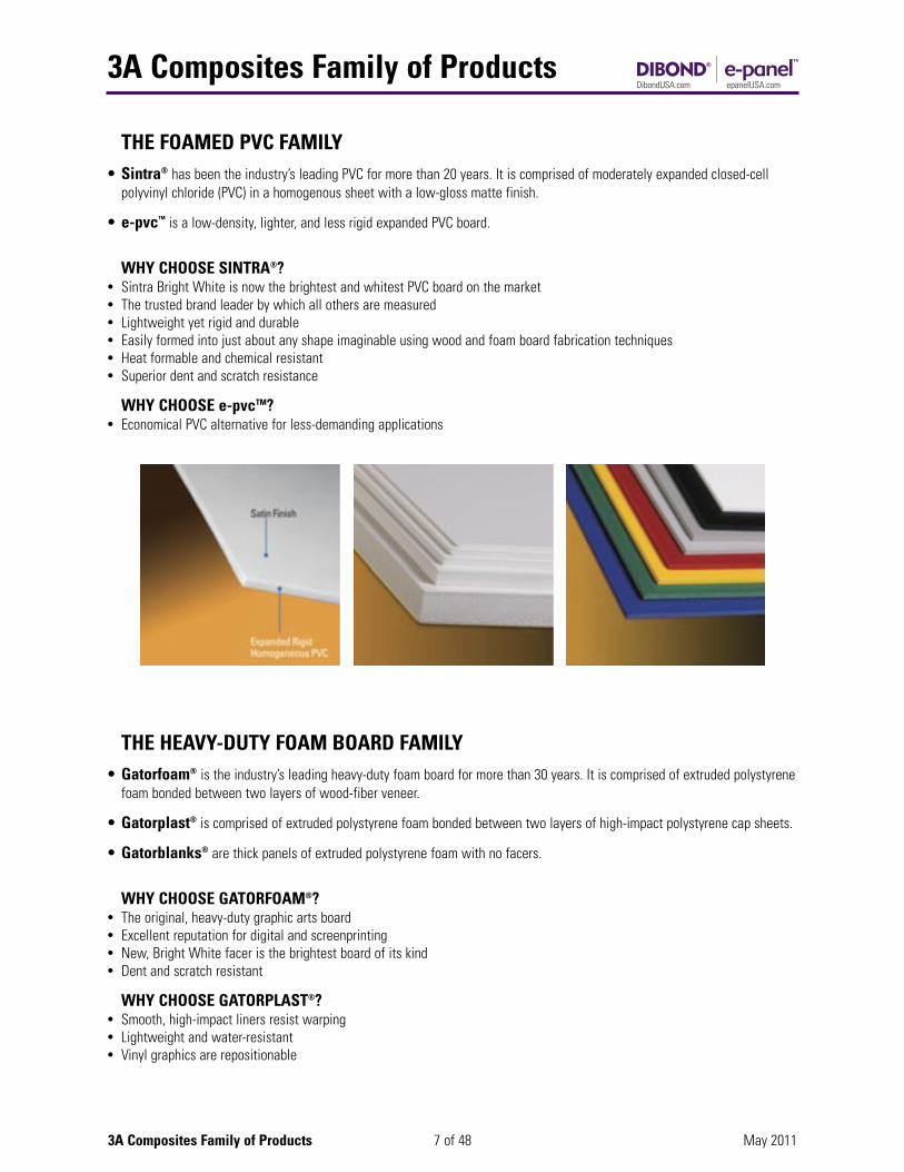
THE FOAMED PVC FAMILY• Sintra® has been the industry’s leading PVC for more than 20 years. It is comprised of moderately expanded closed-cell
polyvinyl chloride (PVC) in a homogenous sheet with a low-gloss matte finish.
• e-pvc™ is a low-density, lighter, and less rigid expanded PVC board.
WHY CHOOSE SINTRA®?• Sintra Bright White is now the brightest and whitest PVC board on the market• The trusted brand leader by which all others are measured• Lightweight yet rigid and durable• Easily formed into just about any shape imaginable using wood and foam board fabrication techniques• Heat formable and chemical resistant• Superior dent and scratch resistance
WHY CHOOSE e-pvcTM?• Economical PVC alternative for less-demanding applications
THE HEAVY-DUTY FOAM BOARD FAMILY• Gatorfoam® is the industry’s leading heavy-duty foam board for more than 30 years. It is comprised of extruded polystyrene
foam bonded between two layers of wood-fiber veneer.
• Gatorplast® is comprised of extruded polystyrene foam bonded between two layers of high-impact polystyrene cap sheets.
• Gatorblanks® are thick panels of extruded polystyrene foam with no facers.
WHY CHOOSE GATORFOAM®?• The original, heavy-duty graphic arts board• Excellent reputation for digital and screenprinting• New, Bright White facer is the brightest board of its kind• Dent and scratch resistant
WHY CHOOSE GATORPLAST®?• Smooth, high-impact liners resist warping• Lightweight and water-resistant• Vinyl graphics are repositionable
3A Composites Family of Products
8 of 48 May 20113A Composites Family of Products
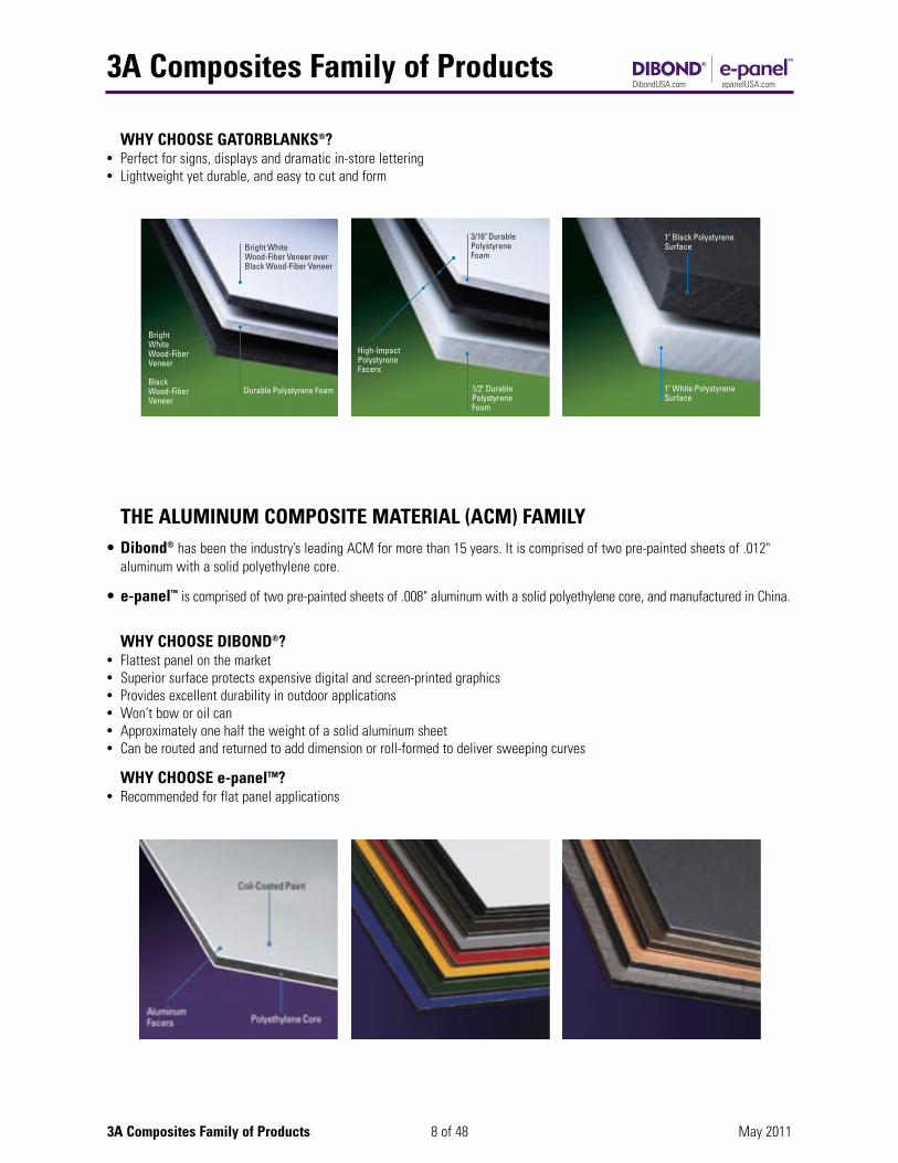
WHY CHOOSE GATORBLANKS®?• Perfect for signs, displays and dramatic in-store lettering• Lightweight yet durable, and easy to cut and form
THE ALUMINUM COMPOSITE MATERIAL (ACM) FAMILY• Dibond® has been the industry’s leading ACM for more than 15 years. It is comprised of two pre-painted sheets of .012"
aluminum with a solid polyethylene core.
• e-panel™ is comprised of two pre-painted sheets of .008" aluminum with a solid polyethylene core, and manufactured in China.
WHY CHOOSE DIBOND®?• Flattest panel on the market• Superior surface protects expensive digital and screen-printed graphics• Provides excellent durability in outdoor applications• Won’t bow or oil can• Approximately one half the weight of a solid aluminum sheet• Can be routed and returned to add dimension or roll-formed to deliver sweeping curves
WHY CHOOSE e-panelTM?• Recommended for flat panel applications
Bright WhiteWood-Fiber Veneer over Black Wood-Fiber Veneer
Bright WhiteWood-Fiber Veneer
BlackWood-Fiber Veneer
Durable Polystyrene Foam
3/16" DurablePolystyreneFoam
1/2" Durable PolystyreneFoam
High-ImpactPolystyreneFacers
1" Black PolystyreneSurface
1" White PolystyreneSurface
Choosing Your Graphic Display Board
9 of 48 May 2011Choosing Your Graphic Display Board
Mou
ntin
g
Repo
sitio
ning
Vin
yl
Dir
ect D
igita
l Pri
ntin
g
Dir
ect S
cree
n Pr
intin
g
Pain
ting
Knife
Cut
ting
Saw
Cut
ting
Rout
ing
Die
Cut
ting/
Punc
hing
Embo
ssin
g
Form
ing
Curv
es
Fabrication Guide
$
$$
PR
IC
E
RA
NG
E
1 4
$$$
2
3
3
3
3
3
3
5
5
6
6
1
1
4 5
0
Omni-FluteTM Fome-Cor® ValuBoardTM Fome-Cor® Board Foam-X® Recovery Fome-Cor® Acid-Free Fome-Cor® Self-Adhesive HT Fome-Cor® Self-Adhesive LT Fome-Cor® Heat-Activated Fome-Cor® JetMount® e-pvcTM
Sintra® Gatorblanks® Gatorplast® Gatorfoam® e-panelTM
Dibond®
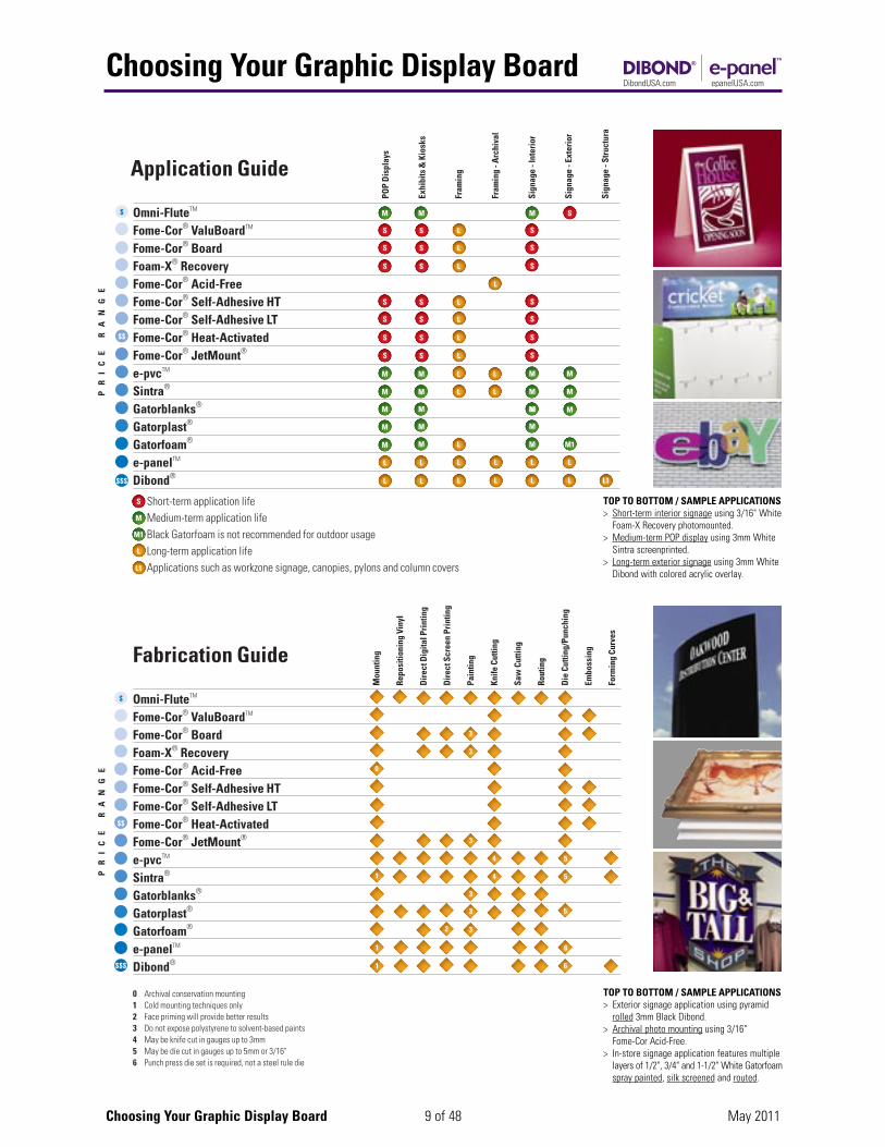
0 Archival conservation mounting1 Cold mounting techniques only2 Face priming will provide better results3 Do not expose polystyrene to solvent-based paints4 May be knife cut in gauges up to 3mm5 May be die cut in gauges up to 5mm or 3/16"6 Punch press die set is required, not a steel rule die
POP
Dis
play
s
Exhi
bits
& K
iosk
s
Fram
ing
Fram
ing
- Arc
hiva
l
Sign
age
- Int
erio
r
Sign
age
- Ext
erio
r
Sign
age
- Str
uctu
ra
Application Guide
$
$$
PR
IC
E
RA
NG
E
M M M
S S L S
S S L S
S S L S
L
S S L S
S S L S
S S L S
S S L S
M M MM M
S
M
M1
L
L1
M M M
M M M M1L
L L L L L L
L L L L L L L1$$$
M M L M
M M L M
L
L
M
M
SOmni-FluteTM Fome-Cor® ValuBoardTM
Fome-Cor® Board Foam-X® Recovery Fome-Cor® Acid-Free Fome-Cor® Self-Adhesive HT Fome-Cor® Self-Adhesive LT Fome-Cor® Heat-Activated Fome-Cor® JetMount® e-pvcTM
Sintra® Gatorblanks® Gatorplast® Gatorfoam® e-panelTM
Dibond® Short-term application life Medium-term application life Black Gatorfoam is not recommended for outdoor usage Long-term application life Applications such as workzone signage, canopies, pylons and column covers
TOP TO BOTTOM / SAMPLE APPLICATIONS> Short-term interior signage using 3/16" White
Foam-X Recovery photomounted.> Medium-term POP display using 3mm White
Sintra screenprinted.> Long-term exterior signage using 3mm White
Dibond with colored acrylic overlay.
TOP TO BOTTOM / SAMPLE APPLICATIONS> Exterior signage application using pyramid
rolled 3mm Black Dibond. > Archival photo mounting using 3/16"
Fome-Cor Acid-Free.> In-store signage application features multiple
layers of 1/2", 3/4" and 1-1/2" White Gatorfoamspray painted, silk screened and routed.
Introduction to Dibond
10 of 48 May 2011Introduction to Dibond
Dibond® material is an affordable, aluminum composite material (ACM) made of two lightweight sheets of .012" aluminum witha solid thermoplastic core. The material is intended for such applications as point of purchase displays, exhibits and kiosks,framing, archival framing, interior signage and exterior signage as well as structural signage. Additionally, Dibond’s uniqueproperties lend itself to very unique OEM industrial applications, such as engine covers, housings, etc.
The sheets are pre-painted with a polyester paint finish applied to both sides of the sheet. Dibond material is available in 2mm,3mm and 4mm thicknesses in 4' x 8', 4' x 10', and 5' x 10' sheets. The substrate is available in: White, Black, Dark Bronze, FineSilver, Hunter Red, Caution Yellow, Dark Green, Ultra Marine Blue, Brushed Silver, Brushed Bronze, Brushed Copper and BrushedStainless. Consult the Dibond website for the most current products at DibondUSA.com.
Dibond material is a UL (Underwriters Laboratories Inc.®) recognized component for electrical signage (UL 94V-0). All thicknessesof Dibond material meet the criteria for ASTM E-84, and are Class 1 or Class A materials.
Dibond material can substitute for:
• .032", .040", .050", .063", .080", .090" & .125" aluminum sheet
• MDO Board/Laminated Boards/Corrugated ACM Boards
• Thick Gauge Plastics
• Wood/Plywood Products
• Expanded PVC
Why Choose Dibond?Applications• Wall-mounted Signs• Billboards• Post & Panel Signage• Scoreboards• Column/Pole Covers• Photomounting• Fascia/Sign Bands• Routed Sign Faces• Point of Purchase Displays• Cart/Kiosk Mfg.• Transportation Applications• Screen Printing• Backing for Channel Letters• Interior Signage• Digital & Electrostatic Printing• Awnings• Custom Exhibit Booths • Murals• Custom Architectural Signage• Workzone, Traffic, Highway Signage• Illuminated & Non-illuminated Signage
Application & Fabrication Guides
11 of 48 May 2011Dibond Guides
ApplicationPO
P Di
spla
ys
Exhi
bits
& K
iosk
s
Fram
ing
Fram
ing
- Arc
hiva
l
Sign
age
- Int
erio
r
Sign
age
- Ext
erio
r
Sign
age
- Stru
ctur
al
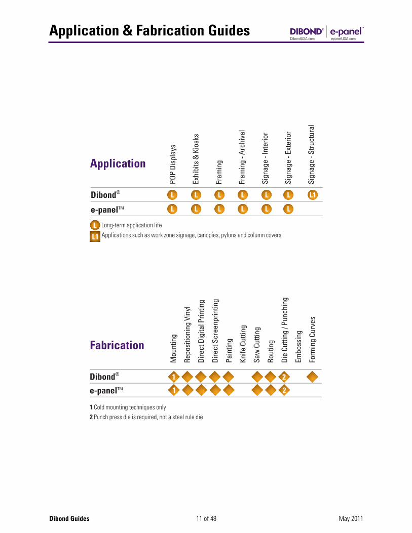
Dibond® e-panelTM
Long-term application life Applications such as work zone signage, canopies, pylons and column covers
Fabrication
Mou
ntin
g
Repo
sitio
ning
Vin
yl
Dire
ct D
igita
l Prin
ting
Dire
ct S
cree
nprin
ting
Pain
ting
Knife
Cut
ting
Saw
Cut
ting
Rout
ing
Die
Cutti
ng /
Punc
hing
Embo
ssin
g
Form
ing
Curv
es
Dibond® e-panelTM
1 Cold mounting techniques only2 Punch press die is required, not a steel rule die

Section I: Mounting
12 of 48 May 2011Section I: Mounting
Mounting – General NotesMounting, laminating and bonding are terms that are often times interchanged. For this document mounting is defined as theattachment of the graphic to the substrate. Lamination is the application of a covering (film or liquid) over the mounted item toeither protect the graphic or provide a certain appearance i.e. matte or glossy finish. Bonding also conveys affixing one thing toanother. This can involve a graphic to a substrate or one substrate to another. This document uses the term “mounting” toconvey affixing as opposed to bonding. A paper, foil, plastic or fabric graphic can be mounted to the substrate.
With regard to adhesive, mounting consideration should follow the adhesive manufacturer’s instructions. In general, determinethe minimum amount of adhesive lay down to attain the desired adhesion level. It is advisable to leave the boards for a periodof time to setup. Consult the adhesive manufacturer’s instructions to see what specific times are recommended. Please refer toAppendix I for additional adhesive information.
1. A Note on Archival Mounting (Conservation Framing)a. The substrate is not suitable for Archival Mounting.
b. Conservation or archival mounting requires the selection of materials that are pH neutral to use in conjunction with the substrate and the artwork. This includes matting material, hinges, and adhesives. Matboards, particularly those in contact with the art, should meet the Library of Congress specifications. Art must never be mounted in contact with the glass. If long-term preservation is the goal, only UV protection glass should be used. Finally, it is a good practice to seal the back of the frame with a dust cover or barrier paper.
2. Methods for Mountinga. There are a variety of methods (adhesive, pressure, etc.) for mounting a graphic to a substrate. For this document,
mounting will be broken into two groupings; hot or cold mounting, with discussion on the various methods of applying pressure.
i. Hot mounting provides a heat source to activate the adhesive. Typically, this is accomplished with a heat sourceassociated with either a vacuum press or a roller press.
ii. Cold mounting typically utilizes a spray or pressure-sensitive film or coating in combination with a roller press.
b. Printed papers, foils, and fabrics can all be mounted to the substrate provided that the proper types of adhesives are selected. Mounting can be accomplished on most standard equipment capable of applying adhesive and laminating sheets or roll stock to rigid boards.
3. Surface Preparationa. Surface should be cleaned and free of any surface contaminates (i.e. oils, dust particles, etc.) prior to commencing.
b. The substrate should be cleaned with isopropyl alcohol, using a non-colored cloth for best results. It is important not to use thinners or soaps as they may leave a film residue which can affect adhesion. Additionally, cleaners containing silicone can interfere with adhesion and are not recommended.
4. Other Considerationsa. Care should be taken when using laminate films on only one side of the mounted graphic. Moisture pickup will be
sealed on one side while the other side in not protected from moisture pickup. Bowing may occur because of moisture imbalance.
b. Additionally, care should be taken when mounting only one side with spray adhesives. As the mount cures out, tensile forces within the adhesive may cause the substrate to bow. It may be necessary to apply a counter-mount ofcomparable strength on the backside.
c. Finally, one must use the minimum amount of tension when mounting with film or pressure sensitive adhesives as too much tension will cause the substrate to bow; too little will cause the graphic to wrinkle.
Section I: Mounting
13 of 48 May 2011Section I: Mounting
Hot Mounting – General NotesThe substrate is not recommended for this fabrication method. Please see the fabrication guide on page 9 for choosing the bestrecommended product.
Cold Mounting – General Notes1. Getting Good Adhesion
a. To cold mount pressure-sensitive adhesives, you need sufficient pressure. You also must make sure that proper spacersare used. Because effective mounting depends on equal force exerted across the entire width of the substrate being mounted, the top roll must move down evenly left and right. Even contact between the top and the bottom mounting rolls is essential.
b. Adequate pressure helps squeeze out air from between the adhesive, the substrate and the print.
c. The mount obtained after 3 hours will generally allow for processing. Maximum mount is usually obtained within 24 hours after mounting.
d. To test adhesion, flex the finished mount. It should not come loose in the center.
e. Moisture can become trapped between layers of porous material (such as paper) and cause blisters. The level ofmoisture in the atmosphere should be reduced before press work. Prints may even have to be pre-dried.
f. When tacking prints to the substrate, some shops will hang a number of tacked pieces in an upside-down position untilthey are ready to pass them through. As a precaution, it is advisable not to hold them any longer than 10 minutes or the prints may absorb moisture, change in dimension and cause bubbles and wrinkles.
g. Please contact the film manufacturer for recommendations concerning the use of their respective laminating material in conjunction with the substrate as film choice is the most important consideration.
h. It is advisable to use a film with a high “green tack” strength. When using pressure sensitive films, the substrate should be at room temperature to achieve optimal results.
2. Demounting Bad Mountsa. Pressure-sensitive adhesives may be demounted if done within 5 minutes after mounting. The print will probably be
ruined, but the substrate may be reused.
b. Beyond 5 minutes, the adhesive has set and other methods will have to be used, such as a hot air gun or a hair dryer to peel off the laminate. The remaining adhesive may be taken off with isopropyl alcohol or mineral spirits.
3. Avoiding Wrinkles and Surface Blemishesa. Wrinkles can be caused by misalignment of adhesive roll, too much pressure, or unparallel rolls.
b. Small bumps, particularly visible with Cibachrome or glossy prints, are caused by trapped dirt or hardened adhesive. Good housekeeping and an ionizing static eliminator on the press are important to minimize dirt pick-up. Duringmounting, the back of the print should be checked and wiped down before it is processed. If bumps are caused by hardened adhesive (cut open to check), use a fresh roll or sheet of transfer adhesive. To prevent strikethrough, one might also consider using a print made with thicker paper (.007+).
c. Pressure roller applicators can compress the leading edge of the mounting substrate. In order to keep the leading edge from rounding as it goes through the roller, use a plastic lead or guide of the same thickness of the mounted substrate.
4. Clear Overlaysa. Clear high-gloss overlays enhance color and protect against fading indoors and outdoors. To avoid blistering, do not
use overlays, clear coatings, or sprays which contain solvents.

Section I: Mounting
14 of 48 May 2011Section I: Mounting
Cold Mounting ProceduresThere are several techniques for cold mounting to the substrate:
1. Cold Mounting by Hand Using Transfer Adhesivea. Take a sheet of transfer adhesive (both sides covered by release paper) and fold back release paper on one side
approximately 1/2" from one edge.
b. Tack on edge of print to exposed adhesive.
c. Lift the print slightly, remove the rest of the release paper and use a roller or squeegee to smooth the print onto theadhesive. The back of the print is now coated with an adhesive which is protected by release paper.
d. Before mounting to the substrate, remove excess air between print and adhesive. This is done by turning the print over so that the release paper is up and smoothing out from the center with a squeegee.
e. Now peel off approximately 1/2"–1" of release paper from upper edge and fold back.
f. Tack on to the substrate, lining up edges.
g. Using a hand roller or squeegee, closely follow the removal of the liner to eliminate bubbles caused by air entrapment. Work with a small surface at a time (approximately 12"). Continue this step until the mounting is complete.
2. Cold Mounting by Hand or Press Using Spray Adhesivea. Spray adhesive on the back of the piece to be mounted. Spray 6"– 8" away from the surface. A double coat is best,
with the second coat applied in a cross direction to the first coat. For mounting most art materials, adhesive need only be applied to one surface, preferably the print. Avoid using excessive bonding adhesive.
b. Before mounting, allow adhesive to dry to the touch; the adhesive must be aggressively tacky. If there areblisters due to trapped solvent, allow slightly longer than 4 minutes of drying time.
c. Carefully position piece on the substrate and smooth out if possible to eliminate any wrinkles and trapped solvent.
d. If using a press, simply turn on the press to complete the mount.
e. If mounting is done by hand, place a clean sheet of the substrate over the laminated piece and weigh down for 15minutes to obtain the maximum bond. Depending upon the type of adhesive, allow 24 hours for maximum cure out before exposing the laminate to sudden temperature or humidity changes.
3. Cold Mounting by Roller Laminator with an Adhesive-backed Graphica. Adjust rollers to the thickness of the substrate to provide adequate pressure for mounting.
b. Peel off a 1/2"–1" section of release paper from the upper edge of the preprinted adhesive backed paper.
c. Tack on to the substrate, lining up edges.
d. Feed tacked edge into nip of rollers keeping printed piece bent away from the substrate.
e. As it passes through the rollers, strip away the release paper. (Make sure there are no wrinkles or trapped dirt.)
Section I: Mounting
15 of 48 May 2011Section I: Mounting
4. A Note on Cold Mounting Non-Porous Graphicsa. For non-porous material such as PVC, other plastics or metal, the following types of contact adhesive with solvent may
be used.
i. Neoprene, nitrile, polyurethane or other synthetic rubber types
ii. Adhesive must be applied to both faces. Parallel beads of adhesive are often preferred because it allowsevaporation of solvent providing faster cure.
iii. For mounting the substrate to flexible PVC sheets, only plasticizer-resistant types of adhesives should be used.
5. A Note on Cold Mounting Porous Graphicsa. For porous materials such as paper, textiles, fabrics or wood, the following adhesives may be used.
i. Contact adhesive with solvent: Same systems as for non-porous materials.
ii. Construction mastic, structural silicone adhesives.
b. Considerations such as expected temperature ranges (expansion/contraction), porous material, and size of substrate should be taken into careful consideration when deciding on a method of attachment.
6. A Note on Cold Mounting with Pressure Sensitive Tapesa. Pressure sensitive tapes can be used for:
i. Less demanding applications that are stress-free.
ii. Adhering parts during installation work.
iii. Holding parts while the primary adhesive is curing.
b. Trial pressure sensitive tapes prior to use.

Section I: Mounting
16 of 48 May 2011Section I: Mounting
TROUBLESHOOTING WHEN USING COLD MOUNTING PRESSES
PROBLEM CAUSED BY ACTION
Poor adhesion or a. Insufficient pressure. a. Increase mounting roll pressure ifbubbles: running without spacer shims. If using
spacer shims, use next smaller size.
b. Stripping back more than 1" b. Never strip back more than 1" of of release paper while tacking release paper.on print traps air.
c. Premature contact between c. As it is fed through rolls, the printprint and adhesive traps air. should be tilted or bent away from
adhesive until it enters the nip.
d. The print contains moisture. d. Pre-dry print and/or keephumidity at a low level.
Curl (bowing): a. Too much web tension. a. Reduce unwind brakepressure.
Wrinkles: a. Misalignment of adhesive roll, a. Shift the material roll on the bar tocausing web tension. release tension.
b. Top and bottom mounting b. Make sure spacer shims arerolls are not parallel. the same size, then zero the nip.
c. Too much pressure. c. Reduce roll pressure.
d. Substrate material thickness relative d. If correctly sized spacer shims areto shim thickness is too great not available, zero the nip.(should be no more than 1/32").
Section II: Repositioning Vinyl
17 of 48 May 2011Section II: Repositioning Vinyl
Section III: Direct Digital Printing
Vinyl – General NotesMajor market brands of vinyl films work well with the substrate. These vinyl films are, for the most part, flexible PVC films andare produced in various thicknesses, color shades, and gloss levels. They can also be un-pigmented to act as a U.V. inhibitor.These films have a layer of adhesive and a siliconized sheet of cover paper. These films generally have excellent adhesion tothe substrate. Final selection of a particular vinyl film should be made after consultation with the manufacturer to ensureconformity for its application.
For thinner gauge substrates (1mm-2mm), the technique of “counter-balancing” should be considered. A vinyl sheet may berequired on the back side of a vinyl covered substrate to prevent the possibility of bowing.
As a rule, take caution to avoid too much tension when applying vinyl, as excessive tension may lead to bowing of the substrate.
1. Surface Preparationa. Surface should be cleaned and free of any surface contaminates (i.e. oils, dust particles, etc.) prior to commencing.
b. The substrate should be cleaned with 70% isopropyl alcohol, using a non-colored cloth for best results. It isimportant not to use thinners or soaps as they may leave a film residue which can affect adhesion. Additionally, cleaners containing silicone can interfere with adhesion and are not recommended.
2. Repositioning the Vinyla. Identify any misaligned or improperly adhered vinyl graphic.
b. Using a sharp edge or razor blade held at a 45-degree angle to the substrate, begin to lift the vinyl, taking care to not scratch the substrate surface.
c. After lifting enough of the vinyl surface in order to grab between the fingers, continue to peel back the graphic by hand, proceed with a proper speed so as to not tear or damage the vinyl graphic.
d. Once completely removed, lay the vinyl graphic face-down smoothly on transfer paper.
e. Reposition the vinyl graphic face-up in the proper location on the substrate and gently rub the transfer paper tore-adhere the vinyl graphic.
f. Remove the transfer paper and gently press out any wrinkles or bubbles within the vinyl graphic by hand.
Section III: Direct Digital Printing
18 of 48 May 2011Section III: Direct Digital Printing
Direct Digital Printing – General NotesLarge format digital printing on flatbed printers has excellent application for the substrate. Although the substrate is availablein a wide range of colors that all demonstrate excellent ink adhesion, the predominant substrate color is white when directdigital printing. However, colored variations of the substrate may provide vibrant color contrasts depending upon the availabilityof a white print head on the printer.
1. Surface Preparationa. Surface should be cleaned and free of any surface contaminates (i.e. oils, dust particles, etc.) prior to commencing.
b. The substrate should be cleaned with isopropyl alcohol, using a non-colored cloth for best results. It is important not to use thinners or soaps as they may leave a film residue which can affect adhesion. Additionally, cleaners containing silicone can interfere with adhesion and are not recommended.
2. Suitable Inksa. Actual ink type depends upon the printer make and model. Consult the printer owner’s manual for recommendations.
Trialing for ink compatibility is always recommended.
b. The substrate readily accepts all types of inks including:i. Aqueousii. Solvent-Basediii. UV-curable
Section IV: Direct Screen Printing
19 of 48 May 2011Section IV: Direct Screen Printing
Direct Screen Printing – General NotesLarge format screen printing has excellent application for the substrate. The substrate is available in a wide range of colorsthat all demonstrate excellent ink adhesion.
1. Surface Preparationa. Surface should be cleaned and free of any surface contaminates (i.e. oils, dust particles, etc.) prior to commencing.
b. The substrate should be cleaned with 70% isopropyl alcohol, using a non-colored cloth for best results. It is important not to use thinners or soaps as they may leave a film residue which can affect adhesion. Additionally, cleanerscontaining silicone can interfere with adhesion and are not recommended.
2. Suitable Inksa. When screen printing with the substrate, the following inks may be suitable:
• Solvent-based• Vinyl/Acrylic• UV-cured
b. Screen Printing inks should be tested in a manner which duplicates your printing process before initiating production. Itis advised that you contact the equipment and ink supplier to provide you with specific recommendations to achieve maximum results. It is strongly recommended to consult the appropriate ink manufacturer regarding any required ink additives such as catalyst for proper adhesion and exterior use.
3. Ink Curinga. The ink, once applied, must be given proper time and treatment to completely adhere and cure.
b. The substrate can must be cured by air drying, jet drying under 40 seconds at a maximum temperature of 175°F orUV cured. Temperature dwell times in excess of these limits may cause warping or distortion of the panel.

Section V: Painting
20 of 48 May 2011Section V: Painting
Painting – General NotesPainting is a suitable fabrication option for the substrate, whether for artistic expression or more commercial applications. Onsome projects that involve the substrate, a small quantity of “custom color” may be required that is often not practical to obtainfrom the factory and post painting is a viable option.
1. Surface Preparationa. Surface should be cleaned and free of any surface contaminates (i.e. oils, dust particles, etc.) prior to commencing.
b. The substrate should be cleaned with 70% isopropyl alcohol, using a non-colored cloth for best results. It is important not to use thinners or soaps as they may leave a film residue which can affect adhesion. Additionally, cleanerscontaining silicone can interfere with adhesion and are not recommended.
2. Suitable Paintsa. The substrate readily accepts the following paints if the surface is scuff-sanded:
• Poster colors• Acrylic paints• Tempera• India ink• Latex-based pigments• Lacquers• Acrylic Lacquers• Two-part polyurethanes• Vinyls• Some water-based paints may also be suitable, depending upon the application.
3. Adhesion Testa. The paint system chosen should always be tested for adequate adhesion. To test for adhesion, conduct the Cross Hatch
Test after the paint has dried for at least 24 hours:
i. Make 11 parallel cuts 1/16" apart with a razor blade knife. Make 11 similar cuts at 90 degrees to cross the first set.
ii. Across the scored area apply a strip of strong tape, such as #610 Scotch tape. Press firmly.
iii. Immediately remove the tape by pulling it back upon itself at 180 degrees in one rapid motion.
iv. There shall be no removal of the paint squares to obtain a good adhesion rating.
4. Applicationa. Paints can usually be applied with a brush or roller, although conventional air spray equipment will provide a more
consistent appearance.
b. Consult paint manufacturer’s literature for recommended application technique and thinning requirements.
5. Dryinga. For drying and cure times, consult paint manufacturer’s literature.
b. Due to the wide variety of paint products on the market, testing is recommended for the initial use of any coatingsystem before commercialization.

Section V: Painting
21 of 48 May 2011Section V: Painting
6. A Note on Post-Paintinga. Several paint manufacturers have tested their products for use on the substrate. Painting should be done by qualified
parties with experience in this type of application.
b. A urethane-based paint is typically recommended for use with the substrate because it provides exceptional adhesion. Any coating material under consideration should be tested for performance over small pieces of the substrate prior to full scale production. Lacquers are not recommended.
c. For off-line coating and repaint operations, proper substrate preparation is important, from sanding and scuffing to proper primer selection. Best adhesion will occur after lightly scuff-sanding the substrate’s existing polyester finishfollowed by an IPA wipe and application of properly selected paints.
d. Any painting operation must be of the type that is cured by chemical action or by air drying. Never use a paint system that must be backed in an oven for curing. The drying time may be speeded up with heat provided that heat does not exceed a maximum of 175°F. The coating adhesion between the post paint finish and the original coating must be carefully evaluated using common coating adhesion testing procedures. Also, color and gloss matching needs to beevaluated to provide an acceptable final appearance. If testing indicates poor adhesion, do not proceed. Contact the coating manufacturer for additional recommendations.
e. Metallic colors are difficult to repair and special procedures must be followed. Spray applications will not reproduce identical metal flake alignment obtained in the factory-applied finish. This is due to the application differences between coil-coated and post-painted finishes. Where sanding is necessary, do not sand through coating to metalsubstrate.
Section VI: Cutting
22 of 48 May 2011Section VI: Cutting
Cutting – General Notes:There are many different methods in which “cutting” can be accomplished. This guide focuses on five primary cutting methods:• Knife Cutting• Shearing• Saw Cutting• Routing• Die Cutting/Punching
None of the aforementioned methods require cutting lubricants, oils or coolants. When necessary, laying out a pattern on thesurface of the substrate is best achieved with a soft pencil.
1. Knife CuttingThe substrate is not recommended for this fabrication method. Please see the fabrication guide on page 9 for choosing thebest recommended product.
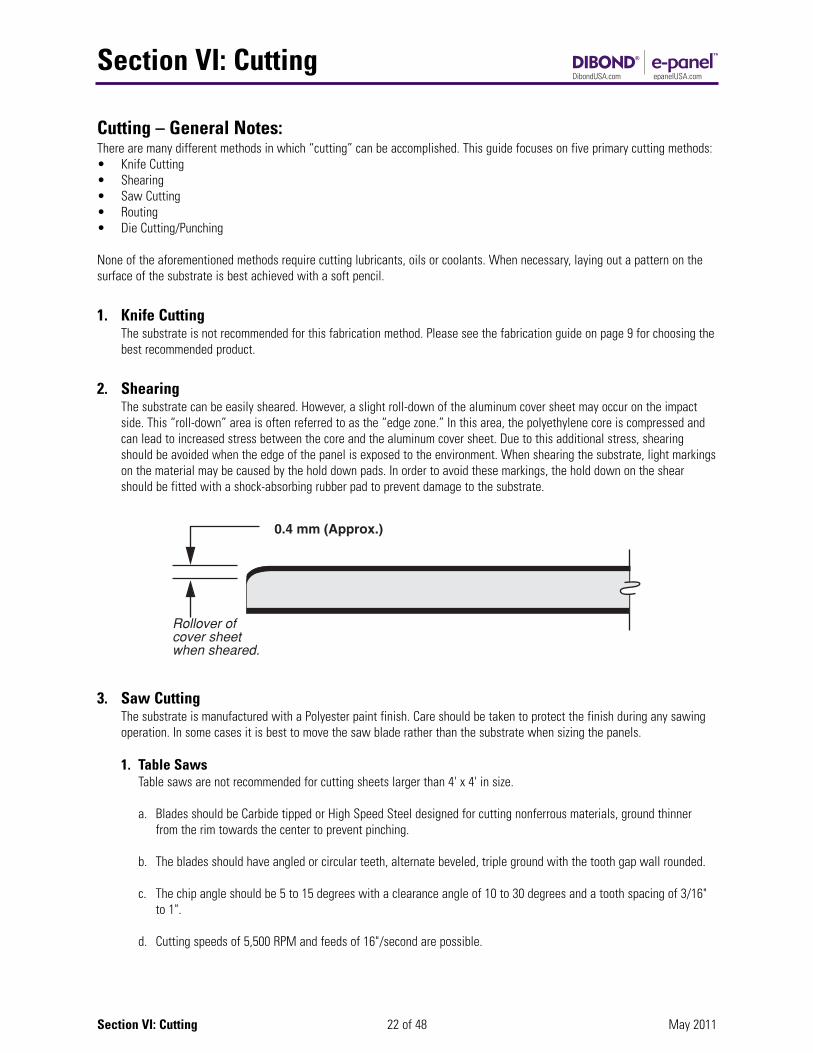
2. ShearingThe substrate can be easily sheared. However, a slight roll-down of the aluminum cover sheet may occur on the impact side. This “roll-down” area is often referred to as the “edge zone.” In this area, the polyethylene core is compressed and can lead to increased stress between the core and the aluminum cover sheet. Due to this additional stress, shearing should be avoided when the edge of the panel is exposed to the environment. When shearing the substrate, light markingson the material may be caused by the hold down pads. In order to avoid these markings, the hold down on the shear should be fitted with a shock-absorbing rubber pad to prevent damage to the substrate.
3. Saw CuttingThe substrate is manufactured with a Polyester paint finish. Care should be taken to protect the finish during any sawingoperation. In some cases it is best to move the saw blade rather than the substrate when sizing the panels.
1. Table SawsTable saws are not recommended for cutting sheets larger than 4' x 4' in size.
a. Blades should be Carbide tipped or High Speed Steel designed for cutting nonferrous materials, ground thinner from the rim towards the center to prevent pinching.
b. The blades should have angled or circular teeth, alternate beveled, triple ground with the tooth gap wall rounded.
c. The chip angle should be 5 to 15 degrees with a clearance angle of 10 to 30 degrees and a tooth spacing of 3/16" to 1".
d. Cutting speeds of 5,500 RPM and feeds of 16"/second are possible.
Section VI: Cutting
23 of 48 May 2011Section VI: Cutting
2. Panel Sawsa. Panel saws provide an effective method of cutting the substrate. These saws, whether standard equipment or
custom made, perform well and have the added advantage of space savings.
b. Blades should be the same type used for table saws.
3. Multiple Operation Rip/V-grooving Sawsa. These saws are typically used for high volume production operations.
b. Blades should be the same type used for Table Saws.
4. Portable (Circular) Sawsa. Circular saws are also used effectively to cut the substrate. These saws should be production/industrial type
equipment.
b. Blades should be the same type used for table saws.
5. Reciprocating Sawsa. Reciprocating saws work well for cutouts. Care should be taken with portable and reciprocating saws to prevent
damage to the substrate surface.
b. More than one sheet can be cut at a time by stacking panels.
c. If center cutting (i.e. Letter cutouts) is required, a foam pad may be placed under the substrate with the reciprocating blade cutting into the foam.
d. The sheets may be clamped or secured with double-faced tape for the cutting operation. When clamping between jaws, protect the panel surface against damage.
e. Blades should be high speed steel, .03" to .047" thick, 3/16" to 9/16" wide, with hook or circular teeth with alternateangles, set or waved at a spacing of .010" to .250".
f. Cutting feeds up to 4"/second are possible.
6. Band Sawsa. Band saws may be used to cut irregular shapes or curves.
b. Blades should be tempered spring strip steel, .03" to .047" thick, 9/16" to 1" wide, with skip teeth designed for nonferrous and ferrous materials spaced at a minimum of 10 teeth per inch.
c. Cutting speeds of 10,000 FPM at a cutting feed of 10"/second are possible.
Section VI: Cutting
24 of 48 May 2011Section VI: Cutting
4. Routing – General Notes:The substrate can be cut to size using either portable commercial or automated routing equipment. Bits should be carbide tipped and kept sharp. Single or multiple flutes may be used.
1. Routing: For Bendinga. e-panel is not recommended for this fabrication method as it is for flat sheet applications only.
Please see the fabrication guide on page 9 for choosing the best recommended product.
b. The substrate can be accurately folded by hand after a simple routing operation is done on the back skin. Thisfabrication method is called Rout and Return. It is unique to metal composite panel fabrication. Do not use a press brake for tight folds of the substrate. The material may be routed by using one of the two following methods:
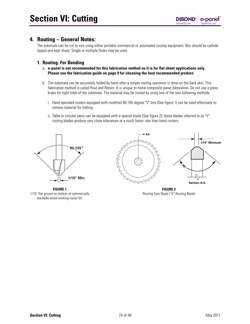
i. Hand operated routers equipped with modified 90-105 degree "V" bits (See figure 1) can be used effectively to remove material for folding.
ii. Table or circular saws can be equipped with a special blade (See figure 2); these blades referred to as "V"routing blades produce very close tolerances at a much faster rate than hand routers.
FIGURE 11/16" flat ground on bottom of commercially
available wood working router bit.
AA
FIGURE 2Routing Saw Blade (“V” Routing Blade)
1/16" Minimum
Section A-A
90˚
Section VI: Cutting
25 of 48 May 2011Section VI: Cutting
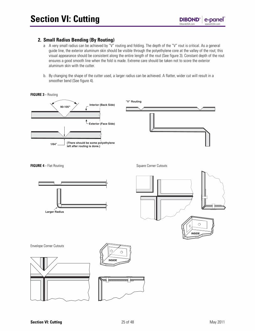
2. Small Radius Bending (By Routing)a A very small radius can be achieved by “V” routing and folding. The depth of the “V” rout is critical. As a general
guide line, the exterior aluminum skin should be visible through the polyethylene core at the valley of the rout; this visual appearance should be consistent along the entire length of the rout (See figure 3). Constant depth of the routensures a good smooth line when the fold is made. Extreme care should be taken not to score the exterior aluminum skin with the cutter.
b. By changing the shape of the cutter used, a larger radius can be achieved. A flatter, wider cut will result in a smoother bend (See figure 4).
FIGURE 4 - Flat Routing
FIGURE 3 - Routing
INSIDE
INSIDE
Envelope Corner Cutouts
Square Corner Cutouts

Section VI: Cutting
26 of 48 May 2011Section VI: Cutting
3. Making Cornersa. An aluminum composite panel requires a “grooving” operation along any fold line prior to bending. This operation
can be done with a custom saw blade or a customized router bit. Regardless of the tooling used the groove iscommonly called a “rout.” The most common rout is a modified “90° V” with a flattened (1/8" wide minimum)bottom. The reason for this modification is so that the aluminum skin does not overstress during the bending process. Once correctly done, this V-Rout allows the composite panel to be folded along the rout from 0° to 90° easily. The term “Rout and Return” means that a panel has been routed and the edge returned or folded.
b. A rout made with profiles other than 90° allows the substrate to be bent to various angles. These profiles eliminatefabrication problems and combine to create different joining techniques. Two additional common router profilesdiscussed in this document are the 135° and the Flat Rout.
4. Common 90° V-Routed Cornera. The most common corner is a 90° Rout and Return. This corner is made by folding a V-Routed panel to a 90° angle.
b. It is critical that the modified V-Rout is made to the correct depth to create a good return angle. “Spring back” will occur if the rout is not deep enough, however, extreme care should be taken not to score the exterior aluminum skinwith the router bit or blade during the routing operation so that the aluminum skin is not weakened. The depth iscorrect when the exterior skin is intact with approximately 1/64" of polyethylene in the bottom of the V-Rout and the return does not “spring back” when folded.
Folded V-Routed CornerModified V-Rout in Dibond®
90° V-Router Bits & Blades
Section VI: Cutting
27 of 48 May 2011Section VI: Cutting
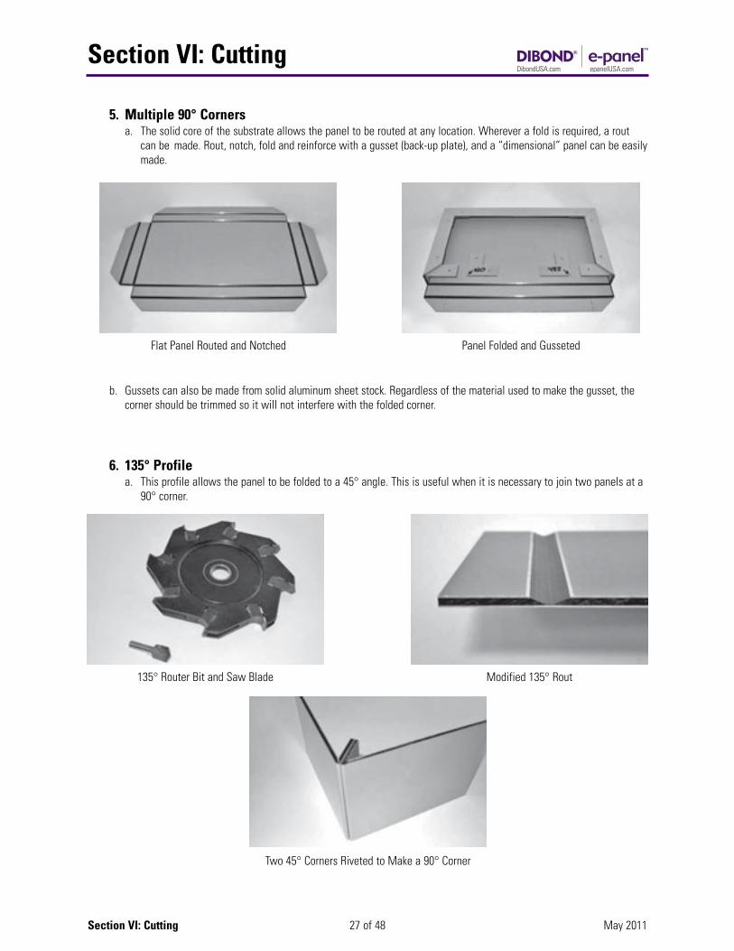
5. Multiple 90° Cornersa. The solid core of the substrate allows the panel to be routed at any location. Wherever a fold is required, a rout
can be made. Rout, notch, fold and reinforce with a gusset (back-up plate), and a “dimensional” panel can be easilymade.
b. Gussets can also be made from solid aluminum sheet stock. Regardless of the material used to make the gusset, the corner should be trimmed so it will not interfere with the folded corner.
Flat Panel Routed and Notched Panel Folded and Gusseted
6. 135° Profilea. This profile allows the panel to be folded to a 45° angle. This is useful when it is necessary to join two panels at a
90° corner.
135° Router Bit and Saw Blade Modified 135° Rout
Two 45° Corners Riveted to Make a 90° Corner
Section VI: Cutting
28 of 48 May 2011Section VI: Cutting
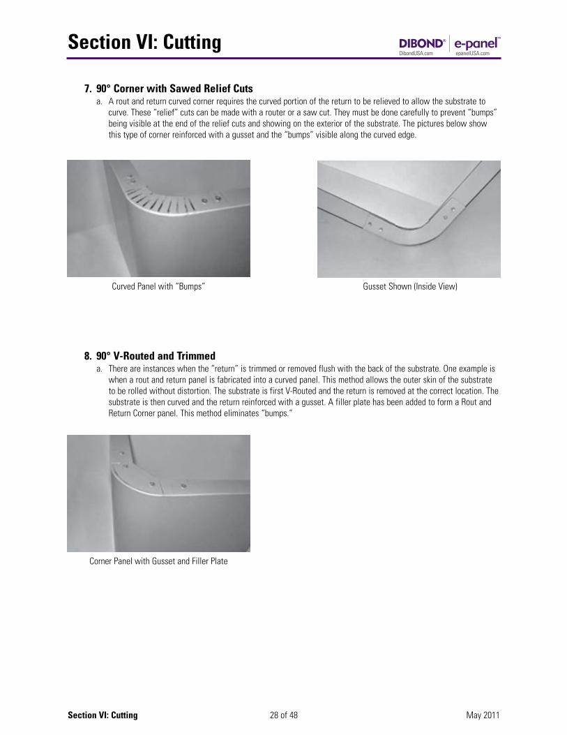
7. 90° Corner with Sawed Relief Cutsa. A rout and return curved corner requires the curved portion of the return to be relieved to allow the substrate to
curve. These “relief” cuts can be made with a router or a saw cut. They must be done carefully to prevent “bumps” being visible at the end of the relief cuts and showing on the exterior of the substrate. The pictures below show this type of corner reinforced with a gusset and the “bumps” visible along the curved edge.
Curved Panel with “Bumps” Gusset Shown (Inside View)
8. 90° V-Routed and Trimmeda. There are instances when the “return” is trimmed or removed flush with the back of the substrate. One example is
when a rout and return panel is fabricated into a curved panel. This method allows the outer skin of the substrate to be rolled without distortion. The substrate is first V-Routed and the return is removed at the correct location. Thesubstrate is then curved and the return reinforced with a gusset. A filler plate has been added to form a Rout and Return Corner panel. This method eliminates “bumps.”
Corner Panel with Gusset and Filler Plate
Section VI: Cutting
29 of 48 May 2011Section VI: Cutting
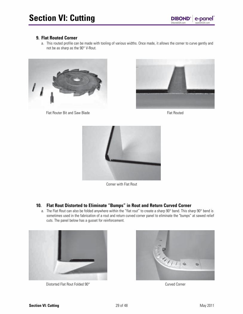
9. Flat Routed Cornera. This routed profile can be made with tooling of various widths. Once made, it allows the corner to curve gently and
not be as sharp as the 90° V-Rout.
Flat Router Bit and Saw Blade Flat Routed
Distorted Flat Rout Folded 90° Curved Corner
Corner with Flat Rout
10. Flat Rout Distorted to Eliminate “Bumps” in Rout and Return Curved Cornera. The Flat Rout can also be folded anywhere within the “flat rout” to create a sharp 90° bend. This sharp 90° bend is
sometimes used in the fabrication of a rout and return curved corner panel to eliminate the "bumps” at sawed reliefcuts. The panel below has a gusset for reinforcement.

Section VI: Cutting
30 of 48 May 2011Section VI: Cutting
11. Flat Rout Used to Make a “Hem and Cope”a. The only time a rout is set to a depth to remove the entire core material is when a “Hem” or “Cope” is needed.
Both are made using a flat rout. A cope makes a support (sometimes called a rabbet joint) at the edge of thesubstrate. It is generally routed to the same width as the substrate thickness. A hem is made by first cutting a copeand then bending the remaining skin over the core material. These two flat routed conditions can be usedindependently or together to solve many fabrication needs.
Cope at Edge of Panel Folded Cope (A Hem)
Cope at Edge of Panel Folded Cope (A Hem)
Section VII: Embossing
Section VI: Cutting
31 of 48 May 2011Section VII: Embossing
5. Die Cutting/PunchingDie cutting and/or Punching is a method for the rapid production of flat shapes or cutouts. Typical applications would include the die cutting of:
• Letters and shapes.• Openings in a sheet used as part of an assembly• Puzzle pieces
Die cutting and punching processes are similar in that they both can provide a curved shape by cutting through a substrate.Die cutting, however, uses one steel rule die that comes in contact with a flat platen, whereas, a punch has two designed shapes, a male and a female that cut the shape when pressed together.
Die cutting is typically used with lighter weight paper or foam type materials, where punches are used for heavier materials.
Prior to die cutting, the substrate can be painted or screen printed.
1. A Note on PunchingThe punching of holes or flat-formed parts using the substrate is performed in the same way as for solid aluminum sheet. Evenly ground tools and the narrowest possible cutting gap will provide the best results. The substrate can be punched with a male-female die.
2. Steel Rule Die Cutting ProcessThe substrate is not recommended for this fabrication method. Please see the fabrication guide on page 9 for choosing the best recommended product.
EmbossingThe substrate is not recommended for this fabrication method. Please see the fabrication guide on page 9 for choosing the bestrecommended product.
Section VI: Cutting

Section VIII: Forming Curves
32 of 48 May 2011
Forming Curves – General Notese-panel is not suitable for this fabrication method as it is for flat sheet applications only. Please see thefabrication guide on page 9 for choosing the best recommended product. The forming of curves can be accomplishedwith the substrate to provide a unique dimensional effect. Curves are typically formed by cold forming.
Curving Through Cold FormingFor forming curves requiring cutting techniques, see Section on Cutting.
The minimum curving radius of the substrate without routing the back skin is 30 times the thickness of the material. For example,using a 2mm thick sheet: 2mm x 30 = 60mm radius (2-3/8").
The substrate may be curved using one of the three methods common to the sheet metal industry:
Section VIII: Forming Curves
TABLECLAMP
HINGE
PIPE
R = RadiusT = Thickness
Bending Over aClamped Pipe
1. Pyramid RollerThe use of a pyramid roller to curve the substrate is an acceptable method of obtaining a radius.
As a precaution, film should be used between the substrate and the rollers to protect the substrate surface.
2. Press BrakeWhen forming with a brake press, use a top die with the desired radius.
The lower die should always have a protective film of less than 1/8".
The radius of the top die will be the approximate inside radius of the finished panel.
The end of the substrate should extend at least 10 timesits thickness from the tangential contact point of thebending die.
3. Bending Over a Clamped PipeThe substrate may be bent over a pipe of desired radius that is securely clamped to a table.
A hinged “leaf” attached to the end of the table will bendthe substrate easily.
Press Brake
2" to 4" Tail
Pyramid Roller
Appendix I: MSDS
33 of 48 May 2011Appendix I: MSDS
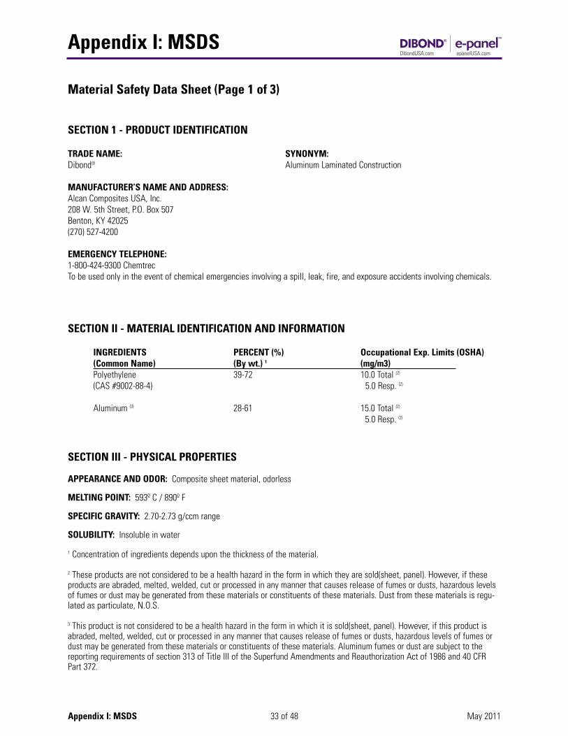
Material Safety Data Sheet (Page 1 of 3)
SECTION 1 - PRODUCT IDENTIFICATION
TRADE NAME: SYNONYM: Dibond® Aluminum Laminated Construction
MANUFACTURER’S NAME AND ADDRESS:Alcan Composites USA, Inc.208 W. 5th Street, P.O. Box 507Benton, KY 42025(270) 527-4200
EMERGENCY TELEPHONE:1-800-424-9300 ChemtrecTo be used only in the event of chemical emergencies involving a spill, leak, fire, and exposure accidents involving chemicals.
SECTION II - MATERIAL IDENTIFICATION AND INFORMATION
INGREDIENTS PERCENT (%) Occupational Exp. Limits (OSHA)(Common Name) (By wt.) 1 (mg/m3)Polyethylene 39-72 10.0 Total (2)
(CAS #9002-88-4) 5.0 Resp. (2)
Aluminum (3) 28-61 15.0 Total (2)
5.0 Resp. (2)
SECTION III - PHYSICAL PROPERTIES
APPEARANCE AND ODOR: Composite sheet material, odorless
MELTING POINT: 593º C / 890º F
SPECIFIC GRAVITY: 2.70-2.73 g/ccm range
SOLUBILITY: Insoluble in water
1 Concentration of ingredients depends upon the thickness of the material.
2 These products are not considered to be a health hazard in the form in which they are sold(sheet, panel). However, if theseproducts are abraded, melted, welded, cut or processed in any manner that causes release of fumes or dusts, hazardous levelsof fumes or dust may be generated from these materials or constituents of these materials. Dust from these materials is regu-lated as particulate, N.O.S.
3 This product is not considered to be a health hazard in the form in which it is sold(sheet, panel). However, if this product isabraded, melted, welded, cut or processed in any manner that causes release of fumes or dusts, hazardous levels of fumes ordust may be generated from these materials or constituents of these materials. Aluminum fumes or dust are subject to thereporting requirements of section 313 of Title III of the Superfund Amendments and Reauthorization Act of 1986 and 40 CFRPart 372.
Appendix I: MSDS
34 of 48Appendix I: MSDS May 2011
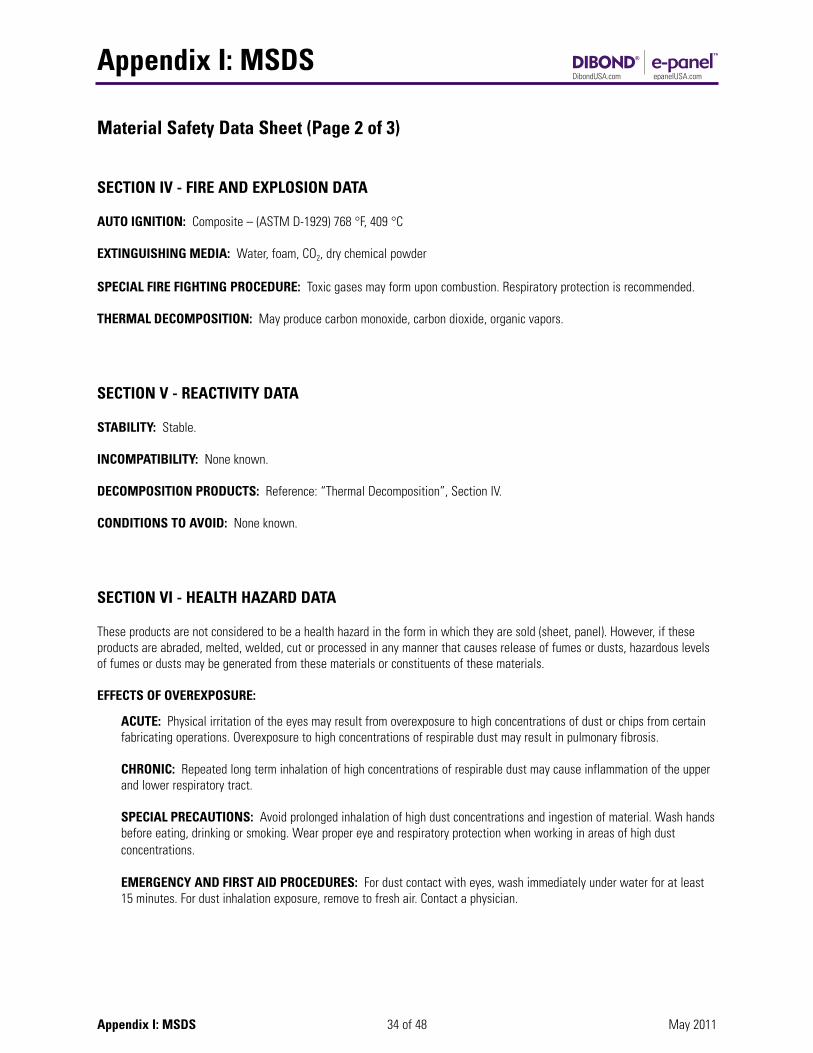
Material Safety Data Sheet (Page 2 of 3)
SECTION IV - FIRE AND EXPLOSION DATA
AUTO IGNITION: Composite – (ASTM D-1929) 768 °F, 409 °C
EXTINGUISHING MEDIA: Water, foam, CO2, dry chemical powder
SPECIAL FIRE FIGHTING PROCEDURE: Toxic gases may form upon combustion. Respiratory protection is recommended.
THERMAL DECOMPOSITION: May produce carbon monoxide, carbon dioxide, organic vapors.
SECTION V - REACTIVITY DATA
STABILITY: Stable.
INCOMPATIBILITY: None known.
DECOMPOSITION PRODUCTS: Reference: “Thermal Decomposition”, Section IV.
CONDITIONS TO AVOID: None known.
SECTION VI - HEALTH HAZARD DATA
These products are not considered to be a health hazard in the form in which they are sold (sheet, panel). However, if theseproducts are abraded, melted, welded, cut or processed in any manner that causes release of fumes or dusts, hazardous levelsof fumes or dusts may be generated from these materials or constituents of these materials.
EFFECTS OF OVEREXPOSURE:
ACUTE: Physical irritation of the eyes may result from overexposure to high concentrations of dust or chips from certain fabricating operations. Overexposure to high concentrations of respirable dust may result in pulmonary fibrosis.
CHRONIC: Repeated long term inhalation of high concentrations of respirable dust may cause inflammation of the upper and lower respiratory tract.
SPECIAL PRECAUTIONS: Avoid prolonged inhalation of high dust concentrations and ingestion of material. Wash handsbefore eating, drinking or smoking. Wear proper eye and respiratory protection when working in areas of high dust concentrations.
EMERGENCY AND FIRST AID PROCEDURES: For dust contact with eyes, wash immediately under water for at least 15 minutes. For dust inhalation exposure, remove to fresh air. Contact a physician.
Appendix I: MSDS
35 of 48Appendix I: MSDS May 2011
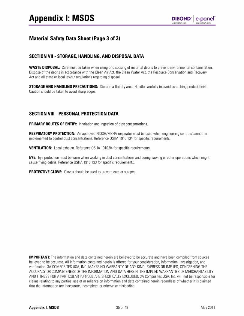
Material Safety Data Sheet (Page 3 of 3)
SECTION VII - STORAGE, HANDLING, AND DISPOSAL DATA
WASTE DISPOSAL: Care must be taken when using or disposing of material debris to prevent environmental contamination.Dispose of the debris in accordance with the Clean Air Act, the Clean Water Act, the Resource Conservation and RecoveryAct and all state or local laws / regulations regarding disposal.
STORAGE AND HANDLING PRECAUTIONS: Store in a flat dry area. Handle carefully to avoid scratching product finish.Caution should be taken to avoid sharp edges.
SECTION VIII - PERSONAL PROTECTION DATA
PRIMARY ROUTES OF ENTRY: Inhalation and ingestion of dust concentrations.
RESPIRATORY PROTECTION: An approved NIOSH/MSHA respirator must be used when engineering controls cannot beimplemented to control dust concentrations. Reference OSHA 1910.134 for specific requirements.
VENTILATION: Local exhaust. Reference OSHA 1910.94 for specific requirements.
EYE: Eye protection must be worn when working in dust concentrations and during sawing or other operations which mightcause flying debris. Reference OSHA 1910.133 for specific requirements.
PROTECTIVE GLOVE: Gloves should be used to prevent cuts or scrapes.
IMPORTANT: The information and data contained herein are believed to be accurate and have been compiled from sourcesbelieved to be accurate. All information contained herein is offered for your consideration, information, investigation, andverification. 3A COMPOSITES USA, INC. MAKES NO WARRANTY OF ANY KIND, EXPRESS OR IMPLIED, CONCERNING THEACCURACY OR COMPLETENESS OF THE INFORMATION AND DATA HEREIN. THE IMPLIED WARRANTIES OF MERCHANTABILITYAND FITNESS FOR A PARTICULAR PURPOSE ARE SPECIFICALLY EXCLUDED. 3A Composites USA, Inc. will not be responsible forclaims relating to any parties’ use of or reliance on information and data contained herein regardless of whether it is claimedthat the information are inaccurate, incomplete, or otherwise misleading.

Appendix II: Specifications
36 of 48 May 2011Appendix II: Specifications
Adhesives
Adhesives Used with Dibond® Material One of the display features in great demand is the ability to attach Dibond® Material to a substrate without having exposed fasteners. Although there are some techniques to accomplish this using conventional fasteners, the vast majority of this typeconnection is done using adhesives. To develop some general guidelines, 3A Composites USA Inc. has reviewed some well-known adhesives and can present the following information.
The following General Guidelines have been established based on the research done into the use of adhesives on Dibond®
material.
1. To achieve reliable bonding, it is imperative to follow the adhesive manufacturer’s application instructions.
2. Although many adhesive materials work well on the coil coated paint finishes on Dibond® Material, no product, either adhesive or tape, has been found that will adhere to the polyethylene core material. All attachments should be made through contact with the painted aluminum facers of Dibond® material.
3. Care must be taken in the selection of an adhesive regarding the thermal expansion of the materials to be joined. Where significant thermal expansion can occur (i.e. exterior applications) adhesives should be of medium or low modulus materials to allow for movement without shear or loss of bond. For interior applications where thermal expansion is not a consideration, high modulus adhesives can be used to join materials.
4. Cure time is generally a consideration in the choice of adhesives. Silicones take a good deal of time to cure before a load can be applied whereas the faster curing adhesives do not have the movement capabilities to meet the project needs. In these instances, a combination of double sided foam tape and adhesive is often used.
Example: Two pieces of Dibond® Material must be connected for a strong permanent bond in a short period of time. The adhesive area is 2" by 36".
Many times a strip of double sided foam tape (approx. 3/4" wide) will be applied next to a bead of silicone adhesive. For thenear term, the tape holds the Dibond®. For the longer term, the silicone adhesive will cure and relieve the load applied to the tape.
Adhesive Research Results The following adhesives have been shown to adhere to Dibond® Material. For specific questions about the adhesive, pleaserefer to the adhesive manufacturer guidelines.
Isopropyl alcohol two-cloth cleaning method is a minimal surface preparation for all adhesive bonding.
1-Part Silicones, Adhesives and Sealants: • Dow 995: 1-part silicone structural adhesive
• Pecora 864, 890, 895: 1-part silicone sealant
• Tremco Spectrem 1, Spectrem 2, Proglaze SG: 1-part silicone sealant
• Schnee Morehead SM5731, 1-part silicone sealant
• GE SCS2800, SCS9000, SCS2000, SCS2900, GE7000, 1-part silicone sealant
Isopropyl alcohol two-cloth cleaning method is a minimal surface preparation for all adhesive bonding.
Appendix II: Specifications
37 of 48 May 2011Appendix II: Specifications
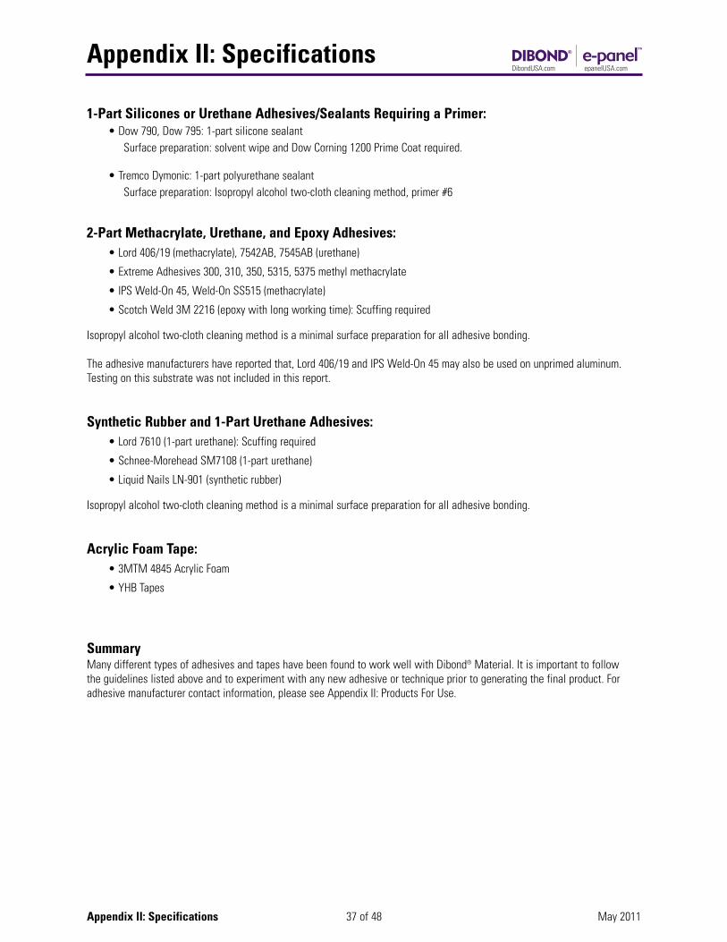
1-Part Silicones or Urethane Adhesives/Sealants Requiring a Primer: • Dow 790, Dow 795: 1-part silicone sealant
Surface preparation: solvent wipe and Dow Corning 1200 Prime Coat required.
• Tremco Dymonic: 1-part polyurethane sealant Surface preparation: Isopropyl alcohol two-cloth cleaning method, primer #6
2-Part Methacrylate, Urethane, and Epoxy Adhesives: • Lord 406/19 (methacrylate), 7542AB, 7545AB (urethane)
• Extreme Adhesives 300, 310, 350, 5315, 5375 methyl methacrylate
• IPS Weld-On 45, Weld-On SS515 (methacrylate)
• Scotch Weld 3M 2216 (epoxy with long working time): Scuffing required
Isopropyl alcohol two-cloth cleaning method is a minimal surface preparation for all adhesive bonding.
The adhesive manufacturers have reported that, Lord 406/19 and IPS Weld-On 45 may also be used on unprimed aluminum.Testing on this substrate was not included in this report.
Synthetic Rubber and 1-Part Urethane Adhesives: • Lord 7610 (1-part urethane): Scuffing required
• Schnee-Morehead SM7108 (1-part urethane)
• Liquid Nails LN-901 (synthetic rubber)
Isopropyl alcohol two-cloth cleaning method is a minimal surface preparation for all adhesive bonding.
Acrylic Foam Tape: • 3MTM 4845 Acrylic Foam
• YHB Tapes
Summary Many different types of adhesives and tapes have been found to work well with Dibond® Material. It is important to follow the guidelines listed above and to experiment with any new adhesive or technique prior to generating the final product. Foradhesive manufacturer contact information, please see Appendix II: Products For Use.
Appendix II: Specifications
38 of 48 May 2011Appendix II: Specifications
Fastening
Joining Dibond MaterialTypical methods of joining Dibond material are the use of threaded fasteners, rivets, adhesives and double-faced high strengthtapes.
Proper consideration should be given to the thermal expansion characteristics of Dibond material. See Thermal Expansion Section.
Use the general guidelines listed below when other elements come in direct contact with the surface of Dibond material. It isalways recommended to trial application various joining techniques to ensure success.
1. Acceptable Joining Element Materials:• Aluminum• Plastic• Stainless Steel
2. Unacceptable Joining Elements:• Copper• Brass• Bronze• Iron• Raw Steel
Unacceptable materials may cause corrosion of joining surface due to electrolysis of dissimilar materials.
Threaded FastenersThreaded fasteners will allow the removal of the panel if needed. The use of a large flat washer will aid to minimize surfacepressure and possible compression due to cold flow of the core material. Placement of the threaded fasteners should not beless than .75" from the edge of the sheet. It is not recommended to torque fasteners due to the cold flow of the core material,one turn past finger tight is common practice.
RivetsPanels of Dibond material can be fastened together or joined to aluminum extrusion profiles with rivets common to aluminumconstruction. Rivet connections are well suited for parts that may be subjected to vibration. Colored plastic concealment capscan be used to conceal the exposed rivet head. Consult the rivet manufacturer for details.
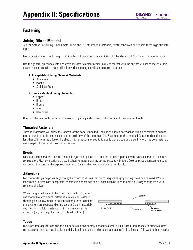
AdhesivesFor interior design purposes, high strength contact adhesives that do not require lengthy setting times can be used. Wheremoderate cure times are acceptable, construction adhesives and silicones can be used to obtain a stronger bond than with contact adhesives.
When using an adhesive to hold dissimilar materials, selectone that will allow thermal differential movement withoutshearing. Use a low modulus sealant where greater amountsof movement are expected (i.e., plastics to Dibond material),and medium modulus sealants if minimum movement isexpected (i.e., bonding aluminum to Dibond material).
TapesFor stress-free applications and to hold parts while the primary adhesives cures, double-faced foam tapes are effective. Bothsurfaces to be bonded must be clean and dry. It is important that the tape manufacturer’s directions are followed for best results.
CUTOUT
PLASTIC SILICONE1/8" MINIMUM
FOAM TAPE
Appendix II: Specifications
39 of 48 May 2011Appendix II: Specifications
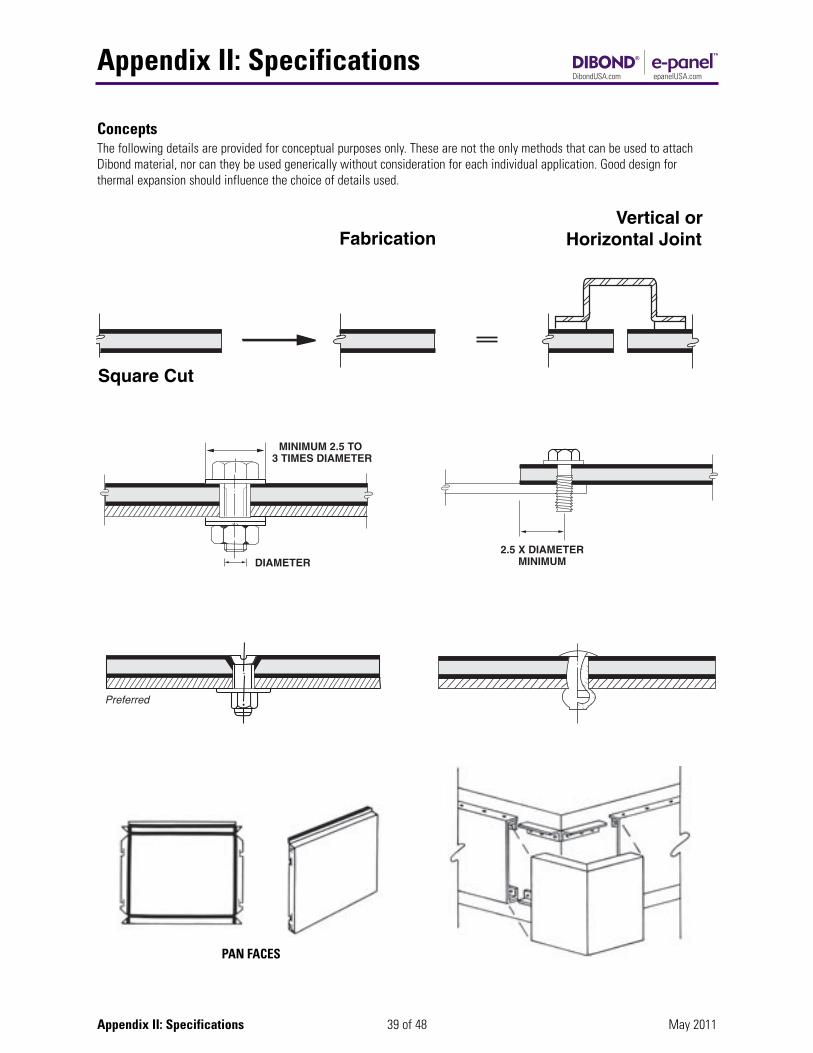
ConceptsThe following details are provided for conceptual purposes only. These are not the only methods that can be used to attachDibond material, nor can they be used generically without consideration for each individual application. Good design for thermal expansion should influence the choice of details used.
Square Cut
Fabrication Vertical orHorizontal Joint
PAN FACES
Appendix II: Specifications
40 of 48 May 2011Appendix II: Specifications
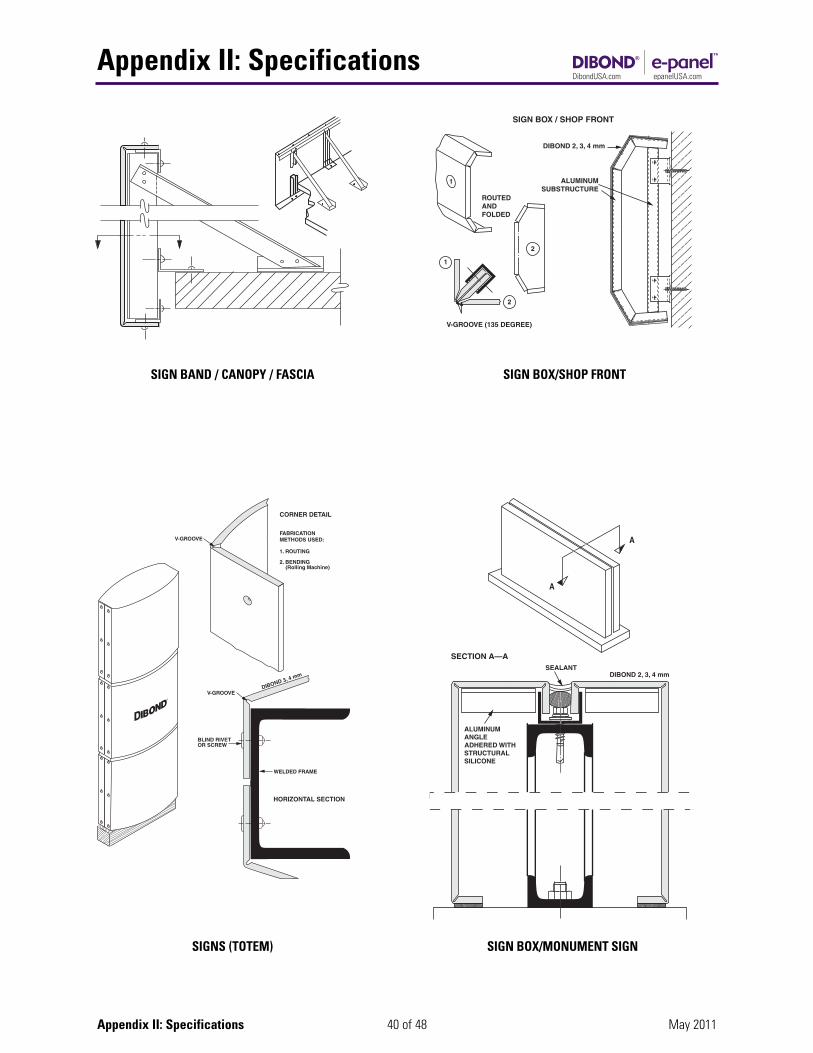
SIGNS (TOTEM) SIGN BOX/MONUMENT SIGN
SIGN BOX/SHOP FRONTSIGN BAND / CANOPY / FASCIA
Appendix II: Specifications
41 of 48 May 2011Appendix II: Specifications
DrillingDibond material can be drilled with twist drills usually used for aluminum and plastics, and on drilling machines customarilyused for metals.
WORKING SPECIFICATIONS:Drill bit: Twist drill, high speed steel Tip Angle: 100-140 degrees, or counter-bore grind with centering tip Cutting speed: 164 RPM to 984 RPM
Quick removal of chips can be achieved by a high RPM, slow feed speed and occasional lifting of the bit.
Thermal ExpansionThermal expansion should always be considered in designs using Dibond material. Dibond material has been tested and has a rate of expansion of .000156"/FT/°F. That translates into approximately an 1/8" movement in an 8' panel with a 100°F temperature change. Temperature differences must be considered between shop (fabrication) temperature and the highest andlowest panel temperature. Care should always be taken to avoid restricting thermal movement of the panel to eliminate unacceptable bowing or over stressing of the fasteners.
The coefficient of expansion for unlike materials should be considered in joint design.
Storage GuidelinesDibond is to be stored inside in a dry and clean area. Material must be stored flat.
Dibond material should always be stored in a cool dry area where temperatures are relatively stable. Excessive temperaturefluctuations may cause condensation to form on the stored sheets possibly resulting in permanent damage. Do not allow moisture to reach stored material.
The best way to store Dibond material is to lay it flat. If a rack storage system is decided upon, use the base of the crate as abottom support for the material to rest on. If Dibond material is leaned on its side, it should be positioned to learn on the horizontal edge of the material only. Dibond material panels should be handled carefully when removing the panels from storage so that they do not slide against each other or so they don’t slide over a rough surface to avoid panel damage. Verticalstacking of Dibond material is not recommended.
Appendix II: Specifications
42 of 48 May 2011
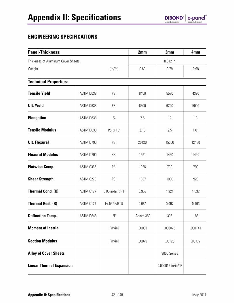
ENGINEERING SPECIFICATIONS
Panel-Thickness: 2mm 3mm 4mm
Thickness of Aluminum Cover Sheets 0.012 in
Weight [lb/ft2] 0.60 0.79 0.98
Technical Properties:
Tensile Yield ASTM D638 PSI 8450 5580 4390
Ult. Yield ASTM D638 PSI 8500 6220 5000
Elongation ASTM D638 % 7.6 12 13
Tensile Modulus ASTM D638 PSI x 106 2.13 2.5 1.81
Ult. Flexural ASTM D790 PSI 20120 15050 12180
Flexural Modulus ASTM D790 KSI 1391 1430 1440
Flatwise Comp. ASTM C365 PSI 1026 739 790
Shear Strength ASTM C273 PSI 1637 1030 920
Thermal Cond. (K) ASTM C177 BTU-in/hr.ft2-°F 0.953 1.221 1.532
Thermal Rest. (R) ASTM C177 Hr.ft2-°F/BTU 0.084 0.097 0.103
Deflection Temp. ASTM D648 °F Above 350 303 188
Moment of Inertia [in4/in] .00003 .000075 .000141
Section Modulus [in3/in] .00079 .00126 .00172
Alloy of Cover Sheets 3000 Series
Linear Thermal Expansion 0.000012 in/in/°F
Appendix II: Specifications
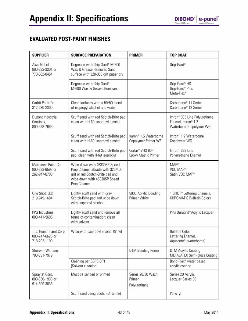
Appendix II: Specifications
43 of 48Appendix II: Specifications May 2011
EVALUATED POST-PAINT FINISHES
SUPPLIER SURFACE PREPARATION PRIMER TOP COAT
Akzo Nobel Degrease with Grip-Gard® M-600 Grip-Gard®
800-233-3301 or Wax & Grease Remover. Sand770-662-8464 surface with 320-360 grit paper dry
Degrease with Grip-Gard® Grip-Gard® HSM-600 Wax & Grease Remover. Grip-Gard® Plus
Meta-Flex®
Carbit Paint Co. Clean surfaces with a 50/50 blend Carbithane® 11 Series 312-280-2300 of isopropyl alcohol and water Carbithane® 12 Series
Dupont Industrial Scuff sand with red Scotch-Brite pad, Imron® 333 Line PolyurethaneCoatings, clean with H-69 isopropyl alcohol Enamel, Imron® 1.2800-338-7668 Waterborne Copolymer WG
Scuff sand with red Scotch-Brite pad, Imron® 1.5 Waterborne Imron® 1.2 Waterborneclean with H-69 isopropyl alcohol Copolymer Primer WF Copolymer WG
Scuff sand with red Scotch-Brite pad, Corlar® VHS 90P Imron® 333 Linepad, clean with H-69 isopropyl Epoxy Mastic Primer Polyurethane Enamel
Matthews Paint Co. Wipe down with 45330SP Speed MAP®
800-323-6593 or Prep Cleaner, abrade with 320/400 VOC MAP®
262-947-0700 grit or red Scotch-Brite pad and Satin VOC MAP®
wipe down with 45330SP SpeedPrep Cleaner
One Shot, LLC Lightly scuff sand with gray 5005 Acrylic Bonding 1 SHOT® Lettering Enamels,219-949-1684 Scotch-Brite pad and wipe down Primer White CHROMATIC Bulletin Colors
with isopropyl alcohol
PPG Industries Lightly scuff sand and remove all PPG Duracryl® Acrylic Lacquer800-441-9695 forms of contamination; clean
with solvent
T. J. Ronan Paint Corp. Wipe with isopropyl alcohol (91%) Bulletin Color, 800-247-6626 or Lettering Enamel,718-292-1100 Aquacote® (waterborne)
Sherwin-Williams DTM Bonding Primer DTM Acrylic Coating 700-331-7979 METALATEX Semi-gloss Coating
Cleaning per SSPC-SP1 Bond-Plex® water based(Solvent cleaning) acrylic coating
Spraylat Corp. Must be sanded or primed Series 20/30 Wash Series 20 Acrylic 800-336-1936 or Primer Lacquer Series 30914-699-3035 Polyurethane
Scuff sand using Scotch-Brite Pad Polycryl
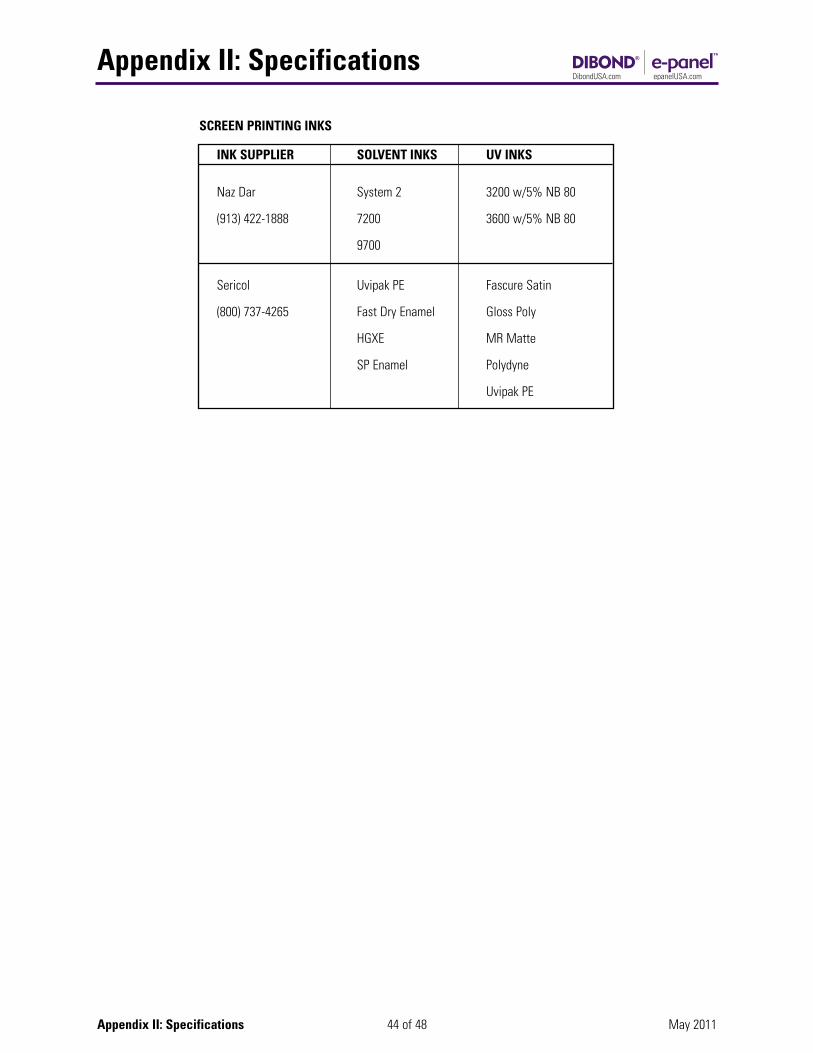
Appendix II: Specifications
44 of 48Appendix II: Specifications May 2011
INK SUPPLIER SOLVENT INKS UV INKS
Naz Dar System 2 3200 w/5% NB 80
(913) 422-1888 7200 3600 w/5% NB 80
9700
Sericol Uvipak PE Fascure Satin
(800) 737-4265 Fast Dry Enamel Gloss Poly
HGXE MR Matte
SP Enamel Polydyne
Uvipak PE
SCREEN PRINTING INKS
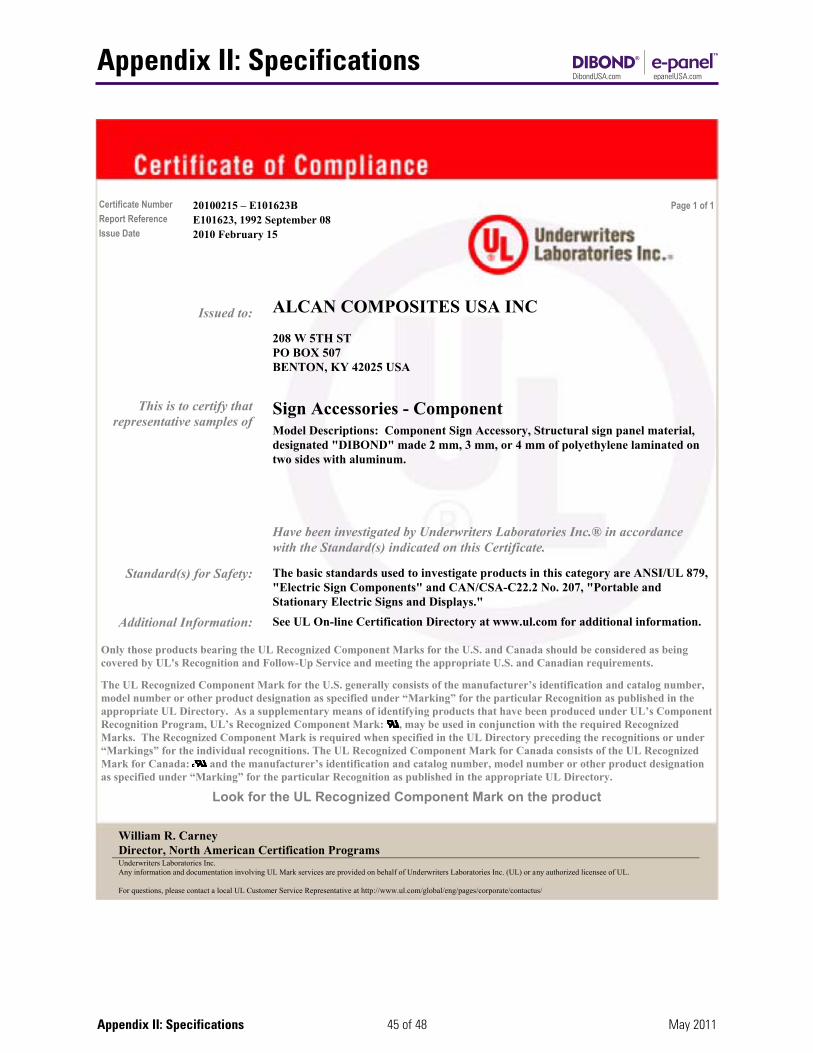
Appendix II: Specifications
45 of 48Appendix II: Specifications May 2011
Certificate Number 20100215 – E101623B Page 1 of 1 Report Reference E101623, 1992 September 08 Issue Date 2010 February 15
Issued to: ALCAN COMPOSITES USA INC
208 W 5TH ST PO BOX 507 BENTON, KY 42025 USA
Sign Accessories - Component This is to certify that representative samples of
Model Descriptions: Component Sign Accessory, Structural sign panel material, designated "DIBOND" made 2 mm, 3 mm, or 4 mm of polyethylene laminated on two sides with aluminum.
Have been investigated by Underwriters Laboratories Inc.® in accordance with the Standard(s) indicated on this Certificate.
Standard(s) for Safety: The basic standards used to investigate products in this category are ANSI/UL 879, "Electric Sign Components" and CAN/CSA-C22.2 No. 207, "Portable and Stationary Electric Signs and Displays."
Additional Information: See UL On-line Certification Directory at www.ul.com for additional information.
Only those products bearing the UL Recognized Component Marks for the U.S. and Canada should be considered as being covered by UL's Recognition and Follow-Up Service and meeting the appropriate U.S. and Canadian requirements.
The UL Recognized Component Mark for the U.S. generally consists of the manufacturer’s identification and catalog number, model number or other product designation as specified under “Marking” for the particular Recognition as published in the appropriate UL Directory. As a supplementary means of identifying products that have been produced under UL’s Component Recognition Program, UL’s Recognized Component Mark: , may be used in conjunction with the required Recognized Marks. The Recognized Component Mark is required when specified in the UL Directory preceding the recognitions or under “Markings” for the individual recognitions. The UL Recognized Component Mark for Canada consists of the UL Recognized Mark for Canada: and the manufacturer’s identification and catalog number, model number or other product designation as specified under “Marking” for the particular Recognition as published in the appropriate UL Directory.
Look for the UL Recognized Component Mark on the product
William R. Carney Director, North American Certification Programs Underwriters Laboratories Inc. Any information and documentation involving UL Mark services are provided on behalf of Underwriters Laboratories Inc. (UL) or any authorized licensee of UL. For questions, please contact a local UL Customer Service Representative at http://www.ul.com/global/eng/pages/corporate/contactus/

Appendix II: Specifications
46 of 48Appendix II: Specifications May 2011
Definitions:Target Thickness: The gauge that is to be focused on asoptimum. The Gauge Range is then used to define the limitsof the thickness that can be considered "in spec".
Gauge Range: The upper and lower limits in thickness that aproduct can be manufactured making it “in spec”.Example: Target of 250mils with a range of + or - 25 milswould be 225 mils to 275 mils.
Sheet Tolerances: We measure width, length and diagonal.Width is typically cross machine, length is typically machinedirection and diagonal is the difference in the diagonals.
Squareness: The difference in the lengths of the machinedirection sides.
Warpage / Bow: This is the measured by laying the sheetflat on a surface and measuring the amount of “smile“ or“frown“ in the center of the board in either the length orwidth. Should we have a problem described as “potato chip“this is a two direction warp, which is automatically “not inspec”.
Surface Energy (Dyne): This is measured using standarddyne solution pens
Color (ΔE): This is measured using a standard color meter.
Opacity: This is measured using a standard opacity meter.
Physical Product 2mm 3mm 4mmSpecifications
Target Thickness 2mm 3mm 4mm
Gauge ( + or - ) + / - 0.008" (0.2mm) + / - 0.008" (0.2mm) + / - 0.008" (0.2mm)
Sheet Size Tolerances
Width 0" + 0.188" (3/16") 0" + 0.188" (3/16") 0" + 0.188" (3/16")
<66"Length 66" - 96" 0" + 0.375" (3/8") 0" + 0.375" (3/8") 0" + 0.375" (3/8")
>96"
Diagonal max 1/4" max 1/4" max 1/4"
Squareness N/A N/A N/A(Cut Straightness)
Warpage / Bow Length or width Length or width Length or widthmax .8% max .8% max .8%
Surface Energy (Dyne) N/A N/A N/A
Color (ΔE) N/A N/A N/A
Opacity N/A N/A N/A
DIBOND® PRODUCT SPECIFICATIONS
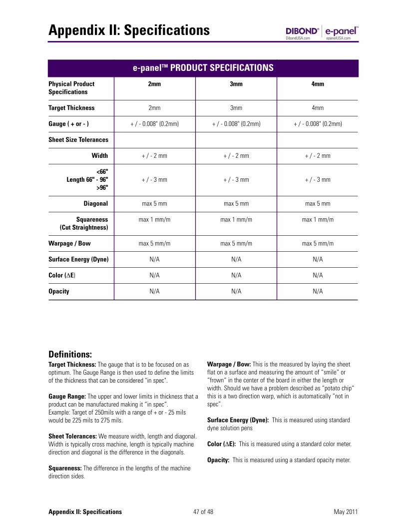
Appendix II: Specifications
47 of 48Appendix II: Specifications May 2011
Definitions:Target Thickness: The gauge that is to be focused on asoptimum. The Gauge Range is then used to define the limitsof the thickness that can be considered "in spec".
Gauge Range: The upper and lower limits in thickness that aproduct can be manufactured making it “in spec”.Example: Target of 250mils with a range of + or - 25 milswould be 225 mils to 275 mils.
Sheet Tolerances: We measure width, length and diagonal.Width is typically cross machine, length is typically machinedirection and diagonal is the difference in the diagonals.
Squareness: The difference in the lengths of the machinedirection sides.
Warpage / Bow: This is the measured by laying the sheetflat on a surface and measuring the amount of “smile“ or“frown“ in the center of the board in either the length orwidth. Should we have a problem described as “potato chip“this is a two direction warp, which is automatically “not inspec”.
Surface Energy (Dyne): This is measured using standarddyne solution pens
Color (ΔE): This is measured using a standard color meter.
Opacity: This is measured using a standard opacity meter.
Physical Product 2mm 3mm 4mmSpecifications
Target Thickness 2mm 3mm 4mm
Gauge ( + or - ) + / - 0.008" (0.2mm) + / - 0.008" (0.2mm) + / - 0.008" (0.2mm)
Sheet Size Tolerances
Width + / - 2 mm + / - 2 mm + / - 2 mm
<66"Length 66" - 96" + / - 3 mm + / - 3 mm + / - 3 mm
>96"
Diagonal max 5 mm max 5 mm max 5 mm
Squareness max 1 mm/m max 1 mm/m max 1 mm/m(Cut Straightness)
Warpage / Bow max 5 mm/m max 5 mm/m max 5 mm/m
Surface Energy (Dyne) N/A N/A N/A
Color (ΔE) N/A N/A N/A
Opacity N/A N/A N/A
e-panelTM PRODUCT SPECIFICATIONS
48 of 48 May 2011Dibond® Family Fabrication Manual
This Fabrication Manual has been developed to assist fabricators to work with the substrate in the most efficient and effective manner. The tips and suggestions contained in this manual are the result of many years of combined experience byfabricators in the U.S., Canada, South America, Asia and Europe.
These fabrication suggestions and product specifications are based on information which is, in our opinion, reliable. However,since skill, judgment, and quality of equipment and tools are involved, and since conditions and methods of using the substrate are beyond our control, the suggestions contained in this manual are provided without guarantee. We recommend thatprospective users determine the suitability of both the material and suggestions before adopting them on a commercial scale.3A COMPOSITES USA, INC., DOES NOT MAKE ANY WARRANTIES, EXPRESS OR IMPLIED, INCLUDING MERCHANTABILITYAND FITNESS FOR PURPOSE, WITH RESPECT TO ANY SAID SUGGESTIONS AND PRODUCT DATA. In no event shall 3AComposites USA, Inc., have any liability in any way related to or arising out of said suggestions and product data for direct, special, consequential or any other damages of any kind regardless of whether such liability is based on breach of contract, negligence or other tort, or breach of any warranty, express or implied.
Also, normal safety and health precautions practiced in any fabricating environment should be used when fabricating the substrate.
Dibond® is a UL recognized component.
® - registered trademark of 3A Composites USATM - trademark of 3A Composites USA© - 3A Composites USA – 2010
3A COMPOSITES USA, INC.1.800.626.3365GraphicDisplayUSA.com