Diaphragm Design Guidebook - diacom.com · DIA·COM CORPORATION The Diaphragm Company Online...
28
The Diaphragm Company Online Guidebook: www.diacom.com 603.880.1900 Diaphragm Design Guidebook
Transcript of Diaphragm Design Guidebook - diacom.com · DIA·COM CORPORATION The Diaphragm Company Online...

DIA·COM CORPORATIONThe Diaphragm Company
Online Guidebook: www.diacom.com
603.880.1900
Diaphragm Design Guidebook
2 © 2018 DiaCom Corporation
DIA·COM CORPORATIONThe Diaphragm Company 603.880.1900 · www.diacom.com
Providing Superior Solutions to Tough Sealing Problems in:
Automotive
Natural Gas
Food Processing
Industrial
Consumer Products
Water Control
Medical
Irrigation
The information contained herein is believed to be reliable, but no representations, guarantees or warranties of any kind are made as to its accuracy, suitability for particular applications or the results to be obtained therefrom. Nothing contained herein is to be considered as permission, recommendation, nor as an inducement to practice any patented invention without permission of the patent owner.
Aerospace

3© 2018 DiaCom Corporation
Why Choose DiaCom Corporation?
Since its founding in 1983, DiaCom has been committed to a single goal: the design and production of the finest molded diaphragm seals available. Today, DiaCom is an industry-leading provider of innovative, cost-effective molded diaphragm solutions that are critical to the operation of essential equipment and systems in: Industrial, Automotive, Aerospace, Medical Instrumentation, Food and Water processing, and Gas Regulator/Gas Metering Applications. Our reputation for solving the toughest sealing problems is based on our superior quality management system, our engineering expertise, and advanced manufacturing capabilities. DiaCom’s commitment to quality is reflected in our latest AS9100 Certification in
2015 and ISO 9001 certification in 2016. We are constantly striving for continuous improvement. The AS-9100 standard implements a strong focus on product quality, process control, and product conformity to specification. By encompassing our Engineering expertise and advanced manufacturing capabilities, DiaCom is able to deliver engineered diaphragm solutions that are unsurpassed in performance. DiaCom uses our core expertise of bonding industrial fabrics, fluorinated films, plastics and metals to our custom engineered elastomers in a variety of molded parts including: fabric reinforced diaphragms, molded diaphragms, rolling diaphragms, diaphragm seals, chemical septums, bellows, accumulators, valve plungers and valve seats.
Molded Diaphragms - Ideal Solutions to Tough Sealing ProblemsThe molded elastomeric diaphragm is a tough, versatile, dynamic seal that eliminates virtually all of the problems and limitations associated with other sealing methods such as U-Cups, O-Rings, metal bellows and flat, die-cut diaphragms. Unlike alternative techniques, molded diaphragms do not leak, offer no friction, have exceptional sensitivity, and display a hysteresis that is, in most cases, negligible. They can withstand pressures up to 6000 PSI over a temperature range of -65°F to 600°F, require no maintenance or lubrication, and are extremely cost-effective in most applications. DiaCom molded diaphragms are available in two forms: contoured, annular disks that provide high sensitivity and freedom of motion in short-stroke applications, and rolling diaphragms for frictionless, leak-proof sealing in cylinders and other applications requiring a long piston stroke.
These molded diaphragm features ensure unmatched performance:
• Minimum hysteresis – accurate, repeatable positioning
• No spring rate (rolling diaphragms)
• Long stroke length capabilities
• No lubrication
• No break-away or sliding friction
• Long cycle life
• Effective in harsh environments
• Constant effective pressure area
• Low assembly and associated hardware costs
DiaCom Rolling Diaphragm Theory...................................................................................................................................................4Glossary of Terms ............................................................................................................................................................................5,6Diaphragm Design Formulas .............................................................................................................................................................6General Hardware Information ....................................................................................................................................................7,8,9Rubber To Metal Bonding ..................................................................................................................................................................9PTFE/Elastomeric Diaphragm Seals ................................................................................................................................................9Diaphragm Life Design Considerations ......................................................................................................................................10,11Bead and Groove Design Considerations .....................................................................................................................................12,13Type F Diaphragms ......................................................................................................................................................................14,15Type FC Diaphragms & FC Offset Diaphragms...........................................................................................................................16,17Type D Diaphragms .....................................................................................................................................................................18,19Type DC Diaphragms .......................................................................................................................................................................20Type OA and O Diaphragms ............................................................................................................................................................21Type OB Diaphragms .......................................................................................................................................................................22Type P Diaphragms...........................................................................................................................................................................23Typical Fabric Characteristics ..........................................................................................................................................................24Chemical Compatibility Table...........................................................................................................................................................25Application Data Form......................................................................................................................................................................26The DiaCom Advantage....................................................................................................................................................................27
Table of Contents

4 © 2018 DiaCom Corporation
Figure 1 illustrates pressure reaction on the diaphragm. It can be seen that almost the entire pressure load is supported by the piston head, and only a small amount of the liquid or gas pressure is supported by the narrow convolution of the diaphragm. Also note in Figure 1 that the lines of unit pressure (acting in horizontal planes because they must be normal to the surface) force the diaphragm against the piston and cylinder sidewalls on that portion of the diaphragm in contact with the cylinder wall and piston skirt.The lines of force acting on that part of the diaphragm not in contact with the cylinder or piston skirt (the semicircular segment of the convolution) are shown in Figure 2. Each line of unit pressure (Pr) acts normal to the semicircular segment; thus any one of the pressure lines can be replaced by its horizontal and vertical component. The horizontal components, acting in opposition, cancel out each other.
The sum of the vertical components of the unit pressures acting on this semicircular segment add up to the total pressure force (F) and is equal to the normal pressure on the projection of this segment.
Considering a unit (1 inch) of circumferential length of the diaphragm, the foregoing is:
1. F = Pr x 1 x C or F = Pr x C where F = total pressure force (lbs.) Pr = normal loading or applied pressure (psi) C = convolution width (inches) The total force F is supported equally by the fabric reinforcement of the diaphragm on the piston and cylinder wall (See figure 2). Therefore tension force, Ft (lbs.), in either wall is simply one-half the value of F or 2. 2Ft = F or Ft = F 2 However, as 3. F = Pr x C then
4. Ft = Pr x C 2
Where Ft is the tension force on the diaphragm sidewall for each unit of circumferential length. Since tensile force Ft and fabric stress Sf are identical, equation 4 can be expressed in terms of fabric stress:
5. Sf = Pr x C where 2 Sf = fabric stress (lbs. per inch) Pr = normal loading or applied pressure (psi) C = convolution width (inches)
Fabric stress can be computed using equation 5. For example, if a 3-inch diameter diaphragm with an effective pressure area of 6.35 sq. in. and a convolution width of .156 is subjected to a loading pressure of 100 psi, the resulting total thrust is 635 lbs. However, fabric stress on the narrow convolution is only:
6. Sf = 100 x .156 = 7.8 lbs. per inch 2
Fabric materials are available in tensile strengths greater than 7.8 lbs. per inch. Therfore the very narrow convolution widths with resulting low stress values in the fabric fibers enable diaphragms to be used in applications involving high working pressures. In effect, DiaCom Rolling Diaphragms are pressure vessels having a variable volume
and flexible moving sidewalls. As in any other pressure vessel, its strength should be considered with respect to safety factors. Generally, diaphragms can be designed with a large safety factor. In effect, this means the maximum safe working pressure will be a fraction of the pressure that would cause failure in the convolution area. (In some aircraft applications where working pressures are as high as 1000 psi, and total cycle requirements are low, safety factors are substantially increased.) Actual stress analysis and selection of fabrics will be recommended by the DiaCom engineering department for each application.
DiaCom Rolling Diaphragm Theory
Figure 1
Figure 2
Theory:

5© 2018 DiaCom Corporation
Cylinder Diameter – The diameter across the diaphragm between the tangent points of the sidewall and cylinder radius. Measured on the fabric or low pressure side of the diaphragm.
Fabric Side – Surface of single coat diaphragm where fabric is visible. Always on low pressure side, generally on outside of diaphragm.
Height – The height of top hat and preconvoluted diaphragm is measured from the bottom of the flange to the top of the head or convolution.
Piston Diameter – The diameter across the diaphragm between the tangent points of the sidewall and piston radius. Measured on the fabric or low pressure side of the diaphragm.
Preconvoluted – A diaphragm which has its convolution molded in. No hand forming is necessary before installation.
Sidewall – That area of the diaphragm between the flange and piston areas.
Top Hat – A diaphragm molded in standard “hat” shape that must be formed into convolution before installation
Glossary of Termsll
Convolution Width – The clearance between the cylinder wall and piston skirt. By decreasing the convolution width, higher working pressures may be achieved. Generally, the convolution width should measure at least four times the diaphragm’s sidewall thickness. (See page 6 for standard convolution widths.)
Cylinder Diameter (Bore) – The inside diameter of the cylinder into which the diaphragm will fit and by which the outside diameter of the convolution will be supported.
Cylinder Radius – The blend radius between the cylinder wall and the flange.
Piston Cap – A plate which attaches to the piston, sandwiching the piston area of the diaphragm insuring the diaphragm stays in convolution.
Piston Diameter – Diameter of the piston measured across piston head, including radius.
Piston Radius – The blending radius between the piston head and the piston skirt.
Piston Skirt – The sidewall area of the piston which supports the inside diameter of the convolution
Diaphragm:
Hardware:
Top Hat Diaphragm
Preconvoluted Diaphragm

6 © 2018 DiaCom Corporation
Glossary of Terms (continued)
Bleed-through – A defect in a diaphragm caused during manufacturing where the fabric is pulled through the rubber to the high pressure side of the diaphragm. When pressure is put on the diaphragm, the rubber will be blown away from the fabric and rupture.
Blow-through – This occurs when the pressure on the diaphragm reaches a level high enough to blow a piece of the rubber through the threads of the fabric, causing a leak. This is the result of selecting a weave of fabric that is too open for the diaphragm’s thickness.
Double Coat – This is a type of diaphragm construction where the fabric is inserted between two layers of rubber.
Effective Pressure Area – The area of the diaphragm inside of an imaginary circle to the convolution midpoint on which the pressure introduced is transmitted to the opposite side of the diaphragm.
Over-stroke – Exceeding the designed stroke of the diaphragm causing it to come out of convolution. This can be avoided by designing mechanical stops into your hardware.
Reverse Pressure – When the pressure on the low pressure side of the diaphragm exceeds the pressure on the high pressure side of the diaphragm. This will cause the convolution to collapse and wrinkle. This wrinkle will cause scrubbing and lead to premature failure.
Single Coat – This is a type of diaphragm construction where there is rubber on the high pressure side and fabric on the low pressure side.
Spring Rate – This refers to the forces caused by the rubber trying to return to its as-molded position. This is generally only found in preconvoluted and dish-shaped diaphragms.
Strike-through – This refers to the amount of rubber that comes through the fabric to either fully or partially encapsulate the fabric during manufacturing.
Diaphragm Design Formulas:
(Note: Please See Page 22 for Fabric Tensile Strength)
*
Millimeters in Red
Cylinder Diameter .33 - .99 8.38 -25.15 1.0 - 2.5 24.50 - 63.50 2.51 - 4.00 63.75 - 101.60 4.01 - 8.00 203.20
Safety Factor .60 1.52 .100 2.54 .120 3.05 .140 3.56

7© 2018 DiaCom Corporation
General Hardware Informationl
Diaphragm Strokes:
Piston and Standard Convolution Width Dimensions:
Piston Cap Dimensions:
Bonnet Dimensions: Cylinder Dimensions:
Down-Stroke Position Neutral Plane Position Up-Stroke Position
Millimeters in Red
0.80
Note: A piston cap is recommended for ALL applications. Required for fast cycle rates, long stroke and high pressure applications.
8 © 2018 DiaCom Corporation
General Hardware Information
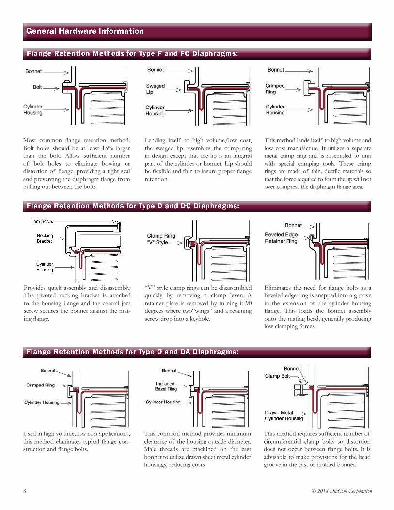
Flange Retention Methods for Type F and FC Diaphragms:
Flange Retention Methods for Type D and DC Diaphragms:
Flange Retention Methods for Type O and OA Diaphragms:
Most common flange retention method. Bolt holes should be at least 15% larger than the bolt. Allow sufficient number of bolt holes to eliminate bowing or distortion of flange, providing a tight seal and preventing the diaphragm flange from pulling out between the bolts.
Provides quick assembly and disassembly. The pivoted rocking bracket is attached to the housing flange and the central jam screw secures the bonnet against the mat-ing flange.
Used in high volume, low cost applications, this method eliminates typical flange con-struction and flange bolts.
Lending itself to high volume/low cost, the swaged lip resembles the crimp ring in design except that the lip is an integral part of the cylinder or bonnet. Lip should be flexible and thin to insure proper flange retention
“V” style clamp rings can be disassembled quickly by removing a clamp lever. A retainer plate is removed by turning it 90 degrees where two“wings” and a retaining screw drop into a keyhole.
This common method provides minimum clearance of the housing outside diameter. Male threads are machined on the cast bonnet to utilize drawn sheet metal cylinder housings, reducing costs.
This method lends itself to high volume and low cost manufacture. It utilizes a separate metal crimp ring and is assembled to unit with special crimping tools. These crimp rings are made of thin, ductile materials so that the force required to form the lip will not over-compress the diaphragm flange area.
Eliminates the need for flange bolts as a beveled edge ring is snapped into a groove in the extension of the cylinder housing flange. This loads the bonnet assembly onto the mating bead, generally producing low clamping forces.
This method requires sufficient number of circumferential clamp bolts so distortion does not occur between flange bolts. It is advisable to make provisions for the bead groove in the cast or molded bonnet.
9© 2018 DiaCom Corporation
General Hardware Information
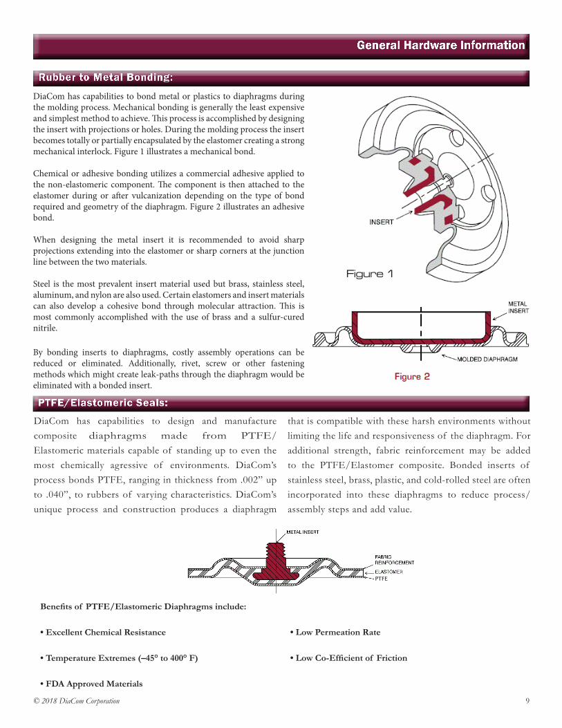
Rubber to Metal Bonding:
PTFE/Elastomeric Seals:
DiaCom has capabilities to design and manufacture composite diaphragms made from PTFE/Elastomeric materials capable of standing up to even the most chemically agressive of environments. DiaCom’s process bonds PTFE, ranging in thickness from .002” up to .040”, to rubbers of varying characteristics. DiaCom’s unique process and construction produces a diaphragm
that is compatible with these harsh environments without limiting the life and responsiveness of the diaphragm. For additional strength, fabric reinforcement may be added to the PTFE/Elastomer composite. Bonded inserts of stainless steel, brass, plastic, and cold-rolled steel are often incorporated into these diaphragms to reduce process/assembly steps and add value.
DiaCom has capabilities to bond metal or plastics to diaphragms during the molding process. Mechanical bonding is generally the least expensive and simplest method to achieve. This process is accomplished by designing the insert with projections or holes. During the molding process the insert becomes totally or partially encapsulated by the elastomer creating a strong mechanical interlock. Figure 1 illustrates a mechanical bond.
Chemical or adhesive bonding utilizes a commercial adhesive applied to the non-elastomeric component. The component is then attached to the elastomer during or after vulcanization depending on the type of bond required and geometry of the diaphragm. Figure 2 illustrates an adhesive bond. When designing the metal insert it is recommended to avoid sharp projections extending into the elastomer or sharp corners at the junction line between the two materials.
Steel is the most prevalent insert material used but brass, stainless steel, aluminum, and nylon are also used. Certain elastomers and insert materials can also develop a cohesive bond through molecular attraction. This is most commonly accomplished with the use of brass and a sulfur-cured nitrile.
By bonding inserts to diaphragms, costly assembly operations can be reduced or eliminated. Additionally, rivet, screw or other fastening methods which might create leak-paths through the diaphragm would be eliminated with a bonded insert.
Benefits of PTFE/Elastomeric Diaphragms include:
• Excellent Chemical Resistance
• Temperature Extremes (–45° to 400° F)
• FDA Approved Materials
• Low Permeation Rate
• Low Co-Efficient of Friction
Figure 1
PTFE
10 © 2018 DiaCom Corporation
Diaphragm Life Design Considerations
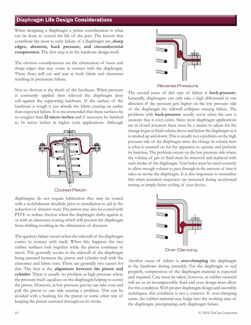
When designing a diaphragm a prime consideration is what can be done to extend the life of the part. The factors that contribute the most to early failure of a diaphragm are; sharp edges, abrasion, back pressure, and circumferential compression. The first step is in the hardware design itself.
The obvious considerations are the elimination of burrs and sharp edges that may come in contact with the diaphragm. These flaws will cut and tear at both fabric and elastomer resulting in premature failure.
Not so obvious is the finish of the hardware. When pressure is constantly applied then relieved the diaphragm does rub against the supporting hardware. If the surface of the hardware is rough it can abrade the fabric causing an earlier than expected failure. It is recommended that these surfaces be no rougher than 32 micro inches and if necessary be finished to 16 micro inches in higher cycle applications. Although
diaphragms do not require lubrication they may be coated with a molybdenum disulfide prior to installation to aid in the reduction of abrasive wear. The piston may also be coated with PTFE to reduce friction when the diaphragm shifts against it, or with an elastomer coating which will prevent the diaphragm from shifting resulting in the elimination of abrasion.
The quickest failure occurs when the sidewall of the diaphragm comes in contact with itself. When this happens the two rubber surfaces lock together while the piston continues to travel. This generally results in the sidewall of the diaphragm being jammed between the piston and cylinder wall with the elastomer and fabric torn. There are generally two causes for this. The first is the alignment between the piston and cylinder. There is usually no problem at high pressure where the pressure itself equalizes on the diaphragm helping to center the piston. However, at low pressure gravity can take over and pull the piston to one side causing a problem. This can be avoided with a bushing for the piston or some other way of keeping the piston centered throughout its stroke.
The second cause of this type of failure is back-pressure. Generally, diaphragms can only take a high differential in one direction If the pressure gets higher on the low pressure side of the diaphragm the sidewall collapses causing failure. The problems with back-pressure usually occur when the user is unaware that it even exists. Since most diaphragm applications are in closed actuators there must be a means to adjust for the change in gas or fluid volume above and below the diaphragm as it is stroked up and down. This is usually not a problem on the high pressure side of the diaphragm since the change in volume here is what is counted on for the apparatus to operate and perform its function. The problem occurs on the low pressure side where the volume of gas or fluid must be removed and replaced with each stroke of the diaphragm. Vent holes must be sized correctly to allow enough volume to pass through in the amount of time it takes to stroke the diaphragm. It is also important to remember this when actuation sequences are increased during accelerated testing or simply faster cycling of your device.
Another cause of failure is over-clamping the diaphragm in the hardware during assembly. For the diaphragm to seal properly, compression of the diaphragm material is expected and required. Care must be taken, however, as rubber material will act as an incompressible fluid and your design must allow for this condition. With proper diaphragm design and assembly techniques, this condition is not a concern. If over-clamping exists, the rubber material may bulge into the working area of the diaphragm, precipitating early diaphragm failure.
Cocked Piston
Over Clamping
Reverse Pressure
11© 2018 DiaCom Corporation
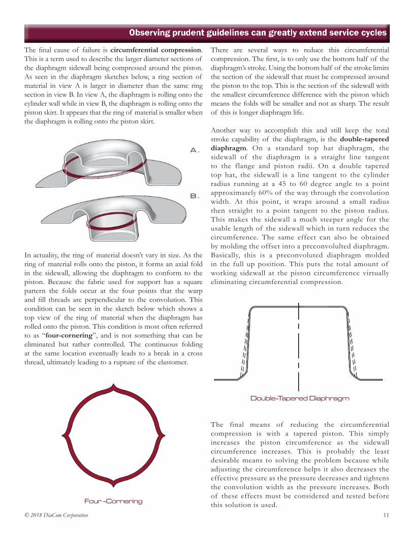
The final cause of failure is circumferential compression. This is a term used to describe the larger diameter sections of the diaphragm sidewall being compressed around the piston. As seen in the diaphragm sketches below, a ring section of material in view A is larger in diameter than the same ring section in view B. In view A, the diaphragm is rolling onto the cylinder wall while in view B, the diaphragm is rolling onto the piston skirt. It appears that the ring of material is smaller when the diaphragm is rolling onto the piston skirt.
In actuality, the ring of material doesn’t vary in size. As the ring of material rolls onto the piston, it forms an axial fold in the sidewall, allowing the diaphragm to conform to the piston. Because the fabric used for support has a square pattern the folds occur at the four points that the warp and fill threads are perpendicular to the convolution. This condition can be seen in the sketch below which shows a top view of the ring of material when the diaphragm has rolled onto the piston. This condition is most often referred to as “four-cornering”, and is not something that can be eliminated but rather controlled. The continuous folding at the same location eventually leads to a break in a cross thread, ultimately leading to a rupture of the elastomer.
There are several ways to reduce this circumferential compression. The first, is to only use the bottom half of the diaphragm’s stroke. Using the bottom half of the stroke limits the section of the sidewall that must be compressed around the piston to the top. This is the section of the sidewall with the smallest circumference difference with the piston which means the folds will be smaller and not as sharp. The result of this is longer diaphragm life.
Another way to accomplish this and still keep the total stroke capability of the diaphragm, is the double-tapered diaphragm. On a standard top hat diaphragm, the sidewall of the diaphragm is a straight line tangent to the flange and piston radii. On a double tapered top hat, the sidewall is a line tangent to the cylinder radius running at a 45 to 60 degree angle to a point approximately 60% of the way through the convolution width. At this point, it wraps around a small radius then straight to a point tangent to the piston radius. This makes the sidewall a much steeper angle for the usable length of the sidewall which in turn reduces the circumference. The same effect can also be obtained by molding the offset into a preconvolulted diaphragm. Basically, this is a preconvoluted diaphragm molded in the full up position. This puts the total amount of working sidewall at the piston circumference virtually eliminating circumferential compression.
The final means of reducing the circumferential compression is with a tapered piston. This simply increases the piston circumference as the sidewall circumference increases. This is probably the least desirable means to solving the problem because while adjusting the circumference helps it also decreases the effective pressure as the pressure decreases and tightens the convolution width as the pressure increases. Both of these effects must be considered and tested before this solution is used.
Observing prudent guidelines can greatly extend service cyclesl
Four -Cornering
B .
Double-Tapered Diaphragm
A .
12 © 2018 DiaCom Corporation
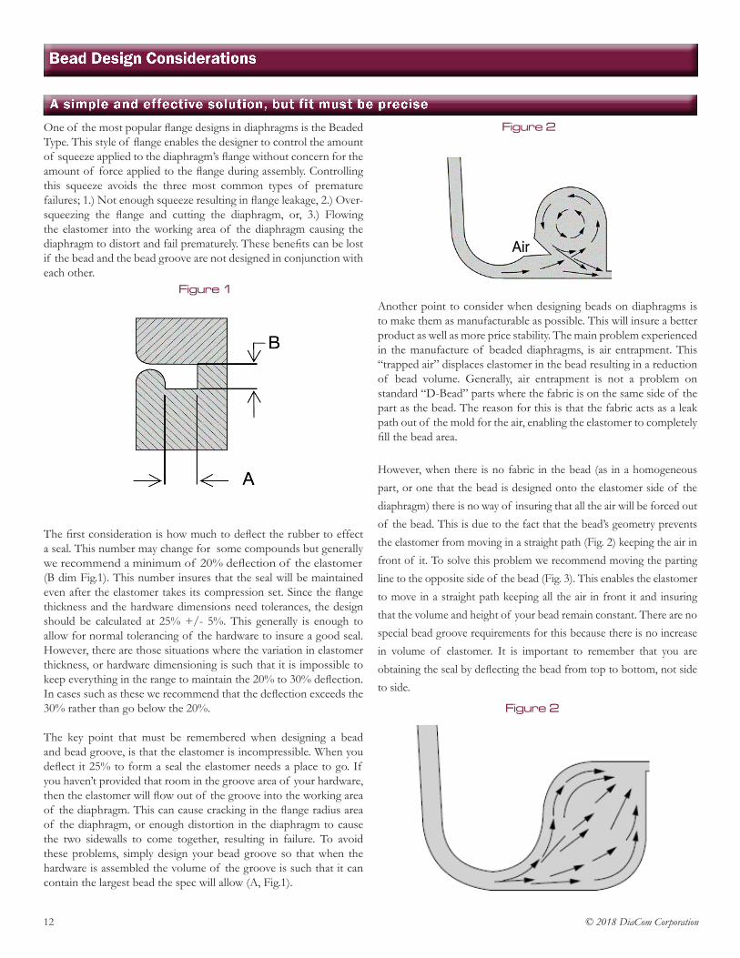
One of the most popular flange designs in diaphragms is the Beaded Type. This style of flange enables the designer to control the amount of squeeze applied to the diaphragm’s flange without concern for the amount of force applied to the flange during assembly. Controlling this squeeze avoids the three most common types of premature failures; 1.) Not enough squeeze resulting in flange leakage, 2.) Over-squeezing the flange and cutting the diaphragm, or, 3.) Flowing the elastomer into the working area of the diaphragm causing the diaphragm to distort and fail prematurely. These benefits can be lost if the bead and the bead groove are not designed in conjunction with each other.
The first consideration is how much to deflect the rubber to effect a seal. This number may change for some compounds but generally we recommend a minimum of 20% deflection of the elastomer (B dim Fig.1). This number insures that the seal will be maintained even after the elastomer takes its compression set. Since the flange thickness and the hardware dimensions need tolerances, the design should be calculated at 25% +/- 5%. This generally is enough to allow for normal tolerancing of the hardware to insure a good seal. However, there are those situations where the variation in elastomer thickness, or hardware dimensioning is such that it is impossible to keep everything in the range to maintain the 20% to 30% deflection. In cases such as these we recommend that the deflection exceeds the 30% rather than go below the 20%.
The key point that must be remembered when designing a bead and bead groove, is that the elastomer is incompressible. When you deflect it 25% to form a seal the elastomer needs a place to go. If you haven’t provided that room in the groove area of your hardware, then the elastomer will flow out of the groove into the working area of the diaphragm. This can cause cracking in the flange radius area of the diaphragm, or enough distortion in the diaphragm to cause the two sidewalls to come together, resulting in failure. To avoid these problems, simply design your bead groove so that when the hardware is assembled the volume of the groove is such that it can contain the largest bead the spec will allow (A, Fig.1).
Another point to consider when designing beads on diaphragms is to make them as manufacturable as possible. This will insure a better product as well as more price stability. The main problem experienced in the manufacture of beaded diaphragms, is air entrapment. This “trapped air” displaces elastomer in the bead resulting in a reduction of bead volume. Generally, air entrapment is not a problem on standard “D-Bead” parts where the fabric is on the same side of the part as the bead. The reason for this is that the fabric acts as a leak path out of the mold for the air, enabling the elastomer to completely fill the bead area.
However, when there is no fabric in the bead (as in a homogeneous part, or one that the bead is designed onto the elastomer side of the diaphragm) there is no way of insuring that all the air will be forced out of the bead. This is due to the fact that the bead’s geometry prevents the elastomer from moving in a straight path (Fig. 2) keeping the air in front of it. To solve this problem we recommend moving the parting line to the opposite side of the bead (Fig. 3). This enables the elastomer to move in a straight path keeping all the air in front it and insuring that the volume and height of your bead remain constant. There are no special bead groove requirements for this because there is no increase in volume of elastomer. It is important to remember that you are obtaining the seal by deflecting the bead from top to bottom, not side to side.
Bead Design Considerations
A simple and effective solution, but fit must be preciseFigure 2
Figure 1
Figure 2

13© 2018 DiaCom Corporation
Beadse
Beads can be added to the diaphragm in an almost infinite variety of shapes and sizes. However, there are many things to consider before adding beads to the diaphragm design. Not the least of which, is the impact on the cost of the diaphragm. Most beads are added to a diaphragm to be used as the sealing mechanism in the final application.
Beads are formed during the molding operation by flowing rubber into the mold cavity, filling the bead area while driving out the air. There are several limitations on bead design that must be considered due to this rubber flow. Bead location, shape, size, mold parting line, and etc. must all be carefully considered. The examples below illustrate some of the changes that can improve the quality of the diaphragms. These design changes are often driven by the location of the fabric reinforcement (the location of the fabric is shown below by the F symbol), but these design recommendations also apply to homogeneous (all-rubber) as well as double-coated diaphragms.
As Designed Recommended
14 © 2018 DiaCom Corporation
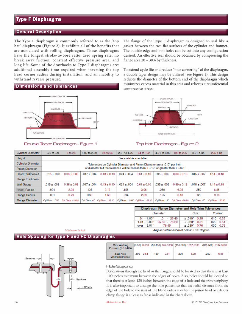
The Type F diaphragm is commonly referred to as the “top hat” diaphragm (Figure 2). It exhibits all of the benefits that are associated with rolling diaphragms. These diaphragms have the longest stroke-to-bore ratio, zero spring rate, no break away friction, constant effective pressure area, and long life. Some of the drawbacks to Type F diaphragms are: additional assembly time required when inverting the top head corner radius during installation, and an inability to withstand reverse pressure.
The flange of the Type F diaphragm is designed to seal like a gasket between the two flat surfaces of the cylinder and bonnet. The outside edge and bolt holes can be cut into any configuration desired. An effective seal should be obtained by compressing the flange area 20 – 30% by thickness.
To extend cycle life and reduce “four cornering” of the diaphragm, a double taper design may be utilized (see Figure 1). This design reduces the diameter of the bottom end of the diaphragm which minimizes excess material in this area and relieves circumferential compressive stress.
Type F Diaphragms
General Description
Dimensions and Tolerances
Double Taper Diaphragm - Figure 1 Top Hat Diaphragm - Figure 2
Hole Spacing for Type F and FC Diaphragms
Hole Spacing:Perforations through the head or the flange should be located so that there is at least .100 inches minimum between the edges of holes. Also, holes should be located so that there is at least .125 inches between the edge of a hole and the trim periphery. It is also important to arrange the hole pattern so that the radial distance from the edge of the hole to the start of the blend radius at either the piston head or cylinder clamp flange is at least as far as indicated in the chart above.
Millimeters in Red
Millimeters in Red
Head

15© 2018 DiaCom Corporation
Type F DiaphragmslAvailable Sizes
Millimeters in Red/*Metric Effective Pressure Area shown in Square Centimeters
16 © 2018 DiaCom Corporation
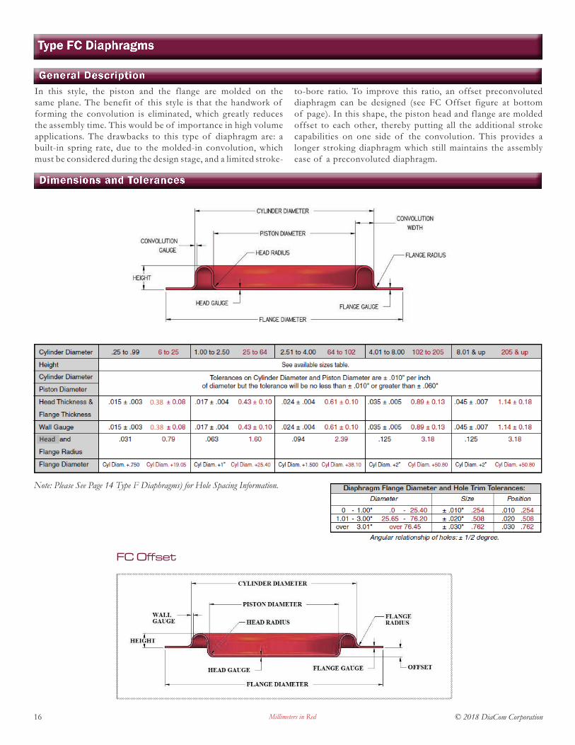
In this style, the piston and the flange are molded on the same plane. The benefit of this style is that the handwork of forming the convolution is eliminated, which greatly reduces the assembly time. This would be of importance in high volume applications. The drawbacks to this type of diaphragm are: a built-in spring rate, due to the molded-in convolution, which must be considered during the design stage, and a limited stroke-
to-bore ratio. To improve this ratio, an offset preconvoluted diaphragm can be designed (see FC Offset figure at bottom of page). In this shape, the piston head and flange are molded offset to each other, thereby putting all the additional stroke capabilities on one side of the convolution. This provides a longer stroking diaphragm which still maintains the assembly ease of a preconvoluted diaphragm.
Type FC Diaphragms
General Description
Dimensions and Tolerances
Note: Please See Page 14 Type F Diaphragms) for Hole Spacing Information.
FC Offset
Millimeters in Red
0.38
0.38Head

17© 2018 DiaCom Corporation
Type FC DIaphragmslAvailable Sizes
Millimeters in Red / *Metric Effective Pressure Area shown in Square Centimeters

18 © 2018 DiaCom Corporation
Type D Diaphragms
This style diaphragm is the same as the Type F in all respects except flange mounting. The parts are molded with what equates to half of an O-ring on the flange rather than a large flat surface. This O-Ring half fits into a groove machined into the cylinder half of the hardware. Sealing is achieved by squeezing
the bead into a properly-sized groove (see table at bottom of page). The cylinder and bonnet can then be designed to make positive contact when assembled, eliminating the need for a closely controlled assembly torque. It also reduces the overall diameter of the diaphragm, reducing the hardware diameter.
General Description
Dimensions and Tolerances
Hardware Recommendations
Millimeters in Red
19© 2018 DiaCom Corporation
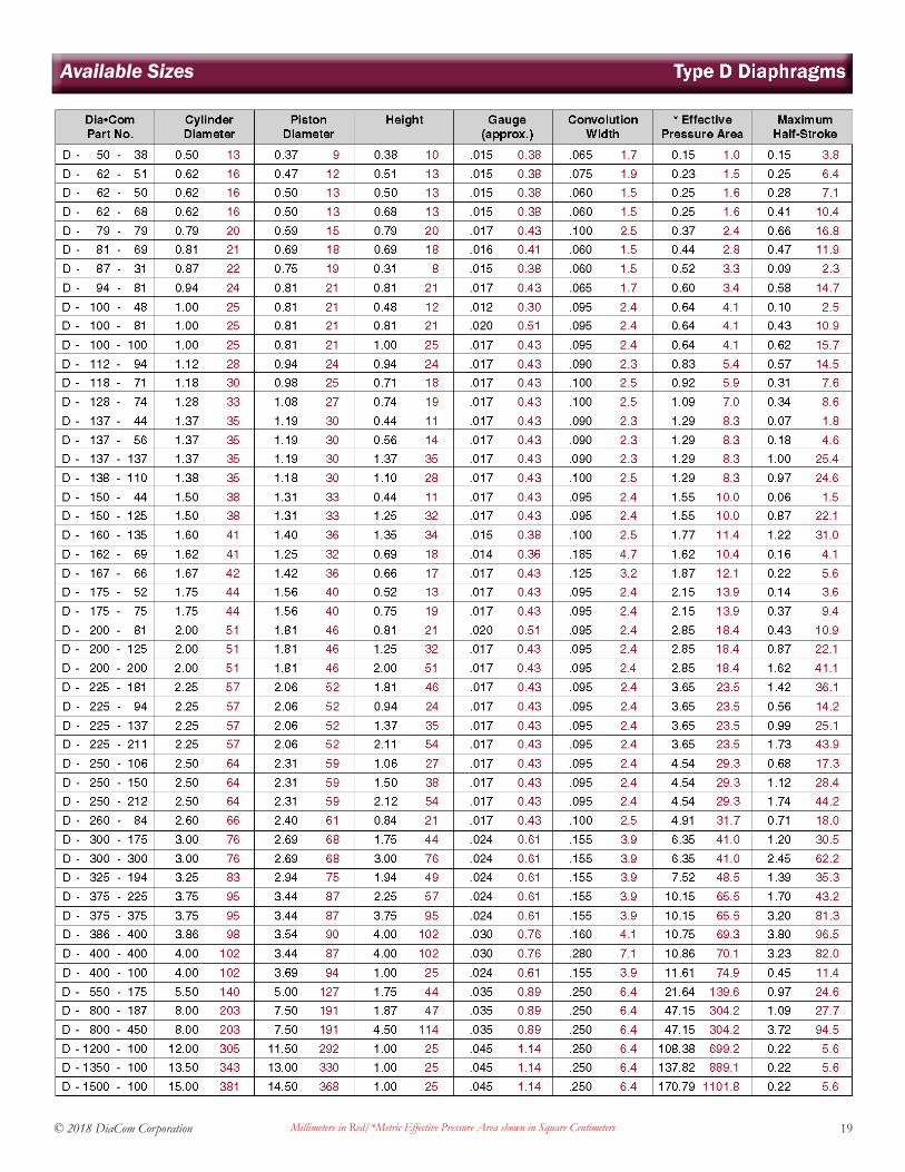
Type D DiaphragmslAvailable Sizes
Millimeters in Red/*Metric Effective Pressure Area shown in Square Centimeters
20 © 2018 DiaCom Corporation
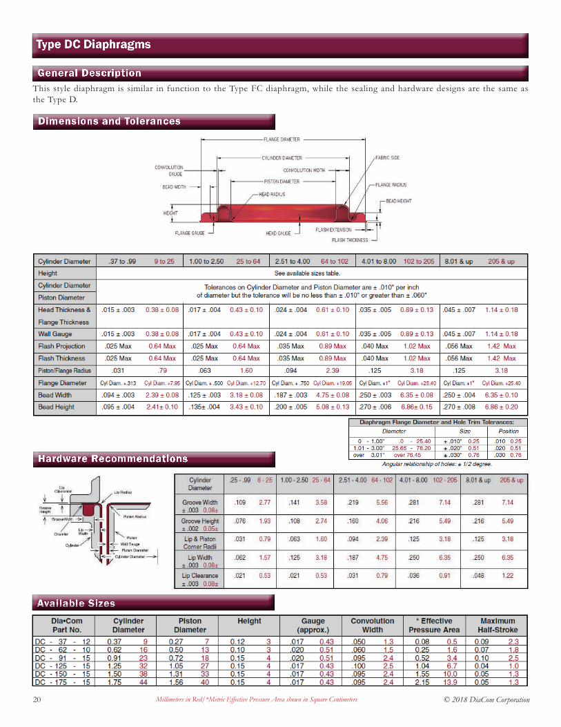
This style diaphragm is similar in function to the Type FC diaphragm, while the sealing and hardware designs are the same as the Type D.
General Description
Dimensions and Tolerances
Hardware Recommendations
Available Sizes
Type DC Diaphragms
Millimeters in Red/*Metric Effective Pressure Area shown in Square Centimeters
21© 2018 DiaCom Corporation
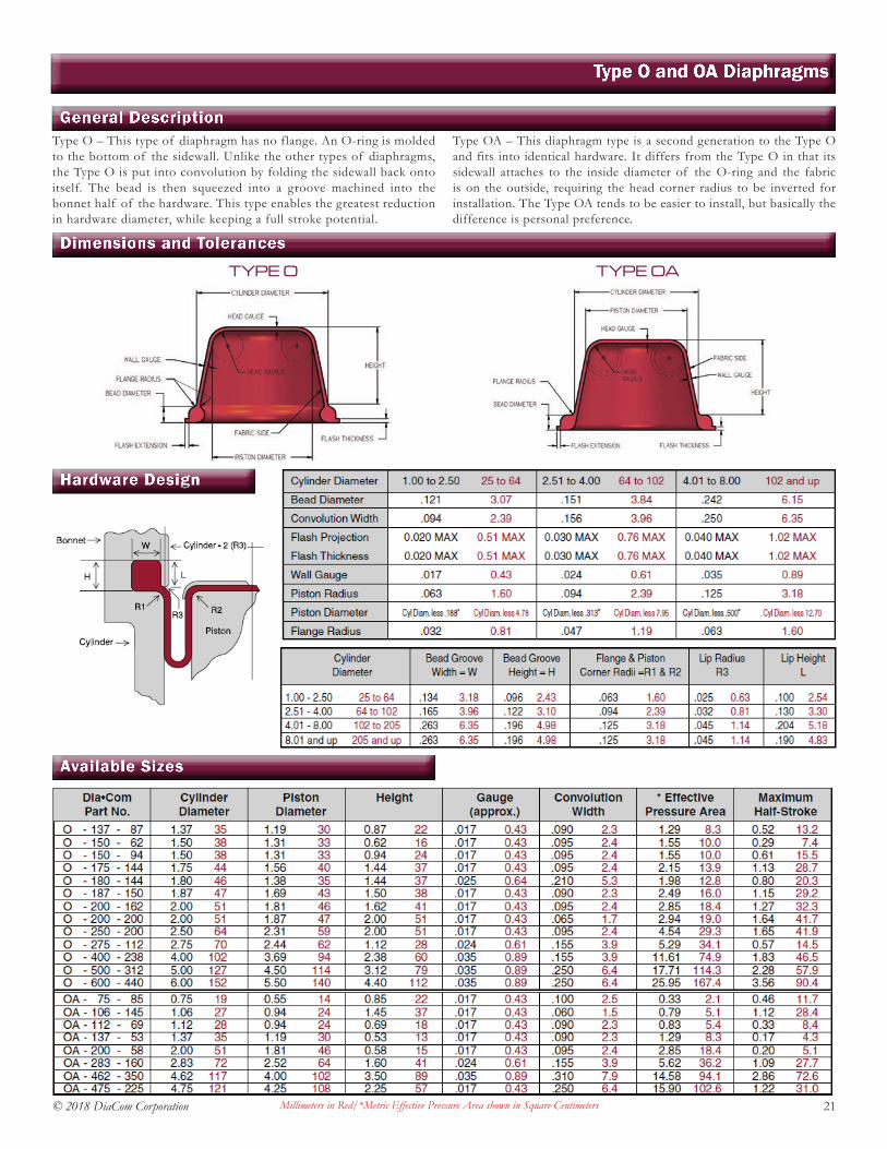
Type O – This type of diaphragm has no flange. An O-ring is molded to the bottom of the sidewall. Unlike the other types of diaphragms, the Type O is put into convolution by folding the sidewall back onto itself. The bead is then squeezed into a groove machined into the bonnet half of the hardware. This type enables the greatest reduction in hardware diameter, while keeping a full stroke potential.
Type OA – This diaphragm type is a second generation to the Type O and fits into identical hardware. It differs from the Type O in that its sidewall attaches to the inside diameter of the O-ring and the fabric is on the outside, requiring the head corner radius to be inverted for installation. The Type OA tends to be easier to install, but basically the difference is personal preference.
General Description
Dimensions and Tolerances
Type O and OA Diaphragmsl
Hardware Design
Available Sizes
Millimeters in Red/*Metric Effective Pressure Area shown in Square Centimeters
TYPE O TYPE OA

22 © 2018 DiaCom Corporation
Type OB diaphragms have a rectangular bead molded inside their cylinder wall. This design requires the smallest hardware diameter of any diaphragm type. The Type OB diaphragm has only half the stroke capability of other diaphragm styles of the
same height. Because the clamping and sealing of this style diaphragm is against the inside wall of the cylinder, the stroke is restricted to the lower half of the diaphragm.
General Description
Dimensions and TolerancesHardware Design
Available Sizes
Type OB Diaphragms
Stamped Retainer Plate Sealing Via
Axial Compression
Cast Machined Retainer Plate Sealing Via
Radial Compression
Millimeters in Red/*Metric Effective Pressure Area shown in Square Centimeters

23© 2018 DiaCom Corporation
This diaphragm type, commonly referred to as dish-shaped, has a sidewall that slopes gradually from the cylinder to the piston. This diaphragm is designed to be f lexed in both directions to its full height. It may be double-
coated to take pressure in both directions. Due to its wide convolution and gradual sidewall slope, the total travel and ability to withstand high pressures are limited. The effective pressure also varies through its stroke.
General Description
Dimensions and Tolerances
Type P Diaphragmsl
Available Sizes
Elastomer & Fabric Data
Genera l l y, f abr i c re in forcement i s r equ i red when pressure d i f fe rent i a l s exceed 5 ps i ac ross the d iaphragm. Some app l i ca t ions may requ i re e l a s tomer ic coa t ings on both s ides of the f abr i c. These mater i a l s a re ava i l ab le f rom s tock . Due to the many app l i ca t ion var i ab les, i t i s r ecommended tha t a DiaCom representa t ive be consu l ted to ensure proper se l ec t ion . The char t on pag e 24 l i s t s some of DiaCom’s common fabr i c s ty l e s, a s we l l a s some g enera l phys i ca l charac te r i s t i c s o f va r ious f abr i c f ibers.
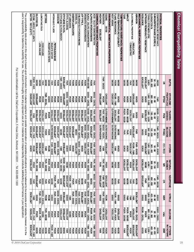
The chart on page 25 lists common elastomers, some physical properties, and compatibility to common chemicals. Other DiaCom specialty elastomer compounds are available. These include FDA, NSF, and UL-approved compounds used in potable water, food, drug, propane and natural gas applications. Additionally, elastomeric silicone/fluorosilicone blends are available for automotive use. This is a general chart and is in no way intended as the final guide to material selection. Contact a DiaCom representative for proper elastomer selection.
Fabric Data Elastomer Data
Millimeters in Red/*Metric Effective Pressure Area shown in Square Centimeters
24 © 2018 DiaCom Corporation
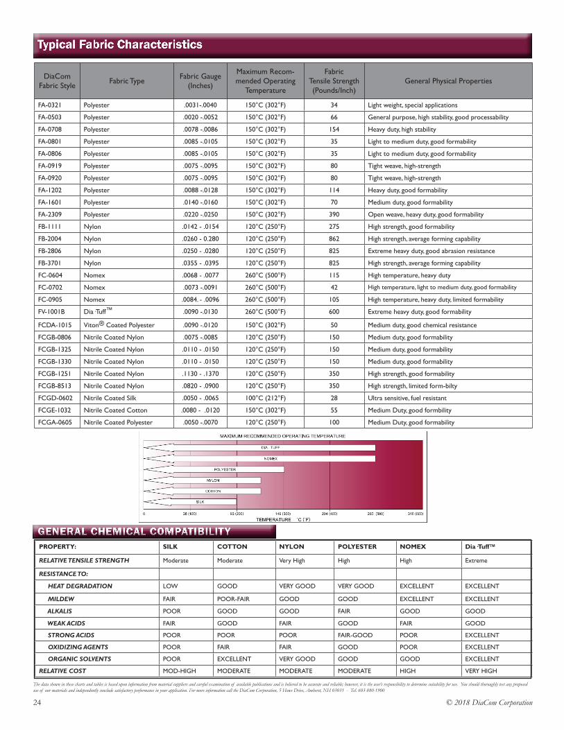
Typical Fabric Characteristics
The data shown in these charts and tables is based upon information from material suppliers and careful examination of available publications and is believed to be accurate and reliable; however, it is the user’s responsibility to determine suitability for use. You should thoroughly test any proposed use of our materials and independently conclude satisfactory performance in your application. For more information call the DiaCom Corporation, 5 Howe Drive, Amherst, NH 03031 - Tel. 603-880-1900
DiaCom Fabric Style Fabric Type Fabric Gauge
(Inches)
Maximum Recom-mended Operating
Temperature
Fabric Tensile Strength (Pounds/Inch)
General Physical Properties
FA-0321 Polyester .0031-.0040 150°C (302°F) 34 Light weight, special applications
FA-0503 Polyester .0020 -.0052 150°C (302°F) 66 General purpose, high stability, good processability
FA-0708 Polyester .0078 -.0086 150°C (302°F) 154 Heavy duty, high stability
FA-0801 Polyester .0085 -.0105 150°C (302°F) 35 Light to medium duty, good formability
FA-0806 Polyester .0085 -.0105 150°C (302°F) 35 Light to medium duty, good formability
FA-0919 Polyester .0075 -.0095 150°C (302°F) 80 Tight weave, high-strength
FA-0920 Polyester .0075 -.0095 150°C (302°F) 80 Tight weave, high-strength
FA-1202 Polyester .0088 -.0128 150°C (302°F) 114 Heavy duty, good formability
FA-1601 Polyester .0140 -.0160 150°C (302°F) 70 Medium duty, good formability
FA-2309 Polyester .0220 -.0250 150°C (302 °F) 390 Open weave, heavy duty, good formability
FB-1111 Nylon .0142 - .0154 120 °C (250°F) 275 High strength, good formability
FB-2004 Nylon .0260 - 0.280 120 °C (250°F) 862 High strength, average forming capability
FB-2806 Nylon .0250 - .0280 120 °C (250°F) 825 Extreme heavy duty, good abrasion resistance
FB-3701 Nylon .0355 - .0395 120 °C (250°F) 825 High strength, average forming capability
FC-0604 Nomex .0068 - .0077 260°C (500 °F) 115 High temperature, heavy duty
FC-0702 Nomex .0073 -.0091 260°C (500 °F) 42 High temperature, light to medium duty, good formability
FC-0905 Nomex .0084. - .0096 260°C (500 °F) 105 High temperature, heavy duty, limited formability
FV-1001B Dia·Tuff™ .0090 -.0130 260°C (500 °F) 600 Extreme heavy duty, good formability
FCDA-1015 Viton® Coated Polyester .0090 -.0120 150°C (302°F) 50 Medium duty, good chemical resistance
FCGB-0806 Nitrile Coated Nylon .0075 -.0085 120°C (250 °F) 150 Medium duty, good formability
FCGB-1325 Nitrile Coated Nylon .0110 - .0150 120°C (250 °F) 150 Medium duty, good formability
FCGB-1330 Nitrile Coated Nylon .0110 - .0150 120°C (250 °F) 150 Medium duty, good formability
FCGB-1251 Nitrile Coated Nylon .1130 - .1370 120°C (250 °F) 350 High strength, good formability
FCGB-8513 Nitrile Coated Nylon .0820 - .0900 120°C (250 °F) 350 High strength, limited form-bilty
FCGD-0602 Nitrile Coated Silk .0050 - .0065 100°C (212 °F) 28 Ultra sensitive, fuel resistant
FCGE-1032 Nitrile Coated Cotton .0080 - .0120 150°C (302 °F) 55 Medium Duty, good formbility
FCGA-0605 Nitrile Coated Polyester .0050 -.0070 120°C (250 °F) 100 Medium Duty, good formability
PROPERTY: SILK COTTON NYLON POLYESTER NOMEX Dia·Tuff™
RELATIVE TENSILE STRENGTH Moderate Moderate Very High High High Extreme
RESISTANCE TO:
HEAT DEGRADATION LOW GOOD VERY GOOD VERY GOOD EXCELLENT EXCELLENT
MILDEW FAIR POOR-FAIR GOOD GOOD EXCELLENT EXCELLENT
ALKALIS POOR GOOD GOOD FAIR GOOD GOOD
WEAK ACIDS FAIR GOOD FAIR GOOD FAIR GOOD
STRONG ACIDS POOR POOR POOR FAIR-GOOD POOR EXCELLENT
OXIDIZING AGENTS POOR FAIR FAIR GOOD POOR EXCELLENT
ORGANIC SOLVENTS POOR EXCELLENT VERY GOOD GOOD GOOD EXCELLENT
RELATIVE COST MOD-HIGH MODERATE MODERATE MODERATE HIGH VERY HIGH
GENERAL CHEMICAL COMPATIBILITY
25© 2018 DiaCom Corporation
Chemical Com
patibility Table

26 © 2018 DiaCom Corporation
Diaphragm Seals
The information shown is based upon information from material suppliers and careful examination of available publications and is believed to be accurate and reliable; however, it is the user’s responsibility to determine suitability for use. You should thoroughly test any proposed use of our materials and independently conclude satisfactory performance in your application.
5 Howe Drive Amherst, NH 03031 USAPhone: 800.632.5681 603.880.1900 Fax: 603.880.7616
Internet: www.diacom.com Email: [email protected]
DiaCom Corporation, an ISO 9001 and AS9100 certified company, is a recognized leader in the design, manufacture and application of innovative, high performance molded diaphragm seals. DiaCom serves a variety of markets world-wide including industrial, automotive, aerospace, food processing, water controls, medical instrumentation, appliances and others. DiaCom offers state-of-the-art diaphragms designed for cost effectiveness, ease of installation, durability, and high performance characteristics.
Thank you for your request for engineering assistance. Answers to the following questions will provide our Engineering department with information to assist in the analysis of your specific application. Please make sure to provide as much information as available. Where possible, please provide prints, layouts, or sketches of the proposed diaphragm and installation.
Type of mounting inches Cylinder Bore Diameter inches
Piston Diameter inches Height inchesUp-Stroke inches Minimum Operating Temperature º FDown-Stroke* inches Normal Operating Temperature ºFTotal Stroke inches Maximum Temperature ºFMinimum Pressure psi Time Interval at High Temperature:
Normal Pressure psi
Maximum Pressure** psi * Stroke as measured from Flange
Reverse Pressure psi ** Operating and Surge
Pressure Differential: psi
Fluid or gas in contact with Diaphragm on High Pressure Side: ________________________________________________Fluid or Gas in contact with Diaphragm on Low Pressure Side: ________________________________________________Estimated # of Cycles Required for Satisfactory Performance: ________________ Approximate Cycle Rate: ____________Trim & Perforation Requirements: ______________________________________________________________________Submit sketch or drawing if special trim/perforation requirements.)Annual Quantity Requirements: ____________________ Delivery/Release Requirements: ___________________________Customer Part or Print Number: ___________________
(If this is a current production part, please indicate any quality or performance problems you are encountering. If appropriate, submit a sample part for Engineering evaluation.)
Please list any special requirements or environmental considerations not listed above: ______________________________________________________________________________________________________________________________________________________________________________Please Print Below:
Date:Name:_____________________________________________ Title: _____________________________ Company: __________________________________________ Phone: ____________________________Street Address: ______________________________________ Fax: ______________________________City: ___________________________ State: _______ Country: _________________
Diaphragm Design & Manufacturing Leader
DIA·COM CORPORATIONThe Diaphragm Company
Online Guidebook: www.diacom.com
Application Data Form

27© 2018 DiaCom Corporation
The DiaCom Advantagel
In-House DesignComputer Aided Drafting electronically enhances DiaCom’s abilities to provide accurate customer tooling designs on a timely basis. DiaCom’s application engineers routinely assist customers in the design of 3-D drawings, standard, or special diaphragm. We are able to accept most popular formats of CAD drawings, including: Solid Edge, STEP, IGES, DXF and others. DiaCom uses only high strength steel for production and prototype molds. DiaCom’s internal tool shop has complete CNC machining capabilities that allows for quick turnaround on prototype and production tooling.
Quality Management
DiaCom’s Quality Systems are certified to AS-9100 Quality Management System, an International
Standard developed to assure customer satisfaction. AS-9100 uses a process approach when developing,
implementing, and improving the effectiveness of a quality management system. Diacom’s “DiaTrac”
system enables 100% lot traceability. SPC, FMEA’s, 8-D analysis, Process Control Plans, and Process
Capability Studies are routinely used in accordance with manufacturing requirements. Zero-defect
sampling and continual in-process quality audits insure dimensional and material integrity.
State-of-the-Art Production Facilities
Microprocessor-controlled production presses designed specifically for the production of fabric-reinforced and homogeneous elastomeric diaphragms. Our new production presses are built with high-strength components. The microprocessors closely control the vulcanization process, thus assuring precise, repeatable control of the molding process. The result is high quality, low cost diaphragm production. DiaCom utilizes unique compression and transfer molding processes to maximize efficiencies and insure the dimensional integrity of each part.
Engineering Experience
DiaCom Engineers routinely work with our customer engineering personnel to transform application concepts first into fully functioning prototypes, and ultimately, into production units. Our experience and background allow us to cost-effectively provide a diaphragm that meets or exceeds all customer’s diaphragm expectations. Using Auto-Cad drafting software, we are able to communicate electronically with our customers to accelerate the design process. Existing diaphragm applications sometimes do not perform as well as intended. Our technical staff is available as an aid to our customers to analyze performance issues, offer hardware recommendations, and to assist in root cause analysis and the implementation of permanent corrective actions.
In-House Rubber Materials Laboratory
Constantly striving to improve existing applications, meeting the demands of new programs, and trouble shooting application issues, DiaCom has established a Rubber Materials Lab that gives us significant rubber testing capabilities. Using ASTM standard procedures, we are able to obtain physical properties, such as, tensile strength, elongation, modulus, durometer, tear strength, compression set, and rheology data, such as viscosity, cure times, scorch date and etc. We are also capable of running a variety of chemical compatibility testing, heat aging, volume swells, etc. using ASTM standard testing procedures, and we can run customer-specific tests. DiaCom can custom formulate materials to meet virtually any application environment. Combining this test capability with our technical expertise allows us to provide materials that meet customer specifications, ASTM material call-out and other certification bodies, such as UL or NSF.
Corporate Headquarters:
5 Howe Drive Amherst, NH 03031 USA
Phone (US Only): 800.632.5681 603.880.1900 Fax: 603.880.7616
Internet: www.diacom.com Email: [email protected]
The Diaphragm Company
Molded Diaphragms: Ideal solutions to tough sealing problems.
The information contained herein is believed to be reliable, but no representations, guarantees or warranties of any kind are made as to its accuracy, suitability for particular applications or the results to be obtained therefrom. Nothing contained herein is to be considered as permission, recommendation, nor as an inducement to practice any patented invention without permission of the patent owner.


![DOWNTOWN ALLEY DESIGN GUIDEBOOK · The purpose of the Downtown Alley Design Guidebook [“Guidebook”] is to provide recommendations for possible improvements that can be implemented](https://static.fdocuments.us/doc/165x107/5b87cc3d7f8b9a301e8c0644/downtown-alley-design-guidebook-the-purpose-of-the-downtown-alley-design-guidebook.jpg)