Diagnose Repeater e
204
Preface, Contents Product Overview 1 Functions 2 Configuration Options 3 Installation 4 Wiring 5 Commissioning 6 Diagnostics 7 Technical Specifications 8 Appendices Order Numbers A Dimension Drawings B User Questions C Glossary, Index SIMATIC Diagnostic Repeater for PROFIBUS-DP Manual This manual has the order number: 6ES7972-0AB00-8BA0 Edition 12/2002 A5E00103899-02 The following supplements are part of this documentation: No. Designation Drawing number Edition 1 Product information A5E00352937-01 10/2004
-
Upload
tetsusaiga -
Category
Documents
-
view
225 -
download
0
Transcript of Diagnose Repeater e

7/31/2019 Diagnose Repeater e
http://slidepdf.com/reader/full/diagnose-repeater-e 1/204
Preface, Contents
Product Overview 1
Functions 2
Configuration Options 3
Installation 4
Wiring 5
Commissioning 6
Diagnostics 7
Technical Specifications 8
Appendices
Order Numbers A
Dimension Drawings BUser Questions C
Glossary, Index
SIMATIC
Diagnostic Repeaterfor PROFIBUS-DP
Manual
This manual has the order number:6ES7972-0AB00-8BA0
Edition 12/2002A5E00103899-02
The following supplements are part of this documentation:
No. Designation Drawing number Edition
1 Product information A5E00352937-01 10/2004

7/31/2019 Diagnose Repeater e
http://slidepdf.com/reader/full/diagnose-repeater-e 2/204
Copyright © Siemens AG 2001-2002 All rights reserved
The reproduction, transmission or use of this document or itscontents is not permitted without express written authority.Offenders will be liable for damages. All rights, including rightscreated by patent grant or registration of a utility model or design,are reserved.
Siemens AGBereich Automation and DrivesGeschaeftsgebiet Industrial Automation SystemsPostfach 4848, D- 90327 Nuernberg
Disclaimer of Liability
We have checked the contents of this manual for agreement withthe hardware and software described. Since deviations cannot beprecluded entirely, we cannot guarantee full agreement. However,the data in this manual are reviewed regularly and any necessarycorrections included in subsequent editions. Suggestions forimprovement are welcomed.
©Siemens AG 2002Technical data subject to change.
Siemens Aktiengesellschaft A5E00103899-02
Safety Guidelines
This manual contains notices intended to ensure personal safety, as well as to protect the products and
connected equipment against damage. These notices are highlighted by the symbols shown below and
graded according to severity by the following texts:
!Dangerindicates that death, severe personal injury or substantial property damage will result if proper
precautions are not taken.
!Warningindicates that death, severe personal injury or substantial property damage can result if properprecautions are not taken.
!Cautionindicates that minor personal injury can result if proper precautions are not taken.
Cautionindicates that property damage can result if proper precautions are not taken.
Noticedraws your attention to particularly important information on the product, handling the product, or to aparticular part of the documentation.
Qualified Personnel
Only qualified personnel should be allowed to install and work on this equipment. Qualified persons are
defined as persons who are authorized to commission, to ground and to tag circuits, equipment, and
systems in accordance with established safety practices and standards.
Correct Usage
Note the following:
!Warning
This device and its components may only be used for the applications described in the catalog or the
technical description, and only in connection with devices or components from other manufacturers
which have been approved or recommended by Siemens.
This product can only function correctly and safely if it is transported, stored, set up, and installedcorrectly, and operated and maintained as recommended.
Trademarks
SIMATIC®, SIMATIC HMI® and SIMATIC NET® are registered trademarks of SIEMENS AG.
Third parties using for their own purposes any other names in this document which refer to trademarks might
infringe upon the rights of the trademark owners.

7/31/2019 Diagnose Repeater e
http://slidepdf.com/reader/full/diagnose-repeater-e 3/204
Diagnostic Repeater for PROFIBUS-DPA5E00103899-02 iii
Preface
Purpose of the manual
This manual provides an overview of the diagnostic repeater for PROFIBUS-DP. Itsupports you in the configuration, installation and commissioning.
It is intended for persons working in the fields of configuring, commissioning andservicing automation systems.
Required knowledge
A general knowledge of automation technology is required in order to understandthe manual.
Validity of the manual
The manual is valid for the diagnostic repeater for PROFIBUS-DP with the ordernumber 6ES7 972-0AB01-0XA0.
Changes since the previous version
The following chapters have been revised and added to since the previous edition
of the manual "Diagnostic Repeater for PROFIBUS-DP":• Chapter 2, "Functions"
• Chapter 3, "Configuration Options"
• Chapter 7, "Diagnostics"
• Chapter 8, "Technical Specifications"
Note: You can identify the previous version of this manual by its number in thefooter on each page: A5E00103899-01.
The number now is: A5E00103899-02.

7/31/2019 Diagnose Repeater e
http://slidepdf.com/reader/full/diagnose-repeater-e 4/204
Preface
Diagnostic Repeater for PROFIBUS-DPiv A5E00103899-02
Approvals
See Chapter 8.1, Standards and Approvals.
CE marking
See Chapter 8.1, Standards and Approvals.
Marking for Australia (C-Tick Mark)
See Chapter 8.1, Standards and Approvals.
Standards
See Chapter 8.1, Standards and Approvals.

7/31/2019 Diagnose Repeater e
http://slidepdf.com/reader/full/diagnose-repeater-e 5/204
Preface
Diagnostic Repeater for PROFIBUS-DPA5E00103899-02 v
Guide
In order to facilitate rapid access to special information the manual has thefollowing access aids:
• The manual begins with a table of contents.
• The chapters contain intermediate headlines which provide an overview of thecontents of the section.
• At the end of the appendix there is a glossary which defines the technicalterms used in the manual.
• At the end of the manual there is a detailed index which allows you rapidaccess to the desired information.
• You can get direct access to information on the diagnostic repeater on theInternet athttp://www.siemens.com/Diagnostic-Repeater
Recycling and disposal
The diagnostic repeater is low in contaminants and can thus be recycled. Torecycle and dispose of your old equipment in an environmentally friendly manner,contact a company that is certified to dispose of electronic waste.
Further support
Please contact your local Siemens representative if you have any queries aboutthe products described in this manual.
http://www.siemens.com/automation/partner
Training center
We offer corresponding courses to help familiarize you with the SIMATIC S7 PLC.Please contact your regional training center or the central training center inD 90327 Nuremberg.
Phone: +49 (911) 895-3200.
Internet: http://www.sitrain.com

7/31/2019 Diagnose Repeater e
http://slidepdf.com/reader/full/diagnose-repeater-e 6/204
Preface
Diagnostic Repeater for PROFIBUS-DPvi A5E00103899-02
A&D Technical Support
Worldwide, available 24 hours a day:
Beijing
Nuernberg
Johnson City
Worldwide (Nuernberg)
Technical Support
24 hours a day, 365 days a year
Phone: +49 (0) 180 5050-222
Fax: +49 (0) 180 5050-223E-Mail: adsupport@
siemens.com
GMT: +1:00
Europe / Africa (Nuernberg)
Authorization
Local time: Mon.-Fri. 8:00 AMto 5:00 PM
Phone: +49 (0) 180 5050-222
Fax: +49 (0) 180 5050-223
E-Mail: adsupport@
siemens.com
GMT: +1:00
United States (Johnson City)
Technical Support andAuthorization
Local time: Mon.-Fri. 8:00 AMto 5:00 PM
Phone: +1 (0) 423 262 2522
Fax: +1 (0) 423 262 2289
E-Mail: simatic.hotline@
sea.siemens.com
GMT: -5:00
Asia / Australia (Beijing)
Technical Support andAuthorization
Local time: Mon.-Fri. 8:00 AMto 5:00
Phone: +86 10 64 75 75 75
Fax: +86 10 64 74 74 74
E-Mail: adsupport.asia@
siemens.com
GMT: +8:00
The languages of the SIMATIC Hotlines and the authorization hotline are generally German and English.

7/31/2019 Diagnose Repeater e
http://slidepdf.com/reader/full/diagnose-repeater-e 7/204
Preface
Diagnostic Repeater for PROFIBUS-DPA5E00103899-02 vii
Service & Support on the Internet
In addition to our documentation, we offer our Know-how online on the internet at:
http://www.siemens.com/automation/service&support
where you will find the following:
• The newsletter, which constantly provides you with up-to-date information onyour products.
• The right documents via our Search function in Service & Support.
• A forum, where users and experts from all over the world exchange theirexperiences.
• Your local representative for Automation & Drives via our representativesdatabase.
• Information on field service, repairs, spare parts and more under "Services".

7/31/2019 Diagnose Repeater e
http://slidepdf.com/reader/full/diagnose-repeater-e 8/204
Preface
Diagnostic Repeater for PROFIBUS-DPviii A5E00103899-02
7/31/2019 Diagnose Repeater e
http://slidepdf.com/reader/full/diagnose-repeater-e 9/204
Diagnostic Repeater for PROFIBUS-DPA5E00103899-02 iii
Contents
1 Product Overview 1-1
1.1 What are distributed I/O devices?.....................................................................1-11.2 What is a diagnostic repeater?..........................................................................1-31.2.1 Functions and range of applications .................................................................1-31.2.2 View of the diagnostic repeater.........................................................................1-51.2.3 How the diagnostic repeater works...................................................................1-71.3 Enhancements and compatibility with the predecessor module.....................1-10
2 Functions 2-1
2.1 Repeater function..............................................................................................2-1
2.2 Topology data: bus topology and topology table ..............................................2-22.3 Diagnostic buffer ...............................................................................................2-22.4 Statistics buffer..................................................................................................2-32.5 Time ..................................................................................................................2-32.5.1 Setting the time .................................................................................................2-32.5.2 Time record format............................................................................................2-42.6 Identification data..............................................................................................2-52.7 Monitoring functions for the clocked PROFIBUS bus system...........................2-6
3 Configuration Options 3-1
3.1 Design guidelines for diagnostic repeaters.......................................................3-13.1.1 PROFIBUS networks ........................................................................................3-13.1.2 PROFIBUS components ...................................................................................3-2
3.1.3 Bus connectors and cables...............................................................................3-33.1.4 Line length and cascading depth ......................................................................3-53.1.5 Spur lines ..........................................................................................................3-63.1.6 Only one measuring circuit at a segment..........................................................3-73.1.7 Arrangement of the DP master .........................................................................3-83.1.8 Example configuration.....................................................................................3-103.2 Limitations when using components with repeater function ...........................3-123.2.1 Network design with an RS 485 repeater .......................................................3-153.2.2 Network design with an Optical Link Module (OLM).......................................3-173.3 Recommendations for structuring a new plant................................................3-193.4 Use in an existing plant ...................................................................................3-20
4 Installation 4-1
4.1 Mounting rules...................................................................................................4-14.2 Mounting the diagnostic repeater on a mounting rail for S7-300......................4-24.3 Mounting the diagnostic repeater on a DIN rail.................................................4-3
5 Wiring 5-1
5.1 Basis..................................................................................................................5-15.2 Connecting the supply voltage..........................................................................5-25.3 Connecting the PROFIBUS cables...................................................................5-35.4 Block diagram of the diagnostic repeater..........................................................5-5
7/31/2019 Diagnose Repeater e
http://slidepdf.com/reader/full/diagnose-repeater-e 10/204
Contents
Diagnostic Repeater for PROFIBUS-DPiv A5E00103899-02
6 Commissioning 6-1
6.1 Addressing ........................................................................................................6-16.2 Configuration.....................................................................................................6-36.2.1 Configuration for standard operation.................................................................6-46.2.2 Configuring the monitoring functions for the clocked PROFIBUS bus system.6-56.3 Parameter assignment with STEP 7 .................................................................6-66.3.1 Parameterizing the diagnostic message frame length......................................6-66.3.2 Parameter assignment when using components with a repeater function .......6-76.3.3 Parameter assignment of the monitoring functions for the clocked
PROFIBUS bus system.....................................................................................6-76.3.4 Parameter assignment of DP interrupt mode in STEP 7 ..................................6-76.4 Commissioning: Determining the topology .......................................................6-8
7 Diagnostics 7-1
7.1 Overview ...........................................................................................................7-17.1.1 Diagnosis through LED display.........................................................................7-27.1.2 Diagnosis with STEP 7 and COM PROFIBUS..................................................7-47.2 Structure of the diagnosis .................................................................................7-5
7.2.1 Structure of the slave diagnosis ........................................................................7-57.2.2 Node status 1 to 3 .............................................................................................7-67.2.3 Master PROFIBUS address ..............................................................................7-77.2.4 Manufacturer identifier ......................................................................................7-87.2.5 Structure of the module diagnosis.....................................................................7-87.2.6 Structure of the device-specific diagnosis.........................................................7-97.2.7 Monitoring function of the clocked PROFIBUS bus system............................7-137.3 Reading data out in the user program ............................................................7-147.3.1 Topology table.................................................................................................7-147.3.2 Diagnostic buffer .............................................................................................7-177.3.3 Statistics buffer................................................................................................7-207.4 Topology display in STEP 7 ............................................................................7-247.4.1 Topology data: bus topology and topology table ............................................7-24
7.4.2 Diagnostic buffer .............................................................................................7-267.4.3 Statistics buffer................................................................................................7-287.4.4 Error messages...............................................................................................7-307.5 Diagnostic messages and fault elimination.....................................................7-317.5.1 Design guidelines not observed......................................................................7-317.5.2 Message frame error rate in the segment is critical ........................................7-337.5.3 Break in the signal wire A or B........................................................................7-347.5.4 Short circuit in the signal wire A and B or short circuit in the signal wire
A or B to screen...............................................................................................7-347.5.5 Terminator.......................................................................................................7-357.5.6 Segment of diagnostic repeater de-activated automatically ...........................7-357.5.7 Fault cause or fault location not clear .............................................................7-367.5.8 Fault cannot be evaluated...............................................................................7-36
7.5.9 Topology determination not possible ..............................................................7-378 Technical Specifications 8-1
8.1 Standards and approvals ..................................................................................8-18.1.1 Electromagnetic compatibility of the diagnostic repeater..................................8-48.1.2 Mechanical and climatic ambient conditions for transportation and storage ....8-68.1.3 Mechanical and climatic ambient conditions in operation.................................8-68.1.4 Information on nominal voltages, dielectric tests, safety class and degree
of protection.......................................................................................................8-88.2 Technical data of the diagnostic repeater .........................................................8-9

7/31/2019 Diagnose Repeater e
http://slidepdf.com/reader/full/diagnose-repeater-e 11/204
Contents
Diagnostic Repeater for PROFIBUS-DPA5E00103899-02 v
8.3 Records used in the diagnostic repeater ........................................................8-118.4 Use of the Diagnostic Repeater in a Zone 2 Hazardous Area 2.....................8-128.4.1 Einsatz des Diagnose-Repeaters im explosionsgefährdeten
Bereich Zone 2................................................................................................8-128.4.2 Use of the Diagnostic Repeater in a Zone 2 Hazardous Area........................8-14
8.4.3 Utilisation du répéteur de diagnostic dans un environnement à risqued'explosion en zone 2......................................................................................8-168.4.4 Aplicación del repetidor para diagnóstico en áreas con peligro
de explosión, zona 2 .......................................................................................8-188.4.5 Impiego del repeater di diagnostica nell'area a pericolo
di esplosione zona 2 .......................................................................................8-208.4.6 Gebruik van de diagnose-repeater in het explosieve gebied zone 2..............8-228.4.7 Brug af diagnose-repeateren i det eksplosionsfarlige område zone 2............8-248.4.8 Diagnoosi-toistimen käyttö räjähdysvaarannetuilla alueilla, vyöhyke 2 ..........8-268.4.9 Användning av diagnosrepeater i explosionsriskområde zon 2......................8-288.4.10 Uso do Diagnose-Repeaters em área exposta ao perigo de explosão,
zona 2..............................................................................................................8-308.4.11
2 .............................................................................................................8-32A Order Numbers A-1
B Dimension Drawings B-1
C User Questions C-1
C.1 Topology and fault point determination............................................................ C-1C.2 Diagnostic repeater / RS 485 repeater ............................................................ C-3C.3 Diagnostic repeater with different order numbers............................................C-4C.4 Diagnostic messages .......................................................................................C-5
Glossary Glossary-1
Index Index-1

7/31/2019 Diagnose Repeater e
http://slidepdf.com/reader/full/diagnose-repeater-e 12/204
Contents
Diagnostic Repeater for PROFIBUS-DPvi A5E00103899-02

7/31/2019 Diagnose Repeater e
http://slidepdf.com/reader/full/diagnose-repeater-e 13/204
Diagnostic Repeater for PROFIBUS-DPA5E00103899-02 1-1
1 Product Overview
1.1 What are distributed I/O devices?
Distributed I/O devices - area of application
When designing a plant the inputs and outputs from and to the process are oftenincluded centrally in the automation system. If the distances between theinputs/outputs and the automation system are great, the wiring can become very
extensive and muddled, electromagnetic disturbances can influence the reliabilityand functionality.
Distributed I/O devices are ideal for plants like this: The controller CPU is at acentral point.
The I/O devices (inputs and outputs) operate locally on a distributed basis
With its high data transfer speed the powerful PROFIBUS-DP ensures that thecontrol CPU and I/O devices communicate without problems.
What is PROFIBUS-DP?
PROFIBUS-DP is an open bus system on the basis of the IEC 61158:Ed3 Type 3standard with the "DP" transmission protocol (DP is a German abbreviationstanding for distributed I/O).
Physically the PROFIBUS-DP is either an electrical network on the basis of ashielded-two-wire cable (RS 485) or an optical network on the basis of an opticalfiber cable.
The "DP" transmission protocol allows rapid cyclic and - if required - acyclic dataexchange between the controller CPU and the distributed I/O devices
What are DP master and DP slave?
The DP master is the link between the control CPU and distributed I/O devices.
The DP master exchanges the data with the distributed I/O devices via thePROFIBUS-DP and monitors the PROFIBUS-DP.
The distributed I/O devices (= DP-Slaves) condition the data of the sensors andactuating elements locally so that the can be transferred via PROFIBUS-DP to thecontrol CPU.

7/31/2019 Diagnose Repeater e
http://slidepdf.com/reader/full/diagnose-repeater-e 14/204
Product Overview
Diagnostic Repeater for PROFIBUS-DP1-2 A5E00103899-02
Which devices can be connected to PROFIBUS-DP?
A wide variety of devices can be connected to the PROFIBUS-DP bus system asDP masters or DP slaves, provided they behave in accordance with theIEC 61158:Ed3 Type 3 standard. Devices of the following product families, among
others, can be used:• SIMATIC S5
• SIMATIC S7/C7
• SIMATIC PC/PG (programming devices)
• SIMATIC HMI (operator control and monitoring devices)
• Distributed I/O devices
• Devices of other manufacturers
Structure of a PROFIBUS-DP network
The following figure shows the possible structure of a PROFIBUS-DP network. TheDP masters are integrated in the relevant device. For example, the S7-400 has aPROFIBUS-DP interface, and the IM 308-C master interface module is inserted inan S5-115U. The DP slaves are the distributed I/O devices which are connectedvia PROFIBUS-DP to the DP masters.
DP master
DP slaves
PROFIBUS-DP
S7-400 PG/PC
ET 200L ET 200M
Other field devices
with IM 308-C
S5-115U
ET 200X OP/OS
S7-200Drive DP/AS-I LINK
ET 200S

7/31/2019 Diagnose Repeater e
http://slidepdf.com/reader/full/diagnose-repeater-e 15/204
Product Overview
Diagnostic Repeater for PROFIBUS-DPA5E00103899-02 1-3
1.2 What is a diagnostic repeater?
1.2.1 Functions and range of applications
Definition
The diagnostic repeater is a repeater with the ability to monitor a segment of anRS 485 PROFIBUS subnet (copper wire) during running operation and to signalline faults via diagnostic message to the DP master. By means of STEP 7, COMPROFIBUS and operator interface systems (SIMATIC HMI) the location and causeof fault can be displayed in plain text.
Through its line diagnostics during operation the diagnostic repeater allows linefaults to be rapidly detected, localized, and visualized. In this way, problems inplants can be detected in good time and system standstills minimized.
Functions of the diagnostic repeater
The diagnostic repeater fulfills the following tasks:
• Diagnostic function for two PROFIBUS segments (DP2 and DP3):The diagnostic function supplies the fault location and the fault cause of linefaults, such as a wire break or missing matching resistors.The fault location is specified relative to the existing nodes, for example "Short-circuit in the signal line A against shield between Nodes 12 and 13".
• Repeater function for three PROFIBUS segments (DP1, DP2 and DP3):The diagnostic repeater amplifies data signals on bus lines and links individual
RS 485 segments.• Programming device isolated galvanically or electrically from the other bus
segments. When the programming-device line is withdrawn/plugged, no fault iscaused at the other segments of the PROFIBUS-DP, even at high baud rates.
• The diagnostic repeater is a DP slave with an IP 20 degree of protection.

7/31/2019 Diagnose Repeater e
http://slidepdf.com/reader/full/diagnose-repeater-e 16/204
Product Overview
Diagnostic Repeater for PROFIBUS-DP1-4 A5E00103899-02
New functions of the diagnostic repeater
The diagnostic repeater with the order number 6ES7 972-0AB01-0XA0 offers thefollowing new functions:
• It allows the stored topology table to be read out and the bus topology to be
visualized via STEP 7.• It allows stored diagnostic and statistical information to be read out.
• It maintains a clock that can be set and read by the user program.
• It offers monitoring functions for the clocked PROFIBUS bus system.
• It makes identification data available.
Range of application of the diagnostic repeater
A diagnostic repeater is required for:
•
Line diagnostics of the PROFIBUS network during running operation• The connection of more than 32 nodes to the bus
• The implementation of branches
• The control-to-load isolation between two segments
• The ungrounded operation of bus segments
• The visualization of the bus topology via STEP 7 as of V5.2

7/31/2019 Diagnose Repeater e
http://slidepdf.com/reader/full/diagnose-repeater-e 17/204
Product Overview
Diagnostic Repeater for PROFIBUS-DPA5E00103899-02 1-5
1.2.2 View of the diagnostic repeater
Display and operating elements
View No. Function
1 Status and errorLEDs (See Section 7.1.1)
2 Switch for setting thePROFIBUS address
3 DR switch for activating therepeater function
4 Turn switch for separatingsegment DP3
5 Interface for PG
with integrated terminatingresistor
6 Turn switch terminator forsegment DP1
7 Connection A1/B1for the incoming bus cableof segment DP1
8 Connection A1’/B1’for the outgoing bus cableof segment DP1
9 Version of the firmwareand order number
10 Connection for the powersupply
11 Connection A2/B2for the bus cable ofsegment DP2,with measuring circuit forline diagnostics
12 Connection A3/B3for the bus cable ofsegment DP3,with measuring circuit forline diagnostics
5
4
3
6
7 13 8 1210 1311
2
1
DIAGNOSTIC REPEATER
DP3
A3/B3
SEGMENT DP3
OFF
ON
TERMINATOR DP1
OFF
ON
X1
PG
DP2
A2/B2DP1
A1/B1 A1´/B1´
SF
BF
DR
ON
PG
DP1
DP2
DP3
ERR DP2
ERR DP3
BUS
ADDRESS
9
13 Fixing screws for mountingto mounting rail S7-300

7/31/2019 Diagnose Repeater e
http://slidepdf.com/reader/full/diagnose-repeater-e 18/204
Product Overview
Diagnostic Repeater for PROFIBUS-DP1-6 A5E00103899-02
Switches and their functions
Switch Setting Description
ON Segment DP3 is activated and can be diagnosed.
SEGMENT DP3
OFFON
OFF Segment DP3 is de-activated.
Select this switch setting if no bus line is connected tosegment DP3 or if the bus line for this segment is to bedisconnected.
ON The terminating resistor is connected at DP1. Segment DP1is interrupted. The right-hand part of the connector ispassivated.
Select this switch position if no outgoing bus line isconnected at A1’/B1’ to segment DP1.
TERMINATOR DP1
OFF
ONOFF The terminator is not connected at segment DP1.
Select this switch position if no outgoing bus line isconnected at A1’/B1’ to segment DP1.
ON(switch onleftdepressed)
Switch contributes to the formation of the PROFIBUSaddress.
The address results from the addition of the numbers whichare assigned to the switches.
The addresses 1 to 125 are permitted.
In the example the address 64 + 16 + 8 + 2 = 90 results.
OFF(switch onrightdepressed)
Switch does not contribute to the formation of thePROFIBUS address.
ON
(switch onleftdepressed,state ondelivery)
The repeater function is activated.
• It is activated if the diagnostic repeater hasfound the baud rate.
• It is de-activated if the diagnostic repeater has lost thebaud rate.
OFF(switch onrightdepressed)
The repeater function is not activated(for commissioning and service purposes):
• The repeater function is not activated. The DR LED isoff.
• Segments DP1, DP2 and DP3 of the diagnostic repeaterare separated from each other.
• The diagnostic repeater can only be addressed via theprogramming-device interface.
• The diagnostic repeater carries out an active line checkat segments DP2 and DP3.

7/31/2019 Diagnose Repeater e
http://slidepdf.com/reader/full/diagnose-repeater-e 19/204
Product Overview
Diagnostic Repeater for PROFIBUS-DPA5E00103899-02 1-7
Status and error LEDs
LED Color Description
SF Red Group error
BF Red Bus fault
DR Green Repeater function
ON Green Voltage
PG Yellow Bus activity at the programming-device interface
DP1 Yellow Bus activity at segment DP1
DP2 Yellow Bus activity at segment DP2
DP3 Yellow Bus activity at segment DP3
ERR DP2 Red Line fault at segment DP2
ERR DP3 Red Line fault at segment DP3
1.2.3 How the diagnostic repeater works
Prerequisites
• Line diagnostics is possible for nodes that are connected to the PROFIBUSsegments DP2 and DP3.
• In order to use a diagnostic repeater you require a programming device/PCand STEP 7 as of V5.1 Service Pack 2 or COM PROFIBUS V5.1 ServicePack 2.
• To start topology determination from the user program, an S7 CPU/CP isrequired that supports the integrated system function SFC 103 "DP_TOPOL"(e.g. integrated DP interfaces of S7-400 CPUs as of FW 3.1).
Line diagnostic
The line diagnostic is carried out in two steps:
• Determining the topologyThe diagnostic repeater determines the PROFIBUS addresses and thedistance of the nodes and draws up a topology table.
• Determining the fault point
The diagnostic repeater checks the lines during bus operation.It determines the distance of the fault point, determines the cause of the faultand emits a diagnostic message with relative specification of the fault location.

7/31/2019 Diagnose Repeater e
http://slidepdf.com/reader/full/diagnose-repeater-e 20/204
Product Overview
Diagnostic Repeater for PROFIBUS-DP1-8 A5E00103899-02
Determining the topology
The topology is determined by measuring the reflection. The diagnostic repeater(DR) enters the PROFIBUS addresses and the absolute distance of the nodesfrom itself in a topology table.
The topology table can be read out, printed and exported using STEP 7 or the userprogram (see Section 7.3.1).
DR 1311 12
5 m
10 m
15 m
DP1 2 3
PROFIBUS address Distance from thediagnostic repeater
11 5 m
12 10 m
13 15 m
Carrying out the determination of the topology
After setting up a plant and after making any changes to it, the user carries outtopology determination on the selected DP master system:
• Using the programming device/PC with STEP 7:PLC > PROFIBUS > Prepare Line Diagnostics
• Using the programming device/PC with COM PROFIBUS:Service > Prepare Line Diagnostic
• Using SFC 103 "DP_TOPOL" in the user program of an S7 CPU
The topology table is kept retentively in the diagnostic repeater, even if the supply
voltage fails, until topology determination is restarted.

7/31/2019 Diagnose Repeater e
http://slidepdf.com/reader/full/diagnose-repeater-e 21/204
Product Overview
Diagnostic Repeater for PROFIBUS-DPA5E00103899-02 1-9
Determining the fault location
While the operation is running, the diagnostic repeater analyses and evaluates thesignals at segments DP2 and DP3 and determines the distance and the type of thefault points. The fault location is specified relative to the existing nodes on the
basis of the topology table (for example, "Short-circuit in signal line A to shieldbetween nodes 12 and 13").
The bus operation is not influenced by additional messages.
If bus operation does not take place, the diagnostic repeater carries out an activecheck of the line at specific intervals. Faults on segments DP2 and DP3 aredetected by the diagnostic repeater and can be read out via the programmingdevice interface.
DR 13
13 m
11 12
DP1 2 3
Distance specifications
All distance specifications have a tolerance of ±1 m. The error can therefore also
have occurred at neighboring nodes which lie within the tolerance to the specifiednode.

7/31/2019 Diagnose Repeater e
http://slidepdf.com/reader/full/diagnose-repeater-e 22/204
Product Overview
Diagnostic Repeater for PROFIBUS-DP1-10 A5E00103899-02
1.3 Enhancements and compatibility with the predecessormodule
The diagnostic repeater with the order number 6ES7 972-0AB01-0XA0 can be
used to replace the predecessor with the order number 6ES7 972-0AB00-0XA0.Enhancements:
• Topology determination
• Graphical diagnostic display
• Text-based diagnostic display
• Display of topology, diagnostic buffer, statistics
• Identification data
• Monitoring function for the clocked PROFIBUS bus system
Updating the firmware of the diagnostic repeater
As of the order number 6ES7 972-0AB01-0XA0, the firmware can be upgraded viaPROFIBUS and STEP 7 as of V5.2.
The appropriate files (*.UPD) are required in order to update the firmware.
Requirements
• The diagnostic repeater whose firmware is to be updated must be accessibleonline.
• The files with the current firmware version must be available in the file systemof your programming device/PC.
Procedure
You will find information on the procedure in the online help system of STEP 7.
Note
When the firmware is activated, the topology table in the diagnostic repeater isdeleted (automatically or after power off/on). Carry out topology determination afteractivation.
Note
If the firmware is activated automatically after loading, the diagnostic repeatercarries out a restart. The repeater function is not available during this time. As aresult, the diagnostic repeater and parts of the network are temporarilyinaccessible.
7/31/2019 Diagnose Repeater e
http://slidepdf.com/reader/full/diagnose-repeater-e 23/204
Diagnostic Repeater for PROFIBUS-DPA5E00103899-02 2-1
2 Functions
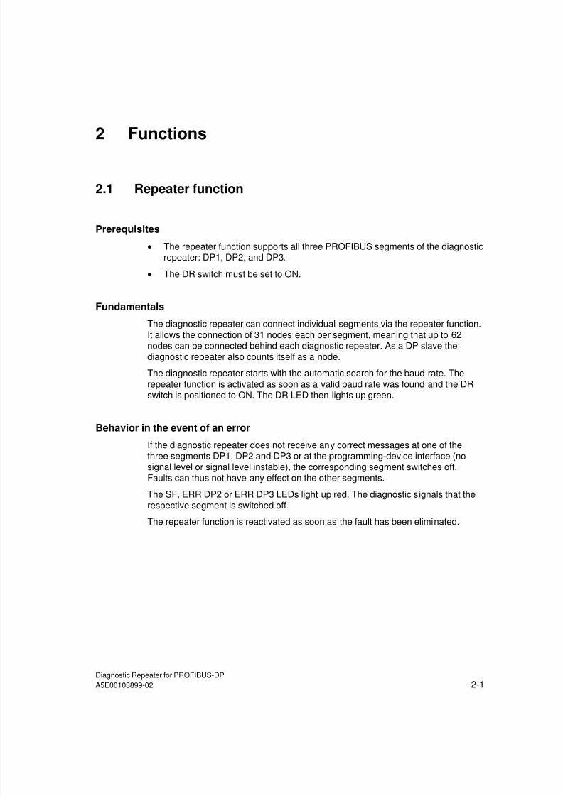
2.1 Repeater function
Prerequisites
• The repeater function supports all three PROFIBUS segments of the diagnosticrepeater: DP1, DP2, and DP3.
•
The DR switch must be set to ON.
Fundamentals
The diagnostic repeater can connect individual segments via the repeater function.It allows the connection of 31 nodes each per segment, meaning that up to 62nodes can be connected behind each diagnostic repeater. As a DP slave thediagnostic repeater also counts itself as a node.
The diagnostic repeater starts with the automatic search for the baud rate. Therepeater function is activated as soon as a valid baud rate was found and the DRswitch is positioned to ON. The DR LED then lights up green.
Behavior in the event of an error
If the diagnostic repeater does not receive any correct messages at one of thethree segments DP1, DP2 and DP3 or at the programming-device interface (nosignal level or signal level instable), the corresponding segment switches off.Faults can thus not have any effect on the other segments.
The SF, ERR DP2 or ERR DP3 LEDs light up red. The diagnostic signals that therespective segment is switched off.
The repeater function is reactivated as soon as the fault has been eliminated.
7/31/2019 Diagnose Repeater e
http://slidepdf.com/reader/full/diagnose-repeater-e 24/204
Functions
Diagnostic Repeater for PROFIBUS-DP2-2 A5E00103899-02
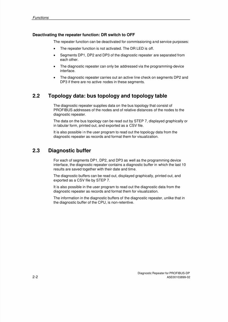
Deactivating the repeater function: DR switch to OFF
The repeater function can be deactivated for commissioning and service purposes:
• The repeater function is not activated. The DR LED is off.
•
Segments DP1, DP2 and DP3 of the diagnostic repeater are separated fromeach other.
• The diagnostic repeater can only be addressed via the programming-deviceinterface.
• The diagnostic repeater carries out an active line check on segments DP2 andDP3 if there are no active nodes in these segments.
2.2 Topology data: bus topology and topology table
The diagnostic repeater supplies data on the bus topology that consist ofPROFIBUS addresses of the nodes and of relative distances of the nodes to thediagnostic repeater.
The data on the bus topology can be read out by STEP 7, displayed graphically orin tabular form, printed out, and exported as a CSV file.
It is also possible in the user program to read out the topology data from thediagnostic repeater as records and format them for visualization.
2.3 Diagnostic buffer
For each of segments DP1, DP2, and DP3 as well as the programming deviceinterface, the diagnostic repeater contains a diagnostic buffer in which the last 10
results are saved together with their date and time.The diagnostic buffers can be read out, displayed graphically, printed out, andexported as a CSV file by STEP 7.
It is also possible in the user program to read out the diagnostic data from thediagnostic repeater as records and format them for visualization.
The information in the diagnostic buffers of the diagnostic repeater, unlike that inthe diagnostic buffer of the CPU, is non-retentive.

7/31/2019 Diagnose Repeater e
http://slidepdf.com/reader/full/diagnose-repeater-e 25/204
Functions
Diagnostic Repeater for PROFIBUS-DPA5E00103899-02 2-3
2.4 Statistics buffer
For segments DP2 and DP3 the diagnostic repeater contains two statistics buffersin which information on the reflection error rate and message frame error rate issaved together with the date and time. The statistics buffers allow conclusions tobe drawn about the quality of the bus system.
Reflection errors occur, for example, when the signal is reflected by a disturbed ordefective line.
Message frame errors are detected, for example, when message frames with parityerrors occur. Parity errors can be caused by a defective node, for example.
The statistics buffers can be read out, displayed graphically, printed out, andexported as a CSV file by STEP 7.
It is also possible in the user program to read out the statistics buffers from thediagnostic repeater as records and format them for visualization.
2.5 Time
The diagnostic repeater with the order number 6ES7 972-0AB01-0XA0 maintains aclock in order to time-stamp diagnostic events, statistical data, and topology data.
The time format corresponds to the S7 format "DATE_AND_TIME".
The time after power on is DT#1994-01-01-00:00:00:000.
The maximum possible end time is DT#2089-12-31-23:59:59.999.
2.5.1 Setting the time
To set the time in the diagnostic repeaters, read out the time from the CPU in theuser program with SFC 1 "READ_CLK", and write this time "cyclically" to thediagnostic repeaters on the selected DP master system using SFC 58 "WR_REC"or SFB 53 "WRREC".
The time can also be read out from the diagnostic repeater using SFC 59"RD_REC" or SFB 52 "RDREC" via the "Time" record.
The time reference should be set at regular intervals in order to ensure accuracy.

7/31/2019 Diagnose Repeater e
http://slidepdf.com/reader/full/diagnose-repeater-e 26/204
Functions
Diagnostic Repeater for PROFIBUS-DP2-4 A5E00103899-02
2.5.2 Time record format
Record 60 "Time" can be read and written. It consists of the version number andthe S7 data format DATE_AND_TIME:
Byte "Time" record Format
Bits 4-7 Bits 0-3
0 Constant 02 hex
1 Year Year BCD
2 Month Month BCD
3 Day Day BCD
4 Hour Hour BCD
5 Minute Minute BCD
6 Second Second BCD
7 Millisecond (high) Millisecond BCD
8 Millisecond (low) Day of the week:1 = Sunday2 = Monday3 = Tuesday4 = Wednesday5 = Thursday6 = Friday7 = Saturday
BCD
Note
Assign a time to all the diagnostic repeaters with the order number 6ES7 972-0AB01-0XA0 in the network.
Note
The diagnostic repeater does not have any power failure buffering. After poweroff/on, the clock starts again at DT#1994-01-01-00:00:00:000.
User program example
STL Description
CALL "READ_CLK" SFC1 Read out the time from the CPU
RET_VAL :=MW100 Error handling
CDT :=#datum_zeit Time, variable in the format DATE_AND_TIME
CALL "WR_REC" SFC58 Write record
REQ :=M1.0 Write time to the DR
IOID :=B#16#54 ID of the address range
LADDR :=W#16#3FE Diagnostic address of the DR
RECNUM :=B#16#3C Record number 60dec
RECORD :=#datum_zeit Time
RET_VAL :=MW102 Error output
BUSY :=M104.0 Job is being processed

7/31/2019 Diagnose Repeater e
http://slidepdf.com/reader/full/diagnose-repeater-e 27/204
Functions
Diagnostic Repeater for PROFIBUS-DPA5E00103899-02 2-5
2.6 Identification data
The identification data contain information on the diagnostic repeater and can beread with STEP 7 and partially written. The identification data are saved retentivelyin the diagnostic repeater.
Identification data Value range Default
Device
Manufacturer Read SIEMENS AG
Device designation Read Order number
Device serial number Read Dependent on version
Hardware revision Read
Software revision Read
Installation date Read/write
(max. 16 characters)
-
Static revision no. Read
Operating unit
TAG Read/write(max. 32 characters)
-
Description Read/write(max. 54 characters)
-
Explanations
Identification data DescriptionManufacturer The name of the manufacturer is stored here.
Device designation This is the order number of the diagnostic repeater.
Device serial number The serial number of the diagnostic repeater is stored here. Thispermits it to be identified uniquely.
Hardware revision Provides information on the version of the diagnostic repeater. Isincremented when the version and/or firmware of the diagnosticrepeater changes.
Software revision Provides information on the firmware version of the diagnosticrepeater. When the firmware version is incremented, thehardware version of the diagnostic repeater is also incremented.
Static revision no. Provides information on the parameterized changes on the
diagnostic repeater. The static revision number is incrementedafter every change.
Installation date Contains the date on which the diagnostic repeater wasinstalled. Enter the date here. Format: DD.MM.YYYY
TAG LID (location) of the diagnostic repeater. Enter a unique ID forthe diagnostic repeater here.
Description Freely definable text that is saved in the diagnostic repeater.You can enter additional information on the features of thediagnostic repeater here.
7/31/2019 Diagnose Repeater e
http://slidepdf.com/reader/full/diagnose-repeater-e 28/204
Functions
Diagnostic Repeater for PROFIBUS-DP2-6 A5E00103899-02
2.7 Monitoring functions for the clocked PROFIBUS bussystem
Features of the clocked PROFIBUS bus system
Reproducible response times (e.g. of the same length) are achieved in SIMATICwith an equidistant DP bus cycle and the synchronization of the following free-running individual cycles:
• Free-running cycle of the user program. The length of the cycle time can varyon the basis of acyclic program branching.
• Free-running, variable DP cycle on the PROFIBUS subnet
• Free-running cycle on the DP slave backplane bus.
• Free-running cycle at signal conditioning and conversion in the electronicmodules of the DP slaves.
All the affected cycles run with equidistance and clock synchronization. Theprocess response times thus have the same length and are shorter because of thelack of cycle jumps.
Monitoring functions of the diagnostic repeater
The diagnostic repeater offers functions for detecting errors in an equidistance DPbus cycle and reporting them to the associated DP master.
The following errors are detected:
• Violation of the equidistant DP cycle (TDP)
• Violation of the time TDX (cyclic part of the equidistant DP cycle)TDX monitoring establishes whether or not the I/O data have been received withthe "expected" time in relation to the beginning of the current cycle.
The violation of the time TDX can only be detected if the diagnostic repeater ishandled as the last node in the cyclic part of the equidistant DP cycle of the DPmaster.
You achieve this by:
• Assigning the diagnostic repeater the highest node address in the DP mastersystem and
• Using a DP master system in which the nodes are always processed in the
same order.To find out whether the DP master system used does this, refer to thecorresponding technical specifications.

7/31/2019 Diagnose Repeater e
http://slidepdf.com/reader/full/diagnose-repeater-e 29/204
Functions
Diagnostic Repeater for PROFIBUS-DPA5E00103899-02 2-7
Monitoring function data
The diagnostic repeater can monitor an equidistant DP bus cycle (TDP) from 1 msto 32 ms.
The diagnostic repeater is synchronized with the current, equidistant DP bus cycle
after 150 cycles. Diagnostic messages about equidistance violations are thusavoided in the startup phase.
The diagnostic repeater monitors the set or determined equidistant DP bus cyclewith a tolerance range of ±2 µs and the time TDX with a tolerance range of ±10 µs.
Prerequisites
• As of STEP 7 V5.1 with Service Pack 3
• The equidistance master must be a DP master class 1 (i.e. a programmingdevice/PC cannot be an equidistance master).
•
In equidistance mode only one DP master (class 1) can be active on thePROFIBUS-DP. Programming devices/PCs (class 2) can be connectedadditionally.

7/31/2019 Diagnose Repeater e
http://slidepdf.com/reader/full/diagnose-repeater-e 30/204
Functions
Diagnostic Repeater for PROFIBUS-DP2-8 A5E00103899-02

7/31/2019 Diagnose Repeater e
http://slidepdf.com/reader/full/diagnose-repeater-e 31/204
Diagnostic Repeater for PROFIBUS-DPA5E00103899-02 3-1
3 Configuration Options
3.1 Design guidelines for diagnostic repeaters
3.1.1 PROFIBUS networks
Design guidelines for PROFIBUS networks
When designing a PROFIBUS network with diagnostic repeaters the designguidelines and the information given in the manual SIMATIC NET PROFIBUS Networks (Order No. 6GK1970-5CA20-0AA1) apply.
MPI networks
Line diagnostics are not possible in pure MPI networks.
Mixed copper and fiber-optic cable networks
If it is possible to do without the full functionality (diagnostic functionality) of the
diagnostic repeater, diagnostic repeaters can be used in mixed copper and fiber-optic cable networks.
PROFIBUS FDL/FMS networks
Line diagnostics are in principle possible in PROFIBUS FDL/FMS networks. Undersome circumstances, however, nodes may not be detected or they may besubjected to interference during topology determination. Topology determinationshould therefore not be carried out in PROFIBUS FDL/FMS networks. Thediagnostic repeater used must not contain any topology data.
Diagnostic information can only be displayed through direct access to thediagnostic repeater from STEP 7 or COM PROFIBUS.

7/31/2019 Diagnose Repeater e
http://slidepdf.com/reader/full/diagnose-repeater-e 32/204
Configuration Options
Diagnostic Repeater for PROFIBUS-DP3-2 A5E00103899-02
3.1.2 PROFIBUS components
RS 485 bus terminal
The RS 485 bus terminal must not be used together with the diagnostic repeater.
Lightning protection elements
The diagnostic repeater can be used with the lightning protection elementsapproved for the PROFIBUS-DP.
Isolating transformer
The diagnostic repeater may only be used at the non-intrinsically-safe end of anisolating terminator.
The same limitations apply to the isolating terminator as for components withrepeater function.
ET 200U
The ET 200U module is not detected during topology determination. Inother words, it is not displayed in diagnostic messages in STEP 7 or COMPROFIBUS and is shown in the topology display as a node that cannot beassigned. Nevertheless, line diagnostics are still possible on the correspondingsegment without restrictions.
7/31/2019 Diagnose Repeater e
http://slidepdf.com/reader/full/diagnose-repeater-e 33/204
Configuration Options
Diagnostic Repeater for PROFIBUS-DPA5E00103899-02 3-3
3.1.3 Bus connectors and cables
PROFIBUS-DP bus connectors
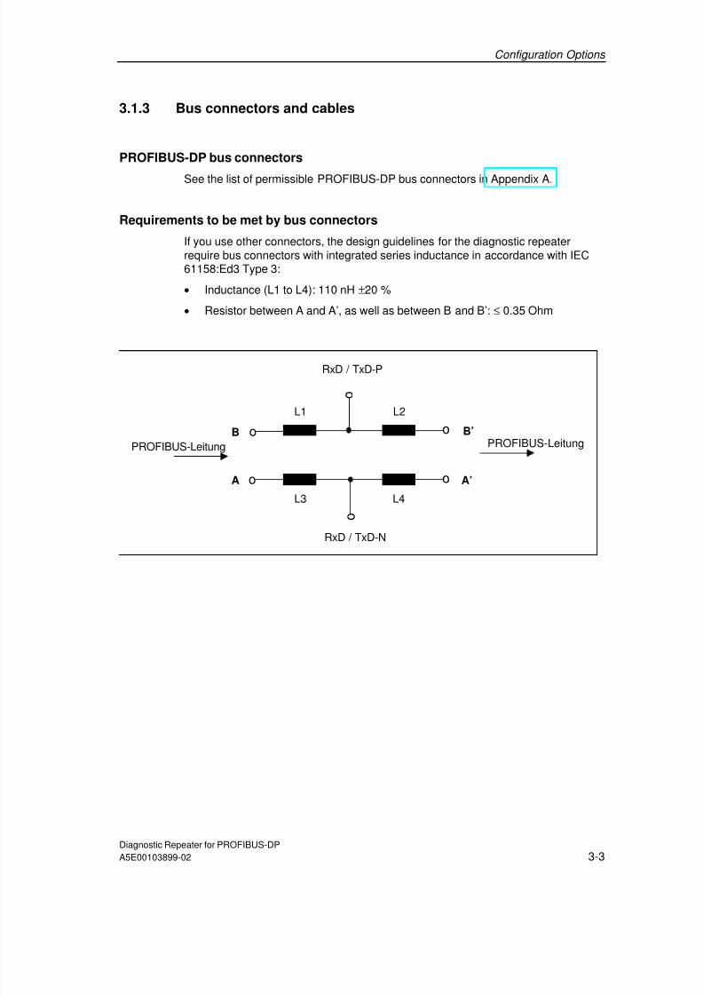
See the list of permissible PROFIBUS-DP bus connectors in Appendix A.
Requirements to be met by bus connectors
If you use other connectors, the design guidelines for the diagnostic repeaterrequire bus connectors with integrated series inductance in accordance with IEC61158:Ed3 Type 3:
• Inductance (L1 to L4): 110 nH ±20 %
• Resistor between A and A’, as well as between B and B’: ≤ 0.35 Ohm
RxD / TxD-N
RxD / TxD-P
L3
L2L1
L4
o
o
o
o
o
o
PROFIBUS-Leitung
A A’
B B’PROFIBUS-Leitung

7/31/2019 Diagnose Repeater e
http://slidepdf.com/reader/full/diagnose-repeater-e 34/204
Configuration Options
Diagnostic Repeater for PROFIBUS-DP3-4 A5E00103899-02
SIMATIC NET PROFIBUS cables
See Appendix A for a list of permissible SIMATIC NET PROFIBUS cables.
Requirements to be met by cables
Note
If you are using cables that are not designed for the Fast Connect connectionsystem, you will have to convert to FastConnect cables.
If you are using other cables, the design guidelines for the diagnostic repeaterrequire them to comply with the technical specifications in the table below:
Technical specifications Values
Attenuation
At 16 MHz
At 4 MHz
At 38.4 kHz
At 9.6 kHz
< 42 dB/km
< 22 dB/km
< 4 dB/km
< 2.5 dB/km
Characteristic impedance
At 3 to 20 MHz
At 38.4 kHz
At 9.6 kHz
150 ± 15 Ω
185 ± 18.5 Ω
270 ± 27 Ω
Rated value 150 Ω
Loop resistance ≤ 110 Ω /km Shield resistance ≤ 9.5 Ω /km
Working capacity Approx. 28.5 nF/km
If you are using a cable that does not comply with the specifications in the table,get in touch with your SIEMENS contact.
7/31/2019 Diagnose Repeater e
http://slidepdf.com/reader/full/diagnose-repeater-e 35/204
Configuration Options
Diagnostic Repeater for PROFIBUS-DPA5E00103899-02 3-5
3.1.4 Line length and cascading depth
Maximum monitorable line length
If you are using standard cables, at baud rates of 9.6 kbps to 12 Mbps thediagnostic repeater can monitor a maximum of 100 m of cable per segment (DP2,DP3).
The monitorable line length of some cable types is limited (see Appendix A).
Cascading depth
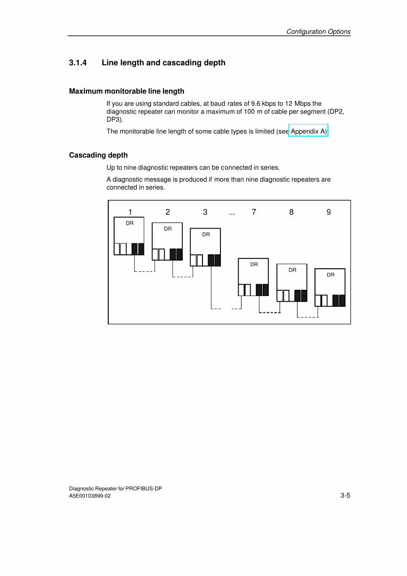
Up to nine diagnostic repeaters can be connected in series.
A diagnostic message is produced if more than nine diagnostic repeaters areconnected in series.
DRDR
DR
DRDR
DR
1 2 3 7 8 9...
7/31/2019 Diagnose Repeater e
http://slidepdf.com/reader/full/diagnose-repeater-e 36/204
Configuration Options
Diagnostic Repeater for PROFIBUS-DP3-6 A5E00103899-02
3.1.5 Spur lines
Spur lines, including those within devices, are not permissible. The party line of theS7-300 corresponds, for example, to an internal device spur line with a length of upto 0.6 m.
Caution
Spur lines are not allowed at segments DP2 and DP3 of diagnostic repeaters sincethey prevent correct determination of the topology and fault points.
Avoiding spur lines
Spur lines arise, for example, when programming devices or nodes are connectedas a branching or when PROFIBUS if connectors are stacked over each other.Methods of avoiding spur lines:
• Connect the programming devices directly to the programming device interfaceof the diagnostic repeater or
• To connect programming devices, use only the SIMATIC S5/S7 spur line for 12Mbps ("active cable").
• The RS 485 bus terminal may not be used.
Arrangement of the nodes without spur lines
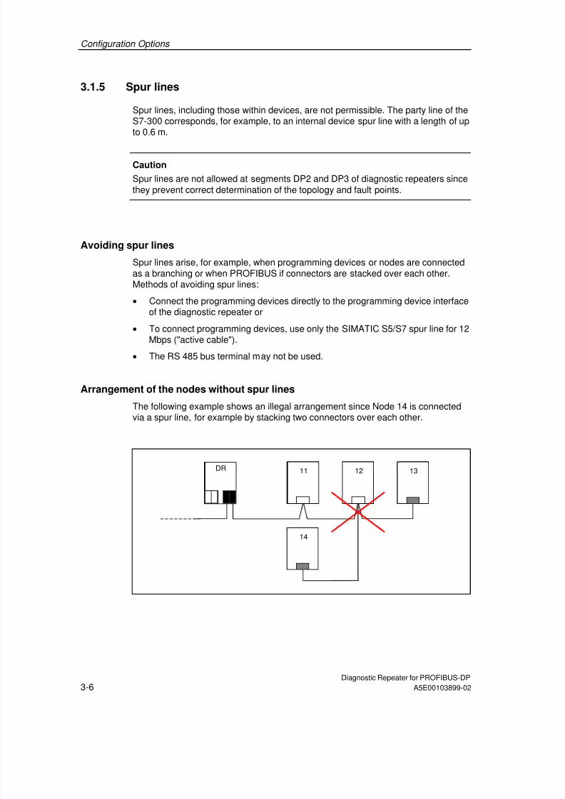
The following example shows an illegal arrangement since Node 14 is connected
via a spur line, for example by stacking two connectors over each other.
xDR 1311 12
14

7/31/2019 Diagnose Repeater e
http://slidepdf.com/reader/full/diagnose-repeater-e 37/204
7/31/2019 Diagnose Repeater e
http://slidepdf.com/reader/full/diagnose-repeater-e 38/204
Configuration Options
Diagnostic Repeater for PROFIBUS-DP3-8 A5E00103899-02
3.1.7 Arrangement of the DP master
Prerequisite for topology determination
For topology determination, a DP master is required that initiates the requiredmeasurements and that can be used by the diagnostic repeater to make itsdiagnostic information available.
Arrangement of the DP master
It is advisable to connect the DP master to the connections A1/B1 of segment DP1of a diagnostic repeater.
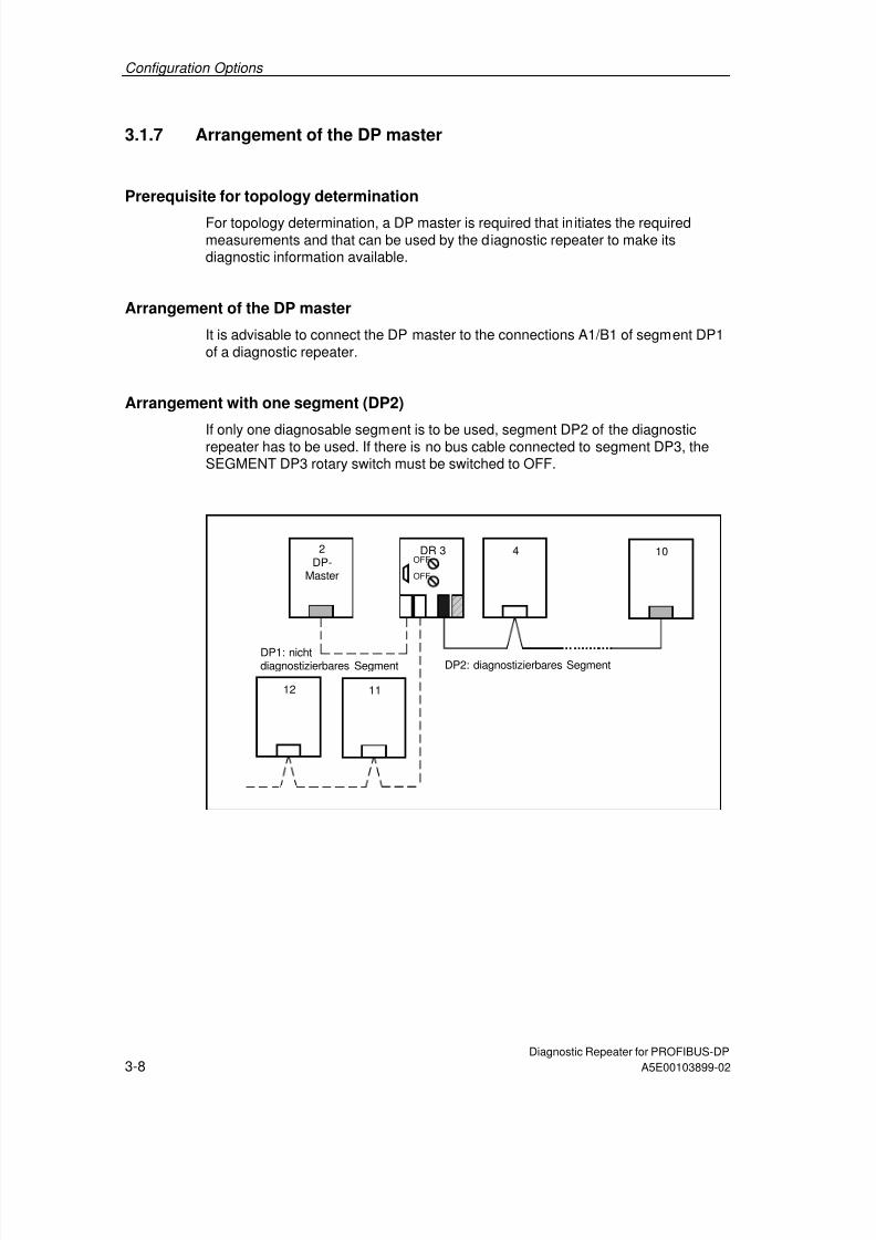
Arrangement with one segment (DP2)
If only one diagnosable segment is to be used, segment DP2 of the diagnosticrepeater has to be used. If there is no bus cable connected to segment DP3, theSEGMENT DP3 rotary switch must be switched to OFF.
4 10
12 11
2
DP-Master
DR 3
OFF
OFF
DP1: nichtdiagnostizierbares Segment DP2: diagnostizierbares Segment
7/31/2019 Diagnose Repeater e
http://slidepdf.com/reader/full/diagnose-repeater-e 39/204

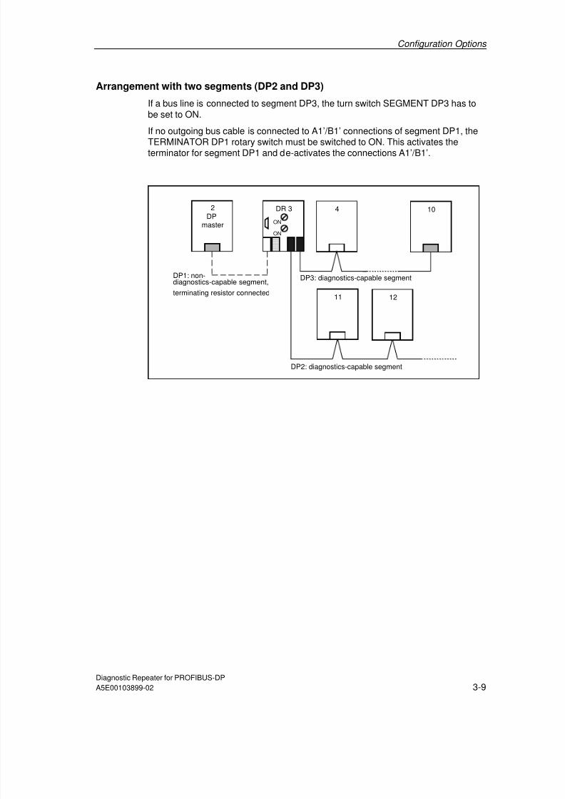
7/31/2019 Diagnose Repeater e
http://slidepdf.com/reader/full/diagnose-repeater-e 40/204
Configuration Options
Diagnostic Repeater for PROFIBUS-DP3-10 A5E00103899-02
3.1.8 Example configuration
Example configuration
2DP
master
3
7
25
5
31
32 33
41 43
34
DR 4
OFFON
DR 12
ON
OFF
DR 40
ON
ON
DR 24
ON
ON
DR 22
OFFON
DR 6
ONON
PG 0
23
42

7/31/2019 Diagnose Repeater e
http://slidepdf.com/reader/full/diagnose-repeater-e 41/204
Configuration Options
Diagnostic Repeater for PROFIBUS-DPA5E00103899-02 3-11
Notes
Six diagnostic repeaters (DR) are used in the example. Of these four are switchedin series (DR 4, 6, 24 and 40). DP3 of the DR 12 is de-activated. At the diagnosticrepeaters DR 6, 12, 24 and 40 the terminators for segment DP1 are connected,
since no outgoing bus lines are connected to DP1.Segment DP1 of the DR 4 and the line to the programming device cannot bediagnosed. Line faults can be recognized and localized in all other segments.
Figure Description
PG Interface for PGwith integrated terminating resistor
SEGMENT DP3 Activate/deactivate segment DP3ON = activate segment DP3OFF = deactivate segment DP3
TERMINATOR DP1 Terminating resistor for segment DP1
ON = terminating resistor connectedOFF = terminating resistor not connected(if both connections to DP1 are used)
DP1 Connections for segment DP1
Connection A1’/B1’ of segment DP1 de-activated
DP2 Connections for segment DP2,with measuring circuit for line diagnostics
DP3 Connection for segment DP3,with measuring circuit for line diagnostics
SEGMENT DP3
DIAGNOSTIC REPEATER
DP3DP2DP1
TERMINATOR DP1
OFFON
OFFON
PG
Segment DP3 de-activated
Terminator at Node x not connectedx
Terminator connected
PG 0PG PG, terminator connected
P3

7/31/2019 Diagnose Repeater e
http://slidepdf.com/reader/full/diagnose-repeater-e 42/204
Configuration Options
Diagnostic Repeater for PROFIBUS-DP3-12 A5E00103899-02
3.2 Limitations when using components with repeaterfunction
Note
Components with repeater function can be used if partially faulty determination ofthe topology is acceptable and if it is possible to do without line diagnostics afterthe component with repeater function.
Rule
Components with a repeater function can be used:
• Without limitations in segment DP1 and at the end of segments DP2 and DP3of a diagnostic repeater
• In segments DP2 and DP3, when topology determination with some errors isacceptable and it is possible to do without line diagnostics in the correspondingsegment after the component with a repeater function.
PROFIBUS components with a repeater function
The following PROFIBUS components can be used, for example, in connectionwith the diagnostic repeater:
• RS 485 repeater
• Optical Link Module (OLM),
• Optical Bus Terminal (OBT),
• Infrared Link Module (ILM),
• Power Rail Booster,
• Data photoelectric barriers via PROFIBUS-DP.

7/31/2019 Diagnose Repeater e
http://slidepdf.com/reader/full/diagnose-repeater-e 43/204
Configuration Options
Diagnostic Repeater for PROFIBUS-DPA5E00103899-02 3-13
Explanation
The line diagnostic only functions up to the component with repeater function.Every downstream node is indicated with the distance of the component withrepeater function.
Consequences:
• The nodes are entered with incorrect specification of the distance in thetopology table.
• The relative specification of the error can possibly not be indicated correctly.
• All the nodes lying before and after the component with repeater function arecounted as nodes of one PROFIBUS-DP segment. This can lead to the errormessage "More than 32 nodes connected to a measuring segment". This errormessage can be suppressed by de-activating the determination of the topologyfor this segment in the configuration of the diagnostic repeater.
Components with integrated section monitoring
Caution
Components with integrated section monitoring, such as the Optical Link Module(OLM), can lead to segments being broken and thus to bus faults and interruptionswhile the topology is being determined.
Deactivate the determination of the topology for that segment of the diagnosticrepeater to which components with integrated section monitoring are connected(see Section 6.3.2).

7/31/2019 Diagnose Repeater e
http://slidepdf.com/reader/full/diagnose-repeater-e 44/204
Configuration Options
Diagnostic Repeater for PROFIBUS-DP3-14 A5E00103899-02
Network design with component with repeater function
The following example shows a possible network design with a component withrepeater function (R).
DR 4
OFF
OFF5
R
76 8
5 m
12 m
25 m
20 m
30 m
PROFIBUS segment:max. 32 nodes PROFIBUS segment: max. 32 nodes
The component with a repeater function is not detected as a node (no PROFIBUSaddress of its own) and is thus not listed in the topology table.
The diagnostic repeater 4 determines the following data for segment DP2:
PROFIBUS address Distance from
diagnostic repeater 4
Topology determination
5 5 m Correct
6 12 m ! Faulty
7 12 m ! Faulty
8 12 m ! Faulty

7/31/2019 Diagnose Repeater e
http://slidepdf.com/reader/full/diagnose-repeater-e 45/204
Configuration Options
Diagnostic Repeater for PROFIBUS-DPA5E00103899-02 3-15
3.2.1 Network design with an RS 485 repeater
Possible network design
DR 4
OFF
OFF
5 6 7 8
1210 11
F1
F2
F3
7 m
14 m
18 m
30 m
30 m
20 m
16 15 14
40 m
?
?
?
?
25 m
DR 13
ON
ONRS485
7/31/2019 Diagnose Repeater e
http://slidepdf.com/reader/full/diagnose-repeater-e 46/204
Configuration Options
Diagnostic Repeater for PROFIBUS-DP3-16 A5E00103899-02
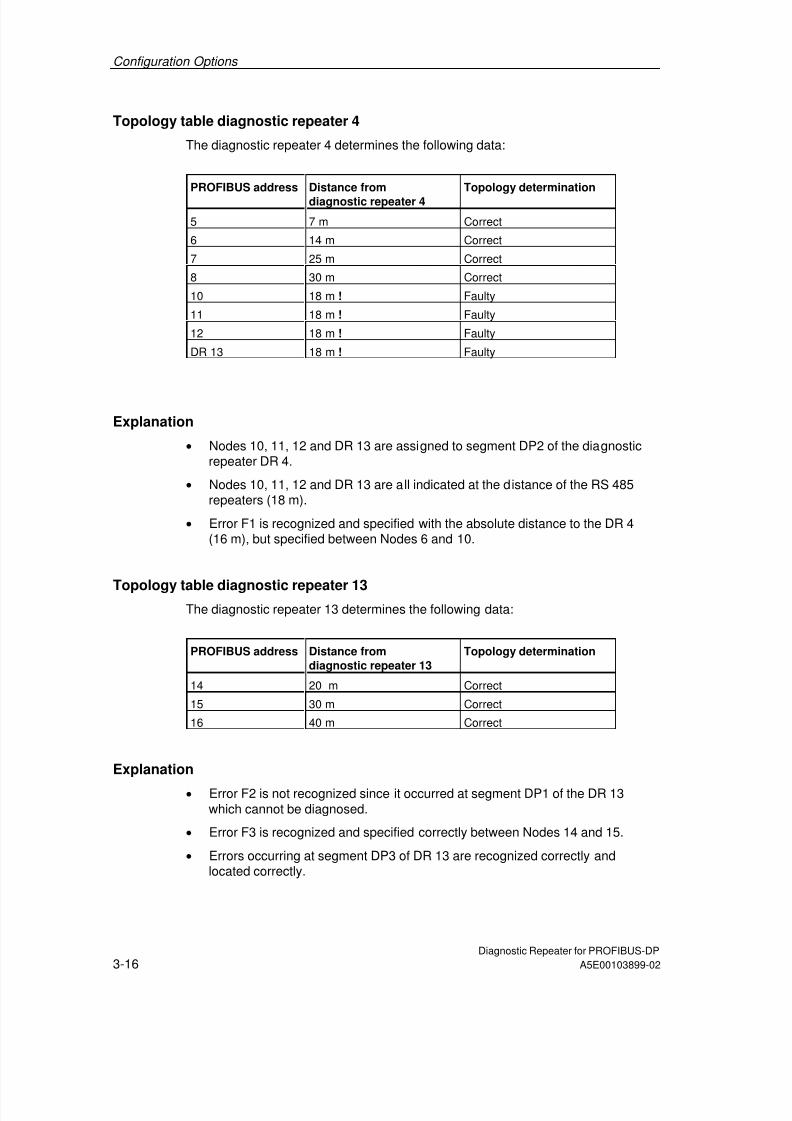
Topology table diagnostic repeater 4
The diagnostic repeater 4 determines the following data:
PROFIBUS address Distance fromdiagnostic repeater 4
Topology determination
5 7 m Correct
6 14 m Correct
7 25 m Correct
8 30 m Correct
10 18 m ! Faulty
11 18 m ! Faulty
12 18 m ! Faulty
DR 13 18 m ! Faulty
Explanation
• Nodes 10, 11, 12 and DR 13 are assigned to segment DP2 of the diagnosticrepeater DR 4.
• Nodes 10, 11, 12 and DR 13 are all indicated at the distance of the RS 485repeaters (18 m).
• Error F1 is recognized and specified with the absolute distance to the DR 4(16 m), but specified between Nodes 6 and 10.
Topology table diagnostic repeater 13The diagnostic repeater 13 determines the following data:
PROFIBUS address Distance fromdiagnostic repeater 13
Topology determination
14 20 m Correct
15 30 m Correct
16 40 m Correct
Explanation
• Error F2 is not recognized since it occurred at segment DP1 of the DR 13which cannot be diagnosed.
• Error F3 is recognized and specified correctly between Nodes 14 and 15.
• Errors occurring at segment DP3 of DR 13 are recognized correctly andlocated correctly.

7/31/2019 Diagnose Repeater e
http://slidepdf.com/reader/full/diagnose-repeater-e 47/204
Configuration Options
Diagnostic Repeater for PROFIBUS-DPA5E00103899-02 3-17
3.2.2 Network design with an Optical Link Module (OLM)
Possible network design
If you use an Optical Link Module (OLM) with integrated section monitoring in yourplant, you must de-activate the determination of the topology for segment (DP2) ofthe diagnostic repeater (DR 4) to which the module is connected.
DR 4
OFF
OFF5 6 7 8
7 m
14 m18 m
30 m
25 m
OLM
OLM
11
F3
30 m
20 m
15 14 13
40 m
DR 12
ON
ON
F2
F1

7/31/2019 Diagnose Repeater e
http://slidepdf.com/reader/full/diagnose-repeater-e 48/204
Configuration Options
Diagnostic Repeater for PROFIBUS-DP3-18 A5E00103899-02
Topology table diagnostic repeater 4
The topology determination function of the diagnostic repeater 4 has to be de-activated for segment DP2 by means of the configuration (see Section 6.3.2). Nodata are determined.
Caution
Components with integrated section monitoring, such as the Optical Link Module(OLM), can lead to segments being broken and thus to bus faults and interruptionswhile the topology is being determined.
Explanation
• The topology cannot be determined for segment DP2 due to the connectedOptical Link Module.
• Nodes 11 and DR 12 are assigned to segment DP2 of the diagnostic repeaterDR 4.
• Error F1 is recognized and specified with the absolute distance to thediagnostic repeater DR 4 (16 m).
Topology table diagnostic repeater 12
The diagnostic repeater 12 determines the following data for segment DP2:
PROFIBUS address Distance fromdiagnostic repeater 12
Topology determination
13 20 m Correct14 30 m Correct
15 40 m Correct
Explanation
• The topology can be determined correctly for segments DP2 and DP3.
• Error F2 is not recognized since it occurred at segment DP1 of the DR 12which cannot be diagnosed.
• Error F3 is recognized and specified correctly between Nodes 13 and 14.
• Errors occurring at segment DP3 of DR 12 are recognized correctly andlocated correctly.

7/31/2019 Diagnose Repeater e
http://slidepdf.com/reader/full/diagnose-repeater-e 49/204
Configuration Options
Diagnostic Repeater for PROFIBUS-DPA5E00103899-02 3-19
3.3 Recommendations for structuring a new plant
Multiple-stage diagnostic concept
A multiple-stage diagnostic concept allows monitoring of a PROFIBUS networkduring every plant phase. It provides for the following procedure for structuring andoperating a new plant:
• Installation: avoiding errors in the physical structure of the bus by using theFast Connect system
• Installation/commissioning: checking the physical structure of the bus withthe BT 200 test device in offline mode
• Current operation: line diagnostics through the use of the diagnostic repeater
Fast Connect system
PROFIBUS Fast Connect is a system for preparing copper PROFIBUS cablesquickly and easily.
The system consists of three components suited to each other:
• Fast Connect bus lines for rapid mounting,
• Fast Connect Stripping Tool,
• Fast Connect bus connector for PROFIBUS (with insulation piercing).
PROFIBUS test device BT 200
During the installation phase the test device BT 200 can be used to check thePROFIBUS line even when the nodes are plugged. Installation errors are foundand logged rapidly. The person installing does not require any special PROFIBUSknowledge.
The test device BT 200 can check the following points:
• Wire break, shield break, missing or too many terminators,
• Short circuit (A to B, A/B to shield),
• Reflection points which cause faults,
• Interchanged signal lines A/B,
• Specification of the length of the laid line,
• Availability of the slaves,
• PROFIBUS interface of the nodes.

7/31/2019 Diagnose Repeater e
http://slidepdf.com/reader/full/diagnose-repeater-e 50/204
Configuration Options
Diagnostic Repeater for PROFIBUS-DP3-20 A5E00103899-02
3.4 Use in an existing plant
Points to be observed when extending an existing plant
If you want to add diagnostic repeaters to an existing plant, you must:
• Observe the design guidelines for the diagnostic repeater,
• Use a programming device/PC with STEP 7 or COM PROFIBUS or an S7 CPUwith the integrated system function SFC 103 "DP_TOPOL", in order to be ableto carry out topology determination,
• Re-configure the DP master used in order to include the diagnostic repeater asa new DP slave and in order to be able to access the diagnostic information ofthe diagnostic repeater.
Points to be observed when replacing a diagnostic repeater
You only receive correct diagnostic messages and distance specifications if youdetermine the topology after replacing a diagnostic repeater. Otherwise theinformation provided will be incorrect or incomplete.
Using a brand-new diagnostic repeater
The topology table of a brand-new diagnostic repeater is empty at first. In otherwords, the diagnostic repeater can only supply the distance of a fault location inabsolute terms (e.g. the fault location is 30 meters from the diagnostic repeater).
Using a diagnostic repeater that has already been used
The topology table of a diagnostic repeater that has already been used contains
information on the plant from which it has been taken.This means that the diagnostic repeater can specify the distance to a fault pointabsolutely and relatively. However, as a rule this information is not suitable for thenew plant.
Changes to plants
The topology must always be determined when a plant is changed, meaning whenyou
• Add nodes,
• Exchange nodes,
• Remove nodes,
• Change PROFIBUS addresses,
• Change the line length.

7/31/2019 Diagnose Repeater e
http://slidepdf.com/reader/full/diagnose-repeater-e 51/204
Diagnostic Repeater for PROFIBUS-DPA5E00103899-02 4-1
4 Installation
4.1 Mounting rules
Mounting dimensions
Installation height: 125 mm
Installation width: 80 mm
Installation depth without rail: 66.3 mmInstallation depth with rail: 72.2 mm
Mounting position
Permissible mounting positions are horizontal and vertical mounting on a verticallevel.
Mounting rail
The diagnostic repeater can be mounted on the following mounting rails:
• Mounting rail for S7-300 or
• DIN rail conforming to EN 50022 (35 x 15 mm)
Required tool
Screw driver 4 mm
Prerequisites
The mounting rail is mounted.
7/31/2019 Diagnose Repeater e
http://slidepdf.com/reader/full/diagnose-repeater-e 52/204
Installation
Diagnostic Repeater for PROFIBUS-DP4-2 A5E00103899-02
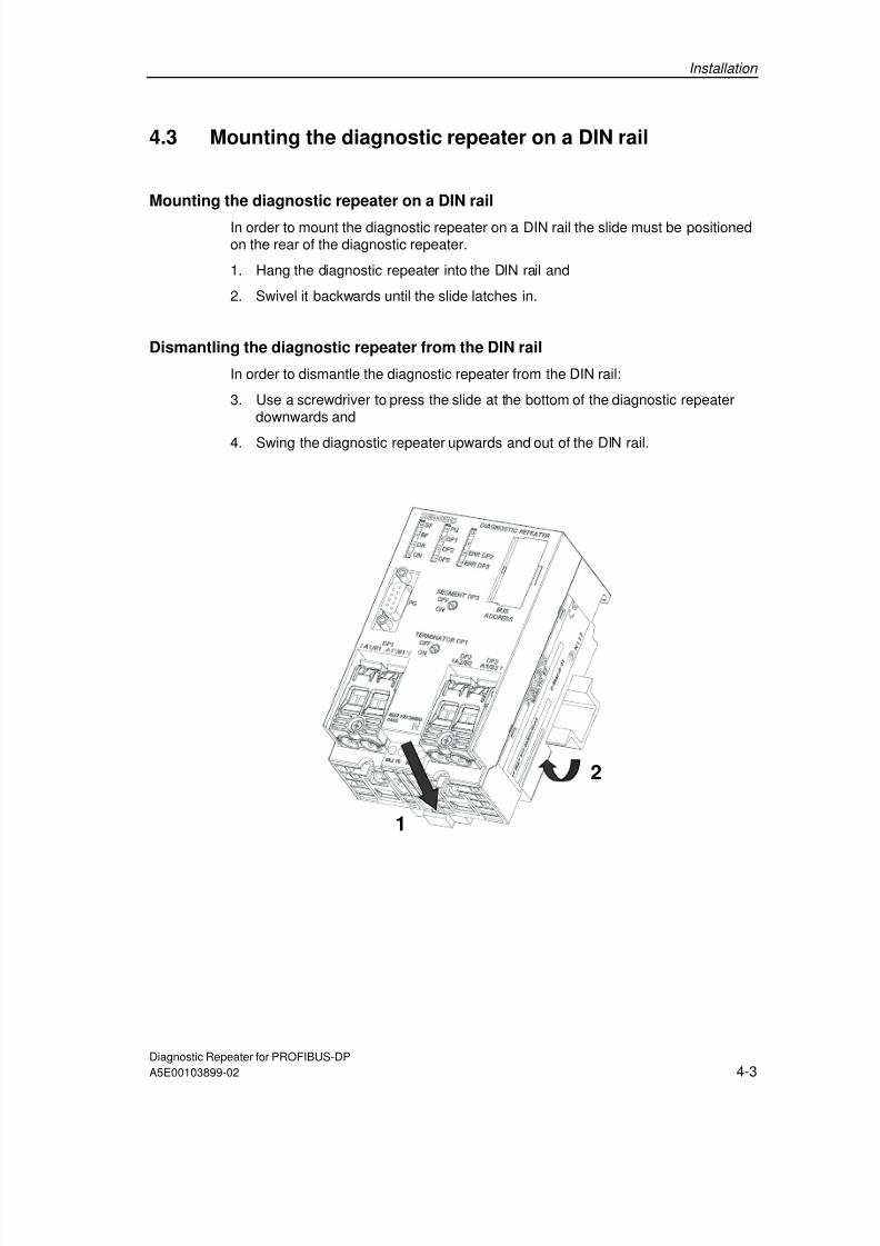
4.2 Mounting the diagnostic repeater on a mounting rail forS7-300
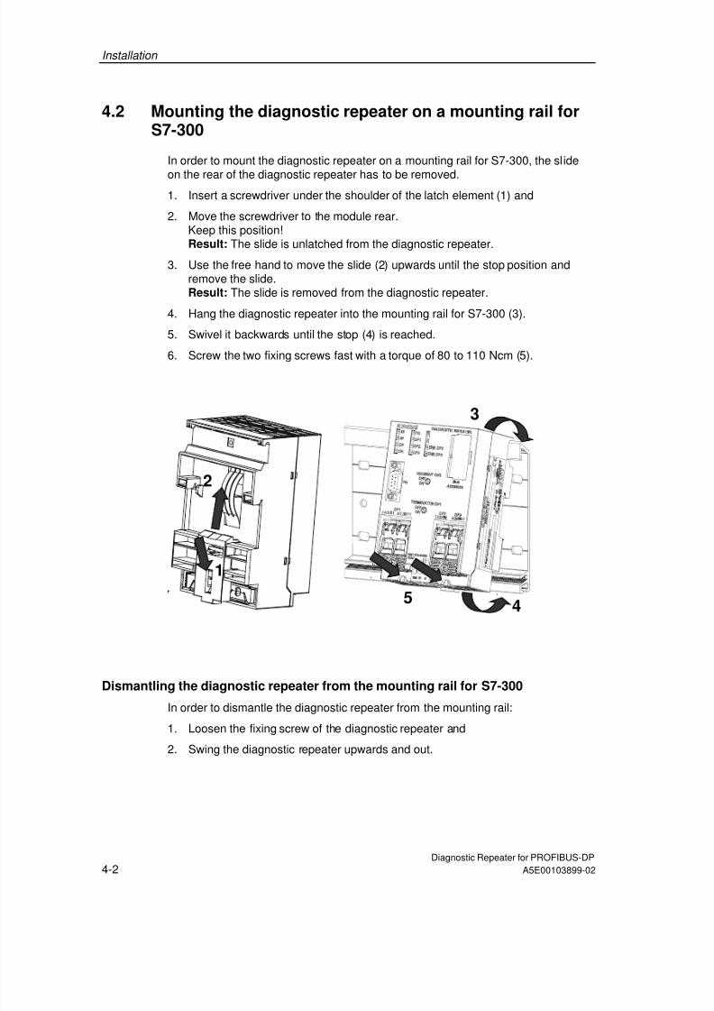
In order to mount the diagnostic repeater on a mounting rail for S7-300, the slide
on the rear of the diagnostic repeater has to be removed.1. Insert a screwdriver under the shoulder of the latch element (1) and
2. Move the screwdriver to the module rear.Keep this position!Result: The slide is unlatched from the diagnostic repeater.
3. Use the free hand to move the slide (2) upwards until the stop position andremove the slide.Result: The slide is removed from the diagnostic repeater.
4. Hang the diagnostic repeater into the mounting rail for S7-300 (3).
5. Swivel it backwards until the stop (4) is reached.
6. Screw the two fixing screws fast with a torque of 80 to 110 Ncm (5).
1
2
54
3
Dismantling the diagnostic repeater from the mounting rail for S7-300
In order to dismantle the diagnostic repeater from the mounting rail:1. Loosen the fixing screw of the diagnostic repeater and
2. Swing the diagnostic repeater upwards and out.
7/31/2019 Diagnose Repeater e
http://slidepdf.com/reader/full/diagnose-repeater-e 53/204

7/31/2019 Diagnose Repeater e
http://slidepdf.com/reader/full/diagnose-repeater-e 54/204
Installation
Diagnostic Repeater for PROFIBUS-DP4-4 A5E00103899-02

7/31/2019 Diagnose Repeater e
http://slidepdf.com/reader/full/diagnose-repeater-e 55/204
Diagnostic Repeater for PROFIBUS-DPA5E00103899-02 5-1
5 Wiring
5.1 Basis
Prerequisites
The diagnostic repeater is mounted on the mounting rail.
Particular points when wiring
All the lines are connected from below. The bus cables are connected by means ofan insulation piercing technique (Fast Connect connection system). The insulationpiercing connecting devices are designed for 10 connecting cycles.
Note
Insulation residues can remain in the insulation piercing connecting device duringopening.This can cause problems during the next connection process.Therefore ensure that no insulation residues remain when you withdraw the linewhile opening the insulation piercing connecting device.
Required tool
• Use, for example, the Fast Connect stripping tool (order no. 6GK1905-6AA00)
• Screw driver 4 mm.

7/31/2019 Diagnose Repeater e
http://slidepdf.com/reader/full/diagnose-repeater-e 56/204
Wiring
Diagnostic Repeater for PROFIBUS-DP5-2 A5E00103899-02
5.2 Connecting the supply voltage
Cable types
The following cables can be used to connect the 24 V DC supply cables:
• Rigid cable: 0.14 mm2 to 2.5 mm2
• Flexible cable with wire end ferrule: 0.25 mm2 to 1.5 mm2
• Flexible cable without wire end ferrule from 0.14 mm2 to 2.5 mm2
Connecting the power supply
Connect the power supply of the diagnostic repeater as follows:
1. Bare the cable for the 24 V DC supply voltage.
2. Connect the cable to the terminals "PE", "M" and "L+".
The terminal M5.2 of the power supply is the groundreference for external signal messages.This terminal may not be wired.

7/31/2019 Diagnose Repeater e
http://slidepdf.com/reader/full/diagnose-repeater-e 57/204
Wiring
Diagnostic Repeater for PROFIBUS-DPA5E00103899-02 5-3
5.3 Connecting the PROFIBUS cables
Prerequisites: bus connectors and cables
Note the requirements placed on the bus connectors and cables that you use inyour plant with the diagnostic repeater (see Section 3.1.3).
Overview of the procedure
• Connecting the PROFIBUS cables
• Connecting or disconnecting the terminator DP1
• Connecting or disconnecting segment DP3
Connecting the PROFIBUS cables
Connect the PROFIBUS cable to the diagnostic repeater as follows:
1. Cut the PROFIBUS cable to the required length.
2. Bare the PROFIBUS cable in accordance with the figure.
3. Screw open the black strain relief.
4. Open the transparent contacting cover for the insulation piercing connectingdevice.
5. Insert the incoming cable of segment DP1 into the contacting cover A1/B1, theoutgoing cable into the contacting cover A1’/B1’. Insert the outgoing cables ofsegments DP2 and DP3 into the contacting cover A2/B2 and A3/B3. Terminate
red to red and green to green.6. Press the contacting cover firmly downwards.
7. Screw the black strain relief closed.
Stripping
7,5+1
15+/-2FC stripping tool: 6GK1905-6AA00

7/31/2019 Diagnose Repeater e
http://slidepdf.com/reader/full/diagnose-repeater-e 58/204
Wiring
Diagnostic Repeater for PROFIBUS-DP5-4 A5E00103899-02
Connections
• Connection A1/B1 for the feeding bus line of segment DP1
• Connection A1/B1 for the outgoing bus line of segment DP1
• Connection A2/B2 for the bus cable of segment DP2• Connection A3/B3 for the bus cable of segment DP3
• Connections for the power supply
DP3
A3/B3
DP2
A2/B2DP1
A1/B1 A1´/B1´
Connecting/disconnecting TERMINATOR DP1
If no outgoing bus cable is connected to the connections A1’/B1’ of segment DP1,set the turn screw TERMINATOR DP1 to ON on the diagnostic repeater.
Connecting/disconnecting SEGMENT DP3
If no bus cable is connected to segment DP3, set the turn switch SEGMENT DP3
to OFF on the diagnostic repeater.

7/31/2019 Diagnose Repeater e
http://slidepdf.com/reader/full/diagnose-repeater-e 59/204
Wiring
Diagnostic Repeater for PROFIBUS-DPA5E00103899-02 5-5
5.4 Block diagram of the diagnostic repeater
Block diagram
Segment
DP2Segment
DP3
RS-485
Segment
DP1
Logic
L+
M
DC 24V
Electricalisolation
Electrical
isolation
M5.2
PE
Measuringcircuit
M5.2
P5.2
M5.1
P5.1
RS-485
R
ON
OFF
1 MOhm1 MOhm
10 MOhm
PG socket
A1/B1 A1’/B1’
Measuringcircuit
Power supply

7/31/2019 Diagnose Repeater e
http://slidepdf.com/reader/full/diagnose-repeater-e 60/204
Wiring
Diagnostic Repeater for PROFIBUS-DP5-6 A5E00103899-02
Control-to-load isolation
• Segment DP1 which cannot be diagnosed is isolated from segments DP2, DP3which can be diagnosed and from the programming-device interface
• The power supply is isolated.
• Segments DP2, DP3 and the programming-device interface are non-isolated toeach other.
Earth-free operation
Earth-free operation means that the ground and the PE are not connected to eachother.
Earth-free operation of the diagnostic repeater means that bus segments can beoperated isolated.
Designing a diagnostic repeater earth-free
In order to ensure earth-free operation of the diagnostic repeater you have toensure earth-free power supply of the diagnostic repeater.
The PE terminal must always be connected.
Programming device connection of the diagnostic repeater
The programming device connection is only available for one node (programmingdevice or OP) and is not designed for networking. The terminating resistor is firmlyintegrated in the programming device interface of the diagnostic repeater.
When using cables with bus connectors you should therefore switch theterminating resistor on the diagnostic repeater side to OFF and on theprogramming device/OP side, as usual, to ON.
Pin assignment of the cannon connector (PG socket)
View Pin No. Signal name Designation
1 - -
2 M24 V Ground 24 V
3 RxD/TxD-P Data line B
4 RTS Request to Send
5 M5V2 Data reference potential (from node)
6 P5V2 Supply plus (from node)
7 P24V 24 V
8 RxD/TxD-N Data line A
2
4
1
5
37
9
6
8
9 - -
7/31/2019 Diagnose Repeater e
http://slidepdf.com/reader/full/diagnose-repeater-e 61/204
Diagnostic Repeater for PROFIBUS-DPA5E00103899-02 6-1
6 Commissioning
6.1 Addressing
Prerequisites
The diagnostic repeater is designed as a DP slave and therefore has its ownPROFIBUS address. This specifies under which address the diagnostic repeater isaddressed at the PROFIBUS-DP.
• The PROFIBUS address is set by means of switches. They are positioned onthe front of the diagnostic repeater, protected by a hinged window.
• The PROFIBUS addresses 1 to 125 are permitted.
• Each address may only be assigned once at the PROFIBUS-DP.
Note
The LEDs SF, BF and DR flash if the illegal PROFIBUS addresses 0, 126 and 127are set.
Required Tool
Screw driver 4 mm

7/31/2019 Diagnose Repeater e
http://slidepdf.com/reader/full/diagnose-repeater-e 62/204
Commissioning
Diagnostic Repeater for PROFIBUS-DP6-2 A5E00103899-02
Setting a PROFIBUS address
The PROFIBUS address results from the addition of the numbers which areassigned to the switches.
1. Swivel open the window at the diagnostic repeater.
2. Use the switches to set the desired PROFIBUS address.
3. Close the window.
The switches are activated if they are pressed to the left.
The example has the PROFIBUS address:
64 + 16 + 8 + 2 = 90.
Changing the PROFIBUS address
You can change the set PROFIBUS address at any time. The diagnostic repeatertakes over the modified PROFIBUS address after the 24 V DC supply has beenswitched off and on.

7/31/2019 Diagnose Repeater e
http://slidepdf.com/reader/full/diagnose-repeater-e 63/204
Commissioning
Diagnostic Repeater for PROFIBUS-DPA5E00103899-02 6-3
6.2 Configuration
Prerequisites
The diagnostic repeater is configured with STEP 7 or COM PROFIBUS.
The diagnostic repeater is connected to the DP master system as a DP slave.
• STEP 7
As of STEP 7 V5.1 with Service Pack 2, the diagnostic repeater appears in thehardware catalog of STEP 7 under PROFIBUS-DP / Network Components / Diagnostic Repeaters.In older versions of STEP 7, the diagnostic repeater is integrated via the DDB file.In this case, it appears in the hardware catalog under PROFIBUS-DP / AdditionalField Devices / General.
• COM PROFIBUS
As of COM PROFIBUS V5.1 with Service Pack 2, the repeater appears underDP slave / General / Network Components / Diagnostic Repeaters.In older versions of COM PROFIBUS, the diagnostic repeater is integrated via theDDB file.
Available functions with STEP 7
Diagnostic repeater 6ES7972-0AB00-0XA0 6ES7972-0AB01-0XA0
STEP 7 STEP 7
Functions <V5.1 SP1 V5.1 SP2 >V5.2 <V5.1 SP1 V5.1 SP2 >V5.2
Topology determination - x x - x xGraphical diagnostic display - x x - x x
Text-based diagnostic display x x x x x x
Display of topology,diagnostic buffer, statistics
- - - - - x
Identification data - - - - - x
Monitoring function for theclocked PROFIBUS bus system
- - - - - x
Firmware update - - - - - x
Available functions with COM PROFIBUS
Diagnostic repeater 6ES7972-0AB00-0XA0 6ES7972-0AB01-0XA0
COM PROFIBUS COM PROFIBUS
Functions <V5.1 SP1 V5.1 SP2 <V5.1 SP1 V5.1 SP2
Topology determination - x - x
Graphical diagnostic display - x - x
Text-based diagnostic display x x x x

7/31/2019 Diagnose Repeater e
http://slidepdf.com/reader/full/diagnose-repeater-e 64/204

7/31/2019 Diagnose Repeater e
http://slidepdf.com/reader/full/diagnose-repeater-e 65/204
Commissioning
Diagnostic Repeater for PROFIBUS-DPA5E00103899-02 6-5
6.2.2 Configuring the monitoring functions for the clocked PROFIBUSbus system
Configuration• STEP 7
Drag the TSYNC diagnostic module from the hardware catalog to the configurationtable.
This allows you to detect, in addition to the diagnostic data in the input data of thediagnostic repeater, TDX violations and/or TDP violations, including the associatedcycle. The structure of the input data is identical to that of the diagnostic message(see Chapter 7.2.7).
• COM PROFIBUS
Monitoring functions for the clocked PROFIBUS bus system are not available.
Procedure for setting clock synchronization (equidistance)
1. Settings on the CPU:
• Set a CPU clocked interrupt ("Clocked Interrupts" tab)
• Select the DP master system used.
• Select the desired process image partition.
2. Settings on the DP master system:
• Activate equidistance on the DP master system ("General" tab > Properties >"Network Settings" tab > Options)
• Set the length of the equidistant DP cycle (min. 1 ms, max. 32 ms)
3. Settings on the diagnostic repeater:
• Activate "Synchronize DP slave with DP cycle".
• Enter the times Ti and To (unless "Times Ti and To same for all slaves" is seton the DP master system).Recommendation: Accept the defaults for Ti and To.

7/31/2019 Diagnose Repeater e
http://slidepdf.com/reader/full/diagnose-repeater-e 66/204
Commissioning
Diagnostic Repeater for PROFIBUS-DP6-6 A5E00103899-02
6.3 Parameter assignment with STEP 7
Prerequisites
If you are using a SIMATIC S7 DP master from Siemens and you comply with thedesign guidelines of the diagnostic repeater (see Section 3.1), you do not have toassign any parameters.
It is possible that you may have to parameterize the diagnostic message framelength if you are not using a SIMATIC S7 DP master.
If you use components with repeater function, you may have to de-activate thetopology determination function of the diagnostic repeater.
6.3.1 Parameterizing the diagnostic message frame length
Some DP masters are limited with regard to the diagnostic message frame length.The diagnostic display may therefore not be possible for all segments. Check thesupported diagnostic message frame length on the basis of the technical data ofthe DP master and, if necessary, change the parameter configuration of thediagnostic repeater.
Set the parameter to the value which the used DP master can fulfill in the"Properties - DP slave" dialog box.
Parameters Value Byte
Diagnostic message framelength for
Segment DP2, DP3, DP1, PG, TSYNC
Segment DP2, DP3, DP1, PG
Segment DP2, DP3, DP1Segment DP2, DP3
Segment DP2
91
84 (default)
6546
27
7/31/2019 Diagnose Repeater e
http://slidepdf.com/reader/full/diagnose-repeater-e 67/204
Commissioning
Diagnostic Repeater for PROFIBUS-DPA5E00103899-02 6-7
6.3.2 Parameter assignment when using components with a repeaterfunction
If you use an Optical Link Module (OLM) with integrated section monitoring in yourplant, you must de-activate the determination of the topology for the segment ofthe diagnostic repeater to which the module is connected.
If you use an RS 485 repeater in your plant, you should deactivate topologydetermination for the segment of the diagnostic repeater to which the RS 485repeater is connected.
To do so, set the corresponding parameter to OFF in the "Properties - DP slave"dialog box.
Parameters Value
Topology determination DP2 ON / OFF
Topology determination DP3 ON / OFF
6.3.3 Parameter assignment of the monitoring functions for theclocked PROFIBUS bus system
To activate the monitoring functions for the clocked PROFIBUS bus system, in the"Properties - DP slave" dialog box, set the TDP_Monitoring parameter or theTDX_Monitoring parameter to ON.
Parameters Value
TDP_Monitoring ON / OFF
TDX_Monitoring ON / OFF
6.3.4 Parameter assignment of DP interrupt mode in STEP 7
On the "Parameter Assignment" tab you can select DP interrupt mode.
In the case of DPV0, the diagnostic interrupt OB (OB82) is called if diagnosticevents occur in the S7 PLC.
In the case of DPV1, the diagnostic interrupt OB (OB82) is not called if diagnosticevents occur in the S7 PLC. It is therefore advisable to keep the setting DPV0.
Parameters ValueDP interrupt mode DPV0 (default)
DPV1
7/31/2019 Diagnose Repeater e
http://slidepdf.com/reader/full/diagnose-repeater-e 68/204
Commissioning
Diagnostic Repeater for PROFIBUS-DP6-8 A5E00103899-02
6.4 Commissioning: Determining the topology
Prerequisites
• The diagnostic repeater is mounted and wired.
• The PROFIBUS address is set.
• The diagnostic repeater is configured and parameterized.
• The DR switch behind the hinged window is set to ON (state of delivery).
• The power supply for the DP master is switched on.
Preparing for topology determination with programming device/PC
A programming device/PC can be connected to the PROFIBUS network whosetopology is to be determined. If there are several PROFIBUS networks, forexample at S7-CPUs, the topology has to be determined at each network.
• Connect the programming device/PC to the programming-device interface of adiagnostic repeater of the corresponding network or
• Only use the SIMATIC S5/S7 connecting cable for 12 Mbps ("active cable") inorder to connect the programming device/PC.
• The programming device/PC may not be connected at an MPI interface.
Topology determination with STEP 7
Proceed as follows:
1. In SIMATIC Manager select the PROFIBUS network which contains thediagnostic repeater with the connected programming device/PC.
2. Choose the following menu command:PLC > PROFIBUS > Prepare Line Diagnostics
3. Select the "Start Measuring" command button in the dialog box then displayed.
Topology determination with COM PROFIBUS
Select the menu command Service > Prepare Line Diagnostics.
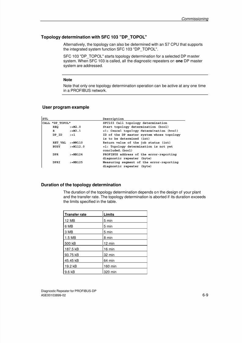
7/31/2019 Diagnose Repeater e
http://slidepdf.com/reader/full/diagnose-repeater-e 69/204
Commissioning
Diagnostic Repeater for PROFIBUS-DPA5E00103899-02 6-9
Topology determination with SFC 103 "DP_TOPOL"
Alternatively, the topology can also be determined with an S7 CPU that supportsthe integrated system function SFC 103 "DP_TOPOL".
SFC 103 "DP_TOPOL" starts topology determination for a selected DP master
system. When SFC 103 is called, all the diagnostic repeaters on one DP mastersystem are addressed.
Note
Note that only one topology determination operation can be active at any one timein a PROFIBUS network.
User program example
STL DescriptionCALL "DP_TOPOL" SFC103 Call topology determination
REQ :=M2.0 Start topology determination (bool)
R :=M2.1 =1: Cancel topology determination (bool)
DP_ID :=1 ID of the DP master system whose topology
is to be determined (int)
RET_VAL :=MW110 Return value of the job status (int)
BUSY :=M112.0 =1: Topology determination is not yet
concluded.(bool)
DPR :=MB124 PROFIBUS address of the error-reporting
diagnostic repeater (byte)
DPRI :=MB125 Measuring segment of the error-reporting
diagnostic repeater (byte)
Duration of the topology determination
The duration of the topology determination depends on the design of your plantand the transfer rate. The topology determination is aborted if its duration exceedsthe limits specified in the table.
Transfer rate Limits
12 MB 5 min
6 MB 5 min
3 MB 5 min
1.5 MB 8 min
500 kB 12 min
187.5 kB 16 min
93.75 kB 32 min
45.45 kB 64 min
19.2 kB 160 min
9.6 kB 320 min

7/31/2019 Diagnose Repeater e
http://slidepdf.com/reader/full/diagnose-repeater-e 70/204
Commissioning
Diagnostic Repeater for PROFIBUS-DP6-10 A5E00103899-02
Topology determination in the case of a pending line fault
Topology determination can only be carried out when there are no line faults in thenetwork.
If line faults exist at power on, topology determination cannot be carried out
successfully. The distance of the fault location to the diagnostic repeater is,however, always recorded and displayed.
The topology determination cannot be carried out until the fault has beeneliminated by the user.

7/31/2019 Diagnose Repeater e
http://slidepdf.com/reader/full/diagnose-repeater-e 71/204
Diagnostic Repeater for PROFIBUS-DPA5E00103899-02 7-1
7 Diagnostics
7.1 Overview
Overview
The diagnostic repeater allows rapid localization of line faults which occur duringthe operation at the PROFIBUS-DP.
Line faults are made visible by the LEDs at the diagnostic repeater.
A detailed diagnostic display is carried out via STEP 7 or COM PROFIBUS.With STEP 7 it is possible to display the following information for the diagnosticrepeater with the order number 6ES7 972-0AB01-0XA0:
• The topology as a graphic or in tabular form
• Diagnostic buffer
• Statistics buffer
In the user program this information can be read out and displayed on an HMIdevice, for example.
Which faults can the diagnostic repeater diagnose?
The diagnostic repeater recognizes the following types of faults:
• Break in the signal line A or B,• Short-circuit in the signal line A or B to shield,
• Missing terminators,
• Loose contacts,
• Invalid cascading depth,
• Two or more measuring circuits in a segment,
• Too many nodes in a segment,
• Node too far away from the diagnostic repeater,
• Faulty messages.
What cannot be diagnosed with certainty by the diagnostic repeater?
The following faults are not recognized with certainty:
• Non-energized terminators,
• Terminator connected, but there is no node,
• Additional terminator in a segment,
• Short circuit between signal line A and B.

7/31/2019 Diagnose Repeater e
http://slidepdf.com/reader/full/diagnose-repeater-e 72/204
Diagnostics
Diagnostic Repeater for PROFIBUS-DP7-2 A5E00103899-02
7.1.1 Diagnosis through LED display
Status and fault displays through LEDs
LED Color State Description
SF Red Off No fault
On Group error
BF Red Off No bus fault
Flashing • Slave is not configured or incorrectly
• Incorrect but still valid PROFIBUS address set
• Actual design does not agree with specified design
On Bus fault
DR Green Off Repeater function off (DR switch to OFF).
Flashing Baud rate search running.
On Baud rate found and repeater function on.
ON Green Off No voltage.
On Voltage is applied.
PG Yellow Off No bus activity at the programming-device interface.
Flashing Segment at the programming-device interface de-activated.
On Bus activity at the programming-device interface.
DP1 Yellow Off No bus activity at segment DP1.
Flashing The diagnostic repeater switched off segment DP1 automaticallysince it cannot detect any correct message frames(no signal level or signal level unstable).
On Bus activity at segment DP1.
DP2 Yellow Off No bus activity at segment DP2.
Flashing The diagnostic repeater switched off segment DP2 automaticallysince it cannot detect any correct message frames(no signal level or signal level unstable).
On Bus activity at segment DP2.
DP3 Yellow Off No bus activity on segment DP3 or segment DP3 switched off.
Flashing The diagnostic repeater switched off segment DP3 automaticallysince it cannot detect any correct message frames(no signal level or signal level unstable).
On Bus activity at segment DP3 recognized.
ERR DP2 Red Off There is no line fault at segment DP2.
Flashing The diagnostic repeater carries out an active line check at segmentDP2.
On There is a line fault at segment DP2.
ERR DP3 Red Off There is no line fault at segment DP3.
Flashing The diagnostic repeater carries out an active line check at segmentDP3.
On There is a line fault at segment DP3.

7/31/2019 Diagnose Repeater e
http://slidepdf.com/reader/full/diagnose-repeater-e 73/204
Diagnostics
Diagnostic Repeater for PROFIBUS-DPA5E00103899-02 7-3
Fault displays through LEDs
LED
SF BF DR ONMeaning Cause
Off Off Off Off No voltage Voltage not applied.
Off On Flashing On No connection to DPmaster
• Bus connection interrupted
• DP master does not exist / is de-activated
Off Flashing
On On Parameter assignmenterror,there is no dataexchange taking place.
• Slave is not configured or incorrectly
• Incorrect but still valid PROFIBUSaddress set
• Actual design does not agree withspecified design
On Off On On Error in the slave There is (at least) one diagnosis n the slave- the slave is exchanging data
Off Off On On Data exchange No faultFlashing Fla-
shingFlashing On PROFIBUS address Impermissible PROFIBUS address set: 0,
126, 127
Off/on Off/on/ fla-shing
Off On Repeater function off DR switch to OFF
7/31/2019 Diagnose Repeater e
http://slidepdf.com/reader/full/diagnose-repeater-e 74/204
Diagnostics
Diagnostic Repeater for PROFIBUS-DP7-4 A5E00103899-02
7.1.2 Diagnosis with STEP 7 and COM PROFIBUS
Requirements
In order to receive correct distance specifications in the diagnostic messages thetopology determination has to be updated after every change in the bus structure!
Visualizing the diagnosis
The diagnostic messages can be visualized for example by means of the followingtools and menu commands:
• STEP 7: PLC > Module Information
• Signal System Faults (at operator control and monitoring device)
• COM PROFIBUS: Service > Slave Diagnostics
• PROFIBUS Diagnostic Package (S7 diagnostic block FB 125)
Reporting system faults
Operator control and monitoring devices, for example OPs, are connected at thePROFIBUS or via the MPI interface to the CPU of the DP master. The operatorcontrol and monitoring device fetches the diagnostic information from this CPU.The message texts are generated in STEP 7 and can be visualized with theoperator control and monitoring devices.
Further information can be found in the manual Programming with Step 7 V 5.1 inthe section "Signaling System Faults"
Reading out current diagnostic messages
The diagnostic messages of the diagnostic repeater can be read out in the userprogram using SFC 13 "DP NRM_DG" and stored in the data area.
Further information can be found in the on-line help system of STEP 7.
S7 diagnostic block FB 125
The S7 diagnostic block can be found in the Internet under
http://www4.ad.siemens.de/view/cs/de/387257

7/31/2019 Diagnose Repeater e
http://slidepdf.com/reader/full/diagnose-repeater-e 75/204
Diagnostics
Diagnostic Repeater for PROFIBUS-DPA5E00103899-02 7-5
7.2 Structure of the diagnosis
7.2.1 Structure of the slave diagnosis
Byte 0 Station status 1
Byte 1 Station status 2
Byte 2 Node status 3
Byte 3 Master PROFIBUS address
Byte 4 Manufacturer identifier (high byte)
Byte 5 Manufacturer identifier (low byte)
Byte 6 Identifier-specific diagnosis
Byte 7 Identifier-specific diagnosis
Byte 8
.
.
Byte 26
Device-specific diagnosis: line fault status segment DP2
Byte 27..
Byte 45
Device-specific diagnosis: line fault status segment DP3
Byte 46..
Byte 64
Device-specific diagnosis: line fault status segment DP1
Byte 65
.
.
Byte 83
Device-specific diagnosis: line fault status programming device
interface
Byte 84..
Byte 90
Device-specific diagnosis: TSYNC diagnostic module
Note
The length of the diagnostic frame varies between 6, 27, 46, 65, 84 or 91 bytes.You can find out the length of the last diagnostic frame received in STEP 7 fromthe "RET_VAL" parameter of SFC 13.

7/31/2019 Diagnose Repeater e
http://slidepdf.com/reader/full/diagnose-repeater-e 76/204
Diagnostics
Diagnostic Repeater for PROFIBUS-DP7-6 A5E00103899-02
7.2.2 Node status 1 to 3
Definition
The node status 1 to 3 provides an overview of the state of a DP slave.
Station status 1
Bit Meaning Cause/remedy
0 1: The DP slave cannot be addressed by the DPmaster.
• Correct PROFIBUS address set at the DPslave?
• Bus connector connected?
• Voltage at DP slave?
• RS 485 repeater set correctly?
• Reset carried out at DP slave?
1 1: The DP slave is not yet ready for the dataexchange.
• Wait, since the DP slave is just startingup.
2 1: The configuration data sent from the DPmaster to the DP slave do not agree with thedesign of the DP slave.
• Correct design of the DP slave entered inthe configuration software? Evaluate theidentifier-specific diagnosis.
3 1: There is an extended diagnosis available.(group diagnosis display)
• Evaluate the device-specific diagnosis(line fault status). Bit 3 is reset as soon asall the faults have been eliminated. The bitis set again when a new diagnosticmessage exists in the bytes of the device-specific diagnosis.
4 1: The requested function is not supported by theDP slave (e.g. changing the PROFIBUSaddress via the software).
• Check the configuration.
5 1: DP master cannot interpret the answer of theDP slave.
• Check the bus design.
6 1: The DP slave type does not agree with thesoftware configuration.
• Correct node type entered in theconfiguration software?
7 1: The DP slave has been configured from adifferent DP master (not from the DP masterwhich currently has access to the DP slave).
• Bit is always 1 when you are e.g.accessing the DP slave with the PG orwith another DP master. The PROFIBUSaddress of the DP master whichconfigured the DP slave is contained inthe diagnostic byte "Master PROFIBUS
address".

7/31/2019 Diagnose Repeater e
http://slidepdf.com/reader/full/diagnose-repeater-e 77/204
Diagnostics
Diagnostic Repeater for PROFIBUS-DPA5E00103899-02 7-7
Station status 2
Bit Meaning
0 1: The DP slave has to be configured again.
1 1: There is a diagnostic message. The DP slave does not function unti l the faulthas been eliminated (static diagnostic message).
2 1: The bit is always set to 1 in the DP slave.
3 1: The response monitoring is activated at this DP slave.
4 1: The DP slave has received the control command "FREEZE".1
5 1: The DP slave has received the control command "SYNC".1
6 0: Bit is always set to 0.
7 1: The DP slave is de-activated, meaning that is has been removed from thecurrent processing.
1 The bit is updated only if another diagnostic message changes, too.
Node status 3
Bit Meaning
0 to 6 0: Bits are always set to 0.
7 1: • There are more diagnostic messages than the DP slave can save.
• The DP master cannot enter all the diagnostic messages sent by the DPslave in its diagnostic buffer (device-specific diagnosis)
7.2.3 Master PROFIBUS address
Definition
The diagnostic byte Master PROFIBUS address is contained in the PROFIBUSaddress of the DP master:
• Which has configured the DP slave and
• Which has reading and writing access to the DP slave.
The Master PROFIBUS address is contained in Byte 3 of the Slave diagnosis.

7/31/2019 Diagnose Repeater e
http://slidepdf.com/reader/full/diagnose-repeater-e 78/204
Diagnostics
Diagnostic Repeater for PROFIBUS-DP7-8 A5E00103899-02
7.2.4 Manufacturer identifier
Definition
The manufacturer ID contains a code that describes the type of the DP slave.
Manufacturer identifier
Byte 4 Byte 5 Manufacturer identifier for
80H A7H Diagnostic repeater
7.2.5 Structure of the module diagnosis
Definition
The identifier-specific diagnosis provides information on whether the diagnosticrepeater has been configured incorrectly or not. The identifier-specific diagnosisencompasses bytes 6 and 7.
Identifier-specific diagnosis
The identifier-specific diagnosis for the diagnostic repeater has the followingstructure:
Byte MSB
7 6 5 4 3 2 1 LSB
0
6 0 1 0 0 0 0 1 0 Code foridentifier-specificdiagnosis
Length of the identifier-specific diagnosis (2 bytes)
7 0 0 0 0 0 0 0 1
Events on the module are signaled by set bits.

7/31/2019 Diagnose Repeater e
http://slidepdf.com/reader/full/diagnose-repeater-e 79/204
Diagnostics
Diagnostic Repeater for PROFIBUS-DPA5E00103899-02 7-9
7.2.6 Structure of the device-specific diagnosis
Line fault status
The following section describes the structure of the line fault status of segmentsDP1, DP2, and DP3 and of the programming device interface.
Byte MSB
7 6 5 4 3 2 1 LSB
0
1 0 0 Block length = 19 Length
2 1 Status type line fault = 32 Type
3 0: Slot number Slot
4 res. Specifier
5 Segment res. res. res. res.
6Version res. res. LD Topo-logy
ON/ OFF
Seg-mentON/ OFF
res.
7 Fault rate
Errorinformation
8 Node x
9 Node y
10 Distance [0] from station x (high byte)
11 Distance [1] from station x (low byte)
12 Distance [0] from station y (high byte)
13 Distance [1] from station y (low byte)
14 Distance [0] from the diagnostic repeater (high byte)
15 Distance [1] from the diagnostic repeater (low byte)
Fault location
16 A.7 A.6 A.5 A.4 A.3 A.2 A.1 A.0
17 B.7 B.6 B.5 B.4 B.3 B.2 B.1 B.0
18 C.7 C.6 C.5 C.4 C.3 C.2 C.1 C.0
19 res.Error cause
res. Reserved bits are occupied with "0".

7/31/2019 Diagnose Repeater e
http://slidepdf.com/reader/full/diagnose-repeater-e 80/204
Diagnostics
Diagnostic Repeater for PROFIBUS-DP7-10 A5E00103899-02
Error information
Range Description
Segment Bit 4
Bit 5Bit 6
Bit 7
Segment DP3
Segment DP2Segment DP1
Programming device interface
0 Segment DP3 ONSegmentON/OFF
Bit 1
1 Segment DP3 OFF
0 Topology determination on DP2 or DP3 ONTopologyON/OFF
Bit 2
1 Topology determination on DP2 or DP3 OFF
0 There is no fault in the affected segment(all bits A.0 to C.7 = 0)
LD(line diagnosis)
Bit 3
1 There is a fault in the affected segment(at least one bit from A.0 to C.7 = 1)
Bit 6 01
DR 6ES7 972-0AB00-0XA0DR 6ES7 972-0AB01-0XA0
On the basis of the version, a software package can identify whether ornot the LD bit is to be evaluated.
Version
Bit 7 0 –
Fault rate Bit0 to 6
Value range from 0 to 100%
The value FFH means that there is no error rate for the relevant diagnosticevent.

7/31/2019 Diagnose Repeater e
http://slidepdf.com/reader/full/diagnose-repeater-e 81/204
Diagnostics
Diagnostic Repeater for PROFIBUS-DPA5E00103899-02 7-11
Fault location
The information on the fault location is only relevant to segments DP2 and DP3.
Range Description
Bit0 to 6
Addresses of the stations between which there is a line fault.
0 The distance specification of the node is not up to date.
The distance specification of a node is not up to date if topologydetermination has not been carried out after voltage recovery or for acertain period.
Station x,Station y
Bit 7
1 The distance specification of the node is up to date.
Distance[0, 1] from x
Bit0 to 7
Distance of the reflection point from node x.The specification is made in the unit "decimeters".
If either 7FH or FFH is entered in "station x", the parameter "Distance
[0, 1] from x" cannot be evaluated.Distance[0, 1] from y
Bit0 to 7
Distance of the reflection point from node y.The specification is made in the unit "decimeters".
If either 7FH or FFH is entered in "station y", the parameter "Distance[0, 1] from y" cannot be evaluated.
Distance[0, 1] from DR
Bit0 to 7
Distance of the reflection point from the diagnostic repeater.The specification is made in the unit "decimeters".
The value FFH means that the distance from the fault location to thediagnostic repeater cannot be specified for the relevant diagnostic event.
Special cases: area station x, station y
Special case Station x = ... Station y = ...
Fault point for one or more nodesto do with ≤measurement accuracy
Address of a node(representative)
FFH
Fault location before the first station Separate address First station
Fault location after the last station Last station 7FHFault location at a node Address of the node FFHFault location unknown FFH FFHFurther measuring circuit in thesegment
Separate station address Station connected toseparate station by meansof measuring circuit
Node too far away Separate station address Node too far awayMaximum cascade depth exceeded Separate station address Station at other end of the
cascade

7/31/2019 Diagnose Repeater e
http://slidepdf.com/reader/full/diagnose-repeater-e 82/204
Diagnostics
Diagnostic Repeater for PROFIBUS-DP7-12 A5E00103899-02
Error cause
Bit Description
A.0 1: Fault location and cause not clear
(possibly electromagnetic interference).A.1 1: -
A.2 1: -
A.3 1: Further measuring circuits at the segment, the other diagnostic repeater isconnected with its segment DP2.
A.4 1: Further measuring circuits at the segment, the other diagnostic repeater isconnected with its segment DP3.
A.5 1: –
A.6 1: Error cause is not clear.
A.7 1: Message fault rate is critical.
B.0 1: Break in the signal line A.
B.1 1: Short circuit between signal line B to screen.B.2 1: –
B.3 1: Short circuit between signal line A to screen.
B.4 1: Break in the signal line B.
B.5 1: –
B.6 1: Break in signal line A and/or B orno terminating resistor.
B.7 1: Short circuit between signal line A and/or B oran additional terminating resistor has been inserted.
C.0 1: Segment de-activated automatically, because line level constantly zero.
C.1 1: Segment de-activated automatically, because line level constantly unsteady.
C.2 1: –C.3 1: –
C.4 1: More than 32 nodes are connected to the measuring segment.
C.5 1: The distance of the node to the diagnostic repeater exceeds the permittedline length.
C.6 1: The maximum permitted number of diagnostic repeaters connected in seriesis exceeded.
C.7 1: The diagnostic repeater has recognized further faults.

7/31/2019 Diagnose Repeater e
http://slidepdf.com/reader/full/diagnose-repeater-e 83/204
Diagnostics
Diagnostic Repeater for PROFIBUS-DPA5E00103899-02 7-13
7.2.7 Monitoring function of the clocked PROFIBUS bus system
Diagnostic message
If the diagnostic repeater detects a TDX and/or TDP violation, it generates acorresponding diagnostic message. The diagnostic for the display of the TDX orTDP violation is structured as follows:
Byte MSB
7 6 5 4 3 2 1 LSB
0
1 0 0 Block length = 7 Length
2 1 Status type TSYNC fault = 33 (dec) Type
3 Slot number = 0 Slot
4 Reserved = 0 Specifier
5 Cycle counter [high] Cycle counter
6 Cycle counter [low]
7 TSYNC diagnostic status Errorinformation
Structure of error information: TSYNC diagnostic status
Bit Meaning
1 TDP violation detected in the cycle (see cycle counter)Bit 00 No TDP violation detected1 TDX violation detected in the cycle (see cycle counter)Bit 10 No TDX violation detected1 TSYNC parameter block error (times are not correct)Bit 20 TSYNC parameter block without error
Bits3 to 7
0 Reserved
Structure of input data: TSYNC diagnostic module
In order to establish a defined assignment from the diagnostic event to the relevantcycle, the cycle counter and a status byte can be displayed in the input area of thediagnostic repeater through the TSYNC diagnostic module.
The input data of the diagnostic repeater with the configured TSYNC diagnosticmodule are structured as follows:
Byte MSB
7 6 5 4 3 2 1 LSB
0
1 Cycle counter [high] 2 Cycle counter [low]
Cycle counter
3 TSYNC diagnostic status Errorinformation
The TSYNC diagnostic module has an output byte whose content is not evaluated.This is required for the detection of the TDX violation.

7/31/2019 Diagnose Repeater e
http://slidepdf.com/reader/full/diagnose-repeater-e 84/204
Diagnostics
Diagnostic Repeater for PROFIBUS-DP7-14 A5E00103899-02
7.3 Reading data out in the user program
The topology table, the diagnostic buffer, and the statistics buffer can be read outin the user program using SFC 59 "RD_REC" or SFB 52 "RDREC".
7.3.1 Topology table
Records
Recordnumber
(hex)
Recordnumber
(dec)
Writable/readable
W / R
Function
32H 50 R 1st part of the topology tableNodes 0 to 31; length = 170 bytes
33H 51 R 2nd part of the topology tableNodes 32 to 63; length = 170 bytes
34H 52 R 3rd part of the topology tableNodes 64 to 95; length = 170 bytes
35H 53 R 4th part of the topology tableNodes 96 to 126; length = 165 bytes
Structure of the topology table
Topology table record x Number of bytes
Constant 02 1 byte
Status information 1 1 byte
Time stamp 2 8 bytes
Topology entry x Status/substatus 1 byte
Distance (in decimeters) 2 bytes
Segment 1 byte
DR information
1 byte
...Topology entryx + 1
Topology entry ... ...
...Topology entryx + n (n = max. 32)
1 The status information is only contained in the first record. In the other recordsof the topology table this byte is occupied with 00H.
2 The time stamp is only contained in the first record. In the other records of thetopology table this entry is occupied with 00H.

7/31/2019 Diagnose Repeater e
http://slidepdf.com/reader/full/diagnose-repeater-e 85/204
Diagnostics
Diagnostic Repeater for PROFIBUS-DPA5E00103899-02 7-15
Status information
1 Topology determination on segment DP2 or DP2 OFFBit 0
0 Topology determination on segment DP2 ON
1 Topology determination on segment DP3 OFFBit 1
0 Topology determination on segment DP3 ON
1 Segment DP3 OFFBit 2
0 Segment DP3 ON
Bit 3 0 Reserved
0 No topology data available.Bit 4
1 Topology data available in the topology table.
Bits 5to 7
0 Reserved
Time stamp
Byte Time stamp Format
Bits 4-7 Bits 0-3
x Year Year BCD
x+1 Month Month BCD
x+2 Day Day BCD
x+3 Hour Hour BCD
x+4 Minute Minute BCD
x+5 Second Second BCD
x+6 Millisecond (high) Millisecond BCDx+7 Millisecond (low) Day of the week:
1 = Sunday2 = Monday3 = Tuesday4 = Wednesday5 = Thursday6 = Friday7 = Saturday
BCD
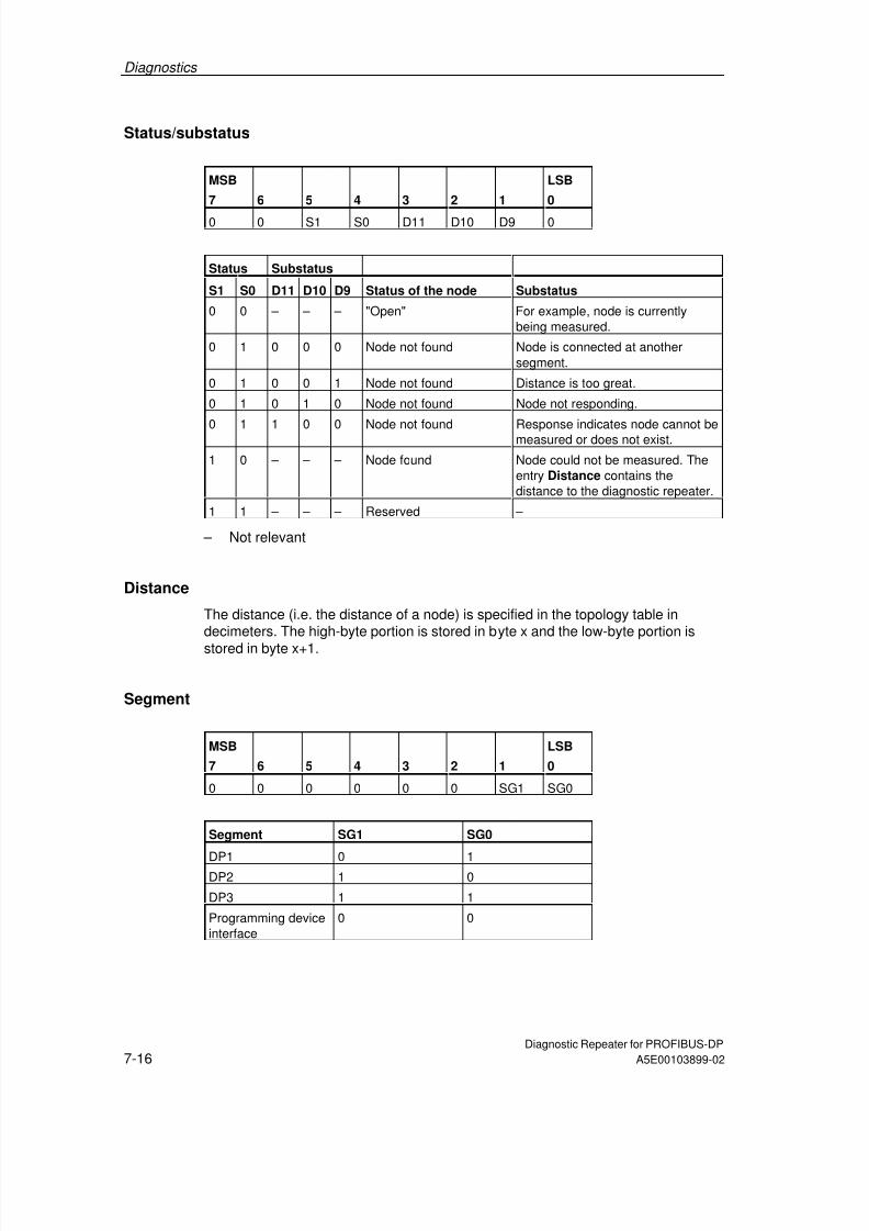
7/31/2019 Diagnose Repeater e
http://slidepdf.com/reader/full/diagnose-repeater-e 86/204
Diagnostics
Diagnostic Repeater for PROFIBUS-DP7-16 A5E00103899-02
Status/substatus
MSB
7 6
5
4
3
2
1
LSB
0
0 0 S1 S0 D11 D10 D9 0
Status Substatus
S1 S0 D11 D10 D9 Status of the node Substatus
0 0 – – – "Open" For example, node is currentlybeing measured.
0 1 0 0 0 Node not found Node is connected at anothersegment.
0 1 0 0 1 Node not found Distance is too great.
0 1 0 1 0 Node not found Node not responding.
0 1 1 0 0 Node not found Response indicates node cannot bemeasured or does not exist.
1 0 – – – Node found Node could not be measured. Theentry Distance contains thedistance to the diagnostic repeater.
1 1 – – – Reserved –
– Not relevant
Distance
The distance (i.e. the distance of a node) is specified in the topology table indecimeters. The high-byte portion is stored in byte x and the low-byte portion is
stored in byte x+1.
Segment
MSB
7 6
5
4
3
2
1
LSB
0
0 0 0 0 0 0 SG1 SG0
Segment SG1 SG0
DP1 0 1DP2 1 0
DP3 1 1
Programming deviceinterface
0 0

7/31/2019 Diagnose Repeater e
http://slidepdf.com/reader/full/diagnose-repeater-e 87/204
Diagnostics
Diagnostic Repeater for PROFIBUS-DPA5E00103899-02 7-17
DR information
MSB
7 6
5
4
3
2
1
LSB
0
DS1 DS0 ME KF 0 0 0 DR
DR - Diagnostic repeater
This bit is set when the response of a diagnostic repeater has been received.
KF - Cascade depth error
This bit is relevant only when DR=1. In this case, the relevant node is a diagnosticrepeater where the maximum permissible cascade depth has been exceeded.
ME - Measuring circuit
This bit is relevant only when DR=1. In this case, the node is a diagnostic repeater
connected to this diagnostic repeater and its segment SG1, SG0. If the bit is set,there are two measuring circuits in this segment.
DS0, DS1 - Diagnostic repeater segment
These bits are relevant only when DR=1. In this case, these bits indicate whichsegment of the other diagnostic repeater is connected to this diagnostic repeater.
Segment DS1 DS0
DP1 0 1
DP2 1 0
DP3 1 1
Programming deviceinterface
0 0
7.3.2 Diagnostic buffer
Records
Recordnumber
(hex)
Recordnumber
(dec)
Writable/readable
W / R
Function
1EH 30 R Diagnostic buffer DP1
1FH 31 R Diagnostic buffer DP2
20H 32 R Diagnostic buffer DP3
21H 33 R Diagnostic buffer PG(programming device)

7/31/2019 Diagnose Repeater e
http://slidepdf.com/reader/full/diagnose-repeater-e 88/204
Diagnostics
Diagnostic Repeater for PROFIBUS-DP7-18 A5E00103899-02
Structure of the diagnostic buffer
For each PROFIBUS segment the diagnostic repeater supplies a diagnostic bufferin which the last 10 events are stored together with their date and time.
Diagnostic buffer DPx Number of bytes
Constant 02 1 byte
Status information 1 byte
Segment data 1 byte
Number of entries 1 byte
Entry 1 Time stamp 8 bytes
Diagnostic entry x 15 bytes
Entry 2 Time stamp 8 bytes
Diagnostic entry x+1 15 bytes
Entry ... Time stamp 8 bytes
Diagnostic entry ... 15 bytesTime stamp 8 bytesEntry x + n
(n = max. 10) Diagnostic entry y 15 bytes
Status information
1 Topology determination on segment DP2 OFFBit 0
0 Topology determination on segment DP2 ON
1 Topology determination on segment DP3 OFFBit 1
0 Topology determination on segment DP3 ON
1 Segment DP3 OFFBit 20 Segment DP3 ON
1 Segment disturbed (at least one incoming error has yet not been reported asdeparted)
Bit 3
0 Segment not disturbed (all errors departed)
Bit 4to 7
0 Reserved
The status information is kept in accordance with the segment affected.
Segment Bit 0 Bit 1 Bit 2 Bit 3DP1 0 0 0 1/0
DP2 1/0 0 0 1/0
DP3 0 1/0 1/0 1/0
Programmingdevice interface
0 0 0 1/0

7/31/2019 Diagnose Repeater e
http://slidepdf.com/reader/full/diagnose-repeater-e 89/204
Diagnostics
Diagnostic Repeater for PROFIBUS-DPA5E00103899-02 7-19
Segment data
Bit0 to 3
0 Reserved
Bit 4 1 Segment: DP3Bit 5 1 Segment: DP2
Bit 6 1 Segment: DP1
Bit 7 1 Programming device interface
Number of entries
The "Number of entries" parameter indicates how many entries are contained inthe buffer. This information is necessary since, for a read request of 240 bytes, thediagnostic repeater always returns the full length of 234 bytes, regardless of thenumber of entries that exist.
If a read request is made and there is no entry in the buffer, the parameter"Number of entries" = 0, and the other bytes are filled with "0".
Time stamp
Time stamp Number of bytes
Bits 4-7 Bits 0-3
Year Year 1 byte
Month Month 1 byte
Day Day 1 byte
Hour Hour 1 byteMinute Minute 1 byte
Second Second 1 byte
Millisecond (high) Millisecond 1 byte
Millisecond (low) Day of the week:
1 = Sunday2 = Monday3 = Tuesday4 = Wednesday5 = Thursday6 = Friday7 = Saturday
1 byte

7/31/2019 Diagnose Repeater e
http://slidepdf.com/reader/full/diagnose-repeater-e 90/204
Diagnostics
Diagnostic Repeater for PROFIBUS-DP7-20 A5E00103899-02
Diagnostic entry
Byte MSB
7 6 5 4 3 2 1 LSB
0
1 Segment res. res. res. I/O
2
Version res. res. LD Topo-logyON/ OFF
Seg-mentON/ OFF
res.
3 Fault rate
Errorinformation
4 Node x
5 Node y
6 Distance [0] from station x (high byte)
7 Distance [1] from station x (low byte)
8 Distance [0] from station y (high byte)
9 Distance [1] from station y (low byte)10 Distance [0] from the diagnostic repeater (high byte)
11 Distance [1] from the diagnostic repeater (low byte)
Fault location
12 A.7 A.6 A.5 A.4 A.3 A.2 A.1 A.0
13 B.7 B.6 B.5 B.4 B.3 B.2 B.1 B.0
14 C.7 C.6 C.5 C.4 C.3 C.2 C.1 C.0
15 res.
Error cause
I/O Diagnostic event incoming (0)/ outgoing (1)
res. Reserved bits are occupied with "0".
The meaning of the remaining bits is described in Section 7.2.6.
7.3.3 Statistics buffer
Records
Record number
(hex)
Record number
(dec)
Writable/readable
W / R
Function
28H 40 R Reflection error rate DP2
29H 41 R Message frame error rate DP2
2AH 42 R Reflection error rate DP3
2BH 43 R Message frame error rate DP3

7/31/2019 Diagnose Repeater e
http://slidepdf.com/reader/full/diagnose-repeater-e 91/204
Diagnostics
Diagnostic Repeater for PROFIBUS-DPA5E00103899-02 7-21
Structure of the statistics buffer
Statistics buffer DPx Number of bytes
Constant 02 1 byte
Status information 1 byte
Segment data 1 byte
Number of entries 1 byte
Entry 1 Time stamp 8 bytes
Statistics entry x 1 byte
Entry 2 Time stamp 8 bytes
Statistics entry x+1 1 byte
Entry ... Time stamp 8 bytes
Statistics entry ... 1 byte
Time stamp 8 bytesEntry x + n(n = max. 26)
Statistics entry y 1 byte
Status information
1 Topology determination on segment DP2 or DP2 OFFBit 0
0 Topology determination on segment DP2 ON
1 Topology determination on segment DP3 OFFBit 1
0 Topology determination on segment DP3 ON
1 Segment DP3 OFFBit 2
0 Segment DP3 ON
1 Segment disturbed (at least one incoming error has yet not been reported asdeparted)
Bit 3
0 Segment not disturbed (all errors departed)
Bit 4to 7
0 Reserved
The status information is kept in accordance with the segment affected.
Segment Bit 0 Bit 1 Bit 2 Bit 3
DP1 0 0 0 1/0
DP2 1/0 0 0 1/0DP3 0 1/0 1/0 1/0
Programmingdevice interface
0 0 0 1/0

7/31/2019 Diagnose Repeater e
http://slidepdf.com/reader/full/diagnose-repeater-e 92/204
Diagnostics
Diagnostic Repeater for PROFIBUS-DP7-22 A5E00103899-02
Segment data
Bit0 to 3
0 Reserved
Bit 4 1 Segment: DP3Bit 5 1 Segment: DP2
Bit 6 1 Segment: DP1
Bit 7 1 Programming device interface
Number of entries
The "Number of entries" parameter indicates how many entries are contained inthe buffer. This information is necessary since, for a read request of 240 bytes, thediagnostic repeater always returns the full length of 238 bytes, regardless of thenumber of entries that exist.
If a read request is made and there is no entry in the buffer, the parameter"Number of entries" = 0, and the other bytes are filled with "0".
Time stamp
Byte Time stamp Format
Bits 4-7 Bits 0-3
x Year Year BCD
x+1 Month Month BCD
x+2 Day Day BCD
x+3 Hour Hour BCDx+4 Minute Minute BCD
x+5 Second Second BCD
x+6 Millisecond (high) Millisecond BCD
x+7 Millisecond (low) Day of the week:
1 = Sunday2 = Monday3 = Tuesday4 = Wednesday5 = Thursday6 = Friday7 = Saturday
BCD

7/31/2019 Diagnose Repeater e
http://slidepdf.com/reader/full/diagnose-repeater-e 93/204
Diagnostics
Diagnostic Repeater for PROFIBUS-DPA5E00103899-02 7-23
Statistics entry
The statistics entry contains the number of errored message frames as apercentage.
The statistics entries are formed as follows:
Reflection error rate =Message frames with reflections/number of message frames sent * 100
Message frame error rate =Message frames with bit errors/number of message frames received * 100
The entries in the statistics buffer (message frame and reflection errors) occur atregular intervals. The following update times apply between two entries, dependingon the baud rate:
Baud rate Update time
12 Mbps Approx. 300 ms
1.5 Mbps Approx. 180 ms500 kbps Approx. 1.54 s
187.5 kbps Approx. 1.54 s
19.2 kbps Approx. 3.2 s
9.6 kbps Approx. 3.2 s

7/31/2019 Diagnose Repeater e
http://slidepdf.com/reader/full/diagnose-repeater-e 94/204
Diagnostics
Diagnostic Repeater for PROFIBUS-DP7-24 A5E00103899-02
7.4 Topology display in STEP 7
7.4.1 Topology data: bus topology and topology table
Bus topology
The bus topology contains the following information:
• Nodes (master, slaves, diagnostic repeaters)
• Distance of the nodes from the diagnostic repeaters
The following functions are available:
• Show/hide segments
• Search for nodes
• Select nodes
The bus topology can be printed out and exported as a CSV file.
Procedure
1. In STEP 7 select the DP master system whose data you want to read.
2. Start the function by choosing the menu command View > Display > AllStations/Only Diagnostic Repeater with Stations/All Diagnostic RepeatersOnly.
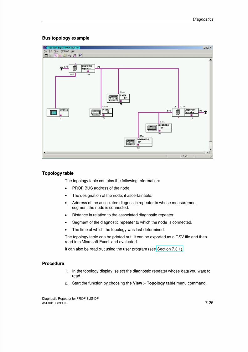
7/31/2019 Diagnose Repeater e
http://slidepdf.com/reader/full/diagnose-repeater-e 95/204
Diagnostics
Diagnostic Repeater for PROFIBUS-DPA5E00103899-02 7-25
Bus topology example
Topology table
The topology table contains the following information:
• PROFIBUS address of the node.
• The designation of the node, if ascertainable.
• Address of the associated diagnostic repeater to whose measurementsegment the node is connected.
• Distance in relation to the associated diagnostic repeater.
• Segment of the diagnostic repeater to which the node is connected.
• The time at which the topology was last determined.
The topology table can be printed out. It can be exported as a CSV file and thenread into Microsoft Excel and evaluated.
It can also be read out using the user program (see Section 7.3.1).
Procedure
1. In the topology display, select the diagnostic repeater whose data you want toread.
2. Start the function by choosing the View > Topology table menu command.

7/31/2019 Diagnose Repeater e
http://slidepdf.com/reader/full/diagnose-repeater-e 96/204
Diagnostics
Diagnostic Repeater for PROFIBUS-DP7-26 A5E00103899-02
Topology table example
7.4.2 Diagnostic buffer
For each of segments DP1, DP2, and DP3 as well as the programming device
interface, the diagnostic repeater contains a diagnostic buffer in which the last 10results are saved. The buffer contains the time, date, and a brief description of theresults. Incoming errors are marked with K or I, and outgoing errors are markedwith G or O.
The diagnostic buffers can be printed out. They can be exported as a CSV file andthen read into Microsoft Excel and evaluated.
The diagnostic buffers can also be read out using the user program (see Section7.3.2).
Procedure
1. In the topology display, select the diagnostic repeater whose data you want toread.
2. Start the function by choosing the Options > Diagnostic buffer menucommand.

7/31/2019 Diagnose Repeater e
http://slidepdf.com/reader/full/diagnose-repeater-e 97/204
Diagnostics
Diagnostic Repeater for PROFIBUS-DPA5E00103899-02 7-27
Diagnostic buffer example

7/31/2019 Diagnose Repeater e
http://slidepdf.com/reader/full/diagnose-repeater-e 98/204
Diagnostics
Diagnostic Repeater for PROFIBUS-DP7-28 A5E00103899-02
7.4.3 Statistics buffer
For each of segments DP2 and DP3 the diagnostic repeater contains a statisticsbuffer in which information on the reflection error rate and message frame errorrate is saved.
Reflection errors occur, for example, when the signal is reflected by a disturbed ordefective line.
Message frame errors are detected, for example, when message frames with parityerrors occur. Parity errors can be caused by a defective node, for example.
The values are displayed for a period of 60 seconds as of the point at which thedialog is opened. Other values are saved internally beyond this period.
The statistics buffers can be printed out. They can be exported as a CSV file andthen read into Microsoft Excel and evaluated.
The statistics buffers can also be read out using the user program (see Section7.3.3).
Procedure
1. In the topology display, select the diagnostic repeater whose data you want toread.
2. Start the function by choosing the Options > Statistics menu command.
Procedure in the event of line problems
If there are line problems, change to the diagnostic buffer to get information on thelocation and cause of the problem.
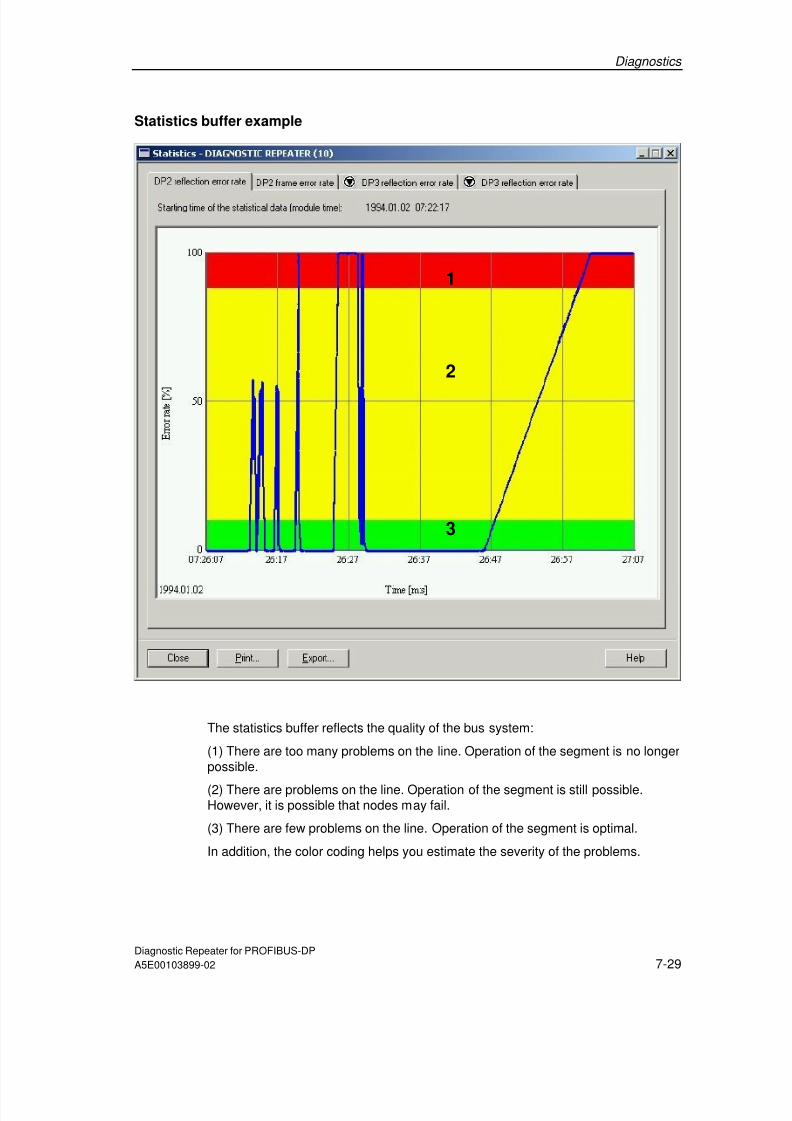
7/31/2019 Diagnose Repeater e
http://slidepdf.com/reader/full/diagnose-repeater-e 99/204
Diagnostics
Diagnostic Repeater for PROFIBUS-DPA5E00103899-02 7-29
Statistics buffer example
The statistics buffer reflects the quality of the bus system:
(1) There are too many problems on the line. Operation of the segment is no longerpossible.
(2) There are problems on the line. Operation of the segment is still possible.However, it is possible that nodes may fail.
(3) There are few problems on the line. Operation of the segment is optimal.
In addition, the color coding helps you estimate the severity of the problems.
1
2
3

7/31/2019 Diagnose Repeater e
http://slidepdf.com/reader/full/diagnose-repeater-e 100/204
Diagnostics
Diagnostic Repeater for PROFIBUS-DP7-30 A5E00103899-02
7.4.4 Error messages
Example of an error message
The figure below indicates how an error message is structured in STEP 7.
The tab cards DP1, DP2, DP3 and PG each contain the diagnostic information forthe corresponding segment. An icon indicates whether the segment is faulty or notand whether it is de-activated.
Three output fields contain graphic and text information on the fault location, typeof fault, remedy and, if appropriate, information on the reflection fault rate.
The "Details" command button leads to further information on the faults, fault causeand remedy.
Diagnostic Repeater,
reporting problem;DP2 indicates theaffected segment.
Fault locationon line
DP slavePB address 6
Segment problem Segment ok
Relative distance
Absolute distance offault point fromdiagnostic repeater
D:\SIMATIC300(1)\PB_Netz(4)

7/31/2019 Diagnose Repeater e
http://slidepdf.com/reader/full/diagnose-repeater-e 101/204
Diagnostics
Diagnostic Repeater for PROFIBUS-DPA5E00103899-02 7-31
Fault location: how exact is the distance information?
All distance specifications have a tolerance of ±1 m. The error can therefore alsohave occurred at neighboring nodes which lie within the tolerance to the specifiednode.
Reflection fault rate
The reflection fault rate specifies the number of messages at which a reflectionoccurred in the form of a percentage.
The reflection fault rate is indicated at the diagnostic messages.
7.5 Diagnostic messages and fault elimination
7.5.1 Design guidelines not observed
The following tables contain the diagnostic messages which are displayed inSTEP 7 and COM PROFIBUS.
More than 32 nodes are connected to the measuring segment
Description Remedy
A maximum of 32 nodes may be connected at aPROFIBUS segment. If this maximum isexceeded, the message traffic in this segment is
no longer ensured. The diagnostic repeater itselfalso counts as a node.
Note:
The SF LED shines red as soon as topologydetermination has been carried out.
Reduce the number of nodes at this segment.
If you use a further diagnostic repeater, you cancreate two further segments for 31 nodes each. Amaximum of 9 diagnostic repeaters can be connectedin series.
Carry out the topology determination again aftercompleting the changes.
If, contrary to the design guidelines of thediagnostic repeater, this segment contains acomponent with repeater function, such as anRS 485 repeater or an Optical Link Module (OLM),the nodes behind it are counted as well. This thenalso causes a fault message.
Note:The line diagnostic only functions up to thecomponent with repeater function. Everydownstream node is indicated with the distance ofthe component with repeater function.
Suppressing the fault message:
In this case, you can suppress the error message byswitching off topology determination for this segmentwhen configuring the diagnostic repeater (see Section6.3.2).

7/31/2019 Diagnose Repeater e
http://slidepdf.com/reader/full/diagnose-repeater-e 102/204
Diagnostics
Diagnostic Repeater for PROFIBUS-DP7-32 A5E00103899-02
The maximum permitted number of diagnostic repeaters connected in series isexceeded
Description Remedy
A maximum of 9 diagnostic repeaters can beconnected in series.
Note:
The SF LED shines red as soon as topologydetermination has been carried out.
Limit the number of diagnostic repeaters connected inseries to a maximum of 9.
Carry out the topology determination again aftercompleting the changes.
The distance of the node to the diagnostic repeater exceeds the permitted linelength
Description RemedyThe diagnostic repeater signals when a node istoo far away from it.
Note:
The SF LED shines red as soon as topologydetermination has been carried out.
Insert one or more diagnostic repeaters into thesegment so that the maximum line length which ispermissible and can be monitored of 100 m persegment is not exceeded.
More than one measurement circuit in segment
Description Remedy
A further diagnostic repeater with the interfaceDP2 or DP3 is connected.
The diagnostic repeater has two interfaces withmeasuring circuits (DP2 and DP3) and aninterface without measuring circuit (DP1). Nofurther measuring circuit may be connected tosegment DP2 or DP3. Further diagnosticrepeaters may only still be connected with theinterface DP1.
Note:
The SF LED shines red as soon as topology
determination has been carried out.
Change the network design so that further diagnosticrepeaters at this segment are only connected with theinterface DP1.
The programming device interface may only be usedto connect a programming device.
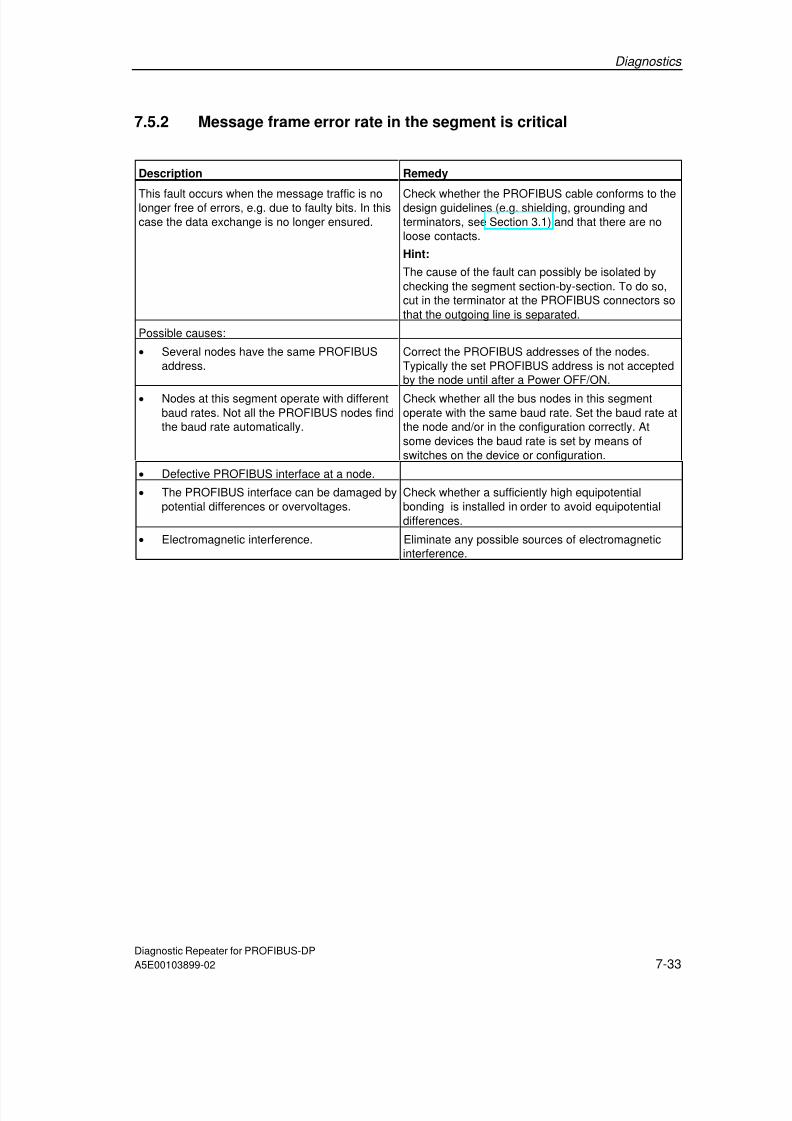
7/31/2019 Diagnose Repeater e
http://slidepdf.com/reader/full/diagnose-repeater-e 103/204
Diagnostics
Diagnostic Repeater for PROFIBUS-DPA5E00103899-02 7-33
7.5.2 Message frame error rate in the segment is critical
Description Remedy
This fault occurs when the message traffic is nolonger free of errors, e.g. due to faulty bits. In thiscase the data exchange is no longer ensured.
Check whether the PROFIBUS cable conforms to thedesign guidelines (e.g. shielding, grounding andterminators, see Section 3.1) and that there are noloose contacts.
Hint:
The cause of the fault can possibly be isolated bychecking the segment section-by-section. To do so,cut in the terminator at the PROFIBUS connectors sothat the outgoing line is separated.
Possible causes:
• Several nodes have the same PROFIBUSaddress.
Correct the PROFIBUS addresses of the nodes.Typically the set PROFIBUS address is not acceptedby the node until after a Power OFF/ON.
• Nodes at this segment operate with differentbaud rates. Not all the PROFIBUS nodes findthe baud rate automatically.
Check whether all the bus nodes in this segmentoperate with the same baud rate. Set the baud rate atthe node and/or in the configuration correctly. Atsome devices the baud rate is set by means ofswitches on the device or configuration.
• Defective PROFIBUS interface at a node.
• The PROFIBUS interface can be damaged bypotential differences or overvoltages.
Check whether a sufficiently high equipotentialbonding is installed in order to avoid equipotentialdifferences.
• Electromagnetic interference. Eliminate any possible sources of electromagneticinterference.

7/31/2019 Diagnose Repeater e
http://slidepdf.com/reader/full/diagnose-repeater-e 104/204
Diagnostics
Diagnostic Repeater for PROFIBUS-DP7-34 A5E00103899-02
7.5.3 Break in the signal wire A or B
Description Remedy
A wire break has occurred at the displayedlocation.
Possible causes:
• Damaged wire (e.g. high mechanical stress,vibration, bending radius too narrow),
• A signal wire not connected properly in thePROFIBUS connector,
• Mechanical stress can cause the signal wiresin the PROFIBUS connector to break or nolonger to contact,
• Defective PROFIBUS connector.
In the area of the displayed fault location check thesegment for:
• Damage to the wire,
• Correct mounting of the PROFIBUSconnectors/connections,
• Defective PROFIBUS node (e.g. through thedevice being switched off or my removing thePROFIBUS connector).
7.5.4 Short circuit in the signal wire A and B or short circuit in thesignal wire A or B to screen
Description Remedy
A wire short circuit has occurred at the displayedlocation.
Possible causes:
• Damaged wire (e.g. high mechanical stress,vibration, pinching, bending radius toonarrow),
• Signal wires not connected properly in thePROFIBUS connector,
• Ingress of conductive liquids,
• Badly stripped or loose braided shieldcontacts the signal wire,
• Defective PROFIBUS interface at theconnected node,
• Existing spur lines.
In the area of the displayed fault location check thesegment for:
• Damage to the wire,
• Correct mounting of the PROFIBUS connectorsconnections,
• Defective PROFIBUS node (e.g. through the
device being switched off or my removing thePROFIBUS connector),
• Spur lines.
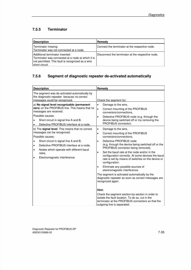
7/31/2019 Diagnose Repeater e
http://slidepdf.com/reader/full/diagnose-repeater-e 105/204
Diagnostics
Diagnostic Repeater for PROFIBUS-DPA5E00103899-02 7-35
7.5.5 Terminator
Description Remedy
Terminator missing:Terminator was not connected at a node. Connect the terminator at the respective node.
Additional terminator inserted:Terminator was connected at a node at which it isnot permitted. This fault is recognized as a wireshort circuit.
Disconnect the terminator at the respective node.
7.5.6 Segment of diagnostic repeater de-activated automatically
Description Remedy
The segment was de-activated automatically bythe diagnostic repeater because no correctmessages could be recognized. Check the segment for:
a) No signal level recognizable (permanentzero) on the PROFIBUS line. This means that nomessages are received.
Possible causes:
• Short circuit in signal line A and B.
• Defective PROFIBUS interface at a node.
• Damage to the wire,
• Correct mounting of the PROFIBUSconnectors/connections,
• Defective PROFIBUS node (e.g. through thedevice being switched off or my removing thePROFIBUS connector).
b) The signal level. This means that no correctmessages can be recognized.
Possible causes:
• Short circuit in signal line A and B,• Defective PROFIBUS interface at a node,
• Nodes which operate with different baudrates,
• Electromagnetic interference.
• Damage to the wire,
• Correct mounting of the PROFIBUSconnectors/connections,
• Defective PROFIBUS node(e.g. through the device being switched off or thePROFIBUS connector being removed),
• Set the baud rate at the node and/or in theconfiguration correctly. At some devices the baudrate is set by means of switches on the device orconfiguration.
• Eliminate any possible sources ofelectromagnetic interference.
The segment is activated automatically by thediagnostic repeater as soon as correct messages arerecognized again.
Hint:
Check the segment section-by-section in order toisolate the fault location. To do so, cut in theterminator at the PROFIBUS connectors so that theoutgoing line is separated.

7/31/2019 Diagnose Repeater e
http://slidepdf.com/reader/full/diagnose-repeater-e 106/204
Diagnostics
Diagnostic Repeater for PROFIBUS-DP7-36 A5E00103899-02
7.5.7 Fault cause or fault location not clear
The cause of the fault in the segment is not clear
Description Remedy
The reflection does not allow a clear faultrecognition.
There may be a loose contact or a multiple fault.
In the area of the displayed fault location check thesegment for:
• Damage to the wire,
• Correct mounting of the PROFIBUS connectors/ connections,
• Defective PROFIBUS node(e.g. through the device being switched off or thePROFIBUS connector being removed).
The location and cause of the fault in the segment are not clear
Description Remedy
The reflection does not allow a clear faultrecognition.
There may be a loose contact or anelectromagnetic interference.
Check whether the segment corresponds to thespecified guidelines (e.g. shielding, grounding orterminators, see Section 3.1).
Hint:
Check the segment section-by-section in order toisolate the fault location. To do so, cut in theterminator at the PROFIBUS connectors so that theoutgoing line is separated.
7.5.8 Fault cannot be evaluated
Description Remedy
The diagnostic repeater signals faults whichcannot be displayed by the version used of theconfiguration software.
The error types A.1, A.5, etc. are reserved forfuture enhancements.
Update your configuration software.

7/31/2019 Diagnose Repeater e
http://slidepdf.com/reader/full/diagnose-repeater-e 107/204
Diagnostics
Diagnostic Repeater for PROFIBUS-DPA5E00103899-02 7-37
7.5.9 Topology determination not possible
Errors in topology determination with STEP 7 or SFC 103 "DP_TOPOL" aredisplayed in conjunction with the diagnostic repeater with the order number6ES7972-0AB01-0XA0 and thus permit specific errors to be corrected.
• The list of "affected" diagnostic repeaters and the affected segment aredisplayed in STEP 7.
• When an S7 CPU is used with the integrated system function SFC 103"DP_TOPOL", the diagnostic repeater with the lowest address that has an erroris output in the user program.
This display is not possible with COM PROFIBUS or the diagnostic repeater withthe order number 6ES7972-0AB00-0XA0.

7/31/2019 Diagnose Repeater e
http://slidepdf.com/reader/full/diagnose-repeater-e 108/204
Diagnostics
Diagnostic Repeater for PROFIBUS-DP7-38 A5E00103899-02

7/31/2019 Diagnose Repeater e
http://slidepdf.com/reader/full/diagnose-repeater-e 109/204
Diagnostic Repeater for PROFIBUS-DP
A5E00103899-02 8-1
8 Technical Specifications
8.1 Standards and approvals
CE marking
Our products fulfill the requirements and protective aims of the following EU
guidelines and conform to the harmonized European Standards (EN) which were
published for programmable logic controllers in the gazettes of the European
Union:
73/23/EEC "Electrical equipment for use within certain voltage limits" (low-voltage
guideline)
89/336/EEC "Electromagnetic compatibility” (EMC guideline)
94/9/EC "Equipment and protective systems for use in explosive atmospheres"
(explosion protection guideline)
The EU declarations of conformity are kept available for the corresponding
authorities at:
Siemens Aktiengesellschaft
Bereich Automatisierungs- und Antriebstechnik
A&D AS RD 4
Postfach 1963
D-92209 Amberg
Underwriters Laboratories Inc. in accordance with1. UL 508 (Industrial Control Equipment)
2. CSA C22.2 No. 142 (Process Control Equipment)
3. UL 1604 (Hazardous Location)
4. CSA-213 (Hazardous Location)HAZ. LOC.

7/31/2019 Diagnose Repeater e
http://slidepdf.com/reader/full/diagnose-repeater-e 110/204
Technical Specifications
Diagnostic Repeater for PROFIBUS-DP8-2 A5E00103899-02
APPROVED for use inClass I, Division 2, Group A, B, C, D T4A;Class I, Zone 2, Group IIC T4
NoteYou will find the currently valid certificates and approvals on the type plate of thediagnostic repeater.
FM approval
Factory Mutual Research (FM) in accordance withApproval Standard Class Number 3611, 3600, 3810
APPROVED for use inClass I, Division 2, Group A, B, C, D T4AClass I, Zone II, Group IIC T4
In accordance with EN 50021 (Electrical apparatus for potentially explosiveatmospheres; Type of protection "n")
II 3 G EEx nA II T4
Marking for Australia
The diagnostic repeater fulfills the requirements of the standardAS/NZS 2064 (Class A).
IEC 61131
The diagnostic repeater fulfills the requirements and criteria of the IEC 61131-2standard (Programmable controllers, Part 2: Equipment requirements and tests).
PROFIBUS-DP
The diagnostic repeater fulfills the requirements and criteria of the PROFIBUS-DPV1 standard in accordance with IEC 61158:Ed3 Type 3 orIEC 61784-1:2002 Ed1 CP 3/1.

7/31/2019 Diagnose Repeater e
http://slidepdf.com/reader/full/diagnose-repeater-e 111/204
Technical Specifications
Diagnostic Repeater for PROFIBUS-DPA5E00103899-02 8-3
Approval for shipbuilding
Classification organizations:
ABS (American Bureau of Shipping)
BV (Bureau Veritas)DNV (Det Norske Veritas)
GL (Germanischer Lloyd)
LRS (Lloyds Register of Shipping)
Class NK (Nippon Kaiji Kyokai)
Use in industrial environments
SIMATIC products are designed for the use in industrial environments.
RequirementsArea of application
Emitted interference Noise immunity
Industry EN 61000-6-4: 2001 EN 61000-6-2: 2001
Use in residential environments
If you use the diagnostic repeater in residential areas, you must ensure it meetsthe requirements of limit value class B in accordance with EN 55011 with regard tothe emission of radio interference.
Suitable measures for meeting the requirements of limit value class B are:
Installation of the diagnostic repeater in grounded switch cabinets/boxesUse of filters in supply lines
!Warning
Damage to persons and material can occur.
In hazardous areas damage to persons and material can occur if you disconnectconnectors while operation is running.
Always de-energize the diagnostic repeater in hazardous areas before separating
connectors.

7/31/2019 Diagnose Repeater e
http://slidepdf.com/reader/full/diagnose-repeater-e 112/204
Technical Specifications
Diagnostic Repeater for PROFIBUS-DP8-4 A5E00103899-02
8.1.1 Electromagnetic compatibility of the diagnostic repeater
Definition
The electromagnetic compatibility is the ability of an electrical device to functionsatisfactorily in its electromagnetic environment without influencing thisenvironment.
The diagnostic repeater also fulfills the requirements of the EMC legislation of theEuropean Union.
The following sections provide information on the immunity to interference and onthe interference suppression.
Pulse-shaped interferences
The following table shows the electromagnetic compatibility of the diagnostic
repeater with regard to the pulse-shaped interferences. Prerequisite is that thesystem conforms to the specification and guidelines on electrical design.
Pulse-shaped interference Tested with Corresponds to severity
Electrostatic discharge in accordancewith IEC 61000-4-2
8 kV
4 kV
3 (air discharge)
2 (contact discharge)
Burst pulse (rapid transientdisturbances) to IEC 61000-4-4
2 kV (supply cable)
2 kV (signal cable)
3
Surge to IEC 61000-4-5
Only with protective elements
• Asymmetrical coupling
• Symmetric coupling
2 kV (supply cable)2 kV (signal line/data line)
1 kV (supply line)1 kV (signal line/data line)
3

7/31/2019 Diagnose Repeater e
http://slidepdf.com/reader/full/diagnose-repeater-e 113/204
Technical Specifications
Diagnostic Repeater for PROFIBUS-DPA5E00103899-02 8-5
Sine-shaped interference
RF irradiation to the device in accordance with IEC 61000-4-3:
Electromagnetic RF field, amplitude-modulated
- From 80 to 1000 MHz- 10 V/m
- 80% AM (1 kHz)
Electromagnetic RF field, pulse-modulated
- 900 ±5 MHz
- 10 V/m
- 50% ED
- 200 Hz repetition frequency
RF interference on signal and data cables, etc. to IEC 61000-4-6:
Radio frequency, asymmetrical, amplitude-modulated
- From 0.15 to 80 MHz
- 10 V root-mean-square value, unmodulated
- 80% AM (1 kHz)
- 150 Ohm source impedance
Emission of radio interferences
Emitted interference of electromagnetic fields in accordance with EN55011:Limit value class A, group 1 (measured at a distance of 30 m)
From 20 to 230 MHz < 30 dB (µV/m)Q
From 230 to 1000 MHz < 37 dB (µV/m)Q
Emitted interference via a.c. supply current to EN 55011: Limit value A, Group 1.
From 0.15 to 0.5 MHz < 79 dB (µV)Q, < 66 dB (µV)M
From 0.5 to 5 MHz < 73 dB (µV)Q, < 60 dB (µV)M
From 5 to 30 MHz < 73 dB (µV)Q, < 60 dB (µV)M

7/31/2019 Diagnose Repeater e
http://slidepdf.com/reader/full/diagnose-repeater-e 114/204
Technical Specifications
Diagnostic Repeater for PROFIBUS-DP8-6 A5E00103899-02
8.1.2 Mechanical and climatic ambient conditions for transportationand storage
Diagnostic repeaterThe diagnostic repeater exceeds the requirements of IEC 61131-2 with regard toshipping and storage conditions. The following information applies to diagnosticrepeaters that are transported and stored in the original packaging.
Ambient conditions Range of application Remarks
Free fall 0.3 m –
Temperature From -40 to 70°C –
Relative humidity From 5 to 95 % Without condensation
Air pressure From 1080 to 660 hPa Corresponds to a height of –1000 to 3500 m
8.1.3 Mechanical and climatic ambient conditions in operation
Conditions of use
The diagnostic repeater is intended for sheltered stationary use. The conditions ofuse exceed the requirements of IEC 61131-2.
The diagnostic repeater fulfills the conditions of use of Class 3C3 to DIN EN 60721
3-3 (points of use with high traffic density and directly adjacent to industrial plantswith chemical emissions).
Limitations
The diagnostic repeater may not be used without additional measures
At sites with a high share of ionizing radiation
At sites with severe operation conditions, for example by
- Dust development
- Corrosive vapors or gases.
In plants which require particular monitoring, such as for example- Elevator plants
- Electrical plants in particularly hazardous areas.
An additional measure for the use can be, for example, the installation of thediagnostic repeater in a cabinet.

7/31/2019 Diagnose Repeater e
http://slidepdf.com/reader/full/diagnose-repeater-e 115/204
Technical Specifications
Diagnostic Repeater for PROFIBUS-DPA5E00103899-02 8-7
Climatic environmental conditions
The diagnostic repeater may be used under the following ambient conditions:
Ambient conditions Range of application Remarks
Temperature:
• Horizontal installation:
• Vertical installation:
From 0 to 60 °C
From 0 to 40 °C
–
Relative humidity From 5 to 95 % Without condensation
Air pressure From 1080 to 795 hPa Corresponds to a height of –1000 to 2000 m
Pollutant concentrationSO 2 : < 0.5 ppm;relative humidity < 60 %,no condensation
H 2 S: < 0.1 ppm;
relative humidity < 60 %,no condensation
Test:10 ppm; 4 days
1 ppm; 4 days
Mechanical ambient conditions
The mechanical ambient conditions of the diagnostic repeater are specified in thefollowing table in the form of sinusoidal oscillation.
Frequency range (Hz) Continuous Occasional
10 <= f <= 58 0.0375 mm amplitude 0.075 mm amplitude
58 <= f <= 150 0.5 g constant acceleration 1 g constant acceleration
Reducing oscillations
If the diagnostic repeater is subject to larger impacts or oscillations, you have totake suitable measures to reduce the acceleration or the amplitude.
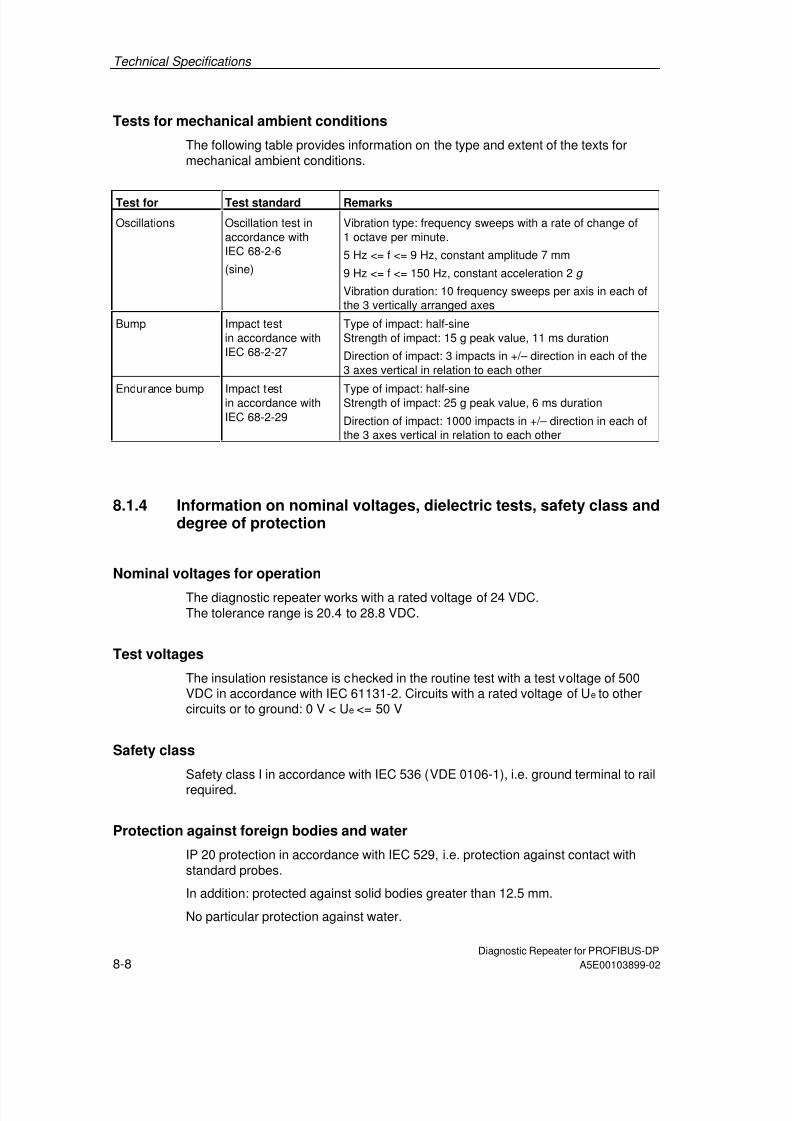
7/31/2019 Diagnose Repeater e
http://slidepdf.com/reader/full/diagnose-repeater-e 116/204
Technical Specifications
Diagnostic Repeater for PROFIBUS-DP8-8 A5E00103899-02
Tests for mechanical ambient conditions
The following table provides information on the type and extent of the texts formechanical ambient conditions.
Test for Test standard Remarks
Oscillations Oscillation test inaccordance withIEC 68-2-6
(sine)
Vibration type: frequency sweeps with a rate of change of1 octave per minute.
5 Hz <= f <= 9 Hz, constant amplitude 7 mm
9 Hz <= f <= 150 Hz, constant acceleration 2 g
Vibration duration: 10 frequency sweeps per axis in each ofthe 3 vertically arranged axes
Bump Impact testin accordance withIEC 68-2-27
Type of impact: half-sineStrength of impact: 15 g peak value, 11 ms duration
Direction of impact: 3 impacts in +/– direction in each of the3 axes vertical in relation to each other
Endurance bump Impact testin accordance withIEC 68-2-29
Type of impact: half-sineStrength of impact: 25 g peak value, 6 ms duration
Direction of impact: 1000 impacts in +/– direction in each ofthe 3 axes vertical in relation to each other
8.1.4 Information on nominal voltages, dielectric tests, safety class anddegree of protection
Nominal voltages for operation
The diagnostic repeater works with a rated voltage of 24 VDC.The tolerance range is 20.4 to 28.8 VDC.
Test voltages
The insulation resistance is checked in the routine test with a test voltage of 500VDC in accordance with IEC 61131-2. Circuits with a rated voltage of Ue to othercircuits or to ground: 0 V < Ue <= 50 V
Safety class
Safety class I in accordance with IEC 536 (VDE 0106-1), i.e. ground terminal to rail
required.
Protection against foreign bodies and water
IP 20 protection in accordance with IEC 529, i.e. protection against contact withstandard probes.
In addition: protected against solid bodies greater than 12.5 mm.
No particular protection against water.

7/31/2019 Diagnose Repeater e
http://slidepdf.com/reader/full/diagnose-repeater-e 117/204
Technical Specifications
Diagnostic Repeater for PROFIBUS-DPA5E00103899-02 8-9
8.2 Technical data of the diagnostic repeater
Dimensions and weight
Dimensions W x H x D (mm)• Without rail
• With rail
Weight
80 x 125 x 66.3
80 x 125 x 72.2
Approximately 300 g
Module-specific data
Bus protocol
Transfer rate to PROFIBUS-DP
Maximum permissible deviation betweenbit-sending and bit-receiving timing
Maximum cascading depth
Redundant operation
PROFIBUS-DP
9.6 kbps to 12 Mbps
±0.3% at 9.6 kbps to 500 kbps±0.03% at 1.5 Mbps to 12 Mbps
9 diagnostic repeaters
No
Distance information for line diagnosticsResolution
Accuracy
0.5 m
±1 m
Clock
Resolution
Accuracy
10 ms
Typically 5 s/h slow
Repeater throughput time
• Baud rates ≥ 1.5 Mbps
• Baud rates < 1.5 Mbps
Jitter
2.5 TBIT + 153 ns
0.5 TBIT +173 ns
1T = 1/48 MHz = 20.83 ns
Monitoring function of the clocked PROFIBUS bus system
DP bus cycle (TDP)Tolerance range TDP monitoring
Tolerance range T DX monitoring
min. 1 ms, max. 32 ms
±2 µs
±10 µs
Mechanical properties
Mounting possibilities
Degree of protection
DIN or S7-300 mounting rail
IP20
Bus cables
Termination system
Suitable cables
Fast Connect (insulation piercing technique,10 connecting cycles possible)
SIMATIC NET PROFIBUS cablesSee Appendix A
Cables for power supply
Termination system
Suitable cables
• Solid cable
• Flexible cable with wire end ferrule
• Flexible cable without wire end ferrule
Screw clamping
Solid and flexible cables
0.14 mm to 2.5 mm2
0.25 mm to 1.5 mm2
0.14 mm to 2.5 mm2

7/31/2019 Diagnose Repeater e
http://slidepdf.com/reader/full/diagnose-repeater-e 118/204
Technical Specifications
Diagnostic Repeater for PROFIBUS-DP8-10 A5E00103899-02
Dimensions and weight
Ambient conditions
Operating temperature
• Horizontal installation
• Vertical installationStorage temperature
Heat dissipation
0 to 60°C
0 to 40°C –40 to +70°C
Via housing without forced ventilation
Voltages, currents, potentials
Nominal supply voltage
• Static limits
• Dynamic limits
• Reverse polarity protection
• Power failure overriding
Control-to-load isolation
• Between the power supply and the PROFIBUS-
DP• Between segments DP1 and DP2, DP3
and programming device interface
• Between segments DP2, DP3and programming device interface
Insulation tested with
Power consumption at nominal voltage (24V DC)
• Without load at programming device interface
• Load at programming device interface(5V/90mA)
• Load at programming device interface(24V/100mA)
Power loss of the module
24 VDC
1. - 20.4 VDC to 28.8 VDC- 18.5 VDC to 30.2 VDC
Yes
5 ms
Yes
Yes
No
500 V DC
150 mA170 mA
250 mA
Typically 4 W
Status, alarms, diagnosis
Status display
Alarms
Diagnostic function
• Group error
• Bus fault
• Repeater function monitoring
• 24V voltage supply monitoring
• Bus activity programming device
• Bus activity segment DP1
• Bus activity segment DP2
• Bus activity segment DP3
• Monitoring segment DP2
• Monitoring segment DP3
Yes
None
Yes
Red LED SF
Red LED BF
Green LED DR
Green LED ON
Yellow LED PG
Yellow LED DP1
Yellow LED DP2
Yellow LED DP3
Red LED ERR DP2
Red LED ERR DP3

7/31/2019 Diagnose Repeater e
http://slidepdf.com/reader/full/diagnose-repeater-e 119/204
Technical Specifications
Diagnostic Repeater for PROFIBUS-DPA5E00103899-02 8-11
8.3 Records used in the diagnostic repeater
The table contains the records of the diagnostic repeater with the order number6ES7 972-0AB01-0XA0 that can be used by STEP 7 or in the user program. Otherrecords cannot be used.
Recordnumber
(hex)
Recordnumber
(dec)
Writable/readable
W / R
Function
1EH 30 R Diagnostic buffer DP1
1FH 31 R Diagnostic buffer DP2
20H 32 R Diagnostic buffer DP3
21H 33 R Diagnostic buffer PG (programming device)
28H 40 R Reflection error rate DP2
29H 41 R Message frame error rate DP2
2AH 42 R Reflection error rate DP32BH 43 R Message frame error rate DP3
32H 50 R 1st part of the topology table: nodes 0 to 31
33H 51 R 2nd part of the topology table: nodes 32 to 63
34H 52 R 3rd part of the topology table: nodes 64 to 95
35H 53 R 4th part of the topology table: nodes 96 to 126
3CH 60 W / R Time
The records can be accessed both via the C1 channel and the C2 channel onslot 0 or via the corresponding logical address (corresponds to the diagnostic
address in STEP 7).
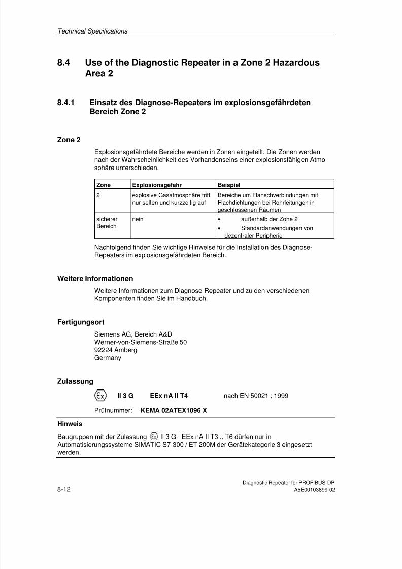
7/31/2019 Diagnose Repeater e
http://slidepdf.com/reader/full/diagnose-repeater-e 120/204
Technical Specifications
Diagnostic Repeater for PROFIBUS-DP8-12 A5E00103899-02
8.4 Use of the Diagnostic Repeater in a Zone 2 HazardousArea 2
8.4.1 Einsatz des Diagnose-Repeaters im explosionsgefährdetenBereich Zone 2
Zone 2
Explosionsgefährdete Bereiche werden in Zonen eingeteilt. Die Zonen werdennach der Wahrscheinlichkeit des Vorhandenseins einer explosionsfähigen Atmo-sphäre unterschieden.
Zone Explosionsgefahr Beispiel
2 explosive Gasatmosphäre trittnur selten und kurzzeitig auf
Bereiche um Flanschverbindungen mitFlachdichtungen bei Rohrleitungen ingeschlossenen Räumen
sichererBereich
nein • außerhalb der Zone 2
• Standardanwendungen vondezentraler Peripherie
Nachfolgend finden Sie wichtige Hinweise für die Installation des Diagnose-Repeaters im explosionsgefährdeten Bereich.
Weitere Informationen
Weitere Informationen zum Diagnose-Repeater und zu den verschiedenen
Komponenten finden Sie im Handbuch.
Fertigungsort
Siemens AG, Bereich A&DWerner-von-Siemens-Straße 5092224 AmbergGermany
Zulassung
II 3 G EEx nA II T4 nach EN 50021 : 1999Prüfnummer: KEMA 02ATEX1096 X
Hinweis
Baugruppen mit der Zulassung II 3 G EEx nA II T3 .. T6 dürfen nur inAutomatisierungssysteme SIMATIC S7-300 / ET 200M der Gerätekategorie 3 eingesetztwerden.

7/31/2019 Diagnose Repeater e
http://slidepdf.com/reader/full/diagnose-repeater-e 121/204
Technical Specifications
Diagnostic Repeater for PROFIBUS-DPA5E00103899-02 8-13
Instandhaltung
Für eine Reparatur muss die betroffene Komponente an den Fertigungsortgeschickt werden. Nur dort darf die Reparatur durchgeführt werden.
Besondere Bedingungen
1. Der Diagnose-Repeater muss in einen Schaltschrank oder ein metallischesGehäuse eingebaut werden. Diese müssen mindestens die Schutzart IP 54(nach EN 60529) gewährleisten. Dabei sind die Umgebungsbedingungen zuberücksichtigen, in denen das Gerät installiert wird. Für das Gehäuse musseine Herstellererklärung für Zone 2 vorliegen (gemäß EN 50021).
2. Wenn am Kabel bzw. an der Kabeleinführung dieses Gehäuses unter Betriebs-bedingungen eine Temperatur > 70 °C erreicht wird oder wenn unter Betriebs-bedingungen die Temperatur an der Aderverzweigung > 80 °C sein kann,müssen die Temperatureigenschaften der Kabel mit den tatsächlichgemessenen Temperaturen übereinstimmen.
3. Die eingesetzten Kabeleinführungen müssen der geforderten IP-Schutzart unddem Abschnitt 7.2 (gemäß EN 50021) entsprechen.
4. Alle Geräte, einschließlich Schalter etc., die an den Ein- und Ausgängen vonDiagnose-Repeatern angeschlossen werden, müssen für den ExplosionsschutzTyp EEx nA oder EEx nC genehmigt sein.
5. Es müssen Maßnahmen getroffen werden, dass die Nennspannung durchTransienten um nicht mehr als 40 % überschritten werden kann.
6. Umgebungstemperaturbereich: 0° C bis 60° C
7. Innerhalb des Gehäuses ist an einem nach dem Öffnen gut sichtbaren Platz einSchild mit folgender Warnung anzubringen:
WarnungDas Gehäuse darf nur kurze Zeit geöffnet werden, z. B. für visuelle Diagnose.Betätigen Sie dabei keine Schalter, ziehen oder stecken keine Baugruppen undtrennen keine elektrischen Leitungen (Steckverbindungen).Diese Warnung kann unberücksichtigt bleiben, wenn bekannt ist, dass keineexplosionsgefährdete Atmosphäre herrscht.
Liste der zugelassenen Baugruppen
Die Liste mit den zugelassenen Baugruppen finden Sie im Internet:
http://www4.ad.siemens.de/view/cs/
unter der Beitrags-ID 13702947.

7/31/2019 Diagnose Repeater e
http://slidepdf.com/reader/full/diagnose-repeater-e 122/204
Technical Specifications
Diagnostic Repeater for PROFIBUS-DP8-14 A5E00103899-02
8.4.2 Use of the Diagnostic Repeater in a Zone 2 Hazardous Area
Zone 2
Hazardous areas are divided up into zones. The zones are distinguished accordingto the probability of the existence of an explosive atmosphere. Zone Explosion Hazard Example
2 Explosive gas atmosphereoccurs only seldom and for ashort time
Areas around flange joints with flat gasketsin pipes in enclosed spaces
Safe area No • Outside zone 2
• Standard distributed I/Oapplications
Below you will find important information on the installation of the diagnosticrepeater in a hazardous area.
Further Information
You will find further information on the diagnostic repeater and the variouscomponents in the manual.
Production Location
Siemens AG, Bereich A&DWerner-von-Siemens-Straße 5092224 AmbergGermany
Certification
II 3 G EEx nA II T4 to EN 50021 : 1999
Test number: KEMA 02ATEX1096 X
Note
Modules with II 3 G EEx nA II T3 .. T6 certification can only be used inSIMATIC S7-300/ET 200M automation systems belonging to equipmentcategory 3.

7/31/2019 Diagnose Repeater e
http://slidepdf.com/reader/full/diagnose-repeater-e 123/204
Technical Specifications
Diagnostic Repeater for PROFIBUS-DPA5E00103899-02 8-15
Maintenance
If repair is necessary, the affected component must be sent to the productionlocation. Repairs can only be carried there.
Special Conditions
1. The diagnostic repeater must be installed in a cabinet or metal housing. Thesemust comply with the IP 54 degree of protection as a minimum. Theenvironmental conditions under which the equipment is installed must be takeninto account. There must be a manufacturer’s declaration for zone 2 availablefor the housing (in accordance with EN 50021).
2. If a temperature of > 70 °C is reached in the cable or at the cable entry of thishousing under operating conditions, or if a temperature of > 80 °C can bereached at the junction of the conductors under operating conditions, thetemperature-related properties of the cables must correspond to thetemperatures actually measured.
3. The cable entries used must comply with the required IP degree of protectionand Section 7.2 (in accordance with EN 50021).
4. All devices (including switches, etc.) that are connected to the inputs andoutputs of fail-safe signal modules must be approved for EEx nA or EEx nCexplosion protection.
5. Steps must be taken to ensure that the rated voltage through transients cannotbe exceeded by more than 40 %.
6. Ambient temperature range: 0° C to 60° C
7. A sign containing the following warning must be put up inside the housing in aneasily visible position when the housing is opened:
WarningThe housing can only be opened for a short time (e.g. for visual diagnostics). Ifyou do this, do not operate any switches, remove or install any modules ordisconnect any electrical cables (plug-in connections).You can disregard this warning if you know that the atmosphere is nothazardous (i.e. there is no risk of explosion).
List of Approved Modules
You will find the list of approved modules under the ID 13702947 on the Internet:
http://www4.ad.siemens.de/view/cs/ .

7/31/2019 Diagnose Repeater e
http://slidepdf.com/reader/full/diagnose-repeater-e 124/204
Technical Specifications
Diagnostic Repeater for PROFIBUS-DP8-16 A5E00103899-02
8.4.3 Utilisation du répéteur de diagnostic dans un environnement àrisque d'explosion en zone 2
Zone 2Les environnements à risque d'explosion sont répartis en zones. Les zones sedistinguent par la probabilité de présence d'une atmosphère explosive. Zone Risque d’explosion Exemple
2 Formation rare et brève d'uneatmosphère gazeuse explosive
Environnement de raccords à joints platsdans le cas de conduites dans des locauxfermés
Zone sûre Non • A l'extérieur de la zone 2
• Utilisation standard de périphériedécentralisée
Vous trouverez ci-après des remarques importantes pour l'installation du répéteurde diagnostic dans un environnement présentant un risque d'explosion.
Informations complémentaires
Des informations complémentaires sur le répéteur de diagnostic et les diversescomposantes se trouvent dans le manuel.
Lieu de production
Siemens AG, Bereich A&D
Werner-von-Siemens-Straße 5092224 AmbergGermany
Homologation
II 3 G EEx nA II T4 selon EN 50021 : 1999
Numéro de contrôle : KEMA 02ATEX1096 X
Nota
Les modules homologués II 3 G EEx nA II T3 .. T6 ne peuvent être utilisésque dans des automates SIMATIC S7-300 / ET 200M de catégorie 3.
7/31/2019 Diagnose Repeater e
http://slidepdf.com/reader/full/diagnose-repeater-e 125/204
Technical Specifications
Diagnostic Repeater for PROFIBUS-DPA5E00103899-02 8-17
Entretien
Si une réparation est nécessaire, la composante concernée doit être expédiée aulieu de production. La réparation ne doit être effectuée qu'en ce lieu.
Conditions particulières
1. Le répéteur de diagnostic doit être installé dans une armoire ou un boîtiermétallique. Ceux-ci doivent assurer au moins l'indice de protection IP 54. Il fautalors tenir compte des conditions d'environnement dans lesquelles l'appareilest installé. Le boîtier doit faire l’objet d’une déclaration de conformité dufabricant pour la zone 2 (selon EN 50021).
2. Si dans les conditions d’exploitation, une température > 70 °C est atteinte auniveau du câble ou de l’entrée du câble dans ce boîtier, ou bien si latempérature au niveau de la dérivation des conducteurs peut être > 80 °C, lescapacités de résistance thermique des câbles doivent corespondre auxtempératures effectivement mesurées.
3. Les entrées de câbles utilisées doivent avoir le niveau de protection IP exigé etêtre conformes au paragraphe 7.2 (selon EN 50021).
4. Tous les appareillages (y compris les interrupteurs, etc.) raccordés aux entréeset sorties de modules de signaux à sécurité intrinsèque doivent êtrehomologués pour la protection antidéflagrante type EEx nA ou EEx nC.
5. Il faut prendre des mesures pour que la tension nominale ne puisse pas êtredépassée de plus de 40% sous l’influence de transitoires.
6. Plage de température ambiante : 0° C à 60° C
7. A l’intérieur du boîtier, il faut placer, à un endroit bien visible après ouverture,une plaquette comportant l’avertissement suivant :
AvertissementOuvir le boîtier le moins longtemps possible, par exemple pour effectuer undiagnostic visuel. Ce faisant, n’actionnez aucun commutateur, ne déconnectezaucun module et ne débanchez pas de câbles électriques (connexions).Le respect de cet avertissement n’est pas impératif s’il est certain quel’environnement ne présente pas de risque d’explosion.
Liste des modules homologués
Vous trouverez sur Internet la liste des modules homologués :
http://www4.ad.siemens.de/view/cs/
référence ID 13702947.

7/31/2019 Diagnose Repeater e
http://slidepdf.com/reader/full/diagnose-repeater-e 126/204
Technical Specifications
Diagnostic Repeater for PROFIBUS-DP8-18 A5E00103899-02
8.4.4 Aplicación del repetidor para diagnóstico en áreas con peligro deexplosión, zona 2
Zona 2Las áreas con peligro de explosión se clasifican en zonas. Las zonas sediferencian según la probabilidad de la existencia de una atmósfera capaz de sufriruna explosión. Zona Peligro de explosión Ejemplo
2 La atmósfera explosiva de gassólo se presenta rara vez ymuy brevemente
Áreas alrededor de uniones abridadas con juntas planas en tuberías en localescerrados
Área segura no • fuera de la zona 2
• Aplicaciones estándar de laperiferia descentralizada
A continuación encontrará importantes informaciones para la instalación delrepetidor para diagnóstico en áreas con peligro de explosión.
Otras informaciones
Encontrará otras informaciones relativas al repetidor para diagnóstico y a losdistintos componentes en el Manual.
Lugar de fabricación
Siemens AG, Bereich A&DWerner-von-Siemens-Straße 5092224 AmbergGermany
Homologación
II 3 G EEx nA II T4 según norma EN 50021 : 1999
Número de comprobación: KEMA 02ATEX1096 X
Nota
Los módulos con la homologación II 3 G EEx nA II T3 .. T6 pueden utilizarseúnicamente en los autómatas programables SIMATIC S7-300 / ET 200M de lacategoría de equipo 3.

7/31/2019 Diagnose Repeater e
http://slidepdf.com/reader/full/diagnose-repeater-e 127/204
Technical Specifications
Diagnostic Repeater for PROFIBUS-DPA5E00103899-02 8-19
Mantenimiento
Para una reparación se ha de remitir el componente afectado al lugar defabricación. Sólo allí se puede realizar la reparación.
Condiciones especiales
1. El repetidor para diagnóstico se ha de montar en un armario eléctrico dedistribución o en una carcasa metálica. Éstos deben garantizar como mínimoel grado de protección IP 54. Para ello se han de tener en cuenta lascondiciones ambientales, en las cuales se instala el equipo. La caja deberácontar con una declaración del fabricante para la zona 2 (conforme aEN 50021).
2. Si durante la operación se alcanzara una temperatura > 70° C en el cable o laentrada de cables de esta caja o bien una temperatura > 80° C en labifurcación de hilos, deberán adaptarse las propiedades térmicas de los cablesa las temperaturas medidas efectivamente.
3. Las entradas de cable utilizadas deben cumplir el grado de protección IPexigido y lo expuesto en el apartado 7.2 (conforme a EN 50021).
4. Todos los dispositivos –inclusive interruptores, etc.– conectados a las entradasy salidas de módulos de señales de alta disponibilidad deben estarhomologados para la protección contra explosiones del tipo EEx nA o EEx nC.
5. Es necesario adoptar las medidas necesarias para evitar que la tensiónnominal pueda rebasar en más del 40 % debido a efectos transitorios.
6. Margen de temperatura ambiente: 0° C hasta 60° C
7. Dentro de la caja deberá colocarse en un lugar perfectamente visible tras suapertura un rótulo con la siguiente advertencia:
PrecauciónAbrir la caja sólo brevemente, p.ej. para el diagnóstico visual. Durante estetiempo Ud. no deberá activar ningún interruptor, desenchufar o enchufarmódulos ni separar conductores eléctricos (conexiones enchufables).Esta advertencia puede ignorarse si Ud. sabe que en la atmósfera existente nohay peligro de explosión.
Lista de los módulos homologados
En la internet hallará Ud. una lista con los módulos homologados:
http://www4.ad.siemens.de/view/cs/
bajo el ID de asignación 13702947.

7/31/2019 Diagnose Repeater e
http://slidepdf.com/reader/full/diagnose-repeater-e 128/204
Technical Specifications
Diagnostic Repeater for PROFIBUS-DP8-20 A5E00103899-02
8.4.5 Impiego del repeater di diagnostica nell’area a pericolo diesplosione zona 2
Zona 2Le aree a pericolo di esplosione vengono suddivise in zone. Le zone vengonodistinte secondo la probabilità della presenza di un'atmosfera esplosiva. Zona Pericolo di esplosione Esempio
2 L’atmosfera esplosiva sipresente solo raramente ebrevemente
Aree intorno a collegamenti a flange conguarnizioni piatte nelle condotte in ambientichiusi
Area sicura No • Al di fuori della zona 2
• Applicazioni standard di periferiadecentrata
Qui di seguito sono riportate delle avvertenze importanti per l'installazione delrepeater di diagnostica nell'area a pericolo di esplosione.
Ulteriori informazioni
Ulteriori informazioni sul repeater di diagnostica e sui diversi componenti si trovanonel manuale.
Luogo di produzione
Siemens AG, Bereich A&D
Werner-von-Siemens-Straße 5092224 AmbergGermany
Autorizzazione
II 3 G EEx nA II T4 secondo EN 50021 : 1999
Numero di controllo: KEMA 02ATEX1096 X
Avvertenza
Le unità con l'autorizzazione II 3 G EEx nA II T3 .. T6 possono essereimpiegate solo nei sistemi di controllori programmabili SIMATIC S7-300 / ET 200Mdella categoria di apparecchiature 3.

7/31/2019 Diagnose Repeater e
http://slidepdf.com/reader/full/diagnose-repeater-e 129/204
Technical Specifications
Diagnostic Repeater for PROFIBUS-DPA5E00103899-02 8-21
Manutenzione
Per una riparazione, il componente interessato deve essere inviato al luogo diproduzione. La riparazione può essere effettuata solo lì.
Condizioni particolari
1. Il repeater di diagnostica deve essere montata in un armadio elettrico o in uncontenitore metallico. Questi devono assicurare almeno il tipo di protezioneIP 54. In questo caso bisogna tenere conto delle condizioni ambientali nellequali l'apparecchiatura viene installata. Per il contenitore deve essere presenteuna dichiarazione del costruttore per la zona 2 (secondo EN 50021).
2. Se nei cavi o nel loro punto di ingresso in questo contenitore viene raggiunta incondizioni di esercizio una temperatura > 70 °C o se in condizioni di eserciziola temperatura nella derivazione dei fili può essere > 80 °C, le caratteristiche ditemperatura dei cavi devono essere conformi alla temperatura effettivamentemisurata.
3. Gli ingressi dei cavi usati devono essere conformi al tipo di protezione richiestoe alla sezione 7.2 (secondo EN 50021).
4. Tutte le apparecchiature, inclusi interruttori, ecc. che vengono collegati agliingressi/uscite di unità di segnale ad elevata sicurezza, devono essere statiomologati per la protezione da esplosione tipo EEx nA o EEx nC.
5. Devono essere prese delle misure per evitare che la tensione nominale possaessere superata per più del 40% da parte di transienti.
6. Campo termico ambientale: da 0° C a 60° C
7. All’interno del contenitore va apportata, in un luogo ben visibile dopo l’apertura,una targhetta con il seguente avvertimento:
AttenzioneIl contenitore può rimanere aperto solo per breve tempo, ad esempio per unadiagnostica a vista. In tal caso non azionare alcun interruttore, nondisinnestare o innestare unità e non staccare connessioni elettriche(connettori).Non è necessario tenere conto di questo avvertimento se è noto che non c’èun’atmosfera a rischio di esplosione.
Elenco delle unità abilitate
La lista con le unità omologate si trova in Internet al sito:
http://www4.ad.siemens.de/view/cs/
all’ID di voce 13702947.

7/31/2019 Diagnose Repeater e
http://slidepdf.com/reader/full/diagnose-repeater-e 130/204
Technical Specifications
Diagnostic Repeater for PROFIBUS-DP8-22 A5E00103899-02
8.4.6 Gebruik van de diagnose-repeater in het explosieve gebiedzone 2
Zone 2Explosieve gebieden worden ingedeeld in zones. Bij de zones wordtonderscheiden volgens de waarschijnlijkheid van de aanwezigheid van eenexplosieve atmosfeer. Zone Explosion Hazard Example
2 Een explosieve gasatmosfeertreedt maar zelden op en voorkorte duur
Gebieden rond flensverbindingen metpakkingen bij buisleidingen in geslotenvertrekken
Veiliggebied
neen • Buiten de zone 2
• Standaardtoepassingen vandecentrale periferie
Hierna vindt u belangrijke aanwijzingen voor de installatie van de diagnose-repeater in een explosief gebied.
Verdere informatie
In het handboek vindt u verdere informatie over de diagnose-repeater en deverschillende componenten.
Productieplaats
Siemens AG, Bereich A&DWerner-von-Siemens-Strasse 5092224 AmbergGermany
Vergunning
II 3 G EEx nA II T4 conform EN 50021 : 1999
Keuringsnummer: KEMA 02ATEX1096 X
Opmerking
Modulen met de vergunning II 3 G EEx nA II T3 .. T6 mogen slechts wordengebruikt in automatiseringssystemen SIMATIC S7-300 / ET 200M van deapparaatcategorie 3.

7/31/2019 Diagnose Repeater e
http://slidepdf.com/reader/full/diagnose-repeater-e 131/204
Technical Specifications
Diagnostic Repeater for PROFIBUS-DPA5E00103899-02 8-23
Instandhouding
De te herstellen component moet voor reparatie naar de plaats van vervaardigingworden gestuurd. Alleen daar mag de reparatie worden uitgevoerd.
Speciale voorwaarden
1. De diagnose-repeater moet worden ingebouwd in een schakelkast of in eenbehuizing van metaal. Deze moeten minstens de veiligheidsgraad IP 54waarborgen. Hierbij dient rekening te worden gehouden met deomgevingsvoorwaarden waarin het apparaat wordt geïnstalleerd. Voor debehuizing dient een verklaring van de fabrikant voor zone 2 te wordeningediend (volgens EN 50021).
2. Als aan de kabel of aan de kabelinvoering van deze behuizing onderbedrijfsomstandigheden een temperatuur wordt bereikt > 70 °C of als onderbedrijfsomstandigheden de temperatuur aan de adervertakking > 80 °C kanzijn, moeten de temperatuureigenschappen van de kabel overeenstemmen
met de werkelijk gemeten temperaturen.3. De aangebrachte kabelinvoeringen moeten de vereiste IP-veiligheidsgraad
hebben en in overeenstemming zijn met alinea 7.2 (volgens EN 50021).
4. Alle apparaten, schakelaars enz. inbegrepen, die worden aangesloten op dein- en uitgangen van tegen fouten beveiligde signaalmodulen, moeten zijngoedgekeurd voor de explosiebeveiliging type EEx nA of EEx nC.
5. Er dienen maatregelen te worden getroffen, zodat de nominale spanning doortransiënten met niet meer dan 40 % kan worden overschreden.
6. Omgevingstemperatuurbereik: 0° C tot 60° C
7. Binnen de behuizing dient op een na het openen goed zichtbare plaats een
bord te worden aangebracht met de volgende waarschuwing:WaarschuwingDe behuizing mag slechts voor korte tijd worden geopend, bijv. voor eenvisuele diagnose. Bedien hierbij geen schakelaar, trek of steek geen modulenen ontkoppel geen elektrische leidingen (steekverbindingen).Deze waarschuwing kan buiten beschouwing blijven, indien bekend is dat ergeen explosieve atmosfeer heerst.
Lijst van de toegelaten modulen
De lijst met de toegelaten modulen vindt u in het internet:
http://www4.ad.siemens.de/view/cs/
onder de bijdrage-ID 13702947.

7/31/2019 Diagnose Repeater e
http://slidepdf.com/reader/full/diagnose-repeater-e 132/204
Technical Specifications
Diagnostic Repeater for PROFIBUS-DP8-24 A5E00103899-02
8.4.7 Brug af diagnose-repeateren i det eksplosionsfarlige områdezone 2
Zone 2Eksplosionsfarlige områder inddeles i zoner. Zonerne adskiller sig indbyrdes efterhvor sandsynligt det er, at der er en eksplosiv atmosfære. Zone Eksplosionsfare Eksempel
2 Eksplosiv gasatmosfæreoptræder kun sjældent og varerkort
Områder rundt om flangeforbindelser medflade pakninger ved rørledninger i lukkederum
Sikkertområde
Nej • Uden for zone 2
• Standardanvendelser decentralperiferi
I det følgende findes vigtige henvisninger vedr. installation af diagnose-repeateren ieksplosionsfarligt område.
Yderligere informationer
Yderligere informationer om diagnose-repeateren og de forskellige komponenterfindes i manualen.
Produktionssted
Siemens AG, Bereich A&D
Werner-von-Siemens-Straße 5092224 AmbergGermany
Godkendelse
II 3 G EEx nA II T4 efter EN 50021 : 1999
Kontrolnummer: KEMA 02ATEX1096 X
Bemærk
Komponenter med godkendelsen II 3 G EEx nA II T3 .. T6 må kun monteres iautomatiseringssystemer SIMATIC S7-300 / ET 200M - udstyrskategori 3.

7/31/2019 Diagnose Repeater e
http://slidepdf.com/reader/full/diagnose-repeater-e 133/204
Technical Specifications
Diagnostic Repeater for PROFIBUS-DPA5E00103899-02 8-25
Vedligeholdelse
Skal den pågældende komponent repareres, bedes De sende den tilproduktionsstedet. Reparation må kun udføres der.
Særlige betingelser
1. Diagnose-repeateren skal monteres i et kontrolskab eller et metalkabinet.Disse skal mindst kunne sikre beskyttelsesklasse IP 54. I denne forbindelseskal der tages højde for de omgivelsestemperaturer, i hvilke udstyret erinstalleret. Der skal være udarbejdet en erklæring fra fabrikanten for kabinettetfor zone 2 (iht. EN 50021).
2. Hvis kablet eller kabelindføringen på dette hus når op på en temperatur på> 70 °C under driftsbetingelser eller hvis temperaturen på åreforegreningenkan være > 80 °C under driftsbetingelser, skal kablernestemperaturegenskaber stemme overens med de temperaturer, der rent faktiskmåles.
3. De benyttede kabelindføringer skal være i overensstemmelse med denkrævede IP-beskyttelsestype og afsnittet 7.2 (iht. EN 50021).
4. Alle apparater, inkl. kontakter osv., der forbindes med ind- og udgangene tilfejlsikre signalkomponenter, skal være godkendt til eksplosionsbeskyttelse aftype EEx nA eller EEx nC.
5. Der skal træffes foranstaltninger, der sørger for, at den nominelle spænding viatransienter ikke kan overskrides mere end 40 %.
6. Omgivelsestemperaturområde: 0° C til 60° C
7. I kabinettet skal der anbringes et skilt, der skal kunne ses, når kabinettetåbnes. Dette skilt skal have følgende advarsel:
AdvarselKabinettet må kun åbnes i kort tid, f.eks. til visuel diagnose. Tryk i denneforbindelse ikke på kontakter, træk eller isæt ikke komponenter og afbryd ikkeelektriske ledninger (stikforbindelser).Denne advarsel skal der ikke tages højde for, hvis man ved, at der ikke ernogen eksplosionsfarlig atmosfære.
Liste over godkendte komponenter
Listen med de godkendte komponenter findes på internettet:
http://www4.ad.siemens.de/view/cs/
under bidrags-ID 13702947.

7/31/2019 Diagnose Repeater e
http://slidepdf.com/reader/full/diagnose-repeater-e 134/204
Technical Specifications
Diagnostic Repeater for PROFIBUS-DP8-26 A5E00103899-02
8.4.8 Diagnoosi-toistimen käyttö räjähdysvaarannetuilla alueilla,vyöhyke 2
Vyöhyke 2Räjähdysvaarannetut alueet jaetaan vyöhykkeisiin. Vyöhykkeet erotellaanräjähdyskelpoisen ilmakehän olemassa olon todennäköisyyden mukaan. Vyöhyke Räjähdysvaara Esimerkki
2 Räjähtävä kaasuilmakehäilmaantuu vain harvoin jalyhytaikaisesti
Alueet putkistojen lattatiivisteillä varustuillalaippaliitoksilla suljetuissa tiloissa
turvallinenalue
ei • vyöhykkeen 2 ulkopuolella
• Hajautetun ulkopiirinvakiosovellukset
Seuraavasta löydätte tärkeitä ohjeita diagnoosi-toistimen asennukseenräjähdysvaarannetuilla alueilla.
Lisätietoja
Lisätietoja diagnoosi-toistimeen ja erilaisiin komponentteihin löydätte ohjekirjasta.
Valmistuspaikka
Siemens AG, Bereich A&DWerner-von-Siemens-Straße 50
92224 AmbergGermany
Hyväksyntä
II 3 G EEx nA II T4 EN 50021 mukaan: 1999
Tarkastusnumero: KEMA 02ATEX1096 X
Ohje
Rakenneryhmät hyväksynnän II 3 G EEx nA II T3 .. T6 kanssa saadaan
käyttää ainoastaan laitekategorian 3 automatisointijärjestelmissä SIMATIC S7-300 / ET 200M.

7/31/2019 Diagnose Repeater e
http://slidepdf.com/reader/full/diagnose-repeater-e 135/204
Technical Specifications
Diagnostic Repeater for PROFIBUS-DPA5E00103899-02 8-27
Kunnossapito
Korjausta varten täytyy kyseinen komponentti lähettää valmistuspaikkaan. Korjausvoidaan suorittaa ainoastaan siellä.
Erityiset vaatimukset
1. Diagnoosi-toistin täytyy asentaa kytkentäkaappiin tai metalliseen koteloon.Näiden täytyy olla vähintään kotelointiluokan IP 54 mukaisia. Tällöin onhuomioitava ympäristöolosuhteet, johon laite asennetaan. Kotelolle täytyy ollavalmistajaselvitys vyöhykettä 2 varten (EN 50021 mukaan).
2. Kun johdolla tai tämän kotelon johdon sisäänviennillä saavutetaan > 70 °Clämpötila tai kun käyttöolosuhteissa lämpötila voi piuhajaotuksella olla > 80 °C,täytyy johdon lämpötilaominaisuuksien vastata todellisesti mitattuja lämpötiloja.
3. Käytettyjen johtojen sisäänohjauksien täytyy olla vaaditun IP-kotelointiluokan jakohdan 7.2 (EN 50021 mukaan) mukaisia.
4. Kaikkien laitteiden, kytkimet jne. mukaan lukien, jotka liitetään virheiltäsuojattujen signaalirakenneryhmien tuloille ja lähdöille, täytyy olla hyväksyttyjätyypin EEx nA tai EEx nC räjähdyssuojausta varten.
5. Toimenpiteet täytyy suorittaa, ettei nimellisjännite voi transienttien kautta ylittyäenemmän kuin 40 %.
6. Ympäristölämpötila-alue: 0° C ... 60° C
7. Kotelon sisälle, avauksen jälkeen näkyvälle paikalle, on kiinnitettävä kilpi, jossa on seuraava varoitus:VaroitusKotelo saadaan avata ainoastaan lyhyeksi ajaksi, esim. visuaalista diagnoosiavarten. Älä tällöin käytä mitään kytkimiä, vedä tai liitä mitään rakenneryhmiä,
äläkä erota mitään sähköjohtoja (pistoliittimiä).Tätä varoitusta ei tarvitse huomioida, kun on tiedossa, että minkäänlaistaräjähdysvaarannettua ilmakehää ei ole olemassa.
Hyväksyttyjen rakenneryhmien lista
Lista hyväksiytyistä rakennesarjoista löytyy internetistä osoitteesta:
http://www4.ad.siemens.de/view/cs/
käyttäjätunnuksella 13702947.

7/31/2019 Diagnose Repeater e
http://slidepdf.com/reader/full/diagnose-repeater-e 136/204
Technical Specifications
Diagnostic Repeater for PROFIBUS-DP8-28 A5E00103899-02
8.4.9 Användning av diagnosrepeater i explosionsriskområde zon 2
Zon 2
Explosionsriskområden delas in i zoner. Zonerna delas in enligt sannolikheten atten atmosfär med explosionsfara föreligger. Zon Explosionsfara Exempel
2 Explosiv gasatmosfär uppstårendast sällan eller kortvarigt
Områden kring flänsförbindelser medpackningar vid rörledningar i slutnautrymmen
Säkertområde
Nej • Utanför zon 2
• Standardanvändning av decentralperiferi
Nedan följer viktiga anvisningar om installationen av diagnosrepeaterns
komponenter i ett explosionsriskområde.
Ytterligare information
Ytterligare information om diagnosrepeatern finner du i handboken.
Tillverkningsort
Siemens AG, Bereich A&DWerner-von-Siemens-Straße 5092224 Amberg
Germany
Godkännande
II 3 G EEx nA II T4 enligt EN 50021 : 1999
Kontrollnummer: KEMA 02ATEX1096 X
Anvisning
Komponentgrupper med godkännande II 3 G EEx nA II T3 .. T6 får endastanvändas i automatiseringssystemen SIMATIC S7-300 / ET°200M från
apparatgrupp 3.

7/31/2019 Diagnose Repeater e
http://slidepdf.com/reader/full/diagnose-repeater-e 137/204
Technical Specifications
Diagnostic Repeater for PROFIBUS-DPA5E00103899-02 8-29
Underhåll
Vid reparation måste den aktuella komponenten insändas til l tillverkaren.Reparationer får endast genomföras där.
Särskilda villkor
1. Diagnosrepeatern måste monteras i ett kopplingsskåp eller metallhus. Dessamåste minst vara av skyddsklass IP 54. Därvid ska omgivningsvillkoren därenheten installeras beaktas. För kåpan måste en tillverkardeklaration för zon 2föreligga (enligt EN 50021).
2. Om en temperatur på > 70°C uppnås vid husets kabel resp kabelinföring underdriftvillkor eller om temperaturen vid trådförgreningen kan vara > 80°C underdriftvillkor, måste kabelns temperaturegenskaper överensstämma med denverkligen uppmätta temperaturen.
3. De använda kabelinföringarna måste uppfylla kraven i det krävda IP-skyddsutförandet och i avsnitt 7.2 (enligt EN 50021).
4. Alla apparater, inklusive brytare osv, som ansluts till felsäkrade signalenhetersin- och utgångar, måste vara godkända för explosionsskydd av typ EEx nAeller EEx nC.
5. Åtgärder måste vidtas så, att märkspänningen ej kan överskridas med mer än40°% genom transienter.
6. Omgivningstemperatur: 0° C till 60° C
7. När huset öppnats ska en skylt med följande varning monteras på ett tydligtsynligt ställe huset:VarningHuset får endast öppnas under kort tid, t ex för visuell diagnos. Använd därvid
inga brytare, lossa eller anslut inga enheter och frånskilj inga elektriskaledningar (insticksanslutningar).Ingen hänsyn måste tas till denna varning om det är säkert att det inte rådernågon explosionsfarlig atmosfär.
Lista över godkända komponentgrupper
Lista över godkända enheter återfinns i Internet:
http://www4.ad.siemens.de/view/cs/
under bidrags-ID 13702947.

7/31/2019 Diagnose Repeater e
http://slidepdf.com/reader/full/diagnose-repeater-e 138/204
Technical Specifications
Diagnostic Repeater for PROFIBUS-DP8-30 A5E00103899-02
8.4.10 Uso do Diagnose-Repeaters em área exposta ao perigo deexplosão, zona 2
Zona 2As áreas expostas ao perigo de explosão são divididas em zonas. As zonas sãodiferenciadas de acordo com a probabilidade da existência de uma atmosferaexplosiva. Zona Perigo de explosão Exemplo
2 Só raramente e por um breveperíodo de tempo surgematmosferas explosivas
Áreas em torno de ligações flangeadas comvedações chatas em tubulações emrecintos fechados
Área segura não • fora da zona 2
• Aplicações descentralizadas deperiferia descentralizada
A seguir, encontrará avisos importantes para a instalação do repetidor paradiagnóstico em área exposta ao perigo de explosão.
Mais informações
Para obter mais informações sobre o Diagnose-Repeater e sobre os diversoscomponentes, consulte o manual.
Local de produção
Siemens AG, Bereich A&DWerner-von-Siemens-Straße 5092224 AmbergGermany
Licença
II 3 G EEx nA II T4 seg. EN 50021 : 1999
Número de ensaio: KEMA 02ATEX1096 X
Aviso
Componentes com a licença II 3 G EEx nA II T3 .. T6 só podem seraplicados em sistemas de automação SIMATIC S7-300 / ET 200M da categoria deaparelho 3.

7/31/2019 Diagnose Repeater e
http://slidepdf.com/reader/full/diagnose-repeater-e 139/204
Technical Specifications
Diagnostic Repeater for PROFIBUS-DPA5E00103899-02 8-31
Reparo
Os componentes em questão devem ser remetidos para o local de produção a fimde que seja realizado o reparo. Apenas lá deve ser efetuado o reparo.
Condições especiais
1. O repetidor para diagnóstico deve ser montado em um armário de distribuiçãoou em uma caixa metálica. Estes devem garantir no mínimo o tipo de proteçãoIP 54. Durante este trabalho deverão ser levados em consideração ascondições locais, nas quais o aparelho será instalado. Para a caixa deverá serapresentada uma declaração do fabricante para a zona 2 (de acordo comEN 50021).
2. Caso no cabo ou na entrada do cabo desta carcaça sob as condiçõesoperacionais seja atingida uma temperatura de > 70 °C, ou caso sobcondições operacionais a temperatura na ramificação do fio poderá atingir> 80 °C, as caraterísticas de temperatura deverão corresponder às
temperaturas realmente medidas.3. As entradas de cabo utilizadas devem corresponder ao tipo exigido de
proteção IP e à seção 7.2 (de acordo com o EN 50021).
4. Todos os aparelhos, inclusive as chaves, etc., que estejam conectadas ementradas e saídas de módulos de sinais protegidos contra erro, devem possuira licença para a proteção de explosão do tipo EEx nA ou EEx nC.
5. Precisam ser tomadas medidas para que a tensão nominal através detransitórios não possa ser ultrapassada em mais que 40 %.
6. Área de temperatura ambiente: 0° C até 60° C
7. No âmbito da carcaça deve ser colocada, após a abertura, em um ponto bem
visível uma placa com a seguinte advertência:AdvertênciaA carcaça deve ser aberta apenas por um breve período de tempo, por ex.para diagnóstico visual. Não acione nenhum interruptor, não retire ou conectenenhum módulo e não separe nenhum fio elétrico (ligações de tomada).Esta advertência poderá ser ignorada caso se saiba que não há nenhumaatmosfera sujeita ao perigo de explosão.
Lista dos componentes autorizados
A lista com os módulos autorizados encontram-se na Internet:
http://www4.ad.siemens.de/view/cs/
sob o número de ID 13702947.

7/31/2019 Diagnose Repeater e
http://slidepdf.com/reader/full/diagnose-repeater-e 140/204
Technical Specifications
Diagnostic Repeater for PROFIBUS-DP8-32 A5E00103899-02
8.4.11, 2
2.
.
2 ••••••••• •••••••••• ••••••••••••••••••• •••• •••••• ••• ••• •••••••••••••• ••••••••
•••••••• •••• ••• •••••••••• ••••••••• •• ••••••••• •••••••••••• •• ••••••••• ••••••
••••••• ••••••• ••• • ••••• ••• ••••• 2
• ••••••• ••••••••• •••••••••••••• •••••••••••
.
Siemens AG, Bereich A&DWerner-von-Siemens-Straße 50
92224 AmbergGermany
II 3 G EEx nA II T4
EN 50021 : 1999
: KEMA 02ATEX1096 X
II 3 G EEx nA II T3 .. T6SIMATIC S7-300 / ET 200M
3.

7/31/2019 Diagnose Repeater e
http://slidepdf.com/reader/full/diagnose-repeater-e 141/204
Technical Specifications
Diagnostic Repeater for PROFIBUS-DPA5E00103899-02 8-33
.
1.
,3
2 EN 50021).
2.70 °C
80 °C,
.3.
IP
EN 50021).
4.
EEx nA
EEx nC.
5.
%.
6. & C
7.
http://www4.ad.siemens.de/view/cs/

7/31/2019 Diagnose Repeater e
http://slidepdf.com/reader/full/diagnose-repeater-e 142/204
Technical Specifications
Diagnostic Repeater for PROFIBUS-DP8-34 A5E00103899-02

7/31/2019 Diagnose Repeater e
http://slidepdf.com/reader/full/diagnose-repeater-e 143/204
Diagnostic Repeater for PROFIBUS-DPA5E00103899-02 A-1
A Order Numbers
Diagnostic repeater and accessories
Designation Order number
Diagnostic repeater 6ES7972-0AB01-0XA0
SIMATIC S5/S7 connecting cable for 12 MbpsProgramming device connection to PROFIBUS-DP(active cable)
6ES7901-4BD00-0XA0
Fast-Connect stripping tool 6GK1905-6AA00BT200 Bus physics testing device for PROFIBUS-DP 6ES7181-0AA01-0AA0
PROFIBUS-DP bus connector
Designation Order number
PROFIBUS-DP bus connector (12 Mbps) 6ES7972-0BA12-0XA0
PROFIBUS-DP bus connector (12 Mbps) 6ES7972-0BB12-0XA0
PROFIBUS-DP bus connector (12 Mbps) 6ES7972-0BA41-0XA0
PROFIBUS-DP bus connector (12 Mbps) 6ES7972-0BB41-0XA0
PROFIBUS-DP bus connector (12 Mbps)Without programming device connector
6ES7972-0BA50-0XA0
PROFIBUS-DP bus connector (12 Mbps)With programming device connector
6ES7972-0BB50-0XA0
PROFIBUS-DP bus connector (12 Mbps)(with straight outgoing feeder)
6GK1500-0FC00
Note
If you are using other connectors, the design guidelines for the diagnostic repeaterrequire them to meet particular requirements (see Section 3.1.3).
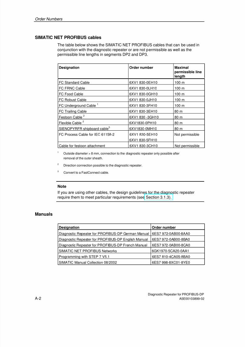
7/31/2019 Diagnose Repeater e
http://slidepdf.com/reader/full/diagnose-repeater-e 144/204
Order Numbers
Diagnostic Repeater for PROFIBUS-DPA-2 A5E00103899-02
SIMATIC NET PROFIBUS cables
The table below shows the SIMATIC NET PROFIBUS cables that can be used inconjunction with the diagnostic repeater or are not permissible as well as thepermissible line lengths in segments DP2 and DP3.
Designation Order number Maximalpermissible linelength
FC Standard Cable 6XV1 830-0EH10 100 m
FC FRNC Cable 6XV1 830-0LH10 100 m
FC Food Cable 6XV1 830-0GH10 100 m
FC Robust Cable 6XV1 830-0JH10 100 m
FC Underground Cable 1 6XV1 830-3FH10 100 m
FC Trailing Cable 6XV1 830-3EH10 80 m
Festoon Cable 2 6XV1 830 -3GH10 80 m
Flexible Cable 2 6XV1830-0PH10 80 mSIENOPYRFR shipboard cable3 6XV1830-0MH10 80 m
FC Process Cable for IEC 61158-2 6XV1 830-5EH10
6XV1 830-5FH10
Not permissible
Cable for festoon attachment 6XV1 830-3CH10 Not permissible
1 Outside diameter > 8 mm, connection to the diagnostic repeater only possible after
removal of the outer sheath.
2 Direction connection possible to the diagnostic repeater.
3 Convert to a FastConnect cable.
Note
If you are using other cables, the design guidelines for the diagnostic repeaterrequire them to meet particular requirements (see Section 3.1.3).
Manuals
Designation Order number
Diagnostic Repeater for PROFIBUS-DP German Manual 6ES7 972-0AB00-8AA0
Diagnostic Repeater for PROFIBUS-DP English Manual 6ES7 972-0AB00-8BA0
Diagnostic Repeater for PROFIBUS-DP French Manual 6ES7 972-0AB00-8CA0
SIMATIC NET PROFIBUS Networks 6GK1970-5CA20-0AA1
Programming with STEP 7 V5.1 6ES7 810-4CA05-8BA0
SIMATIC Manual Collection 08/2002 6ES7 998-8XC01-8YE0
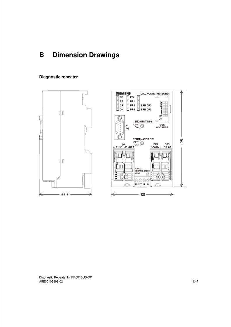
7/31/2019 Diagnose Repeater e
http://slidepdf.com/reader/full/diagnose-repeater-e 145/204
Diagnostic Repeater for PROFIBUS-DPA5E00103899-02 B-1
B Dimension Drawings
Diagnostic repeater
DIAGNOSTIC REPEATER
DP3
A3/B3
SEGMENT DP3
OFF
ON
TERMINATOR DP1
OFF
ON
X1
PG
DP2
A2/B2DP1
A1/B1 A1´/B1´
SF
BF
DR
ON
PG
DP1
DP2
DP3
ERR DP2
ERR DP3
BUS
ADDRESS
1 2 5
8066,3

7/31/2019 Diagnose Repeater e
http://slidepdf.com/reader/full/diagnose-repeater-e 146/204
Dimension Drawings
Diagnostic Repeater for PROFIBUS-DPB-2 A5E00103899-02

7/31/2019 Diagnose Repeater e
http://slidepdf.com/reader/full/diagnose-repeater-e 147/204
Diagnostic Repeater for PROFIBUS-DPA5E00103899-02 C-1
C User Questions
C.1 Topology and fault point determination
Is the topology determined automatically?
When an S7 CPU is used with the integrated system function SFC 103"DP_TOPOL", the topology can be determined automatically in the user program.
When any other CPU is used, the topology must be determined by the user usingSTEP 7 or COM PROFIBUS after any change to the plant. To do so use the menucommands
• PLC > PROFIBUS > Prepare Line Diagnostics in STEP 7 or
• Service > Prepare Line Diagnostics in COM PROFIBUS.
Can I read out the topology table?
In the case of diagnostic repeaters with the order number 6ES7 972-0AB01-0XA0you can read out the topology table.If you do not want to use the tabular rather than the graphical topology display,choose the following menu command in STEP 7 View > Topology table.
The topology table can also be read out with SFC 59 "RD_REC" or SFB 52"RDREC" using the user program (see Section 7.3).

7/31/2019 Diagnose Repeater e
http://slidepdf.com/reader/full/diagnose-repeater-e 148/204
User Questions
Diagnostic Repeater for PROFIBUS-DPC-2 A5E00103899-02
What is the effect of an excessive line length?
The diagnostic repeater can monitor a maximum line length of 100 m per segment(DP2, DP3) at baud rates of 9.6 kbps to 12 Mbps.
If this length is exceeded, the following diagnostic message appears: "The distance
from the node to the diagnostic repeater exceeds the permitted cable length".This diagnosis is generated the first time the topology is determined on the bus.The SF LED shines red. If the diagnostic repeater is switched off and on again, theLED goes out. The diagnostic message is not issued again until the next time thetopology is determined.
Remedy:
Insert one or more diagnostic repeaters into the segment so that the maximum linelength which is permissible and can be monitored of 100 m per segment is notexceeded.
What effect does a shield break have?A shield break is not detected by the diagnostic repeater.
How does topology determination take place when there are several diagnosticrepeaters in the line?
Up to nine diagnostic repeaters can be connected in series. Topologydetermination only has to be carried once for each PROFIBUS network.
The programming device/PC can be connected to any of the diagnostic repeatersin the PROFIBUS network.
A diagnostic repeater recognizes when it has another diagnostic repeater under it.
Can the diagnostic repeater diagnose two or more fault occurringsimultaneously at one segment?
The diagnostic repeater diagnoses the faults in the order in which they occur. Assoon as a signaled fault has been eliminated, the next one can be diagnosed.
A second fault which lies closer to the diagnostic repeater takes the place of thecurrent message.
In diagnostic repeaters as of order number 6ES7 972-0AB01-0XA0 there is anintegrated diagnostic buffer that stores the most recent diagnostic events for eachPROFIBUS segment (DP1, DP2, DP3, and programming device). This diagnostic
buffer can be read out from the CPU with SFC 59 "RD_REC" or SFB 52 "RDREC"using the user program (see Section 7.3).

7/31/2019 Diagnose Repeater e
http://slidepdf.com/reader/full/diagnose-repeater-e 149/204
User Questions
Diagnostic Repeater for PROFIBUS-DPA5E00103899-02 C-3
C.2 Diagnostic repeater / RS 485 repeater
What is the difference to the RS 485 repeater?
The diagnostic has new features not shared by the RS 485 repeater: the diagnosticfunction and the modeling as a DP slave.The slave functionality is required in order for the diagnostic repeater to send itsdiagnostic messages to the DP master.
Unlike the RS 485 repeater, the diagnostic repeater serves three segments: twodiagnostics-capable segments (each with 31 nodes) and one non-diagnostics-capable segment.
Can an RS 485 repeater simply be replaced by a diagnostic repeater?
Basically, yes. However, the diagnostic repeater requires more mounting space
and can only be used with certain restrictions together with RS 485 repeaters. Thediagnostic repeater has to be configured in the DP master and uses a PROFIBUSaddress. At a substitution the design guidelines of the diagnostic repeater have toobserved (see Section 3.1).
Is it possible to use diagnostic repeaters and RS 485 repeater together in oneplant?
Yes, if partially imperfect topology determination is acceptable and it is possible todo without line diagnostics after the RS 485 repeater (see Section 3.2).
Are there restrictions in comparison to the RS 485 repeater?All the restrictions apply irrespective of the set baud rate:
• Components with a repeater function such as the RS 485 repeater and OLMcan be used if partially imperfect topology determination is acceptable and it ispossible to do without line diagnostics after the component with a repeaterfunction.
• The maximum number of nodes at the PROFIBUS is reduced by the number ofdiagnostic repeaters used since the diagnostic repeater is itself a node andthus has its own PROFIBUS address and has to configured via the DP master.
• The maximum permissible cable length amounts to 100 m per segment (DP2,DP3).
• The diagnostic repeater may only be used in FMS and FDL networks withcertain limitations.
• The diagnostic repeater may not be used in pure MPI networks.

7/31/2019 Diagnose Repeater e
http://slidepdf.com/reader/full/diagnose-repeater-e 150/204
User Questions
Diagnostic Repeater for PROFIBUS-DPC-4 A5E00103899-02
C.3 Diagnostic repeater with different order numbers
Can diagnostic repeaters (6ES7972-0AB00-0XA0) be upgraded?
A firmware update is not possible to the functionality of the diagnostic repeater withthe order number 6ES7972-0AB01-0XA0.
What are the points to observe when replacing diagnostic repeaters?
When replacing a diagnostic repeater with the order number 6ES7972-0AB00-0XA0 with a diagnostic repeater with the order number 6ES7972-0AB01-0XA0,proceed as follows:
• Set the address on the diagnostic repeater,
• Switch the DR switch to ON,
• Carry out topology determination.
What should you watch out for when using diagnostic repeaters with differentversions in the same network?
The topology display in STEP 7 may be incomplete because the diagnosticrepeater with the order number 6ES7972-0AB00-0XA0 does not support thereading out of the topology.
If errors occur during topology determination, there is no feedback with thediagnostic repeater with the order number 6ES7972-0AB00-0XA0.

7/31/2019 Diagnose Repeater e
http://slidepdf.com/reader/full/diagnose-repeater-e 151/204
User Questions
Diagnostic Repeater for PROFIBUS-DPA5E00103899-02 C-5
C.4 Diagnostic messages
Why does the diagnostic repeater signal faults between nodes which do not
exist?
The physical structure of the segment has possibly changed since the lastdetermination of the topology. The topology table of the diagnostic repeater has notbeen updated yet.
The following are to be understood as changes in the physical structure:
• Change in the line lengths,
• Addition, removal of nodes or components with a repeater function,
• Change in node addresses.
Remedy:
Update the topology table of the diagnostic repeater.• To do this, choose PLC > PROFIBUS > Prepare Line Diagnostics in STEP 7
or
• in COM PROFIBUS Service > Prepare Line Diagnostics,
• When using an S7 CPU that supports the integrated system function SFC 103"DP_TOPOL", by using the user program.
Why is the specification of the distance inexact?
All distance specifications have a tolerance of ±1 m. The error can therefore alsohave occurred at neighboring nodes which lie within the tolerance to the specified
node.
Why can the cause of the fault not always be determined?
Some reflections do not allow a clear conclusion of what the cause of the fault is.The cause of the fault can be isolated by checking the respective segment section-by-section. To do so, cut in the terminator at the PROFIBUS connectors so that theoutgoing line is separated.

7/31/2019 Diagnose Repeater e
http://slidepdf.com/reader/full/diagnose-repeater-e 152/204
User Questions
Diagnostic Repeater for PROFIBUS-DPC-6 A5E00103899-02
Why is the distance to the fault point not specified exactly?
Every PROFIBUS node corresponds to an additional cable length of approx. 0.7 mwhich is contained in the distance specification. With certain diagnostic messages,for technical reasons the system may only be able to determine an absolute
distance between the diagnostic repeater and fault point, not taking into accountthe additional line length. The system indicates if the distance specification needsto be corrected.
Correction: Determine the number of nodes between the diagnostic repeater andthe fault location. Subtract 0.7 m per node from the distance specification.
Fault point = Distance specification – (0.7 m * Number of determined nodes)
Example: fault location = 25 m – (0.7 m x 10 nodes) = 18 m
Behavior of the diagnostic repeater after power on in the event of an error
Example:
• A node is removed from a plant during Power-off.
• During the work a line fault occurs at a point in the network due to a line break,without being noticed.
• The plant is switched on again.
The diagnostic repeater detects the line break. However, because of the change tothe plant, the distance specifications may not be correct.
The topology determination cannot be carried out until the fault has beeneliminated by the user.
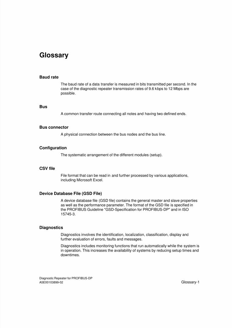
7/31/2019 Diagnose Repeater e
http://slidepdf.com/reader/full/diagnose-repeater-e 153/204
Diagnostic Repeater for PROFIBUS-DPA5E00103899-02 Glossary-1
Glossary
Baud rate
The baud rate of a data transfer is measured in bits transmitted per second. In thecase of the diagnostic repeater transmission rates of 9.6 kbps to 12 Mbps arepossible.
Bus
A common transfer route connecting all notes and having two defined ends.
Bus connector
A physical connection between the bus nodes and the bus line.
Configuration
The systematic arrangement of the different modules (setup).
CSV file
File format that can be read in and further processed by various applications,including Microsoft Excel.
Device Database File (GSD File)
A device database file (GSD file) contains the general master and slave propertiesas well as the performance parameter. The format of the GSD file is specified inthe PROFIBUS Guideline "GSD-Specification for PROFIBUS-DP" and in ISO15745-3.
Diagnostics
Diagnostics involves the identification, localization, classification, display andfurther evaluation of errors, faults and messages.
Diagnostics includes monitoring functions that run automatically while the system isin operation. This increases the availability of systems by reducing setup times anddowntimes.

7/31/2019 Diagnose Repeater e
http://slidepdf.com/reader/full/diagnose-repeater-e 154/204
Glossary
Diagnostic Repeater for PROFIBUS-DPGlossary-2 A5E00103899-02
DP master
The DP master carries out the communication with the DP slaves in the DP systemin accordance with a specified algorithm. To this purpose the DP master uses thefunctions specified at the PROFIBUS DP for communicating with the DP slaves.
DP slave
The DP slave can be addressed by the DP master. The DP slave makes specifiedfunctionalities (I/O data, diagnostics, etc.) available to the DP masters.
Electromagnetic compatibility
Electromagnetic compatibility is the ability of an electrical device to function fault-free in a specified environment without influencing the environment in a mannerwhich is not permissible.
Equipotential bonding
Electrical connection (equipotential bonding conductor) that brings the exposedconductive parts of electrical equipment and other conductive parts to the same orapproximately the same potential in order to prevent troublesome or dangerousvoltages arising between these parts.
Ground
The conductive mass of earth, the electrical potential of which is equivalent to zero.In the vicinity of grounding electrodes, the potential may not be zero. The term"reference ground" is often used here.
HMI
Abbreviation for Human Machine Interface. Operator control and monitoring devicefor effective dialog between humans and machine, for example, SIMATIC OperatorPanels (OP), SIMATIC Touch Panels (TP).
Master
When it has a token, a master can send data to and request data from other nodes(active nodes). The CPU 315–2 DP is an example of a DP master.
Node
Device which can send and/or receive data via the bus, for example a DP masteror a DP slave. This device requires a unique PROFIBUS address to this purpose.

7/31/2019 Diagnose Repeater e
http://slidepdf.com/reader/full/diagnose-repeater-e 155/204
Glossary
Diagnostic Repeater for PROFIBUS-DPA5E00103899-02 Glossary-3
Parameter configuration
Parameter configuration is the setting of parameters for the slave, master or furtherones for modules.
PROFIBUS
PROcess FIeld BUS; field bus standard defined in IEC 61158:Ed3 Type 3 and IEC61784-1:2002 Ed1 CP 3/1. It defines the functional, electrical, and mechanicalproperties of a bit serial field bus system.
PROFIBUS address
Each bus node must receive a PROFIBUS address so that it can be uniquelyidentified on PROFIBUS-DP.
PCs/programming devices have the PROFIBUS address "0".
DP masters and DP slaves have a PROFIBUS address in the range of 1 to 125.
PROFIBUS DP
PROFIBUS bus system with the protocol DP. DP stands for Distributed I/Odevices.
Reference potential
Potential from which the voltages of the circuits involved can be observed and/ormeasured.
Segment
The bus line between two terminating resistors forms a segment. A segment cancontain up to 32 bus nodes. Segments can be connected, for example, via RS 485Repeaters or diagnostic repeaters.
Slave
A slave may only exchange data with a master after it has been prompted by themaster to do so. Slaves are, for example, all the DP slaves such as ET 200B, ET200X, ET 200M, ET 200S, diagnostic repeater.

7/31/2019 Diagnose Repeater e
http://slidepdf.com/reader/full/diagnose-repeater-e 156/204
Glossary
Diagnostic Repeater for PROFIBUS-DPGlossary-4 A5E00103899-02
Terminator
A terminator is a resistor used to terminate the data transfer cable in order to avoidreflections.
Ungrounded
Without electrical connection to ground.

7/31/2019 Diagnose Repeater e
http://slidepdf.com/reader/full/diagnose-repeater-e 157/204
Diagnostic Repeater for PROFIBUS-DPA5E00103899-02 Index-1
Index
A
Absolute distance...........................................1-8Absolute distance specification ....................3-20Absolute distance specification, example.....7-30Accessories................................................... A-1Active cables ..................................................3-6Addressing .....................................................6-1Alarms..........................................................8-10Ambient conditions.......................................8-10Approvals .......................................................8-1
Arrangement of the DP master.......................3-8Available functions
with COM PROFIBUS ................................6-3with STEP 7................................................6-3
BBaud rate........................................................8-9
correct ......................................................7-35search ........................................................2-1
Behavior in the event of an error................... .2-1Block diagram ................................................5-5Break in the signal wire ................................7-34BT 200..........................................................3-19
BUS ADDRESS (switch) ................................1-6Bus cables...............................................5-3, 8-9Bus components
with a repeater function ............................3-12with repeater function ...............................3-12
Bus connectors ..............................................3-3Bus faults .....................................................3-13Bus terminal
RS 485 ................................................3-2, 3-6
C
Cable lengthmaximum....................................................3-5
Cable types ............................................ 5-2, A-2
power supply ..............................................8-9Cables ............................................................3-3Cascading depth ............................................3-5CE marking ....................................................8-1Changes
to plants.............................................1-8, 3-20Changes in the physical structure .................C-5Changing the address ....................................6-2Classification organizations............................8-3Clock synchronization ....................................6-5
Clocked interrupt............................................ 6-5Clocked PROFIBUS bus system
features...................................................... 2-6COM PROFIBUS
menu command for diagnostics................. 7-4menu command for topology determination1-8versions ..................................................... 6-3
Commissioning.............................................. 6-8Commissioning/service.................................. 2-2Components
with integrated section monitoring ........... 3-13with repeater function .............................. 3-12
Components with a repeater function ......... ...C-3Components with repeater function ............. 3-12Conditions of use during operation .......... ...... 8-6Configuration ................................................. 6-5
example ................................................... 3-10Connecting PG/PC ........................................ 6-8Connecting PGs............................................. 6-8Connecting PROFIBUS bus lines .................. 5-3Connections................................................... 5-4Contacting cover............................................ 5-3Control-to-load isolation................................. 5-6Conversion to FC cables ............................... 3-4Copper networks............................................ 3-1Correction of the distance specification .........C-6CSV file.......................................................... 2-2
C-Tick mark ................................................... 8-2Currents....................................................... 8-10
D
Data photoelectric barriers........................... 3-12DDB............................................................... 6-4Degree of protection ...................................... 1-3Design guidelines
diagnostic repeaters .................................. 3-1PROFIBUS networks ................................. 3-1
Determining the topologycarrying out................................................ 1-8deactivating.............................................. 3-13
Diagnosable faults ......................................... 7-1Diagnostic block FB 125 ................................ 7-4Diagnostic buffer............................................ 2-2
example ................................................... 7-27STEP 7 .................................................... 7-26user program ........................................... 7-17
Diagnostic concept ...................................... 3-19Diagnostic message
reading out................................................. 7-4Diagnostic message frame length.................. 6-6Diagnostic package ....................................... 7-4
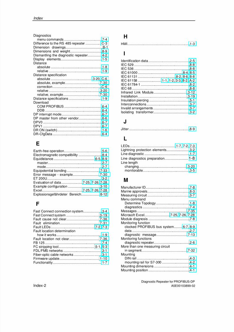
7/31/2019 Diagnose Repeater e
http://slidepdf.com/reader/full/diagnose-repeater-e 158/204
Index
Diagnostic Repeater for PROFIBUS-DPIndex-2 A5E00103899-02
Diagnosticsmenu commands ....................................... 7-4
Difference to the RS 485 repeater .................C-3Dimension drawings.......................................B-1Dimensions and weight.................................. 8-9Dismantling the diagnostic repeater............... 4-2Display elements............................................ 1-5Distance
absolute .....................................................1-8relative .......................................................1-9
Distance specificationabsolute ........................................... 3-20, C-6absolute, example....................................7-30correction ...................................................C-6relative .....................................................3-20relative, example......................................7-30
Distance specifications .................................. 1-9Download
COM PROFIBUS .......................................6-4DDB ........................................................... 6-4
DP interrupt mode.......................................... 6-7DP master from other vendor......................... 6-6DPV0 ............................................................. 6-7DPV1 ............................................................. 6-7DR ON (switch) .............................................. 1-6DR-CfgData ...................................................6-4
EEarth-free operation....................................... 5-6Electromagnetic compatibility ........................ 8-4Equidistance ........................................... 6-5, 8-9
master........................................................ 2-7mode..........................................................2-7
Equipotential bonding .................................. 7-33
Error message - example.............................7-30ET 200U......................................................... 3-2Evaluation of data ......................7-25, 7-26, 7-28Example configuration ................................. 3-10Excel..........................................7-25, 7-26, 7-28Explosionsgefährdeter Bereich.................... 8-12
F
Fast Connect connection system...................3-4Fast Connect system ...................................3-19Fault cause not clear....................................7-36Fault elimination...........................................7-31Fault LEDs.............................................. 7-2, 7-3
Fault location determinationhow it works............................................... 1-9Fault location not clear.................................7-36FB 125 ........................................................... 7-4FC stripping tool......................................5-1, 5-3FDL/FMS networks ........................................3-1Fiber-optic cable networks ........... .......... ........ 3-1Firmware update..........................................1-10Functionality................................................... 1-7
HHMI.................................................................1-3
IIdentification data ...........................................2-5IEC 529 ..........................................................8-8IEC 536 ..........................................................8-8IEC 61000 .............................................. 8-4, 8-5IEC 61131 ....................................... 8-2, 8-6, 8-8IEC 61158 .........................1-1, 1-2, 3-3, 8-2, A-2IEC 61784-1 ...................................................8-2IEC 68 ............................................................8-8Infrared Link Module.....................................3-12Installation....................................................3-19Insulation piercing ..........................................5-1Interconnections.............................................3-7Invalid arrangements ......................................3-7Isolating transformer.......................................3-2
J
Jitter ...............................................................8-9
L
LEDs................................................ 1-7, 7-2, 7-3Lightning protection elements.........................3-2Line diagnostic ...............................................1-7Line diagnostics preparation......................... 1-8Line length
changing...................................................3-20monitorable.................................................3-5
M
Manufacturer ID..............................................7-8Marine approvals............................................8-3Measuring circuit ............................................3-7Menu command
Determine Topology ...................................1-8diagnostics .................................................7-4
Messages.....................................................7-35Microsoft Excel.......................... 7-25, 7-26, 7-28Module diagnosis ...........................................7-8Monitoring function
clocked PROFIBUS bus system......... 6-7, 8-9data ............................................................2-7diagnostic message..................................7-13
Monitoring functionsdiagnostic repeater.....................................2-6
More than one measuring circuitin segment................................................7-32
MountingDIN rail .......................................................4-3mounting rail for S7-300 .............................4-2
Mounting dimensions .....................................4-1Mounting position ...........................................4-1

7/31/2019 Diagnose Repeater e
http://slidepdf.com/reader/full/diagnose-repeater-e 159/204
Index
Diagnostic Repeater for PROFIBUS-DPA5E00103899-02 Index-3
Mounting railDIN rail .......................................................4-1S7-300........................................................4-1
MPI interface ..................................................6-8MPI networks .................................................3-1Multiple fault.................................................7-36Multiple-stage diagnostic concept ................3-19
N
Network designwith component with repeater function.....3-14with OLM..................................................3-17with RS 485 repeater................................3-15
Nodesadding ......................................................3-20exchanging...............................................3-20removing ..................................................3-20
Non-Siemens DP master................................6-6Note
activating the firmware .............................1-10addressing..................................................6-1cables without the Fast Connect
connection system..................................3-4certificates and approvals...........................8-2components with repeater function...........3-12diagnostic frame.........................................7-5insulation piercing technique.......5-1, A-1, A-2time ............................................................2-4topology determination...............................6-9Zone 2 ......................................................8-14
OOperating elements........................................1-5Operator interface systems ............................1-3Optical Bus Terminal ....................................3-12Optical Link Module......................................3-12Order numbers .............................................. A-1
diagnostic repeater and accessories ......... A-1manuals..................................................... A-2PROFIBUS-DP bus connectors ................ A-1SIMATIC NET PROFIBUS cables............. A-2
Overvoltages ................................................7-33
P
Parameter assignment ...................................6-6Parameters.....................................................6-6
Party line of the S7-300..................................3-6Permissible arrangements..............................3-7PG socket.......................................................5-6Pin assignment of the Cannon connector.......5-6Plant
changing...................................................3-20design.......................................................3-19extending..................................................3-20
Potential difference.......................................7-33Potentials .....................................................8-10Power consumption......................................8-10
Power loss ................................................... 8-10Power Rail Booster...................................... 3-12Power supply................................................. 5-2Prerequisites
addressing ................................................. 6-1bus connectors .......................................... 5-3cables ........................................................ 5-3commissioning ........................................... 6-8configuration .............................................. 6-3monitoring function .................................... 2-7parameter assignment ............................... 6-6repeater function........................................ 2-1
PROFIBUS addresschanging .................................................... 6-2
PROFIBUS address....................................... 1-6setting ........................................................ 6-2
PROFIBUS addresseschanging .................................................. 3-20
PROFIBUS cables .........................................A-2Programming device connection
diagnostic repeater .................................... 5-6integrated terminating resistor ................... 5-6
RRange of application of the
diagnostic repeater .................................... 1-4Records ....................................................... 8-11Reflection fault rate...................................... 7-31Relative distance ........................................... 1-9Relative distance specification..................... 3-20Relative distance specification, example ..... 7-30Repeater function .......................................... 1-6
deactivating................................................ 2-2fundamentals ............................................. 2-1
Repeating bus components..................3-12, C-3Replacement................................................ 3-20Requirements
bus connectors .......................................... 3-3cables ........................................................ 3-4updating the firmware .............................. 1-10
RS 485 repeater .......................................... 3-12Rules for design............................................. 3-1
S
Screen short circuit ...................................... 7-34Section monitoring....................................... 3-13Segment de-activated.................................. 7-35
SEGMENT DP3connecting/disconnecting........................... 5-4example ..................................................... 3-8
SEGMENT DP3 (switch)................................ 1-6Service........................................................... 2-2SFB 52 "RDREC" ........................................ 7-14SFC 103 "DP_TOPOL".................................. 1-7SFC 59 "RD_REC" ...................................... 7-14Shipping and storage conditions.................... 8-6Short circuit.................................................. 7-34Signal level

7/31/2019 Diagnose Repeater e
http://slidepdf.com/reader/full/diagnose-repeater-e 160/204
Index
Diagnostic Repeater for PROFIBUS-DPIndex-4 A5E00103899-02
no signal level ...................................2-1, 7-35unstable ................................................... 7-35
Signal level instable ....................................... 2-1Signaling system faults .................................. 7-4SIMATIC NET ................................................ 3-1SIMATIC NET PROFIBUS cables...........3-4, A-2Slide............................................................... 4-2Spur lines.......................................................3-6Standards ......................................................8-1Statistics buffer .............................................. 2-3
example ................................................... 7-29STEP 7.....................................................7-28user program............................................7-20
Status LEDs................................................... 7-2STEP 7
menu command for diagnostics................. 7-4menu command for topology determination1-8versions .....................................................6-3
Strain relief..................................................... 5-3Stripping......................................................... 5-3Stripping tool.................................................. 5-1Stripping Tool...............................................3-19Supply voltage ............................................... 5-2Switch
BUS ADDRESS......................................... 1-6DR ON ....................................................... 1-6SEGMENT DP3 ......................................... 1-6TERMINATOR DP1 ................................... 1-6
System problems ...........................................1-3
T
TAG ............................................................... 2-5TDP_Monitoring............................................. 6-7TDX monitoring.............................................. 2-6
TDX_Monitoring............................................. 6-7Terminals.......................................................5-2TERMINATOR DP1
connecting/disconnecting........................... 5-4example .....................................................3-9
TERMINATOR DP1 (switch).......................... 1-6Test device BT 200......................................3-19Throughput time.............................................8-9Time
record format.............................................. 2-4setting ........................................................2-3user program.............................................. 2-4
Time stamp.................................................. 7-15
Toolfor mounting ...............................................4-1for wiring.....................................................5-1
Topology determinationlimits...........................................................6-9
Topology determinationcarrying out.................................................6-8deactivating ................................................6-7Duration......................................................6-9how it works................................................1-8not possible ..............................................7-37preparation .................................................6-8user program ..............................................6-9with COM PROFIBUS ................................6-8with SFC 103..............................................6-9with STEP 7................................................6-8
Topology tableexample....................................................7-25STEP 7 .....................................................7-24user program ............................................7-14
Transfer rate...................................................8-9TSYNC diagnostic module ................... 6-5, 7-13TSYNC diagnostic status..............................7-13
UUngrounded design........................................5-6User questions
diagnostic messages................................. C-5difference to the RS 485 repeater .............C-3topology and fault point determination....... C-1
VValid interconnections ....................................3-7Voltages .......................................................8-10
W
Weight ............................................................8-9Wire break....................................................7-34Wire short circuit...........................................7-34
Z
Zone 2 ..........................................................8-12
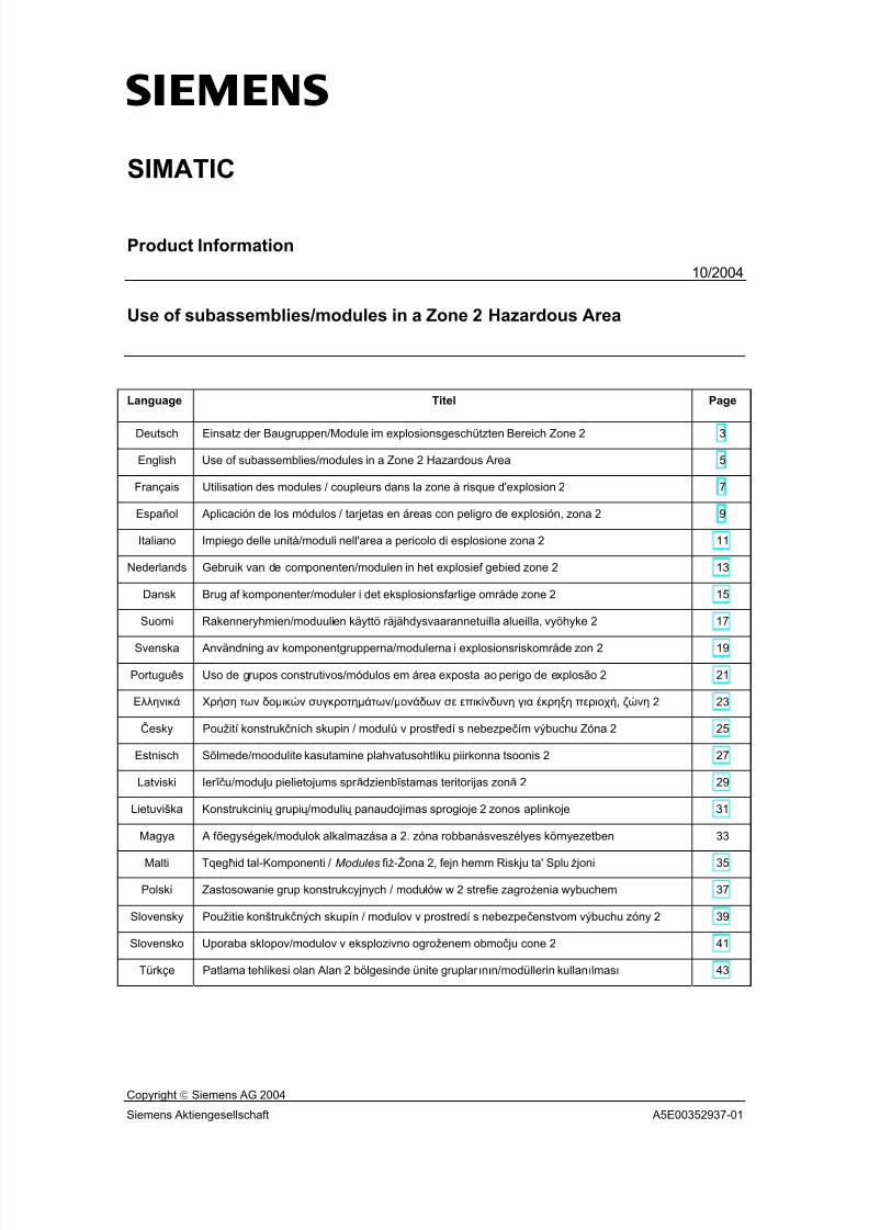
7/31/2019 Diagnose Repeater e
http://slidepdf.com/reader/full/diagnose-repeater-e 161/204
s
Copyright Siemens AG 2004
Siemens Aktiengesellschaft A5E00352937-01
SIMATIC
Product Information
10/2004
Use of subassemblies/modules in a Zone 2 Hazardous Area
Language Titel Page
Deutsch Einsatz der Baugruppen/Module im explosionsgeschützten Bereich Zone 2 3
English Use of subassemblies/modules in a Zone 2 Hazardous Area 5
Français Utilisation des modules / coupleurs dans la zone à risque d'explosion 2 7
Español Aplicación de los módulos / tarjetas en áreas con peligro de explosión, zona 2 9
Italiano Impiego delle unità/moduli nell'area a pericolo di esplosione zona 2 11
Nederlands Gebruik van de componenten/modulen in het explosief gebied zone 2 13
Dansk Brug af komponenter/moduler i det eksplosionsfarlige område zone 2 15
Suomi Rakenneryhmien/moduulien käyttö räjähdysvaarannetuilla alueilla, vyöhyke 2 17
Svenska Användning av komponentgrupperna/modulerna i explosionsriskområde zon 2 19
Português Uso de grupos construtivos/módulos em área exposta ao perigo de explosão 2 21
Ελληνικά Χρήση των δοµικών συγκροτηµάτων/µονάδων σε επικίνδυνη για έκρηξη περιοχή, ζώνη 2 23
Česky Použití konstrukčních skupin / modulů v prostř edí s nebezpečím výbuchu Zóna 2 25
Estnisch Sõlmede/moodulite kasutamine plahvatusohtliku piirkonna tsoonis 2 27
Latviski Ier īču/modu ļu pielietojums spr ādzienb ī stamas teritorijas zonā 2 29
Lietuviška Konstrukcinių grupių /modulių panaudojimas sprogioje 2 zonos aplinkoje 31
Magya A f őegységek/modulok alkalmazása a 2. zóna robbanásveszélyes környezetben 33
Malti Tqegħid tal-Komponenti / Modules fiż-Żona 2, fejn hemm Riskju ta' Spluż joni 35
Polski Zastosowanie grup konstrukcyjnych / modułów w 2 strefie zagrożenia wybuchem 37
Slovensky Použitie konštrukčných skupín / modulov v prostredí s nebezpečenstvom výbuchu zóny 2 39
Slovensko Uporaba sklopov/modulov v eksplozivno ogroženem območ ju cone 2 41
Türkçe Patlama tehlikesi olan Alan 2 bölgesinde ünite gruplar ının/modüllerin kullanılması 43

7/31/2019 Diagnose Repeater e
http://slidepdf.com/reader/full/diagnose-repeater-e 162/204
Product Information on the Use of subassemblies/modules in a Zone 2 Hazardous Area
2 A5E00352937-01

7/31/2019 Diagnose Repeater e
http://slidepdf.com/reader/full/diagnose-repeater-e 163/204
Deutsch
Product Information on the Use of subassemblies/modules in a Zone 2 Hazardous Area 3 A5E00352937-01
Einsatz der Baugruppen/Module im explosions-gefährdeten Bereich Zone 2
Zone 2
Explosionsgefährdete Bereiche werden in Zonen eingeteilt. Die Zonen werdennach der Wahrscheinlichkeit des Vorhandenseins einer explosionsfähigen Atmosphäre unterschieden.
Zone Explosionsgefahr Beispiel
2 explosive Gasatmosphäre trittnur selten und kurzzeitig auf
Bereiche um Flanschverbindungen mitFlachdichtungen bei Rohrleitungen ingeschlossenen Räumen
sicherer Bereich
nein • außerhalb der Zone 2
• Standardanwendungen von dezentraler Peripherie
Nachfolgend finden Sie wichtige Hinweise für die Installation der Baugruppen/Module im explosionsgefährdeten Bereich.
Weitere Informationen
Weitere Informationen zu den Baugruppen/Modulen finden Sie im dazugehörigenHandbuch.
Fertigungsort / Zulassung
II 3 G EEx nA II T3 .. T6 nach EN 50021 : 1999Prüfnummer: siehe Tabelle
Fertigungsort Baugruppen/Module Prüfnummer
ET 200SET 200S Fehlersichere Module
KEMA 01 ATEX 1238X
Siemens AG, Bereich A&DWerner-von-Siemens-Straße 5092224 AmbergGermany
S7-300ET 200MBuskopplung DP/PADiagnoserepeater S7-300 Fehlersichere Baugruppen
KEMA 02 ATEX 1096X
Siemens AG, Bereich A&DÖstliche Rheinbrückenstr. 5076187 KarlsruheGermany
S7-400 KEMA 03 ATEX 1125X
Hinweis
Baugruppen/Module mit der Zulassung II 3 G EEx nA II T3 .. T6 dürfen nur inSIMATIC-Systemen der Gerätekategorie 3 eingesetzt werden.

7/31/2019 Diagnose Repeater e
http://slidepdf.com/reader/full/diagnose-repeater-e 164/204
Deutsch
4 Product Information on the Use of subassemblies/modules in a Zone 2 Hazardous Area A5E00352937-01
Instandhaltung
Für eine Reparatur müssen die betroffene Baugruppen/Module an denFertigungsort geschickt werden. Nur dort darf die Reparatur durchgeführt werden.
Besondere Bedingungen
1. Baugruppen/Module müssen in einen Schaltschrank oder ein metallischesGehäuse eingebaut werden. Diese müssen mindestens die Schutzart IP 54(nach EN 60529) gewährleisten. Dabei sind die Umgebungsbedingungen zuberücksichtigen, in denen das Gerät installiert wird. Für das Gehäuse musseine Herstellererklärung für Zone 2 vorliegen (gemäß EN 50021).
2. Wenn am Kabel bzw. an der Kabeleinführung dieses Gehäuses unter Betriebs-bedingungen eine Temperatur > 70 °C erreicht wird oder wenn unter Betriebs-bedingungen die Temperatur an der Aderverzweigung > 80 °C sein kann,müssen die Temperatureigenschaften der Kabel mit den tatsächlichgemessenen Temperaturen übereinstimmen.
3. Die eingesetzten Kabeleinführungen müssen der geforderten IP-Schutzart und
dem Abschnitt 7.2 (gemäß EN 50021) entsprechen.
4. Alle Geräte, einschließlich Schalter etc., die an den Ein- und Ausgängen vonSIMATIC-Systemen angeschlossen werden, müssen für den ExplosionsschutzTyp EEx nA oder EEx nC genehmigt sein.
5. Es müssen Maßnahmen getroffen werden, dass die Nennspannung durchTransienten um nicht mehr als 40 % überschritten werden kann.
6. Umgebungstemperaturbereich: 0° C bis 60° C
7. Innerhalb des Gehäuses ist an einem nach dem Öffnen gut sichtbaren Platz einSchild mit folgender Warnung anzubringen:
! Warnung
Das Gehäuse darf nur kurze Zeit geöffnet werden, z. B. für visuelle Diagnose.Betätigen Sie dabei keine Schalter, ziehen oder stecken keine Baugruppen undtrennen keine elektrischen Leitungen (Steckverbindungen).Diese Warnung kann unberücksichtigt bleiben, wenn bekannt ist, dass keineexplosionsgefährdete Atmosphäre herrscht.
Liste der zugelassenen Baugruppen/Module
Die Liste mit den zugelassenen Baugruppen/Module finden Sie im Internet:
http://www4.ad.siemens.de/view/cs/
unter der Beitrags-ID 13702947.

7/31/2019 Diagnose Repeater e
http://slidepdf.com/reader/full/diagnose-repeater-e 165/204
English
Product Information on the Use of subassemblies/modules in a Zone 2 Hazardous Area 5 A5E00352937-01
Use of subassemblies/modules in a Zone 2 HazardousArea
Zone 2
Hazardous areas are divided up into zones. The zones are distinguished accordingto the probability of the existence of an explosive atmosphere.
Zone Explosion Hazard Example
2 Explosive gas atmosphereoccurs only seldom and for ashort time
Areas around flange joints with flatgaskets in pipes in enclosed spaces
Safe area No • Outside zone 2
• Standard distributed I/O applications
Below you will find important information on the installation of the
subassemblies/modules in a hazardous area.
Further Information
You will find further information on the subassemblies/modules in thecorresponding manual.
Production Location / Certification
II 3 G EEx nA II T3 .. T6 to EN 50021 : 1999
Test number : see table below
Production Location Subassemblies/Modules Test Number
ET-200SET 200S fault-tolerant modules
KEMA 01 ATEX 1238X
Siemens AG, Bereich A&DWerner-von-Siemens-Straße 5092224 AmbergGermany
S7-300ET-200MDP/PA bus interfaceDiagnostics repeater S7-300 fault-tolerant modules
KEMA 02 ATEX 1096X
Siemens AG, Bereich A&DÖstliche Rheinbrückenstr. 50
76187 KarlsruheGermany
S7-400 KEMA 03 ATEX 1125X
Note
Subassemblies/modules with II 3 G EEx nA II T3 .. T6 certification can only beused in SIMATIC systems rated as category 3 equipment.

7/31/2019 Diagnose Repeater e
http://slidepdf.com/reader/full/diagnose-repeater-e 166/204
English
6 Product Information on the Use of subassemblies/modules in a Zone 2 Hazardous Area A5E00352937-01
Maintenance
If repair is necessary, the affected subassemblies/modules must be sent to the
production location. Repairs can only be carried out there.
Special Conditions
1. Subassemblies/modules must be installed in a cabinet or metal housing. These
must comply with the IP 54 degree of protection as a minimum. The
environmental conditions under which the equipment is installed must be taken
into account. There must be a manufacturer's declaration for zone 2 available
for the housing (in accordance with EN 50021).
2. If a temperature of > 70 °C is reached in the cable or at the cable entry of this
housing under operating conditions, or if a temperature of > 80 °C can be
reached at the junction of the conductors under operating conditions, the
temperature-related properties of the cables must correspond to the
temperatures actually measured.
3. The cable entries used must comply with the required IP degree of protection
and Section 7.2 (in accordance with EN 50021).
4. All devices (including switches, etc.) that are connected to the inputs and
outputs of SIMATIC systems must be approved for EEx nA or EEx nC explosion
protection.
5. Steps must be taken to ensure that the rated voltage through transients cannot
be exceeded by more than 40 %.
6. Ambient temperature range: 0° C to 60° C
7. A sign containing the following warning must be put up inside the housing in an
easily visible position when the housing is opened:
!
Warning The housing can only be opened for a short time (e.g. for visual diagnostics). If you do this, do not operate any switches, remove or install any modules or disconnect any electrical cables (plug-in connections).You can disregard this warning if you know that the atmosphere is not hazardous(i.e. there is no risk of explosion).
List of Approved Subassemblies/Modules
You will find the list of approved subassemblies/modules under the ID 13702947
on the Internet:http://www4.ad.siemens.de/view/cs/.

7/31/2019 Diagnose Repeater e
http://slidepdf.com/reader/full/diagnose-repeater-e 167/204
Français
Product Information on the Use of subassemblies/modules in a Zone 2 Hazardous Area 7 A5E00352937-01
Utilisation des modules / coupleurs dans la zone àrisque d'explosion 2
Zone 2
Les environnements à risque d'explosion sont répartis en zones. Les zones sedistinguent par la probabilité de présence d'une atmosphère explosive.
Zone Risque d'explosion Exemple
2 Formation rare et brève d'uneatmosphère gazeuse explosive
Environnement de raccords à joints platsdans le cas de conduites dans des locauxfermés
Zone sûre Non • A l'extérieur de la zone 2
• Utilisation standard de périphériedécentralisée
Vous trouverez ci-après des remarques importantes pour l'installation de la stationde périphérie décentralisée des modules / coupleurs dans la zone à risqued'explosion.
Informations complémentaires
Des informations complémentaires sur les modules / cartouches se trouvent dansle manuel correspondant.
Lieu de fabrication / Homologation
II 3 G EEx nA II T3 .. T6 selon EN 50021 : 1999Numéro de contrôle : voir tableau
Lieu de fabrication Modules / coupleurs Numéro decontrôle
ET 200SModules à sécurité intrinsèqueET 200S
KEMA 01 ATEX 1238X
Siemens AG, Bereich A&DWerner-von-Siemens-Straße 5092224 AmbergGermany S7-300
ET 200MCouplage de bus DP/PARépéteur de diagnosticModules à sécurité intrinsèqueS7-300
KEMA 02 ATEX 1096X
Siemens AG, Bereich A&DÖstliche Rheinbrückenstr. 5076187 KarlsruheGermany
S7-400 KEMA 03 ATEX 1125X
Nota
Les modules / coupleurs homologués II 3 G EEx nA II T3 .. T6 ne peuventêtre utilisés que dans des systèmes SIMATIC de catégorie 3.

7/31/2019 Diagnose Repeater e
http://slidepdf.com/reader/full/diagnose-repeater-e 168/204
Français
8 Product Information on the Use of subassemblies/modules in a Zone 2 Hazardous Area A5E00352937-01
Entretien
Si une réparation est nécessaire, le module / coupleur concerné doit être expédié
au lieu de production. La réparation ne doit être effectuée qu'en ce lieu.
Conditions particulières
1. Les modules / coupleurs doivent être installés dans une armoire ou un boîtier
métallique. Ceux-ci doivent assurer au moins l'indice de protection IP 54. Il faut
alors tenir compte des conditions d'environnement dans lesquelles l'appareil est
installé. Le boîtier doit faire l’objet d’une déclaration de conformité du fabricant
pour la zone 2 (selon EN 50021).
2. Si dans les conditions d’exploitation, une température > 70 °C est atteinte au
niveau du câble ou de l’entrée du câble dans ce boîtier, ou bien si la
température au niveau de la dérivation des conducteurs peut être > 80 °C, les
capacités de résistance thermique des câbles doivent corespondre aux
températures effectivement mesurées.
3. Les entrées de câbles utilisées doivent avoir le niveau de protection IP exigé et
être conformes au paragraphe 7.2 (selon EN 50021).
4. Tous les appareillages (y compris les interrupteurs, etc.) raccordés aux entrées
et sorties de systèmes SIMATIC doivent être homologués pour la protection
antidéflagrante type EEx nA ou EEx nC.
5. Il faut prendre des mesures pour que la tension nominale ne puisse pas être
dépassée de plus de 40% sous l’influence de transitoires.
6. Plage de température ambiante : 0° C à 60° C
7. A l’intérieur du boîtier, il faut placer, à un endroit bien visible après ouverture,
une plaquette comportant l’avertissement suivant :
!
AvertissementOuvir le boîtier le moins longtemps possible, par exemple pour effectuer undiagnostic visuel. Ce faisant, n’actionnez aucun commutateur, ne déconnectezaucun module et ne débanchez pas de câbles électriques (connexions).Le respect de cet avertissement n’est pas impératif s’il est certain quel’environnement ne présente pas de risque d’explosion.
Liste des modules / coupleurs homologués
Vous trouverez sur Internet la liste des modules / coupleurs homologués :
http://www4.ad.siemens.de/view/cs/
référence ID 13702947.

7/31/2019 Diagnose Repeater e
http://slidepdf.com/reader/full/diagnose-repeater-e 169/204
Español
Product Information on the Use of subassemblies/modules in a Zone 2 Hazardous Area 9 A5E00352937-01
Aplicación de los módulos / tarjetas en áreas conpeligro de explosión, zona 2
Zona 2
Las áreas con peligro de explosión se clasifican en zonas. Las zonas sediferencian según la probabilidad de la existencia de una atmósfera capaz de sufrir una explosión.
Zona Peligro de explosión Ejemplo
2 La atmósfera explosiva de gassólo se presenta rara vez y muybrevemente
Áreas alrededor de uniones abridadas con juntasplanas en tuberías en locales cerrados
Área segura no • fuera de la zona 2
• Aplicaciones estándar de la periferiadescentralizada
A continuación encontrará importantes informaciones para la instalación de losmódulos / tarjetas en áreas con peligro de explosión.
Otras informaciones
Encontrará otras informaciones relativas a los módulos / tarjetas en el Manualcorrespondiente.
Lugar de fabricación / Homologación
II 3 G EEx nA II T3 .. T6 según norma EN 50021 : 1999Número de comprobación: véase tabla
Lugar de fabricación Módulos / tarjetas Número de
comprobación
ET 200SGrupos ET 200S a prueba de fallos
KEMA 01 ATEX 1238 X
Siemens AG, Bereich A&DWerner-von-Siemens-Straße 5092224 AmbergGermany
S7-300ET 200M Acoplamiento de bus DP/PA
Repetidor de diagnósticoGrupos S7-300 a prueba de fallos
KEMA 02 ATEX 1096 X
Siemens AG, Bereich A&DÖstliche Rheinbrückenstr.50 76187 KarlsruheGermany
S7-400 KEMA 03 ATEX 1125 X
Nota
Los módulos / tarjetas con la homologación II 3 G EEx nA II T3 .. T6 puedenutilizarse únicamente en los sistemas SIMATIC de la categoría de equipo 3.
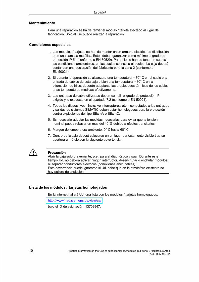
7/31/2019 Diagnose Repeater e
http://slidepdf.com/reader/full/diagnose-repeater-e 170/204
Español
10 Product Information on the Use of subassemblies/modules in a Zone 2 Hazardous Area A5E00352937-01
Mantenimiento
Para una reparación se ha de remitir el módulo / tarjeta afectado al lugar defabricación. Sólo allí se puede realizar la reparación.
Condiciones especiales
1. Los módulos / tarjetas se han de montar en un armario eléctrico de distribucióno en una carcasa metálica. Éstos deben garantizar como mínimo el grado deprotección IP 54 (conforme a EN 60529). Para ello se han de tener en cuentalas condiciones ambientales, en las cuales se instala el equipo. La caja deberácontar con una declaración del fabricante para la zona 2 (conforme aEN 50021).
2. Si durante la operación se alcanzara una temperatura > 70° C en el cable o laentrada de cables de esta caja o bien una temperatura > 80° C en labifurcación de hilos, deberán adaptarse las propiedades térmicas de los cablesa las temperaturas medidas efectivamente.
3. Las entradas de cable utilizadas deben cumplir el grado de protección IP
exigido y lo expuesto en el apartado 7.2 (conforme a EN 50021).
4. Todos los dispositivos –inclusive interruptores, etc.– conectados a las entradasy salidas de sistemas SIMATIC deben estar homologados para la proteccióncontra explosiones del tipo EEx nA o EEx nC.
5. Es necesario adoptar las medidas necesarias para evitar que la tensiónnominal pueda rebasar en más del 40 % debido a efectos transitorios.
6. Margen de temperatura ambiente: 0° C hasta 60° C
7. Dentro de la caja deberá colocarse en un lugar perfectamente visible tras suapertura un rótulo con la siguiente advertencia:
! Precaución Abrir la caja sólo brevemente, p.ej. para el diagnóstico visual. Durante estetiempo Ud. no deberá activar ningún interruptor, desenchufar o enchufar módulosni separar conductores eléctricos (conexiones enchufables).Esta advertencia puede ignorarse si Ud. sabe que en la atmósfera existente nohay peligro de explosión.
Lista de los módulos / tarjetas homologados
En la internet hallará Ud. una lista con los módulos / tarjetas homologados:
http://www4.ad.siemens.de/view/cs/
bajo el ID de asignación 13702947.
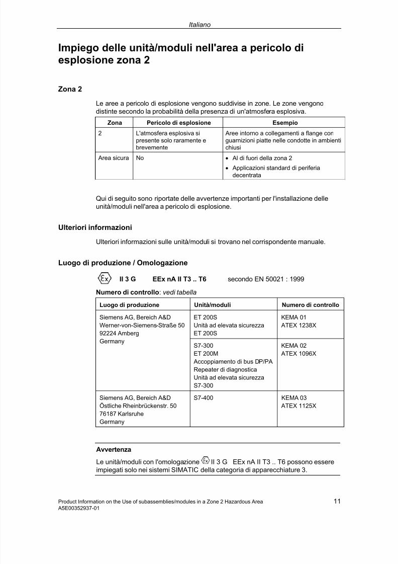
7/31/2019 Diagnose Repeater e
http://slidepdf.com/reader/full/diagnose-repeater-e 171/204
Italiano
Product Information on the Use of subassemblies/modules in a Zone 2 Hazardous Area 11 A5E00352937-01
Impiego delle unità/moduli nell'area a pericolo diesplosione zona 2
Zona 2
Le aree a pericolo di esplosione vengono suddivise in zone. Le zone vengonodistinte secondo la probabilità della presenza di un'atmosfera esplosiva.
Zona Pericolo di esplosione Esempio
2 L'atmosfera esplosiva sipresente solo raramente ebrevemente
Aree intorno a collegamenti a flange conguarnizioni piatte nelle condotte in ambientichiusi
Area sicura No • Al di fuori della zona 2
• Applicazioni standard di periferiadecentrata
Qui di seguito sono riportate delle avvertenze importanti per l'installazione delleunità/moduli nell'area a pericolo di esplosione.
Ulteriori informazioni
Ulteriori informazioni sulle unità/moduli si trovano nel corrispondente manuale.
Luogo di produzione / Omologazione
II 3 G EEx nA II T3 .. T6 secondo EN 50021 : 1999
Numero di controllo: vedi tabella
Luogo di produzione Unità/moduli Numero di controllo
ET 200SUnità ad elevata sicurezzaET 200S
KEMA 01 ATEX 1238X
Siemens AG, Bereich A&DWerner-von-Siemens-Straße 5092224 AmbergGermany
S7-300ET 200M Accoppiamento di bus DP/PARepeater di diagnosticaUnità ad elevata sicurezzaS7-300
KEMA 02 ATEX 1096X
Siemens AG, Bereich A&DÖstliche Rheinbrückenstr. 5076187 KarlsruheGermany
S7-400 KEMA 03 ATEX 1125X
Avvertenza
Le unità/moduli con l'omologazione II 3 G EEx nA II T3 .. T6 possono essereimpiegati solo nei sistemi SIMATIC della categoria di apparecchiature 3.
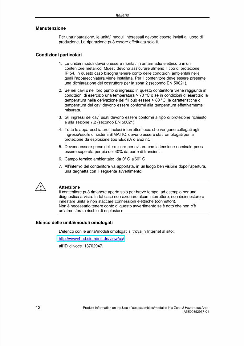
7/31/2019 Diagnose Repeater e
http://slidepdf.com/reader/full/diagnose-repeater-e 172/204
Italiano
12 Product Information on the Use of subassemblies/modules in a Zone 2 Hazardous Area A5E00352937-01
Manutenzione
Per una riparazione, le unità/i moduli interessati devono essere inviati al luogo di
produzione. La riparazione può essere effettuata solo lì.
Condizioni particolari
1. Le unità/i moduli devono essere montati in un armadio elettrico o in un
contenitore metallico. Questi devono assicurare almeno il tipo di protezione
IP 54. In questo caso bisogna tenere conto delle condizioni ambientali nelle
quali l'apparecchiatura viene installata. Per il contenitore deve essere presente
una dichiarazione del costruttore per la zona 2 (secondo EN 50021).
2. Se nei cavi o nel loro punto di ingresso in questo contenitore viene raggiunta in
condizioni di esercizio una temperatura > 70 °C o se in condizioni di esercizio la
temperatura nella derivazione dei fili può essere > 80 °C, le caratteristiche di
temperatura dei cavi devono essere conformi alla temperatura effettivamente
misurata.
3. Gli ingressi dei cavi usati devono essere conformi al tipo di protezione richiesto
e alla sezione 7.2 (secondo EN 50021).
4. Tutte le apparecchiature, inclusi interruttori, ecc. che vengono collegati agli
ingressi/uscite di sistemi SIMATIC, devono essere stati omologati per la
protezione da esplosione tipo EEx nA o EEx nC.
5. Devono essere prese delle misure per evitare che la tensione nominale possa
essere superata per più del 40% da parte di transienti.
6. Campo termico ambientale: da 0° C a 60° C
7. All’interno del contenitore va apportata, in un luogo ben visibile dopo l’apertura,
una targhetta con il seguente avvertimento:
! AttenzioneIl contenitore può rimanere aperto solo per breve tempo, ad esempio per unadiagnostica a vista. In tal caso non azionare alcun interruttore, non disinnestare oinnestare unità e non staccare connessioni elettriche (connettori).Non è necessario tenere conto di questo avvertimento se è noto che non c’èun’atmosfera a rischio di esplosione
Elenco delle unità/moduli omologati
L'elenco con le unità/moduli omologati si trova in Internet al sito:
http://www4.ad.siemens.de/view/cs/
all’ID di voce 13702947.

7/31/2019 Diagnose Repeater e
http://slidepdf.com/reader/full/diagnose-repeater-e 173/204
Nederlands
Product Information on the Use of subassemblies/modules in a Zone 2 Hazardous Area 13 A5E00352937-01
Gebruik van de componenten/modulen in het explosief gebied zone 2
Zone 2
Explosieve gebieden worden ingedeeld in zones. Bij de zones wordtonderscheiden volgens de waarschijnlijkheid van de aanwezigheid van eenexplosieve atmosfeer.
Zone Explosiegevaar Voorbeeld
2 Een explosieve gasatmosfeer treedt maar zelden op en voor korte duur
Gebieden rond flensverbindingen metpakkingen bij buisleidingen in geslotenvertrekken
Veiliggebied
neen • Buiten de zone 2
• Standaardtoepassingen van decentraleperiferie
Hierna vindt u belangrijke aanwijzingen voor de installatie van decomponenten/modulen in het explosief gebied.
Verdere informatie
In het bijhorende handboek vindt u verdere informatie over decomponenten/modulen
Productieplaats / Vergunning
II 3 G EEx nA II T3 .. T6 conform EN 50021 : 1999
Keuringsnummer: zie tabel
Productieplaats Componenten/modulen Keuringsnummer
ET 200SET 200S tegen foutenbeveiligde componenten
KEMA 01 ATEX 1238XSiemens AG, Bereich A&DWerner-von-Siemens-Strasse 5092224 AmbergGermany
S7-300ET 200 MBuskoppeling DP/PADiagnoserepeater
S7-300 tegen fouten beveiligdecomponenten
KEMA 02 ATEX 1096X
Siemens AG, Bereich A&DÖstliche Rheinbrückenstr. 5076187 KarlsruheGermany
S7-400 KEMA 03 ATEX 1125X
Opmerking
Componenten/modulen met de vergunning II 3 G EEx nA II T3 .. T6 mogenslechts worden gebruikt in SIMATIC-systemen van de apparaatcategorie 3.

7/31/2019 Diagnose Repeater e
http://slidepdf.com/reader/full/diagnose-repeater-e 174/204
Nederlands
14 Product Information on the Use of subassemblies/modules in a Zone 2 Hazardous Area A5E00352937-01
Instandhouding
Voor een reparatie moeten de betreffende componenten/modulen naar de plaatsvan vervaardiging worden gestuurd. Alleen daar mag de reparatie wordenuitgevoerd.
Speciale voorwaarden
1. Componenten/modulen moeten worden ingebouwd in een schakelkast of in eenbehuizing van metaal. Deze moeten minstens de veiligheidsgraad IP 54waarborgen. Hierbij dient rekening te worden gehouden met deomgevingsvoorwaarden waarin het apparaat wordt geïnstalleerd. Voor debehuizing dient een verklaring van de fabrikant voor zone 2 te wordeningediend (volgens EN 50021).
2. Als aan de kabel of aan de kabelinvoering van deze behuizing onder bedrijfsomstandigheden een temperatuur wordt bereikt > 70 °C of als onder bedrijfsomstandigheden de temperatuur aan de adervertakking > 80 °C kanzijn, moeten de temperatuureigenschappen van de kabel overeenstemmen met
de werkelijk gemeten temperaturen.3. De aangebrachte kabelinvoeringen moeten de vereiste IP-veiligheidsgraad
hebben en in overeenstemming zijn met alinea 7.2 (volgens EN 50021).
4. Alle apparaten, schakelaars enz. inbegrepen, die worden aangesloten op de in-en uitgangen van SIMATIC-systemen, moeten zijn goedgekeurd voor deexplosiebeveiliging type EEx nA of EEx nC.
5. Er dienen maatregelen te worden getroffen, zodat de nominale spanning door transiënten met niet meer dan 40 % kan worden overschreden.
6. Omgevingstemperatuurbereik: 0° C tot 60° C
7. Binnen de behuizing dient op een na het openen goed zichtbare plaats een
bord te worden aangebracht met de volgende waarschuwing:
! WaarschuwingDe behuizing mag slechts voor korte tijd worden geopend, bijv. voor een visuelediagnose. Bedien hierbij geen schakelaar, trek of steek geen modulen enontkoppel geen elektrische leidingen (steekverbindingen).Deze waarschuwing kan buiten beschouwing blijven, indien bekend is dat er geen explosieve atmosfeer heerst.
Lijst van de toegelaten componenten/modulen
De lijst met de toegelaten componenten/modulen vindt u in het internet:
http://www4.ad.siemens.de/view/cs/
onder de bijdrage-ID 13702947.

7/31/2019 Diagnose Repeater e
http://slidepdf.com/reader/full/diagnose-repeater-e 175/204
Dansk
Product Information on the Use of subassemblies/modules in a Zone 2 Hazardous Area 15 A5E00352937-01
Brug af komponenter/moduler i det eksplosionsfarligeområde zone 2
Zone 2
Eksplosionsfarlige områder inddeles i zoner. Zonerne adskiller sig indbyrdes efter hvor sandsynligt det er, at der er en eksplosiv atmosfære.
Zone Eksplosionsfare Eksempel
2 Eksplosiv gasatmosfæreoptræder kun sjældent og varer kort
Områder rundt om flangeforbindelser medflade pakninger ved rørledninger i lukkederum
Sikkertområde
Nej • Uden for zone 2
• Standardanvendelser decentral periferi
I det følgende findes vigtige henvisninger vedr. installation af komponenter/moduler
i det eksplosionsfarlige område.
Yderligere informationer
Yderligere informationer om komponenterne/modulerne findes i den pågældendemanual.
Produktionssted / Godkendelse
II 3 G EEx nA II T3 .. T6 efter EN 50021 : 1999
Kontrolnummer: se tabel
Produktionssted Komponenter/moduler Kontrolnummer
ET 200SET 200S fejlsikrekomponenter
KEMA 01 ATEX 1238X
KEMA 02 ATEX 1096X
Siemens AG, Bereich A&DWerner-von-Siemens-Straße 5092224 AmbergGermany S7-300
ET 200MBuskobling DP/PADiagnoserepeater S7-300 fejlsikre komponenter
Siemens AG, Bereich A&DÖstliche Rheinbrückenstr. 50
76187 KarlsruheGermany
S7-400 KEMA 03 ATEX 1125X
Bemærk
Komponenter/moduler med godkendelsen II 3 G EEx nA II T3 .. T6 må kunmonteres i SIMATIC-systemer for udstyrskategori 3.

7/31/2019 Diagnose Repeater e
http://slidepdf.com/reader/full/diagnose-repeater-e 176/204
Dansk
16 Product Information on the Use of subassemblies/modules in a Zone 2 Hazardous Area
A5E00352937-01
Vedligeholdelse
Hvis de pågældende komponenter/moduler skal repareres, bedes De sende demtil produktionsstedet. Reparation må kun udføres der.
Særlige betingelser
1. Komponenterne/modulerne skal monteres i et kontrolskab eller et metalkabinet.Disse skal mindst kunne sikre beskyttelsesklasse IP 54. I denne forbindelseskal der tages højde for de omgivelsestemperaturer, i hvilke udstyret er installeret. Der skal være udarbejdet en erklæring fra fabrikanten for kabinettetfor zone 2 (iht. EN 50021).
2. Hvis kablet eller kabelindføringen på dette hus når op på en temperatur på> 70 °C under driftsbetingelser eller hvis temperaturen på åreforegreningen kanvære > 80 °C under driftsbetingelser, skal kablernes temperaturegenskaber stemme overens med de temperaturer, der rent faktisk måles.
3. De benyttede kabelindføringer skal være i overensstemmelse med denkrævede IP-beskyttelsestype og afsnittet 7.2 (iht. EN 50021).
4. Alle apparater, inkl. kontakter osv., der forbindes med ind- og udgangene tilSIMATIC-systemerne, skal være godkendt til eksplosionsbeskyttelse af type EEx nA eller EEx nC.
5. Der skal træffes foranstaltninger, der sørger for, at den nominelle spænding viatransienter ikke kan overskrides mere end 40 %.
6. Omgivelsestemperaturområde: 0° C til 60° C
7. I kabinettet skal der anbringes et skilt, der skal kunne ses, når kabinettet åbnes.Dette skilt skal have følgende advarsel:
! AdvarselKabinettet må kun åbnes i kort tid, f.eks. til visuel diagnose. Tryk i denneforbindelse ikke på kontakter, træk eller isæt ikke komponenter og afbryd ikkeelektriske ledninger (stikforbindelser).Der skal ikke tages højde for denne advarsel, hvis man ved, at der ikke er nogeneksplosionsfarlig atmosfære.
Liste over godkendte komponenter/moduler
Listen med de godkendte komponenter/moduler findes på internettet:
http://www4.ad.siemens.de/view/cs/
under bidrags-ID 13702947.

7/31/2019 Diagnose Repeater e
http://slidepdf.com/reader/full/diagnose-repeater-e 177/204
Suomi
Product Information on the Use of subassemblies/modules in a Zone 2 Hazardous Area 17 A5E00352937-01
Rakenneryhmien/moduulien käyttöräjähdysvaarannetuilla alueilla, vyöhyke 2
Vyöhyke 2
Räjähdysvaarannetut alueet jaetaan vyöhykkeisiin. Vyöhykkeet erotellaanräjähdyskelpoisen ilmakehän olemassa olon todennäköisyyden mukaan.
Vyöhyke Räjähdysvaara Esimerkki
2 Räjähtävä kaasuilmakehäilmaantuu vain harvoin jalyhytaikaisesti
Alueet putkistojen lattatiivisteillä varustuillalaippaliitoksilla suljetuissa tiloissa
turvallinenalue
ei • vyöhykkeen 2 ulkopuolella
• Hajautetun ulkopiirin vakiosovellukset
Seuraavasta löydätte tärkeitä ohjeita rakenneryhmien/moduulien asennukseen
räjähdysvaarannetuilla alueilla.
Lisätietoja
Lisätietoja rakenneryhmiin/moduuleihin löydätte niihin kuuluvista ohjekirjasta.
Valmistuspaikka / Hyväksyntä
II 3 G EEx nA II T3 .. T6 EN 50021 mukaan: 1999
Tarkastusnumero: katso taulukko Valmistuspaikka Rakenneryhmät/moduulit Tarkastusnumero
Siemens AG, Bereich A&DWerner-von-Siemens-Straße 5092224 AmbergGermany
ET 200SET 200S läpi-iskuvarmatrakenneryhmät
S7-300ET 200MVäyläkytkin DP/PADignoositoistinS7-300 läpi-iskuvarmatrakenneryhmät
KEMA 01 ATEX 1238X
KEMA 02 ATEX 1096X
Siemens AG, Bereich A&D
Östliche Rheinbrückenstr. 5076187 KarlsruheGermany
S7-400 KEMA 03 ATEX 1125X
Ohje
Rakenneryhmät/moduulit hyväksynnän II 3 G EEx nA II T3 .. T6 kanssasaadaan käyttää ainoastaan laitekategorian 3 SIMATIC-järjestelmissä.

7/31/2019 Diagnose Repeater e
http://slidepdf.com/reader/full/diagnose-repeater-e 178/204
Suomi
18 Product Information on the Use of subassemblies/modules in a Zone 2 Hazardous Area A5E00352937-01
Kunnossapito
Korjausta varten täytyy kyseinen rakenneryhmä/moduuli lähettäävalmistuspaikkaan. Korjaus voidaan suorittaa ainoastaan siellä.
Erityiset vaatimukset
1. Rakenneryhmät/moduulit täytyy asentaa kytkentäkaappiin tai metalliseenkoteloon. Näiden täytyy olla vähintään kotelointiluokan IP 54 mukaisia. Tällöinon huomioitava ympäristöolosuhteet, johon laite asennetaan. Kotelolle täytyyolla valmistajaselvitys vyöhykettä 2 varten (EN 50021 mukaan).
2. Kun johdolla tai tämän kotelon johdon sisäänviennillä saavutetaan > 70 °Clämpötila tai kun käyttöolosuhteissa lämpötila voi piuhajaotuksella olla > 80 °C,täytyy johdon lämpötilaominaisuuksien vastata todellisesti mitattuja lämpötiloja.
3. Käytettyjen johtojen sisäänohjauksien täytyy olla vaaditun IP-kotelointiluokan jakohdan 7.2 (EN 50021 mukaan) mukaisia.
4. Kaikkien laitteiden, kytkimet jne. mukaan lukien, jotka liitetään SIMATIC-
järjestelmien tuloille ja lähdöille, täytyy olla hyväksyttyjä tyypin EEx nA taiEEx nC räjähdyssuojausta varten.
5. Toimenpiteet täytyy suorittaa, ettei nimellisjännite voi transienttien kautta ylittyäenemmän kuin 40 %.
6. Ympäristölämpötila-alue: 0° C ... 60° C
7. Kotelon sisälle, avauksen jälkeen näkyvälle paikalle, on kiinnitettävä kilpi, jossaon seuraava varoitus:
! VaroitusKotelo saadaan avata ainoastaan lyhyeksi ajaksi, esim. visuaalista diagnoosia
varten. Älä tällöin käytä mitään kytkimiä, vedä tai liitä mitään rakenneryhmiä,äläkä erota mitään sähköjohtoja (pistoliittimiä).Tätä varoitusta ei tarvitse huomioida, kun on tiedossa, että minkäänlaistaräjähdysvaarannettua ilmakehää ei ole olemassa.
Hyväksyttyjen rakenneryhmien/moduulien lista
Lista hyväksytyistä rakennesarjoista/moduuleista löytyy internetistä osoitteesta:
http://www4.ad.siemens.de/view/cs/
käyttäjätunnuksella 13702947.

7/31/2019 Diagnose Repeater e
http://slidepdf.com/reader/full/diagnose-repeater-e 179/204
Svenska
Product Information on the Use of subassemblies/modules in a Zone 2 Hazardous Area 19 A5E00352937-01
Användning av komponentgrupperna/modulerna iexplosionsriskområde zon 2
Zon 2
Explosionsriskområden delas in i zoner. Zonerna delas in enligt sannolikheten atten atmosfär med explosionsfara föreligger.
Zon Explosionsfara Exempel
2 Explosiv gasatmosfär uppstår endast sällan eller kortvarigt
Områden kring flänsförbindelser medpackningar vid rörledningar i slutnautrymmen
Säkertområde
Nej • Utanför zon 2
• Standardanvändning av decentralperiferi
Nedan följer viktiga anvisningar om installationen avkomponentgrupperna/modulerna i ett explosionsriskområde.
Ytterligare information
Ytterligare information om komponentgrupperna/modulerna finner du i tillhörandehandbok.
Tillverkningsort / Godkännande
II 3 G EEx nA II T3 .. T6 enligt EN 50021 : 1999
Kontrollnummer: se tabell
Tillverkningsort Komponentgrupper/
moduler
Kontrollnummer
ET 200SET 200S Felsäkrakomponentgrupper
KEMA 01 ATEX 1238XSiemens AG, Bereich A&DWerner-von-Siemens-Straße 5092224 AmbergGermany
S7-300ET 200MBusskoppling DP/PADiagnosrepeater S7-300 Felsäkra
komponentgrupper
KEMA 02 ATEX 1096X
Siemens AG, Bereich A&DÖstliche Rheinbrückenstr. 5076187 KarlsruheGermany
S7-400 KEMA 03 ATEX 1125X
Anvisning
Komponentgrupper/moduler med godkännande II 3 G EEx nA II T3 .. T6 får endast användas i SIMATIC-system i apparatgrupp 3.
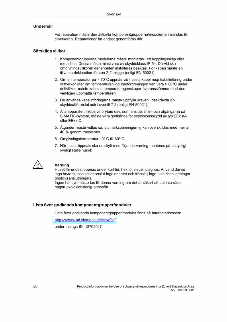
7/31/2019 Diagnose Repeater e
http://slidepdf.com/reader/full/diagnose-repeater-e 180/204
Svenska
20 Product Information on the Use of subassemblies/modules in a Zone 2 Hazardous Area A5E00352937-01
Underhåll
Vid reparation måste den aktuella komponentgrupperna/modulerna insändas tilltillverkaren. Reparationer får endast genomföras där.
Särskilda villkor
1. Komponentgrupperna/modulerna måste monteras i ett kopplingsskåp eller metallhus. Dessa måste minst vara av skyddsklass IP 54. Därvid skaomgivningsvillkoren där enheten installeras beaktas. För kåpan måste entillverkardeklaration för zon 2 föreligga (enligt EN 50021).
2. Om en temperatur på > 70°C uppnås vid husets kabel resp kabelinföring under driftvillkor eller om temperaturen vid trådförgreningen kan vara > 80°C under driftvillkor, måste kabelns temperaturegenskaper överensstämma med denverkligen uppmätta temperaturen.
3. De använda kabelinföringarna måste uppfylla kraven i det krävda IP-skyddsutförandet och i avsnitt 7.2 (enligt EN 50021).
4. Alla apparater, inklusive brytare osv, som ansluts till in- och utgångarna påSIMATIC-system, måste vara godkända för explosionsskydd av typ EEx nAeller EEx nC.
5. Åtgärder måste vidtas så, att märkspänningen ej kan överskridas med mer än40 % genom transienter.
6. Omgivningstemperatur: 0° C till 60° C
7. När huset öppnats ska en skylt med följande varning monteras på ett tydligtsynligt ställe huset:
!
Varning
Huset får endast öppnas under kort tid, t ex för visuell diagnos. Använd därvidinga brytare, lossa eller anslut inga enheter och frånskilj inga elektriska ledningar (insticksanslutningar).Ingen hänsyn måste tas till denna varning om det är säkert att det inte råder någon explosionsfarlig atmosfär.
Lista över godkända komponentgrupper/moduler
Lista över godkända komponentgrupper/moduler finns på Internetadressen:
http://www4.ad.siemens.de/view/cs/
under bidrags-ID 13702947.

7/31/2019 Diagnose Repeater e
http://slidepdf.com/reader/full/diagnose-repeater-e 181/204
Português
Product Information on the Use of subassemblies/modules in a Zone 2 Hazardous Area 21 A5E00352937-01
Uso de grupos construtivos/módulos em área expostaao perigo de explosão 2
Zona 2
As áreas expostas ao perigo de explosão são divididas em zonas. As zonas sãodiferenciadas de acordo com a probabilidade da existência de uma atmosferaexplosiva.
Zona Perigo de explosão Exemplo
2 Só raramente e por um breveperíodo de tempo surgematmosferas explosivas
Áreas em torno de ligações flangeadascom vedações chatas em tubulações emrecintos fechados
Área segura não • fora da zona 2
• Aplicações descentralizadas deperiferia descentralizada
A seguir, o encontrará avisos importantes para a instalação de gruposconstrutivos/ módulos em área exposta ao perigo de explosão.
Mais informações
Para obter mais informações sobre grupos construtivos/módulos, consulte orespectivo manual.
Local de produção / Licença
II 3 G EEx nA II T3 .. T6 seg. EN 50021 : 1999Número de ensaio: veja a tabela
Local de produção Grupos
construtivos/módulos
N° de ensaio
ET 200SET 200S Grupos construtivosprotegidos contra erro
KEMA 01 ATEX 1238X
Siemens AG, Bereich A&DWerner-von-Siemens-Straße 5092224 Amberg Alemanha S7-300
ET 200M Acoplador bus DP/PA
Repetidor de diagnósticoS7-300 Grupos construtivosprotegidos contra erro
KEMA 02 ATEX 1096X
Siemens AG, Bereich A&DÖstliche Rheinbrückenstr. 5076187 Karlsruhe Alemanha
S7-400 KEMA 03 ATEX 1125X

7/31/2019 Diagnose Repeater e
http://slidepdf.com/reader/full/diagnose-repeater-e 182/204
Português
22 Product Information on the Use of subassemblies/modules in a Zone 2 Hazardous Area A5E00352937-01
Aviso
Os grupos construtivos/módulos com a licença II 3 G EEx nA II T3 .. T6 sópodem ser aplicados em sistemas SIMATIC da categoria de aparelho 3.
ReparoOs grupos construtivos/módulos em questão devem ser remetidos para o local deprodução a fim de que seja realizado o reparo. Apenas lá deve ser efetuado oreparo.
Condições especiais
1. Os grupos construtivos/módulos devem ser montados em um armário dedistribuição ou em uma caixa metálica. Estes devem garantir no mínimo o tipode protecção IP 54. Durante este trabalho deverão ser levados emconsideração as condições locais, nas quais o aparelho será instalado. Para acaixa deverá ser apresentada uma declaração do fabricante para a zona 2 (deacordo com EN 50021).
2. Caso no cabo ou na entrada do cabo desta carcaça sob as condiçõesoperacionais seja atingida uma temperatura de > 70 °C, ou caso sob condiçõesoperacionais a temperatura na ramificação do fio poderá atingir > 80 °C, ascaraterísticas de temperatura deverão corresponder às temperaturas realmentemedidas.
3. As entradas de cabo utilizadas devem corresponder ao tipo exigido deprotecção IP e à seção 7.2 (de acordo com o EN 50021).
4. Todos os aparelhos, inclusive as chaves, etc., que estejam conectadas ementradas e saídas dos sistemas SIMATIC devem possuir a licença para aprotecção de explosão do tipo EEx nA ou EEx nC.
5. Precisam ser tomadas medidas para que a tensão nominal através detransitórios não possa ser ultrapassada em mais que 40 %.
6. Área de temperatura ambiente: 0° C até 60° C
7. No âmbito da carcaça deve ser colocada, após a abertura, em um ponto bemvisível uma placa com a seguinte advertência:
! Advertência A carcaça deve ser aberta apenas por um breve período de tempo, por ex. paradiagnóstico visual. Não acione nenhum interruptor, não retire ou conecte nenhum
módulo e não separe nenhum fio elétrico (ligações de tomada).Esta advertência poderá ser ignorada caso se saiba que não há nenhumaatmosfera sujeita ao perigo de explosão.
Lista dos grupos construtivos/módulos autorizados
A lista com os grupos construtivos/módulos autorizados encontram-se na Internet:
http://www4.ad.siemens.de/view/cs/
sob o número de ID 13702947.

7/31/2019 Diagnose Repeater e
http://slidepdf.com/reader/full/diagnose-repeater-e 183/204
Ελληνικά
Product Information on the Use of subassemblies/modules in a Zone 2 Hazardous Area 23 A5E00352937-01
Χρήση των δοµικών συγκροτηµάτων /µονάδων σε επικίνδυνη για έκρηξη περιοχή, ζώνη 2
Ζώνη 2
Οι επικίνδυνες για έκρηξη περιοχές χωρίζονται σε ζώνες. Οι ζώνες διαφέρουν σύµφωνα µε την πιθανότητα ύπαρξης ενός ικανού για έκρηξη περιβάλλοντος.
Ζώνη Κίνδυνος έκρηξης Παράδειγµα
2 Εκρηκτικό περιβάλλον αερίου παρουσιάζεται µόνο σπάνια και για σύντοµο χρονικό διάστηµα
Περιοχές γύρω από φλαντζωτές συνδέσεις µε τσιµούχες σε σωληνώσεις σε κλειστούς χώρους
Ασφαλής περιοχή
όχι • Εκτός της ζώνης 2
• Τυπικές εφαρµογές αποκεντρωµένης περιφέρειας
Στη συνέχεια θα βρείτε σηµαντικές υποδείξεις για την εγκατάσταση των δοµικών συγκροτηµάτων/µονάδων σε επικίνδυνη για έκρηξη περιοχή.
Επιπλέον πληροφορίες
Επιπλέον πληροφορίες για τα δοµικά συγκροτήµατα/µονάδες θα βρείτε στο αντίστοιχο εγχειρίδιο.
Τόπος κατασκευής / Άδεια
II 3 G EEx nA II T3 .. T6 σύµφωνα µε το πρότυπο
EN 50021 : 1999
Αριθµός ελέγχου: βλέπε πίνακα
Τόπος κατασκευής ∆οµικά συγκροτήµατα /µονάδες Αιθµ. ελέγχου
ET 200S
ET 200S Ασφαλή σε περίπτωση
βλάβης δοµικά συγκροτήµατα
KEMA 01
ATEX 1238X
Siemens AG, Bereich A&DWerner-von-Siemens-Straße 5092224 AmbergGermany
S7-300
ET 200M
Σύζευξη διαύλου DP/PAΕπαναλήπτης διάγνωσης
S7-300 Ασφαλή σε περίπτωση βλάβης δοµικά συγκροτήµατα
KEMA 02 ATEX 1096X
Siemens AG, Bereich A&DÖstliche Rheinbrückenstr. 5076187 KarlsruheGermany
S7-400 KEMA 03 ATEX 1125X

7/31/2019 Diagnose Repeater e
http://slidepdf.com/reader/full/diagnose-repeater-e 184/204
Ελληνικά
24 Product Information on the Use of subassemblies/modules in a Zone 2 Hazardous Area A5E00352937-01
Υπόδειξη
Τα δοµικά συγκροτήµατα/οι µονάδες µε την άδεια II 3 G EEx nA II T3 .. T6επιτρέπεται να τοποθετηθούν µόνο σε συστήµατα αυτοµατισµού SIMATIC της κατηγορίας συσκευής 3.
Συντήρηση
Για µια επισκευή πρέπει να σταλθούν τα αντίστοιχα δοµικά συγκροτήµατα/µονάδες στον τόπο κατασκευής. Μόνο εκεί επιτρέπεται να γίνει η επισκευή.
Ιδιαίτερες προϋποθέσεις
1. Τα δοµικά συγκροτήµατα/µονάδες πρέπει να ενσωµατωθούν σε ένα ερµάριο ζεύξης ή σε ένα µεταλλικό περίβληµα. Αυτά πρέπει να εξασφαλίζουν το λιγότερο το βαθµό προστασίας IP 54 (κατά EN 60529). Σε αυτήν την περίπτωση πρέπει να ληφθούν υπόψη οι περιβαλλοντικές συνθήκες, στις οποίες θα εγκατασταθεί η συσκευή. Για το περίβληµα πρέπει να προβλέπεται δήλωση του κατασκευαστή για τη ζώνη 2 (σύµφωνα µε το πρότυπο EN 50021).
2. Εάν στο καλώδιο ή στην είσοδο του καλωδίου αυτού του περιβλήµατος κάτω από συνθήκες λειτουργίας η θερµοκρασία ξεπεράσει τους 70 °C ή όταν κάτω από συνθήκες λειτουργίας η θερµοκρασία στη διακλάδωση του σύρµατος µπορεί να είναι µεγαλύτερη από 80 °C, πρέπει οι θερµοκρασιακές ιδιότητες των καλωδίων να ταυτίζονται µε τις πραγµατικά µετρηµένες θερµοκρασίες.
3. Οι χρησιµοποιούµενες εισόδοι καλωδίων πρέπει να συµµορφώνονται µε το βαθµό προστασίας IP 54 στην ενότητα 7.2 (σύµφωνα µε το πρότυπο EN 50021).
4. Όλες οι συσκευές, συµπεριλαµβανοµένων διακοπτών κ.α., που συνδέονται στις εισόδους και εξόδους των συστηµάτων SIMATIC, πρέπει να φέρουν εγκριµένη προστασία κατά έκρηξης τύπου EEx nA ή EEx nC.
5. Πρέπει να ληφθούν µέτρα, να µην µπορεί να γίνει υπέρβαση της ονοµαστικής τάσης µέσω αιφνίδιας µεταβολής της τάσης πάνω από 40 %.
6. Περιοχή θερµοκρασίας περιβάλλοντος: 0° C έως 60° C
7. Πρέπει να τοποθετηθεί µέσα στο περίβληµα σε ευδιάκριτο σηµείο µετά το άνοιγµα µία πινακίδα µε την ακόλουθη προειδοποίηση:
! Προειδοποίηση Το περίβληµα επιτρέπεται να ανοίγει µόνο για µικρό χρονικό διάστηµα, π.χ. για τη διενέργεια οπτικής διάγνωσης. Μην κάνετε χρήση διακοπτών, µην τραβάτε ή εµβυσµατώνετε δοµικά συγκροτήµατα και µη διαχωρίζετε ηλεκτροφόρους αγωγούς (εµβσυµατώσιµες συνδέσεις).Η προειδοποίηση αυτή δε χρειάζεται να ληφθεί υπ’ όψιν, εάν είναι γνωστό ότι δεν υφίσταται ατµόσφαιρα παρουσιάζουσα κίνδυνο έκρηξης.
Κατάλογος των εγκεκριµένων δοµικών συγκροτηµάτων /µονάδων
Η λίστα µε τα εγκριµένα δοµικά συγκροτήµατα/µονάδες υπάρχει στο διαδίκτυο:
http://www4.ad.siemens.de/view/cs/
µε τον κωδικό συνδροµής 13702947.

7/31/2019 Diagnose Repeater e
http://slidepdf.com/reader/full/diagnose-repeater-e 185/204
Č esky
Product Information on the Use of subassemblies/modules in a Zone 2 Hazardous Area 25 A5E00352937-01
Použití konstrukčních skupin / modulů v prostř edí snebezpečím výbuchu Zóna 2
Zóna 2
Oblasti s nebezpečím výbuchu jsou rozděleny do zón. Zóny jsou rozlišeny podlepravděpodobnosti výskytu explosivní atmosféry.
Zóna Nebezpečí exploze Př íklad
2 Explosivní plynová atmosférase vyskytuje pouze zř ídka akrátkodobě
Oblasti kolem př írubových spojů splochým těsněním u potrubí v uzavř enýchprostorech
Bezpečnáoblast
není • Mimo zónu 2
• Standardní aplikace necentrálníchperiferií
Dále naleznete důležité pokyny pro instalaci konstrukčních skupin/modulů voblastech s nebezpečím výbuchu.
Další informace
Další informace ke konstrukčním skupinám/modulům naleznete v př íslušnépř íručce.
Místo výroby / Registrace
II 3 G EEx nA II T3 .. T6 dle EN 50021 : 1999
Zkušební číslo: viz tabulka
Místo výroby Konstrukční skupiny/Moduly Kontrolní číslo
ET 200SET 200S Konstrukční skupinyodolné proti chybám
KEMA 01 ATEX 1238X
Siemens AG, Bereich A&DWerner-von-Siemens-Straße 5092224 AmbergGermany S7-300
ET 200MSpojka sběrnice DP/PADiagnostické translační reléS7-300 Konstrukční skupiny odolné
proti chybám
KEMA 02 ATEX 1096X
Siemens AG, Bereich A&DÖstliche Rheinbrückenstr. 5076187 KarlsruheGermany
S7-400 KEMA 03 ATEX 1125X
Upozornění
Konstrukční skupiny/Moduly s osvědčením II 3 G EEx nA II T3 .. T6 smě jí býtpoužity pouze v systémech SIMATIC, př ístrojové kategorie 3.

7/31/2019 Diagnose Repeater e
http://slidepdf.com/reader/full/diagnose-repeater-e 186/204
Č esky
26 Product Information on the Use of subassemblies/modules in a Zone 2 Hazardous Area A5E00352937-01
Údržba
K opravě musí být př íslušné konstrukční skupiny/moduly zaslány do výrobníhomísta. Oprava smí být provedena pouze zde.
Zvláštní podmínky
1. Konstrukční skupiny/moduly musí být zabudovány v rozvaděči nebo kovovémkrytu. Ty musí minimálně zajišťovat druh ochrany IP 54 (dle EN 60529). Př itom je nutno respektovat okolní podmínky, v nichž je př ístroj instalován. Pro krytmusí být k dispozici prohlášení výrobce pro zónu 2 (dle EN 50021).
2. Pokud je na kabelu popř . kabelovém vedení tohoto krytu dosaženo zaprovozních podmínek teploty > 70 °C, nebo když za provozních podmínekmůže být na kabelových větvích teplota > 80 °C, musí teplotní vlastnosti kabelusouhlasit se skutečně naměř enými teplotami.
3. Použité kabelové př ívody musí odpovídat požadovanému druhu ochrany IP aodstavci 7.2 (dle EN 50021).
4. Všechny př ístroje, v
četn
ěspína
čůatd. napojených na vstupy a výstupy systém
ů SIMATIC, musí mít osvědčení vůči výbuchu typu EEx nA nebo EEx nC.
5. Musí být provedena opatř ení k zamezení př echodného př ekročení jmenovitéhonapětí, nepř esahující více než 40 %.
6. Rozsah teploty okolí: 0° C do 60° C
7. Uvnitř krytu je nutno na dobř e viditelném místě po otevř ení př ipevnit štítek snásledujícím varováním:
! VarováníKryt smí být otevř en pouze krátce, např . pro vizuální diagnostiku. Nepoužívejte
př itom žádný spínač, nevytahujte ani nezasunujte žádné konstrukční skupiny aneoddělujte žádná elektrická vedení (konektorové spoje).Toto varování nemusíte respektovat, pokud je známo, že se na místě nevyskytujeexplozivní atmosféra.
Seznam konstrukčních skupin/modulů s osvědčením
Seznam konstrukčních skupin/modulů s osvědčením naleznete na Internetu:
http://www4.ad.siemens.de/view/cs/
pod identifikací př íspěvku ID 13702947.
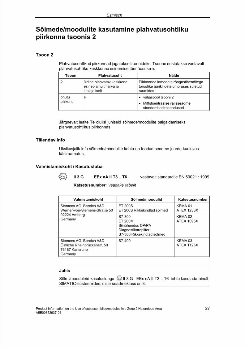
7/31/2019 Diagnose Repeater e
http://slidepdf.com/reader/full/diagnose-repeater-e 187/204
Estnisch
Product Information on the Use of subassemblies/modules in a Zone 2 Hazardous Area 27 A5E00352937-01
Sõlmede/moodulite kasutamine plahvatusohtlikupiirkonna tsoonis 2
Tsoon 2
Plahvatusohtlikud piirkonnad jagatakse tsoonideks. Tsoone eristatakse vastavaltplahvatusohtliku keskkonna esinemise tõenäosusele.
Tsoon Plahvatusoht Näide
2 üldine plahvatav keskkondesineb ainult harva jalühiajaliselt
Piirkonnad lamedate rõngastihenditegatorustike äärikliidete ümbruses suletudruumides
ohutupiirkond
ei • väljaspool tsooni 2
• Mittstsentraalse välisseadmestandardsed rakendused
Järgnevalt leaite Te olulisi juhiseid sõlmede/moodulite paigaldamiseksplahvatusohtlikus piirkonnas.
Täiendav info
Üksikasjalik info sõlmede/moodulite kohta on toodud seadme juurde kuuluvaskäsiraamatus.
Valmistamiskoht / Kasutusluba
II 3 G EEx nA II T3 .. T6 vastavalt standardile EN 50021 : 1999
Katsetusnumber: vaadake tabelit
Valmistamiskoht Sõlmed/moodulid Katsetusnumber
ET 200SET 200S Rikkekindlad sõlmed
KEMA 01 ATEX 1238X
Siemens AG, Bereich A&DWerner-von-Siemens-Straße 5092224 AmbergGermany
S7-300ET 200MSiinühendus DP/PADiagnostikarepiiter S7-300 Rikkekindlad sõlmed
KEMA 02 ATEX 1096X
Siemens AG, Bereich A&DÖstliche Rheinbrückenstr. 5076187 KarlsruheGermany
S7-400 KEMA 03 ATEX 1125X
Juhis
Sõlmi/mooduleid kasutusloaga II 3 G EEx nA II T3 .. T6 tohib kasutada ainultSIMATIC-süsteemides, mille seadmeklass on 3.

7/31/2019 Diagnose Repeater e
http://slidepdf.com/reader/full/diagnose-repeater-e 188/204
Estnisch
28 Product Information on the Use of subassemblies/modules in a Zone 2 Hazardous Area A5E00352937-01
Korrashoid
Parandamiseks tuleb sõlmed/moodulid saata valmistamiskohta. Parandustöid tohibteha ainult seal.
Eritingimused
1. Sõlmed/moodulid tuleb monteerida jaotuskarpi või metallkorpusesse. Needpeavad tagama kaitseastme vähemalt IP 54 (vastavalt standardile EN 60529).Seejuures peab arvesse võtma seadme paigaldamise keskkonna tingimusi.Korpuse jaoks peab tsooni 2 jaoks olema tootja juhis (vastavalt standardileEN 50021).
2. Kui selle korpuse kaabli juures või kaabelvaheliku (kaabelsisestuse) juurestöötingimustes saavutatakse temperatuur > 70 °C või, kui töötingimustestemperatuur soone hargnemiskoha juures võib olla > 80 °C, peavad kaablitermilised omadusd olema vastavuses tegelikult mõõdetud temperatuuridega.
3. Kasutatavad kaabelvahelikud (kaabelsisestused) peavad vastama nõutud IP-kaitseastmele ja osas 7.2 toodud nõuetele (vastavalt standardile EN 50021).
4. Kõik seadmed, kaasa arvatud lülitid, jt., mis SIMATIC-süsteemide sisendite javäljundite külge ühendatakse, peavad võimaldama plahvatuskaitsetüüpi EEx nA või EEx nC.
5. Peab rakendama abinõusid, et nimipinget üleminekute tõttu ei saaks ületatadaüle 40 %.
6. Ümbritseva keskkona temperatuurivahemik: 0° C kuni 60° C
7. Korpuse sisse tuleb sellisesse kohta, mis pärast avamist on hästi nähtav, pannasilt järgmise hoiatusega:
! EttevaatustKorpust tohib avada ainult lühikeseks ajals, näiteks visuaalse diagnostika jaoks.Seejuures ärge kasutage ühtegi lülitit ega võtke välja ega pange sisse ühtegisõlme ega lahutage ühtegi elektrijuhet (pistikühendused).Seda hoiatust võib mitte arvesse võtta, kui on teada, et ei esine mingitplahvatusohtlikku keskkonda.
Lubatud sõlmede/moodulite loetelu
Lubatud sõlmede/modulite loetelu leiate Te internetist:
http://www4.ad.siemens.de/view/cs/
lisas-ID 13702947.

7/31/2019 Diagnose Repeater e
http://slidepdf.com/reader/full/diagnose-repeater-e 189/204
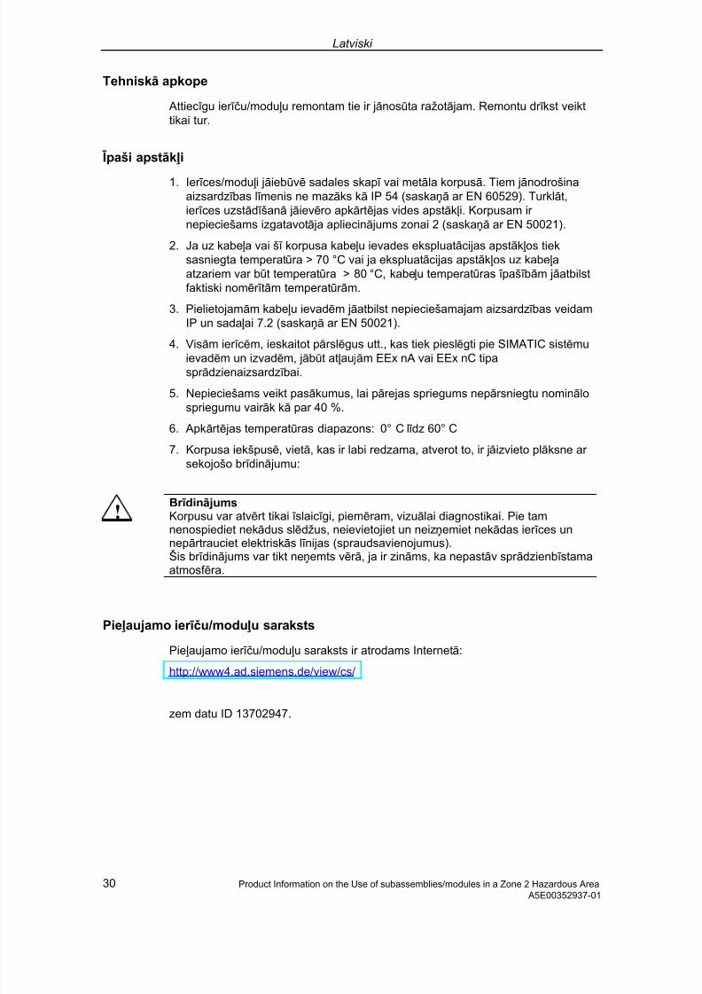
7/31/2019 Diagnose Repeater e
http://slidepdf.com/reader/full/diagnose-repeater-e 190/204
Latviski
30 Product Information on the Use of subassemblies/modules in a Zone 2 Hazardous Area A5E00352937-01
Tehniskā apkope
Attiec ī gu ier īču/modu ļu remontam tie ir jānosūta ražotā jam. Remontu dr ī kst veikttikai tur.
Ī paši apstāk ļi
1. Ier ī ces/modu ļi jāiebūvē sadales skap ī vai metāla korpusā. Tiem jānodrošinaaizsardz ī bas l ī menis ne mazāks kā IP 54 (saskaņā ar EN 60529). Turklāt,ier ī ces uzstād ī šanā jāievēro apkārtē jas vides apstāk ļi. Korpusam ir nepieciešams izgatavotā ja apliecinā jums zonai 2 (saskaņā ar EN 50021).
2. Ja uz kabe ļa vai š ī korpusa kabe ļu ievades ekspluatācijas apstāk ļos tieksasniegta temperatūra > 70 °C vai ja ekspluatācijas apstāk ļos uz kabe ļaatzariem var būt temperatūra > 80 °C, kabe ļu temperatūras ī paš ī bām jāatbilstfaktiski nomēr ī tām temperatūr ām.
3. Pielietojamām kabe ļu ievadēm jāatbilst nepieciešamajam aizsardz ī bas veidamIP un sada ļai 7.2 (saskaņā ar EN 50021).
4. Visām ier ī cēm, ieskaitot pārslēgus utt., kas tiek pieslēgti pie SIMATIC sistēmuievadēm un izvadēm, jābūt at ļaujām EEx nA vai EEx nC tipaspr ādzienaizsardz ī bai.
5. Nepieciešams veikt pasākumus, lai pārejas spriegums nepārsniegtu nominālospriegumu vair āk kā par 40 %.
6. Apkārtē jas temperatūras diapazons: 0° C l ī dz 60° C
7. Korpusa iekšpusē, vietā, kas ir labi redzama, atverot to, ir jāizvieto plāksne ar sekojošo br ī dinā jumu:
!
Br ī dinā jums Korpusu var atvērt tikai ī slaic ī gi, piemēram, vizuālai diagnostikai. Pie tamnenospiediet nekādus slēdžus, neievietojiet un neizņemiet nekādas ier ī ces unnepārtrauciet elektriskās l ī nijas (spraudsavienojumus).Šis br ī dinā jums var tikt neņemts vēr ā, ja ir zināms, ka nepastāv spr ādzienb ī stamaatmosf ēra.
Pie ļaujamo ier īču/modu ļu saraksts
Pie ļaujamo ier īču/modu ļu saraksts ir atrodams Internetā:
http://www4.ad.siemens.de/view/cs/
zem datu ID 13702947.
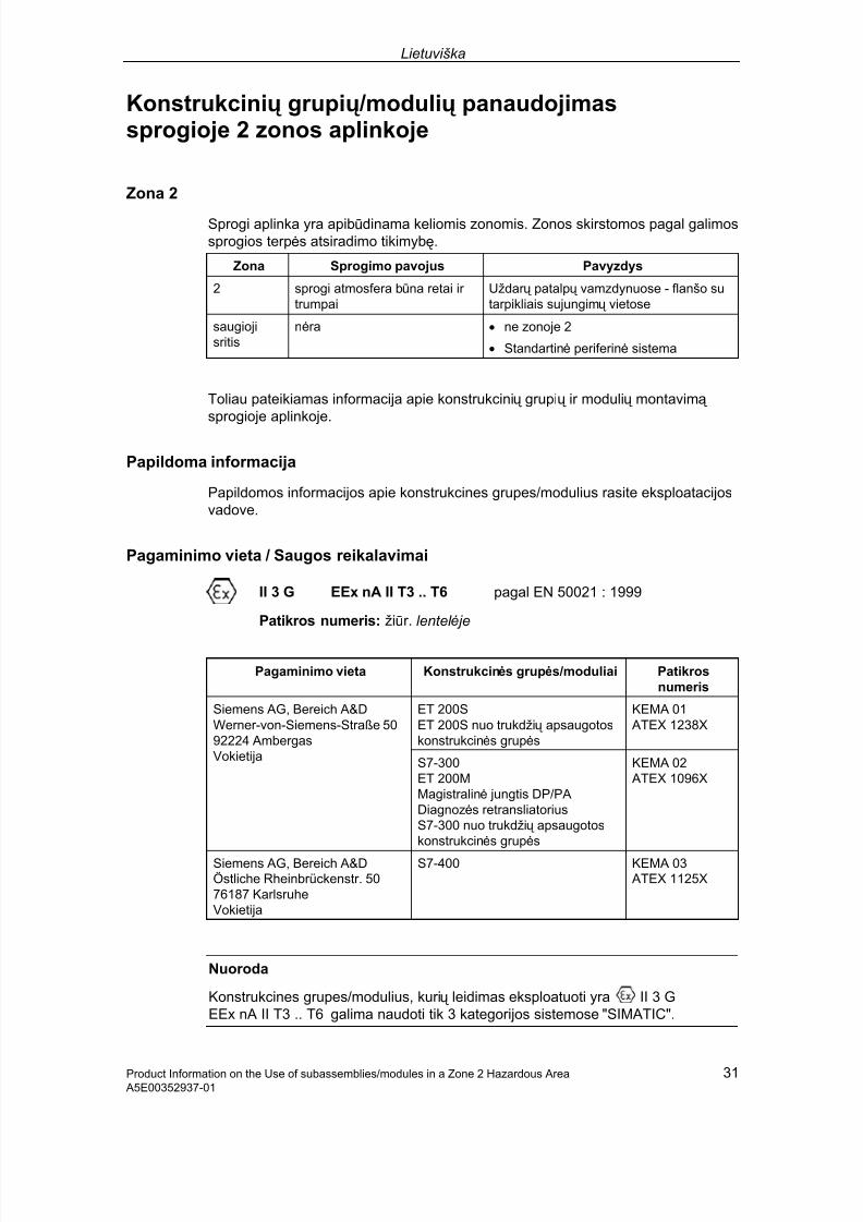
7/31/2019 Diagnose Repeater e
http://slidepdf.com/reader/full/diagnose-repeater-e 191/204
Lietuviška
Product Information on the Use of subassemblies/modules in a Zone 2 Hazardous Area 31 A5E00352937-01
Konstrukcinių grupių /modulių panaudojimassprogioje 2 zonos aplinkoje
Zona 2
Sprogi aplinka yra apibūdinama keliomis zonomis. Zonos skirstomos pagal galimossprogios terpės atsiradimo tikimybę.
Zona Sprogimo pavojus Pavyzdys
2 sprogi atmosfera būna retai ir trumpai
Uždar ų patalpų vamzdynuose - flanšo sutarpikliais sujungimų vietose
saugiojisritis
nėra • ne zonoje 2
• Standartinė periferinė sistema
Toliau pateikiamas informacija apie konstrukcinių grupių ir modulių montavimą sprogioje aplinkoje.
Papildoma informacija
Papildomos informacijos apie konstrukcines grupes/modulius rasite eksploatacijosvadove.
Pagaminimo vieta / Saugos reikalavimai
II 3 G EEx nA II T3 .. T6 pagal EN 50021 : 1999
Patikros numeris: žiūr. lentel ė je
Pagaminimo vieta Konstrukcinės grupės/moduliai Patikros
numeris
ET 200SET 200S nuo trukdžių apsaugotoskonstrukcinės grupės
KEMA 01 ATEX 1238X
Siemens AG, Bereich A&DWerner-von-Siemens-Straße 5092224 AmbergasVokietija S7-300
ET 200MMagistralinė jungtis DP/PADiagnozės retransliatoriusS7-300 nuo trukdžių apsaugotoskonstrukcinės grupės
KEMA 02 ATEX 1096X
Siemens AG, Bereich A&DÖstliche Rheinbrückenstr. 5076187 KarlsruheVokietija
S7-400 KEMA 03 ATEX 1125X
Nuoroda
Konstrukcines grupes/modulius, kurių leidimas eksploatuoti yra II 3 GEEx nA II T3 .. T6 galima naudoti tik 3 kategorijos sistemose "SIMATIC".

7/31/2019 Diagnose Repeater e
http://slidepdf.com/reader/full/diagnose-repeater-e 192/204
Lietuviška
32 Product Information on the Use of subassemblies/modules in a Zone 2 Hazardous Area A5E00352937-01
Priežiūra
Esant gedimams, konstrukcinę grupę/modulį išsių skite gamintojui. Tik jis galikvalifikuotai suremontuoti į taisą .
Specialiosios są lygos
1. Konstrukcines grupes/modulius montuokite jungimo spintoje arba metaliniamekorpuse. Korpuso ar jungimo spintos saugos klasė turi būti mažiausiai "IP 54"(pagal EN 60529). Būtina atsižvelgti į kitas aplinkos są lygas. Norint korpusą eksploatuoti zonoje 2, būtinas gamintojo pažymė jimas (pagal EN 50021).
2. Jei korpuso kabelio arba kabelio prijungimo temperatūra pakyla daugiau nei70 °C arba laidų atšakoje temperatūra padidė ja daugiau nei 80 °C, reikianaudoti kabelius, kurių terminės savybės atitinka išmatuotas temperatūrosvertes.
3. Kabelių sujungimai turi būti saugos klasės IP ir atitikti 7.2 skyriaus (pagalEN 50021) reikalavimus.
4. Visi prietaisai, į skaitant ir jungiklius, jungiami sistemų "SIMATIC" į eigose ir išeigose, turi būti tipo "EEx nA" arba "EEx nC" - apsaugoti nuo sprogimo.
5. Būtina imtis priemonių , kad pereinamų jų grandžių vardinė į tampa neviršytų 40 %.
6. Leistina aplinkos temperatūra: 0° C iki 60° C
7. Atidar ę korpusą , jo viduje gerai matomoje vietoje, į taisykite lentelę su į spė jimu:
! Įspė jimas Korpusą atidaryti tik trumpam laikui, pvz., patikrai. Neliesti jungiklių ,konstrukcinių grupių neištraukti ir nekišti, neatjungti elektrinių sujungimų (kištukinių sujungimų ).Šio į spė jimo galima nepaisyti, kai yra žinoma, jog darbinė aplinka yra nesprogi.
Leistinų konstrukcinių grupių /modulių są rašas
Leistinų konstrukcinių grupių /modulių są rašą rasite interneto puslapyje:
http://www4.ad.siemens.de/view/cs/
į vedę kodą 13702947.
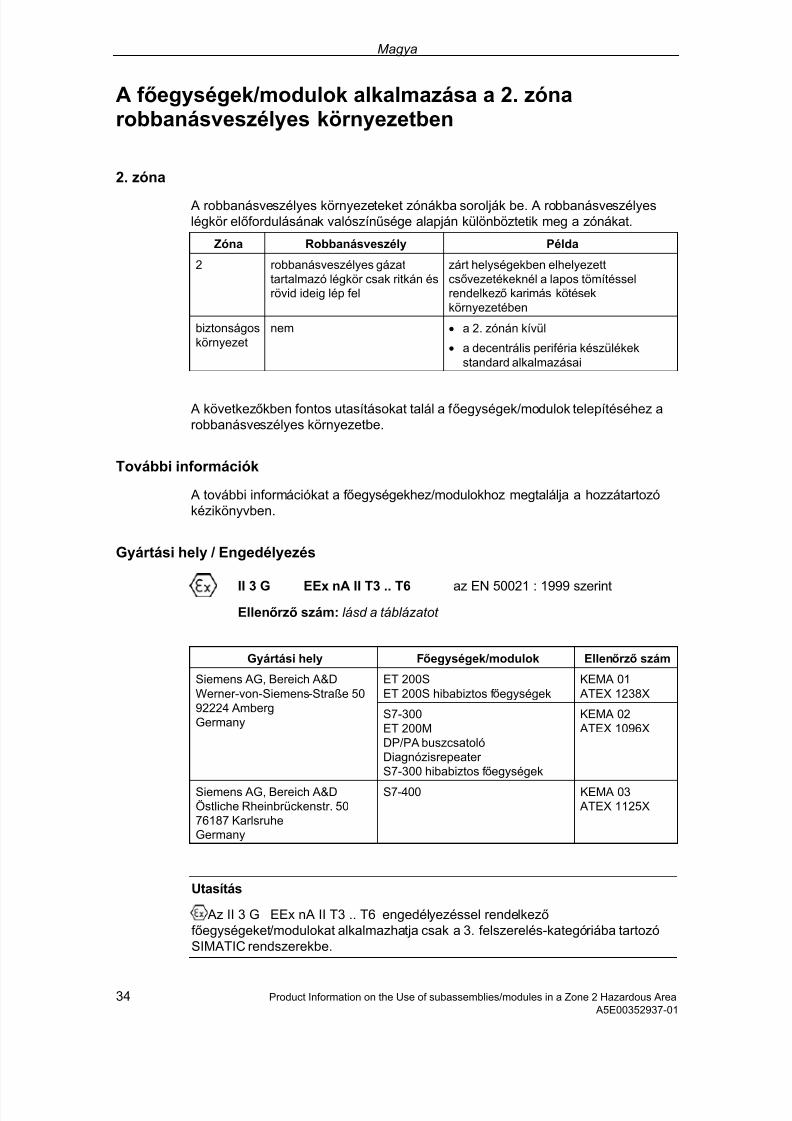
7/31/2019 Diagnose Repeater e
http://slidepdf.com/reader/full/diagnose-repeater-e 193/204
Magya
34 Product Information on the Use of subassemblies/modules in a Zone 2 Hazardous Area A5E00352937-01
A f őegységek/modulok alkalmazása a 2. zónarobbanásveszélyes környezetben
2. zóna
A robbanásveszélyes környezeteket zónákba sorolják be. A robbanásveszélyeslégkör előfordulásának valószínűsége alapján különböztetik meg a zónákat.
Zóna Robbanásveszély Példa
2 robbanásveszélyes gázattartalmazó légkör csak ritkán ésrövid ideig lép fel
zárt helységekben elhelyezettcsővezetékeknél a lapos tömítésselrendelkező karimás kötésekkörnyezetében
biztonságoskörnyezet
nem • a 2. zónán kívül
• a decentrális periféria készülékekstandard alkalmazásai
A következőkben fontos utasításokat talál a f őegységek/modulok telepítéséhez arobbanásveszélyes környezetbe.
További információk
A további információkat a f őegységekhez/modulokhoz megtalálja a hozzátartozókézikönyvben.
Gyártási hely / Engedélyezés
II 3 G EEx nA II T3 .. T6 az EN 50021 : 1999 szerintEllenőrző szám: lásd a táblázatot
Gyártási hely Főegységek/modulok Ellenőrző szám
ET 200SET 200S hibabiztos f őegységek
KEMA 01 ATEX 1238X
Siemens AG, Bereich A&DWerner-von-Siemens-Straße 5092224 AmbergGermany
S7-300ET 200MDP/PA buszcsatolóDiagnózisrepeater S7-300 hibabiztos f őegységek
KEMA 02 ATEX 1096X
Siemens AG, Bereich A&DÖstliche Rheinbrückenstr. 5076187 KarlsruheGermany
S7-400 KEMA 03 ATEX 1125X
Utasítás
Az II 3 G EEx nA II T3 .. T6 engedélyezéssel rendelkező f őegységeket/modulokat alkalmazhatja csak a 3. felszerelés-kategóriába tartozóSIMATIC rendszerekbe.
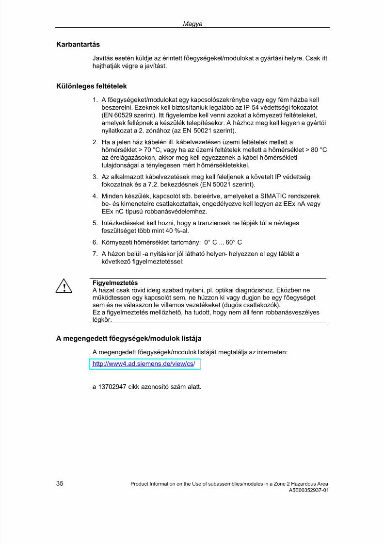
7/31/2019 Diagnose Repeater e
http://slidepdf.com/reader/full/diagnose-repeater-e 194/204
Magya
35 Product Information on the Use of subassemblies/modules in a Zone 2 Hazardous Area A5E00352937-01
Karbantartás
Javítás esetén küldje az érintett f őegységeket/modulokat a gyártási helyre. Csak itthajthatják végre a javítást.
Különleges feltételek
1. A f őegységeket/modulokat egy kapcsolószekrénybe vagy egy fém házba kellbeszerelni. Ezeknek kell biztosítaniuk legalább az IP 54 védettségi fokozatot(EN 60529 szerint). Itt figyelembe kell venni azokat a környezeti feltételeket,amelyek fellépnek a készülék telepítésekor. A házhoz meg kell legyen a gyártóinyilatkozat a 2. zónához (az EN 50021 szerint).
2. Ha a jelen ház kábelén ill. kábelvezetésen üzemi feltételek mellett ahőmérséklet > 70 °C, vagy ha az üzemi feltételek mellett a hőmérséklet > 80 °Caz érelágazásokon, akkor meg kell egyezzenek a kábel hőmérsékletitulajdonságai a ténylegesen mért hőmérsékletekkel.
3. Az alkalmazott kábelvezetések meg kell feleljenek a követelt IP védettségifokozatnak és a 7.2. bekezdésnek (EN 50021 szerint).
4. Minden készülék, kapcsolót stb. beleértve, amelyeket a SIMATIC rendszerekbe- és kimeneteire csatlakoztattak, engedélyezve kell legyen az EEx nA vagyEEx nC típusú robbanásvédelemhez.
5. Intézkedéseket kell hozni, hogy a tranziensek ne lépjék túl a névlegesfeszültséget több mint 40 %-al.
6. Környezeti hőmérséklet tartomány: 0° C ... 60° C
7. A házon belül -a nyitáskor jól látható helyen- helyezzen el egy táblát akövetkező figyelmeztetéssel:
! Figyelmeztetés A házat csak rövid ideig szabad nyitani, pl. optikai diagnózishoz. Eközben neműködtessen egy kapcsolót sem, ne húzzon ki vagy dugjon be egy f őegységetsem és ne válasszon le villamos vezetékeket (dugós csatlakozók).Ez a figyelmeztetés mellőzhető, ha tudott, hogy nem áll fenn robbanásveszélyeslégkör.
A megengedett f őegységek/modulok listája
A megengedett f őegységek/modulok listáját megtalálja az interneten:
http://www4.ad.siemens.de/view/cs/
a 13702947 cikk azonosító szám alatt.

7/31/2019 Diagnose Repeater e
http://slidepdf.com/reader/full/diagnose-repeater-e 195/204
Malti
Product Information on the Use of subassemblies/modules in a Zone 2 Hazardous Area 35 A5E00352937-01
Tqegħid tal-Komponenti / Modules fiż-Żona 2, fejnhemm Riskju ta' Spluż joni
Żona 2
Sezzjonijiet fejn hemm riskju ta' spluż joni jitqassmu f'żoni. Tagħmel distinzjoni bejnżona u oħra skond il-probabbiltà li jkun hemm ambjent li jista' jwassal għalspluż joni.
Żona Periklu ta' Spluż joni Eżempju
2 ambjent gassuż li jista' jisplodi jfeġġ rarament u għal żmienqasir
Żoni madwar flanġ ġojnts b'gaskits ċattif'kanni ġewwa spazji magħluqin
żona ż-żgura
le • barra miż-żona 2
• użu normali ta' devices periferalideċentralizzati
Issib hawn taħt indikazzjonijiet importanti għall-installazzjoni ta' komponenti /modules fiż-żona fejn hemm riskju ta' spluż joni.
Aktar Tagħrif
Aktar tagħrif fuq il-komponenti / modules jinstab fil-manwal ikkonċernat.
Post ta' Manifattura / Approvazzjoni
II 3 G EEx nA II T3 .. T6 skond EN 50021 : 1999
Numru taċ-Ċertifikat: ara t-tabella
Post ta' Manifattura Komponenti / Modules Numru taċ-
Ċertifikat
ET 200SET 200S modules ma jistgħux ifallu
KEMA 01 ATEX 1238X
Siemens AG, Bereich A&DWerner-von-Siemens-Straße 5092224 AmbergGermany
S7-300ET 200Mbus coupling DP/PARipetitur ta' dijanjosiS7-300 modules ma jistgħux ifallu
KEMA 02 ATEX 1096X
Siemens AG, Bereich A&DÖstliche Rheinbrückenstr. 5076187 KarlsruheGermany
S7-400 KEMA 03 ATEX 1125X
Nota
Komponenti / modules bl-approvazzjoni II 3 G EEx nA II T3 .. T6 jistgħu jintużaw biss ġewwa sistemi SIMATIC tal-kategorija 3.

7/31/2019 Diagnose Repeater e
http://slidepdf.com/reader/full/diagnose-repeater-e 196/204
Malti
36 Product Information on the Use of subassemblies/modules in a Zone 2 Hazardous Area A5E00352937-01
Manutenzjoni
Fil-każ li jkun hemm bżonn ta' tiswija, il-komponenti / modules ikkonċernatigħandhom jintbagħtu fil-post ta' manifattura. It-tiswijiet jistgħu jsiru biss f'dan il-post.
Kundizzjonijiet Speċ jali
1. Komponenti / modules għandhom jiġu mmontati ġewwa swiċċ kabinett jewkaxxa tal-metall. Dawn iridu jiggarantixxu protezzjoni mill-inqas tat-tip IP 54(skond EN 60529). Inti u tagħmel hekk, trid taħseb għall-kundizzjonijietambjentali ta' waqt l-installazzjoni tad-device. Irid ikun hemm dikjarazzjoni tal-manifatturier għall-kaxxa għaż-żona 2 (skond EN 50021).
2. Jekk fil-kejbil, jew fil-kaxxa mad-daħla għall-kejbil, tintlaħaq temperatura ta'aktar minn 70 °C taħt kundizzjonijiet ta' ħidma, jew jekk fil-post fejn jinfirdu l-wajers jista' jkun li hemm temperatura ta' aktar minn 80 °C, il-kejbil irid ikolluproprjetajiet ta' temperatura xierqa għat-temperaturi tabilħaqq imkejlin.
3. Id-daħliet għall-kejbil li jintużaw iridu jikkonformaw mat-tip ta' protezzjoni IPmitlub u t-taqsima 7.2 (skond EN 50021).
4. Id-devices kollha, swiċċijiet etc. inklużi, li jitqabbdu ma' l-inputs u l-outputs ta' sistemi SIMATIC, iridu jkunu approvati għal protezzjoni kontra spluż joni tat-tipEEx nA jew EEx nC.
5. Iridu jittieħdu miżuri biex il-vultaġġ nominali ma jitqabbiżx b'aktar minn 40%minħabba transitorji.
6. Varjazzjoni tat-temperatura ambjentali: 0° C sa 60° C
7. Għandha titqiegħed tabella bit-twissija li ġejja ġewwa l-kaxxa, f'post li jidher sewwara li tinfetaħ il-kaxxa:
! Twissija Il-kaxxa tista' tinfetaħ biss għal żmien qasir, per eżempju għal dijanjosi viżwali. Intiu tagħmel hekk, ma tista' tmiss l-ebda swiċċ, ddaħħal jew tneħħi l-ebda module utneħħi l-ebda kejbil elettriku (konnessjonijiet li tipplaggjahom).Tista' ma tagħtix każ ta' din it-twissija meta taf li m'hemmx riskju ta' spluż joni fl-ambjent.
Lista ta' Komponenti / Modules Approvati
Issib il-lista ta' komponenti / modules approvati fl-internet:
http://www4.ad.siemens.de/view/cs/
bin-numru ta' identifikazzjoni 13702947.

7/31/2019 Diagnose Repeater e
http://slidepdf.com/reader/full/diagnose-repeater-e 197/204
Polski
Product Information on the Use of subassemblies/modules in a Zone 2 Hazardous Area 37 A5E00352937-01
Zastosowanie grup konstrukcyjnych / modułów w 2strefie zagrożenia wybuchem
Strefa 2
Otoczenie zagrożone wybuchem dzielone jest na strefy. Strefy dzielą się zewzględu na stopień prawdopodobieństwa powstania atmosfery stwarzają cejmożliwość powstania wybuchu.
Strefa Niebezpieczeństwo eksplozji Przykład
2 atmosfera gazowa zzagrożeniem wybuchemwystępuje rzadko i na krótkiokres czasu
miejsca wokół łą cz w kanałachtechnicznych z opaskami przyprzewodach instalacyjnych wpomieszczeniach zamkniętych
obszar bezpieczny
nie • poza 2 stref ą
• standardowe zastosowaniedecentralnych urzą dzeń peryferyjnych
Dalej znajdą Państwo informacje dotyczą ce instalacji grup konstrukcyjnych /modułów w otoczeniu zagrożonym wybuchem.
Pozostałe informacje
Dalsze informacje dotyczą ce grup konstrukcyjnych / modułów znajdą państwo wodpowiedniej instrukcji.
Miejsce produkcji / Rejestracja
II 3 G EEx nA II T3 .. T6 stosownie do EN 50021 : 1999
Nr testu: zobacz tabela
Miejsce produkcji Grupy konstrukcyjne / moduły Nr testu
ET 200SET 200S grupy konstrukcyjneodporne na uszkodzenia
KEMA 01 ATEX 1238X
Siemens AG, Bereich A&DWerner-von-Siemens-Straße 5092224 AmbergNiemcy S7-300
ET 200MZbierają ce łą cze sprzężają ce
DP/PApowtarzacz diagnozyS7-300 grupy konstrukcyjneodporne na uszkodzenia
KEMA 02 ATEX 1096X
Siemens AG, Bereich A&DÖstliche Rheinbrückenstr. 5076187 KarlsruheNiemcy
S7-400 KEMA 03 ATEX 1125X

7/31/2019 Diagnose Repeater e
http://slidepdf.com/reader/full/diagnose-repeater-e 198/204
Polski
38 Product Information on the Use of subassemblies/modules in a Zone 2 Hazardous Area A5E00352937-01
Uwaga
Grupy konstrukcyjne / moduły zarejestrowane jako II 3 G EEx nA II T3 .. T6wolno stosować jedynie w systemach SIMATIC o 3 kategorii urzą dzenia.
KonserwacjaW celu naprawy należy odpowiednie grupy konstrukcyjne / moduły przesłać domiejsca produkcji. Jedynie serwis producenta jest upoważniony do dokonywanianapraw.
Warunki szczególne
1. Grupy konstrukcyjne / moduły muszą zostać zamontowane do skrzynkiochronnej lub metalowej puszki ochronnej. Muszą one spełniać wymagania conajmniej stopnia IP 54 (stosownie do EN 60529). Należy brać pod uwagę warunki otoczenia, w którym urzą dzenie będzie instalowane. Należy posiadać oświadczenie producenta dopuszczają ce puszkę do użytku w strefie 2(stosownie do EN 50021).
2. W przypadku, gdyby na przewodzie tej puszki podczas pracy temperaturamogła przekroczyć > 70 °C, lub żyła przewodu mogłaby osią gnąć temperatur ę > 80 °C, właściwości cieplne przewodu muszą zostać dobrane do takichwartości.
3. Wszystkie stosowane przewody muszą odpowiadać właściwemu stopniowiochrony IP oraz warunkom określonym w punkcie 7.2 (stosownie do EN50021).
4. Wszystkie urzą dzenia włą czają c w to przełą czniki itp., które podłą czane są dowejść lub wyjść systemów SIMATIC muszą być dopuszczone do ochrony
przeciw wybuchom typu EEx nA lub EEx nC.5. Muszą zostać spełnione takie warunki, aby napięcie miana w przejściach nie
mogło przekroczyć więcej niż 40 %.
6. Temperatura otoczenia: od 0° C do 60° C
7. W puszce w dobrze widocznym po otwarciu miejscu należy umieścić ostrzeżenie następują cej treści:
! Uwaga Puszkę wolno otworzyć jedynie na krótki okres czasu na przykład w celu kontrolioptycznej. Nie wolno przy tym naciskać na żaden z przełą czników, nie wolnowycią gać ani montować żadnej grupy konstrukcyjnej ani też odłą czać żadnychprzewodów elektrycznych (łą cza wsuwkowe).
Powyższego ostrzeżenia nie trzeba przestrzegać jeśli wiadomo jest, iż na miejscunie ma zagrożenia wybuchem.
Lista dopuszczonych grup konstrukcyjnych / modułów
Wykaz dopuszczonych grup konstrukcyjnych / modułów znajduje się na stronieinternetowej:
http://www4.ad.siemens.de/view/cs/
w części ID 13702947.

7/31/2019 Diagnose Repeater e
http://slidepdf.com/reader/full/diagnose-repeater-e 199/204
Slovensky
Product Information on the Use of subassemblies/modules in a Zone 2 Hazardous Area 39 A5E00352937-01
Použitie konštrukčných skupín / modulov v prostredí snebezpečenstvom výbuchu zóny 2
Zóna 2
Prostredia s nebezpečenstvom výbuchu sa rozdeľujú do zón. Zóny sa rozlišujúpodľa pravdepodobnosti prítomnosti atmosféry so schopnosťou výbuchu.
Zóna Nebezpečenstvo explózie Príklad
2 plynová atmosféra snebezpečenstvom výbuchu savyskytuje len zriedka akrátkodobo
priestory okolo prírubových spojov splochými tesneniami pri potrubnýchvedeniach v uzavretých priestoroch
bezpečnáoblasť
nie • mino zóny 2
• štandardné použitia decentrálnejperiférie
Ďalej nájdete dôležité pokyny pre inštaláciu konštrukčných skupín / modulov vprostredí s nebezpečenstvom výbuchu.
Ďalšie informácie
Ďalšie informácie ku konštrukčným skupinám / modulom nájdete v príslušnejpríručke.
Miesto vyhotovenia / Osvedčenie
II 3 G EEx nA II T3 .. T6 podľa EN 50021 : 1999Číslo skúšky : pozri tabuľ ka
Miesto vyhotovenia Konštrukčné skupiny / moduly Číslo skúšky
ET 200SET 200S konštrukčné skupinyodolné voči poruchám
KEMA 01 ATEX 1238X
Siemens AG, divízia A&DWerner-von-Siemens-Straße 5092224 AmbergNemecko S7-300
ET 200MZbernicový väzbový člen DP/PAopakovač diagnózyS7-300 konštrukčné skupinyodolné voči poruchám
KEMA 02 ATEX 1096X
Siemens AG, divízia A&DÖstliche Rheinbrückenstr. 5076187 KarlsruheNemecko
S7-400 KEMA 03 ATEX 1125X
Upozornenie
Konštrukčné skupiny / moduly s osvedčením II 3 G EEx nA II T3 .. T6 sa smúpoužívať len v systémoch SIMATIC kategórie zariadenia 3.

7/31/2019 Diagnose Repeater e
http://slidepdf.com/reader/full/diagnose-repeater-e 200/204
Slovensky
40 Product Information on the Use of subassemblies/modules in a Zone 2 Hazardous Area A5E00352937-01
Údržba
Za účelom opravy sa musia príslušné konštrukčné skupiny / moduly zaslať namiesto vyhotovenia. Oprava sa smie vykonávať len na tomto mieste !
Špeciálne podmienky
1. Konštrukčné skupiny / moduly sa musia vmontovať do spínacej skrine alebo dokovového puzdra schránky. Tie musia zabezpečovať druh ochrany minimálneIP 54 (podľa EN 60529). Pritom je potrebné zohľadniť podmienky prostredia, doktorého sa bude zariadenie inštalovať. V prípade puzdra musí existovať vyhlásenie výrobcu pre zónu 2 (podľa EN 50021).
2. V prípade, že na kábli, prípadne na káblovom prívode tohto puzdra presiahneteplota pri prevádzkových podmienkach hodnotu > 70 °C, alebo ak na vetve žilymôže byť pri prevádzkových podmienkach teplota > 80 °C, musia tepelnévlastnosti kábla vyhovovať skutočne nameraným hodnotám.
3. Všetky použité káblové prívody musia zodpovedať požadovanému druhuochrany IP a odseku 7.2 (podľa EN 50021).
4. Všetky zariadenia, vrátane prepínača, atď., ktoré sa pripoja na vstupy a výstupysystémov SIMATIC, musia byť schválené pre ochranu voči výbuchutypu EEx nA alebo EEx nC.
5. Musia sa splniť také opatrenia, aby sa menovité napätie cez prechody nemohloprekročiť o viac ako 40 %.
6. Rozsah okolitých teplôt: 0° C až 60° C
7. V puzdre je na dobre viditeľné miesto po otvorení potrebné umiestniť štítok snasledovnou výstrahou:
! Výstraha Puzdro sa môže otvoriť len počas krátkej doby, napríklad pre vizuálnu diagnózu.Nestlačte pritom žiadny prepínač, nevytiahnite alebo nezasuňte žiadnukonštrukčnú skupinu a neoddeľte žiadne elektrické vedenia (zástr čkovéspojenia).Túto výstrahu si nemusíte všímať v takom prípade, ak je známe, že sa na miestenevyskytuje atmosféra s nebezpečenstvom výbuchu.
Zoznam dovolených konštrukčných skupín / modulov
Zoznam dovolených konštrukčných skupín / modulov sa nachádza na internete :
http://www4.ad.siemens.de/view/cs/
v článku ID 13702947.

7/31/2019 Diagnose Repeater e
http://slidepdf.com/reader/full/diagnose-repeater-e 201/204
Slovensko
Product Information on the Use of subassemblies/modules in a Zone 2 Hazardous Area 41 A5E00352937-01
Uporaba sklopov/modulov v eksplozivno ogroženemobmoč ju cone 2
Cona 2
Eksplozivno ogrožena območ ja se delijo na cone. Cone se ločijo po verjetnostiprisotnosti eksplozivne atmosfere.
Cona Nevarnost eksplozije Primer
2 eksplozivna zmes plinov vatmosferi je redka in traja lekratko.
Območ ja okoli prirobnih spojev z ploskimitesnili pri cevnih napeljavah v zaprtihprostorih.
sigurnoobmoč je
ne • izven cone 2
• Standardna uporaba decentralneperiferije.
Sledijo pomembni napotki o inštalaciji sklopov/modulov v eksplozivno ogroženemobmoč ju.
Nadaljnje informacije
Nadaljnje informacije o sklopih/modulih najdete v priloženem priročniku.
Mesto izdelave / Dovoljenje - Atest
II 3 G EEx nA II T3 .. T6 po EN 50021 : 1999
kontrolna številka: glej tabelo
Mesto izdelave Sklopi/moduli kontrolna
številka:
ET 200SET 200S Sklopi varovani protiokvari
KEMA 01 ATEX 1238X
Siemens AG, Bereich A&DWerner-von-Siemens-Straße 5092224 AmbergGermany S7-300
ET 200Mbus vezava DP/PADiagnozni repeater S7-300 Sklopi varovani proti okvari
KEMA 02 ATEX 1096X
Siemens AG, Bereich A&DÖstliche Rheinbrückenstr. 5076187 KarlsruheGermany
S7-400 KEMA 03 ATEX 1125X
Opozorilo
Sklopi/moduli z dovoljenjem II 3 G EEx nA II T3 .. T6 se lahko uporabijo samov SIMATIC-Sistemih kategorije 3 .

7/31/2019 Diagnose Repeater e
http://slidepdf.com/reader/full/diagnose-repeater-e 202/204
Slovensko
42 Product Information on the Use of subassemblies/modules in a Zone 2 Hazardous Area A5E00352937-01
Vzdrževanje
V primeru popravila pošljete sklope/module na kraj izdelave. Popravila lahkoizvajajo samo na tem naslovu!
Posebni pogoji
1. Sklopi/moduli se morajo vgraditi v elektro omaro ali metalno ohišje.Omara/ohišje mora zadostiti varovanju IP 54 (po EN 60529). Pri tem jepotrebno upoštevati tudi pogoje okolice, v kateri se naprava nahaja. Ohišjemora imeti izjavo (atest) proizvajalca za uporabo v coni 2 (po EN 50021).
2. Če na kablu oz. uvodnici tega ohišja v režimu obratovanja temperatura doseževrednost > 70 °C ali če doseže na razcepih vodnikov v obratovanju temperaturavrednost > 80 °C, se morajo temperaturne lastnosti kablov skladati z dejanskonamerjenimi.
3. Uporabljene uvodnice morajo ustrezati predpisani IP zaščiti in poglavju 7.2 (poEN 50021).
4. Vse naprave, vključno s stikali itd., ki so priklopljene na vhodih oz. izhodihsistemov SIMATIC, morajo biti odobrene za zaščito proti eksplozijam tipa
EEx nA ali EEx nC.
5. Zagotoviti se mora, da nazivna napetost ne prekorači več kot 40% pritranzienci (preklopih, vklopih,...).
6. Temperaturno območ je okolice: 0° C do 60° C
7. V notranjosti ohišja, na odprtem dobro vidljivem mestu, se pritrdi napis znaslednjim opozorilom:
!
Opozorilo Ohišje se lahko odpre samo za kratek čas, npr. za vizualno diagnozo. Pri tem nevklapljajte/izklaplajte stikal, sklopov ali električnih vodnikov (vtičnih spojev).Opozorilo ne velja, kadar je znano, da ni eksplozivne atmosfere.
Seznam dovoljenih sklopov/modulov
Seznam dovoljenih sklopov/modulov najdete na internetu na spletni strani:
http://www4.ad.siemens.de/view/cs/
pod ID prispevka 13702947.
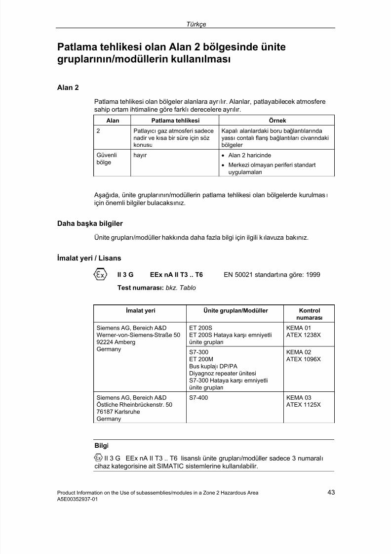
7/31/2019 Diagnose Repeater e
http://slidepdf.com/reader/full/diagnose-repeater-e 203/204
Türkçe
Product Information on the Use of subassemblies/modules in a Zone 2 Hazardous Area 43 A5E00352937-01
Patlama tehlikesi olan Alan 2 bölgesinde ünitegruplar ının/modüllerin kullanılması
Alan 2
Patlama tehlikesi olan bölgeler alanlara ayr ılır. Alanlar, patlayabilecek atmosferesahip ortam ihtimaline göre farklı derecelere ayr ılır.
Alan Patlama tehlikesi Örnek
2 Patlayıcı gaz atmosferi sadecenadir ve kısa bir süre için sözkonusu
Kapalı alanlardaki boru bağlantılar ındayassı contalı flanş bağlantılar ı civar ındakibölgeler
Güvenlibölge
hayır • Alan 2 haricinde
• Merkezi olmayan periferi standartuygulamalar ı
Aşağıda, ünite gruplar ının/modüllerin patlama tehlikesi olan bölgelerde kurulması için önemli bilgiler bulacaksınız.
Daha başka bilgiler
Ünite gruplar ı/modüller hakkında daha fazla bilgi için ilgili kılavuza bakınız.
İmalat yeri / Lisans
II 3 G EEx nA II T3 .. T6 EN 50021 standartına göre: 1999
Test numarası
:bkz. Tablo
İmalat yeri Ünite gruplar ı /Modüller Kontrolnumarası
ET 200SET 200S Hataya kar şı emniyetliünite gruplar ı
KEMA 01 ATEX 1238X
Siemens AG, Bereich A&DWerner-von-Siemens-Straße 5092224 AmbergGermany S7-300
ET 200MBus kuplajı DP/PADiyagnoz repeater ünitesiS7-300 Hataya kar şı emniyetli
ünite gruplar ı
KEMA 02 ATEX 1096X
Siemens AG, Bereich A&DÖstliche Rheinbrückenstr. 5076187 KarlsruheGermany
S7-400 KEMA 03 ATEX 1125X
Bilgi
II 3 G EEx nA II T3 .. T6 lisanslı ünite gruplar ı/modüller sadece 3 numaralı cihaz kategorisine ait SIMATIC sistemlerine kullanılabilir.

7/31/2019 Diagnose Repeater e
http://slidepdf.com/reader/full/diagnose-repeater-e 204/204
Türkçe
Bakım ve koruma
Bir onar ım gerekli olması halinde, ilgili ünite gruplar ı/modüller imalat yerinegönderilmelidir. Onar ım sadece orada yapılabilir ve yapılmalıdır.
Özel koşullar
1. Ünite gruplar ı/modüller bir şalter dolabı içine veya metal kasa içine monteedilmelidir. Bu kasalar en az IP 54 (EN 60529 standartına göre) koruma türüneait olmalıdır. Burada, cihazın kurulduğu çevre koşullar ı dikkate alınmalıdır.Kullanılacak kasa için, alan 2 için geçerli bir üretici beyanı mevcut olmalıdır (EN 50021 standartına istinaden).
2. Kabloda ya da bu kasanın kablo girişindeki işletme koşullar ında sıcaklık > 70 °Coluyorsa veya işletme koşullar ında kablo telleri (damarlar ı) ayr ılma noktasındasıcaklık > 80 °C olma ihtimali varsa, kablonun sıcaklık ile ilgili özellikleri,gerçekten ölçülmüş sıcaklıklara uygun olmalıdır.
3. Kullanılmış olan kablo girişleri, talep edilen IP koruma türüne ve bölüm 7.2(EN 50021 standartına göre) dahilindeki taleplere uygun olmalıdır.
4. SIMATIC sistemlerinin giriş ve çıkışlar ına bağlanan tüm cihazlar (şalterler vs.