Inunina.stidue.net/Universita' di Trieste/Ingegneria Industriale e... · In tro duction High p...
48
Transcript of Inunina.stidue.net/Universita' di Trieste/Ingegneria Industriale e... · In tro duction High p...

Trace Cache� a Low Latency Approach to High Bandwidth
Instruction Fetching
Eric Rotenberg Steve Bennett Jim Smith
April ��� ����
Abstract
Superscalar processors require su�cient instruction fetch bandwidth to feed their highly par�allel execution cores� Fetch bandwidth is determined by a number of factors� namely instructioncache hit rate� branch prediction accuracy� and taken branches in the instruction stream� Takenbranches introduce the problem of noncontiguous instruction fetching� the dynamic instructionsequence exists in the cache� but the instructions are not in contiguous cache locations� Thisreport considers the problem of fetching noncontiguous blocks of instructions in a single cycle�
We propose the trace cache� a special instruction cache that captures dynamic instructionsequences� Each line in the trace cache stores a dynamic code sequence� which may containone or more taken branches� Dynamic sequences are built up as the program executes� If apredicted dynamic sequence exists in the trace cache� it can be fed directly to the decoders�
We investigate other methods for fetching noncontiguous instruction sequences in a singlecycle� The Branch Address Cache ��� and Collapsing Buer �� achieve high bandwidth byfeeding multiple noncontiguous fetch addresses to an interleaved cache and performing complexalignment on the instructions as they come out of the cache� Inevitably� this approach lengthensthe critical path through the instruction fetch unit� Extra stages in the fetch pipeline increasebranch mispredict recovery time� decreasing overall performance� Our approach moves com�plexity due to noncontiguous instruction fetching o the critical path and onto the �ll side ofthe trace cache�
We compare the performance of the trace cache against other fetch designs� We �rst considersimple instruction fetching mechanisms that predict only one branch at a time or fetch only up tothe �rst taken branch� We also consider more aggressive methods that are able to fetch beyondmultiple taken branches� For integer benchmarks� the trace cache improves performance onaverage by � � over the fetch unit limited to one basic block per cycle� and �� over the fetchunit limited to multiple contiguous basic blocks� The corresponding improvements for �oatingpoint benchmarks are �� and ��� Further� the trace cache consistently performs better thanthe other high bandwidth fetch mechanisms studied even if single�cycle fetch latency is assumed
across all mechanisms� Simulations with more realistic latencies for the other high bandwidthapproaches� based on pipeline stages before and after the instruction cache� show that the tracecache clearly outperforms other approaches� on average� ��� and �� better than the nexthighest performer for integer and �oating point benchmarks� respectively�
�
� Introduction
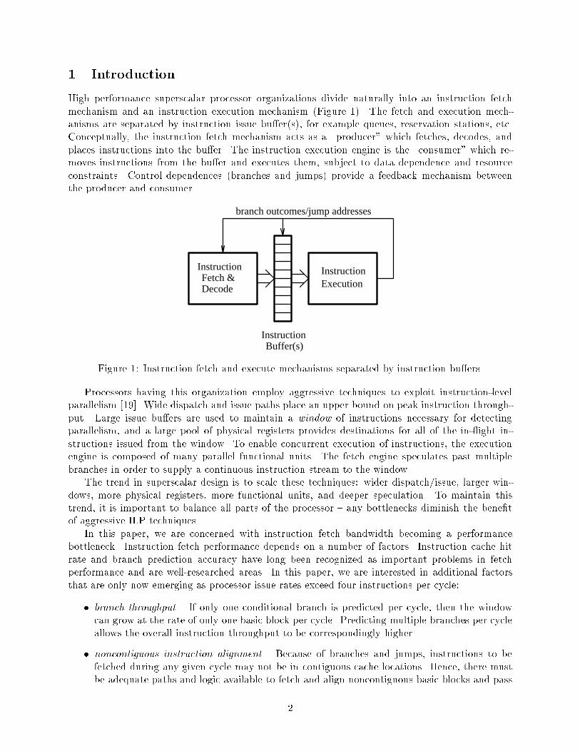
High performance superscalar processor organizations divide naturally into an instruction fetchmechanism and an instruction execution mechanism �Figure ��� The fetch and execution mech�anisms are separated by instruction issue bu�er�s�� for example queues� reservation stations� etc�Conceptually� the instruction fetch mechanism acts as a �producer which fetches� decodes� andplaces instructions into the bu�er� The instruction execution engine is the �consumer which re�moves instructions from the bu�er and executes them� subject to data dependence and resourceconstraints� Control dependences �branches and jumps� provide a feedback mechanism betweenthe producer and consumer�
InstructionFetch &Decode
Instruction
branch outcomes/jump addresses
Buffer(s)
ExecutionInstruction
Figure � Instruction fetch and execute mechanisms separated by instruction bu�ers�
Processors having this organization employ aggressive techniques to exploit instruction�levelparallelism ��� � Wide dispatch and issue paths place an upper bound on peak instruction through�put� Large issue bu�ers are used to maintain a window of instructions necessary for detectingparallelism� and a large pool of physical registers provides destinations for all of the in��ight in�structions issued from the window� To enable concurrent execution of instructions� the executionengine is composed of many parallel functional units� The fetch engine speculates past multiplebranches in order to supply a continuous instruction stream to the window�The trend in superscalar design is to scale these techniques wider dispatch�issue� larger win�
dows� more physical registers� more functional units� and deeper speculation� To maintain thistrend� it is important to balance all parts of the processor � any bottlenecks diminish the bene�tof aggressive ILP techniques�In this paper� we are concerned with instruction fetch bandwidth becoming a performance
bottleneck� Instruction fetch performance depends on a number of factors� Instruction cache hitrate and branch prediction accuracy have long been recognized as important problems in fetchperformance and are well�researched areas� In this paper� we are interested in additional factorsthat are only now emerging as processor issue rates exceed four instructions per cycle
� branch throughput � If only one conditional branch is predicted per cycle� then the windowcan grow at the rate of only one basic block per cycle� Predicting multiple branches per cycleallows the overall instruction throughput to be correspondingly higher�
� noncontiguous instruction alignment � Because of branches and jumps� instructions to befetched during any given cycle may not be in contiguous cache locations� Hence� there mustbe adequate paths and logic available to fetch and align noncontiguous basic blocks and pass
�
them up the pipeline� That is� it is not enough for the instructions to be present in the cache�it must also be possible to access them in parallel�
� fetch unit latency � Pipeline latency has a profound impact on processor performance� Thisis due to the cost of re�lling the pipeline after incorrect control speculation� In the case ofthe fetch unit� we are concerned with the startup cost of redirecting fetching after resolvinga branch mispredict� jump� or instruction cache miss� Inevitably� the need for higher branchthroughput and noncontiguous instruction alignment will increase fetch unit latency� yet waysmust be found to minimize the latency impact�
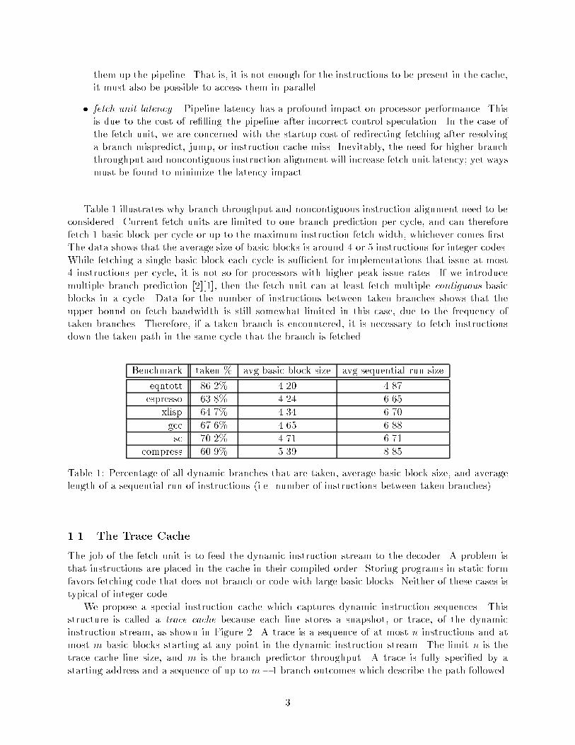
Table � illustrates why branch throughput and noncontiguous instruction alignment need to beconsidered� Current fetch units are limited to one branch prediction per cycle� and can thereforefetch � basic block per cycle or up to the maximum instruction fetch width� whichever comes �rst�The data shows that the average size of basic blocks is around � or � instructions for integer codes�While fetching a single basic block each cycle is su�cient for implementations that issue at most� instructions per cycle� it is not so for processors with higher peak issue rates� If we introducemultiple branch prediction �� �� � then the fetch unit can at least fetch multiple contiguous basicblocks in a cycle� Data for the number of instructions between taken branches shows that theupper bound on fetch bandwidth is still somewhat limited in this case� due to the frequency oftaken branches� Therefore� if a taken branch is encountered� it is necessary to fetch instructionsdown the taken path in the same cycle that the branch is fetched�
Benchmark taken � avg basic block size avg sequential run size
eqntott ����� ���� ����
espresso ����� ���� ����
xlisp ����� ���� ����
gcc ����� ���� ����
sc ����� ���� ����
compress ����� ���� ����
Table � Percentage of all dynamic branches that are taken� average basic block size� and averagelength of a sequential run of instructions �i�e� number of instructions between taken branches��
��� The Trace Cache
The job of the fetch unit is to feed the dynamic instruction stream to the decoder� A problem isthat instructions are placed in the cache in their compiled order� Storing programs in static formfavors fetching code that does not branch or code with large basic blocks� Neither of these cases istypical of integer code�We propose a special instruction cache which captures dynamic instruction sequences� This
structure is called a trace cache because each line stores a snapshot� or trace� of the dynamicinstruction stream� as shown in Figure �� A trace is a sequence of at most n instructions and atmost m basic blocks starting at any point in the dynamic instruction stream� The limit n is thetrace cache line size� and m is the branch predictor throughput� A trace is fully speci�ed by astarting address and a sequence of up to m� � branch outcomes which describe the path followed�
�

The �rst time a trace is encountered� it is allocated a line in the trace cache� The line is �lled asinstructions are fetched from the instruction cache� If the same trace is encountered again in thecourse of executing the program� i�e� the same starting address and predicted branch outcomes� itwill be available in the trace cache and is fed directly to the decoder� Otherwise� fetching proceedsnormally from the instruction cache�
ttA
2nd basic block
1st basic block
3rd basic block (still filling)
Att
TRACE CACHETRACE CACHE
to DECODER
DYNAMIC INSTRUCTION STREAM
trace {A:taken,taken} trace {A:taken,taken}
A At t
Fill New Trace from Instruction Cache Access existing trace using A and predictions(t,t)
t t
later...
Figure � High level view of the trace cache approach� The instruction trace starting at addressA and continuing past � taken �t� branches is �lled into the trace cache at the �rst encounter andlater fetched in a single cycle� The address A and � branch predictions are used to lookup the tracein the trace cache�
The trace cache approach relies on dynamic sequences of code being reused� This may be thecase for two reasons
� temporal locality � like the primary instruction cache� the trace cache can count on instructionswhich have been recently used being used again in the near future�
� branch behavior � most branches tend to be biased towards one direction� which is why branchprediction accuracy is usually high� Thus� it is likely that certain paths through the control�ow graph will be followed frequently�
��� Related Prior Work
Three recent studies have focused on high bandwidth instruction fetching and are closely relatedto the research reported here� All of these attempt to fetch multiple� possibly noncontiguous basicblocks each cycle from the instruction cache�First� Yeh� Marr� and Patt �� consider a fetch mechanism that provides high bandwidth by
predicting multiple branch target addresses every cycle� The method features a Branch Address
�

Cache� a natural extension of the branch target bu�er �� � With a branch target bu�er� a singlebranch prediction and a BTB hit produces the starting address of the next basic block� Similarly�a hit in the branch address cache combined with multiple branch predictions produces the start�ing addresses of the next several basic blocks� These addresses are fed into a highly interleavedinstruction cache to fetch multiple basic blocks in a single cycle�A second study by Franklin and Dutta �� uses a similar approach to the branch address cache
�providing multiple branch targets�� but with a new method for predicting multiple branches in asingle cycle� Their approach hides multiple individual branch predictions within a single prediction�e�g� rather than make � branch predictions� make � prediction that selects from among � paths�This enables the use of more accurate two�level predictors�Another hardware scheme proposed by Conte� Mills� Menezes� and Patel �� uses two passes
through an interleaved branch target bu�er� Each pass through the branch target bu�er producesa fetch address� allowing two nonadjacent cache lines to be fetched� In addition� the interleavedbranch target bu�er enables detection of any number of branches in a cache line� In particular� thedesign is able to detect short forward branches within a line and eliminate instructions betweenthe branch and its target using a collapsing bu�er� The work also proposes compiler techniques toreduce the frequency of taken branches�Two previously proposed hardware structures are similar to the trace cache but exist in di�erent
applications� The �ll unit� proposed by Melvin� Shebanow and Patt ��� � caches RISC�like instruc�tions which are derived from a CISC instruction stream� This predecoding eased the problem ofsupporting a complex instruction set such as VAX on the HPS restricted data�ow engine� Franklinand Smotherman �� extended the �ll unit�s role to dynamically assemble VLIW�like instructionwords from a RISC instruction stream� which are then stored in a shadow cache� The goal of thisstructure is to ease the dependency checking and issue complexity of a wide issue processor�
��� Problems with Other Fetch Mechanisms
Recall that the job of the fetch unit is to feed the dynamic instruction stream to the decoder� Unlikethe trace cache approach� previous designs have only the conventional instruction cache� containinga static form of the program� to work with� Every cycle� instructions from noncontiguous locationsmust be fetched from the instruction cache and assembled into the predicted dynamic sequence�There are problems with this approach
� Pointers to all of the noncontiguous instruction blocks must be generated before fetching canbegin� This implies a level of indirection� through some form of branch target table �branchtarget bu�er� branch address cache� etc��� which translates into an additional pipeline stagebefore the instruction cache�
� The instruction cache must support simultaneous access to multiple� noncontiguous cachelines� This forces the cache to be multiported� if multiporting is done through interleaving�bank con�icts are su�ered�
� After fetching the noncontiguous instructions from the cache� they must be assembled intothe dynamic sequence� Instructions must be shifted and aligned to make them appear con�tiguous to the decoder� This most likely translates into an additional pipeline stage after theinstruction cache�
The trace cache approach avoids these problems by caching dynamic instruction sequencesthemselves� ready for the decoder� If the predicted dynamic sequence exists in the trace cache�it does not have to be recreated on the �y from the instruction cache�s static representation�
�

In particular� no additional stages before or after the instruction cache are needed for fetchingnoncontiguous instructions� The stages do exist� but not on the critical path of the fetch unit �rather� on the �ll side of the trace cache� The cost of this approach is redundant instruction storagethe same instructions may reside in both the primary cache and the trace cache� and there evenmight be redundancy among lines in the trace cache�
��� Contributions
As with prior work in high bandwidth instruction fetching� this report demonstrates the importanceof fetching past multiple possibly�taken branches each cycle� Unlike other work in the area� we placeequal emphasis on fetch unit latency� The end result is the trace cache as a means for low latency�high bandwidth instruction fetching�Another contribution is a detailed simulation study comparing proposed high bandwidth fetch
mechanisms including the trace cache� Previously� the approaches described in Section ��� couldnot be directly compared due to di�erent experimental setups � di�erent ISAs� processor executionmodels� branch predictors� caches� workloads� and metrics�In the course of this work� many microarchitectural and logic design issues arose� We looked at
design issues for not only the trace cache� but other proposed mechanisms as well� The results ofthis detailed study are documented in the Appendix of this report�
��� Paper Overview
In the next section the trace cache fetch unit is described in detail� Section � follows up with ananalysis of other proposed high bandwidth fetch mechanisms� In Section � we describe the simu�lation methodology including the processor model� workload� and performance metric� Simulationresults are presented in Section �� As part of the study in Section �� we compare the trace cachewith previously proposed high performance fetch mechanisms on a �level playing �eld in terms ofcaches� branch prediction methods� execution engines� and performance measures�
�

� Trace Cache
In Section ��� we introduced the concept of the trace cache � an instruction cache which capturesdynamic instruction sequences� We now present a trace cache implementation� Because the tracecache is not intended to replace the conventional instruction cache or the fetch hardware aroundit� we begin with a description of the core fetch mechanism� We then show how the core fetch unitis augmented with the trace cache�
��� Core Fetch Unit
The core fetch unit is implemented using established hardware schemes� It is called interleavedsequential in �� � Fetching up to the �rst predicted taken branch each cycle can be done usingthe combination of an accurate multiple branch predictor �� � an interleaved branch target bu�er�BTB� �� �� � a return address stack �RAS� ��� � and a ��way interleaved instruction cache �� �� �Refer to Figure ��The core fetch unit is designed to fetch as many contiguous instructions possible� up to a
maximum instruction limit and a maximum branch limit� The instruction constraint is imposed bythe width of the datapath� and the branch constraint is imposed by the branch predictor throughput�For demonstration� a fetch limit of �� instructions and � branches is used throughout�
A
taken branch
16-way Interleaved
A
BRANCH TARGET BUFFER
A
fetchBTB
valid instructionsbit vectors
targetaddress
Line Size = 16 Instructions
to decoder
INTERCHANGE, SHIFT, MASK
2-Way Interleaved
LOGIC
Instruction Cache
STACKADDRESSRETURN
not takenbranch
111111000000000000000000001111111st:
2nd:
address
BRANCH
PREDICTOR
Line Size = 16 Instructions
MULTIPLE
3
"01x"
Figure � The core fetch unit�
�

The cache is interleaved so that � consecutive cache lines can be accessed� this allows fetchingsequential code that spans a cache line boundary� always guaranteeing a full cache line or up tothe �rst taken branch �� � This scheme requires minimal complexity for aligning instructions ���logic to swap the order of the two cache lines �interchange switch�� ��� a left�shifter to align theinstructions into a ���wide instruction latch� and ��� logic to mask o� unused instructions�All banks of the BTB are accessed in parallel with the instruction cache� They serve the role
of ��� detecting branches in the instructions currently being fetched and ��� providing their targetaddresses� in time for the next fetch cycle� The BTB must be n�way interleaved� where n is thenumber of instructions in a cache line� This is so that all instructions within a cache line can bechecked for branches in parallel �� � The BTB can detect other types of control transfer instructionsas well� If a jump is detected� the jump address may be predicted� �Jump target predictions arenot considered in this paper� however�� Return addresses can almost always be obtained with nopenalty by using a call�return stack� If the BTB detects a return in the instructions being fetched�it pops the address at the top of the RAS�Notice in Figure � that the branch predictor is separate from the BTB� This is to allow for
predictors that are more accurate than the ��bit or ��bit counters normally stored with each branchentry in the BTB� While storing counters with each branch achieves multiple branch predictiontrivially� branch prediction accuracy is limited� Branch prediction is fundamental to ILP� andshould have precedence over other factors� For high branch prediction accuracy� we use a �kBGAg���� correlated branch predictor ��� � The �� bit global branch history register indexes into asingle pattern history table� This predictor was chosen for its accuracy and because it is more easilyextended to multiple branch predictions than other predictors which require address information�� �� � It is relatively straightforward to extend the single correlated branch predictor to multiplepredictions each cycle� as proposed in �� � An actual hardware implementation is shown in Figure ��BTB logic combines the BTB hit information with the branch predictions to produce the next
fetch address� and to generate trailing zeroes in the valid instruction bit vectors �if there is apredicted taken branch�� The leading zeroes in the valid instruction bit vectors are determined bythe low�order bits of the current fetch address� The masking logic is controlled by these bit vectors�Both the interchange and shift logic are controlled by the low�order bits of the current fetch
address� This is a key point� the left�shift amount is known at the beginning of the fetch cycle�and has the entire cache access to fanout to the shifter datapath� Further� if a transmission gatebarrel shifter is used� instructions pass through only one transmission gate delay with a worst casecapacitive loading of �� other transmission gates on both input and output� In summary� controlis not on the critical path� and datapath delay is minimal� Therefore� in our simulations we treatthe core fetch unit as a single pipeline stage�
��� Adding the Trace Cache
The core fetch unit can only fetch contiguous sequences of instructions� i�e� it cannot fetch past ataken branch in the same cycle that the branch is fetched� The trace cache provides this additionalcapability� The trace cache together with the core fetch unit is shown in Figure ��The trace cache is made up of instruction traces� control information� and line��ll bu�er logic�
The length of a trace is limited in two ways � by number of instructions n and by number of basicblocks m� The former limit n is chosen based on the peak dispatch rate� The latter limit m ischosen based on n and the average number of instructions in a basic block� m also determines� or isconstrained by� the number of branch predictions made per cycle� In Figure �� n � �� and m � ��The control information is similar to the tag array of standard caches but contains additional stateinformation
�

k2 2-bit counters )(
shift inoutcomes
update counterwith outcome
k bits( )
single prediction
BRANCH HISTORY REGISTER
PATTERN HISTORY TABLE
�a� Correlating predictor capable of � branch prediction per cycle�
b
b13:2
b
13
b11:0
b0
b1
12:1
b0
b0
p0
p0
p
b
p0
p2
p1
1
1214 2-bit counters
212( )x 4 arrayarranged in
PATTERN HISTORY TABLE
GLOBAL HISTORY REGISTER
4:1 MUX
4:1 MUX
4:1 MUX
3 branch predictions
�b� Correlating predictor capable of � branch predictions per cycle�
Figure � Extending the predictor throughput�
� valid bit indicates this is a valid trace�
� tag the tag �eld identi�es the starting address of the trace�
� branch �ags there is a single bit for each branch within the trace to indicate the path followedafter the branch �taken�not taken�� The mth branch of the trace does not need a �ag sinceno instructions follow it� hence there are only m� � bits instead of m bits�
� branch mask state is needed to indicate ��� the number of branches in the trace and ���whether or not the trace ends in a branch� This is needed for comparing the correct numberof branch predictions against the same number of branch �ags� when checking for a trace hit�This is also needed by the branch predictor to know how many predictions were used� The�rst dlog��m � ��e bits encode the number of branches� One more bit indicates if the lastinstruction in the trace is a branch� if true� the branch�s corresponding branch �ag does notneed to be checked since no instructions follow it�
�

FILL
CONTROL
n instructions
INSTRUCTION LATCH
merge logic(uses info from decoder)
n instructions
BRANCH
TARGET
BUFFER
BTB logic
next fetchaddress
RETURNADDRESSSTACK
PREDICTOR
fetchfetchaddress
branchflags
address
mask
addressfall-through
targetaddress
1 + log (m+1)2
branch
m predictions
1st branch
2nd branch
3rd branch
m-1
HIT LOGIC
2:1 MUX
n instructions
TRACE CACHE
to DECODER
INSTRUCTION CACHE
to TC
PREDICTORfrom
m mask/interchange/shift
CORE FETCH UNIT
LINE-FILL BUFFER
11A
tag
X Y11,1
Figure � The trace cache fetch mechanism�
� trace fall�through address if the last branch in the trace is predicted not taken� this addressis used as the next fetch address�
� trace target address if the last branch in the trace is predicted taken� this address is used asthe next fetch address�
The trace cache is accessed in parallel with the instruction cache and BTB using the current fetchaddress� The predictor generates multiple branch predictions while the caches are accessed� Thefetch address is used together with the multiple branch predictions to determine if the trace readfrom the trace cache matches the predicted sequence of basic blocks� Speci�cally� a trace cachehit requires that ��� the fetch address match the tag and ��� the branch predictions match thebranch �ags� The branch mask ensures that the correct number of prediction bits are used in thecomparison� On a trace cache hit� an entire trace of instructions is fed into the instruction latch�bypassing the instruction cache�On a trace cache miss� fetching proceeds normally from the instruction cache� i�e� contiguous
instruction fetching� The line��ll bu�er logic services trace cache misses� In the example in Figure ��three basic blocks are fetched one at a time from the instruction cache� since all branches arepredicted taken� The basic blocks are latched one at a time into the line��ll bu�er� the line��llcontrol logic serves to merge each incoming block of instructions with preceding instructions in theline��ll bu�er� Filling is complete when either n instructions have been traced or m branches havebeen detected in the trace� At this point the contents of the line��ll bu�er are written into thetrace cache� The branch �ags and branch mask are generated during the line��ll process� and thetrace target and fall�through addresses are computed at the end of the line��ll� If the trace doesnot end in a branch� the target address is set equal to the fall�through address�
��
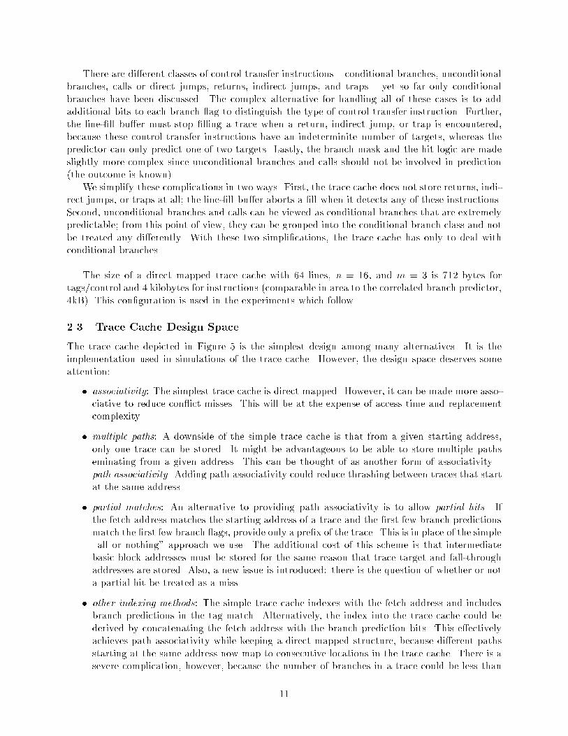
There are di�erent classes of control transfer instructions � conditional branches� unconditionalbranches� calls or direct jumps� returns� indirect jumps� and traps � yet so far only conditionalbranches have been discussed� The complex alternative for handling all of these cases is to addadditional bits to each branch �ag to distinguish the type of control transfer instruction� Further�the line��ll bu�er must stop �lling a trace when a return� indirect jump� or trap is encountered�because these control transfer instructions have an indeterminite number of targets� whereas thepredictor can only predict one of two targets� Lastly� the branch mask and the hit logic are madeslightly more complex since unconditional branches and calls should not be involved in prediction�the outcome is known��We simplify these complications in two ways� First� the trace cache does not store returns� indi�
rect jumps� or traps at all� the line��ll bu�er aborts a �ll when it detects any of these instructions�Second� unconditional branches and calls can be viewed as conditional branches that are extremelypredictable� from this point of view� they can be grouped into the conditional branch class and notbe treated any di�erently� With these two simpli�cations� the trace cache has only to deal withconditional branches�
The size of a direct mapped trace cache with �� lines� n � ��� and m � � is ��� bytes fortags�control and � kilobytes for instructions �comparable in area to the correlated branch predictor��kB�� This con�guration is used in the experiments which follow�
��� Trace Cache Design Space
The trace cache depicted in Figure � is the simplest design among many alternatives� It is theimplementation used in simulations of the trace cache� However� the design space deserves someattention
� associativity The simplest trace cache is direct mapped� However� it can be made more asso�ciative to reduce con�ict misses� This will be at the expense of access time and replacementcomplexity�
� multiple paths A downside of the simple trace cache is that from a given starting address�only one trace can be stored� It might be advantageous to be able to store multiple pathseminating from a given address� This can be thought of as another form of associativity �path associativity� Adding path associativity could reduce thrashing between traces that startat the same address�
� partial matches An alternative to providing path associativity is to allow partial hits� Ifthe fetch address matches the starting address of a trace and the �rst few branch predictionsmatch the �rst few branch �ags� provide only a pre�x of the trace� This is in place of the simple�all or nothing approach we use� The additional cost of this scheme is that intermediatebasic block addresses must be stored for the same reason that trace target and fall�throughaddresses are stored� Also� a new issue is introduced there is the question of whether or nota partial hit be treated as a miss�
� other indexing methods The simple trace cache indexes with the fetch address and includesbranch predictions in the tag match� Alternatively� the index into the trace cache could bederived by concatenating the fetch address with the branch prediction bits� This e�ectivelyachieves path associativity while keeping a direct mapped structure� because di�erent pathsstarting at the same address now map to consecutive locations in the trace cache� There is asevere complication� however� because the number of branches in a trace could be less than
��

m � �� This implies the index should not use all branch prediction bits to access the tracecache� yet this is not known in advance� A possible solution is to write the same trace to twoor more consecutive locations� so that either location gives a hit�
� �ll issues While the line��ll bu�er is collecting a new trace� the trace cache continues to beaccessed by the fetch unit� This means a miss could occur in the midst of handling a previousmiss� The design options in order of increasing complexity are ignore any new misses� delayservicing new misses until the line��ll bu�er is free� or provide multiple line��ll bu�ers tosupport concurrent misses� Another issue is whether to �ll the trace cache with speculativetraces or to wait for branch outcomes before committing a trace to the cache�
� judicious trace selection There are likely to be traces that are committed but never reused�These traces may displace useful traces� causing needless misses� To improve trace cache hitrates� the design could use a small bu�er to store recent traces� a trace in this bu�er is onlycommitted to the trace cache after one or more hits to that trace�
� victim trace cache An alternative to judicious trace selection is to use a victim cache ��� �A victim trace cache may keep valuable traces from being permanently displaced by uselesstraces�
��

� Other High Bandwidth Fetch Mechanisms
In this section we analyze the organization of two previously proposed fetch mechanisms aimed atfetching and aligning multiple noncontiguous basic blocks each cycle� The analysis compares thesemechanisms against the trace cache� with latency being the key point for comparison�
��� Branch Address Cache
The branch address cache fetch mechanism proposed by Yeh� Marr� and Patt �� is shown in Figure ��There are four primary components ��� a branch address cache �BAC�� ��� a multiple branchpredictor� ��� an interleaved instruction cache� and ��� an interchange and alignment network� TheBAC extends the BTB to multiple branches by storing a tree of target and fall�through addressesas depicted in Figure �� The depth of the tree depends on the number of branches predicted percycle�
1st branch
2nd branch
3rd branch
A
F GED
B C
H I J K L M N O
T
T
T
NT
Figure � Each BAC entry stores a portion of the control �ow graph�
In Figure �� light grey boxes represent non�control transfer instructions and dark grey boxesrepresent branches� the �elds in the BAC correspond to the tree in Figure �� as indicated bythe address labels A through O� The diagram depicts the two�stage nature of the design� In the�rst stage� an entry containing up to �� basic block addresses is read from the BAC� From theseaddresses� up to � basic block addresses corresponding to the predicted path are selected� In thisexample� the next � branches are all predicted taken� corresponding to the sequence of basic blocksfC�G�Og� In the second stage� the instruction cache reads the three basic blocks indicated byaddresses from the BAC in parallel from its multiple banks� Since the basic blocks may be placedarbitrarily into the cache banks� they must pass through an alignment network to align them intodynamic program order and merge them into the instruction latch�The two stages in this design are pipelined� During the second stage� while basic blocks fC�G�Og
are being fetched from the instruction cache� the BAC begins a new cycle using address O as itsindex� In general� the last basic block address indexing into the instruction cache is also the indexinto the BAC�If an address misses in the BAC� an entry is allocated for the portion of the control �ow graph
which begins at that address� Branch target and fall�through addresses are �lled in the entry aspaths through the tree are traversed� an entry may contain holes corresponding to branches whichhave not yet been encountered�Though conceptually the design has two pipeline stages� possibly one or more additional pipeline
stages are implied by having the complicated alignment network� The alignment network must ���
��

interchange the cache lines from numerous banks �with more than two banks� the permutations growquickly�� and ��� collapse the basic blocks together� eliminating unused intervening instructions�Though not discussed in �� � logic like the collapsing bu�er �� discussed in the next section will beneeded to do this�
ALIGNMENT and MASKING NETWORK
bank address latches
instruction latchOGC
Interleaved Instruction Cache
O
G
C
C G O3 predictions
14 addresses
select logic
tag CA B
A
N O
(e.g. 111)
Branch Address Cache
Predictor
F
Fill Buffer
G L M
Control Logicfill buffer
Address Caclculation Logic
Seco
nd S
tage
Firs
t Sta
ge
Figure � The BAC approach to instruction fetching�
��

��� Collapsing Bu�er
The instruction fetch mechanism proposed by Conte� Mills� Menezes� Patel �� is illustrated inFigure �� It is composed of ��� an interleaved instruction cache� ��� an interleaved branch targetbu�er �BTB�� ��� a multiple branch predictor� ��� special logic after the BTB� and ��� an interchangeand alignment network featuring a collapsing bu�er�
C
BA
BA
CBA
COLLAPSING BUFFER
16-way Interleaved
BRANCH TARGET BUFFER
C
LOGICBTB
fetchaddress
targetaddress
MULTIPLE
BRANCH
PREDICTOR
valid instructionsbit vector
intrablockbranch
interblockbranch
2-Way InterleavedInstruction Cache
to decoder
3
"111"
1st: 00111000111110002nd: 0000000111111000
Line Size = 16 InstructionsLine Size = 16 Instructions
INTERCHANGE/MASKING NETWORK
== C
Figure � The instruction fetch mechanism proposed by Conte et al �� �
The hardware is similar to the core fetch unit of the trace cache �described in Section ��� buthas two important distinctions� First� the BTB logic is capable of detecting intrablock branches� short hops within a cache line� Second� a single fetch goes through two BTB accesses� As willbe described below� this allows fetching beyond one taken interblock branch � a branch out of thecache line� In both cases� the collapsing bu�er uses control information generated by the BTB logicto merge noncontiguous basic blocks�Figure � illustrates how three noncontiguous basic blocks labelled A� B� and C are fetched� The
��

fetch address A accesses the interleaved BTB� The BTB indicates that there are two branches inthe cache line� one at the instruction � with target address B� the other at the instruction �� withtarget address C� Based on this branch information and branch predictions from the predictor� theBTB logic indicates which instructions in the fetched line are valid and produces the next basicblock address� C�The initial BTB lookup produces ��� a bit vector indicating the predicted valid instructions in
the cache line �instructions from basic blocks A and B�� and ��� the predicted target address C ofbasic block B� The fetch address A and target address C are then used to fetch two nonconsecutivecache lines from the interleaved instruction cache� This can be done only if the cache lines are indi�erent banks� In parallel with this instruction cache access� the BTB is accessed again� usingthe target address C� This second� serialized lookup determines which instructions are valid in thesecond cache line and produces the next fetch address �the predicted successor of basic block C��When the two cache lines have been read from the cache� they pass through masking and
interchange logic and the collapsing bu�er �which merges the instructions�� all controlled by bitvectors produced by the two passes through the BTB� After this step� the properly ordered andmerged instructions are captured in the instruction latches to be fed to the decoders�This scheme has several disadvantages� First� the fetch line and successor line must reside in
di�erent cache banks� Bank con�icts can be reduced by adding more banks� but this requires amore complicated� higher latency interchange switch� Second� this scheme does not scale well forinterblock branches� supporting additional interblock branches requires as many additional BTBaccesses� all serialized� Third� the BTB logic requires a serial chain of n address comparators todetect intrablock branches� where n is the number of BTB banks� Most seriously� however� is thatthis fetch mechanism adds a signi�cant amount of logic both before and after the instruction cache�The instruction fetch pipeline is likely to have three stages� as depicted in Figure � ��� initial BTBlookup and BTB logic� ��� instruction cache access and second BTB lookup� and ��� interchangeswitch� masking� and collapsing bu�er� Because the BTB is used in both the �rst and second stages�a new fetch cycle cannot be initiated until the third stage unless the BTB is dual�ported and theBTB logic is duplicated�The collapsing bu�er takes only a single stage if implemented as a bus�based crossbar �� � Note
that the collapsing bu�er is dependent on control information from the second BTB lookup� socontrol fanout logic from the third stage cannot be brought up into the second stage� i�e� there istruly a third stage�
ICACHE
BTB 2BTB 1 CB
Figure � Stages in the CB approach�
��

� Simulation Methodology
��� Processor Model
Our simulation model follows the basic structure shown in Figure � � a fetch engine and an executeengine decoupled via instruction issue bu�ers� Various fetch engines � trace cache� branch addresscache� and collapsing bu�er � are modeled in detail� The processor execution part of the modelis constrained only by true data dependences� We assume unlimited hardware resources � anyinstructions in the instruction bu�ers that have their data available may issue� This is done toplace as much demand on the fetch unit as any implementation will ever achieve� making instructionfetch the performance bottleneck whenever possible� In e�ect� unlimited register renaming and fulldynamic instruction issue are assumed� Loads and stores are assumed to have oracle addressdisambiguation � loads and stores wait for previous stores only if there is a true address con�ict�Also� the data cache always hits� The only hardware limitations imposed are the maximum sizeof the instruction bu�er and the degree of superscalar dispatch� In all simulations� the size of theinstruction bu�er is ���� useful instructions and the maximum fetch�dispatch bandwidth is ��instructions per cycle� In summary� the amount of ILP exploited is limited by � factors
� maximum fetchdispatch rate ��cycle
� maximum size of instruction window ����
� true data dependences in the program
� operation latencies
� performance of the fetch engine
It is the last factor that we are interested in and which will vary between simulations�The instruction pipeline is composed of � phases fetch� dispatch� issue� and execution� The
latency of the fetch phase is varied according to implementation� and the dispatch latency is �xedat � cycle� If all operands are available at or immediately after dispatch� instruction issue takesonly � cycle� otherwise issue is delayed until operands arrive� Because of unlimited resources andunlimited register renaming� issue never stalls due to structural or register WAR�WAW hazards�After issue� execution takes a certain number of cycles based on the operation� Operation latenciesare shown in Table �� The minimum pipeline latency from fetch to completion is therefore � cycles�for a fetch unit latency of � cycle� no data dependence stalls� and a � cycle operation� The retirestage�s� of the pipeline are hidden due to unlimited result forwarding from the execute stage to theissue stage�
��� Workload
Six integer and six �oating point benchmarks from the SPEC suite were used to evaluate the per�formance of the various fetch mechanisms� The benchmarks were compiled on a Sun SPARCstation����� using �gcc �O� �static �fschedule�insns �fschedule�insns� for integer benchmarks and �f���O� �Bstatic �fast �cg�� for �oating point benchmarks� SPARC instruction traces were generatedusing the Quick Pro�ler and Tracer �QPT� ��� and then fed into the trace�driven processor simula�tor� Table � shows inputs for each of the benchmarks� Benchmarks were simulated for ��� millioninstructions�The foremost problem with trace�driven simulation is that incorrect speculative execution can�
not be simulated� since traces represent only the correct path of execution� This may lead to some
��

OPERATION LATENCIES �cycles�
Integer ALU Operations �
Loads �y
Stores �z
Control Transfer Instructions �
FP Add�Sub�Mult�Conv �
FP Div �����
FP Sqrt �����
all other FP ops �
y One cycle to compute address� one cycle to access the data cache�z One cycle to compute address� the rest of the write is hidden� store data can always be bypassed todependent loads when available�
Table � Operation execution latencies� Note that for loads and stores� data cache misses arenot simulated� Floating point latencies for the most common operations are similar to the MIPSR����� ��� �
error� For example� cache structures do not see the pollution e�ects caused by fetching and execut�ing instructions down the wrong path� Further� our execution engine does not see resource usagedue to incorrectly speculated instructions �however� because of unlimited resource assumptions inthe execution model� this latter factor will not produce performance much di�erent from simulationof incorrect speculation��
BENCHMARK input BENCHMARK input
eqntott int pri ��eqn doduc doducin
espresso bca�in tomcatv �internal�
compress in nasa� �internal�
gcc stmt�i mdljdp� mdlj��dat
xlisp li�input�lsp swm��� swm����in
sc loada� su�cor su�cor�in
Table � Benchmarks and their inputs�
��� Performance Metric
For measuring performance we use instructions completed per cycle �IPC�� which is a direct measureof performance and is almost certainly the measure that counts most� The harmonic mean is usedto average the performance of benchmarks�
��

� Results
Table � summarizes the trace cache �TC�� collapsing bu�er �CB�� and branch address cache �BAC�fetch unit parameters used in all experiments� In the sections which follow� results for the threehigh bandwidth implementations are compared� Previously� these methods could not be comparedbecause the studies used di�erent simulation environments �instruction sets� benchmarks� compilers�performance metrics� and di�erent hardware con�gurations �execution model� instruction cache�branch predictor� etc���As a base case for comparison� results are also presented for conventional instruction fetching�
The core fetch unit of the trace cache �described in Section ���� is used as the base case� We willcall the base case �sequential �SEQ�� since only sequential instructions can be fetched in a givencycle� To demonstrate the e�ect of branch throughput� two variations of SEQ are simulated SEQ��is limited to one basic block per cycle� and SEQ�� can fetch up to three contiguous basic blocks�Simulation parameters for SEQ are the same as those for TC in Table �� but with the trace cachenot present �and � or � branch predictions per cycle��
INSTRUCTION SUPPLY MECHANISMSIMULATION PARAMETER TC CB BAC
instruction fetch limit �� instructions per cycle
BHR �� bitsMultiple Branch PHT ��� ��bit counters �� KB storage�Predictor pred�cycle up to � predictions each cycle
size ��� KBassociativity direct mapped
Instruction Cache line size �� instructions �� instructions � instructionsinterleave factor ��way ��way ��waymiss penalty �� cycles
Return Address Stack depth unlimited
size ���� entries ���� entriesBranch Target Bu�er associativity direct mapped direct mapped n�a
interleave factor ���way ���way
size �� entriesTrace Cache associativity direct mapped n�a
line size �� instructions concurrent �lls �
size ���� entriesBranch Address Cache associativity n�a direct mapped
concurrent �lls �
Table � Fetch unit con�gurations�
The simulators only di�er in fetch unit�speci�c hardware� Because of the fundamental di�er�ences between fetch units� it is di�cult to maintain an area budget over all the schemes� Therefore�area di�erences must always be kept in mind when comparing the results� Here we comment brie�yabout area comparisons
� The trace cache used adds under � kB of additional SRAM storage to the core fetch unit�
��

SEQ��� The SRAM is assumed to have � read port and � write port�
� Super�cially� the CB fetch unit di�ers from SEQ only in datapath after the instruction cache�However� the BTB must be dual�ported to support pipelining the CB fetch unit� In the worstcase �replicating cells�� a dual�ported BTB has twice the area� The BTB used throughouttakes up about � kB of SRAM storage� if we assume ��� to � times that for dual�porting� addanother ��� to � kB of storage for the CB fetch unit�
� A large BAC ����� entries� is used in the experiments because the BAC must perform thefunctions of both the TC and BTB� The BTB is a particularly important resource because itgets most of the base performance� A rough area estimate for the BAC is about �� kB ����bits per entry �� ��
The results are split into two sets� The �rst set assumes all fetch units have a latency of �cycle� in order to demonstrate each mechanism�s ability to deliver bandwidth performance� Thesecond set shows what happens when the extra pipe stages implied by CB and BAC are actuallysimulated�
��� Single�Cycle Fetch Latency
The �rst set of results� Table � and corresponding graphs in Figures �� and ��� assumes a fetchunit latency of � cycle for all schemes� This is done to isolate the ability of the fetch mechanismsto supply instruction bandwidth�
Benchmark SEQ�� SEQ�� BAC CB TC
eqntott ���� ���� ���� ���� ����
espresso ���� ���� ���� ���� ����
xlisp ���� ���� ���� ���� ����
gcc ���� ���� ���� ���� ����
sc ���� ���� ���� ���� ����
compress ���� ���� ���� ���� ����
doduc ���� ���� ���� ���� ����
tomcatv ���� ���� ���� ���� ����
nasa� ���� ���� ���� ���� ����
mdljdp� ���� ���� ���� ���� ����
swm��� ���� ���� ���� ���� ����
su�cor ���� ���� ���� ���� ����
Table � Performance of instruction fetch mechanisms� assuming unit fetch latency for all�
The �rst observation is that SEQ�� gives a substantial performance boost over SEQ��� The graphin Figure �� shows that fetching past multiple not�taken branches each cycle yields performanceimprovement above �� for all of the integer benchmarks� Half of the integer benchmarks show a��� or better performance improvement� Only two of the �oating point benchmarks show similarimprovement�The second observation is that for integer benchmarks� fetching past taken branches is a big
win� Adding the TC function to the SEQ�� mechanism yields as much performance improvement
��

IPC for the Various Fetch Mechanisms, Single-Cycle Latency
1.5
2
2.5
3
3.5
4
4.5
5
5.5
eqntott espresso xlisp gcc sc compress
integer benchmark
IPC
SEQ.1
SEQ.3
BAC
CB
TC
Figure �� IPC for the various fetch mechanisms� assuming a fetch unit latency of � cycle for alldesigns� �integer benchmarks�
as extending SEQ�� to multiple not�taken branches per cycle� and in some cases signi�cantly moreimprovement� Somewhat surprisingly� half of the �oating point benchmarks see substantial perfor�mance improvement ���� or more� with the TC�The graph in Figure �� shows the performance improvement that BAC� CB� and TC yield over
SEQ�� �SEQ�� is used as the base instead of SEQ�� because it is aggressive� yet not much morecomplex than SEQ���� One might expect that under the single�cycle fetch latency assumption� thethree approaches would perform similarly� However� TC enjoys a noticeable lead over CB� Thisis most likely because the original collapsing bu�er was not designed to handle backward takenintrablock branches �� � whereas the TC can handle any arbitrary trace� The BAC performs worstof the three� and in some cases even performs below SEQ�� � particularly in �oating point� Thereare two explanations for this behavior
� Instruction cache bank con�icts are the primary performance loss for BAC� Table � showsthat BAC is comparable to TC if bank con�icts are ignored� again assuming single�cycle fetchlatency for BAC�
� The BAC treats basic blocks as atomic units� As a result� a BAC entry will provide only asmany basic block addresses as will �t within the �� instruction fetch limit� The consequenceis that given hits in both the TC and BAC� the BAC can never supply more instructions thanthe TC� This situation can be remedied by having a wider fetch datapath than the dispatchdatapath� which amounts to prefetching�
��

IPC for the Various Fetch Mechanisms, Single-Cycle Latency
3
5
7
9
11
13
doduc tomcatv nasa7 mdljdp2 swm256 su2cor
floating point benchmark
IPC
SEQ.1
SEQ.3
BAC
CB
TC
Figure �� IPC for the various fetch mechanisms� assuming a fetch unit latency of � cycle for alldesigns� ��oating point benchmarks�
Performance Improvement of SEQ.3 over SEQ.1
0.0%
5.0%
10.0%
15.0%
20.0%
25.0%
30.0%
eqnt
ott
espr
esso
xlis
p
gcc sc
com
pres
s
dodu
c
tom
catv
nasa
7
mdl
jdp2
swm
256
su2c
or
benchmark
% im
pro
vem
ent
in IP
C
Figure �� Performance improvement of SEQ�� over SEQ���
��

Performance Improvement over SEQ.3, Single-Cycle Latency
-10.0%
-5.0%
0.0%
5.0%
10.0%
15.0%
20.0%
25.0%
30.0%eq
ntot
t
espr
esso
xlis
p
gcc sc
com
pres
s
dodu
c
tom
catv
nasa
7
mdl
jdp2
swm
256
su2c
or
benchmark
% im
pro
vem
ent
in IP
C
BAC
CB
TC
Figure �� Performance improvement of BAC� CB� and TC over SEQ��� assuming a fetch unitlatency of � cycle for all designs�
Benchmark BAC �con�icts� BAC �no con�icts� TC
eqntott ���� ���� ����
espresso ���� ���� ����
xlisp ���� ���� ����
gcc ���� ���� ����
sc ���� ���� ����
compress ���� ���� ����
Table � The performance of BAC is severely limited by instruction cache bank con�icts� This tableshows that the performance of BAC is comparable to TC if bank con�icts are ignored� assumingunit fetch latency�
��
��� The E�ect of Latency
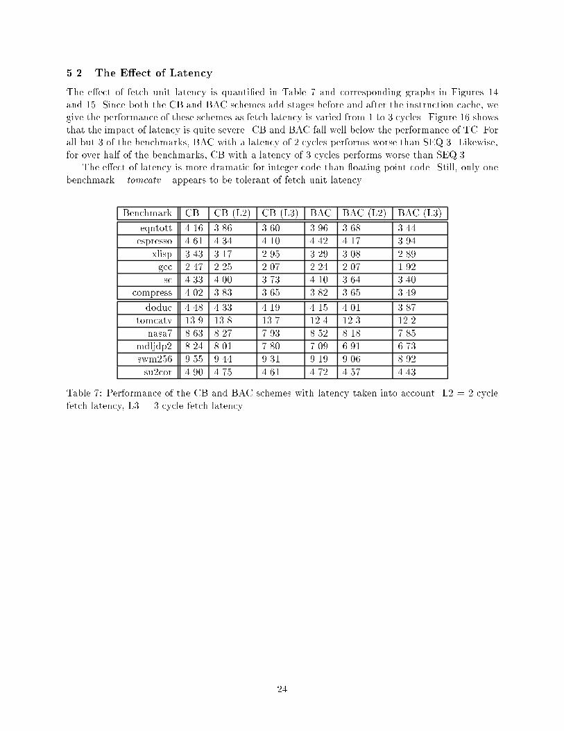
The e�ect of fetch unit latency is quanti�ed in Table � and corresponding graphs in Figures ��and ��� Since both the CB and BAC schemes add stages before and after the instruction cache� wegive the performance of these schemes as fetch latency is varied from � to � cycles� Figure �� showsthat the impact of latency is quite severe� CB and BAC fall well below the performance of TC� Forall but � of the benchmarks� BAC with a latency of � cycles performs worse than SEQ��� Likewise�for over half of the benchmarks� CB with a latency of � cycles performs worse than SEQ���The e�ect of latency is more dramatic for integer code than �oating point code� Still� only one
benchmark � tomcatv � appears to be tolerant of fetch unit latency�
Benchmark CB CB �L�� CB �L�� BAC BAC �L�� BAC �L��
eqntott ���� ���� ���� ���� ���� ����
espresso ���� ���� ���� ���� ���� ����
xlisp ���� ���� ���� ���� ���� ����
gcc ���� ���� ���� ���� ���� ����
sc ���� ���� ���� ���� ���� ����
compress ���� ���� ���� ���� ���� ����
doduc ���� ���� ���� ���� ���� ����
tomcatv ���� ���� ���� ���� ���� ����
nasa� ���� ���� ���� ���� ���� ����
mdljdp� ���� ���� ���� ���� ���� ����
swm��� ���� ���� ���� ���� ���� ����
su�cor ���� ���� ���� ���� ���� ����
Table � Performance of the CB and BAC schemes with latency taken into account� L� � � cyclefetch latency� L� � � cycle fetch latency�
��

Performance of Various Fetch Mechanisms, Non-unit Latency
1.5
2
2.5
3
3.5
4
4.5
5
5.5
eqntott espresso xlisp gcc sc compress
integer benchmark
IPC
SEQ.1
SEQ.3
BAC
BAC (L2)
BAC (L3)
CB
CB (L2)
CB (L3)
TC
Figure �� IPC for the various fetch mechanisms� using realistic latencies for CB and BAC� L� andL� stand for � cycle and � cycle latency� respectively� �integer benchmarks�
Performance of Various Fetch Mechanisms, Non-unit Latency
3
5
7
9
11
13
doduc tomcatv nasa7 mdljdp2 swm256 su2cor
floating point benchmark
IPC
SEQ.1
SEQ.3
BAC
BAC (L2)
BAC (L3)
CB
CB (L2)
CB (L3)
TC
Figure �� IPC for the various fetch mechanisms� using realistic latencies for CB and BAC� L� andL� stand for � cycle and � cycle latency� respectively� ��oating point benchmarks�
��

Performance Improvement over SEQ.3, Non-unit Latency
-20.0%
-15.0%
-10.0%
-5.0%
0.0%
5.0%
10.0%
15.0%
20.0%
25.0%
30.0%
eqnt
ott
espr
esso
xlis
p
gcc sc
com
pres
s
dodu
c
tom
catv
nasa
7
mdl
jdp2
swm
256
su2c
or
benchmark
% im
pro
vem
ent
in IP
C
BAC (L2)
BAC (L3)
CB (L2)
CB (L3)
TC
Figure �� Performance improvement of BAC� CB� and TC over SEQ��� using realistic latencies forCB and BAC� L� and L� stand for � cycle and � cycle latency� respectively�
��
��� Trace Cache E�ectiveness
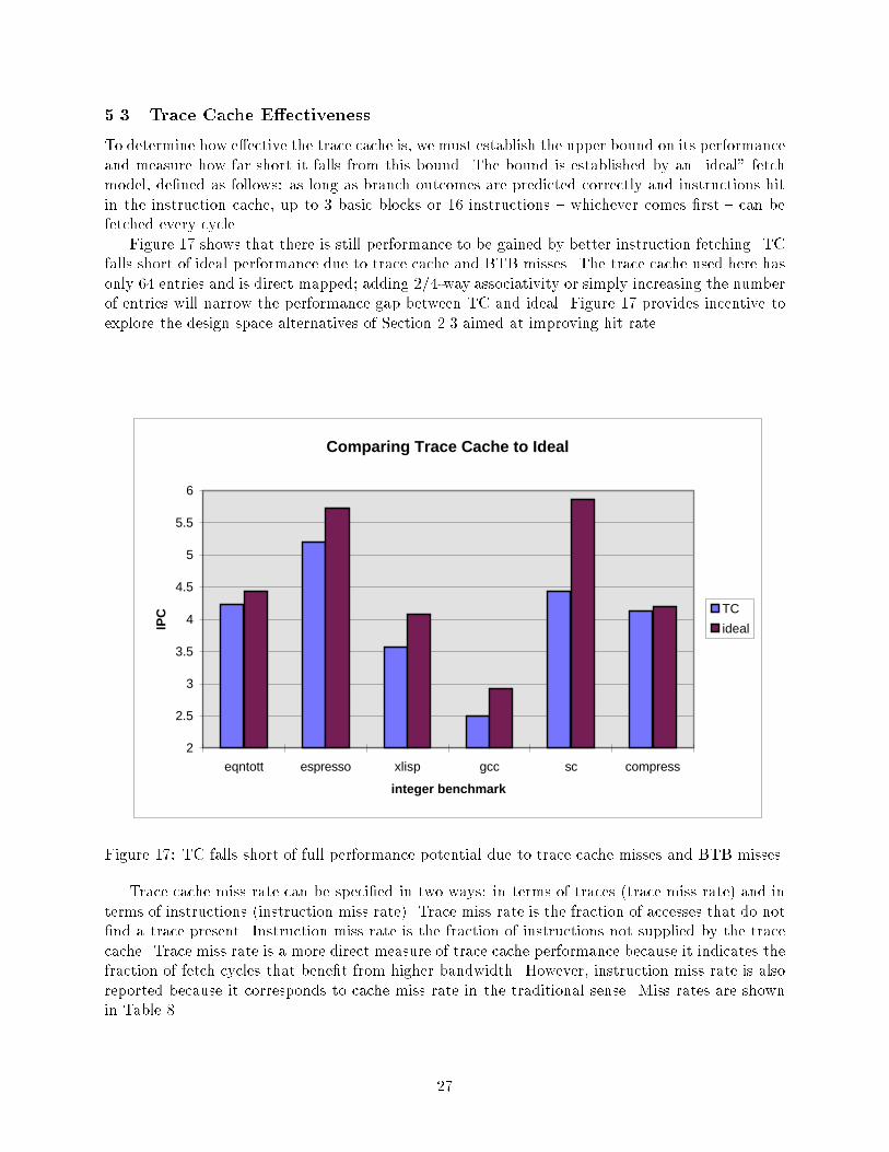
To determine how e�ective the trace cache is� we must establish the upper bound on its performanceand measure how far short it falls from this bound� The bound is established by an �ideal fetchmodel� de�ned as follows as long as branch outcomes are predicted correctly and instructions hitin the instruction cache� up to � basic blocks or �� instructions � whichever comes �rst � can befetched every cycle�Figure �� shows that there is still performance to be gained by better instruction fetching� TC
falls short of ideal performance due to trace cache and BTB misses� The trace cache used here hasonly �� entries and is direct mapped� adding ����way associativity or simply increasing the numberof entries will narrow the performance gap between TC and ideal� Figure �� provides incentive toexplore the design space alternatives of Section ��� aimed at improving hit rate�
Comparing Trace Cache to Ideal
2
2.5
3
3.5
4
4.5
5
5.5
6
eqntott espresso xlisp gcc sc compress
integer benchmark
IPC TC
ideal
Figure �� TC falls short of full performance potential due to trace cache misses and BTB misses�
Trace cache miss rate can be speci�ed in two ways in terms of traces �trace miss rate� and interms of instructions �instruction miss rate�� Trace miss rate is the fraction of accesses that do not�nd a trace present� Instruction miss rate is the fraction of instructions not supplied by the tracecache� Trace miss rate is a more direct measure of trace cache performance because it indicates thefraction of fetch cycles that bene�t from higher bandwidth� However� instruction miss rate is alsoreported because it corresponds to cache miss rate in the traditional sense� Miss rates are shownin Table ��
��

Benchmark trace miss rate instruction miss rate
eqntott ����� �����
espresso ����� �����
xlisp ����� �����
gcc ����� �����
sc ����� �����
compress ����� �����
doduc ����� �����
tomcatv ����� �����
nasa� ����� �����
mdljdp� ����� �����
swm��� ����� �����
su�cor ����� �����
Table � Trace miss rate and instruction miss rate for a �� entry direct mapped trace cache�
��

� Conclusions
Trends in processor organization � wider dispatch�issue� larger instruction windows� and deeperspeculation � expose new instruction fetch performance issues� These are branch throughput�noncontiguous instruction alignment� and fetch unit latency�Experiments with real implementations yield the following results
� For integer code� being able to fetch past multiple not�taken branches improves performanceon average by ��� over a fetch unit that is limited to � branch prediction per cycle� For�oating point� the average performance improvement is ���
� For integer code� being able to fetch past multiple taken branches improves performance onaverage by ��� over a fetch unit that can only fetch contiguous instructions �this result is forthe trace cache implementation�� For �oating point� the average performance improvementis ���
� The trace cache consistently performs better than either of the other high bandwidth fetchmechanisms studied � collapsing bu�er and branch address cache � even if unit fetch latency isassumed across all three� The primary reasons for this are ��� the original CB design does nothandle backward taken intrablock branches and ��� the BAC design su�ers from instructioncache bank con�icts�
� Simulations with more realistic latencies for the CB and BAC designs �based on stages beforeand after the instruction cache� clearly show the advantage of using a low latency approach�Their performance falls well below that of the trace cache� and in some cases a low latency�lower bandwidth fetch unit does better�
The combined e�ect of multiple branches per cycle and noncontiguous instruction fetching is anaverage improvement of ��� for integer benchmarks and ��� for �oating point benchmarks� usingthe trace cache�
While a small trace cache performs well� comparison with the �ideal noncontiguous instructionfetch model shows the potential for even higher performance � additional improvement in the rangeof �� to ���� This experiment motivates investigation of larger and�or more complex trace cachedesigns� such as path associativity� partial matches� judicious trace selection� and victim tracecaches�
In conclusion� it is important to design fetch units capable of fetching past multiple� possiblytaken branches each cycle� However� this additional bandwidth performance should not be achievedat the expense of longer fetch unit latency� The trace cache is successful in satisfying both of theserequirements�
� Acknowledgements
This work was supported in part by NSF Grant MIP�������� and by the U�S� Army IntelligenceCenter and Fort Huachuca under Contract DABT������C����� and ARPA order no� D���� Theviews and conclusions contained herein are those of the authors and should not be interpreted asnecessarily representing the o�cial policies or endorsements� either expressed or implied� of theU�S� Army Intelligence Center and Fort Huachuca� or the U�S� Government�Eric Rotenberg is funded by a Graduate Fellowship from IBM�
��
References
�� T� Conte� et al� � �Optimization of Instruction Fetch Mechanisms for High Issue Rates� Pro�ceedings of the International Symposium on Computer Architecture� June �����
�� T�Y Yeh� D� Marr and Y� Patt� �Increasing the Instruction Fetch Rate via Multiple BranchPrediction and a Branch Address Cache� Proceedings of the �th ACM International Conferenceon Supercomputing� July �����
�� M� Franklin and M� Smotherman� �A Fill�Unit Approach to Multiple Instruction Issue� Pro�ceedings of the ��th Annual International Symposium on Microarchitecture� December �����
�� S� Dutta and M� Franklin� �Control Flow Prediction with Tree�Like Subgraphs for SuperscalarProcessors� to appear Micro���� Nov� �����
�� J� Lee and A� J� Smith� �Branch Prediction Strategies and Branch Target Bu�er Design� IEEEComputer� January �����
�� J� Losq� �Generalized History Table for Branch Prediction� IBM Technical Disclosure Bulletin�June �����
�� G� F� Grohoski� �Machine Organization of the IBM RISC System����� processor� IBM Journalof Research and Development� January �����
�� S�T Pan� K� So� and J� T� Rahmeh� �Improving the Accuracy of Dynamic Branch PredictionUsing Branch Correlation� Proceedings of the �th International Conference on ArchitecturalSupport for Programming Languages and Operating Systems� October �����
�� T�Y Yeh and Y� N� Patt� �Alternative Implementations of Two�Level Adaptive Branch Predic�tion� Proceedings of the ��th International Symposium on Computer Architecture� May �����
��� T�Y Yeh� �Two�level Adaptive Branch Prediction and Instruction Fetch Mechanisms for High�Performance Superscalar Processors� PhD Thesis� Department of Electrical Engineering andComputer Science� University of Michigan� �����
��� T�Y Yeh and Y� N� Patt� �A Comprehensive Instruction Fetch Mechanism for a ProcessorSupporting Speculative Execution� �
��� E� Hao� P� Chang and Y� Patt� �The E�ect of Speculatively Updating Branch History onBranch Prediction Accuracy� Revisited� Proceedings of the ��th annual International Symposiumon Microarchitecture� December �����
��� D� Kaeli and P� Emma� �Branch History Table Prediction of Moving Target Branches Due toSubroutine Returns� Proceedings of the ��th International Symposium on Computer Architec�ture� May �����
��� D� Wall� �Limits of Instruction�Level Parallelism� International Conference on ArchitecturalSupport for Programming Languages and Operating Systems� �����
��� L� Gwennap� �MIPS R����� Uses Decoupled Architecture� Microprocessor Report� October�����
��� J� Larus� �E�cient Program Tracing� IEEE Computer� May �����
��

��� S� Melvin� M� Shebanow and Y� Patt� Hardware Support for Large Atomic Units in Dy�namically Scheduled Machines� Proceedings of the ��st Annual International Symposium onMicroarchitecture� December �����
��� J� E� Smith� �A Study of Branch Prediction Strategies� Proceedings of the �th Symposium oncomputer Architecture� May �����
��� J� E� Smith and G� S� Sohi� �The Microarchitecture of Superscalar Processors� ProceedingsIEEE� December �����
��� N� Jouppi� �Improving Direct�Mapped Cache Performance by the Addition of a Small Fully�Associative Cache and Prefetch Bu�ers� Proceedings of the ��th International Symposium onComputer Architecture� May �����
��

A Logic Implementation Issues
This appendix serves as a repository for many of the issues that we encountered in our study ofthe various high bandwidth instruction fetch mechanisms� There is no signi�cance to the orderthat things are presented� except that several subsections depend on the BTB description� whichis presented �rst� Also� a given section may be relevant to one or more di�erent fetch mechanisms�
A�� Concerning the Branch Target Bu�er
The branch target bu�er di�ers from its original design in that it must locate branches within ablock of instructions� The conventional branch target bu�er takes a single word address and deter�mines if there is a branch at that address� a scheme originally intended for single issue processors�Extending the branch target bu�er to detect multiple branches in a block of instructions is fairlystraightforward� Conte et al� �� propose an interleaved branch target bu�er where the number ofbanks is equal to the number of instructions in a cache line� In this way� all locations in the fetchedcache line can be checked for branches in parallel� �The address of the �rst instruction in the cacheline is used to index the �rst bank� the address of the second instruction indexes the second bank�and so on��Barring misses� the branch target bu�er provides all of the branch information contained in
a cache line� This information must be combined with multiple branch predictions to determinetwo things which instructions in the fetched line are valid and what is the next fetch address�Matching predictions to their intended branches requires special logic after the branch target bu�er�Conceptually this logic scans the branch information from the �rst bank to the last bank countingbranches� This counting has an inherent ripple e�ect which is nontrivial for larger cache lines� Thelogic diagram in Figure �� shows a possible implementation where banks are counted in groups offour to reduce the amount of ripple� If four is not su�cient� even more �lookahead can be used�
We now present a detailed implementation of the BTB logic� The purpose of this logic is tocombine multiple branch predictions with branch information from the BTB to determine whichinstructions in the fetched cache line are valid and to produce the next fetch address�The implementation assumes a cache line size of �� instructions and � branch predictions per
cycle� The following notation and signals are used in expressions and logic diagrams
� x BTB bank number� also instruction position in the cache line� x ranges from � to ���
� hitx Bank x of the BTB indicates a hit� In other words� there is a branch at instructionposition x of the cache line�
� ADDR��� Bits � through � of the fetch address point to the �rst valid instruction in thecache line�
� bx If set� there is a valid branch at instruction position x in the cache line�
� onex If set� there is at least one valid branch preceding the instruction at position x�
� twox If set� there are at least two valid branches preceding the instruction at position x�
� threex If set� there are at least three valid branches preceding the instruction at position x�
� p� First branch prediction�
� p� Second branch prediction�
��

� p� Third branch prediction�
� Mx Mask bit for the instruction at position x in the cache line�
� SELx If this signal is set� the target address from bank x of the BTB is used as the nextfetch address�
The outputs of the logic are a bit vector indicating valid instructions and the next fetch address�The bit vector can be derived from the mask bits Mx� If there is a taken branch� the next fetchaddress is selected using the SELx signals� Here are the necessary expressions
bx � hitx�x � ADDR�������
Mx � �p�onex � p�twox � threex� � �x � ADDR�������
SELx � bx�onexp� � onextwoxp�p� � twoxthreexp�p�p�����
Most of the complexity is in computing onex� twox� and threex for all x� Essentially this involvescounting the number of valid branches from the leftmost bank to the rightmost bank� The ripplee�ect introduces too long a delay if counting proceeds one bank at a time� Figure �� shows how� banks can be grouped together for counting branches� analogous to carry lookahead logic� Thediagram shows how the ripple path �shaded region� sees only � additional gate levels every � banks�
��

bA
bB
Cb
Db
bB
bA+
bA Cb
bA Db
bAb
B
bB Cb
bB Db
Cb
Db
bAb
B Db
bAb
B Cb
bA Cb
Db
bB Cb
Db
Dbb
Cb
Bb
A++ +
Cbb
Bb
A+ +
threeA
twoA
oneA
oneB
threeB
twoB
oneC
twoC
threeC
twoD
threeD
oneD
twoOUT
threeOUT
oneOUT
oneIN
twoIN
threeIN
Figure��Countingthenumberofbrancheswithinagroupof�BTBbanks�Theshadedregion
highlightsthecritical
path�Ifthereare��instru
ctionsinacach
eline�andhence��BTBbanks�
�oftheselogicblocksare
daisy
�chainedtogeth
er���

A�� Concerning the Multiple Branch Predictor
Predicting the next sequence of basic blocks to be fetched requires predicting the outcomes ofmultiple intervening branches� The predictor must also be highly accurate so that the fetch unitcan speculate past many branches to form a large� accurate window of instructions for the executionengine� The multiple branch predictor used throughout this paper is that proposed by Yeh et al��� � Before describing the multiple branch predictor� it is necessary to brie�y review the singlebranch predictor on which it is based � the correlation predictor �� �The correlation predictor is shown in Figure ��� Correlation prediction uses the fact that the
outcome of a branch tends to be in�uenced by the outcomes of branches preceding it� It is oneof nine Two�level Adaptive Branch Prediction schemes �� all of which use two levels of historyto achieve high accuracy� The global branch history register �BHR� and the pattern history table�PHT� re�ect the two levels of history� A BHR k bits in length keeps a record of the outcomes ofthe last k branches� As new branches are encountered� their outcomes are shifted into the leastsigni�cant bit of the BHR� The PHT is a table of �k ��bit counters� one counter for each possiblepattern in the BHR� To predict the next branch� the BHR is used to index the PHT and a predictionis made based on the value of the corresponding PHT entry� In summary� the current predictiondepends on ��� the pattern of k preceding branches �the BHR�� and ��� the behavior of the branchthe last few times that pattern was encountered ���bit counter in the PHT�� When the outcome ofthe branch is known� it is used to update the same ��bit counter in the PHT �increment if taken�decrement if not taken��
k2 2-bit counters )(
shift inoutcomes
update counterwith outcome
k bits( )
single prediction
BRANCH HISTORY REGISTER
PATTERN HISTORY TABLE
Figure �� Correlation branch predictor�
Adapting the predictor for multiple branch predictions in one cycle requires changing both thephysical layout of the PHT and the way that the structures are updated� Conceptually the PHTmust be accessed multiple times� each time using successive shifts of the BHR as an index� It isimpractical to assume that multiple sequential accesses of the PHT can be made in a single cycle�Figure �� shows one possible implementation of the multiple branch predictor� There are two keyfeatures� First� the PHT has multiple read ports� one for each prediction� Second� the PHT isorganized such that a row of counters is read from each port� This is because the low order bitsof successive BHR indices are incomplete� These low order bits are only known after accessing thePHT� they feed a chain of multiplexors after the PHT to make �nal selections� Instead of updatingthe structures with branch outcomes� they must be speculatively updated with branch predictions�The BHR needs to shift in predictions because outcomes are simply unavailable� On the otherhand� speculatively updating the PHT is not a strict requirement� but from a heuristic standpointit is preferred over using stale history� In the event that a branch is mispredicted� the structures
��

should be repaired� Repairing the BHR is easily done by maintaining a second� �golden BHRwhich is updated with true branch outcomes� when a misprediction is detected� the golden BHRis loaded into the speculative BHR �rolling back the state�� Repairing entries in the PHT is morecomplex� it would be worthwhile to study the performance impact of not repairing PHT entries�
b
b13:2
b
13
b11:0
b0
b1
12:1
b0
b0
p0
p0
p
b
p0
p2
p1
1
1214 2-bit counters
212( )x 4 arrayarranged in
PATTERN HISTORY TABLE
GLOBAL HISTORY REGISTER
4:1 MUX
4:1 MUX
4:1 MUX
3 branch predictions
Figure �� Correlation branch predictor adapted for multiple branch predictions in a cycle�
When fetching from the instruction cache� correct handling of branches requires coordinationof the multiple branch predictor� branch target bu�er� and decode logic after the instruction latch�The following rules provide this coordination�
� If a branch misses in the branch target bu�er� the branch is automatically predicted nottaken� Since the branch is not detected until the decode stage �a cycle after fetching�� thesimplest alternative is to continue fetching sequentially� Even if the predictor predicted ataken branch� it is treated as not taken�
� The predictor itself does not know when to shift the BHR� and by how many bits� since ithas no knowledge of branches in the fetch stream� The problem is illustrated in Figure ���If all branches in the fetched line hit in the branch target bu�er� there is no problem � thenumber of bits to shift the BHR by is equal to the number of branches up to and includingthe �rst taken branch �Figure ���a��� However� if some branches do not hit in the branchtarget bu�er� the predictor will not know about them until it is too late �the decode stage��As a consequence� the BHR shifts less bits than required� and could fall behind the fetchunit in subsequent cycles �Figure ���b��� The solution is to always keep the BHR ahead�Figure ���c��� That is� if the predictor is capable of p predictions per cycle� it should stayup to p branches ahead of the fetch stream�
� The p predictions must be paired with their respective branches� Again� there is no problem ifall branches in the fetched line hit in the branch target bu�er � the �rst prediction goes to the�rst branch� the second prediction to the second branch� and so on �Figure ���a��� However� ifany branch misses in the branch target bu�er� predictions can get �skewed �Figure ���b�� �subsequent branches are assigned predictions intended for previous branches� There is no wayto avoid the problem� although recovery steps can be initiated in the decode stage� However�to be consistent with the �rst rule above� prediction �skew is simply tolerated�
��

� If more than p branches are detected in the fetched cache line� only instructions up to the pth
branch are supplied to the decoder� Fetching of instructions after the pth branch is delayeduntil the next cycle� This rule is imposed so that the predictor does not fall behind �itsthroughput is limited to p predictions per cycle��
Notice that predecode information in the instruction cache pertaining to the number and locationof branches can help the fetch mechanism a great deal�
hit in BTB =
0
1
3
4
2
7
8
9
11
13
12
10
15
14
labeled with
predictions (0 or 1)
fetched branches are
5
6
branch at this
position=
010predictions
1
0
number of bits to shift BHR by
number BTB hits 3
2
0
0
1
3
3
instructions in fetched line
001
�a� If all branches hitin the BTB� there isno problem determininghow many predictions aremade this cycle and there�fore how many bits to shiftthe BHR by�
0
3
1
2
6
7
8
5
4
12
9
14
prediction of thisbranch is delayed1 cycle since it missesin BTB
consequently,the predictionfor this branch
11
13
10
15 this cycleis unavailable
010predictions
0
number of bits to shift BHR by
number BTB hits
0
0
1
3
3
instructions in fetched line
1
1
1
100
�b� In this example the secondbranch is undetected in the �rst cy�cle since it misses in the BTB� Asa result� only � prediction is madein the �rst cycle and the BHR isshifted by only � bit� In the nextcycle� the decoder indicates thatthere was a second branch� and inaddition there are � new branches�This calls for new branch predic�tions� but the predictor can onlyprovide �� Not anticipating the sec�
ond branch in the �rst cycle causes
the predictor to fall behind�
1
0
3
5
6
2
8
4
13
7
10
15
14
predictions aremade for these 3branches in the 1st
9
only the 1st branchis known about
11
12
cycle, even though
010predictions
1
0
number of bits to shift BHR by
number BTB hits
0
0
1
3
instructions in fetched line
1
3
01-
2
�c� This example shows the pre�dictor keeping up to � branchesahead of fetching� to anticipate anybranches which are undetected un�til the decode stage� The predictormakes � predictions and shifts theBHR by � bits in the �rst cycle�even though only � branch is de�tected by the BTB� Only predic�tions are needed in the �rst cycle�so the third prediction is used inthe second cycle�
Figure �� Determining how many predictions to make and therefore how many bits to shift theBHR by�
��

b b b
hit hit hit
0 0 1
predictions: 0 0 1
�a� If all branches hit in the BTB� there is noproblem pairing up predictions with their intendedbranches�
0
b b b
hit hit
0
predictions: 0 0 1
�b� If a branch misses in the BTB� predictions maybe wrongly assigned to branches�
Figure �� Assigning predictions to branches and the problem of prediction �skew�
A�� Next PC MUX
The next fetch address is fed by a very large MUX� The following addresses are candidates for nextfetch address
� PC feedback � no change in the PC�
� Sequential PC � the PC incremented by the fetch bandwidth�
� Recover PC � feedback from the execution engine which redirects fetching�
� RAS PC � pop return address o� the return address stack if a return is detected�
� trace target � if a trace cache exists� and if it hits� this address is the target of trace�
� trace fall�through � if a trace cache exists� and if it hits� this address is the fall�through oftrace�
� BTB branch targets � if the BTB detects a taken branch� must select the appropriate branchtarget from � of �� banks�
By far the critical path exists in the MUX tree used to select � of the �� BTB target addresses�due to the complexity in generating the SEL���� select signals �refer to Section A���� The selectsignals are increasingly timing critical going from bit � to bit ��� The datapath in Figure �� re�ectsthis by skewing the MUX tree such that SEL����� goes through minimal logic� The expected criticalpath is labelled� though other critical paths may be exposed in the e�ort to reduce the primaryone�
��

TARGET ADDRESSES FROM BTB
fall-through @TC
target @TC
SEL15:12
SEL11:8
SEL7:4
SEL3:0MUX1
MUX2
MUX3
MUX4
PC
MUX5
MUX_OTHER
muxA
muxB
seq. PC
recover PCRAS
ExpectedCriticalPath
Figure �� The next PC MUX logic�
��

A�� Logic After the Instruction Cache
A���� Base Instruction Cache
The base instruction cache does not provide any support for fetching across taken branches� yet itis high performance in one respect it can always provide a full cache line worth of instructions orup to the �rst taken branch� In other words� it handles the problem of �falling o� the edge of acache line by two�way interleaving the cache� With two cache banks� two adjacent cache lines canbe accessed�
Three stages of logic are required after the base instruction cache� It will be shown that thislogic adds much less delay than other cache designs which attempt to align noncontiguous blocksof instructions in the fetch path �these are treated in the following sections��The three functions that must be performed are ��� masking o� unused instructions� ��� possibly
interchanging the output of the two cache banks� and ��� left�shifting the instructions into the �nalinstruction latch by an arbitrary amount� The �rst two functions are trivial� and thus only thethird function is discussed here�Figure �� shows the three functions that are performed� At �rst it might seem that the shifter
function adds another full stage to the fetch unit latency� This is not the case for two reasons
� Shifting left by an arbitrary amount can be done quite fast using a barrel�shifter� Figure ��shows a ��bit slice of the shifter� If there are �� instructions in a cache line� the ��bit slicerequires ��� transmission gates� A full shifter requires �� of these logic blocks �since thereare �� bits�instruction�� for a total of ����� transmission gates� The delay is minimal datasignals pass through only � transmission gate� and in the worst case the signals see an inputload of �� other transmission gates and an output load of �� other transmission gates� Botharea and capacitive loading can be reduced by precharging the output bus and removing thep�transistors from the transmission gates�
� The delay through the shifter datapath is small� However� the real problem is with the controlsignals S�� S�� S�� � � � � S��� Each signal feeds �� transmission gates per bit� for �� bits thismeans a load of ��� gates� Fortunately� the shift control signals are based solely on ADDR����the � least signi�cant bits of the fetch address� This means the control signals have nearly afull cycle to fanout to ��� gates� in parallel with the cache access� Assuming the technologysupports driving ��gates without repowering� a bu�er fanout tree � levels deep is su�cient todrive ��� gates� Thus the control signals will have no problem reaching the shifter before theinstructions arrive�
A���� Collapsing Bu�er
Figure �� shows a bus�based crossbar implementation of the collapsing bu�er �� � Not shown arethe control signals required to route instructions into the �nal instruction latch� Somehow the twovalid instruction bit vectors generated from two passes through the BTB logic must be convertedinto crossbar switch signals� As will be shown� generating these control signals is nontrivial�
Before describing the control logic� here is some notation
� Si�j � single bit control signal which routes instruction i of the input into instruction j of theoutput�
��

left shifter
0
15
mask mask
interchange
fetch address
Figure �� Demonstrating logic after the base instruction cache�
� vi � ith bit of the valid instruction bit vector� If set� there is a valid instruction at position iof the input�
� onei� twoi� threei� � � � � fifteeni � there are at least one� two� three� etc� valid instructionsbefore the ith instruction�
Most of the complexity and critical timing is in generating the one� two� three� � � � signals�Similar signals are generated by the BTB logic� described earlier in Section A��� The importantthing to realize is that this logic is essentially keeping count of the number of instructions before agiven position� counting is inherently serial and thus timing critical�Once the critical one� two� three� � � � signals are generated� they can be used to generate the
actual crossbar switch matrix as follows���������
S��� S��� S��� � � � S����
S��� S��� � � � S����
S��� � � � S����
� � ����
S�����
���������
��������
m� m�one� m�one� � � � m��one��m�one� m�one�two� � � � m��one��two��
m�two� � � � m��two��three��� � �
���m��fifteen��
��������
���
After the routing control signals are generated� they are fanned out to the bus drivers�
The following latency problems can be identi�ed with this fetch mechanism
� First� generating the valid instruction bit masks is even more complicated than the logicdiscussed in Section A��� The reason handling intrablock branches requires a serial chainof comparators from one BTB bank to the next �� � We have not attempted to merge thecomparator logic in with our preexisting BTB logic design�
��

S0 S1 S2 S3 S5S4 S6 S7 S8 S9 S10 S11 S12 S13 S14 S15
FROM FIRST CACHE BANK FROM SECOND CACHE BANK
TO
IN
STR
UC
TIO
N L
AT
CH
Figure �� Fast left�shifter design for the base instruction caches� This is a ��bit slice� hencethere are �� of these blocks� one for each bit in an instruction word� A complete shifter requires��������� � �� ��� transmission gates� The �� input bits ��� bits from �rst cache bank� �� bits fromsecond cache bank� run vertically� and the �� output bits �which feed the output instruction latch�run horizontally� Both positive and negative shift control signals are shown as dotted diagonallines� The shifter can shift instructions left anywhere from � to �� positions in � transmission gatedelay with reasonable loading�
Note that the logic in Section A�� �which matches multiple predictions to their correspondingbranches� does not exist in the original CB design of �� � This is because simple ��bit branchpredictors ��� are embedded with every branch in the BTB� This simple branch predictor isa serious performance handicap� however�
� The collapsing bu�er crossbar network is driven by the valid instruction bit vectors� Thatis� the collapsing bu�er stage depends on the BTB stages� This dependence forces a distinctstage after the instruction cache�
� The collapsing bu�er stage is a longer path than expected because the actual routing signalsare not available at the beginning of the cycle� First� complex logic is needed to convertthe valid instruction bit vectors into the switch signals� Then the switch signals must befanned out to the bus drivers� Only then can the instructions propagate through the crossbarnetwork�
A���� Branch Address Cache
This section contains only comments rather than detailed logic descriptions� due in part to com�plexity� but foremost because it is unclear how to design the instruction cache to support this fetchmechanism�
��

DEMUX...
DEMUX...
DEMUX...
DEMUX...
. . .DEMUX
...DEMUX
...DEMUX
...DEMUX
...
0 1 2 15. . .
0 1 2 15. . .
16 17 18 31
Figure �� The collapsing bu�er stage of the CB fetch mechanism� implemented as a bus�basedcrossbar�
The BAC requires logic similar to the collapsing bu�er after the instruction cache� since uselessinstructions between branches and their targets must be removed� However� the logic is even morecomplex due to the large number of cache banks �� are used in this paper and in �� �� Even withoutthat hurdle� there are several major problems with this fetch unit
� We do not have a valid instruction bit mask� nor has anything been mentioned in �� aboutstoring lengths of basic blocks� Somehow the logic after the instruction cache needs to knowwhere all valid instructions are� yet only the starting location of each contiguous block isknown� A BAC�like design in �� does discuss providing length information� among otherbasic block attributes�
� It is not clear how to perform the interchange function� There are many more permutationsthan with just � cache banks�
� Even if the previous two problems are addressed �so that we have enough control informationand the banks are presented in sequential order�� we are back to the same collapsing bu�erlatency issues�
��

A�� BAC Implementation Issues
A���� Under�ow and Over�ow
The Branch Address Cache scheme as proposed in �� introduces subtle issues which complicateimplementation alternatives� The fetch unit has an upper limit on the number of instructionswhich can be supplied in a cycle� Two issues � here called under�ow and over�ow � arise from theinteraction between the BAC and this instruction fetch limit�
Under�ow is a scenario where ��� the fetch limit has not been reached� ��� it is possible to fetchmore instructions in the same cycle� BUT ��� strict adherence to the spirit of the BAC dictatesthat fetching the additional instructions be delayed a cycle� �Hence the term under�ow � providingless instructions than could be provided�� Over�ow is a scenario where the BAC causes the fetchunit to exceed the instruction fetch limit� �Hence the term over�ow � exceeding the hard limit��Refer to Figure �� for the description of under�ow� In cycle �� there is one address A which is
used to index both into the instruction cache and the BAC� Suppose that branch b� is predictednot taken and branch b� is predicted taken� The BAC indicates a hit and provides at least twoaddresses corresponding to the predicted path B and Y � The problem has to do with branch b��Since it is predicted not taken� two alternatives exist
� Alternative � Fetch only the �rst basic block �A� of instructions in cycle �� Wait until cycle� to fetch beyond branch b� even though branch b� is predicted not taken� using the addressB provided by the BAC�
� Alternative � Fetch both basic blocks A and B in cycle �� since branch b� is predicted nottaken� This requires that address B from the BAC not be used in cycle ��
Alternative � is the scheme of choice from a complexity point of view� since addresses providedby the BAC are always used �ignoring bank con�icts � more on this later�� Alternative �� onthe other hand� introduces special cases which need to be handled di�erently� Speci�cally� theoutcomes of branches as well as the number of addresses provided by the BAC have to be examinedto make correct decisions� This leads to a less uniform design� The performance implications ofusing Alternative � over Alternative � are not clear while Alternative � tends to provide moreinstructions in the �rst cycle� Alternative � �catches up in the next cycle�There are two conditions which characterize under�ow� First� there must be a hit in the BAC�
Second� the branch following the address which hit in the BAC must be predicted not taken� Theissue is whether or not to use the fall�through address of the not taken branch� leading to the twoalternatives previously described�
The problem of over�ow is depicted in Figure ��� Suppose that the fetch unit is limited toa maximum bandwidth of �� instructions per cycle� As in the previous example� during cycle �there is one address A which is used to index both into the instruction cache and the BAC� TheBAC indicates a hit and provides three addresses corresponding to the predicted path B� C� andY � The basic blocks starting at these addresses are fetched in cycle �� However� because the��th instruction lies within basic block Y � part of that basic block is not fetched in cycle �� theseinstructions are marked with the lighter shading in the diagram� The last address Y is used as anindex into the BAC during cycle �� This is where a potential problem exists� If the index Y hitsin the BAC� then the next fetch address �e�g� X� will skip over the last few instructions of basicblock Y � There are two alternative solutions to this problem
��

b1
A
Y
5 Instructions fetched in cycle 1:
B10+ Instructions fetched in cycle 2
b2
Y
Y
B
b1
A
12 Instructions fetched in cycle 1
b2
...
B
b1
Y
b2
A B
not takentaken
Y
A
A
BAC Hit
addr 3
addr 2
addr 1
BAC addr
B
Y
Y
b1
b2
dc
dc
2 31CYCLE
A
A
BAC Hit
addr 3
addr 2
addr 1
BAC addr
b1
b2 t
nt
CYCLE 1 2
I$
I$
I$
I$
I$
I$
hit hit
3+ Instructions fetched in cycle 2
Alternative 1 Alternative 2
b1b2
...Figure �� Under�ow�
� Alternative � on a hit� the BAC may only provide n addresses if it is guaranteed that n fullbasic blocks can be fetched within the bandwidth limit �ignoring bank con�icts�� The oneexception to this rule is for n � � in this case� a full basic block need not be guaranteed�In the above example� indexing into the BAC with address A will yield only two basic blockaddresses B and C� Basic block Y is not provided since it does not �t within the ��instruction fetch limit�
� Alternative � The above restriction does not apply� Therefore� the hardware must detectover�ow of the last basic block and fetch the leftover instructions�
Alternative � seriously complicates the design since it deviates from basic block boundaries� Inthe example� the fetch unit has to generate an extra address to pick up the leftover instructions ofbasic block Y � which could introduce new bank con�icts as well as aggravate the over�ow problemin cycle �� Alternative � is a cleaner design� but may yield lower performance�
A���� Content and Fill Issues
Each entry in the original BAC design stores the following information
� Address tag�
� Three bits of state per branch in the tree� � valid bit and � bits identifying the branch type�conditional� unconditional� or return��
��

b3
Xtaken
16
b1 b2
not taken
C
taken
16th instruction
Y
B
A
C
B
X
Y
fetched in cycle 2
fetched in cycle 1
fetched in cycle 3
these instructions are skipped over
A
A
BAC Hit
addr 3
addr 2
addr 1
BAC addr
Y
Y
2 31CYCLE
B
C
X
hit hit
I$
I$
I$
Figure �� Over�ow�
� Target and fall�through addresses of each branch in the tree�
This information is enough to fetch a large trace of instructions from the cache to the decoders�However� the complexity of logic between the BAC and the bank address latches� and of the controllogic driving the alignment network� may impact cycle time� If cycle time does become a concern�the design could be changed in several ways� First� at no extra hardware cost� bank con�icts can bedetermined ahead of time and only once � at the time branch addresses are entered into the BAC�In other words� any basic block addresses provided by the BAC are guaranteed to not con�ict�Second� additional control information could be stored in each entry � also determined at the timethe entry is �lled� The extreme is to store precalculated bank addresses and alignment networkcontrol signals for each path through the tree� In the spirit of horizontal microcode� the informationis fanned out directly to the datapath control points�Another implementation issue is the number of concurrent �lls supported� If an address misses
in the BAC� an entry is allocated for the tree beginning at that address� the entry is �lled withbranch target and fall�through addresses as branches in the predicted path are encountered� Whilean entry is �lling� the fetch unit continues to access the BAC� If another miss occurs before the�rst has completed� the hardware can either start another �ll immediately� delay servicing the newmiss until the �rst has completed� or ignore the miss altogether� Supporting multiple concurrent�lls requires as many �ll bu�ers�
��

A� Trace Cache Fill Logic
This section presents the major part of the �ll logic required to accumulate traces for the TC� Thedesign is intentionally incomplete� the intent is to give a feel for the kind of functions the logic mustperform� Also� the datapath is not necessarily laid out for optimal timing� Figure �� shows thedesign� which assumes a TC line size of �� instructions and up to a maximum of � basic blocks�
The logic assumes the following latched inputs from the decoder each cycle
� incoming instruction latch � holds up to �� new instructions fetched from the instructioncache�
� PC � the starting address of the incoming contiguous block of instructions�
� b � the total number of branches in the incoming instruction latch�
� p�� p�� p� � the predicted directions of any branches in the instruction latch�
� T�� T�� T� � the target addresses of any branches in the instruction latch�
� W�� W�� W� � the size of basic block �� the size of basic blocks � and � together� and thesize of basic blocks �� �� and � together� respectively�
The central control � labelled as a PLA � monitors the progress of the �ll and maintains relevantlatches� Speci�cally� the following functions are performed
� Reset all control and data latches when a signal indicates to start a new �ll�
� Maintain the current length of the �ll bu�er� L�
� Maintain the current number of branches in the �ll bu�er� B�
� Update the branch mask bits�
� Update the branch �ags�
� Detect when either ��� the number of branches equals or exceeds �� or ��� the number ofinstructions equals or exceeds �� �over�ow bits�� At this point� the ��ll complete signal isasserted and all latches are frozen� until the �ll bu�er information is committed to the TC�
� In the cycle that �lling completes� the PLA controls what values are loaded into the tracetarget address and trace fall�through address registers�
In Figure ��� control is distributed via dotted lines from the PLA to control points in the datapath�The value of register L directly controls the shifting of new instructions into the appropriate positionof the �ll bu�er�
��

SHIFTER
RIGHT
L B
Br.Mask Br.Flags
updatelogic
updatelogic
LOGIC
(PLA)
start
reset alllatches
Fall-Thru
fill
W1
W2W3
X
PC
T2 T3T1
MUX
MUX
30 4
Target
b
number ofincomingbranches
p1 p2 p3 T2 T3 W2 W3 PC
startingaddress
5 9 dctnt2 dc
predictions branch targets lengths
W1
shift amount
logicenable
latch write enables
W2
W3
W1
ov1
ov2
ov3
16
ov1ov2
ov3
overflows
b
accumulate lengthaccumulate number
of branches
fill complete
p1 p2 p3
predictions
MUX
FILL BUFFER
to data array of Trace Cache
to control array of Trace Cache
W1
W2
incoming instructions
X
16
T1
from DECODER
Figure��Majorportion
softheTC�lllogic�
��