DI-2 - Switchgear Company
45
MEDIUM VOLTAGE SWITCHGEAR THE MODULAR AND COMPACT CONCEPT User manual M M EDIUM VOLTAGE SWITCHGEAR, BUILT TO LAST SGC nv - SwitchGear Company - Moorstraat 24 - B-9850 Nevele Tel: +32 (0)9/321.91.12 - Fax: +32 (0)9/321.91.13 - e-mail: [email protected] - www.switchgearcompany.be DI-2
Transcript of DI-2 - Switchgear Company

MEDIUM VOLTAGE SWITCHGEAR
THE MODULAR AND COMPACT CONCEPT
User manual
MMEDIUM VOLTAGE SWITCHGEAR, BUILT TO LAST
SGC nv - SwitchGear Company - Moorstraat 24 - B-9850 Nevele Tel: +32 (0)9/321.91.12 - Fax: +32 (0)9/321.91.13 - e-mail: [email protected] - www.switchgearcompany.be
DI-2
ii DW????13
© 2013 SGC nv - SwitchGear Company. All rights reserved. The information provided herein may not be reproduced and/or (re)published in any way and by any means (electronic or mechanical), without the prior, explicit written authorization of SGC nv - SwitchGear Company. The information provided herein is based on general data concerning the construction, known at the time of publication, and concerning the qualities of the material and working methods. Consequently, the right to make changes is reserved. The information contained within is applicable to the standard version of the DI-2 medium-voltage switchgear. Therefore, SGC nv - SwitchGear Company cannot be held liable for any damage resulting from specifications that differ from the standard version of the DI-2 medium-voltage switchgear. The available information has been assembled with the greatest possible care, but SGC nv - SwitchGear Company cannot be held liable for any mistakes in the information, or the consequences thereof. The user names, trade names, trademarks, etc., used by SGC nv - SwitchGear Company cannot, in accordance with the legislation concerning the protection of trademarks, considered to be free.

DW????13 iii
Attention ........................................................................................................ iv�1� GENERAL CHARACTERISTICS ........................................................... 1-1�
1.1� Standard conditions of service ........................................................................................ 1-2�1.2� Functional unit composition ............................................................................................ 1-3�1.2.1� Metallic envelope ......................................................................................................... 1-3�1.2.2� SF6 TANK .................................................................................................................... 1-3�1.2.3� Compartment of operation and control ........................................................................ 1-4�1.2.4� Compartments of cables .............................................................................................. 1-5�1.2.5� Gas expansion section ................................................................................................ 1-5�1.2.6� Fuse holders ................................................................................................................ 1-6�1.2.7� Light signal of fuses state ............................................................................................ 1-6�1.3� Sheet of characteristics .................................................................................................. 1-6�1.4� Indicator of voltage presence .......................................................................................... 1-7�1.5� Busbar ............................................................................................................................ 1-8�1.6� Interlocking and blocks ................................................................................................... 1-8�1.6.1� Interlocking .................................................................................................................. 1-8�1.6.2� Block by means of padlock ........................................................................................ 1-10�1.7� Electrical Characteristics .............................................................................................. 1-10�
2� TRANSPORT AND OPERATION ........................................................... 2-1�3� STORAGE ............................................................................................... 3-1�4� INSTALLATION ...................................................................................... 4-1�
4.1� General tips .................................................................................................................... 4-1�4.2� Fixing .............................................................................................................................. 4-1�4.3� Junction of panels ........................................................................................................... 4-2�4.4� End of panels .................................................................................................................. 4-6�4.5� Grounded equipment ...................................................................................................... 4-6�4.6� Connection of cables ...................................................................................................... 4-7�4.6.1� Installation steps .......................................................................................................... 4-7�4.7� Fuses .............................................................................................................................. 4-8�4.7.1� Fuse selection .............................................................................................................. 4-8�4.7.2� Fuse substitution ........................................................................................................ 4-10�4.8� Phases consistency ...................................................................................................... 4-11�
5� OPERATING SECUENCY ...................................................................... 5-1�5.1� Line function ................................................................................................................... 5-1�5.2� Protection function .......................................................................................................... 5-3�5.3� Circuit breaker function with protection relay .................................................................. 5-5�
6� TEST OF CABLES ................................................................................. 6-1�7� LOCATION OF THE CURRENT COLLECTOR ..................................... 7-1�8� SECURITY .............................................................................................. 8-1�
8.1� Security elements ........................................................................................................... 8-1�8.2� User security cautions .................................................................................................... 8-1�
9� MAINTENANCE ...................................................................................... 9-1�10� SPARE PARTS .................................................................................... 10-1�11� ENVIRONMENTAL INFORMATION .................................................... 11-1�

iv DW????13
ATTENTION
Medium voltage equipment, during its operation, can probably have voltage elements, motion parts and parts with high temperature. Because of this, operation of this type of equipments could have electrical, mechanical and thermal risks. The lack of training is one of the main causes of industrial accidents. Therefore, only qualified and trained personnel according with the norm IEC-EN 50110 “ Electrical installation operation, following the Labour Risks Prevention Law and corresponding local rules will be able to work in the equipment described in this manual. All our products are designed with a compromise of quality and security for people and equipments. Therefore, DI-2 panels have been tested against internal arc according with the standard IEC 62271-200 in order to guarantee the user´s security of these panels. Our materials quality requirements as well as the manufacturing process control and the final product control guarantee the high quality level of DI-2 panels. SGC nv – SwitchGear Company reserves the right to introduce any appropriate modification to improve the equipment or the manufacture system without warning.

DW????13 v
Notes:

DW????13 1-1
1 GENERAL CHARACTERISTICS
The equipment for medium voltage electrical energy distribution, that we present in this catalogue, are composed by cells manufactured under a metallic housing isolated in sulphur hexafluoride, SF6. The DI-2 system is composed of modular and compact systems of 24 and 36 kV. Panels and its main components are manufactured in agreement with the following international standards certifications: IEC 62271-200 “High-voltage switchgear and controlgear – Part 200: AC metalenclosed switchgear and controlgear for rated voltages above 1 kV and up to and including 52 kV.” IEC 60255 “Measuring relays and protection equipment.” IEC 60265 “High-voltage switches.” IEC 62271-1 “High-voltage switchgear and controlgear - Part 1: Common specifications.” IEC 62271-100 “High-voltage switchgear and controlgear - Part 100: Alternating current circuit-breakers.” IEC 62271-102 “High-voltage switchgear and controlgear - Part 102: Alternating current disconnectors and earthing switches.” IEC 62271-105 “High-voltage switchgear and controlgear - Part 105: Alternating current switch-fuse combinations.” The quality requirements on the materials used in our products, as well as the manufacturing process control and the professional employees skill, they guarantee the high quality level of DI-2 cells given to our customers.

1-2 DW????13
The DI-2 system is composed of the following functional units:
GENERAL DESCRIPTION
PANELS OR FUNCTIONS UNIFILAR
DI-2 A Incoming cubicle or cable field with load break switch
DI-2-P Transformer protection cubicle provided
with load break switch with fuse combination
DI-2 D Protection cubicle with vacuum circuit
breaker with integrated protection relay
1.1 Standard conditions of service The DI-2 panels, considered as indoor installations, fulfill with the following standard conditions of service:
Installation Indoor Ambient Temperature (Maximum value) 40 ºC Ambient Temperature (Minimum value) -10 ºC Solar Radiation Negligible. Average Ambient Temperature measured for 24 hours. 35 ºC Maximum Altitude 2000 m. Air Pollution. No significant. Average Relative Humidity measured for 24 hours. <95% Average Vapor Pressure of Water measured for 24 hours. <2,2kPa Average Relative Humidity measured for one month. <90% Average Vapor Pressure of Water measured for one month. <1,8kPa Vibrations No significant.

DW????13 1-3
*For special working conditions, please contact with the Technical-Commercial Department of SGC nv - SwitchGear Company.
1.2 Functional unit composition The panel is composed of the following elements:
1.2.1 Metallic envelope The metallic housing is composed of a two millimeters thick white metallic sheet AP02 according with the standard IEC-EN 10130 and are subjected to a complete process where they are degreased, stained, phosphated, passivated and given an additional rinse with demineralised water. They are automatically sprayed with polyester powder in a powder spray cabin, after which they are heated in an oven at 200°C. The complete cubicle structure has been constructed out of high-quality galvanized plates, it is resistant to corrosion and has a long life span. The panel has one frontal door. The cover, united to the chasis with screws, allows to access to the control and operation area. The door allows to access to cable, fuse and current transformers area when it will be necessary.
1.2.2 SF6 TANK The tank is an enclosure compartment which has the control and operation elements and whose isolating environment is sulphur hexafluoride (SF6). Steel sheets AISI 304 with welded reinforcements of the same material to guarantee the mechanical characteristics demanded by the constructive system, will be employed to manufacture it. In the upper cover is located the manometer which establishes the working limits of the device (Red, Green). Manometer scale is divided in two areas:
Green Area, working safe area. Red Area, under this circumstance we must immediately inform SGC nv - SwitchGear Company and do not operate the cell. MAIN DISCONNECTOR SWITCH. The disconnector switch with opened-closed positions is a sliding system. This

1-4 DW????13
switch during the opening operation injects directly SF6 gas, which is located inside the tank, over the area where the electric arc is produced. The operation over the switch is carried out with an operating axis which is located in the upper side of the control. The pole motion speed is always the same and independent of the manual operation action speed of the operator. EARTH DISCONNECTOR SWITCH. The earth disconnector switch is a rotating system with two positions: disconnected and earthed. In the earth position, the corresponding entrance cables are to earth and therefore, directly short circuited. In line function, grounding is simple while in protection function grounding is double and simultaneous, carrying out earth connection before and after fuses. The closure of this disconnector is abrupt providing the disconnector with the closure power over the short circuit. In this case, poles motion speed is always the same and independent of the action speed manual operation as well as in the main switch disconnector, while the opening is depending of the operator action speed. VACUUM CIRCUIT BREAKERS. This vacuum circuit breaker is composed of vacuum valves for closure and opening even in conditions of lack or short circuit. In addition, an associate disconnector is included in order to isolate and separate the valves and the general bars. The switch operating is carried out mechanically, charging springs and with closure or opening buttons. The associate disconnector operating depends on the action of the operator.
1.2.3 Compartment of operation and control In this compartment, opening or closure operations of main switch, earth disconnector and vacuum circuit breaker are carried out using buttons. For each case, synoptic unifilar diagram can be found in the frontal side. In this diagram, there are position indicators of the operating elements which are totally integrated in the synoptic.

DW????13 1-5
1.2.4 Compartments of cables The cable compartment is located in the front inferior side of the panel. In this compartment are located bushings, general earth bars, clamps for power cables, fuses bases and depending of the model, current transformers.
1.2.5 Gas expansion section The panels have a security valve for gas evacuation. There is a gas expansion section which is designed in order to eject (back and up) the gas generated in an internal arc, avoiding its effect on people, cables or equipment.

1-6 DW????13
1.2.6 Fuse holders Each fuse protection function includes three fuse holders with its corresponding base covers. This set is able to work in flooding conditions because of being completely sealed by its joints.
The fuse holders are located in the gas tank. The fuse holders hold 36 kV fuses in agreement with the standard IEC-EN 60282-1.
1.2.7 Light signal of fuses state Each fuse protection function includes a signal panel which show fuses state. When the indicator signal is green, all fuses are operatives. On the other hand when the indicator signal is red, one or more fuses are melted.
1.3 Sheet of characteristics In the upper door of the panel is located the sheet of characteristic in which all the data about the product according with the international standard IEC 62271- 200 is provided.

DW????13 1-7
TYPE: Product name. SERIAL NUMBER: Serial Number of the Panel YEAR OF MANUFACTURE: Panel Year of Manufacture. Ur: Rated Voltage. [kV] Up: Lightning Impulse Withstand Rated Voltage. [kV] Ud: Rated Withstand Voltage at Power Frequency. [kV] Ir: Rated Current in Constant Service. [A] Ik/It Short-Time Withstand Current. [kA] Ip: Rated Peak Withstand Current (main and earthed circuits). [kA] fr: Rated Frequency. [Hz] WEIGHT OF SF6: Isolating fluid and weight. [kg] RATED PREASURE FOR FILLED GAS TANK: Gas Pressure in the tank [bar] INTERNATIONAL STANDARD CERTIFICATION: The current certification for the product is IEC 62271-200
1.4 Indicator of voltage presence In the MV cables bushings, two capacitive connectors which are connected to the voltage presence equipment are provided. This device that indicates the presence of voltage shows three signals corresponding with each of the phases, indicating the presence of voltage in each of them with flashes. This unit is in the upper door, located over each one of the functions that include the panel. It is possible to extract it in order to be able to check in a properly manner without removing none part of the panel. Plugging bases of the aforementioned unit are fixed to the upper door. Special care is required to remove this door. It is necessary to extract the connections from the capacitive insulators, which are located in the cables area, until the upper door.

1-8 DW????13
1.5 Busbar MAIN CIRCUIT BUSBAR The main circuit busbars are composed of ETP solid bars or C-110 plates according with standards IEC-EN 12164 and IEC-EN 13601 respectively. EARTH CIRCUIT BUSBAR The earth circuit busbar located outside the SF6 tank is composed of ETP solid copper according with IEC-EN 13601.
1.6 Interlocking and blocks
1.6.1 Interlocking The main switch disconnector, automatic breaker and ground disconnector are interlocking between them. All the functions include interlocking between the operating axis. Its function is to avoid that the operating bar may enter in one or another axis, because the position of main switch disconnector, automatic breaker or ground disconnector have a vertical or horizontal runners which may or not move to positions that cover or uncover the corresponding operating axis.

DW????13 1-9
The interlocking carried out by each function are the following: LINE FUNCTION: Standard conditions of service:
1. It is not possible to open the entrance door of the cables with the ground disconnector opened.
2. It is possible to open the ground disconnector with the door of the cables opened 3. It is not possible to close the main switch with the ground disconnector closed. 4. It is not posible to close the ground disconnector with the main switch closed.
Cables testing:
1. It is not possible to open the ground disconnector without operating the cables testing device.
2. It is not possible to release the testing cables device or close the entrance door of the cables with the ground disconnector opened.
3. It is not possible to operate the main switch with the testing device of the cables operating.
PROTECTION FUNCTION
1. It is not possible to open the door(s) or fuse(s) with the ground disconnector opened.
2. It is not possible to open the ground disconnector with the door(s) of the cables o fuses opened.
3. It is not possible to close the main switch with the ground disconnector closed. 4. It is not possible to close the ground disconnector with the main switch closed.
PROTECTION FUNCTION WITH AUTOMATIC BREAKER
1. It is not possible to open the entrance door of the cables with the ground disconnector opened.
2. It is possible to open the ground disconnector with the door of the cables opened. 3. It is not possible to close the automatic breaker with the ground disconnector
closed. 4. It is not possible to close the ground disconnector with the automatic breaker
closed. 5. It is not possible to operate (open or close) the disconnector if the automatic
breaker associated is closed. 6. It is not possible to close the disconnector if the ground disconnector associated is
closed. 7. It is not possible to close the ground disconnector if the disconnector associated is
closed. CROSSING DISCONNECTOR FUNCTION This function is not provided of interlocking. MEASUREMENT FUNCTION This function is not provided of interlocking. STEP UP FUNCTION This function is not provided of interlocking.

1-10 DW????13
1.6.2 Block by means of padlock Each position can be blocked by padlocks of 8mm maximum diameter. Padlocking is possible on the switch disconnector and circuitbreaker and ground disconnector. The door can be padlocked as well with 8mm maximum diameter padlock.
The entrance to the axis of the switch and disconnector associated and to the automatic breaker can be blocked by means of padlock.
1.7 Electrical Characteristics RV36 SWITCH DISCONNECTOR
TYPE E3 Standard certification of the panel IEC 62271-200 Standard certification of the switch IEC 60265-1 Instalation Type Indoor Phase Number 3 Collecting Bars Number Simple bar Rated Voltage 36 kV 1,2/50 μs Lightning Impulse Withstand Rated Voltage To earth and between phases 170 kV-peak At the isolating distance 195 kV-peak Rated withstand voltage at power frequency 50 Hz 1 min To earth and between phases 70 kV At the isolating distance 80 kV
DW????13 1-11
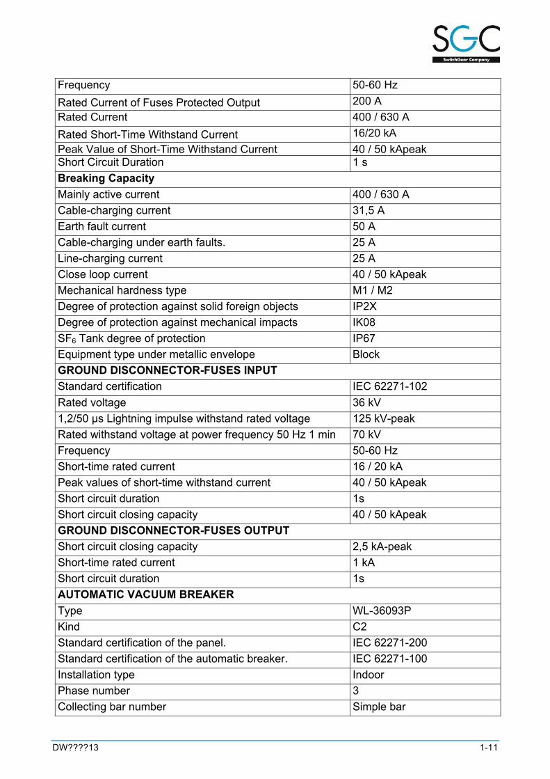
Frequency 50-60 Hz Rated Current of Fuses Protected Output 200 A Rated Current 400 / 630 A Rated Short-Time Withstand Current 16/20 kA Peak Value of Short-Time Withstand Current 40 / 50 kApeak Short Circuit Duration 1 s Breaking Capacity Mainly active current 400 / 630 A Cable-charging current 31,5 A Earth fault current 50 A Cable-charging under earth faults. 25 A Line-charging current 25 A Close loop current 40 / 50 kApeak Mechanical hardness type M1 / M2 Degree of protection against solid foreign objects IP2X Degree of protection against mechanical impacts IK08 SF6 Tank degree of protection IP67 Equipment type under metallic envelope Block GROUND DISCONNECTOR-FUSES INPUT Standard certification IEC 62271-102 Rated voltage 36 kV 1,2/50 μs Lightning impulse withstand rated voltage 125 kV-peak Rated withstand voltage at power frequency 50 Hz 1 min 70 kV Frequency 50-60 Hz Short-time rated current 16 / 20 kA Peak values of short-time withstand current 40 / 50 kApeak Short circuit duration 1s Short circuit closing capacity 40 / 50 kApeak GROUND DISCONNECTOR-FUSES OUTPUT Short circuit closing capacity 2,5 kA-peak Short-time rated current 1 kA Short circuit duration 1s AUTOMATIC VACUUM BREAKER Type WL-36093P Kind C2 Standard certification of the panel. IEC 62271-200 Standard certification of the automatic breaker. IEC 62271-100 Installation type Indoor Phase number 3 Collecting bar number Simple bar
1-12 DW????13
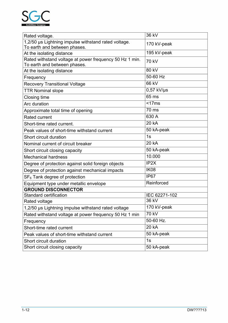
Rated voltage. 36 kV 1,2/50 μs Lightning impulse withstand rated voltage. To earth and between phases.
170 kV-peak
At the isolating distance 195 kV-peak Rated withstand voltage at power frequency 50 Hz 1 min. To earth and between phases.
70 kV
At the isolating distance 80 kV Frequency 50-60 Hz Recovery Transitional Voltage 66 kV TTR Nominal slope 0,57 kV/μs Closing time 65 ms Arc duration <17ms Approximate total time of opening 70 ms Rated current 630 A Short-time rated current. 20 kA Peak values of short-time withstand current 50 kA-peak Short circuit duration 1s Nominal current of circuit breaker 20 kA Short circuit closing capacity 50 kA-peak Mechanical hardness 10.000 Degree of protection against solid foreign objects IP2X Degree of protection against mechanical impacts IK08 SF6 Tank degree of protection IP67 Equipment type under metallic envelope Reinforced GROUND DISCONNECTOR Standard certification IEC 62271-102 Rated voltage 36 kV 1,2/50 μs Lightning impulse withstand rated voltage 170 kV-peak Rated withstand voltage at power frequency 50 Hz 1 min 70 kV Frequency 50-60 Hz. Short-time rated current 20 kA Peak values of short-time withstand current 50 kA-peak Short circuit duration 1s Short circuit closing capacity 50 kA-peak

DW????13 2-1
2 TRANSPORT AND OPERATION
The DI-2 panels are delivered totally plastic-wrapped and fixed in a pallet. Do not remove the packing is advised until it will be located in its final position.
Panels have to be in vertical position, on a pallet or on the floor. A forklift truck must be used for its operation. The panel will be always located in front of the driver in order to avoid potential damages in the front. Slings or rocker arms are also valid. These are fixed to the elevator pieces, which are located in upper area of the panels, in order to pull in a vertical direction with an angle of 55 ° for slings and of 80 ° for rocker arms.
In case of forklift truck transport, it should be considered that gravity center is quite high and therefore it is easy to turn over

DW????13 3-1
3 STORAGE
Conditions for storage are the following: Vertical position. Not to pile up. Rain protection. Direct solar radiation protection. Range of temperature for storage: -25 ºC y 55 ºC. After time of storage and before installation, DI-2 panels must be carefully cleaned in particular all the insulating parts.

DW????13 4-1
4 INSTALLATION
4.1 General tips To transport the panel from the storage to the installation place with its original packaging is recommended. The place of installation must have similar conditions than the storage place, in other words, the panel must be protected against rain and direct solar radiation. Temperature in the installation place must not be lower than – 10 °C and higher than 55 °C. The DI-2 panels are supplied with a plastic wrap protection. SGC nv - SwitchGear Company recommends a visual inspection in order to check if the panel has suffered damages in the transport. In case of verifying any type of damage, before installation, please contact with SGC nv - SwitchGear Company’s technical department. From the point of view of people security, the distance to the walls or lateral panels must be of a minimum of 50 mm and to the back walls of 100 mm. The thickness of the service corridors must be wide enough to allow an easy operation and inspection of the installations as well as free motion and transport of devices in the installation and maintenance operations. This thickness will not be lower than the following: Operation corridors with voltage elements in one side. 1000 mm. Operation corridors with voltage elements in both sides. 1200mm. Inspection corridors with voltage elements in one side. 800 mm. Inspection corridors with voltage elements in both sides. 1000mm. The aforementioned values must be totally open, in other words, measured between the projecting elements such as controls, rails, etc. NOTE. The distance between the panel ceiling and the installation place ceiling will be of a minimum of 300 mm in the traditional transformer substations. In the compact type with outside operation, this high can be of 40 mm.
4.2 Fixing The panel must be fixed directly on the floor or different sections, therefore 4 holes of 13 mm diameter are located in its inferior part. In order to access to these positions, is required to remove the inferior doors.

4-2 DW????13
4.3 Junction of panels Union between extensible DI-2 panels in order to connect them electrically and mechanically is made by SGC nv - SwitchGear Company double connectors. This system allows the panels connection without entering in the gas compartment. The system is composed of three connectors which are located in the bushings and sealed the joint, monitoring the electric field. In order to carry out the proper junction between the extensible panels of the DI-2 system or the proper installation of the insulated cover for internal cone bushings protection, the following tools must be available:
• 2 Key 12-13. • 1 13 mm Dynamometric key and 10 mm small opening. • 1 Acetone bottle. • 1 Clean and dry cloth.
1. Locate the first panel in the corresponding position in the transformer substation. 2. Clean the internal cone bushings in both panels and the coupling connector with a
clean and dry cloth. 3. Lubricate with the silicone grease that is supplied with the connector, the junction
surface of the bushings and connectors. 4. Insert nylon wires (in order to evacuate air between bushing and connector) at the
same time that the connectors.
5. Screw on the earth wire of the connectors with a hexagonal bolt M8x20 ISO 4017 and two washers M8 according with DIN 125.

DW????13 4-3
6. Fix the neoprene joint all around the panel.
7. Remove bolts of the earth general line.

4-4 DW????13
8. Move the second panel according with the figure below and remove the nylon wires.
9. Join the panels in B positions as showed in the figure below using hexagonal bolts M8x60 ISO 4017, two plain washers M8 according with DIN 125 and two nuts M8 ISO 4032.
10. Join the panels in A positions as showed in the figure below, using three hexagonal bolts M8x25 ISO 4017, three plain washers M8 DIN 125 and three nuts M8 ISO 4032.

DW????13 4-5
11. Join the panels in C position as showed in the figure below using an hexagonal bolt M8x25 ISO 4017 and a plain washer M8 ISO 4032.
12. Join the general earth lines of the panels.

4-6 DW????13
4.4 End of panels The extensible panels prepared for a future extensibility of the transformer substation must include insulated covers to protect the internal cone bushings. The proper installation of such insulated covers must be carried out according with the following instructions:
1. Clean carefully the bushing internal faces. 2. Lubricate with the silicone grease that is supplied in the kit, the insulate silicone
body and in the bushing internal faces. 3. Insert the insulate silicon body of the cover in the bushing with the clamp in order to
remove the air.
4. Remove the clamp when the cover is located at the bottom of the bushing. 5. Fix the sheet screwing three bolts.
4.5 Grounded equipment When the cell is fixed on its final location, it must be earthed by connection of the side plates to the general earth line of the transformer substation.

DW????13 4-7
Note.- It is an essential condition of security for the equipment to be earthed.
4.6 Connection of cables Service line of medium voltage, outputs to transformers and other panels are carried out by cables. Junction operations of the connectors to the cables will be carried out by qualified personnel who are duly trained and follow the instructions of the connector manufacturer in detail. In the DI-2 system of panels, cables for line function and automatic protection must use 630 A connectors. For protection functions, cables must be manufactured with plug-in connectors of 250 A.
4.6.1 Installation steps In order to connect the cables, follow the instructions taking into account that shield is not a protection against direct contacts. It is totally forbidden to handle the connectors with voltage although these were shielded. When there is a system with voltage and in the upper busbar a reserve panel with voltage and without cables in the inferior bushings is left; insulated covers for the bushings or connection of the ground disconnector blocking this position with a lock or padlock is required. Sequence of steps:
1. Connect the ground disconnector. 2. Remove the door of the cables. 3. Remove the bushing protection, clean with a dry cloth and lubricate all the contact
surface of the cable with silicone grease supplied with the connector. 4. Connect the terminals on the frontal bushings. 5. Fix the first clamp. 6. Lean the cable on the clamp, move and tighten the next clamp against the cable
and block it in this position.

4-8 DW????13
7. Repeat this action with the rest of the cables.
8. Connect the earth wires of the cables and the terminals to the general earth line of the panel.
9. Put the door in its position.
4.7 Fuses A fuse inserted in an electric circuit is devoted to protect this circuit and its associated elements permanently. The manner in which the fuse will work, not only depend of the manufactured precision but also of its proper manufacture. The fuse cartridge will be storaged in its original packaging up its use. Before its operation, it must be checked that all fuse cartridge do not have a fall or knock which could break some of its internal conductors.
4.7.1 Fuse selection To select an appropriate fuse of rated voltage 24 or 36 kV, the following considerations are taken into account: All the fuses implemented in the DI-2 panels must be manufactured in agreement with IEC 60282-1 and with the following dimensions:
kV L 24 442 36 537

DW????13 4-9
Fuse rated current is generally higher than normal current of service, therefore, rated current will be chosen in agreement with the rated power and voltage of the transformer according with the following table:
Fuses losses should not be greater than 50 W, when working at the current corresponding with maximal charge of the transformer. Without this information, when working in the air, should be at 50 % of its rated current. Inaccurate selection of the fuse rated current may deteriorate fuses, contacts or metallic housings of the panel.
4-10 DW????13
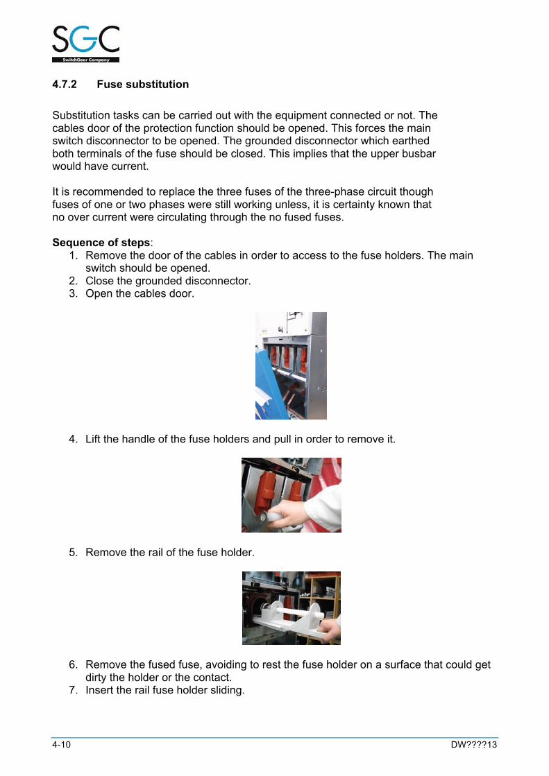
4.7.2 Fuse substitution Substitution tasks can be carried out with the equipment connected or not. The cables door of the protection function should be opened. This forces the main switch disconnector to be opened. The grounded disconnector which earthed both terminals of the fuse should be closed. This implies that the upper busbar would have current. It is recommended to replace the three fuses of the three-phase circuit though fuses of one or two phases were still working unless, it is certainty known that no over current were circulating through the no fused fuses. Sequence of steps:
1. Remove the door of the cables in order to access to the fuse holders. The main switch should be opened.
2. Close the grounded disconnector. 3. Open the cables door.
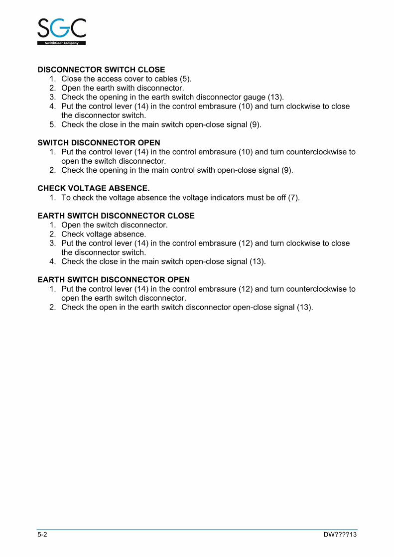
4. Lift the handle of the fuse holders and pull in order to remove it.
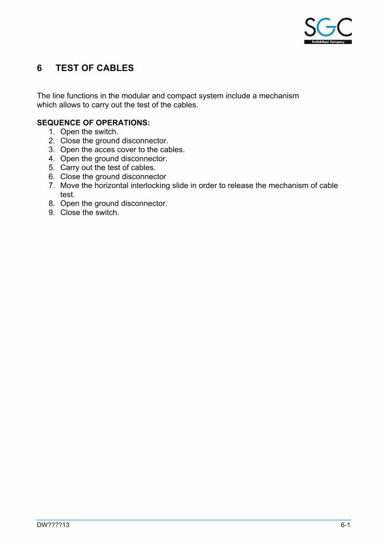
5. Remove the rail of the fuse holder.
6. Remove the fused fuse, avoiding to rest the fuse holder on a surface that could get dirty the holder or the contact.
7. Insert the rail fuse holder sliding.

DW????13 4-11
8. Reset the fuse holder striker up to block it in this position.
9. Place the fuse holder sliding up to the holder limit and put down the handle checking that it is blocked in this position.
10. Close the door of the cables. 11. Start the panel.
4.8 Phases consistency Once the medium voltage panels are fixed and connected in the transformer substation, its correct connection has to be verified, checking the consistency of the phases. It is possible to measure the consistency of the phases with a multimeter of input impedance higher than 20MΩ (20 KΩ/V scale of 1000V) Considering that the measurement range will be the following:
Between a phase and neutral of the same base ~110 Vac. Between different base phases < 50 Vac. Between different phases >130 Vac.

DW????13 5-1
5 OPERATING SECUENCY
Note: Before operating, it must be checked that manometer pressure is located in the green area, according with the panel pressure, showed in the sheet of characteristics. When the voltage indicators are switched off, it must be checked that are working correctly.
5.1 Line function
NOTE. - Be a blockage that impedes operating on the disconnector switch with the cables door (5) open and / or earth switch closed.
6 MANOMETER
8 SYNOPTIC 1 NAMEPLATE
7 VOLTAGE DETECTION SYSTEM
5 CABLES DOOR
9 MAIN SWITCH OPEN-CLOSE SIGNAL
12 MAIN EARTH DISCONNECTOR OPEN-CLOSE SIGNAL
10 MAIN SWITCH OPERATING AXIS
13 EARTH SWITCH DISCONNECTOR OPEN-CLOSE SIGNAL
14 CONTROL LEVER
5-2 DW????13
DISCONNECTOR SWITCH CLOSE
1. Close the access cover to cables (5). 2. Open the earth swith disconnector. 3. Check the opening in the earth switch disconnector gauge (13). 4. Put the control lever (14) in the control embrasure (10) and turn clockwise to close
the disconnector switch. 5. Check the close in the main switch open-close signal (9).
SWITCH DISCONNECTOR OPEN
1. Put the control lever (14) in the control embrasure (10) and turn counterclockwise to open the switch disconnector.
2. Check the opening in the main control swith open-close signal (9). CHECK VOLTAGE ABSENCE.
1. To check the voltage absence the voltage indicators must be off (7). EARTH SWITCH DISCONNECTOR CLOSE
1. Open the switch disconnector. 2. Check voltage absence. 3. Put the control lever (14) in the control embrasure (12) and turn clockwise to close
the disconnector switch. 4. Check the close in the main switch open-close signal (13).
EARTH SWITCH DISCONNECTOR OPEN
1. Put the control lever (14) in the control embrasure (12) and turn counterclockwise to open the earth switch disconnector.
2. Check the open in the earth switch disconnector open-close signal (13).

DW????13 5-3
5.2 Protection function
NOTE.-Be a blockage that impede operating on the disconnector switch with the cables and fuses door (8) open and / or earth switch closed.
1 MANOMETER
2 SYNOPTIC 3 NAMEPLATES
9 VOLTAGE DETECTION SYSTEM
8 FUSE AND CABLES DOOR
10 MAIN SWITCH OPEN-CLOSE SIGNAL
13 MAIN EARTH DISCONNECTOR OPERATING AXIS
11 MAIN SWITCH OPERATING AXIS
14 EARTH SWITCH DISCONNECTOR OPEN-CLOSE SIGNAL
6 MELTED FUSE SIGNAL
7 PUSH BOTTOM FOR QUICK OPENING OF THE PROTECTION SWITCH
16 CONTROL LEVER

5-4 DW????13
DISCONNECTOR SWITCH CLOSE 1. Close the access cover to cables and fuses (8. 2. Open the earth swith disconnector. 3. Check the opening in the earth switch disconnector gauge (14). 4. Put the control lever (16) in the control embrasure (11) and turn counterclockwise to
resetting the equipment. 5. Put the control lever (16) in the control embrasure (11) and turn clockwise to close
the disconnector switch. 6. Check the close in the main switch open-close signal (10).
SWITCH DISCONNECTOR OPEN
1. Put the control lever (16) in the control embrasure (11) and turn counterclockwise to open the switch disconnector or operating the push bottom for the quick opening of the protection switch (7).
2. Check the opening in the main control swith open-close signal (10). CHECK VOLTAGE ABSENCE.
1. To check the voltage absence the voltage indicators must be off (9).
EARTH SWITCH DISCONNECTOR CLOSE 1. Open the switch disconnector. 2. Check voltage absence. 3. Put the control lever (16) in the control embasure (13) and turn clockwise to close
the disconnector switch. 4. Check the close in the main switch open-close signal.
EARTH SWITCH DISCONNECTOR OPEN
1. Release the control embrasure of earth switch disconnector (13) with the vertical blockage (12) and closing the cables door (8).
2. Put the control lever (16) in the control embrasure (13) and turn counterclockwise to open the earth switch disconnector.
3. Check the open in the earth switch disconnector open-close signal (14). FUSES ACCESS
1. Open the switch disconnector. 2. Check the voltage absence. 3. Close the earth swith disconnector. 4. Open the fuse and cables door (8) moving the horizontal blockade device (15).

DW????13 5-5
5.3 Circuit breaker function with protection relay
Nota.- Be a blockage thats impedes operating on the earth switch disconnector with the disconnector switch or associate switch disconnector closed or cables door open.
1 MANOMETER
10 SYNOPTIC 3 ASSOCIATE SWITCH DISCONNECTOR MAIN AXIS
2 VOLTAGE DETECTION SYSTEM
4 OPEN BOTTOM
5 MECHANICAL COUNTING
6 CLOSED BOTTOM
8 SPRING INDICATING
12 SPRING CHARGE AXIS
14 MAIN EARTH DISCONNECTOR OPERATING AXIS
15 EARTH SWITCH DISCONNECTOR OPEN-CLOSE SIGNAL
17 MAIN SWITCH OPEN-CLOSE SIGNAL
11 ASSOCIATE SWITCH SIGNAL
13 NAMEPLATE
18 CABLES DOOR
19 HANDLE FOR MANUAL CHARGE OF SPRING FOR CIRCUIT BREAKER

5-6 DW????13
DISCONNECTOR SWITCH CLOSE. 1. Close the access cover to cables and release the control embrasure of earth switch
disconnector. 2. Open the earth switch disconnector. 3. Check the opening in the earth switch disconnector signal. 4. Release the control embrasure of associate switch disconnector witch the vertical
blockage. 5. Put the control lever in the control in the control embrasure and turn clockwise to
reseting the equipment. 6. Check the close in the associate switch disconnector signal. 7. If It’s necessary charge the completly the springs putting the spring lever in it control
embrasure and turn counterclockwise completly. 8. To close the automatic breaker push the closed bottom. 9. Check the close in the asóciate switch signal.
SWITCH DISCONNECTOR OPEN.
1. Pus the open bottom to open the switch disconnector. 2. Check the opening in the switch disconnector signal. 3. Release the control switch embrasure of associate switch signal. 4. Put the control lever in the control in the control embrasure and turn
counterclockwise to open the switch disconnector. 5. Check the opening in the associate switch signal.
CHECK VOLTAGE ABSENCE.
1. To check the voltage absence the voltage indicators must be off. EARTH SWITCH DISCONNECTOR CLOSE
1. Open the switch disconnector and the associate switch disconnector. 2. Check voltage absence. 3. Release the control embrasure of earth switch disconnector with the vertical
blockage. 4. Put the control lever in the control embrasure and turn clockwise to close the
disconnector switch. 5. Check the close in the main switch open-close signal.
EARTH SWITCH DISCONNECTOR OPEN
1. Release the control embrasure of earth switch disconnector with the vertical blockage and closing the cables door.
2. Put the control lever in the control embrasure and turn counterclockwise to open the earth switch disconnector.
3. Check the open in the earth switch disconnector open-close signal.
DW????13 6-1
6 TEST OF CABLES
The line functions in the modular and compact system include a mechanism which allows to carry out the test of the cables. SEQUENCE OF OPERATIONS:
1. Open the switch. 2. Close the ground disconnector. 3. Open the acces cover to the cables. 4. Open the ground disconnector. 5. Carry out the test of cables. 6. Close the ground disconnector 7. Move the horizontal interlocking slide in order to release the mechanism of cable
test. 8. Open the ground disconnector. 9. Close the switch.

DW????13 7-1
7 LOCATION OF THE CURRENT COLLECTOR
In the remote control panels, the current collector for phases is located in the cables door of each line function, as well as the divided core current collector for homopolar

DW????13 8-1
8 SECURITY
High voltage switchgear is only considered safe when it has been installed in agreement with the required installation rules and used and maintained according with the instructions of this guide.
8.1 Security elements The installation place must fulfill with the security requirements in agreement with the legislation currently in force, having the following security elements:
- Isolating foot stool. - Medium voltage insulated gloves. - Safety helmet. - Protective shield. - Fire extinguisher of 89B minimun efficiency. - Warning signs of danger. - Emergency phone numbers. - Poster with the five golden rules for working without voltage:
o Insulate the whole assembly from the active parts. o Ensure the assembly against possible accidental connections.
- Check that the assembly is with no-voltage. - All possible voltage sources affecting the work area must be in earth and short-
circuit position. - Delimit working areas by placing the right safety signs.
8.2 User security cautions The user should:
- Restrict the access to the installation for trained and authorized people. - Train regularly operators and rest of the personnel in relation with risks and security
requirements, including the local rules. - Keep the equipment in right conditions and updated in relation with technical rules,
especially interlocking and protection devices. - Select equipment which minimizes risks derivate of personnel inaccurate operation
(for instance, grounded disconnector in lines, motorized operating axis for allowing remote control).
- Coordinate the protection system with properties of the product (for instance, do not carry out resets with internal faults).
- Make earthed procedures considering the reference difficulty and the understanding of complex regulations and the switchgear operation.
- Equip clearly the equipment for an easy identification of the individual devices and gas compartments.
- Especially for maintenance, reparation or extension: o Assure that the maintenance works, reparation and extension will be carried
out only for trained personnel.

8-2 DW????13
o Provide a security and protection plan. Indicate the responsible of planning, implement and fulfill the security and protection rules.
o Before starting, check the interlocks and the protection devices. o Pay special attention to the manual operations, especially when the
switchgear has voltage. o Inform before operating to the personnel who may stay close to the
switchgear (for instance with a siren or light signal). o Signpost emergency exits and keep areas free of obstacles. o Train the personnel in how to work in safe way in the switchgear and what to
do in an emergency situation.

DW????13 9-1
9 MAINTENANCE
Maintenance of this type of installations must be carried out by qualified personnel according with the law in force in order to install and operate voltage equipments. The DI-2 panel systems have a lifespan higher than 30 years, as long as the installation will be made according with this manual. In addition accurate fuses and cables must be used and connectors must be perfectly made and installed. The electrical and mechanical tests carried out in high quality national and international laboratories guarantee the accurate operation of the disconnector elements. It is recommended to carry out the following actions. Once a year and without disconnecting the panel, it will be checked: SF6 gas pressure. Manometer pointer located in the green area. If the pointer is located in the red area, please contact with SGC nv – SwitchGear Company’s technical-commercial department and do not operate the panel. If the pointer is close to the red area, the service will be normal but a new inspection must be made in a maximum of three months. However, it should be reported to SGC nv – SwitchGear Company’s technical-commercial department who will give the appropriate instructions. Operation of voltage indicators. To check the operation of voltage indicators, panel signals must be disconnected of its base and to supply with testing terminals with a minimum voltage of 30 Vca between phase and neutral and each one of the phases. It should be checked that each one of the three signals are flashing. It can be connected either of phase and neutral because there is no polarity. In case of one or more light signs do not shine; this unit must be replaced for an original one. The voltage indicator can be replaced if needed. In this case, screws which are fixing the upper door and others located at left and right side of the indicator must be removed. Subsequently, switch the indicator back connector off without disconnecting the line voltage.
DW????13 10-1
10 SPARE PARTS
SGC nv - SwitchGear Company original spare parts are required if some replacement is needed. Fuses replacement must be made with SGC nv - SwitchGear Company fuses, following the instructions given in this manual. Any kind of replacement or change must be made by SGC nv - SwitchGear Company authorized personnel. SGC nv - SwitchGear Company suggests having, in the installation place of the DI-2 panels, the following spare parts: three fuses and an operating axis.

DW????13 11-1
11 ENVIRONMENTAL INFORMATION
The DI-2 panel systems are metal enclosed manufactured with SF6. Sulphur hexafluoride (SF6) is a gas with excellent dielectric properties which allow rapid electric arc extinction and therefore it has been widely used in medium voltage switch and panels SF6 is a greenhouse gas effect whose Atmospheric Warming Potential (AWP) is of 22.200 units. Therefore, its releasing must be controlled and reduced according with the laws in force in each country and requirements of the Kyoto Protocol. Until now, there is no gas which can replace the SF6 despite of research efforts carried out. In consequence, there is a global responsibility of rational and responsible use of this product. Therefore, SF6 must be recovery for recycling and treatment at the end of product useful life, avoiding its releasing to the atmosphere. This extraction must be carried out by qualified personnel.

11-2 DW????13
Notes:

THE SPECIALIST IN MEDIUM VOLTAGE SWITCHGEAR
DW????13 ©2013 SGC nv - SwitchGear Company


![SAN]OSE CITYOF MemorandumFeeder from Switchgear M5 to Switchgear S16B 6. Feeder from Switchgear M5 to Switchgear ESB Engineer'sEstimate $384,787 $77,720 $211,326 $747,139 ... Ifthisproject](https://static.fdocuments.us/doc/165x107/5e7fcbe33356ee7623111eaf/sanose-cityof-feeder-from-switchgear-m5-to-switchgear-s16b-6-feeder-from-switchgear.jpg)